OMAP4430 Multimedia Device - TI. · PDF filecharge of the OMAP4 ABE HAL and the multimedia...
52
SWPU245B–October 2010–Revised January 2011 1 www.ti.com OMAP4430 Silicon Revision ES2.x Audio Back-End (ABE) and Hardware Abstraction Layer (HAL) Addendum © 2010-2011, Texas Instruments Incorporated Public Version OMAP TM Public version OMAP4430 Multimedia Device Silicon Revision ES2.x Texas Instruments OMAP™ Family of Products Audio Back-End (ABE) and Hardware Abstraction Layer (HAL) Addendum Version B Technical Reference Manual Literature Number: SWPU245B October 2010–Revised January 2011
Transcript of OMAP4430 Multimedia Device - TI. · PDF filecharge of the OMAP4 ABE HAL and the multimedia...

SWPU245B–October 2010–Revised January 2011
1
www.ti.com OMAP4430 Silicon Revision ES2.x
Audio Back-End (ABE) and Hardware Abstraction Layer (HAL) Addendum
© 2010-2011, Texas Instruments Incorporated
Public Version
OMAPTM
Public version
OMAP4430 Multimedia Device
Silicon Revision ES2.x Texas Instruments OMAP™ Family of Products Audio Back-End (ABE) and Hardware Abstraction Layer (HAL) Addendum Version B
Technical Reference Manual
Literature Number: SWPU245B
October 2010–Revised January 2011

2
Public Version
OMAP4430 Silicon Revision ES2.x Audio Back-End (ABE) and Hardware Abstraction Layer (HAL) Addendum
SWPU245B–October 2010–Revised January 2011
www.ti.com
© 2010-2011, Texas Instruments Incorporated
WARNING: EXPORT NOTICE
Recipient agrees to not knowingly export or re-export, directly or indirectly, any product or technical data (as defined by the U.S., EU and other Export Administration Regulations) including software, or any controlled product restricted by other applicable national regulations, received from Disclosing party under this Agreement, or any direct product of such technology, to any destination to which such export or re-export is restricted or prohibited by U.S. or other applicable laws, without obtaining prior authorization from U.S. Department of Commerce and other competent Government authorities to the extent required by those laws. This provision shall survive termination or expiration of this Agreement. According to our best knowledge of the state and end-use of this product or technology, and in compliance with the export control regulations of dual-use goods in force in the origin and exporting countries, this technology is classified as follows: −US ECCN: 3E991 −EU ECCN: EAR99 And may require export or re-export license for shipping it in compliance with the applicable regulations of certain countries.

SWPU245B–October 2010–Revised January 2011
3
www.ti.com OMAP4430 Silicon Revision ES2.x
Audio Back-End (ABE) and Hardware Abstraction Layer (HAL) Addendum
© 2010-2011, Texas Instruments Incorporated
Public Version
Table of Contents List of Figures .................................................................................................................................... 5 List of Tables ..................................................................................................................................... 6 List of ABREVIATIONs ...................................................................................................................... 6
Revision History................................................................................................................................... 7 1 Introduction .................................................................................................................................. 8
1.1 Feature List............................................................................................................................. 9 1.2 Audio mixing in OMAP4.......................................................................................................... 10 1.3 Audio mixing of multichannel audio........................................................................................ 10
2 Top level view of the ABE-HAL services ................................................................................... 12 2.1.1 AESS processing.............................................................................................................. 14 2.1.2 AE Port - Protocols ........................................................................................................... 15
3 List of services ............................................................................................................................. 20 3.1 Data Types used for APIs ...................................................................................................... 20 3.2 Hardware control API list ........................................................................................................ 20
3.2.1 abe_reset_hal................................................................................................................... 20 3.2.2 abe_load_fw ..................................................................................................................... 20 3.2.3 abe_reload_fw ..................................................................................................................21 3.2.4 abe_write_event_generator.............................................................................................. 21 3.2.5 abe_read_use_case_opp................................................................................................. 21 3.2.6 abe_set_opp_processing ................................................................................................. 21 3.2.7 abe_connect_serial_port .................................................................................................. 22 3.2.8 abe_init_ping_pong_buffer............................................................................................... 22 3.2.9 abe_connect_dmareq_ping_pong_port............................................................................ 22 3.2.10 abe_connect_irq_ping_pong_port.................................................................................... 22 3.2.11 abe_connect_cbpr_dmareq_port ..................................................................................... 23 3.2.12 abe_enable_data_transfer ............................................................................................... 23 3.2.13 abe_disable_data_transfer............................................................................................... 23 3.2.14 abe_reset_port ................................................................................................................. 23 3.2.15 abe_set_ping_pong_buffer............................................................................................... 24 3.2.16 abe_read_next_ping_pong_buffer ................................................................................... 24 3.2.17 abe_read_remaining_data ............................................................................................... 24 3.2.18 abe_read_offset_from_ping_buffer .................................................................................. 24 3.2.19 abe_read_port_address ................................................................................................... 25
3.3 Signal processing API list ....................................................................................................... 25 3.3.1 abe_write_gain, abe_write_mixer..................................................................................... 25 3.3.2 abe_set_router_configuration........................................................................................... 26 3.3.3 abe_write_equalizer ......................................................................................................... 26 3.3.4 abe_write_asrc .................................................................................................................26 3.3.5 abe_use_compensated_gain ........................................................................................... 27 3.3.6 abe_mute_gain................................................................................................................. 27 3.3.7 abe_unmute_gain............................................................................................................. 27 3.3.8 abe_read_gain..................................................................................................................27
3.4 Interface and accessory control API....................................................................................... 27 3.4.1 abe_irq_processing .......................................................................................................... 28 3.4.2 abe_clear_irq.................................................................................................................... 28 3.4.3 abe_connect_debug_trace............................................................................................... 28
3.5 Data paths graphical view ......................................................................................................29 3.5.1 Data paths and features of the HAL releases 08 ............................................................. 29 3.5.2 Data paths and features of the HAL releases 09 ............................................................. 30
3.6 AESS registers descriptions................................................................................................... 31 3.7 Ports characteristics ............................................................................................................... 32 3.8 ABE Gains and MCPDM saturation ....................................................................................... 34 3.9 Clocks and peripheral synchronization................................................................................... 34

4
Public Version
OMAP4430 Silicon Revision ES2.x Audio Back-End (ABE) and Hardware Abstraction Layer (HAL) Addendum
SWPU245B–October 2010–Revised January 2011
www.ti.com
© 2010-2011, Texas Instruments Incorporated
4 Programming examples............................................................................................................... 35 4.1 AESS reset ............................................................................................................................. 35 4.2 Multimedia player in low-power mode.................................................................................... 35 4.3 System tones player ............................................................................................................... 36 4.4 Voice calls .............................................................................................................................. 37 4.5 Switching DMIC sources while rotating the screen ................................................................ 37 4.6 Equalizer................................................................................................................................. 38 4.7 Equalizer for microphones and decimation to 48kHz............................................................. 40 4.8 Equalizer for side-tone............................................................................................................ 40 4.9 FM radio recording on-the-fly ................................................................................................. 40 4.10 AE processing - Drift management ...................................................................................... 41 4.11 Serial ports FIFO thresholds .................................................................................................. 41 4.12 Audio Clicks............................................................................................................................ 41 4.13 Use-Case transitions .............................................................................................................. 43
4.13.1 Opening and closing ports – start/stop code sequence ................................................... 43 4.13.2 OPP transitions................................................................................................................. 43 4.13.3 TWL6040 transitions......................................................................................................... 44
5 Debugging ABE............................................................................................................................ 50 5.1 FIFO locations ........................................................................................................................ 50 5.2 Debug trace ............................................................................................................................ 51

SWPU245B–October 2010–Revised January 2011
5
www.ti.com OMAP4430 Silicon Revision ES2.x
Audio Back-End (ABE) and Hardware Abstraction Layer (HAL) Addendum
© 2010-2011, Texas Instruments Incorporated
Public Version
LIST OF FIGURES Figure 1 – Real-time mixing and filtering in ABE.............................................................................. 8 Figure 2 – OMAP multimedia mixers.................................................................................................. 10 Figure 3 – Multichannel mixing and routing (HDMI)......................................................................... 11 Figure 4 – ABE logical/physical port mapping.................................................................................. 13 Figure 5 – ABE-MMAV10GS70 Block Diagram.................................................................................. 14 Figure 6 – Data exchanged between peripherals and DMEM through ATC ports......................... 15 Figure 7 – Extracts from the Attila functional specification for sDMA request lines ................... 16 Figure 8 – Data exchanged between a DMA and DMEM through ATC ports ................................. 17 Figure 9 – Data exchanged between a DMA and DMEM using the ping-pong protocol............... 18 Figure 10 – Ping-Pong protocol.......................................................................................................... 19 Figure 11 – Processing flow with OPP values of the release 08..................................................... 29 Figure 12 – Processing flow with OPP values of the release 09..................................................... 30 Figure 13 – ABE HAL gain settings, versus the low-power configuration of TWL6040 ............... 34 Figure 14 – ABE HAL for ABE-AESS reset ........................................................................................ 35 Figure 15 – ABE HAL for enabling low-power audio player ............................................................ 36 Figure 16 – ABE HAL for low-latency tones generation .................................................................. 37 Figure 17 – ABE HAL for Voice call settings..................................................................................... 37 Figure 18 – ABE HAL codes for uplink router configuration........................................................... 38 Figure 19 – Matlab source code for equalizer coefficients' computation ...................................... 39 Figure 20 – ABE HAL for loading equalizer's coefficients............................................................... 39 Figure 21 – White noise filtered (log scale, linear scale) ................................................................. 39 Figure 22 – Matlab source code for microphone equalizer computation ...................................... 40 Figure 23 – ABE HAL for loading microphone equalizer's coefficients ......................................... 40 Figure 24 – OPP transitions ................................................................................................................ 44 Figure 25 – Headset / Earphone transitions...................................................................................... 45 Figure 26 – Hands-free transitions..................................................................................................... 46 Figure 27 – PDM states transitions .................................................................................................... 47 Figure 28 – TWL6040 clocks tree and transitions ............................................................................ 47 Figure 29 – Microphones transitions ................................................................................................. 48 Figure 30 – TWL6040 Power-Down conditions ................................................................................. 49

6
Public Version
OMAP4430 Silicon Revision ES2.x Audio Back-End (ABE) and Hardware Abstraction Layer (HAL) Addendum
SWPU245B–October 2010–Revised January 2011
www.ti.com
© 2010-2011, Texas Instruments Incorporated
LIST OF TABLES Table 1 : ABE-HAL Feature list ........................................................................................................... 9 Table 2 : ABE Physical ports list ........................................................................................................ 12 Table 3 : Logical ports and default protocols ................................................................................... 13 Table 4 : ATC Descriptor configuration (From [1]) ........................................................................... 16 Table 5 : List of the data types ........................................................................................................... 20 Table 6 : Mixers' port indexes ............................................................................................................. 26 Table 7 : AESS registers...................................................................................................................... 31 Table 8 : Port and protocol.................................................................................................................. 32 Table 9 : Use-cases and OPP .............................................................................................................. 33 Table 10 : Clocks configurations with DMIC ..................................................................................... 34 Table 11 : McBSP thresholds .............................................................................................................. 41 Table 12 : Maximum gains to set in downlink paths DL1 / DL2....................................................... 49 Table 13 : ATC DMA requests ............................................................................................................. 50 Table 14 : ATC FIFO DMEM offset ...................................................................................................... 51
LIST OF ABREVIATIONS AE : Audio Engine, part of the AESS. Makes the signal processing operations AESS : Audio Engine Sub-System, part of ABE. Includes AE, ATC, timers and clock control ATC : Audio Traffic Controller. Makes the data move between the DMEM and peripherals DMEM : Data memory, part of the AE. Used to control the processing and do data moves with ATC. SMEM, PMEM, CMEM : AE tightly coupled memories (samples, program, coefficients) HAL : Hardware Abstraction software Layer OPP: clock percentage operating point (100%, 50%, 25%) FW : Audio Engine Firmware Physical Ports : ports managed by the ATC (DMA, DMIC, McPDM, McBSP, etc…) AE Ports : I/O connections of the FW to the physical ports. Link : data connection between a Physical port and an AE Port. AE Feature : signal processing operation inserted in the audio stream ASRC, EQ: asynchronous sample-rate converter, equalizer MMI : Man Machine Interface MP3 use-case: Audio player can be not only MP3 but any MPEG player, OGG, WMA, etc… Sink, Source: from the host processor point of view some AE port are sink or source of samples

SWPU245B–October 2010–Revised January 2011
7
www.ti.com OMAP4430 Silicon Revision ES2.x
Audio Back-End (ABE) and Hardware Abstraction Layer (HAL) Addendum
© 2010-2011, Texas Instruments Incorporated
Public Version
Revision History Version Literature
Number Date Notes
0.94
N/A
June 2010
Added a chapter for AMIC/DMIC equalizer computation Added a separate capability of tuning AMIC and DMIC with abe_write_equ() Added abe_use_compensated_gain(), abe_(un)mute_gain(), Removed abe_set_dmic_filter(), abe_select_main_port() Changed the IIR25 coefficients description Updated the write_equalizer API, and add a recommendation to lower the gain. Updated the description of time synchronizations.
0.95
N/A
October 2010
Corrected description of the APIs : abe_init_ping-pong_buffer, abe_connect_dmareq_ping_pong_port, abe_connect_irq_ping_pong_port, abe_set_ping_pong_buffer, abe_read_next_ping_pong_buffer, abe_read_remaining_data. Corrected Ping-Pong FW function pseudo description. Corrected Programming example for Ping Pong with MCU IRQ.
A
SWPU245
December 2010
Added description of new API abe_read_offset_from_ping_buffer. Added 44.1KHz support at MM_EXT_OUT port at OPP25. Added description of abe_read_gain API. Updated description of APIs abe_write_gain, abe_mute_gain, abe_unmute_gain. Added data paths graphical view related to HAL 09 releases. Added a chapter on AESS registers. Port naming clarification.
B SWPU245 January 2011
Added new APIs abe_reload_fw, added a chapter on start/stop programming sequences and audio clicks, removed abe_read_hardware_description. Removed vx_dl_split data type.

8
Public Version
OMAP4430 Silicon Revision ES2.x Audio Back-End (ABE) and Hardware Abstraction Layer (HAL) Addendum
SWPU245B–October 2010–Revised January 2011
www.ti.com
© 2010-2011, Texas Instruments Incorporated
1 Introduction The purpose of this document is to detail the implementation of audio use-cases using the Audio Engine (AE) of the Audio Back-End (ABE) and its Hardware Abstraction Layer (HAL). The figure below depicts an example of the main audio processing blocks. The ARM host processor is in charge of the OMAP4 ABE HAL and the multimedia players. An external Modem device is in charge of the cellular voice processing. The Audio Engine of the ABE holds the real-time mixer feature.
Figure 1 – Real-time mixing and filtering in ABE
The ABE is in charge of the hard-real time mixing and basic filtering of the audio streams originated from the host processors or from hardware peripherals (MIDI players, FM radio, external Modem devices, A/D converters). For example generating tones on top of FM radio or managing the sound equalization is possible without going through the host processors. The functional partitioning between HAL and Audio upper layers is: - The HAL is in charge of the abstraction of the Audio Engine (AE) memory mapping, the AESS (Audio
Engine Sub-System) control registers.
The routing of the samples to TWL6040 is managed in the AE. There is no routing capability in TWL6040: the PDM-DL interface slots 0/1 are dedicated to earphone and headset drivers, slots 2/3 are dedicated to hands free driver, slot 5 and the control line are dedicated to Vibra/Haptics. When the Audio Engine generates an interrupt to the host, the HAL will manage the interpretation.
- Audio upper layers make the interface of the ABE hardware device drivers (McBSP, McASP, SLIMbus, McPDM, DMIC) to other device drivers (I2C, UART) and to the operating system.

SWPU245B–October 2010–Revised January 2011
9
www.ti.com OMAP4430 Silicon Revision ES2.x
Audio Back-End (ABE) and Hardware Abstraction Layer (HAL) Addendum
© 2010-2011, Texas Instruments Incorporated
Public Version
1.1 Feature List
This paragraph lists the ABE-HAL features. Features Comments Ports ABE-HAL allows connections to sDMA to hardware FIFOs of :
MM_UL_PORT for up to 8 data paths (4 stereo channels) MM_UL2_PORT dedicated to audio recording VX_UL_PORT holding the voice uplink path TONES_DL_PORT used for the low-latency notification tones VX_DL_PORT holding the voice-downlink path MM_DL_PORT dedicated to multimedia and low-power audio use-cases with an
optional ping-pong buffer. VIB_DL_PORT used for vibrator and haptics interface The ports are exchanging 8 to 32bits data MSB aligned on a 32bits container. MM_DL allows receiving two concatenated 16bits Left/Right samples per 32bits accesses. The sampling rate is 48kHz. Voice paths use 8 or 16kHz. MM_DL use 44.1kHz or 48kHz. The sampling rate of MM_DL and voice ports can be adjusted with 1ppm accuracy using the asynchronous sample-rate converters.
Gain control The mixer's gain balancing is tuned with 0.1dB precision with smoothed transitions Routing Allows routing capabilities of microphones and the "echo reference" path OPP The allowed OPP and clock values are tunable Equalizer The two downlink audio paths are equalized and can be tuned dynamically.
DMIC compensation of spectrum distortion
Table 1 : ABE-HAL Feature list

10
Public Version
OMAP4430 Silicon Revision ES2.x Audio Back-End (ABE) and Hardware Abstraction Layer (HAL) Addendum
SWPU245B–October 2010–Revised January 2011
www.ti.com
© 2010-2011, Texas Instruments Incorporated
1.2 Audio mixing in OMAP4
ABE implements the real-time mixer and routers of the OMAP multimedia software architecture. The picture below describes the typical connections found when ABE is used with the multimedia framework of the OS.
Figure 2 – OMAP multimedia mixers
1.3 Audio mixing of multichannel audio
ABE is optimized for stereo audio streams. When multichannel needs to be played on the headset, the Host CPU is in charge of the virtual surround 5.1 to stereo translation. The resulted stereo stream can be processed and routed in ABE:

SWPU245B–October 2010–Revised January 2011
11
www.ti.com OMAP4430 Silicon Revision ES2.x
Audio Back-End (ABE) and Hardware Abstraction Layer (HAL) Addendum
© 2010-2011, Texas Instruments Incorporated
Public Version
Figure 3 – Multichannel mixing and routing (HDMI)

12
Public Version
OMAP4430 Silicon Revision ES2.x Audio Back-End (ABE) and Hardware Abstraction Layer (HAL) Addendum
SWPU245B–October 2010–Revised January 2011
www.ti.com
© 2010-2011, Texas Instruments Incorporated
2 Top level view of the ABE-HAL services This section gives the user's view of the HAL services, starting with an introduction to the data exchanged with the upper layers.
Physical port Samping
rate (kHz) Description
DMIC 96 Digital microphones Always used in the configuration of six samples sent to AESS. When DMIC is used in ultra-sonic mode the samples are not going
through AESS, but directly go through the sDMA. The DMIC ABE IP can be configured with several clock speeds on
the OMAP I/O pads, the high clock speed results in higher quality and higher power consumption. The DMIC IP distorts the spectrum shape differently depending on this clock speed. The HAL reconfigures the AESS correction filters depending on the selected clock speed.
MCPDMUL 96 Analog microphones from TWL6040 sampled at 96kHz. Always used in the configuration of two samples sent to AESS. When MCPDMUL are used in ultra-sonic mode the samples are
not going through AESS, but directly go through the sDMA MCPDMDL 88.2/96 Downlink TWL6040 paths sampled at 96kHz.
Always used in the configuration of six samples sent from AESS. MCBSP1 TX/RX 8/16/48 Used for Bluetooth voice and music MCBSP2 RX/TX 8/16/48 Used for the external cellular Modem and FM radio MCBSP3 RX/TX 8/16/44.1/48 Replacement of the MCPDMUL and MCPDMDL interfaces in case
of connections to audio ICs like AIC3254 SLIMBUS 8x(RX/TX) 8/16/44.1/48 Usage is under definition. MCASP NA Only used for the SPDIF use-case. Cannot be used with AESS. CBPr0 .. CBPr6 4 Circular buffer with release capability of the sDMA request.
Each CBPr is respectively connected to an sDMA request line 0 .. 6. DMA requests are sent on 4kHz rate. The sDMA will be programmed to exchange from 4 bytes to 384 bytes on each ABE sDMA request.
CBPr7 4/96 Unused. sDMA line #7 is reserved for AESS purpose and debug. The host application should reserve a memory place for receiving
128 bytes of traced AESS internal data on a 4kHz rate. This data will be used for post-mortem analysis.
Table 2 : ABE Physical ports list Concerning the naming rule, "RX" means reception from ABE point of view: for example MM_DL is receiving data from sDMA and McBSP1_RX corresponds to the RX pins of the serial interface. "DL" means "downlink" as inherited from Modem point of view ("forward" direction down from the antenna to the mobile direction): for example BT_DL port is intended to send voice from the network to the Bluetooth earpiece.
Logical port FS (kHz) Description MM_UL (TX) 48 Multichannel (x8) audio record
Default configuration : DMA connected to CBPr3, stereo MSB aligned
MM_UL2 (TX) 48 Stereo audio record Default configuration : DMA connected to CBPr4, stereo MSB aligned samples
VX_UL (TX) 8/16 Modem voice path uplink Default configuration :

SWPU245B–October 2010–Revised January 2011
13
www.ti.com OMAP4430 Silicon Revision ES2.x
Audio Back-End (ABE) and Hardware Abstraction Layer (HAL) Addendum
© 2010-2011, Texas Instruments Incorporated
Public Version
DMA connected to CBPr2, stereo MSB aligned samples PDM (TX) 88.2/96 Dedicated MCPDMDL IP (overlays the McBSP3_TX) MM_EXT_OUT (TX) 44.1/48 Multimedia output port BT_VX_DL (TX) 8/16 Voice output port (Bluetooth) MM_EXT_IN (TX) 48 Multimedia input port TDM (TX) 48 Dedicated to McBSP3_TX as replacement of McPDM_DL TDM (RX) 48 Dedicated to McBSP3_RX as replacement of McPDM_UL PDM (RX) 96 Dedicated MCPDMUL IP (overlays the McBSP3_RX) DMIC (RX) 96 Dedicated DMIC IP MM_DL (RX) 44.1/48 Multimedia stereo player port. Can be used either with sDMA
through CBPr or using a large Ping-Pong buffer. Default configuration : DMA connected to CBPr0, stereo MSB aligned samples
VX_DL (RX) 8/16 Modem voice path downlink Default configuration : DMA connected to CBPr1, stereo MSB aligned samples
TONES_DL (RX) 44.1/48 Low latency notification tones and key beeps Default configuration : DMA connected to CBPr5, stereo MSB aligned samples
VIB_DL (RX) 24 Vibrator and Haptic feedback, stereo port. Default configuration : DMA connected to CBPr6, stereo MSB aligned samples
MM_EXT_IN (RX) 48 Multimedia input port BT_VX_UL (RX) 8/16 Voice input port (Bluetooth)
Table 3 : Logical ports and default protocols
Figure 4 – ABE logical/physical port mapping

14
Public Version
OMAP4430 Silicon Revision ES2.x Audio Back-End (ABE) and Hardware Abstraction Layer (HAL) Addendum
SWPU245B–October 2010–Revised January 2011
www.ti.com
© 2010-2011, Texas Instruments Incorporated
2.1.1 AESS processing In audio player low-power mode, the audio engine can operate at 48 kHz or 44.1 KHz. When configured for 44.1 kHz the Audio Engine processes all inputs at 44.1 kHz. No resampling is performed. The sampling frequency on the Audio Engine ports is 44.1 kHz, and data format can be 16/24/32 bits per word mono or stereo. In all other cases, the Audio Engine processing consists in resampling the input samples to 48 kHz stereo format, doing the mixing and filtering operation, and saving the samples to a sink port with a new sampling and data formats. The sampling frequencies on the Audio Engine ports are 8/16/48 kHz, and the data format can be 16/24/32 bits per words mono or stereo, except in audio player low-power mode, which can use also 44.1 kHz. ABE consists in the AESS (Audio Engine SubSystem), timers and peripherals (audio serial ports). The HAL is in charge of programming the AESS.
Figure 5 – ABE-MMAV10GS70 Block Diagram
The AE executes a list of operations in an infinite loop. When the loop reaches the end of the list, the AE goes into Idle. The AESS generates a pulse (an "EVENT") on every 10.4167 μs (1/96kHz) period in order to awake the AE and let it run its processing list of subroutines. The HAL is in charge of the content of this list which will depend on the OPP. The HAL selects the hardware signal in charge of the EVENT generation. The AE is reading its processing parameters (gain control, filter coefficients, etc…) from DMEM (data memory) or CMEM (coefficient memory) / SMEM (samples buffer memory). The ATC receives the DMA requests from audio peripherals and exchanges data using the DMEM buffers. The AE and the ATC are synchronized by the HAL: the audio serial ports peripherals names and corresponding buffer addresses will be identical in ATC and AE. Setting an audio channel will consist in connecting the AESS-ATC stream of data to one of the I/O ports of the AE network of processing features. There is one processing network for each OPP. The higher the OPP the higher the number of processing tasks. Each network gives the use-case capabilities of the given OPP. All the features corresponding to a

SWPU245B–October 2010–Revised January 2011
15
www.ti.com OMAP4430 Silicon Revision ES2.x
Audio Back-End (ABE) and Hardware Abstraction Layer (HAL) Addendum
© 2010-2011, Texas Instruments Incorporated
Public Version
given OPP are active and launched with default coefficients parameters. The HAL can modify the parameters on-the-fly. The AE interacts with the host processors through the DMEM and by sending interrupts.
2.1.2 AE Port - Protocols The AE exchanges the audio samples through the DMEM using 32-bit access. DMEM can be read and written to using either the slave port for DMA and Host access (32-bit access), or through the master port for hardware peripherals. The picture below corresponds to the second case: once the FIFO threshold of the peripheral is reached an ABE_DMA_request is sent to the ATC (Audio Traffic Controller). The ATC decodes its corresponding buffer descriptor in DMEM (R/W pointers and iteration on data move) and executes the transfers. ATC updates the pointers. The AE uses pointers values in DMEM during data access. ATC iteration and peripheral threshold must be aligned. The ATC is using the same clock of the Audio Engine (196.608 MHz at OPP100%). There is one ATC cycle for reading the descriptor, one cycle per sample exchange to DMEM (4 clock periods per bus-interconnect cycle) and one cycle more for the descriptor update. Due to those latencies and to the ratio between bus clock and processing clock, from the Host processor programmer's point of view, it is not recommended to make processing operation directly in DMEM, but rather read blocks of data to the host memory space and copy back to DMEM once the computations are finished.
Figure 6 – Data exchanged between peripherals and DMEM through ATC ports
The AE has always the priority on DMEM accesses and can slow down the ATC transfers. The AE is designed in order not to make long consecutive DMEM accesses. ATC accesses for peripherals are processed in queue, each peripheral has its own priority which corresponds to its ABE_DMA_req signal index to the AESS. Peripherals must not be programmed with long ITERation fields in the ATC programmation because the bus-interconnect communication is locked until the transfer is finished. The bus-interconnect slave port accesses do not contribute to ATC transfer delays.

16
Public Version
OMAP4430 Silicon Revision ES2.x Audio Back-End (ABE) and Hardware Abstraction Layer (HAL) Addendum
SWPU245B–October 2010–Revised January 2011
www.ti.com
© 2010-2011, Texas Instruments Incorporated
Bits Size Field Name Function
7 RW RDPT Read pointer relative address (LSB)
1 Reserved (must be zero)
7 RW CBSIZE Circular buffer size
1 RW IRQDEST IRQ destination (0 DSP, 1 MCU)
1 RW CBERR Repport circular buffer errors
5 Reserved (must be zero)
1 RW CBDIR Circular buffer direction
1 R CBEMPTY Circular buffer empty
7 RW WRPT Write pointer relative address
32-bit LSB
1 Reserved - must be zero (MSB)
12 RW BADD Base address (LSB)
7 RW ITER Iteration = number of samples transferred on each AESS_DMAreq received
6 RW SRCID Source ID peripheral
6 RW DESTID Destination ID peripheral
32-bit MSB
1 RW DESEN Descriptor activation (MSB)
Table 4 : ATC Descriptor configuration (From [1])
Exchanging data from the Host to DMEM consists in making access to circular and ping-pong buffers.
2.1.2.1 Data move with ATC through CBPr AESS registers The ATC manages the circular buffers which are seen from the host through registers (AESS CBPr registers). Eight registers have a DMA release capability: the DMA_request line of the DMA is controlled by the AE.
S_DMA_100 ABE_DMAREQ 0 Audio Back-End module – request FIFO 0
S_DMA_101 ABE_DMAREQ 1 Audio Back-End module – request FIFO 1
S_DMA_102 ABE_DMAREQ 2 Audio Back-End module – request FIFO 2
S_DMA_103 ABE_DMAREQ 3 Audio Back-End module – request FIFO 3
S_DMA_104 ABE_DMAREQ 4 Audio Back-End module – request FIFO 4
S_DMA_105 ABE_DMAREQ 5 Audio Back-End module – request FIFO 5
S_DMA_106 ABE_DMAREQ 6 Audio Back-End module – request FIFO 6
Figure 7 – Extracts from the Attila functional specification for sDMA request lines
The AESS DMA 7 is reserved in the AE to by-pass the MCBSP TX FIFOs and to dump debug traces to the host using the port "DEBUG_PORT". So only the first 7 DMA channels are available to the Host. The HAL programs the ATC descriptor ITERation with always one for DMA transfers. The DMA is set to transfer the needed amount of data. The example below corresponds to 16 kHz speech samples exchanged from the Host, the frame size is 4 mono samples. The DMA points to one of the eight ATC

SWPU245B–October 2010–Revised January 2011
17
www.ti.com OMAP4430 Silicon Revision ES2.x
Audio Back-End (ABE) and Hardware Abstraction Layer (HAL) Addendum
© 2010-2011, Texas Instruments Incorporated
Public Version
registers (named "CIRCULAR_BUFFER_PERIPHERAL_R_0 … 6"). The HAL service delivers the ATC register address and the DMA frame length.
Figure 8 – Data exchanged between a DMA and DMEM through ATC ports
Each time a DMA request is received for a synchronized channel, the DMA logical channel is activated and an amount of data is moved. The amount of data can be (vocabulary definition extracted from DMA4 specification) : An element A complete element, for example, 16/32 bits are transferred in response to a DMA request. An entire frame A complete frame of several elements is transferred in response to a DMA request. An entire block A complete block of several frames is transferred in response to a DMA request. An entire packet A complete packet of several blocks is transferred in response to a DMA request. For example the multichannel logical port "MM_UL2" (stereo channel) will be set with 32-bit elements, frames of 4 elements and blocks of 12 frames. The "12" comes from the AE processing loop (this loop is 250 μs long) respective to the audio sampling rate 48 kHz: 12 = 48 000 x 250μs. The HAL manages all those programmation details.
2.1.2.2 Data move using DMEM accesses For ping-pong buffers the size is only limited by the DMEM free area. The ping-pong protocol consists in loading the DMEM memory using the bus-interconnect slave port using the DMA data move or the host CPU copy with two buffers managed independently with only two pieces of information (base address and buffer size).

18
Public Version
OMAP4430 Silicon Revision ES2.x Audio Back-End (ABE) and Hardware Abstraction Layer (HAL) Addendum
SWPU245B–October 2010–Revised January 2011
www.ti.com
© 2010-2011, Texas Instruments Incorporated
Figure 9 – Data exchanged between a DMA and DMEM using the ping-pong protocol
The host processor receives an IRQ once the "ping" buffer is emptied, the "pong" buffer is always assumed to have been filled one step in advance. The HAL decodes the IRQ source by reading the FIFO of IRQ codes located in DMEM and making a call-back to the audio player framework. This protocol can also be used with a DMA: the corresponding DMA_request line will be activated on every half-buffer size being emptied and the DMA will generate the IRQ to the Host. The size of each buffer is assumed to change going from the one to the other. The read pointer is initialized to the next base address when reaching the size of the current buffer. The FW pseudo code will be: While the read pointer is smaller than the current SIZE of the buffer do Read data from post-incremented read pointer End while When the read pointer becomes equal to the buffer SIZE, FW will check whether the next buffer is ready (updated with new data), and
- if the next buffer is ready, FW will switch buffers (read pointer gets updated to the base address of the next buffer) and will generate Ping Pong IRQ to the Host.
- Otherwise, if the next buffer is not ready (SIZE = 0), FW will not switch the buffer and will play the last valid sample until the new data becomes available.

SWPU245B–October 2010–Revised January 2011
19
www.ti.com OMAP4430 Silicon Revision ES2.x
Audio Back-End (ABE) and Hardware Abstraction Layer (HAL) Addendum
© 2010-2011, Texas Instruments Incorporated
Public Version
Figure 10 – Ping-Pong protocol
An other typical Ping-Pong operation consists in letting the sDMA read the audio samples from a huge buffer in external memory. The ABE will awake the sDMA on each Ping/Pong boundaries. The Host processor receives an IRQ when the sDMA reaches the half of the huge external buffer. In the case the DSP is used to generate the Ping/Pong audio samples the time sequence of operation will be :
1. The Ping and Pong base addresses are defined from ABE-HAL (ARM side) and communicated to the DSP
2. DSP fills the Ping buffer 3. ABE HAL on ARM configures the data path and starts the path with
"abe_enable_data_transfer()" 4. The ABE firmware starts reading the Ping and immediately generates an IRQ to tell the DSP to
fill the Pong buffer 5. DSP fills the Pong buffer upon reception of the IRQ, then goes in low-power mode. 6. The ABE firmware reads the Pong buffer and immediately generates an IRQ to tell the DSP to
fill the Ping buffer 7. DSP fills the Ping buffer upon reception of the IRQ, then goes in low-power mode 8. The ABE firmware reads the Ping and generates an IRQ to tell the DSP to fill the Pong
… etc …

20
Public Version
OMAP4430 Silicon Revision ES2.x Audio Back-End (ABE) and Hardware Abstraction Layer (HAL) Addendum
SWPU245B–October 2010–Revised January 2011
www.ti.com
© 2010-2011, Texas Instruments Incorporated
3 List of services The following services are provided by the ABE-HAL:
3.1 Data Types used for APIs
Name of the type Physical allocation Description abe_samp_t enum Types of samples formats:
- MONO_MSB : Mono channel, samples MSB aligned in one 32 bits container - MONO_RSHIFTED_16 : Mono channel, samples LSB aligned on 16bits in one 32 bits container - STEREO_RSHIFTED_16: Stereo channel, Two LSB samples aligned on 16bits in two 32 bits
containers. Left sample is exchanged first, then the Right sample. - STEREO_16_16 : Two 16-bit samples Right (MSB) / Left (LSB) in one 32-bit container - STEREO_MSB : stereo channel defined with MSB aligned samples in two 32bits container. Left sample
is exchanged first.. - THREE_MSB, FOUR_MSB, FIVE_MSB, SIX_MSB: three to six channels defined with MSB aligned
samples in 32bits containers, for MM_UL port only. equ_t structure of :
equ_param1 equ_param2
up to 24 Q6.26
Filter coefficients with three formats allowed: type of filter filter length Coefficients in AESS arithmetic format
data_format_t structure of : freq_t f, samp_t samp_format
Sampling frequency of the stream Sample format type
dma_t struct { u32 size; u32 *addr; u32 *L3, *L4;
}
Data used for the DMA initialization: Number of "elements" to be exchanged on each AE DMAreq L3 address of the audio exchanges using CBPr registers Physical addresses in the L3 and L4 space of the buffer in DMEM
Table 5 : List of the data types
3.2 Hardware control API list
All API can be called at any time. When the OPP value does not correspond to the addressed feature some artifacts may appear due to a sudden change in the signal amplitude.
3.2.1 abe_reset_hal Prototype : u32 abe_reset_hal (void); Parameter : Operations : reset the HAL by reloading the static variables and default AESS registers. Called after a PRCM cold-start of ABE.
3.2.2 abe_load_fw Prototype : u32 abe_reload_fw_param (u32 *FW); Parameter : pointer to the firmware binary table

SWPU245B–October 2010–Revised January 2011
21
www.ti.com OMAP4430 Silicon Revision ES2.x
Audio Back-End (ABE) and Hardware Abstraction Layer (HAL) Addendum
© 2010-2011, Texas Instruments Incorporated
Public Version
Operations : load the Audio Engine firmware located in the file "abe_firmware.c". This file incorporates the version number of the firmware, which must be in line with the version of the HAL. If the firmware was already loaded the PMEM will not be reloaded again.
3.2.3 abe_reload_fw Prototype : u32 abe_load_fw_param (u32 *FW); Parameter : pointer to the firmware binary table Operations : load the Audio Engine firmware located in the file "abe_firmware.c". This file incorporates the version number of the firmware, which must be in line with the version of the HAL. The ABE is supposed to be coming from an ABE hardware reset: the AE is stalled and the PMEM will be loaded.
3.2.4 abe_write_event_generator Prototype : u32 abe_write_event_generator (u32 e); Parameters : e: EVENT_TIMER, EVENT_44100. Operations : loads the AESS event generator hardware source: either 48kHz or 44.1kHz based.
3.2.5 abe_read_use_case_opp Prototype : u32 abe_read_use_case_opp (u32 *u, u32 *o); Parameter : o : returned data is the OPP value u: list of active simultaneous use-cases, ends with a zero. Operations : This API is used to anticipate the OPP value when transitioning to a new use-case. The input parameter is the list of all the anticipated use-case activity. This API returns the lowest possible OPP based on the desired use-case to be implemented.
3.2.6 abe_set_opp_processing Prototype : u32 abe_set_opp_processing (u32 opp) Parameter : New processing network and OPP: 1: OPP 25% : simple multimedia features, including low-power player, VDD=0.93V, ABE FCLK=49MHz 2: OPP 50% : multimedia and voice calls, VDD=0.93V, ABE FCLK=98MHz 3: OPP100% : multimedia complex use-cases, VDD=1.1V, ABE FCLK=196MHz Operations : OPP management is under the responsibility of the operating system and PRCM device drivers. Once the OS decides to change OPP value, the FW must change the task-list scheduling. This API tells the FW scheduler to execute only the task corresponding to the given OPP. The corresponding AE ports and tasks are supposed to be set/reset accordingly before this switch in order to change the OPP index on the fly without audio artifacts. No hardware configuration and programming is needed during an OPP switch: the AESS has a set of pins directly connected to PRCM. Going from low OPP to

22
Public Version
OMAP4430 Silicon Revision ES2.x Audio Back-End (ABE) and Hardware Abstraction Layer (HAL) Addendum
SWPU245B–October 2010–Revised January 2011
www.ti.com
© 2010-2011, Texas Instruments Incorporated
high OPP, the API must be called after the clock change. Similarly the API must be called before the clock change when going from high to lower OPP.
3.2.7 abe_connect_serial_port Prototype : u32 abe_connect_serial_port (u32 id, abe_data_format_t *f, u32 mcbsp_id); Parameters : id: port name f : data format i : peripheral ID (McBSP #1, #2, #3) Operations : enables the data exchanges between a McBSP and an ATC buffer in DMEM. This API is used to connect 44.1/48kHz McBSP streams to MM_EXT_OUT, 48kHz McBSP streams to MM_EXT_IN and 8/16kHz voice streams to VX_UL, VX_DL, BT_VX_UL, BT_VX_DL.
3.2.8 abe_init_ping_pong_buffer Prototype : u32 abe_init_ping_pong_buffer (u32 id, u32 size_bytes, u32 n_buffers, u32 *p) Parameters : id : port name size_bytes : half-buffer (ping) size n_buffers : number of half-buffers , must be set to 2 p : returned pointer to the base address of the ping-pong buffer
3.2.9 abe_connect_dmareq_ping_pong_port Prototype : u32 abe_connect_dmareq_ping_pong_port (u32 id, abe_data_format_t *f, u32 d, u32 s, abe_dma_t *returned_dma_t); Parameters : id : port name f : desired data format d : desired dma_request line (0..7) s : half-buffer (ping) size returned_dma_t : returned pointer to the base address of the ping-pong buffer and number of samples to exchange during a DMA_request. Operations : enables the data exchanges between a DMA. On each dma_request activation the DMA will exchange "s" bytes and switch to the "pong" buffer for a new buffer exchange.
3.2.10 abe_connect_irq_ping_pong_port Prototype : u32 abe_connect_dmareq_ping_pong_port (port_id id, data_format_t *f, u32 i, u32 s, u32 *p, u32 flag); Parameters : id: port name f : desired data format

SWPU245B–October 2010–Revised January 2011
23
www.ti.com OMAP4430 Silicon Revision ES2.x
Audio Back-End (ABE) and Hardware Abstraction Layer (HAL) Addendum
© 2010-2011, Texas Instruments Incorporated
Public Version
i : index of the call-back subroutine to call s : half-buffer (ping) size p: returned pointer to the base address of the ping-pong buffer flag : determines whether it is MCU or DSP IRQ ( PING_PONG_WITH_MCU_IRQ / PING_PONG_WITH_DSP_IRQ) Operations : enables the data exchanges between a direct access to the DMEM memory of ABE using cache flush. On each IRQ activation a subroutine registered with "abe_add_subroutine" will be called. This subroutine will generate a number of samples, and will copy these samples to DMEM memory, and then it will call API "abe_set_ping_pong_buffer" to notify that the new amount of samples is available in the pong buffer.
3.2.11 abe_connect_cbpr_dmareq_port Prototype : u32 abe_connect_cbpr_dmareq_port (u32 id, abe_data_format_t *f, u32 d, abe_dma_t *returned_dma_t Parameters : id: port name f : desired data format d : desired dma_request line (0..7) a : returned pointer to the base address of the CBPr register and number of samples to exchange during a DMA_request. Operations : enables the data exchange between a DMA and the ABE through the CBPr registers of AESS.
3.2.12 abe_enable_data_transfer Prototype : u32 abe_enable_data_transfer (u32 id) Parameter : p: port identifier Operations : enables the ATC descriptor. Starting a channel is done in the following sequence : the port is initialized, ATC descriptor is enabled, the peripheral is started. See paragraph "start/stop sequences".
3.2.13 abe_disable_data_transfer Prototype : u32 abe_disable_data_transfer (u32 id) Parameter : p: port identifier Operations : disables the ATC descriptor. Closing a channel is done in the following sequence : the port is stopped, ATC descriptor is disabled, the peripheral is stopped. See paragraph "start/stop sequences".
3.2.14 abe_reset_port Prototype : u32 abe_reset_port (u32 id)

24
Public Version
OMAP4430 Silicon Revision ES2.x Audio Back-End (ABE) and Hardware Abstraction Layer (HAL) Addendum
SWPU245B–October 2010–Revised January 2011
www.ti.com
© 2010-2011, Texas Instruments Incorporated
Parameters : id: port name Operations : stop the port activity and reload default parameters on the associated processing features.
3.2.15 abe_set_ping_pong_buffer Prototype : u32 abe_set_ping_pong_buffer (u32 port, u32 n_bytes) Parameter : port : ABE port ID n_bytes : number of bytes loaded in the next buffer Operations : Notifies FW that the host processor completed the data transfer, and that the next ping-pong buffer has been updated with n_bytes.
3.2.16 abe_read_next_ping_pong_buffer Prototype : u32 abe_read_next_ping_pong_buffer (u32 port, u32 *p, u32 *n); Parameter : port : ABE port ID p : returned base address to the next available buffer in bytes offset of DMEM n : returned buffer size in bytes Operations : Returns the next base address of the next ping_pong buffer and its size.
3.2.17 abe_read_remaining_data Prototype : u32 abe_read_remaining_data (u32 port, u32 *n); Parameters : port : ABE port ID n: pointer to the amount of remaining data in the ping-pong buffer Operations : This API is used to compute the amount of data remaining in the big input buffers for the purpose of audio/video synchronization.
3.2.18 abe_read_offset_from_ping_buffer Prototype : u32 abe_read_offset_from_ping_buffer (u32 port, u32 *n); Parameters : port : ABE port ID n: pointer to the current ping-pong buffer firmware read pointer Operations : This API is used to compute the current ping pong firmware read pointer. The read pointer is provided as the offset from the Ping Pong buffer start address (Ping start address) and is represented in samples.

SWPU245B–October 2010–Revised January 2011
25
www.ti.com OMAP4430 Silicon Revision ES2.x
Audio Back-End (ABE) and Hardware Abstraction Layer (HAL) Addendum
© 2010-2011, Texas Instruments Incorporated
Public Version
3.2.19 abe_read_port_address Prototype : u32 abe_read_port_address (u32 port, abe_dma_t *dma2); Parameter : Port_ID : port id dma : output pointer to the DMA iteration and data destination pointer Operations : This API returns the address of the DMA register used on this audio port.
3.3 Signal processing API list
3.3.1 abe_write_gain, abe_write_mixer Prototype : u32 abe_write_gain (u32 id, u32 f_g, u32 ramp, u32 p) abe_write_mixer has the same prototype and behavior (legacy). Parameters : Id : name of the mixer f_g : input gains (millibels) ramp: ramp time (milliseconds) of the mixer p : port corresponding to the above gains Operations : Load the input gain coefficients in FW memory. If the gain of interest is currently muted, this API will update the gain value to be loaded in FW memory once this gain gets unmuted. In the case the automatic gain adaptation is set, if the sum of all the gains of mixers MIXDL1, MIXDL2, MIXVXREC, MIXAUDUL is larger than 0dB, than all the input gains values will be adjusted in order to not allow overflows.
Mixer ID Port DL1_MIXER TONES_DL path
VX_DL path MM_DL path MM_UL2 path
DL2_MIXER TONES_DL path VX_DL path MM_DL path MM_UL2 path
SDT_MIXER Uplink path Downlink path
ECHO_MIXER DL1_MIXER path DL2_MIXER path
AUDUL_MIXER TONES_DL path Uplink path MM_DL path
VXREC_MIXER TONES_DL path VX_DL path MM_DL path

26
Public Version
OMAP4430 Silicon Revision ES2.x Audio Back-End (ABE) and Hardware Abstraction Layer (HAL) Addendum
SWPU245B–October 2010–Revised January 2011
www.ti.com
© 2010-2011, Texas Instruments Incorporated
VX_UL path
Table 6 : Mixers' port indexes
3.3.2 abe_set_router_configuration Prototype : u32 abe_set_router_configuration (u32 id, u32 k, u32 *param) Parameters : Id : name of the router configuration : unused router_t : routing information Operations : The uplink router takes its input from DMIC (6 samples), AMIC (2 samples), MM-EXT-UL (2 samples) BT-VX-UL (up to 2 samples) and the two EANC feedback (EANC loop and sum with the EAR path). Each sample will be individually stored into an intermediate table of 16 elements. The table is used to route the samples to three directions : MM_UL, MM_UL2 and VX_UL ports. Switching the microphone sources can be done on-the-fly. Example: the 10 first index of the routing are used for MM_UL channels which are respectively connected DMIC1_LEFT (MM_UL[0]), DMIC1_RIGH (MM_UL[1]), DMIC2_LEFT (MM_UL[2]), DMIC2_RIGH (MM_UL[3]), DMIC3_LEFT (MM_UL[4]), DMIC3_RIGH (MM_UL[5]), NULL_DATA (MM_UL[6]), NULL_DATA (MM_UL[7]). VX_UL will be connected to AMIC_LEFT (VX_UL[0]), AMIC_RIGHT (VX_UL[1]). const abe_router_t abe_first_route_table [NBROUTE_UL] = { /* VOICE UPLINK WITH TWL6040 MICROPHONES */ DMIC1_L_labelID, DMIC1_R_labelID, DMIC2_L_labelID, DMIC2_R_labelID, /* 0 .. 9 = MM_UL */ DMIC3_L_labelID, DMIC3_R_labelID, ZERO_labelID, ZERO_labelID, ZERO_labelID, ZERO_labelID, AMIC_L_labelID, AMIC_R_labelID, /* 10 .. 11 = MM_UL2 */ AMIC_L_labelID, AMIC_R_labelID, /* 12 .. 13 = VX_UL */ ZERO_labelID, ZERO_labelID, /* 14 .. 15 = RESERVED */ } abe_set_router_configuration (UPROUTE, 0, abe_first_route_table);
3.3.3 abe_write_equalizer Prototype : u32 abe_write_equalizer (u32 id, abe_equ_t *param) Parameters : Id : name of the equalizer Param : equalizer coefficients Operations : Load the coefficients in CMEM. After reloading the firmware the default coefficients corresponds to "no equalizer feature". Once the coefficients are loaded the memory of the filter is reseted.
3.3.4 abe_write_asrc Prototype : u32 abe_write_asrc (u32 port, s32 dppm) Parameters : port : port name dppm : drift value to compensate [ppm] Operations : Load the drift parameters to FW memory.

SWPU245B–October 2010–Revised January 2011
27
www.ti.com OMAP4430 Silicon Revision ES2.x
Audio Back-End (ABE) and Hardware Abstraction Layer (HAL) Addendum
© 2010-2011, Texas Instruments Incorporated
Public Version
If this API is not called, the FM will manage itself the drift adaptation. After reloading the firmware and enabling the corresponding port, the default parameters correspond to ASRC adaptation with switching drift between 250ppm and -250ppm. Loading the drift value with null pointer disables the feature. Loading the drift value with the value different than null pointer, corresponds to ASRC adaptation with switching drift between loaded value and negated loaded value. Note that the correct usage of this API is to call it only after the appropriate port’s data transfer has already been enabled. Otherwise, enabling of a particular port’s data transfer after this API has already been called will overwrite the ASRC parameters set by this API.
3.3.5 abe_use_compensated_gain Prototype : u32 abe_use_automatic_gain (u32 id) Parameter : Id: port id Operations : this API sets a flag. This flag is used to adjust the input mixer's gains in order to always have a maximum 0dB sum for all the gains. Setting the flag results in avoiding saturations in the mixer.
3.3.6 abe_mute_gain Prototype : u32 abe_mute_gain (u32 id, u32 p) Parameter : Id: mixer id P: sub port id Operations : this API mutes the gain on a specific port of the mixer.
3.3.7 abe_unmute_gain Prototype : u32 abe_unmute_gain (u32 id, u32 p) Parameter : Id: mixer id P: sub port id Operations : this API restores the original gain from the mixer's port.
3.3.8 abe_read_gain Prototype : u32 abe_read_gain (u32 id, u32 p) Parameter : Id: mixer id P: sub port id Operations : this API provides the input gain value currently loaded in FW memory. If the gain of interest is currently muted, this API will provide the gain value to be loaded in FW memory once this gain gets unmuted.
3.4 Interface and accessory control API

28
Public Version
OMAP4430 Silicon Revision ES2.x Audio Back-End (ABE) and Hardware Abstraction Layer (HAL) Addendum
SWPU245B–October 2010–Revised January 2011
www.ti.com
© 2010-2011, Texas Instruments Incorporated
3.4.1 abe_irq_processing Prototype : u32 abe_irq_processing (void); Operations : This subroutine will check the ABE IRQ source and act accordingly. IRQ sources are originated from the Ping-Pong protocols (call-backs to the multimedia player).
3.4.2 abe_clear_irq Prototype : u32 abe_clear_irq (void); Operations : This subroutine will clear the MCU IRQ.
3.4.3 abe_connect_debug_trace Prototype : u32 abe_connect_debug_trace (dma_t *a); Parameters : a : returned pointer to the DMEM base address of the trace buffer and number of bytes to exchange after a DMA_request. Operations : returns the address and size of the real-time debug trace buffer, the content of which will vary from one firmware release to an other.

SWPU245B–October 2010–Revised January 2011
29
www.ti.com OMAP4430 Silicon Revision ES2.x
Audio Back-End (ABE) and Hardware Abstraction Layer (HAL) Addendum
© 2010-2011, Texas Instruments Incorporated
Public Version
3.5 Data paths graphical view
3.5.1 Data paths and features of the HAL releases 08 The figures below represent the data path and available feature at different OPP.
TO
NE
S_D
L
VX
_D
L
MM
_DL
MM
_U
L2
(or
ana
log
FM
loop
)
Figure 11 – Processing flow with OPP values of the release 08

30
Public Version
OMAP4430 Silicon Revision ES2.x Audio Back-End (ABE) and Hardware Abstraction Layer (HAL) Addendum
SWPU245B–October 2010–Revised January 2011
www.ti.com
© 2010-2011, Texas Instruments Incorporated
3.5.2 Data paths and features of the HAL releases 09 The figure below represents the data path and available features at different OPPs.
TO
NE
S_D
L
VX
_D
L
MM
_DL
MM
_U
L2
(or
ana
log
FM
loop
)
Figure 12 – Processing flow with OPP values of the release 09

SWPU245B–October 2010–Revised January 2011
31
www.ti.com OMAP4430 Silicon Revision ES2.x
Audio Back-End (ABE) and Hardware Abstraction Layer (HAL) Addendum
© 2010-2011, Texas Instruments Incorporated
Public Version
3.6 AESS registers descriptions
This paragraph details the purpose of the AESS registers being used in the ABE HAL. Register name Address byte
offset Description
AESS_MCU_IRQSTATUS 0x28 Write 1 to clear the IRQ status after interrupt has been serviced. AESS_MCU_IRQENABLE_SET 0x3C Write 1 to enable interrupt (MA_IRQ_99 ABE_MPU_IRQ) AESS_MCU_IRQENABLE_CLR 0x40 Write 1 to clear (disable interrupt) AESS_DMAENABLE_SET 0x60 Write 1<< i to set enable DMA(i)
SDMA input IRQ name "S_DMA_10i" ABE_DMA(i) Audio back-end – request FIFO (i)
EVENT_GENERATOR_COUNTER 0x68 Counter used by the AE. Must be loaded with 0x0800 EVENT_GENERATOR_START 0x6C Enables the above event generator counter, must be set to 1 EVENT_SOURCE_SELECTION 0x70 Enables the event generator counter, must be set to 1 CIRCULAR_BUFFER_PERIPHERAL_R__0 0x100 – 0x11C Registers emulating a FIFO behavior. This register has the capability
to release the dma_req output corresponding to "S_DMA_10i"
Table 7 : AESS registers

32
Public Version
OMAP4430 Silicon Revision ES2.x Audio Back-End (ABE) and Hardware Abstraction Layer (HAL) Addendum
SWPU245B–October 2010–Revised January 2011
www.ti.com
© 2010-2011, Texas Instruments Incorporated
3.7 Ports characteristics
The table below summarizes the features associated to each AE port. In the "Protocols" column the acronyms are: - "HW" corresponds to the direct connection of an external peripheral (McBSP for example) to AESS - "SW" corresponds to the connection through a Ping-Pong protocol, - "DMA" corresponds to connection to a DMA channel. - "MS" indicates a multislot capability on McBSP or SlimBus shared with another port. "Sink" and "Source" are considered from the AE point of view. Port name
min. OPP
FS
(kHz)
Protocols
Uplink AE sink ports features
DMIC 50% 96 HW Digital microphones connection (96kHz) PDM_UL 50% 96 HW Mono/stereo analog microphones from TWL6040 MM_EXT_IN 50% 48 HW, MS Mono/stereo audio input (FM receiver) with ASRC (OPP100 only) TDM_RX 50% 48 HW, MS stereo/quad microphones from an alternate Audio IC BT_VX_UL 50% 8/16/48 HW Mono/stereo Bluetooth input voice samples with ASRC (OPP100 only) Port name
min. OPP
Protocols
Uplink AE source ports features
MM_UL 50% 48 DMA Multichannel recording with gain and equalizer pairs MM_UL2 50% 48 DMA Mono/stereo recording path with gain and equalizer VX_UL 50% 8/16 DMA, HW Mono/stereo voice uplink with ASRC Port name
min. OPP
Protocols
Downlink AE sink ports features
MM_DL 25% 44.1/48 DMA,SW,HW Mono/stereo multimedia audio stream VX_DL 50% 8/16 DMA, HW Mono/stereo voice downlink with ASRC TONES_DL 25% 44.1/48 DMA, HW Mono/stereo tones or secondary streams VIB_DL 100% 24 DMA Stereo Vibrator and Haptic data path MM_EXT_OUT 25% 44.1/48 HW, MS Stereo output (FM transmit) TDM_TX 50% 48 HW, MS stereo/quad speaker to an alternate Audio IC BT_VX_DL 50% 8/16/48 HW Mono/stereo Bluetooth output voice samples with ASRC (OPP100 only) Port name
min. OPP
Protocols
Downlink AE source ports features
PDM_DL 25% 96 HW PDM_DL is a TDM serial port using three stereo slots : - Stereo downlink interface to the headset and earphone (any OPP) - Stereo hands-free with individual Left/Right processing (only OPP100) - Stereo Vibra/Haptic interface (only OPP100)
Table 8 : Port and protocol
3.7.1.1 Use-cases that can be activated depending on OPP value The maximum AESS clock value is 196.608 MHz. OPP AESS clock Maximum features list 25% Max/4 Headset analog amplifiers for low power player, FM radio, equalizer, mixer for
tones. 50% Max/2 Basic voice call

SWPU245B–October 2010–Revised January 2011
33
www.ti.com OMAP4430 Silicon Revision ES2.x
Audio Back-End (ABE) and Hardware Abstraction Layer (HAL) Addendum
© 2010-2011, Texas Instruments Incorporated
Public Version
FM with equalizer Combination of use cases (FM + voice, recording …)
100% Max Voice Call with 6 DMIC and EANC with drift compensations Ringer with equalizer Multimedia player with drift compensation Hands-free, Vibra
Table 9 : Use-cases and OPP

34
Public Version
OMAP4430 Silicon Revision ES2.x Audio Back-End (ABE) and Hardware Abstraction Layer (HAL) Addendum
SWPU245B–October 2010–Revised January 2011
www.ti.com
© 2010-2011, Texas Instruments Incorporated
3.8 ABE Gains and MCPDM saturation
McPDM OMAP IP must receive a signal attenuated by 6dB on D/A running on 3bits (HS D/As in LP mode, IHF D/As). The signal is delivered without attenuation on HS D/As in HP mode (4bits). Nominal maximum settings for OMAP4430 ES2 and later devices: abe_write_gain (GAINS_DL1,GAIN_0dB , RAMP_100MS, GAIN_LEFT_OFFSET); // HP, 4bits D/A abe_write_gain (GAINS_DL1,GAIN_0dB , RAMP_100MS, GAIN_RIGHT_OFFSET); // HP, 4bits D/A //abe_write_gain (GAINS_DL1,GAIN_M6dB , RAMP_100MS, GAIN_LEFT_OFFSET); LP, 3bits D/A //abe_write_gain (GAINS_DL1,GAIN_M6dB , RAMP_100MS, GAIN_RIGHT_OFFSET); LP, 3bits D/A abe_write_gain (GAINS_DL2,GAIN_M6dB ,RAMP_100MS, GAIN_LEFT_OFFSET); // IHF 3bits D/A abe_write_gain (GAINS_DL2,GAIN_M6dB ,RAMP_100MS, GAIN_RIGHT_OFFSET); // IHF 3bits D/A
Figure 13 – ABE HAL gain settings, versus the low-power configuration of TWL6040
3.9 Clocks and peripheral synchronization
The FW audio streams are managed at 48kHz stereo with a synchronization with the main port (see the paragraph "AE processing - Drift management"). The frequency sampling (8/16/96kHz) and format/mono conversion is executed when interfacing to the host or serial interfaces. The ports VX_DL, VX_UL, BT_VX_DL, BT_VX_UL and MM_EXT_OUT are associated with ASRCs (drift compensation), so those ports can be slave and not clock-synchronized from others. Some special configurations can be described for DMIC :
Clkdiv/Ratio 19.2MHz From TWL6940
38.4MHz From SYS_CLK
24.576MHz From ABE_CLK
24MHz From PER_CLK
12MHz From abe_clks PAD
8/25 2.4MHz/96kHz 3.1MHz/123kHz 3MHz/120kHz 10/25 2.4MHz/96kHz 8/32 3.1MHz/96kHz 16/16 2.4MHz/150kHz 1.5kHz/96kHz 5/25 2.4MHz/96kHz 5/20 3.84MHz/192kHz 3.2MHz/160kHz
(ABE_CLK @18.4MHz) 2.4MHz/120kHz
Table 10 : Clocks configurations with DMIC In this table the first column gives the DMIC clock division ratio and sample decimation, the first line is the DMIC functional clock. For example when DMIC is clocked from the ABE_CLK when the ABE_DPLL is locked at 196.608MHz (196.608MHz=CLKINPx2x(4xM/(N+1)) with M=750), ABE_CLK/8 is used and the selection of the "8/32" ratios will correspond to a bit clock at 3.1MHz (24.576MHz/8) and a sampling at 96kHz (3.1MHz/25). When OMAP is connected to TWL6040 the PDM clock at 19.2MHz is connected to the synchronization pad "abe_clks". This configuration allows the DMIC to be synchronized with the downlink paths. During an audio recording use-case the recommended configuration is to clock the DMIC from PDM clock (TWL6040 is powered-on just to generate the 19.2MHz). DMIC can be used for ultrasonic use-cases at 192kHz in this configuration. When OMAP is connected to an other audio Codec needing a 256xFs input main clock, the recommendation is to used one McBSP delivering the 256xFs. The McBSP will be clocked from ABE_CLK (24.576MHz = 512xFs). In this situation the synchronization between the Codec and DMIC will consist in letting the DMIC running from the same internal clock ABE_CLK. The 44.1kHz sampling will be created from an ABE_DPLL programmation (M=689 instead of 750).

SWPU245B–October 2010–Revised January 2011
35
www.ti.com OMAP4430 Silicon Revision ES2.x
Audio Back-End (ABE) and Hardware Abstraction Layer (HAL) Addendum
© 2010-2011, Texas Instruments Incorporated
Public Version
4 Programming examples
4.1 AESS reset
AESS reset pin is connected to the ABE main reset. Activating the ABE main reset propagates to all the submodules (McBSP, Slimbus, …): AESS warm reset is not possible. AESS memories need to be loaded once at cold start. abe_reset_hal(); /* load default AESS hardware configuration */ abe_load_fw(); /* PMEM/DMEM/SMEM/CMEM load */
AESS is awaked on every 10μs period by an event generator. The type of event generator is given by "abe_read_hardware_configuration". This API receives as input the list of use-cases to be activated in the ABE processing network. It returns the Minimum OPP value to be set. The color codes (yellow/orange/red from the pictures of the chapter "Data paths graphical view") are coded in this API. /* tell the HAL which use-case will be running and it will return the OPP level and default IP hardware register configuration (FIFO thresholds) */ abe_use_case_id UC2[] = {ABE_AUDIO_PLAYER_ON_HEADSET_OR_EARPHONE, ABE_RINGER_TONES, (abe_use_case_id)0}; abe_hw_config_init_t CONFIG; abe_opp_t OPP; abe_read_hardware_configuration (UC2, &OPP, &CONFIG); /* check HW config and OPP config */ abe_set_opp_processing (OPP); /* sets the OPP100 on FW05.xx */ abe_write_event_generator (CONFIG.HAL_EVENT_SELECTION); /* "tick" of the audio engine */
Figure 14 – ABE HAL for ABE-AESS reset
4.2 Multimedia player in low-power mode
The programming example corresponds to the low-power player critical use-case. AE will take decoded samples from a ping-pong buffer in DMEM, the 44.1 kHz music will be up-sampled to 88.2 kHz on 24 bits and provided to TWL6040 through the McPDM interface. TWL6040 is supposed to be awaked by its device driver, the sequence is :
- TWL6040 is programmed with a 44.1 kHz sampling clock - Call abe_reset_hal which enables all the ports in a default configuration - Call abe_load_fw which loads FW code - Call abe_set_opp_processing which sets FW scheduling table based on the chosen OPP value - Call abe_write_event_generator (EVENT_44100) - Call abe_add_subroutine to include a specific user Ping-Pong copy subroutine - Call abe_connect_irq_ping_pong_port - Call abe_set_ping_pong_buffer to inform FW about the available data in the first buffer - Call abe_enable_data_transfer (MM_DL) - Call abe_enable_data_transfer (PDM_DL)
The detailed programming sequence is described below. The subroutine ping_pong_init sets a buffer with 192 samples (half-buffer size). The subroutine ping_pong_IRQ is called when the ABE_IRQ is detected, and it will generate new samples in “NEW_DATA” and will make a CPU copy. void ping_pong_init (void) { format.f = 48000; format.samp_format = STEREO_16_16;

36
Public Version
OMAP4430 Silicon Revision ES2.x Audio Back-End (ABE) and Hardware Abstraction Layer (HAL) Addendum
SWPU245B–October 2010–Revised January 2011
www.ti.com
© 2010-2011, Texas Instruments Incorporated
/* Connect a Ping-Pong cache-flush protocol to MM_DL port with 50Hz (20ms) rate */ abe_add_subroutine (&abe_irq_pingpong_player_id, (abe_subroutine2) ping_pong_IRQ, SUB_0_PARAM /* nbr of
Paramater */,(abe_u32*)0); #define N_SAMPLES_BYTES (4 * 192) abe_connect_irq_ping_pong_port (MM_DL_PORT, &format, abe_irq_pingpong_player_id, N_SAMPLES_BYTES,
&data_sink, PING_PONG_WITH_MCU_IRQ); abe_set_ping_pong_buffer (MM_DL_PORT, N); /* inform FW that N bytes are available in the 1st buffer */ abe_enable_data_transfer(MM_DL_PORT ); /* enable the data paths */ abe_enable_data_transfer(PDM_DL_PORT); } /* Subroutine being called in ABE_IRQ for ping-pong refill */ void ping_pong_IRQ (void) { abe_set_ping_pong_buffer (MM_DL_PORT, 0); abe_read_next_ping_pong_buffer (MM_DL_PORT, &dst, &n_bytes); abe_block_copy (COPY_FROM_HOST_TO_ABE, ABE_DMEM, dst, (abe_u32 *)(NEW_DATA), n_bytes /* Size in Bytes */); abe_set_ping_pong_buffer (MM_DL_PORT, n_bytes); }
The below detailed programming sequence describes the same use-case without IRQ: the AESS generates a DMA request instead. The subroutine PingPongDMAInit sets a buffer with 192 samples (half-buffer size). The AESS will send a DMA request on every consumption boundary of Ping and Pong buffers.
- TWL6040 is programmed with a 44.1 kHz sampling clock - Call abe_reset_hal which enables all the ports in a default configuration - Call abe_connect_dmareq_port (MM_DL, stereo 16-bit, dma_req_line_0) - The system DMA is initialized with the returned dma_address - Call abe_enable_data_transfer (MM_DL) - Call abe_enable_data_transfer (PDM_DL) - From now AE generates DMAreq activations for MM_DL and the transfer is activated
void PING_PONG DMA_INIT (void) { format.f = 48000; format.samp_format = STEREO_16_16; #define N_SAMPLES_BYTES (4 * 192) abe_connect_dmareq_ping_pong_port (MM_DL_PORT, &format, ABE_CBPR0_IDX, N_SAMPLES_BYTES , &dma_sink); abe_enable_data_transfer(MM_DL_PORT ); /* enable the data paths */ abe_enable_data_transfer(PDM_DL_PORT); }
Figure 15 – ABE HAL for enabling low-power audio player
4.3 System tones player
The programming example corresponds to a mono directional player using CBPr. void init_tones_player_with_dma_req (void) { abe_data_format_t format; abe_dma_t dma_sink; format.f = 48000; format.samp_format = STEREO_MSB; abe_connect_cbpr_dmareq_port (TONES_DL_PORT, &format, ABE_CBPR5_IDX, &dma_sink); /* missing code here: use the returned "dma_sink" to set the sDMA to DDR & CBPRs memory areas */

SWPU245B–October 2010–Revised January 2011
37
www.ti.com OMAP4430 Silicon Revision ES2.x
Audio Back-End (ABE) and Hardware Abstraction Layer (HAL) Addendum
© 2010-2011, Texas Instruments Incorporated
Public Version
abe_enable_data_transfer (TONES_DL_PORT); /* enable all the data paths */ abe_enable_data_transfer (PDM_DL_PORT); abe_write_mixer (MIXDL1, GAIN_0dB, RAMP_0MS, MIX_DL1_INPUT_TONES_DL); /* mixers' configuration */ }
Figure 16 – ABE HAL for low-latency tones generation
4.4 Voice calls
The programming example corresponds to bidirectional voice communication critical use-case: AE will exchange PCM samples (8/16 kHz sampling) to/from buffers in DMEM, the host will exchange samples using its DMA. The downlink voice samples will be up-sampled to 96 kHz and provided to TWL6040 through the McPDM interface. The uplink voice samples will be taken from the 96 kHz McPDM interface, down-sampled to 8/16 kHz and provided to the Host VX_UL port interface. The side-tone will be activated. The sequence is :
- TWL6040 is programmed with a 48 kHz sampling clock - TWL6040 microphone path is enabled - Call abe_reset_hal which enables all the ports in a default configuration - Call abe_connect_cbpr_dmareq_port (VX_DL, mono 24-bit, dma_req_line_1) - Call abe_connect_cbpr_dmareq_port (VX_UL, mono 24-bit, dma_req_line_2) - The system DMA is initialized with the returned dma_address - McPDM is set from its device driver - Call abe_enable_data_transfer (VX_DL) - Call abe_enable_data_transfer (VX_UL) - Call abe_enable_data_transfer (PDM_DL) - From now AE generates DMAreq activations for VX_UL and VX_DL and the transfer is activated
The detailed use-case below implements a path between a 16kHz Modem voice path to a 8kHz BT SCO path. The Modem and BT are respectively connected to McBSP2 and McBSP1 Audio_formatVX_DL.f = Audio_formatVX_UL.f = 16000; /* set the sampling rates */ Audio_formatBT_UL.fAudio_formatBT_DL.f = 8000; Audio_formatVX_UL.samp_format = MONO_RSHIFTED_16; /* MCBSP data format ATC programming */ Audio_formatVX_DL.samp_format = MONO_MSB; Audio_formatBT_DL.samp_format = MONO_RSHIFTED_16; Audio_formatBT_UL.samp_format = MONO_MSB; abe_connect_serial_port (BT_VX_DL_PORT, &Audio_formatBT_DL, MCBSP2_RX); abe_connect_serial_port (BT_VX_UL_PORT, &Audio_formatBT_UL, MCBSP2_TX); abe_connect_serial_port (BT_VX_DL_PORT, &Audio_formatBT_DL, MCBSP1_TX); abe_connect_serial_port (BT_VX_UL_PORT, &Audio_formatBT_UL, MCBSP1_RX); /* mixers' configuration for headset path */ abe_write_mixer (MIXDL1, GAIN_0dB, RAMP_1MS, MIX_DL1_INPUT_VX_DL); abe_write_mixer (MIXSDT, GAIN_0dB, RAMP_0MS, MIX_SDT_INPUT_DL1_MIXER); /* enable Ports */ abe_enable_data_transfer (BT_VX_DL_PORT); abe_enable_data_transfer (BT_VX_UL_PORT); abe_enable_data_transfer (VX_DL_PORT ); abe_enable_data_transfer (VX_UL_PORT );
Figure 17 – ABE HAL for Voice call settings
4.5 Switching DMIC sources while rotating the screen
When the mobile phone screen is rotating during audio capture, the front microphones must be changed. This will be done with a configuration update of the AE router configuration using the corresponding HAL API. The UP-ROUTE router can receive configuration updates on the fly.

38
Public Version
OMAP4430 Silicon Revision ES2.x Audio Back-End (ABE) and Hardware Abstraction Layer (HAL) Addendum
SWPU245B–October 2010–Revised January 2011
www.ti.com
© 2010-2011, Texas Instruments Incorporated
Another way to implement the new configuration is to smooth down the AE port gain (for example a 20 ms ramp-down), programming the router after 30 ms and restoring just after the gain to the original value. const abe_router_t abe_first_route_table [NBROUTE_UL] = { /* VOICE UPLINK WITH TWL6040 MICROPHONES */ DMIC1_L_labelID, DMIC1_R_labelID, DMIC2_L_labelID, DMIC2_R_labelID, /* 0 .. 9 = MM_UL */ DMIC3_L_labelID, DMIC3_R_labelID, ZERO_labelID, ZERO_labelID, ZERO_labelID, ZERO_labelID, AMIC_L_labelID, AMIC_R_labelID, /* 10 .. 11 = MM_UL2 */ AMIC_L_labelID, AMIC_R_labelID, /* 12 .. 13 = VX_UL */ ZERO_labelID, ZERO_labelID, /* 14 .. 15 = RESERVED */ } const abe_router_t abe_swapped_route_table [NBROUTE_UL] = { /* VOICE UPLINK WITH SWAPPED ORDERED TWL6040 MICROPHONES */ DMIC1_L_labelID, DMIC1_R_labelID, DMIC2_L_labelID, DMIC2_R_labelID, /* 0 .. 9 = MM_UL */ DMIC3_L_labelID, DMIC3_R_labelID, ZERO_labelID, ZERO_labelID, ZERO_labelID, ZERO_labelID, AMIC_R_labelID, AMIC_L_labelID, /* 10 .. 11 = MM_UL2 MICROPHONES SWAPPED*/ AMIC_R_labelID, AMIC_L_labelID, /* 12 .. 13 = VX_UL MICROPHONES SWAPPED*/ ZERO_labelID, ZERO_labelID, /* 14 .. 15 = RESERVED */ } /* first configuration */ abe_set_router_configuration (UPROUTE, 0, abe_first_route_table); ... /* second configuration changed on the fly */ abe_set_router_configuration (UPROUTE, 0, abe_second_route_table);
Figure 18 – ABE HAL codes for uplink router configuration
4.6 Equalizer
This use-case loads dynamically a new set of coefficients in the DL2 stereo equalizers. Hands-free speakers (Left and Right) can have a different behavior because one can be located on the front side of the computer and the other one on the back-side. So two independent set of coefficient can be loaded . The following Matlab program was used to generate the coefficients for this example. The function "abe_zoom_ihf_filters" generates the floating point coefficients of the transfer function numerator (b(z)) and denominators (a(z)). In this example it is a Bessel high pass filter of order 3 (4 coefficients on numerator and denominator). The function "print_ABE_data2" returns the quantized coefficients in a reversed order. EQ_DL2 is a 12th order filter (total 26 coefficients), we remove the "1" of the denominator (a0), and it remains 25 coefficients to load. The table of coefficients will be loaded using this format: ABE_Coef [25] = {0, 0,0,0,0, 0,0,0,0, b3, b2, b1, b0, 0,0,0,0, 0,0,0,0, 0, a3, a2, a1}; A true 12th order filter would be of the following format: ABE_Coef [25] = { b12,b11,b10,b9,b8,b7,b6,b5,b4,b3,b2,b1,b0, a12,a11,a10,a9,a8,a7,a6,a5,a4,a3,a2,a1}; The recommendation is to lower the gain when reloading a new coefficients' set in order to avoid pops and artifacts. function []=ABE_ZOOM_IHF_FILTERS() Fs = 48000; % Sampling Frequency N = 3; % Order Fc = 800; % Cutoff Frequency [z,p,k] = butter(N,Fc/(Fs/2),'high'); [sos_var,g] = zp2sos(z,p,k); Hd = dfilt.df2sos(sos_var,g); [b,a] = tf(Hd);

SWPU245B–October 2010–Revised January 2011
39
www.ti.com OMAP4430 Silicon Revision ES2.x
Audio Back-End (ABE) and Hardware Abstraction Layer (HAL) Addendum
© 2010-2011, Texas Instruments Incorporated
Public Version
fprintf (1,'\nNUM'); b = print_ABE_data2 (b,N+1,0); fprintf (1,'\nDEN'); a = print_ABE_data2 ((-1) * a,N+1,1); } %----------------------------------------------------------------------- % Quantize coefficients function [res]=print_ABE_data2(a_,n,k) a = floor(a_ * power(2,28)); b = a; for i=1:length(a_) if( (a(i)>=-2^21) && (a(i)<2^21) ) b(i) = round(a(i)) * 4 * power (2,-6); a(i) = round(a(i)) * 4 + 3; elseif((a(i)>=-2^27) && (a(i)<=(2^27-2^6))) b(i) = round((a(i)/(2^6)))* 4 ; a(i) = round((a(i)/(2^6)))* 4 ; elseif((a(i)>=-2^28) && (a(i)<=(2^28-2^7))) b(i) = round(a(i)/(2^7)) * 4 * power (2,1); a(i) = round(a(i)/(2^7)) * 4 + 1; else b(i) = round(a(i)/(2^12)); a(i) = round(a(i)/(2^12)); if(a(i)>=2^21) b(i) = 2^21 - 1; a(i) = 2^21 - 1; disp('ABE_coefShift: coefficient overflow') else if(a(i)<-2^21) b(i) = -2^21; a(i) = -2^21; disp('ABE_coefShift: coefficient underflow') end b(i) = round(a(i))* 4 * power (2,6); a(i) = round(a(i))* 4 + 2; end end end for i=n:-1:1+k fprintf (1,' %d,',a(i)); end fprintf (1,'\n'); res = b / power (2,24); %---------------------------------------------------------------------
Figure 19 – Matlab source code for equalizer coefficients' computation
abe_equ_t dl2_eq; const s32 DL2_COEF [25] = { 0,0,0,0,0,0,0,0,0,-7554223,708210,-708206,7554225,0,0,0,0,0,0,0,0,0,6802833,-682266,731554}; dl2_eq.equ_length = 25; memcpy (dl2_eq.coef.type1,DL2_COEF,sizeof(DL2_COEF)); // build the coef parameter for the HAL API below abe_write_equalizer (EQ2L,&dl2_eq); //load the high-pass coefficient of IHF Right abe_write_equalizer (EQ2R,&dl2_eq); //load the high-pass coefficient of IHF-Left
Figure 20 – ABE HAL for loading equalizer's coefficients
Figure 21 – White noise filtered (log scale, linear scale)
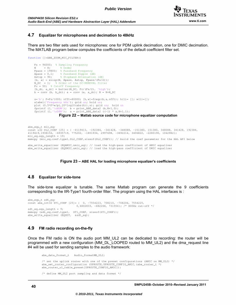
40
Public Version
OMAP4430 Silicon Revision ES2.x Audio Back-End (ABE) and Hardware Abstraction Layer (HAL) Addendum
SWPU245B–October 2010–Revised January 2011
www.ti.com
© 2010-2011, Texas Instruments Incorporated
4.7 Equalizer for microphones and decimation to 48kHz
There are two filter sets used for microphones: one for PDM uplink decimation, one for DMIC decimation. The MATLAB program below computes the coefficients of the default coefficient filter set. function []=ABE_ZOOM_MIC_FILTER() Fs = 96000; % Sampling Frequency N = 8; % Order Fpass = 19800; % Passband Frequency Apass = 0.1; % Passband Ripple (dB) Astop = 90; % Stopband Attenuation (dB) [b, a] = ellip(N, Apass, Astop, Fpass/(Fs/2)); N_DC = 1; % Order of the DC-REMOVAL filter Fc = 50; % Cutoff Frequency [b_dc, a_dc] = butter(N_DC, Fc/(Fs/2), 'high'); b = conv (b, b_dc); a = conv (a, a_dc); N = N+N_DC s='b'; F=Fs/1000; nfft=80000; [h,w]=freqz(b,a,nfft); h(1)= []; w(1)=[]; xlabel('Frequency kHz'); grid on; hold on; plot (0.5*F*w/pi,20*log10(abs(h)),s); grid on; hold on fprintf (1,'\nNUM'); b = print_ABE_data2 (b,N+1,0); fprintf (1,'\nDEN'); a = print_ABE_data2 ((-1) * a,N+1,1);
Figure 22 – Matlab source code for microphone equalizer computation
abe_equ_t mic_eq; const u32 DL2_COEF [25] = { -4119413, -192384, -341428, -348088, -151380, 151380, 348088, 341428, 192384, 4119419,1938156, -6935719, 775202, -1801934, 2997698, -3692214, 3406822, -2280190, 1042982}; mic_eq.equ_length = 19; memcpy (mic_eq.coef.type1,DL2_COEF,sizeof(DL2_COEF)); // build the coef parameter for the HAL API below abe_write_equalizer (EQAMIC,&mic_eq); // load the high-pass coefficient of AMIC equalizer abe_write_equalizer (EQDMIC,&mic_eq); // load the high-pass coefficient of DMIC equalizer
Figure 23 – ABE HAL for loading microphone equalizer's coefficients
4.8 Equalizer for side-tone
The side-tone equalizer is tunable. The same Matlab program can generate the 9 coefficients corresponding to the IIR-Type1 fourth-order filter. The program using the HAL interfaces is : abe_equ_t sdt_eq; const abe_int32 ST1_COEF [25]= { 0, -7554223, 708210, -708206, 7554225, 0,6802833, -682266, 731554}; /* 800Hz cut-off */ sdt_eq.equ_length = 9; memcpy (sdt_eq.coef.type1, ST1_COEF, sizeof(ST1_COEF)); abe_write_equalizer (EQSDT, &sdt_eq);
4.9 FM radio recording on-the-fly
Once the FM radio is ON the audio port MM_UL2 can be dedicated to recording: the router will be programmed with a new configuration (MM_DL_LOOPED routed to MM_UL2) and the dma_request line #4 will be used for sending samples to the audio framework:
abe_data_format_t Audio_formatMM_UL2; /* set the uplink router with one of the preset configurations (AMIC on MM_UL2) */ abe_set_router_configuration (UPROUTE,UPROUTE_CONFIG_AMIC,(abe_router_t *) abe_router_ul_table_preset[UPROUTE_CONFIG_AMIC]); /* define MM_UL2 port sampling and data format */

SWPU245B–October 2010–Revised January 2011
41
www.ti.com OMAP4430 Silicon Revision ES2.x
Audio Back-End (ABE) and Hardware Abstraction Layer (HAL) Addendum
© 2010-2011, Texas Instruments Incorporated
Public Version
Audio_formatMM_UL2.f = 48000; Audio_formatMM_UL2.samp_format = STEREO_MSB; /* compute the address to be used by the sDMA for reading the MM_UL2 samples */ abe_connect_cbpr_dmareq_port (MM_UL2_PORT,&Audio_formatMM_UL2,ABE_CBPR4_IDX,&ABE_CBPR_MM_UL2); /* enable MM_UL2 (AMIC path is supposed to have been initialized) */ abe_enable_data_transfer (MM_UL2_PORT );
4.10 AE processing - Drift management
AESS has two schemes to adapt to the data rates:
a. tuning the 10μs scheduling period to the rate of one port. b. using Asynchronous Sample-Rate Converters. Those ASRC are placed on VX_UL and VX_DL
Modem voice paths, BT_VX_UL and BT_VX_DL voice paths, and MM_EXT_IN multimedia path. The selection of the port of scheme a) is based on the following algorithm:
The first abe port enabled of the table below which is not using Ping-Pong or sDMA requests will be selected as source of time synchronization : [ PDM_DL_PORT, PDM_UL_PORT, MM_EXT_OUT_PORT, MM_EXT_IN_PORT, TDM_DL_PORT, TDM_UL_PORT, DMIC_PORT, MM_UL_PORT, MM_UL2_PORT, MM_DL_PORT, TONES_DL_PORT, VX_UL_PORT, VX_DL_PORT, BT_VX_DL_PORT, BT_VX_UL_PORT, VIB_DL_PORT ]
This scheme can be changed based on the priority table "abe_port_priority[]" located in the abe_dat.c file.
4.11 Serial ports FIFO thresholds
The McBSP FIFO threshold must be aligned with the programmation of the associated logical port following the table below:
Data format Number of words per McBSP DMA requests MONO_MSB 1 MONO_RSHIFTED_16 1 STEREO_RSHIFTED_16 2 STEREO_16_16 1 STEREO_MSB 2
Table 11 : McBSP thresholds
4.12 Audio Clicks
There are two types of audio “clicks”: the ones resulting from a signal discontinuity created in the analog domain, and the ones resulting from a signal discontinuity created in the digital domain. TI hardware (OMAP4 - ABE-TWL6040) is designed in order not to create any “analog clicks”. The audio, PRCM and DMA hardware must be controlled following a documented programming sequence in order to avoid the “pops” and “clicks”. The paragraph "TWL6040 PDM interface clock, states transitions " gives the programming sequences. Because of the software integration complexity in the operating system, some errors may happen. The errors are most often occurring in the beginning or the end of the audio streams.

42
Public Version
OMAP4430 Silicon Revision ES2.x Audio Back-End (ABE) and Hardware Abstraction Layer (HAL) Addendum
SWPU245B–October 2010–Revised January 2011
www.ti.com
© 2010-2011, Texas Instruments Incorporated
“Digital clicks” can result from various sources of real-time system issues:
- CPU overload. CPU load varies depending on concurrent use-cases. The sizes of the intermediate buffers can be computed in order to cope with the maximum CPU load jitter. The CPU must implement a starving detector that will proceed to a smoothed channel shut-down. - sDMA channels with wrong priorities. OMAP4 sDMA holds several channels in order not block one data transfer because of others. Audio DMA bursts are always small and should be treated by the programmer as having a high priority.
ABE firmware will implement a detector of sDMA real-time issue when used for ABE Ping-Pong and “ATC/CBPr” protocols. ABE firmware will repeat the last sample used before the issue. This solution will unfortunately create also a “click”.

SWPU245B–October 2010–Revised January 2011
43
www.ti.com OMAP4430 Silicon Revision ES2.x
Audio Back-End (ABE) and Hardware Abstraction Layer (HAL) Addendum
© 2010-2011, Texas Instruments Incorporated
Public Version
4.13 Use-Case transitions
4.13.1 Opening and closing ports – start/stop code sequence OMAP4 ES2.x devices have a limitation described as "OMAP4430-1.0BUG00820". This bug obliges to program the AE logical ports and there corresponding serial-interfaces physical ports in a pre-defined order: START sequences: The AE logical port is programmed with the API abe_connect_serial_port(). PDM_DL/UL and DMIC serial interfaces do not need to be programmed because the configuration is always the same. Then the following sequence must be applied:
1) start AESS ports : HAL API "abe_enable_data_transfer()" 2) wait 250µs 3) start the serial ports : call the device driver of McPDM, DMIC or McBSP1/2/3.
STOP sequences:
1) stop the AESS ports : HAL API "abe_disable_data_transfer()" 2) wait 250µs 3) stop the serial ports : call the device driver of McPDM, DMIC or McBSP1/2/3.
4.13.2 OPP transitions Three level of voltage and clock configurations can be managed in AESS:
- OPP25% : AE processing clock is 49.152MHz, event generator period is 10.4167μs or 11.338μs - OPP50% : AE processing clock is 98.304MHz, event generator period is 10.4167μs - OPP100% : AE processing clock is 196.608MHz, event generator period is 10.4167μs
The decision the switch from one OPP to another must be based on the type of use-cases. In the previous pictures "Processing flow with OPP values …" the OPP level is given through a color code. In order not to create a dependency between the HAL/FW implementation (some colors may change based on later code optimizations and new features implementations) and the upper software layers, it is mandatory to use the HAL API "abe_read_use_case_op()". Software portability can only be guaranteed with API. This API returns the OPP level for a given list of active use-case. Once the OPP level is known the PRCM clock and voltage can be changed (abe_set_opp_processing()).

44
Public Version
OMAP4430 Silicon Revision ES2.x Audio Back-End (ABE) and Hardware Abstraction Layer (HAL) Addendum
SWPU245B–October 2010–Revised January 2011
www.ti.com
© 2010-2011, Texas Instruments Incorporated
OPP 25%
OPP 100%
OPP 50%PRCM is set afterABE HAL OPP is set
PRCM is set beforeABE HAL OPP is set
Figure 24 – OPP transitions
4.13.3 TWL6040 transitions TWL6040 transitions can be managed with state machines located in an audio configuration manager. With 7 states we have many are transitions possibility on the headset path, which is not testable and practical. The proposal is to always go through an "idle" state, which now limits the available transitions to 5, as seen in picture below. TWL6040 D/A accuracy can be set to 3 or 4 bits (LP/HP mode), independently to the type of clock (32kHz or MCLK). The programming transitions from Idle state to 32kHz or MCLK is transparent.

SWPU245B–October 2010–Revised January 2011
45
www.ti.com OMAP4430 Silicon Revision ES2.x
Audio Back-End (ABE) and Hardware Abstraction Layer (HAL) Addendum
© 2010-2011, Texas Instruments Incorporated
Public Version
Figure 25 – Headset / Earphone transitions The Headset and Earphones states are :
- OFF : power and clock shut down - IDLE : D/A and drivers enabled in LP mode 48kHz, ABE sends zeros to the modulator. - LP modes : D/A are using 3bits - HP modes : D/A are using 4 bits
The ABE gains (GAINS_DL1 / GAINS_DL2) must be set accordingly the D/A operations:
- 3 bits operations : set the desired gain with 6dB attenuation abe_write_gain (GAINS_DL1,GAIN_M6dB , RAMP_100MS, GAIN_LEFT_OFFSET); // LP, 3bits D/A abe_write_gain (GAINS_DL1,GAIN_M6dB , RAMP_100MS, GAIN_RIGHT_OFFSET); // LP, 3bits D/A
- 4 bits operations : set the desired gain (without compensation)
abe_write_gain (GAINS_DL1,GAIN_0dB , RAMP_100MS, GAIN_LEFT_OFFSET); // HP, 4bits D/A abe_write_gain (GAINS_DL1,GAIN_0dB , RAMP_100MS, GAIN_RIGHT_OFFSET); // HP, 4bits D/A
There are 5 transitions possible with the described programming sequences:
4.13.3.1 OFF -> IDLE : - ABE-HAL audio port (PDM_DL) activated - ABE-HAL Gain DL1 set to 0 (mute) - Wait at least 250μs or poll the ATC(on) bit - OMAP-MCPDM IP activated - TWL6040 D/A enabled and PDM clock is enabled - TWL6040 headset / earphone driver enabled
IDLE -> OFF :
- TWL6040 headset / earphone driver disabled - TWL6040 D/A disabled and PDM clock is disabled - ABE-HAL audio port (PDM_DL) disabled - Wait at least 250μs or poll the ATC(off) bit - OMAP-MCPDM IP disabled
4.13.3.2 IDLE -> 48kHz LP-32kHz This transition consists in simple ABE-HAL call because TWL6040 is already in the correct state:
- ABE-HAL called to restore the nominal gain minus 6dB 48kHz LP-32kHz -> IDLE :
- ABE-HAL called to set the gain to 0 (mute)
4.13.3.3 IDLE -> 48kHz LP-MCK - ABE-HAL called to restore the nominal gain minus 6dB - PLL clock switching from 32kHz to MCLK
48kHz LP-MCLK -> IDLE :
- ABE-HAL called to set the gain to 0 (mute) - PLL clock switching from MCLK to 32kHz
4.13.3.4 IDLE -> 44.1kHz LP-32kHz : The PLL of TWL6040 needs to be tuned.
- LPLLDIV register of TWL6040 needs to be set for 44.1kHz sampling - ABE-HAL called to restore the nominal gain minus 6dB - ABE-HAL called to set the event generator to 44.1kHz

46
Public Version
OMAP4430 Silicon Revision ES2.x Audio Back-End (ABE) and Hardware Abstraction Layer (HAL) Addendum
SWPU245B–October 2010–Revised January 2011
www.ti.com
© 2010-2011, Texas Instruments Incorporated
44.1kHz LP-32kHz -> IDLE :
- ABE-HAL called to set the gain to 0 (mute) - LPLLDIV register of TWL6040 needs to be set for 48Hz sampling - ABE-HAL called to set the event generator to 48kHz
4.13.3.5 IDLE -> 48kHz HP-32kHz : This transition consists in simple ABE-HAL, TWL6040 need to go to 4bits :
- TWL6040 D/A set to 4 bits mode - ABE-HAL called to restore the nominal gain
48kHz HP-32kHz -> IDLE :
- ABE-HAL called to set the gain to 0 (mute) - TWL6040 D/A set to 3 bits mode
4.13.3.6 IDLE -> 48kHz HP-MCLK : This transition consists switching both the D/A and clock configuration
- TWL6040 clock selected mode to MCLK - TWL6040 D/A set to 4 bits mode - ABE-HAL called to restore the nominal gain
48kHz HP-MCLK -> IDLE :
- ABE-HAL called to set the gain to 0 (mute) - TWL6040 D/A set to 3 bits mode - TWL6040 clock selected mode to 32kHz
4.13.3.7 Hands-free transitions : The Hands-free states are :
- OFF : power and clock shut down - IDLE : D/A and drivers enabled, ABE sends zeros to the modulator. - LP modes : D/A are using 3bits
There are 3 transitions possible :
Figure 26 – Hands-free transitions

SWPU245B–October 2010–Revised January 2011
47
www.ti.com OMAP4430 Silicon Revision ES2.x
Audio Back-End (ABE) and Hardware Abstraction Layer (HAL) Addendum
© 2010-2011, Texas Instruments Incorporated
Public Version
4.13.3.8 TWL6040 PDM interface clock, states transitions : The OMAP-MCPDM IP needs the PDM clock to be enabled. This PDM clock is generated by the TWL6040 and will be activated as soon as one of the A/D and D/A feature is activated:
Figure 27 – PDM states transitions
4.13.3.9 Clocks transitions : TWL6040 clock transitions between MCLK and CLK-32kHz have no impact on AESS.
CLK 32kHz
MCLK
Figure 28 – TWL6040 clocks tree and transitions
4.13.3.10 Microphones transitions : The first samples of an A/D conversion are noisy and have high DC level, they must be skipped and replaced by null samples. The HAL ports must be enabled before the IP is enabled. The HAL port must disabled before the IP is disabled, in order to be sure some pending samples exchanged in the local L4 AESS interconnect to be finished correctly.
AMIC OFF -> AMIC: - ABE-HAL GAINS_AMIC set to mute and programmed with a ramp to nominal gain - Enable PDM clock and TWL6040 A/D path - ABE-HAL called enable the ports (PDM_UL_PORT)

48
Public Version
OMAP4430 Silicon Revision ES2.x Audio Back-End (ABE) and Hardware Abstraction Layer (HAL) Addendum
SWPU245B–October 2010–Revised January 2011
www.ti.com
© 2010-2011, Texas Instruments Incorporated
- Wait at least 250μs or poll the ATC(on) bit - Enable the OMAP MCPDMUL IP
DMIC OFF -> DMIC : - ABE-HAL GAINS_DMIC(x) set to mute and programmed with a ramp to nominal gain - TWL6040 set the power of DMIC (MIC VBIAS) - ABE-HAL called enable the ports (DMIC_PORT) - Wait at least 250μs or poll the ATC(on) bit - Enable the OMAP DMIC IP
AMIC -> AMIC OFF:
- ABE-HAL GAINS_AMIC set to mute - ABE-HAL disables the port (PDM_UL_PORT) - Wait at least 250μs or poll the ATC(off) bit - Disable the OMAP MCPDMUL IP - Shut down PDM clock and TWL6040 A/D path
DMIC -> DMIC OFF: - ABE-HAL GAINS_DMIC set to mute - ABE-HAL disables the port (DMIC_PORT) - Wait at least 250μs or poll the ATC(off) bit - Disable the OMAP DMIC IP - Shut down DMIC clock and TWL6040 DMIC bias
Figure 29 – Microphones transitions
4.13.3.11 TWL6040 Power Down condition TWL6040 goes in OFF mode when all the below conditions are reached:
- AMIC is OFF - DMIC is OFF - VIB is OFF - HS/EAR is in OFF - IHF is OFF

SWPU245B–October 2010–Revised January 2011
49
www.ti.com OMAP4430 Silicon Revision ES2.x
Audio Back-End (ABE) and Hardware Abstraction Layer (HAL) Addendum
© 2010-2011, Texas Instruments Incorporated
Public Version
Figure 30 – TWL6040 Power-Down conditions
4.13.3.12 Gain values to apply with respect of the TWL6040 configuration This downlink gains (DL1/DL2) must be adjusted with respect of the configuration of the respective D/A. The table below gives the recommended attenuation to set in the ABE :
Path AESS Gain HS DAC HP 0dB HS DAC LP -8.2dB EAR DAC HP -1dB EAR DAC LP -9dB HF DAC LP -7dB
Table 12 : Maximum gains to set in downlink paths DL1 / DL2

50
Public Version
OMAP4430 Silicon Revision ES2.x Audio Back-End (ABE) and Hardware Abstraction Layer (HAL) Addendum
SWPU245B–October 2010–Revised January 2011
www.ti.com
© 2010-2011, Texas Instruments Incorporated
5 Debugging ABE This section gives some advices for debugging audio on top of the existing HAP APIs abe_connect_debug_trace and abe_enable_test_pattern.
5.1 FIFO locations
ATC FIFOs are located in DMEM (L3 base address 0x4908.0000). The ATC descriptors are located at addressed (DMA_req index x 8bytes). For example the CBPr0 (MM_DL) descriptor is located at the DMEM offset 32x8 = 256, the physical address is 0x4908.0100.
DMA input Source Description
DMA_1 DMIC_DMA_REQ Transmit request digital microphone DMA_2 McPDM_DMA_DL Multichannel PDM downlink DMA_3 McPDM_DMA_UP Multichannel PDM uplink DMA_4 MCBSP1_DMA_TX MCBSP module 1 - transmit request DMA_5 MCBSP1_DMA_RX MCBSP module 1 - receive request DMA_6 MCBSP2_DMA_TX MCBSP module 2 - transmit request DMA_7 MCBSP2_DMA_RX MCBSP module 2 - receive request DMA_8 MCBSP3_DMA_TX MCBSP module 3 - transmit request DMA_9 MCBSP3_DMA_RX MCBSP module 3 - receive request DMA_14 SLIMBUS1_DMA_TX4 SLIMBUS module 1 – transmit request channel 4 DMA_15 SLIMBUS1_DMA_TX5 SLIMBUS module 1 – transmit request channel 5 DMA_16 SLIMBUS1_DMA_TX6 SLIMBUS module 1 – transmit request channel 6 DMA_17 SLIMBUS1_DMA_TX7 SLIMBUS module 1 – transmit request channel 7 DMA_22 SLIMBUS1_DMA_RX4 SLIMBUS module 1 – receive request channel 4 DMA_23 SLIMBUS1_DMA_RX5 SLIMBUS module 1 – receive request channel 5 DMA_24 SLIMBUS1_DMA_RX6 SLIMBUS module 1 – receive request channel 6 DMA_25 SLIMBUS1_DMA_RX7 SLIMBUS module 1 – receive request channel 7 DMA_32 CBPr_DMA_RTX0 DMA of the Circular buffer peripheral 0 DMA_33 CBPr_DMA_RTX1 DMA of the Circular buffer peripheral 1 DMA_34 CBPr_DMA_RTX2 DMA of the Circular buffer peripheral 2 DMA_35 CBPr_DMA_RTX3 DMA of the Circular buffer peripheral 3 DMA_36 CBPr_DMA_RTX4 DMA of the Circular buffer peripheral 4 DMA_37 CBPr_DMA_RTX5 DMA of the Circular buffer peripheral 5 DMA_38 CBPr_DMA_RTX6 DMA of the Circular buffer peripheral 6 DMA_39 CBPr_DMA_RTX7 DMA of the Circular buffer peripheral 7
Table 13 : ATC DMA requests
With this example, CBPr0 FIFO should points to the address of "D_MM_DL_FIFO" which starts at 0x4908.1600 and ends at 0x4908.17DF (480 bytes).
Size (bytes) OFFSET(HEX) ATC FIFOs 512 0x0 D_atcDescriptors 480 0x400 D_BT_DL_FIFO 480 0x600 D_BT_UL_FIFO 480 0x800 D_MM_EXT_OUT_FIFO

SWPU245B–October 2010–Revised January 2011
51
www.ti.com OMAP4430 Silicon Revision ES2.x
Audio Back-End (ABE) and Hardware Abstraction Layer (HAL) Addendum
© 2010-2011, Texas Instruments Incorporated
Public Version
480 0xA00 D_MM_EXT_IN_FIFO 480 0xC00 D_MM_UL2_FIFO 480 0xE00 D_VX_UL_FIFO 480 0x1000 D_VX_DL_FIFO 480 0x1200 D_DMIC_UL_FIFO 480 0x1400 D_MM_UL_FIFO 480 0x1600 D_MM_DL_FIFO 480 0x1800 D_TONES_DL_FIFO 480 0x1A00 D_VIB_DL_FIFO 480 0x1C00 D_McPDM_DL_FIFO 480 0x1E00 D_McPDM_UL_FIFO
Table 14 : ATC FIFO DMEM offset Some basic checks can be made looking at addresses given in the HAL file "ABE_DM_ADDR.h":
- the version number of the firmware (DMEM offset "D_version_ADDR") - the firmware counter of 4kHz periods (DMEM offset "D_loopCounter_ADDR")
And also the DL1/DL2 mixers' gains (CMEM offset "C_Gains_DL1M" and "C_Gains_DL2M_ADDR"). CMEM L3 base address is 0c490A.0000 The sDMA masks can be checked at address AESS_DMAENABLE_SET (0x490F.1060). Once the sDMA is set a DMA request can be generated writing at address AESS_DMASTATUS_RAW (0x490F.1084), and DMA transfer with the ATC FIFO in DMEM should be seen.
5.2 Debug trace
The real-time debug trace consist in connecting the 8th ABE DMA request to the sDMA. On every 4kHz periods the sDMA will read a buffer of 128bytes from DMEM. The API "abe_connect_debug_trace" returns the physical address and size of each transfer. The debug buffer is not a ping-pong buffer, sDMA will always start reading from the same DMEM offset (D_debugATCptrs_ADDR). The debug trace buffer is organized as below
- offset 0: time stamp in 250μs unit (scheduler periods) - offset 4bytes: list of the 16 ATC read and write pointers respectively corresponding to :
MCPDM_UL, BT_VX_UL, MM_UL, MM_UL2, VX_UL, MM_DL, VX_DL, TONES_DL, VIB_DL, BT_VX_DL, PDM_DL, MM_EXT_OUT, MM_EXT_IN, TDM_OUT, TDM_IN.
- offset 36 bytes: HAL APIs data

52
Public Version
OMAP4430 Silicon Revision ES2.x Audio Back-End (ABE) and Hardware Abstraction Layer (HAL) Addendum
SWPU245B–October 2010–Revised January 2011
www.ti.com
© 2010-2011, Texas Instruments Incorporated
IMPORTANT NOTICE
Texas Instruments Incorporated and its subsidiaries (TI) reserve the right to make corrections, modifications, enhancements, improvements, and other changes to its products and services at any time and to discontinue any product or service without notice. Customers should obtain the latest relevant information before placing orders and should verify that such information is current and complete. All products are sold subject to TI’s terms and conditions of sale supplied at the time of order acknowledgment. TI warrants performance of its hardware products to the specifications applicable at the time of sale in accordance with TI’s standard warranty. Testing and other quality control techniques are used to the extent TI deems necessary to support this warranty. Except where mandated by government requirements, testing of all parameters of each product is not necessarily performed. TI assumes no liability for applications assistance or customer product design. Customers are responsible for their products and applications using TI components. To minimize the risks associated with customer products and applications, customers should provide adequate design and operating safeguards. TI does not warrant or represent that any license, either express or implied, is granted under any TI patent right, copyright, mask work right, or other TI intellectual property right relating to any combination, machine, or process in which TI products or services are used. Information published by TI regarding third-party products or services does not constitute a license from TI to use such products or services or a warranty or endorsement thereof. Use of such information may require a license from a third party under the patents or other intellectual property of the third party, or a license from TI under the patents or other intellectual property of TI. Reproduction of TI information in TI data books or data sheets is permissible only if reproduction is without alteration and is accompanied by all associated warranties, conditions, limitations, and notices. Reproduction of this information with alteration is an unfair and deceptive business practice. TI is not responsible or liable for such altered documentation. Information of third parties may be subject to additional restrictions. Resale of TI products or services with statements different from or beyond the parameters stated by TI for that product or service voids all express and any implied warranties for the associated TI product or service and is an unfair and deceptive business practice. TI is not responsible or liable for any such statements. TI products are not authorized for use in safety-critical applications (such as life support) where a failure of the TI product would reasonably be expected to cause severe personal injury or death, unless officers of the parties have executed an agreement specifically governing such use. Buyers represent that they have all necessary expertise in the safety and regulatory ramifications of their applications, and acknowledge and agree that they are solely responsible for all legal, regulatory and safety-related requirements concerning their products and any use of TI products in such safety-critical applications, notwithstanding any applications-related information or support that may be provided by TI. Further, Buyers must fully indemnify TI and its representatives against any damages arising out of the use of TI products in such safety-critical applications. TI products are neither designed nor intended for use in military/aerospace applications or environments unless the TI products are specifically designated by TI as military-grade or "enhanced plastic." Only products designated by TI as military-grade meet military specifications. Buyers acknowledge and agree that any such use of TI products which TI has not designated as military-grade is solely at the Buyer's risk, and that they are solely responsible for compliance with all legal and regulatory requirements in connection with such use. TI products are neither designed nor intended for use in automotive applications or environments unless the specific TI products are designated by TI as compliant with ISO/TS 16949 requirements. Buyers acknowledge and agree that, if they use any non-designated products in automotive applications, TI will not be responsible for any failure to meet such requirements. Following are URLs where you can obtain information on other Texas Instruments products and application solutions: Products Applications Amplifiers amplifier.ti.com Audio www.ti.com/audio Data Converters dataconverter.ti.com Automotive www.ti.com/automotive DLP® Products www.dlp.com Communications & Telecom www.ti.com/communications DSP dsp.ti.com Computers & Peripherals www.ti.com/computers Clocks and Timers www.ti.com/clocks Consumer Electronics www.ti.com/consumer-apps Interface interface.ti.com Energy www.ti.com/energyapps Logic logic.ti.com Industrial www.ti.com/industrial Power Mgmt power.ti.com Medical www.ti.com/medical Microcontrollers microcontroller.ti.com Security www.ti.com/security RFID www.ti-rfid.com Space, Avionics & Defense www.ti.com/space-avionics-defense RF/IF and ZigBee® Solutions www.ti.com/lprf Video & Imaging www.ti.com/video Wireless www.ti.com/wireless-apps
TI E2E Community Home Page e2e.ti.com Mailing Address: Texas Instruments, Post Office Box 655303, Dallas, Texas 75265 Copyright 2010, Texas Instruments Incorporated