
OM, PRO 35 65 III Electric Diesel, 2001-05, 0A7846 · • Triángwulo De Advertencia • Wear Eye...
46
0A7846 Copyright © May 2001, Diamant Boart, Inc. Printed in U.S.A. PRO 35 III DIESEL PRO 35 III ELECTRIC PRO 65 III DIESEL STANDARD MODELS OPERATING INSTRUCTIONS INSTRUCCIONES DE OPERACIÓN 17400 W. 119 th Street Olathe, Kansas 66061, USA Customer Service ........ 800-288-5040 Corporate Office .......... 913-928-1000 Cust. Service Fax ........ 800-825-0028 Corporate Office Fax... 913-438-7951 Int’l. Fax ........................ 913-438-7938 Internet ..... http://www.targetblue.com
Transcript of OM, PRO 35 65 III Electric Diesel, 2001-05, 0A7846 · • Triángwulo De Advertencia • Wear Eye...

1
0A7846Copyright © May 2001, Diamant Boart, Inc.Printed in U.S.A.
PRO 35 III DIESELPRO 35 III ELECTRICPRO 65 III DIESELSTANDARD MODELS
OPERATING INSTRUCTIONSINSTRUCCIONES DE OPERACIÓN
17400 W. 119th StreetOlathe, Kansas 66061, USA
Customer Service ........ 800-288-5040Corporate Office .......... 913-928-1000Cust. Service Fax ........ 800-825-0028Corporate Office Fax ... 913-438-7951Int’l. Fax ........................ 913-438-7938Internet ..... http://www.targetblue.com

2
EVERY MACHINE IS THOROUGHLY TESTED BEFORE LEAVING THE FACTORY. EACH MACHINEIS SUPPLIED WITH A COPY OF THIS MANUAL. OPERATORS OF THIS EQUIPMENT MUST READ AND BEFAMILIAR WITH THE SAFETY WARNINGS. FAILURE TO OBEY WARNINGS MAY RESULT IN INJURY ORDEATH. FOLLOW INSTRUCTIONS STRICTLY TO ENSURE LONG SERVICE IN NORMAL OPERATION.
Table of ContentsCONTENTS ................................................................................................................................ PAGE NO.Symbol Definitions .................................................................................................................................................... 4Decal Descriptions And Locations ............................................................................................................................. 9Saw Dimensions ...................................................................................................................................................... 11PRO 65 III Diesel Specifications ............................................................................................................................. 12PRO 35 III Diesel Specifications ............................................................................................................................. 13PRO 35 III 20HP Electric Specifications .................................................................................................................. 14Power Source ........................................................................................................................................................ 15Special Instructions For Changing Blade Speed On Concrete / Asphalt Saws ........................................................... 16WARNINGS............................................................................................................................................................ 18
FIGURESFIG. 1 ..................................................................................................................................................................... 20FIG. 2 ..................................................................................................................................................................... 21FIG. 3 ..................................................................................................................................................................... 21FIG. 4 ..................................................................................................................................................................... 22FIG. 5 ..................................................................................................................................................................... 28
Pre Operation Checklist .......................................................................................................................................... 23Scheduled Maintenance Quick Reference ............................................................................................................... 23
INSTRUCTIONS 1 Use ................................................................................................................................................................ 24 2 Moving The Machine ...................................................................................................................................... 24 3 Transport (Blade Removed) ............................................................................................................................ 25 4 Check Before Starting .................................................................................................................................... 25 5 Fitting The Blade ............................................................................................................................................ 25 6 Starting The Saw ............................................................................................................................................ 26 7 Stopping The Saw .......................................................................................................................................... 27 8 Incidents During Sawing ................................................................................................................................ 27 9 Adjustments: Straight Line Sawing ................................................................................................................. 2710 Maintenance .................................................................................................................................................. 2711 Bladeshaft V-Belt And Jackshaft Belt Tension .................................................................................................. 2812 Hydraulic System ........................................................................................................................................... 3013 Parking Brake (Optional) ................................................................................................................................ 3014 Important Advice ............................................................................................................................................ 3015 Pro 35III Electric saws ................................................................................................................................... 3016 Accessories ................................................................................................................................................... 3117 Metric Hardware ............................................................................................................................................ 3218 Repairs .......................................................................................................................................................... 3219 Spare Parts.................................................................................................................................................... 32
PRO 35 III Diesel Blade Size Conversion Chart ....................................................................................................... 34PRO 65 III Diesel Blade Size Conversion Chart ....................................................................................................... 35
DIAGRAMSDiagram 1 - Wiring Diagram - PRO 35 III Diesel, 182127 ........................................................................................ 36Diagram 2 - Wiring Diagram - PRO 65 III Diesel, 182139 ........................................................................................ 38Diagram 3 - Ladder Diagram - PRO 35 III Diesel and PRO 65 III Diesel, 182121 ..................................................... 40Diagram 4 - Wiring Diagram - PRO 35 III Electric, 182062...................................................................................... 42Diagram 5 - PRO 35 III Electric Wiring Instructions ................................................................................................. 44Diagram 6 - Ladder Diagram - PRO 35 III Electric, 182068 ..................................................................................... 45

3

4
Symbol DefinitionsDefinición De Los Simbolos
• Please read the instructions for use prior to operating the machine for the first time.• Antes de la puesta en marcha, lea detenidamente las instrucciones y familiaricese con la máquina.
• Mandatory• Obligatorio
• Indication• Indicación
• Prohibition• Prohibición
• Warning Triangle• Triángwulo De Advertencia
• Wear Eye Protection• Usar Gafas De Protección
• Wear Head Protection• Usar Casco De Protección
• Wear Breathing Protection• Usar Máscara De Protección
• The Use Of Ear Protection Is Mandatory• Es Obligatorio El Uso De Protección Auditiva
• Wear a Hard Hat• Usar Casco Duro
• Wear Safety Shoes• Usar Zapatos De Seguridad
• Wear Appropriate Clothing• Usar Ropa Adecuada
• Remove The Blade Prior To Hoisting, Loading, Unloading And Transporting The Machine On Jobsite.• Desmontar El Disco Antes De Desplazar, Cargar, Descargar O Transportar La Máquina En La Obra.

5
• Motor Off• Parar El Motor
• Use In Well Ventilated Area• Usar En Una Área Bien Ventilada
• Do Not Use In Flammable Areas• No Usar In Áreas Inflamables
• Machinery Hazard, Keep Hands And Feet Clear.• Máquina Peligrosa - Mantenga Manos Y Pies Alejados De La Máquina
• Danger, Poison Exhaust Gas• Peligro, Gases De Escape Tóxicos
• No Non-working Personnel In Area• Prohibido Para Personas Ajenas A La Obra
• No Smoking• No Fumar
• Do Not Operate Without All Guards In Place• No Operar Sin Todas Las Protecciones In Su Sitio
• Always Keep the Blade Guards In Place• Mantenga Siempre Las Protecciones De La Hoja En Su Sitio
• Water Supply On.• Suministro De Agua Conectado.
• Water Supply Off• Suministro De Agua Desconectado
• Water Supply• Suministro De Aguq
• Water Safety Switch-Press to Reset if Water Supply Interrupted• Si Se Ha Interrumpido El Suministro De Agua, Pulsar El Conmutador De Seguridad De Agua Para
Reposicionarlo.
• Coolant Temperature• Temperatura Del Líquido Refrigerante

6
• Keep Work Area Clean/Well Lit, Remove All Safety Hazards• Mantenga Limpio El Sitio De Trabajo/Bien Iluminado, Elimine Todos Los Riesgos De Seguridad
• Dangerously High Noise Level• Nivel De Ruido Elevadamente Peligroso
• Pay Extreme Attention To The Care And Protection Of The Machine Before Starting Up• Ponga Extrema Atención Al Cuidado Y Preparación De La Máquina Antes De Ponerla En Marcha
• Remove Tools From Area and Machine• Elimine Las Herramientas Del Área Y De La Máquina
• Oil Pressure• Presion De Aceite
• Oil Required• Necesita Aceite
• Dipstick, Maintain Proper Oil Level• Varilla De Control, Mantenga El Nivel De Aceite Correcto
• Lubrication Point• Punto De Lubrication
• Unleaded Fuel Only• Solamente Combustible Sin Plomo
• High Range Travel Speed• Alta Velocidad De Avance
• Low Range Travel Speed• Baja Velocidad De Avance
• Electrical Switch - OFF• Conmutador De Apagado Eléctrico
• Electrical Switch - ON• Conmutador De Encendido Eléctrico
• Electrical Switch - Start• Conmutador De Arranque Eléctrico
• Repairs Are To Be Done By An Authorized Dealer Only• Las Reparaciones Deben Ser Efectuadas Únicamente Por Un Distribuidor Autorizado

7
• Headlight• Luz De Cruce
• Diamond Blade• Sierra Diamantada
• Blade Diameter• Diámetro De La Hoja
• Blade Engagement• Acoplamiento De La Hoja
• Pulley Diameter• Diámetro De La Correa
• Number of Revolutions Per Minute, Rotational Speed• N° De Revoluciones Por Minuto, Velocidad De Rotación
• Blade Flange Diameter• Diámetro De La Brida De La Hoja
• Blade Depth Stop• Tope De Profundidad De La Hoja
• Blade Cutting Depth• Profundidad De Corte De La Hoja
• Parking Brake• Freno De Estacionamiento
• Parking Brake Applied• Freno De Estacionamiento Aplicado
• Parking Brake Released• Freno De Estacionamiento Suelto
• Machine Mass (lbs)• Masa De La Máquina (lbs)
• Positive Battery Terminal• Terminal Positivo De Batería
• Blade Indicator -Zero• Indicador De Cero De La Hoja

8
WARNINGHEARING HAZARD
DURING NORMAL USE OF THIS MACHINE, OPERATOR MAY BE EXPOSED TO A NOISE LEVEL EQUAL OR SUPERIOR TO 85 dB (A)
ATENCIONRIESGO DE DAÑO AUDITIVO
EN CONDICIONES NORMALES DE UTILIZACIÓN, EL OPERADOR DE ESTA MÁQUINA PUEDEESTAR EXPUESTO A UN NIVEL DE RUIDO IGUAL O SUPERIOR A 85 dB (A)
• Electric Motor• Motor eléctrico
• Engine• Motor
• Engine Speed Revolutions/Minute• Velocidad Del Motor En Revoluciones Por Minuto (RPM)
• Engine Start• Arranque Del Motor

9
DECAL DESCRIPTIONS AND LOCATIONSDESCRIPCIÓN DE CALCAMONIAS Y UBICACIONES
DEPTH STOP: TOP OF COWLP/N 163233 (All Models)
O
O
l l
INSTRUMENT PANELP/N 191028 (PRO 65 III Diesel)
P/N 191006 (PRO 35 III Diesel - Shown)P/N 191127 (PRO 35 III Electric)
123
4
5
6
7
89
10 1112
48
12
16
20
24 28 32
0
00 0
cm in
DEPTH INDICATORP/N 191308 (PRO 65 III Diesel)
P/N 191009 (PRO 35 III Diesel/Electric - Shown)
WARNING:1) Rear of Cowl above opening to transmission, Top of Frame2) Left Side of Engine by Lift Bail Mount
P/N 176223 (Quantity 2, All Models)
OPERATING INSTRUCTIONS, TOP OF COWLP/N 191017 (PRO 65 III Diesel)
P/N 183768 (PRO 35 III Diesel - Shown)P/N 191098 (PRO 35 III Electric)
TOP OF BLADE GUARDP/N 046128 (All Models)
BATTERYP/N 167350 (All Models)
TOP OF FRAME BETWEEN BLADESHAFT BEARINGS
P/N 166669 (Quad Sealed Bearings ONLY,PRO 65 III Diesel)
P/N 040563 (Standard Ball Bearings ONLY,PRO 35 III Diesel/Electric)

10
LEFT AND RIGHT SIDES OF COWL (QTY 2)P/N 191005 (PRO 65 III Diesel)
LEFT AND RIGHT SIDES OF COWL (QTY 2)P/N 191099 (PRO 35 III Electric)
LEFT AND RIGHT SIDES OF COWL (QTY 2)P/N 191001 (PRO 35 III Diesel)
DECAL DESCRIPTIONS AND LOCATIONSDESCRIPCIÓN DE CALCAMONIAS Y UBICACIONES
BLADE ROTATION DIRECTION,TOP OF BLADE GUARDP/N 167289 (All Models)
AXLE ADJUSTMENT:LEFT REAR, FRAME BASEP/N 163246 (All Models)
THROTTLE, DIESEL,RIGHT OF DEPTH INDICATORP/N 183769 (All Models exceptPRO 35 III Electric)
THROTTLE
REAR OF COWLP/N 191012 (All Models)
11
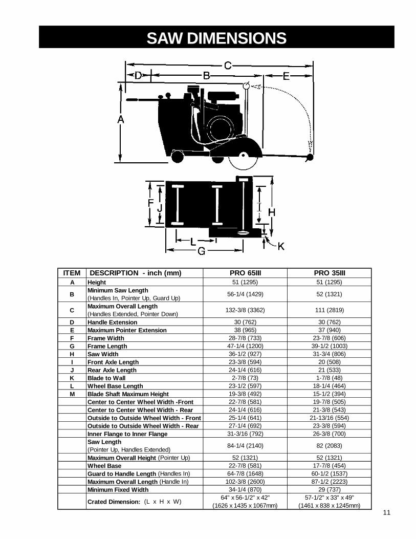
SAW DIMENSIONS
ITEM DESCRIPTION - inch (mm) PRO 65III PRO 35IIIA Height 51 (1295) 51 (1295)
B Minimum Saw Length(Handles In, Pointer Up, Guard Up) 56-1/4 (1429) 52 (1321)
C Maximum Overall Length(Handles Extended, Pointer Down) 132-3/8 (3362) 111 (2819)
D Handle Extension 30 (762) 30 (762)E Maximum Pointer Extension 38 (965) 37 (940)F Frame Width 28-7/8 (733) 23-7/8 (606)G Frame Length 47-1/4 (1200) 39-1/2 (1003)H Saw Width 36-1/2 (927) 31-3/4 (806)I Front Axle Length 23-3/8 (594) 20 (508)J Rear Axle Length 24-1/4 (616) 21 (533)K Blade to Wall 2-7/8 (73) 1-7/8 (48)L Wheel Base Length 23-1/2 (597) 18-1/4 (464)M Blade Shaft Maximum Height 19-3/8 (492) 15-1/2 (394) Center to Center Wheel Width -Front 22-7/8 (581) 19-7/8 (505) Center to Center Wheel Width - Rear 24-1/4 (616) 21-3/8 (543) Outside to Outside Wheel Width - Front 25-1/4 (641) 21-13/16 (554) Outside to Outside Wheel Width - Rear 27-1/4 (692) 23-3/8 (594)
Inner Flange to Inner Flange 31-3/16 (792) 26-3/8 (700)
Saw Length(Pointer Up, Handles Extended) 84-1/4 (2140) 82 (2083)
Maximum Overall Height (Pointer Up) 52 (1321) 52 (1321) Wheel Base 22-7/8 (581) 17-7/8 (454) Guard to Handle Length (Handles In) 64-7/8 (1648) 60-1/2 (1537) Maximum Overall Length (Handle In) 102-3/8 (2600) 87-1/2 (2223)
Minimum Fixed Width 34-1/4 (870) 29 (737)
Crated Dimension: (L x H x W) 64" x 56-1/2" x 42"(1626 x 1435 x 1067mm)
57-1/2" x 33" x 49"(1461 x 838 x 1245mm)

12
PRO 65 III DIESEL SPECIFICATIONS
Model No: 18S 26S 30S 36S 48W SCPL20GStandard Model: C50263 C50267 C50271 C50275 C50279 C50283
Standard w/Water Pump: C50264 C50268 C50272 C50276 C50280 C50284
STANDARD SAW FEATURESBlade Guard 18" 26" 30" 36" 48" 18" / 20"Capacity: (450mm) (650mm) (750mm) (900mm) (1200mm) (450mm /
508mm)Bladeshaft RPM: 2750 1900 1400 1400 1000 2750
Max. Depth Of Cut: 6-1/2" 10-1/2" 12" 15" 20" 1-3/4"(16.5cm) (26.7cm) (30.5cm) (38.1cm) (50.8cm) (4.5cm)
Arbor Size: 1" (25.4mm) with drive pin, blade can be mounted on either side of shaftBlade Shaft: 1-3/4" (44.5mm) diameter with quick disconnect flangesBlade Shaft Bearings: Dual self-aligning quad sealed bearingsBlade Shaft Drive: Jackshaft reduction systemBlade Control: Electro-hydraulic pump raises and lowers blade; positive depth stop, cutting depth indicator.
Quick-Lift blade raising and lowering button on the speed control lever.Blade Coolant: WaterAxles: Front 1-1/2" (38.1mm) diameter
Rear 1-1/4" (31.8mm) diameterWheels: Front 8" x 2-1/2" x 1" (203 x 63.5 x 25.4mm); Roller bearings, solid rubber tires, neoprene grease
seals, pressure lubrication fittings providedRear 10" x 3" (254 x 76mm) quick release; solid rubber tread
Transmission: Hydrostatic Transmission with sealed gearbox and single chain final drive, neutral safetystart switch and free wheeling neutral
Speed: Infinite speed 0 to 250 FPM forward and reverseChassis: Heavy-Duty, rigid, box and channel section constructionWeight - lb. (kg) Crated: 1,582 (712) 1,599 (720) 1,685 (758) 1,716 (772) 2,071 (932) 1,625 (731) Uncrated: 1,485 (668) 1,502 (676) 1,588 (715) 1,619 (729) 1,974 (888) 1,528 (688) Add for: Pump 10 (4.5) 10 (4.5) 10 (4.5) 10 (4.5) 10 (4.5) 10 (4.5)
Deluxe Spotlight 7 (3) 7 (3) 7 (3) 7 (3) 7 (3) 7 (3)

13
PRO 35 III DIESEL SPECIFICATIONSMODEL NO: 18S 26S 30SItem Number: C80231 C80233 C80235
Item No. C80232 C80234 C80236w/Water Pump:
STANDARD SAW FEATURESBlade Guard 18" 26" 30"Capacity: (450mm) (650mm) (750mm)
Bladeshaft RPM: 2500 1650 1650
Max. Depth Of Cut: 6-3/4" 10-3/4" 12-1/2"(17.15 cm) (27.31 cm) (31.8 cm)
Arbor Size: 1" (25.4mm) with drive pin, blade can be mounted on either side of shaftBlade Shaft: 1-7/16" (36.5mm) diameterBlade Shaft Bearings: Dual self-aligning pillow block ball bearingsBlade Shaft Drive: (2) 3 Groove 3VX banded beltsBlade Control: Electro-hydraulic pump raises and lowers blade; positive depth stop, cutting depth
indicator. Quick-Lift blade raising and lowering button on the speed control lever.Blade Coolant: Water; Zinc plated dual multiple-jet water spray tubes; Water supply connector located at
left rear of saw; Separate water control valves on each side of the saw.Axles: Front 1" (25.4mm) diameter
Rear 1" (25.4mm) diameterWheels: Front 6" x 2" x 1" (152 x 51 x 25.4mm); roller bearings, solid polyurethane tires, neoprene
grease seals, pressure lubrication fittings providedRear 8" x 2" x 1" (203 x 51 x 25.4mm); keyway; solid rubber tread; mounted and keyed on axle shaft
Transmission: Hydrostatic Transmission with sealed gearbox and single chain final drive, neutral safety startswitch, and free wheeling neutral
Speed Infinite speed 0 to 220 FPM forward and reverseChassis: Heavy-Duty, rigid, box and channel section construction
Weight - lb. (kg) Crated: 1,126 (510) 1,136 (515) 1,291 (578) Uncrated: 1,053 (477) 1,063 (482) 1,218 (548) Add for: Pump 10 (4.5) 10 (4.5) 10 (4.5)
Deluxe Spotlight 7 (3) 7 (3) 7 (3)

14
PRO 35 III 20HP ELECTRIC SPECIFICATIONSMODEL NO: 26S/230V 26S/460V 30S/230V 30S/460V 30S/575VItem Number: C80166 C80165 C80168 C80167 C80169Item No. N/A N/A N/A N/A N/Aw/Water Pump:
STANDARD SAW FEATURESBlade Guard Capacity: in (mm): 26" (650) 26" (650) 30" (750) 30" (750) 30" (750)Bladeshaft RPM: 1750 1750 1420 1420 1420Max. Depth Of Cut: 10-3/4" 10-3/4" 12-1/2" 12-1/2" 12-1/2"
(27.3 cm) (27.3 cm) (31.8 cm) (31.8 cm) (31.8 cm)Arbor Size: 1" (25.4mm) with drive pin, blade can be mounted on either side of shaft (two drive pins)Blade Shaft: 1-7/16" (36.5mm) diameterBlade Shaft Bearings: Dual self-aligning pillow block ball bearingsBlade Shaft Drive: Six(6) 3VX V-BeltsBlade Control: Electro-hydraulic pump raises and lowers blade; positive depth stop, cutting depth
indicator. Quick-Lift blade raising and lowering button on the speed control lever.Blade Coolant: Water; Zinc plated dual multiple-jet water spray tubes; Water supply connector located atleft rear of saw; Separate water control valves on each side of the saw.Axles: Front 1" (25.4mm) diameter
Rear 1" (25.4mm) diameterWheels: Front 6" x 2" x 1" (152 x 51 x 25.4mm); roller bearings, solid polyurethane tires, neoprene grease
seals, pressure lubrication fittings providedRear 8" x 2" x 1" (203 x 51 x 25.4mm); keyway; solid rubber tread; mounted and keyed on axleshaft
Transmission: Hydrostatic Transmission with sealed gearbox and single chain final drive, neutral andneutral safety start switch, parking brake, single control handle for neutral andforward/stop/reverse.
Speed Infinite speed 0 to 220 FPM forward and reverseBrake: Spring applied; Hydraulic pressure release; Caliper and Disc brakes.
Chassis: Heavy-Duty, rigid, box and channel section constructionWeight - lb. (kg) Crated: 933 (423) Uncrated: 860 (390) Add for: Pump 10 (4.5)
Deluxe Spotlight 7 (3)
15
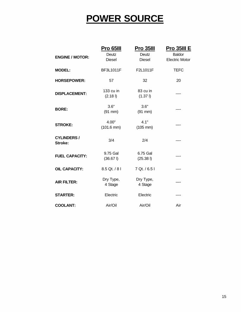
POWER SOURCE
Pro 65III Pro 35III Pro 35III EENGINE / MOTOR: Deutz
DieselDeutzDiesel
BaldorElectric Motor
MODEL: BF3L1011F F2L1011F TEFC
HORSEPOWER: 57 32 20
DISPLACEMENT: 133 cu in(2.18 l)
83 cu in(1.37 l) —-
BORE: 3.6"(91 mm)
3.6"(91 mm) —-
STROKE: 4.00"(101.6 mm)
4.1"(105 mm) —-
CYLINDERS /Stroke: 3/4 2/4 —-
FUEL CAPACITY: 9.75 Gal(36.67 l)
6.75 Gal(25.38 l) —-
OIL CAPACITY: 8.5 Qt. / 8 l 7 Qt. / 6.5 l —-
AIR FILTER: Dry Type,4 Stage
Dry Type,4 Stage —-
STARTER: Electric Electric —-
COOLANT: Air/Oil Air/Oil Air

16
SPECIAL INSTRUCTIONS FOR CHANGING BLADE SPEEDON CONCRETE / ASPHALT SAWS
WARNING: Do not exceed blade shaft speed shown for each blade size. Excessive bladespeed could result in blade breakage and serious personal injury.
NOTE: As shown on the chart, some blade guards accept more than one size blade.
RATEDRPM
PULLEYSIZE
RATEDRPM
PULLEYSIZE
14" 2560 4.12" 1760 6.00"18" 2560 4.12" 1760 6.00"26" 1760 4.12" 1760 4.12"30" 1430 4.12" 1760 3.35"
ELECTRIC MOTOR
PRO 35 III 20 HP ELECTRICMOTOR SPEED / BLADE SIZE
BLADE SHAFTBLADESIZE
LOADEDRPM
PULLEYSIZE
LOADEDRPM
PULLEYSIZE
MAXRPM
14" 2500 4.75" 2800 4.12" 295018" 2500 4.75" 2800 4.12" 295026" 1650 4.75" 2800 2.80" 295030" 1650 4.75" 2800 2.80" 2950
BLADE SHAFT ENGINE SPEEDBLADESIZE
PRO 35 III DIESELENGINE SPEED / BLADE SIZE
LOADEDRPM
PULLEYSIZE
LOADEDRPM
PULLEYSIZE
MAXRPM
14" 2750 4.12" 2800 8.0" 300018" 2750 4.12" 2800 8.0" 300026" 1900 4.12" 2800 5.6" 300030" 1400 5.60" 2800 5.6" 300036" 1400 5.60" 2800 5.6" 300048" 1000 7.60" 2800 5.6" 3000
PRO 65 III DIESELENGINE SPEED / BLADE SIZE
JACKSHAFT PULLEYS REMAIN THE SAME FOR ALL BLADE SIZES
BLADE SHAFT ENGINE SPEEDBLADESIZE

17

18
SAFETY FIRST!
WARNINGSDO’s AND DO NOT’s
WARNING: FAILURE TO COMPLY WITH THESE WARNINGS AND OPERATINGINSTRUCTIONS COULD RESULT IN DEATH OR SERIOUS BODILY INJURY.
DODO Read this entire operator’s manual before operating this machine. Understand all warnings, instructions, and controls.DO keep all guards in place and in good condition.DO wear safety approved hearing, eye, head and respiratory protection.DO read and understand all warnings and instructions on the machine.DO read and understand the symbol definitions contained in this manual.DO keep all parts of your body away from the blade and all other moving parts.DO know how to stop the machine quickly in case of emergency.DO shut off the engine and allow it to cool before refueling.DO turn the “ON/OFF” switch to the “OFF” position prior to connecting the machine to the power source.DO inspect the blade, flanges and shafts for damage before installing the blade.DO use the blade flange size shown for each blade size.DO use only reinforced abrasive blades or steel center diamond blades manufactured for use on concrete saws.DO use only the blade flanges supplied with the saw. Never use damaged or worn blade flanges.DO use only blades marked with a maximum operating speed greater than the blade shaft speed. Verify speed by checking blade
shaft rpm and pulley diameters and blade flange diameters.DO verify saw drive configuration by checking blade shaft RPM, pulley diameters, and blade flange diameter.DO read all safety materials and instructions that accompany any blade used with this machine.DO inspect each blade carefully before using it. If there are any signs of damage or unusual wear, DO NOT USE THE BLADE.DO mount the blade solidly and firmly, Wrench tighten the arbor nut.DO make sure the blade and flanges are clean and free of dirt and debris before mounting the blade on the saw.DO use the correct blade for the type of work being done. Check with blade manufacturer if you do not know if blade is correct.DO use caution and follow the instructions when loading and unloading the machine.DO operate this machine only in well ventilated areas.DO instruct bystanders on where to stand while the machine is in operation.DO establish a training program for all operators of this machine.DO clear the work area of unnecessary people. Never allow anyone to stand in front of or behind the blade while the engine is
running.DO make sure the blade is not contacting anything before starting the engine.DO use caution when lifting and transporting this machine.DO always tie down the machine when transporting.DO use caution and follow instructions when setting up or transporting the machine.DO have all service performed by competent service personnelDO make sure electric powered machines are plugged into a properly grounded circuitDO make sure power cords are the proper size and in good condition.DO verify the blade arbor hole matches the machine spindle before mounting the blade.DO always check for buried electrical cables before sawing. If unsure, contact the local utilities.DO move the machine at least 10 feet (3 meters) from the fueling point before starting the engine and make sure the gas cap on the
machine and the fuel can is properly tightened.DO lift only from the lift bail.DO clean the machine after each day’s use.DO follow all electrical codes in your area.DO use correct voltage and proper extension cords. Never carry tool by cord or yank it to disconnect it from receptacle. Keep cord
away from heat, oil and sharp edges.DO disconnect tools from power source when not in use, before servicing and when changing accessories.DO carefully maintain and clean for better and safer performance. Follow instructions for changing accessories. Inspect tool cords
periodically and, if damaged, have repaired by authorized service facility.DO use the proper blade flange size for each blade size. Never use damaged or worn blade flanges.DO use caution when handling fuel.DO only cut in a straight line.DO only saw as deep as the job specifications require.DO always give a copy of this manual to the equipment user. If you need extra copies, call TOLL FREE 1-800-288-5040.

19
SAFETY FIRST!
WARNINGSDO’s AND DO NOT’s
WARNING: FAILURE TO COMPLY WITH THESE WARNINGS AND OPERATINGINSTRUCTIONS COULD RESULT IN DEATH OR SERIOUS BODILY INJURY.
DO NOT
*****************
This saw was designed for certain applications only. DO NOT modify this saw or use for any application otherthan for which is it was designed. If you have any questions relative to its application, DO NOT use the saw untilyou have written Diamant Boart, Inc. and we have advised you.
Diamant Boart, Inc.17400 West 119th Street
Olathe, Kansas 66061
DO NOT operate this machine unless you have read and understood this operator’s manual.DO NOT operate this machine without the blade guard, or other protective guards in place.DO NOT stand behind or in front of the blade path while the engine is running.DO NOT leave this machine unattended while the engine is running.DO NOT work on this machine while the engine is running.DO NOT operate this machine when you are tired or fatigued.DO NOT use a wet blade without adequate water supply to the blade.DO NOT exceed maximum blade speed shown for each blade size. Excessive speed could result in blade breakage.DO NOT operate the machine if you are uncertain of how to run the machine.DO NOT use damaged equipment or blades.DO NOT touch or try to stop a moving blade with your hand.DO NOT cock, jam, wedge or twist the blade in a cut.DO NOT transport a cutting machine with the blade mounted on the machine.DO NOT use a blade that has been dropped or damagedDO NOT use carbide tipped blades.DO NOT touch a dry cutting diamond blade immediately after use. These blades require several minutes to cool after each cut.DO NOT use damaged or worn blade flanges.DO NOT allow other persons to be near the machine when starting, refueling, or when the machine is in operation.DO NOT operate this machine in an enclosed area unless it is properly vented.DO NOT operate this machine in the vicinity of anything that is flammable. Sparks could cause a fire or an explosion.DO NOT allow blade exposure from the guard to be more than 180 degrees.DO NOT operate this machine with the belt guard or blade guard removed.DO NOT operate this machine unless you are specifically trained to do so.DO NOT use a blade that has been over heated (Core has a bluish color).DO NOT jam material into the blade.DO NOT grind on the side of the blade.DO NOT lay power cords in or near the water.DO NOT tow this machine behind a vehicle.DO NOT leave the machine unattended with the motor running.DO NOT replace the motor with any motor that does not have a special grounding connectionDO NOT use the tie down brackets for lifting this machine.DO NOT operate this machine with the transmission guard removed.DO NOT cut deeper than 1" per pass with a dry blade. Step cut to achieve deeper cuts.DO NOT operate this machine while using drugs or alcohol.

20
1A. KNOB: Use to tighten operator grip handles.
1B. HANDLE BARS: For operator gripping.
1C. FUEL TANK FILL: Fill the fuel tank at thislocation.
1D. OIL PRESSURE GAUGE: Shows the engine oilpressure
1E. WATER SAFETY SWITCH: Stops the engine ifthe water supply to the blade is interrupted.
1F. VOLTAGE GAUGE: Shows the voltage of theelectrical system.
1G. FUEL GAUGE: Shows the level of fuel in the fueltank.
1H. ENGINE TACHOMETER: Shows the engineRPM’s.
1J. BLADE DEPTH STOP: Sets the depth stop forrepetitive cuts at the same depth.
1K. BLADE DEPTH INDICATOR: Displays cuttingdepth.
1L. ENGINE START SWITCH: Start the engineusing this switch.
1M. WATER PUMP SWITCH: Optional
1N. PARKING BRAKE (Optional): Pull up to lock rearaxle parking brake. Push down to release Parkingbrake.
1O. WATER INLET:
1P. ENGINE THROTTLE:
1R. RAISE/LOWER SWITCH: Located on speedcontrol lever. Use to raise and lower the saw.Push up to raise saw upward. Push down to lowerthe saw.
1S. SPEED CONTROL LEVER: Controls forwardand reverse directions, stop, and the speed of thesaw.
1T. RED PALM SWITCH: For EMERGENCY STOPof the saw. Stops all systems except lights, pull upto reset. Do not use for routine stopping.
1U. WATER OUTLET:
1V. STOP POSITION: The saw will stop travelmovement when the speed control lever (1S) is inthis position. The engine will not start unless theSpeed Control Lever (1S) is in the STOP position.
1W. TRANSMISSION ENGAGE NEUTRAL KNOB:Pull up to disengage transmission and push thesaw in freewheel wheel mode. Push down toengage transmission and drive under power.
1Z. WATER VALVE:
FIG. 1
(PRO 65 III DIESEL SHOWN)

21
2A. BLADE SHAFT BOLT OR NUT: Use to tightenthe outer flange against the diamond blade.
2B. OUTER FLANGE: Use to hold the diamondblade in position.
2C. OUTER FLANGE ARBOR: Use to support thediamond blade.
2D. LOCKING PIN: Use to prevent the diamondblade from rotating on the shaft during operation.
2E. DIAMOND BLADE: Use as the cutting tool forconcrete and asphalt surfaces.
2F. INNER FLANGE: Inside support used to holdthe diamond blade in position.
2G. BLADE GUARD NOSE LATCH: Use to latchthe front of the blade guard in the down position.
2H. BLADE GUARD FRONT: The front section ofthe blade guard.
2I. BLADE SHAFT: Supports the blade flanges andblade.
3A. WATER VALVE: Use to control the water supplyto the diamond blade.
3B. LIFTING BAIL: The saw can be lifted from thispoint.
3C. FRONT GUIDE: Use to locate the path of thediamond blade on the cutting line.
3D. REAR GUIDE: Use to locate the path of thediamond blade on the cutting line.
FIG. 3
3C
3B3A
3D
FIG. 2PRO 35 IIIPRO 65 III

22
4A. JACKSHAFT CLAMPING BOLTS: LocksJackshaft in position.
4B. BUMPER LOCKING BOLTS: Locks IdlerBumper in place.
4C. BUMPER: Reduces vibration on Idler ArmAssembly.
4D. COGGED FLAT DRIVE BELT: Drives jackshaftfrom engine crankshaft.
4E. JACKBOLT: Turn counterclockwise to tensionv-belts.
4F. V-BELTS: Banded 3 Groove 3VX set of 3.Drives Bladeshaft.
4G. JACKSHAFT ASSEMBLY: Transfers power andslows RPM to bladeshaft.
4H. IDLER ARM: Arm holds idler pulley in position.
4I. SPROCKET BOLTS: Holds Jackshaft Sprocketin place.
4J. JACKSHAFT SPROCKET: Drives jackshaft.
4K. ENGINE CRANKSHAFT SPROCKET: Drivescogged belt.
4L. IDLER PULLEY: Applies force to backside ofcogged drive belt to maintain tension.
4M. BLADESHAFT: Supports Blade flanges andBlade.
4N. IDLER SPRING: Maintains tension on idlerpulley.
4O. SPRING ANCHOR: Anchors spring, can berotated to install spring.
4P. STRAIGHT EDGE TOOL: Used to align enginesprocket and crankshaft sprocket.
4Q. BLADESHAFT BOLTS: Fastens bladeshaft andjackshaft. Right side is adjustable to alignjackshaft.
4R. V-BELT PULLEY: On Bladeshaft..
4S. TENSION GAUGE: Goodyear TensionRite™gauge indicates proper tension when installingv-belts.
FIG. 4 (PRO 65 III Diesel Only)

23
SERVICE DAILY:1. Check engine oil level.2. Check blade guard for damage.3. Check hoses and clamps for damage
or looseness. Tighten or replace as necessary.4. Check air cleaner restriction indicator. Replace
primary air filter if indicator is red.5. Lubricate bladeshaft bearings (Standard ball
bearings only - Pro 35).6. Lubricate front wheel bearings.
SERVICE EVERY 50 HOURS:1. Clean engine air fins.2. Lubricate rear axle bearings.3. Check blade drive V-belt tension.
DO NOT over tension!!!
SERVICE EVERY 100 HOURS:1. Replace engine oil and filter.2. Lubricate front axle pivot bearings.3. Check wheels for wear or damage.4. Check transmission drive chain and sprockets for
looseness.5. Check engine air cleaner hose and clamps.6. Check DC lift pump fluid level.7. Check hydrostatic transmission fluid level.
SERVICE EVERY 250 HOURS:1. Lubricate bladeshaft bearings. (Quad-sealed
bearings - Pro 65).2. Replace fuel filter (in-line type).
SERVICE EVERY 500 HOURS:1. Replace DC lift pump fluid.2. Replace hydrostatic transmission fluid.3. Replace fuel filter (spin-on type).
SERVICE YEARLY:1. Replace air filter safety element.
PRE OPERATION CHECKLIST
Before leaving our factory, every machine is thoroughly tested. Follow our instructions strictly andyour machine will give you long service in normal operating conditions.
Before starting up the machine, make sure you read this entire Operation’s Manual and are familiarwith the operation of the machine.
WITH MACHINE COLD AND SETTING LEVEL:
1. Check engine oil. Fill to the full mark on dip stick with 15W40 class CE or CD oil.2. Connect battery cables.3. Electric Models: Verify all electrical connections are intact.
1 - 2 HOUR OPERATION CHECK LIST:
ALWAYS park machine on a level surface with the engine “OFF” and the ignition switch set in the“OFF” position before performing any maintenance. Let the machine cool down!!
1. Check the engine air cleaner hose clamps. Tighten as required.2. Tension the blade drive V-belts. DO NOT over tension!!3. Check the transmission drive chain. DO NOT over tighten!!
SCHEDULED MAINTENANCE QUICK REFERENCE
Before performing any maintenance, ALWAYS park the machine on a level surface with the engine“OFF” and the ignition switch set in the “OFF position.

24
MANDA-TORY
INDICATIONINFORMATIONINSTRUCTION
WARNING PROHIBITION
Before starting up the machine, make sure youread this entire manual and are familiar withthe operation of this machine.
The working area must be completely clear,well lit and all safety hazards removed.
The operator must wearprotective clothingappropriate to the work heis doing.
MODEL 12" 14" 18" 20" 24"35 III Diesel 3½ 4 ½ 6 ½ 7 ½ 9½65 III Diesel 3 ½ 4 ½ 6 ½ 7 ½ 9 ½Side Plunge --- --- 2" 3" n/a
Blade Size
MODEL 26" 30" 36" 42" 48"35 III Diesel 10 ½ 12 ½ n/a n/a n/a65 III Diesel 10 ½ 12 15 17 20Side Plunge n/a n/a n/a n/a n/a
Blade Size
Any persons not involved in the workshould leave the area.
Use only blades marked with a maximumoperating speed greater than the blade shaftspeed.
(See Fig. 1 and 2)
Set The Handles To The Desired Length:• Loosen Knob (1A), pull the Handle Bar (1B) in or out to
desired length, then tighten the Knob (1A).
Moving The Saw With The Engine Off:• Turn Engine Start Switch (1L) to the “1” (RUN) position.• Raise the saw by pressing up on the Toggle Switch
(1R) on the Speed Control Lever (1S) until theDiamond Blade (2E) (if installed) clears the pavementsurface.
• Release the Parking Brake (if equipped) by pulling upon Brake Knob (1N).
• Pull up on the Neutral Knob (1W).• The saw can now be moved by standing behind it and
pushing [while holding the Handle Bars (1B)].
DO NOT attempt to push the saw while it isparked on a grade (or hill). The saw operatorcould lose control of the saw and causeinjury to himself or other person(s) in the area.
Moving The Saw With Engine On:• Turn Engine Start Switch (1L) to the “1” (RUN) position.• Raise the saw by pressing up on the Toggle Switch
(1R) on Speed Control Lever (1S) untilDiamond Blade (2E) (if installed) clears the pavementsurface.
• Push down on the Neutral Knob (1W).• Push down on the Parking Brake Knob (1N)
(if equipped).• Set Water Safety Switch (1E) to “0” (OFF).• Speed Control Lever (1S) must be in the STOP (1V)
position to start the saw. The engine WILL NOT startunless the Speed Control Lever (1S) is in theSTOP (1V) position.
• Diesel Models: Pull Throttle (1P) out halfway.• Turn the Engine Start Switch (1L) to the “2” (START)
position until the engine starts, then release the switch.It will return to “1” (RUN) position. If the engine doesnot start, repeat these steps.
• PUSH the Control Lever (1S) forward for Forward sawmovement, or to the rear for Reverse saw movement.The further you push the lever the faster the speed.
2 MOVING THE MACHINEThese signs will giveadvice for your safety
Before leaving our factory every machine isthoroughly tested.
Follow our instructions strictly and your machine willgive you long service in normal operating conditions.
Use: Wet sawing of old and new concrete and asphalt.
Tools: Diamond blades — water cooled, Ø: 12",14", 18",20", 24", 26", 30", 36", 42" and 48" with Arbor Ø - 1"(For information, contact your Target supplier)
Depths of Cut (Maximum):
1 USE

25
(See Fig. 1, 2, and 3)
Turn engine off. Set Speed Control Lever(1S) to STOP position. Remove diamondblade (2E) before transport. Set NeutralControl Knob (1W) to ENGAGE position(DOWN). Set Parking Brake (1N) ON (UP)(if equipped).
When moving the saw up and down ramps, with theengine on, use extreme caution.• To go DOWN a ramp, drive the saw FORWARD slowly.• To go UP a ramp, back the saw in REVERSE slowly.
WARNING! DO NOT roll the saw down aramp while the transmission is inNEUTRAL (1V).
Lifting The Saw. The saw can only be lifted bythe factory installed Lifting Bail (3B).
To Transport By Vehicle:• Set Engine Start Switch (1L) in the “0” (OFF) position.• Set Speed Control Lever (1S) in the STOP (1V) position.• Set Transmission Engage (1W) to engage down
position.• Set Parking Brake (1N) to up position (if equipped).• Push Handle Bars (1B) inward and tighten Knobs (1A).
Block the saw in place and secure it intoplace with chains or straps to preventmovement during transport.
4 CHECK BEFORE STARTING
Take into account the working conditions fromthe health and safety point of view.
• Fuel: Check the engine maintenance manual.∗ Diesel Models: #2 Diesel fuel is recommended.
• Check that the engine oil level is correct. Because theengine often operates at an angle, check the oil level(with engine horizontal) frequently to ensure that theoil level never falls below the lower mark on thedipstick. 15W40 oil is recommended.
• For start up, refer to the engine manual.
5 FITTING THE BLADE
(See Fig. 1 and 2)
Always set the Engine Start Switch (1L) tothe “0” (OFF) position before mounting theblade.
• Set the Engine Start Switch (1L) to the “0” (OFF)position.
• Raise the machine to a high position [by pressing theToggle Switch (1R) on the Control Lever (1S) upward].
• Loosen the bolt on the Blade Guard Latch (2G).• Raise the front half of the Blade Guard (2H).• Unscrew the Blade Shaft Bolt (2A) or Nut (2A). Re-
move Outer Flange (2B).• Fit Diamond Blade (2E) to Outer Flange Arbor (2C) or
Shaft Arbor (2I).• Install Outer Flange (2B) into the Blade Shaft (2I) mak-
ing sure that the Locking Pin (2D) passes through theDiamond Blade (2E) and into the Inner Flange (2F).
Note the direction of rotation of the blade.The direction of rotation is shown by anarrow on both the Diamond Blade (2E) andthe Blade Guard (2H). Make sure that thecontact surfaces on the Diamond Blade (2E),Inner & Outer Flanges (2B & 2F) and BladeArbor (2C) are clean.
• Rotate Outer Flange (2B) and Diamond Blade (2E) inthe opposite direction of blade rotation to removebacklash.
• Install and tighten Blade Shaft Bolt (2A) or Nut (2A)using the Blade Shaft Wrench while firmly holding theDiamond Blade (2E).
• Lower front half of Blade Guard (2H) and tighten theBolt (2G) on the Blade Guard Latch (2G).
The Blade Shaft Bolt (2A) or Nut (2A) on theRight Hand side has Left Hand threads. TheBlade Shaft Bolt (2A) or Nut (2A) on the LeftHand side has Right Hand threads.
Slip on blade guards are provided with a safetylatch which engages the support spade and abolt to retain the rear of the guard.
Do not operate this saw without the latchengaged and the bolt installed. Inspect bladeguards and latches frequently. DO NOT USEIF DAMAGED.
3 TRANSPORT (BLADE REMOVED)

26
• Move the saw forward or reverse slowly by pushing orpulling on the Speed Control Lever (1S). Move thesaw slowly to prevent stalling the blade. Make sure theFront Guide (3C), Rear Guide (3D) and theDiamond Blade (2E) stay on the line.
• Lower the saw by pushing the Toggle Switch (1R) downon the Speed Control Lever (1S) until the DiamondBlade (2E) is at the desired cutting depth (See “BladeCutting Depth Information—Below).
Blade Cutting Depth Information:This saw is equipped with a Blade Depth Indicator (1K)which indicates the depth at which the Diamond Blade(2E) is cutting. This saw also includes a Blade DepthStop (1J) which stops the cutting depth of the blade at aspecified depth.
Use of the Blade Depth Indicator (1K):• If the engine is running - Turn the Engine Start Switch
(1L) to the “0” (OFF) position to STOP the engine.• Turn the Engine Start Switch (1L) to the “1” (ON)
position.• Lower the Diamond Blade (2E) by pushing the Toggle
Switch (1R) on the Control Lever (1S) downward untilthe Diamond Blade (2E) touches the surface to be cut.
• Rotate the Blade Depth Indicator Knob (1K) to the zeroposition. The blade cutting depth will now be indicatedon the Depth Indicator (1K) when the blade is loweredinto the cutting surface.
Use of the Blade Depth Stop (1J):• Lower the blade by pushing the Toggle Switch (1R) on
the Speed Control Lever (1S) downward until theDiamond Blade (2E) is at the required depth [asindicated on the Blade Depth Indicator (1K)].
• Set the Blade Depth Stop (1J) by turning the knobclockwise until tight. Now the maximum cutting depthis set. If the saw is raised out of the cut surface forany reason it can now be lowered to this specifieddepth by lowering the blade into the cutting surfacewith the Toggle Switch (1R) on the Control Lever (1S).
The saw WILL NOT lower to any depth greaterthan the position set on the BLADE DEPTHSTOP (1J). Therefore, if a deeper cut isrequired, the Depth Stop Knob MUST beloosened, then SET to the new depthrequired.
To Remove A SLIP-ON GUARD:• Using a Wrench, remove the rear retaining bolt.• Raise the Spade Safety Latch to unlatch and lift guard
off spade.
To Install A SLIP-ON GUARD:• Lower guard onto spade until latch engages.• Install bolt in rear of guard and tighten using Wrench.
(See Fig. 1, 2 and 3)
Always pay extreme care and attention to thepreparation of the machine before starting.
Remove all wrenches and tools from the floorand the machine.
Always keep blade guard and transmissionguard in place.
• Follow the operating instructions and warnings on topof the saw cowl.
• Close the Water Valve (1Z).• Mark the surface to be cut by drawing a line where the
cut is to be made.• Pull out Handle Bars (1B) to desired length and tighten
Knobs (1A).• Lower the Front Guide (3C). Align the Front Guide
(3C), Rear Guide (3D) and Diamond Blade (2E) withthe line on the surface.
• To start the saw with no water pressure, set the WaterSafety Switch (1O) to the “0” (OFF) position.
• Set Speed Control Lever (1S) to the STOP (1V)position. Saw will not start unless the Speed ControlLever (1S) is in the STOP (1V) position.
• Start the engine using the Engine Start Switch (1L).Follow the procedure in the engine manual.
• Let the engine warm up for several minutes with theEngine Throttle (1P) set at idle.
• When ready, open the Water Valve (1Z).• Set Water Safety Switch to “1” (ON).
Test for adequate water supply [2-1/2 to5 gal/min (10 to 20 lit./min)]. Low water flowwill cause damage to diamond blades.
6 STARTING THE SAW

27
8 INCIDENTS DURING SAWING
(See Fig. 1 and 2)
If ENGINE STOPS during sawing, check the following:• Engine out of fuel—Check Fuel Gauge (1G).• Lack of water signals the Water Safety Switch (1E) to
stop the engine. Press button (1E) to “0” (OFF), andthen restart the engine.
• Excessively fast cutting speed will stall engine.• Red Palm Emergency Switch (1T) has been pressed
down. Reset by pulling up the red button.• Engine may be hot or cogged belt may be broken.
If DIAMOND BLADE (2E) STOPS during sawing, check:• Drive belt tension is inadequate.
SAW LOWERS TOO FAST:• The lowering rate of the saw can be adjusted using the
Flow Control Valve at the rear or the saw. If the sawfalls too quickly, turn the knob on the Flow Control ValveCLOCKWISE until an adequate lowering rate is set.
If the ENGINE or BLADE STALLS for any reason, raisethe blade completely from the cut, inspect the machinethoroughly before restarting the engine. When loweringthe blade into a partial cut, align the blade exactly with thecut to prevent damage to the blade.
Before performing any maintenance,ALWAYS park the machine on a levelsurface with the Engine OFF and the EngineStart Switch in the “0” (OFF) position.
After each use: CLEAN the machine.
LUBRICATION:
ENGINE OIL: Check daily. Change Engine Oil and OilFilter after every 100 HOURS of operation. 15W40 isgenerally recommended.∗ Diesel Models: 15W40 CE or CD
Pro 35 III Pro 65 IIICapacity: 7.0 Qt. (6.5l) 8.5 Qt. (8l)
STANDARD BALL BEARING BLADESHAFTBEARINGS: Lubricate daily with a Premium Lithium 12based grease conforming to NLG1 GRADE #2consistency. (Pro 65, Pro 35)Lubricate Daily:• Front Wheel Bearings• Blade Shaft Bearings (Pro 35 III only)
Lubricate every 50 hours:• Rear Axle Bearings
9 ADJUSTMENTS: STRAIGHT LINE SAWING
While cutting, the saw may steer to the right from therequired straight line marked on the cutting surface (if theDiamond Blade (2E) is installed on the right hand side). Ifthis occurs, the Rear Axle of the saw can be pivoted tocompensate for this situation.• Loosen the three (3) 1/2"-13 UNC Bearing Mounting
Bolts on the Left End of the rear axle.• The axle is adjusted by turning the M12 Adjustment Bolt
located at the rear lower left of saw cowl.• If the saw steers to the RIGHT while sawing, Turn the
Adjustment Bolt COUNTER-CLOCKWISE.• If the saw steers to the LEFT while sawing, Turn the
Adjustment Bolt CLOCKWISE.• Verify transmission belts and pulleys and chain and
sprockets are in line.• Re-tighten the three (3) 1/2"-13 UNC Bearing
Mounting Bolts.
(See Fig. 1, 2 and 3)
For EMERGENCY STOP, press down the REDPALM SWITCH (1T) on the cowl. This willstop the engine, disconnect power to allelectrical items except lights. Reset the REDPALM SWITCH (1T) by pulling up the red but-ton. Then restart engine.
DO NOT use the EMERGENCY STOP SWITCH(1T) for normal, routine engine stopping.
• Move The Control Lever (1S) to the STOP (1V)position.
• Raise the Diamond Blade (2E) out of the cut bypressing the Toggle Switch (1R) on the Control Lever(1S) upward until the Diamond Blade (2E) clears thesurface.
• Set the Engine Throttle (1P) to the IDLE position.• Turn off the Water Valve (3A).• Allow engine to run for 5 minutes to cool the
Turbocharger, or damage to Turbocharger will occur.• STOP the engine by turning the Engine Start Switch
(1L) to the “0” (OFF) position.
DO NOT turn Key Switch (1l) off while saw ismoving.
7 STOPPING THE SAW
10 MAINTENANCE
Entrust all repairs to your authorized dealeronly.
28
Lubricate every 100 hours:• Front Axle Pivot Bearings
Lubricate Every 250 Hours: (Pro 65 only)• Quad-Sealed Blade Shaft Bearings: Use only a
Premium Lithium 12 based grease conforming to NLG1GRADE #2 consistency.
TRANSMISSION GEARBOX:• This unit is lubricated for the life of the unit, so no
lubrication is required. If, for any reason, the unitdoes need to be refilled, use Mobilux EP023,1.5 quarts (1.41 l), synthetic gear lubricant.
HYDRAULIC SYSTEM:• Refer to Section 12, Hydraulic System .
AIR FILTER:• Replace the Air Filter Outer Element when the
Restriction Indicator Red Signal appears. DO NOTclean the Inner Safety Element!!!!!
To Change The Air Filter Element:• Remove the Air Filter end cap by unlatching the clamps,
and pulling the cap off.• Pull the Air Filter Outer Element out of the filter housing
and replace. DO NOT clean the filter element by tap-ping it on the ground or other objects, this will damagethe filter element!
• Install Air Filter Outer Element by pushing it into thehousing. Replace end cap and close latches.
• Replace the Inner Safety Element once per year or ifit becomes damaged.
• Replace any damaged filters or gaskets.• Check air hose and clamps for damage or looseness.
Tighten or replace as required.
DRIVE CHAIN AND SPROCKETS:• Check for wear and looseness. Tighten as required.
Do not over tighten the Drive Chain!! Thecorrect tightness allows for some slack.
Store in a safe place out of reach of children.Remove all adjustment tools and wrenches.Store diamond tool in a safe place so itcannot be damaged.
FUEL FILTERS:• Replace in-line Fuel Filter every 250 hours.• Replace spin-on Fuel Filter every 500 hours.
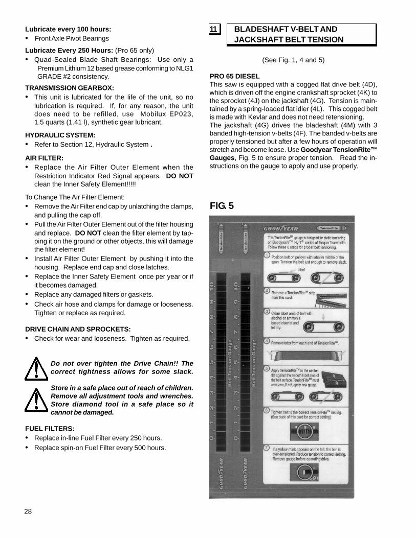
(See Fig. 1, 4 and 5)
PRO 65 DIESELThis saw is equipped with a cogged flat drive belt (4D),which is driven off the engine crankshaft sprocket (4K) tothe sprocket (4J) on the jackshaft (4G). Tension is main-tained by a spring-loaded flat idler (4L). This cogged beltis made with Kevlar and does not need retensioning.The jackshaft (4G) drives the bladeshaft (4M) with 3banded high-tension v-belts (4F). The banded v-belts areproperly tensioned but after a few hours of operation willstretch and become loose. Use Goodyear TensionRite™Gauges, Fig. 5 to ensure proper tension. Read the in-structions on the gauge to apply and use properly.
11 BLADESHAFT V-BELT ANDJACKSHAFT BELT TENSION
FIG. 5

29
• Using a Wrench, Rotate jackbolt (4E) COUNTER-CLOCKWISE to just take up the slack in the Belts.
• Apply TensionRite™ Adhesive Strip (4S) to all threebelts in the center of the span as indicated on theinstructions.
• Using a Wrench, Rotate jackbolt (4E) COUNTER-CLOCKWISE until the Yellow indicator line on theTensionRite™ strip lines up with the appropriatenumber for new belts
Pro 65 III Diesel Tension # 3.5
Do not over tension. Save Extra TensionRite™gauges for future retensioning.
• Tighten (2) Clamp bolts (4A) locking the Jackshaft tube(4G) in place.
• Install Sprocket (4J), on to jackshaft.• Install 4 Bolts (4I) and lock-washers on the Jackshaft
Sprocket (4J). Tighten with wrench.• Install Flat Cogged Belt (4D) over both sprockets (4J,
4K). It may be necessary to remove the idler spring(4N) from the spring anchor (4O) to get the belt on.
• The spring anchor (4O) can be loosened and rotatedto make installing the Idler Spring (4N) easier. Installthe spring and tighten bolts.
• Press the Idler Bumper (4C) down against the IdlerArm (4H) slightly compressing the rubber.
• Tighten bolts (4B) to lock the Bumper (4C) in place.• Replace Frame Corner and Belt Guard.
SPROCKET ALIGNMENT - PRO 65 DIESEL:
The sprockets, (4K, 4J) are aligned at the factory. If forany reason the jackshaft (4G) or bladeshaft (4M) areremoved or replaced, it is critical to maintain alignment.Use a straight edge (4P) to align both sprockets within,0.03 inches. The right bladeshaft bolts (4Q) can be loos-ened to adjust the jackshaft (4G) to get the sprockets (4K,4J) parallel. The sprocket (4J) can be adjusted left orright to align with the engine sprocket (4K). Align the v-belt pulley on the bladeshaft (4M) to the v-belt pulley onthe jackshaft (4R) after the sprockets have been aligned.
TO TENSION V-BELTS - PRO 65 DIESEL:
• Turn Engine Start Switch (1L) to the “0” (OFF)position.
• Remove Belt Guard.• Use Wrench to loosen clamping bolts (4A).• Loosen Bolts (4B) on the Bumper (4C) to release
tension on Cogged Belt (4D).• Banded V-Belts supplied by Target come with a
Goodyear TensionRite™ tension gauge (4S). Whenretensioning belts, ALWAYS use TensionRite™ gaugeto ensure achieving the proper tension.
• Using a Wrench, Rotate jackbolt (4E) CLOCKWISE torelease the tension.
• Apply TensionRite™ Adhesive Strip (4S) to all threebelts in the center of the span as indicated on the in-structions.
• Using a Wrench, Rotate jackbolt (4E) COUNTER-CLOCKWISE until the Yellow indicator line on theTensionRite™ Strip lines up with the appropriatenumber for used belts.
Pro 65 III Diesel Tension # 2.6
• Do not over tension.• Tighten (2) Clamp bolts (4A) locking the Jackshaft tube
(4G) in place.• Press the Idler Bumper (4C) down against the Idler
Arm (4H) slightly compressing the rubber.• Tight bolts (4B) to lock the Bumper (4C) in place.
TO INSTALL NEW V-BELT - PRO 65 DIESEL:
• Turn Engine Start Switch (1L) to the “0” (OFF)position.
• Remove Belt Guard.• Remove Frame Corner.• Loosen Bolts (4B) on the Bumper (4C) to release
tension on Cogged Belt (4D).• Remove Cogged Belt (4D).• Remove 4 Bolts (4I) on the Jackshaft Sprocket (4I).• Remove Sprocket (4J).• Use Wrench to loosen clamping bolts (4A).• Using a Wrench, Rotate jackbolt (4E) CLOCKWISE.
This will rotate the Jackshaft tube (4G) down, loosen-ing the V-Belts (4F).
• Banded V-Belts supplied by Target come with aGoodyear TensionRite™ tension gauge (4S). Whenreplacing belts, ALWAYS use the TensionRite™ gaugeto ensure achieving the proper tension.
• Replace Banded V-belts (4F) in complete sets only!

30
14 IMPORTANT ADVICE(See Fig. 2)
• Tighten loose nuts and bolts regularly, particularlyafter several hours of operation.
• Check V-Belt tension regularly. Re-tightenV-Belts as necessary. Replace V-Belts in completesets only.
• Remove the Diamond Blade (2E) for storage. Store itcarefully.
• Check the water spray over the Diamond Blade (2E)periodically.
• Tighten the Diamond Blade (2E) firmly on the BladeArbor (2C).
• Make sure the contact faces of Flanges (2B & 2F),Diamond Blade (2E), and Blade Shaft (2I) are clean.
• Use the Emergency Stop Switch (1T) ONLY in the caseof emergency. Do not use for normal engine stopping.
• Put the saw in STOP (1V) before turning the key to theOFF position.
If installed, this saw has a mechanical parking brake thatlocks the rear axle by engaging a mechanical lock into agear on the rear axle.
• To engage parking brake, pull up on the parking brakeknob (1N). The brake will lock when the locking leverlines up with a slot in the gear.
• To disengage the brake, push down on the parkingbrake knob (1N) .
13 PARKING BRAKE (OPTIONAL)
The hydraulic system on this saw is used to RAISE /LOWER the Diamond Blade (2E) and to propel the sawFORWARD or REVERSE. The hydraulic system consistsof a Hydrostatic Transmission, a DC Lift Pump with a FlowControl Valve, and a Hydraulic Lift Cylinder.
• Check Hydrostatic Transmission fluid level periodically.Maintain oil level with SAE 10W30 API CLASSSE,CC,CD motor oil. DO NOT OVERFILL! Check oillevel when saw is level.
• Change Hydrostatic Transmission fluid every 500 hoursof operation. Fill Hydraulic Reservoir with SAE 10W30API Class SE,CC,CD motor oil. DO NOT OVERFILL!Check oil level when saw is level.
• Check the DC Lift Pump fluid level periodically.Maintain oil level with Dextron III transmission fluid. DONOT OVERFILL!
• The lowering rate of the saw can be adjusted using theFlow Control Valve at the rear of the saw. If the sawfalls too quickly, turn the knob on the Flow Control ValveCLOCKWISE until an adequate lowering rate is set.
12 HYDRAULIC SYSTEM
TO TENSION V-BELTS -PRO 35 III DIESEL AND ELECTRIC:
ALWAYS use Goodyear TensionRite™ Gauges, Fig. 5 toensure achieving the proper tension. Refer to the instruc-tions on the back of the TensionRite gauge for proper use.This saw is equipped with high tension banded V-belts.The belts are properly tensioned at the factory but after afew hours of operation they will stretch and become loose.
Model Used Belts New BeltsPro 35 III Diesel 26”/30” # 1.75 # 2.25Pro 35 III Diesel 18” # 2.25 # 3.0Pro 35 III Electric # 2.25 # 3.0
• Turn Engine Start Switch (1L) to the “0” (OFF)position.
• Using the wrench, loosen the horizontal clamping boltsat the front of the machine.
• Turn the Tensioning Bolt [at the front of machine]CLOCKWISE until the V-Belts are tight.
• Replace V-Belts in complete sets only.
Never tension V-Belts beyond the originalfactory tension. Loose V-Belts result in poorsaw performance and short belt life.
The Pro 35III is available in several 20HP electricversions. It is available in 4 different voltages with three(3) different motors. It comes completely wired withappropriate plugs, connectors, wiring, motor starter,overload heaters and an in dash current load meter. Theelectric saw is operated exactly like a gas saw after it isconnected to the power source. The key must be turnedto the Start position and will engage the motor starter.Turn the key off, the motor will stop. The emergency stopswitch and water safety switch will also stop the motor.
Operate the electric saw at a speed where the currentload meter does not exceed 100% of full load current.Exceeding 100% of the full load amperage will result inthe current overload heaters to overheat and shut off theelectric motor. After allowing the overload to cool off,(approx. 5 minutes), press the RESET button on the frontof the electrical enclosure box. Turn the key to the startposition to engage the motor starter.
15 PRO 35III ELECTRIC SAWS

31
16 ACCESSORIESBLADE GUARD CONVERSION KITS:Use the proper size blade guard for the particulardiamond blade size being operated. Consult factory forblade guards that are available.
WEIGHT KIT: (Pro 65 III)A rear mounted Weight Kit is available. It is standardequipment for units shipped with 48" blade guards. It canbe purchased as an accessory for units with smaller bladeguard sizes.
WARNINGS!!!
DO turn the “ON/OFF” switch to the “0” (OFF)position prior to connecting the machine to thepower source.
DO make sure electric powered machines are pluggedinto a properly grounded circuit.
DO make sure power cords are the proper size andin good condition.
DO follow all electrical codes in your area.DO use correct voltage and proper extension cords.
Never carry tool by cord or yank it to disconnectit from receptacle. Keep cord away from heat, oiland sharp edges.
DO disconnect tools from power source when not inuse, before servicing and when changingaccessories.
DO carefully maintain and clean for better and saferperformance. Follow instructions for changingaccessories. Inspect tool cords periodically and,if damaged, have repaired by authorized servicefacility.
DO NOT lay power cords in or near the water.DO NOT leave this machine unattended with the motor
running.DO NOT replace the motor with any motor that does not
have a special grounding connection.
Item Part No. 35III 65IIIDeluxe Light Kit 167656 181117Tie Down Kit 167190 X X48" Conversion Kit 191345 XBlade Guards:
18" Slip-on 176635 X X18" Bolt-on 174273 X X26" Slip-on 176645 X X26" Bolt-on 167475 X X30" Slip-on 166911 X X30" Bolt-on 167676 X X36" Slip-on 166931 X36" Bolt-on 174275 X48" Bolt-on 166932 X
Water Pump Kit 167554 191322Blade Stack Kit(Std. Shaft) (4.50") 176292 XBlade Stack Kit,QDS Flanges: 5.00" Dia 6.00" Dia
177327163480
XX
Side Plunge Kit 191349 X
ACCESSORIES AND KITS
Notes:1. If A Box Is NOT CHECKED, That Item Is NOT AVAILABLE For
The Saw Model Shown.2. New Saw Models (Pro 35 III, Pro 65 III) Have Some OF These Items
Installed As Standard.
Equipment: Check Specification Sheet For Standard Features.
32
The instructions for use and spare parts found in thisdocument are for information only and are not binding.As part of our product quality improvement policy, wereserve the right to make any and all technical modifi-
cations without prior notice.
The manufacturer accepts noresponsibility caused by unsuitable
use or modifications
These saws are equipped with the majority of itshardware items (capscrews, nuts, etc.) utilizing theMETRIC system, although a limited number of hardwareitems continue to use the ENGLISH (INCH) system of mea-surement. Within this manual and the corresponding partslist, these components are specified by themeasurement. Be sure to use the proper hardware(METRIC or ENGLISH) or threaded fasteners (such aswelded-on nuts) could be damaged.
17 METRIC HARDWARE 18 REPAIRS
We carry out all repairs in the shortest possible time andat the most economical prices. (See front page for ouraddress and phone numbers)
For quick supply of spare parts and to avoid any lost time,it is essential to quote the data on the manufacturer’s platefixed to the machine and the part number (s) to bereplaced with every order.
19 SPARE PARTS

33
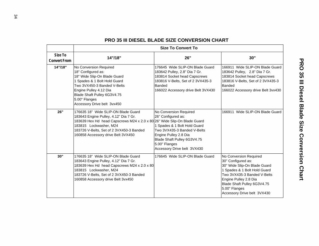
34
PRO
35 III Diesel B
lade Size Conversion C
hart
30"
166911 Wide SLIP-ON Blade Guard183642 Pulley, 2.8” Dia 7 Gr.183814 Socket head Capscrews183816 V-Belts, Set of 2 3VX435-3 Banded166022 Accessory drive Belt 3vx430
166911 Wide SLIP-ON Blade Guard
No Conversion Required30" Configured as:30" Wide Slip-On Blade Guard1 Spades & 1 Bolt Hold GuardTwo 3VX435-3 Banded V-BeltsEngine Pulley 2.8 Dia Blade Shaft Pulley 6G3V4.755.00" FlangesAccessory Drive belt 3VX430
26"
176645 Wide SLIP-ON Blade Guard183642 Pulley, 2.8” Dia 7 Gr.183814 Socket head Capscrews183816 V-Belts, Set of 2 3VX435-3 Banded166022 Accessory drive Belt 3VX430
No Conversion Required26" Configured as:26" Wide Slip-On Blade Guard1 Spades & 1 Bolt Hold GuardTwo 3VX435-3 Banded V-BeltsEngine Pulley 2.8 Dia Blade Shaft Pulley 6G3V4.755.00" FlangesAccessory Drive belt 3VX430
176645 Wide SLIP-ON Blade Guard
14"/18"
No Conversion Required18" Configured as:18" Wide Slip-On Blade Guard1 Spades & 1 Bolt Hold GuardTwo 3VX450-3 Banded V-BeltsEngine Pulley 4.12 Dia Blade Shaft Pulley 6G3V4.755.00" FlangesAccessory Drive belt 3vx450
176635 18” Wide SLIP-ON Blade Guard183643 Engine Pulley, 4.12” Dia 7 Gr.183639 Hex Hd head Capscrews M24 x 2.0 x 80183815 Lockwasher, M24183726 V-Belts, Set of 2 3VX450-3 Banded160858 Accessory drive Belt 3VX450
176635 18” Wide SLIP-ON Blade Guard183643 Engine Pulley, 4.12” Dia 7 Gr.183639 Hex Hd head Capscrews M24 x 2.0 x 80183815 Lockwasher, M24183726 V-Belts, Set of 2 3VX450-3 Banded160858 Accessory drive Belt 3vx450
Size ToConvert From
14"/18"
26"
30"
PRO 35 III DIESEL BLADE SIZE CONVERSION CHARTSize To Convert To
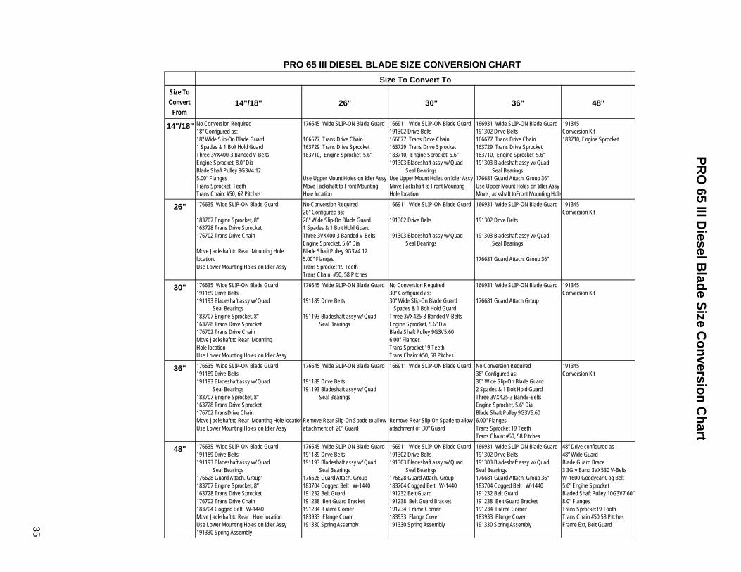
35
PRO
65 III Diesel B
lade Size Conversion C
hart
48"
36"
30"
26"
14"/18"
Size ToConvert
From
176635 Wide SLIP-ON Blade Guard191189 Drive Belts191193 Bladeshaft assy w/ Quad Seal Bearings176628 Guard Attach. Group"183707 Engine Sprocket, 8”163728 Trans Drive Sprocket176702 Trans Drive Chain183704 Cogged Belt W-1440 Move Jackshaft to Rear Hole locationUse Lower Mounting Holes on Idler Assy191330 Spring Assembly
176635 Wide SLIP-ON Blade Guard191189 Drive Belts191193 Bladeshaft assy w/ Quad Seal Bearings183707 Engine Sprocket, 8”163728 Trans Drive Sprocket176702 TransDrive Chain Move Jackshaft to Rear Mounting Hole locationUse Lower Mounting Holes on Idler Assy
176635 Wide SLIP-ON Blade Guard191189 Drive Belts191193 Bladeshaft assy w/ Quad Seal Bearings183707 Engine Sprocket, 8”163728 Trans Drive Sprocket176702 Trans Drive Chain Move Jackshaft to Rear MountingHole locationUse Lower Mounting Holes on Idler Assy
176635 Wide SLIP-ON Blade Guard
183707 Engine Sprocket, 8”163728 Trans Drive Sprocket176702 Trans Drive Chain
Move Jackshaft to Rear Mounting Holelocation.Use Lower Mounting Holes on Idler Assy
No Conversion Required18" Configured as:18" Wide Slip-On Blade Guard1 Spades & 1 Bolt Hold GuardThree 3VX400-3 Banded V-BeltsEngine Sprocket, 8.0” Dia Blade Shaft Pulley 9G3V4.125.00" FlangesTrans Sprocket TeethTrans Chain: #50, 62 Pitches
14"/18"
176645 Wide SLIP-ON Blade Guard191189 Drive Belts191193 Bladeshaft assy w/ Quad Seal Bearings176628 Guard Attach. Group 183704 Cogged Belt W-1440191232 Belt Guard191238 Belt Guard Bracket191234 Frame Corner183933 Flange Cover191330 Spring Assembly
176645 Wide SLIP-ON Blade Guard
191189 Drive Belts191193 Bladeshaft assy w/ Quad Seal Bearings
Remove Rear Slip-On Spade to allowattachment of 26” Guard
176645 Wide SLIP-ON Blade Guard
191189 Drive Belts
191193 Bladeshaft assy w/ Quad Seal Bearings
No Conversion Required26" Configured as:26" Wide Slip-On Blade Guard1 Spades & 1 Bolt Hold GuardThree 3VX400-3 Banded V-BeltsEngine Sprocket, 5.6” Dia Blade Shaft Pulley 9G3V4.125.00" FlangesTrans Sprocket 19 TeethTrans Chain: #50, 58 Pitches
176645 Wide SLIP-ON Blade Guard
166677 Trans Drive Chain163729 Trans Drive Sprocket183710, Engine Sprocket 5.6”
Use Upper Mount Holes on Idler AssyMove Jackshaft to Front MountingHole location
26"
166911 Wide SLIP-ON Blade Guard191302 Drive Belts191303 Bladeshaft assy w/ Quad Seal Bearings176628 Guard Attach. Group 183704 Cogged Belt W-1440191232 Belt Guard191238 Belt Guard Bracket191234 Frame Corner183933 Flange Cover191330 Spring Assembly
166911 Wide SLIP-ON Blade Guard
Remove Rear Slip-On Spade to allowattachment of 30” Guard
No Conversion Required30" Configured as:30" Wide Slip-On Blade Guard1 Spades & 1 Bolt Hold GuardThree 3VX425-3 Banded V-BeltsEngine Sprocket, 5.6” Dia Blade Shaft Pulley 9G3V5.606.00" FlangesTrans Sprocket 19 TeethTrans Chain: #50, 58 Pitches
166911 Wide SLIP-ON Blade Guard
191302 Drive Belts
191303 Bladeshaft assy w/ Quad Seal Bearings
166911 Wide SLIP-ON Blade Guard191302 Drive Belts166677 Trans Drive Chain163729 Trans Drive Sprocket183710, Engine Sprocket 5.6”191303 Bladeshaft assy w/ Quad Seal Bearings Use Upper Mount Holes on Idler AssyMove Jackshaft to Front MountingHole location
30"
166931 Wide SLIP-ON Blade Guard191302 Drive Belts191303 Bladeshaft assy w/ QuadSeal Bearings176681 Guard Attach. Group 36"183704 Cogged Belt W-1440191232 Belt Guard191238 Belt Guard Bracket191234 Frame Corner183933 Flange Cover191330 Spring Assembly
No Conversion Required36" Configured as:36" Wide Slip-On Blade Guard2 Spades & 1 Bolt Hold GuardThree 3VX425-3 BandV-BeltsEngine Sprocket, 5.6” Dia Blade Shaft Pulley 9G3V5.606.00" FlangesTrans Sprocket 19 TeethTrans Chain: #50, 58 Pitches
166931 Wide SLIP-ON Blade Guard
176681 Guard Attach Group
166931 Wide SLIP-ON Blade Guard
191302 Drive Belts
191303 Bladeshaft assy w/ Quad Seal Bearings
176681 Guard Attach. Group 36"
166931 Wide SLIP-ON Blade Guard191302 Drive Belts166677 Trans Drive Chain163729 Trans Drive Sprocket183710, Engine Sprocket 5.6”191303 Bladeshaft assy w/ Quad Seal Bearings176681 Guard Attach. Group 36" Use Upper Mount Holes on Idler AssyMove Jackshaft toFront Mounting Hole
36"
48” Drive configured as :48” Wide GuardBlade Guard Brace3 3Grv Band 3VX530 V-BeltsW-1600 Goodyear Cog Belt5.6” Engine SprocketBladed Shaft Pulley 10G3V7.60”8.0” FlangesTrans Sprocke:19 ToothTrans Chain #50 58 PitchesFrame Ext, Belt Guard
191345Conversion Kit
191345Conversion Kit
191345Conversion Kit
191345Conversion Kit183710, Engine Sprocket
48"
Size To Convert To
PRO 65 III DIESEL BLADE SIZE CONVERSION CHART

36
Diagram 1 - Wiring Diagram - PRO 35 III Diesel, 182127

37
Diagram 1 - Wiring Diagram - PRO 35 III Diesel, 182127Parts List
DIAG.LOC.
PARTNO. DESCRIPTION QTY.
REQ.1 -- WIRING HARNESS, ENGINE (DEUTZ 4271805) 12 182126 WIRE HARNESS, PRO III DIESEL 13 163179 CABLE, BATTERY, NEGATIVE 14 163180 CABLE, BATTERY, POSITIVE 15 139261 CABLE, BATTERY, POSITIVE, HYD. 16 176714 CABLE, BATTERY, NEGATIVE, HYD. 17 -- STARTER (DEUTZ 1180995) 18 176398 SWITCH, NEUTRAL SAFETY 19 166711 SWITCH, ROCKER 2
10 -- ALTERNATOR, (DEUTZ 1180648) 111 166622 BLOCK, FUSE 112 166708 RELAY, N.O. N.C. 313 166121 SOLENOID RELAY 114 178724 SWITCH, WATER PRESSURE 115 183896 GAUGE, BATTERY VOLTS 116 183853 GAUGE, OIL PRESSURE 117 182137 GAUGE, TACH/HOUR METER 118 166707 SWITCH, IGNITION 119 182100 HANDLE, TRANSMISSION/LIFT CONTROL 120 163121 BATTERY, 12 VOLT 121 166350 PUMP, HYDRAULIC, LIFT ASSY 122 178645 CIRCUIT BREAKER, 30 AMP 123 176383 E. STOP SWITCH 124 166594 COIL - 12V DC 125 164977 WATER PUMP 126 191026 SENDER/SWITCH, OIL PRESSURE (DEUTZ 1175981) 127 -- SENDER/SWITCH, OIL TEMPERATURE (DEUTZ 1179305) 128 -- SOLENOID, FUEL (DEUTZ 4270581) 129 -- B+ WIRE (DEUTZ 4179133) 1

38
Diagram 2 - Wiring Diagram - PRO 65 III Diesel, 182139

39
DIAG.LOC.
PARTNO. DESCRIPTION QTY.
REQ.1 -- WIRING HARNESS, ENGINE (DEUTZ 4270531) 12 182126 WIRE HARNESS, PRO III DIESEL 13 163179 CABLE, BATTERY, NEGATIVE 14 163180 CABLE, BATTERY, POSITIVE 15 139261 CABLE, BATTERY, POSITIVE, HYD. 16 176714 CABLE, BATTERY, NEGATIVE, HYD. 17 -- STARTER (DEUTZ 1181751) 18 176398 SWITCH, NEUTRAL SAFETY 19 166711 SWITCH, ROCKER 2
10 -- ALTERNATOR, (DEUTZ 1180648) 111 166622 BLOCK, FUSE 112 166708 RELAY, N.O. N.C. 313 166121 SOLENOID RELAY 114 178724 SWITCH, WATER PRESSURE 115 183896 GAUGE, BATTERY VOLTS 116 183853 GAUGE, OIL PRESSURE 117 182138 GAUGE, TACH/HOUR METER 118 166707 SWITCH, IGNITION 119 182100 HANDLE, TRANSMISSION/LIFT CONTROL 120 163121 BATTERY, 12 VOLT 121 166350 PUMP, HYDRAULIC, LIFT ASSY 122 178645 CIRCUIT BREAKER, 30 AMP 123 176383 E. STOP SWITCH 124 166594 COIL - 12V DC 125 164977 WATER PUMP 126 191026 SENDER/SWITCH, OIL PRESSURE (DEUTZ 1175981) 127 -- SENDER/SWITCH, OIL TEMPERATURE (DEUTZ 1179305) 128 -- SOLENOID, FUEL (DEUTZ 4270581) 129 -- B+ WIRE (DEUTZ 4179132) 1
Diagram 2 - Wiring Diagram - PRO 65 III Diesel, 182139Parts List

40
Diagram 3 - Ladder Diagram - PRO 35 III Diesel and PRO 65 III Diesel, 182121

41
Diagram 3 - Ladder Diagram - PRO 35 III Diesel and PRO 65 III Diesel, 182121Component Designators
DESIGNATOR DEVICE FUNCTIONALT ALTERNATOR BATTERY CHARGINGCB CIRCUIT BREAKER MAIN POWER
CR1 CONTROL RELAY POWER TO FUSE BLOCKCR2 CONTROL RELAY ENGINE STARTERCR3 CONTROL RELAY ENGINE TEMP SHUTDOWNF1 FUSE, 5A ALTERNATOR EXCITATIONF2 FUSE, 5A ENGINE GAUGESF3 FUSE, 10A FUEL SOLENOID CIRCUITF4 FUSE, 5A RAISE-LOWER CIRCUITF5 FUSE, 10A WATER PUMP (OPTIONAL)F6 FUSE, 10A LIGHT KIT (OPTIONAL)
GA1 GAUGE ENGINE TACHOMETER & HOURMETERGA2 GAUGE ENGINE OIL PRESSUREGA3 GAUGE BATTERY VOLTMETERM1 MOTOR ENGINE STARTERM2 MOTOR HYDRAULIC PUMPM3 MOTOR WATER PUMP (OPTIONAL)P1 PLUG CONNECTOR COWL TO ENGINE HARNESS
SV1 SOLENOID VALVE RAISE-LOWER SAWSW1 SWITCH (KEY) ENGINE, OFF-RUN-STARTSW2 SWITCH (PUSH-PULL) EMERGENCY STOPSW3 SWITCH (ROCKER) WATER SWITCH OFFSW4 SWITCH (ROCKER) LIFT SWITCH, RAISE-OFF-LOWERSW5 SWITCH (ROCKER) WATER PUMP, ON-OFF (OPTIONAL)

42
Diagram 4 - Wiring Diagram - PRO 35 III Electric, 182062

43
Diagram 4 - Wiring Diagram - PRO 35 III Electric, 182602Parts List
DIAG.LOC.
PARTNO. DESCRIPTION QTY.
REQ.1 176913 CABLE, CONTROL 12 182061 WIRING HARNESS, COWL 13 176914 TRANSFORMER, CURRENT 14 176915 STARTER, MOTOR CONTROL 15 176917 OVERLOAD RELAY 16 176838 CABLE, BATTERY, POSITIVE, HYD. 17 176714 CABLE, BATTERY, NEGATIVE, HYD. 18 176398 SWITCH, NEUTRAL SAFETY 19 166711 SWITCH, ROCKER 2
10 117154 ALTERNATOR 111 166622 BLOCK, FUSE 112 166708 RELAY, N.O. N.C. 213 166121 SOLENOID RELAY 114 178724 WATER PRESSURE SWITCH 115 166438 GAUGE, BATTERY VOLTS 116 176918 METER, MOTOR LOAD 117 163779 GAUGE, HOUR METER 118 166707 SWITCH, IGNITION 119 182100 HANDLE,TRANSMISSION/LIFT CONTROL 120 183433 CORD, 4 GA, 208/230 VOLT/20 HP (208/230V/20HP Only) 120 183402 CORD, 8 GA, 460/575 VOLT/20 HP, 575 VOLT/30 HP (460/575V/20HP & 575V/30HP Only) 120 176957 CORD, 6 GA, 460 VOLT/30 HP (460V/30HP Only) 121 163121 BATTERY, 12 VOLT 122 166633 HYDRAULIC PUMP ASSY 123 176383 E. STOP SWITCH 124 166594 COIL - 12V DC 125 164977 WATER PUMP, ASSY 126 178645 CIRCUIT BREAKER, 30 AMP 127 176949 OVERLOAD HEATER, 208 VOLT/20 HP (208V/20HP Only) 327 176948 OVERLOAD HEATER, 230 VOLT/20 HP (230V/20HP Only) 327 176947 OVERLOAD HEATER, 460 VOLT/20 HP (460V/20HP Only) 327 176946 OVERLOAD HEATER, 575 VOLT/20 HP (575V/20HP Only) 327 183361 OVERLOAD HEATER, 460 VOLT/30 HP (460V/30HP Only) 327 183337 OVERLOAD HEATER, 575 VOLT/30 HP (575V/30HP Only) 328 176931 CONNECTOR, 208/230 VOLT/20 HP (208/230V/20HP Only) 128 176942 CONNECTOR, 480 VOLT/20 HP (480V/20HP Only) 128 176944 CONNECTOR, 575 VOLT/20 & 30 HP (575V/20&30HP Only) 128 183403 CONNECTOR, 480 VOLT/30 HP (480V/30HP Only) 129 176930 PLUG, 208/230 VOLT/20 HP (208/230V/20HP Only) 129 176943 PLUG, 480 VOLT/20 HP (480V/20HP Only) 129 176945 PLUG, 575 VOLT/20 & 30 HP (575V/20&30HP Only) 129 183404 PLUG, 480 VOLT/30 HP (480V/30HP Only) 1

44
This equipment includes the electric Motor, Motor overload protection, and Motor control circuit. For correct operation,the equipment must be selected and configured for each voltage and horsepower rating as shown in the following table.Inspection and/or changes to the equipment are to be performed only after the electrical service has been discon-nected and then by qualified personnel.
Current Transformer Wiring
A single primary turn is made with a single pass of the redwire through the hole in the transformer, entering from the‘H1’ side. Two primary turns are made by passing the redwire through the transformer hole twice, resulting in a singleloop. The -2 secondary turns are made by passing thewhite wire of the transformer through the hole two timesfrom opposite the ‘H1’ side. The +6 secondary turns aremade by passing the white wire of the transformer throughthe hole six times entering from the ‘H1” side.
NOTICE
The end user is responsible for providing the electrical service in accordance with the National Electrical Codeand any other applicable local codes. Service must include at the minimum: Motor disconnecting means,Motor branch-circuit short-circuit protection, Motor branch-circuit ground-fault protection, and correctlysized Motor circuit conductors.
208V, 3 Ph 230V, 3 Ph 460V, 3 Ph 575V, 3 Ph 460V, 3 Ph 575V, 3 PhDBI Drive Motor PN 167042 001325 001325 161461 183360 183335Rated Horsepower 20 20 20 20 30 30Motor Full Load Current 60 A 52 A 26 A 20.6 A 37 A 29.6 AMotor Connections
DBI Overload Heater PN 176949 176948 176947 176946 183361 183337 Vendor PN SFH83 SFH82 SFH75 SFH72 SFH78 SFH76Power Cord PN 183433 183433 183402 183402 176957 183402 Cord Description 4 Cond, 4 GA 4 Cond, 4 GA 4 Cond, 8 GA 4 Cond, 8 GA 4 Cond, 6 GA 4 Cond, 8 GADBI Power Connector PN 176931 176931 176942 176944 183403 176944 Vendor PN 460C9W 460C9W 2733SW 2743SW 460C7W 2743SWDBI Power Plug PN 176930 176930 176943 176945 183404 176945 Vendor PN 460P9W 460P9W 2731SW 2741SW 460P7W 2741SWCurrent Transformer wiring * No of primary turns 1 1 2 2 1 2 No of secondary turns -2 0 0 +6 +5 -4
H1 Side White wire to Load MeterBlack wire to Load Meter
Red wire to motor starter
Diagram 5 - PRO 35 III Electric Wiring Instructions

45
Diagram 6 - Ladder Diagram - PRO 35 III Electric, 182068

46
Target Corporate OfficeCustomer Service ……….……………. 800-288-5040Corp. Office...………………………..... 913-928-1000Cust. Service FAX …………………… 800-825-0028Corp. Office FAX ..………………….... 913-438-7951Cust. Service, Int’l. …………………… 913-928-1300Int’l. E-mail ......…………….…. [email protected]
Target Latin America, Mexico, Caribbean,Central and South America17400 West 119th StreetOlathe, Kansas 66061Phone ……………………………….…. 913-928-1255FAX ………………………………….…. 913-438-7938E-mail ……………………………. [email protected]
Target Canada17400 West 119th StreetOlathe, Kansas 66061Customer Service …………….…….... 800-288-5040E-mail …………………………… [email protected]
Target Hong Kong, ChinaDiamant Boart Pte Ltd.Unit E, 13/F., Infotech Centre,21 Hung To Road, Kwun Tong,Hong KongPhone ……………………..…………. 852-2516-6602FAX ………………………..…………. 852-2516-6605E-mail …………………….... targethk.netvigator.com
Target Japan, Korea, Taiwan1803-36 Oyama-MachiMachida-Shi, Tokyo 194-0212JapanPhone ………………………………… 8142-797-0212FAX …………………………………… 8142-798-7515E-mail ………………… [email protected]
Target Australia, New Zealand/Dembicon Pty. Ltd29 Kinkaid AvenueNorth Plympton, Adelaide SA 5037AustraliaPhone ………………….…………..…... 61-83751000FAX …………………….………….…… 61-83710990E-mail ……………….. [email protected] ……………….……. www.dembicon.com.au
Target BrazilPix Do BrasilRua José de Oliveira CoutinhoSão Paulo, Brazil CEP 01144-020Phone ………………………………. 55 11 3611-8383FAX ………………………….……... 55 11 3619-3022E-mail …………………………. [email protected]
Target Singapore, Thailand, Vietnam,Malaysia, IndonesiaPhone ………………………………….. 65-9628-6175FAX ……………………………………… 65-234-2896e-mail …………………………. [email protected]
European HeadquartersDB Construction Business GroupAvenue Du Pont De Luttre, 741190 Brussels, BelgiumPhone ……………………………….. (32-2) 348-3669FAX ………………………………….. (32-2) 348-3136Internet …………………….. www.diamant-boart.com
Target Internet …………….. www.targetblue.com