OM, 650 RTT, 96093000201, 2006-12, Tiller - hsqGlobal · 2 • Keep children and pets away. † Do...
28
650RTT Owner's Manual
Transcript of OM, 650 RTT, 96093000201, 2006-12, Tiller - hsqGlobal · 2 • Keep children and pets away. † Do...

650RTTOwner's Manual

2
• Keep children and pets away.• Do not overload the machine capacity by attempting
to till too deep at too fast a rate.• Never operate the machine at high speeds on slippery
surfaces. Look behind and use care when backing.• Never allow bystanders near the unit.• Use only attachments and accessories approved by
the manufacturer of the tiller.• Never operate the tiller without good visibility or light.• Be careful when tilling in hard ground. The tines may
catch in the ground and propel the tiller forward. If this occurs, let go of the handlebars and do not restrain the machine.
MAINTENANCE AND STORAGE• Keep machine, attachments, and accessories in safe
work ing condition.• Check shear pins, engine mounting bolts, and other
bolts at frequent intervals for proper tightness to be sure the equip ment is in safe working condition.
• Never store the machine with fuel in the fuel tank inside a building where ignition sources are present, such as hot water and space heaters, clothes dryers, and the like. Allow the engine to cool before storing in any enclosure.
• Always refer to the operator’s guide instructions for im por tant details if the tiller is to be stored for an ex-tended period.
- IMPORTANT -CAUTIONS, IMPORTANTS, AND NOTES ARE A MEANS OF ATTRACTING ATTENTION TO IMPORTANT OR CRIT I CAL IN FOR MA TION IN THIS MANUAL.
IMPORTANT: USED TO ALERT YOU THAT THERE IS A POS SI BIL I TY OF DAM AG ING THIS EQUIP MENT.
NOTE: Gives essential information that will aid you to bet-ter understand, incorporate, or execute a particular set of instructions.
Look for this symbol to point out im- por tant safety precautions. It meansCAUTION!!! BE COME ALERT!!! YOUR SAFE TY IS INVOLVED.
CAUTION: Always disconnect spark plug wire and place wire where it can- not contact spark plug in order to pre- vent ac ci den tal starting when setting up, trans port ing, adjusting or making re pairs.
SAFETY RULESSafe Operation Practices for Walk-Behind Powered Ro ta ry Tillers
TRAINING• Read the Owner’s Manual care ful ly. Be thor ough ly
fa mil iar with the controls and the proper use of the equip ment. Know how to stop the unit and disengage the controls quickly.
• Never allow children to operate the equipment. Never allow adults to op er ate the equipment without proper instruction.
• Keep the area of operation clear of all persons, par- tic u lar ly small children, and pets.
PREPARATION• Thoroughly inspect the area where the equipment is
to be used and remove all foreign objects.• Disengage all clutches and shift into neutral before
starting the engine (mo tor).• Do not operate the equipment with out wearing ad e -
quate outer gar ments. Wear footwear that will im prove footing on slippery surfaces.
• Handle fuel with care; it is highly fl ammable. • Use an approved fuel container. • Never add fuel to a running engine or hot engine. • Fill fuel tank outdoors with extreme care. Never fi ll fuel
tank indoors.• Replace gasoline cap securely and clean up spilled
fuel before restarting.• Use extension cords and receptacles as specifi ed by
the manufacturer for all units with electric drive motors or electric starting motors.
• Never attempt to make any adjustments while the engine (motor) is running (except where specifi cally rec om mend ed by manufacturer).
OPERATION • Do not put hands or feet near or under rotating parts.• Exercise extreme caution when op er at ing on or cross-
ing gravel drives, walks, or roads. Stay alert for hidden hazards or traffi c. Do not carry pas sen gers.
• After striking a foreign object, stop the engine (motor), remove the wire from the spark plug, thoroughly in spect the tiller for any damage, and repair the damage before restarting and op er at ing the tiller.
• Exercise caution to avoid slipping or falling.• If the unit should start to vibrate ab nor mal ly, stop the
engine (motor) and check immediately for the cause. Vi bra tion is generally a warning of trouble.
• Stop the engine (motor) when leaving the operating position.
• Take all possible precautions when leav ing the ma chine unattended. Disengage the tines, shift into neutral, and stop the engine.
• Before cleaning, repairing, or inspecting, shut off the engine and make certain all moving parts have stopped. Disconnect the spark plug wire, and keep the wire away from the plug to prevent accidental starting. Disconnect the cord on electric motors.
• Do not run the engine indoors; exhaust fumes are dangerous.
• Never operate the tiller without proper guards, plates, or other safety protective devices in place.
WARNINGThe engine exhaust from this product con- tains chem i cals known to the State of Cal i -for nia to cause cancer, birth defects, or other reproductive harm.

3
CONGRATULATIONS on your purchase of a new tiller. It has been designed, en gi neered and manu fac tured to give you the best pos sible de penda bil ity and per form ance.
Should you experience any prob lems you can not easily remedy, please contact your nearest authorized service center. We have com pe tent, well-trained tech ni cians and the proper tools to service or repair this unit.
Please read and retain this manual. The in struc tions will enable you to assemble and main tain your tiller prop erly. Always observe the “SAFETY RULES”.
CUSTOMER RESPONSIBILITIES• Read and observe the safety rules.• Follow a regular schedule in maintaining, caring for
and using your tiller.• Follow instructions under “Maintenance” and “Stor age”
sections of this Owner’s Manual.
IMPORTANT: THIS UNIT IS EQUIPPED WITH AN INTERNAL COMBUSTION ENGINE AND SHOULD NOT BE USED ON OR NEAR ANY UNIMPROVED FOREST-COVERED, BRUSH-COVERED OR GRASS COVERED LAND UNLESS THE ENGINE'S EXHAUST SYSTEM IS EQUIPPED WITH A SPARK ARRESTER MEETING APPLICABLE LOCAL LAWS (IF ANY). IF A SPARK ARRESTER IS USED, IT SHOULD BE MAINTAINED IN EFFECTIVE WORK ING ORDER BY THE OPERATOR.
IN THE STATE OF CALIFORNIA, A SPARK ARRESTER IS REQUIRED BY LAW (SECTION 4442 OF THE CALIFORNIA PUBLIC RESOURCES CODE). OTHER STATES MAY HAVE SIMILAR LAWS. FEDERAL LAWS APPLY ON FEDERAL LANDS. SEE YOUR AUTHORIZED SERVICE CENTER/DEPARTMENT FOR SPARK ARRESTER.
MAINTENANCE ...................................................11-13SERVICE & ADJUSTMENTS ...............................14-17STORAGE..................................................................18TROUBLESHOOTING...............................................19REPAIR PARTS-TILLER ......................................20-26
TABLE OF CONTENTS
SAFETY RULES ..........................................................2CUSTOMER RESPONSIBILITIES...............................3PRODUCT SPECIFICATIONS.....................................3ASSEMBLY...............................................................4-6OPERATION ...........................................................7-10MAINTENANCE SCHEDULE ....................................11
Gasoline Capacity: 3 Quarts Unleaded Reg u lar
OIL (API-SG-SL): SAE 30 (Above 40°F) (Capacity 20 oz./0.6L) SAE 5W-30/10W30 (Below 40°F)
Spark Plug: Champion (Gap: .030"/0.76mm) RC12YC
PRODUCT SPECIFICATIONS

4
TOOLS REQUIRED FOR ASSEMBLYA socket wrench set will make assembly easier. Standard wrench sizes are listed.
(1) Utility knife
(1) Tire pressure gauge
(1) Pair of pliers
(1) 9/16" wrench
OPERATOR’S POSITION (See Fig. 1)When right or left hand is mentioned in this manual, it means when you are in the operating position (standing behind tiller handles).
Your new tiller has been assembled at the factory with exception of those parts left unassembled for shipping purposes. To ensure safe and proper operation of your tiller all parts and hardware you assemble must be tightened securely. Use the correct tools as necessary to insure proper tightness.
FRONT
OPERATOR’SPOSITION
LEFT RIGHT
FIG. 1
(1) Hairpin Clip
(1) Carriage Bolt 3/8-16 UNC x 1 Grade 5
(1) Center Locknut 3/8-16 UNC
(1) Handle Lock Lever(1) Flat Washer 13/32 x 1 x 11 Gauge
CONTENTS OF HARDWARE PACK
(2) Handle Locks
(1) Pivot Bolt 3/8-16 UNC Grade 5 Extra Shear Pins & Clips
ASSEMBLY

5
carton_3
handles_10
ASSEMBLY• Grasp handle assembly. Hold in “up” position. Be sure
handle lock remains in gearcase notch. Slide handle assembly into position.
HANDLE ASSEMBLY"UP" POSITION
FIG. 4
UNPACKING CARTON (See Fig. 2)
CAUTION: Be careful of exposed sta ples when handling or disposing of cartoning material.
IMPORTANT: WHEN UN PACK ING AND AS SEM BLING TILLER, BE CAREFUL NOT TO STRETCH OR KINK CABLES.• While holding handle assembly, cut cable ties se cur ing
handle assembly to top frame and depth stake. Let handle assembly rest on tiller.
• Remove top frame of carton.• Slowly ease handle assembly up and place on top of
carton.• Cut down right hand front and right hand rear cor ners
of carton, lay side carton wall down.• Remove packing material from handle assembly.
FIG. 2
SHIFT ROD
INSTALL HANDLE (See Figs. 3, 4, and 5)• Insert one handle lock (with teeth facing outward) in
gearcase notch. (Apply grease on smooth side of handle lock to aid in keeping lock in place until handle assembly is lowered into position.)
HANDLEAS SEM BLY
FIG. 3
HANDLE ASSEMBLY
GEARCASENOTCH
HANDLELOCK
VIEWED FROM R.H. SIDE OF TILLER
LOOSEN HANDLELOCK LEVER TO MOVE
TIGHTEN HANDLE LOCK LEVER TO HOLD
handles_34
CARRIAGEBOLT
SLOT
GEARCASE
HANDLELOCK
FLATWASHER
HANDLE LOCKLEVER
PIVOT BOLT
LOCKNUTHANDLEBASE
FIG. 5
• Rotate handle assembly down. Insert rear carriage bolt fi rst, with bolt head on L.H. side of tiller and loosely assemble locknut (See Fig. 5).
• Insert pivot bolt in front part of plate and tighten.• Cut down remaining corners of carton and lay panels
fl at.• Lower the handle assembly. Tighten nut on carriage
bolt so handle moves with some resistance. This will allow for easier adjustment.
• Place fl at washer on threaded end of handle lock le-ver.
• Insert handle lock lever through handle base and gearcase. Screw in handle lock lever just enough to hold lever in place.
• Insert second handle lock (with teeth in ward) in the slot of the handle base (just inside of washer).
• With handle assembly in lowest position, securely tight en handle lock lever by rotating clockwise. Leav- ing handle assembly in lowest position will make it easier to remove tiller from carton.

6
ASSEMBLY
SHIFTROD
HAIRPINCLIP
SHIFTLEVERINDICATOR
REMOVE TILLER FROM CRATE• Make sure shift lever indicator is in “N” position (See
Fig. 7)• Tilt tiller forward by lifting handle. Separate cardboard
cover from leveling shield.• Rotate tiller handle to the right and pull tiller out of
carton.
CONNECT SHIFT ROD (See Fig. 7)• Insert end of shift rod into hole of shift lever indicator.• Insert hairpin clip through hole of shift rod to secure.
FIG. 7
FIG. 6
END OF CLUTCH CABLE
CONTROL BAR
CONTROL BAR BRACKET
CONTROL BAR BRACKET
CLUTCH CABLE
ATTACH CLUTCH CABLE (See Fig. 6)• Hook end of clutch cable through hole in control bar
bracket.
CHECK TIRE PRESSUREThe tires on your unit were overinfl ated at the factory for shipping purposes. Correct and equal tire pressure is important for best tilling performance.• Reduce tire pressure to 20 PSI (1.4 kg/cm2).
HANDLE HEIGHT• Handle height may be adjusted to better suit operator.
(See “TO ADJUST HANDLE HEIGHT” in the Service and Adjustments section of this manual).

7
KNOW YOUR TILLER
READ THIS OWNER'S MANUAL AND SAFETY RULES BEFORE OPERATING YOUR TILLER.Compare the illustrations with your tiller to familiarize yourself with the location of various controls and adjustments. Save this manual for future reference.
These symbols may appear on your Tiller or in literature supplied with the product. Learn and understand their meaning.
DRIVECONTROLBAR
DEPTH STAKE
SHIFT LEVER
LEVELINGSHIELD
RECOILSTARTERHANDLE
SHIFT LEVER IN DI CA TOR
THROTTLECONTROL
OUTER SIDE SHIELD
FIG. 8
MEETS ANSI SAFETY REQUIREMENTSOur tillers conform to the safety standards of the American National Standards Institute.
CHOKE CONTROL - Used when starting a cold engine.DEPTH STAKE - Controls depth at which tiller will dig.DRIVE CONTROL BAR - Used to engage tines.LEVELING SHIELD - Levels tilled soil.OUTER SIDE SHIELD - Adjustable to protect small plants from being buried.
RECOIL STARTER HANDLE - Used to start the engine.SHIFT LEVER - Used to shift transmission gears.SHIFT LEVER INDICATOR - Shows which gear the trans- mis sion is in.THROTTLE CONTROL - Controls engine speed.
CHOKE CONTROL
OPERATION
8
TURNING• Release the drive control bar.• Move throttle control to “SLOW” position.• Place shift lever indicator in “F” (forward) position. Tines
will not turn.• Lift handle to raise tines out of ground.• Swing the handle in the opposite direction you wish
to turn, being careful to keep feet and legs away from tines.
OPERATION
00155
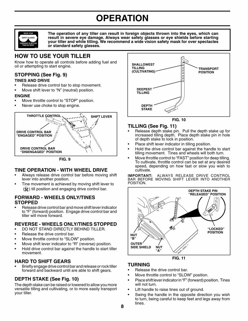
HOW TO USE YOUR TILLERKnow how to operate all controls before adding fuel and oil or attempting to start engine.
STOPPING (See Fig. 9)TINES AND DRIVE• Release drive control bar to stop movement.• Move shift lever to “N” (neutral) position.ENGINE• Move throttle control to “STOP” position.• Never use choke to stop engine.
TINE OPERATION - WITH WHEEL DRIVE• Always release drive control bar before moving shift
lever into another position.• Tine movement is achieved by moving shift lever to ( ) till position and engaging drive control bar.
FORWARD - WHEELS ONLY/TINES STOPPED• Release drive control bar and move shift lever in di ca tor
to “F” (forward) position. Engage drive control bar and tiller will move forward.
REVERSE - WHEELS ONLY/TINES STOPPED• DO NOT STAND DIRECTLY BEHIND TILLER.• Release the drive control bar.• Move throttle control to “SLOW” position.• Move shift lever indicator to “R” (reverse) position.• Hold drive control bar against the handle to start tiller
movement.
HARD TO SHIFT GEARS• Briefl y engage drive control bar and release or rock tiller
forward and backward until are able to shift gears.
DEPTH STAKE (See Fig. 10)The depth stake can be raised or lowered to allow you more versatile tilling and cul ti vat ing, or to more easily transport your tiller.
FIG. 9
depth_stake_2
TILLING (See Fig. 11)• Release depth stake pin. Pull the depth stake up for
increased tilling depth. Place depth stake pin in hole of depth stake to lock in position.
• Place shift lever indicator in tilling position.• Hold the drive control bar against the handle to start
tilling movement. Tines and wheels will both turn.• Move throttle control to “FAST” position for deep tilling.
To cultivate, throttle control can be set at any desired speed, depending on how fast or slow you wish to cultivate.
IMPORTANT: ALWAYS RELEASE DRIVE CONTROL BAR BEFORE MOVING SHIFT LEVER INTO ANOTHER POSITION.
TRANSPORTPOSITION
DEEPEST TILLING
DEPTHSTAKE
SHALLOWESTTILLING (CULTIVATING)
FIG. 10
The operation of any tiller can result in foreign objects thrown into the eyes, which can result in severe eye damage. Always wear safety glasses or eye shields before starting your tiller and while tilling. We recommend a wide vision safety mask for over spectacles or standard safety glasses.
DRIVE CONTROL BAR“ENGAGED” PO SI TION
SHIFT LEVERTHROT TLE CONTROL
DRIVE CONTROL BAR“DISENGAGED” PO SI TION
depth
_stak
e_1
NUT “B”
NUT “A”
OUTERSIDE SHIELD
DEPTH STAKE PIN“RELEASED” POSITION
“LOCKED”POSITION
FIG. 11

9
OPERATION
engine_art_4
OIL LEVEL
OIL DRAINPLUG
OIL FILLERPLUG
FIG. 12
BEFORE STARTING ENGINEIMPORTANT: BE VERY CAREFUL NOT TO ALLOW DIRT TO ENTER THE ENGINE WHEN CHECKING OR ADDING OIL OR FUEL. USE CLEAN OIL AND FUEL AND STORE IN AP PROVED, CLEAN, COVERED CONTAINERS. USE CLEAN FILL FUNNELS.
CHECK ENGINE OIL LEVEL (See Fig.12)• The engine in your unit has been shipped, from the
factory, already fi lled with SAE 30 summer weight oil.• With engine level, clean area around oil fi ller plug and
remove plug.• Engine oil should be to point of overfl owing when engine
is level. For ap proxi mate capacity see “PROD UCT SPEC I FI CA TIONS” on page 3 of this manual. All oil must meet A.P.I. Service Classifi cation SG-SL.
• For cold weather operation you should change oil for easier starting (See oil viscosity chart in the Mainte-nance sec tion of this manual).
• To change engine oil, see the Maintenance section in this manual.
TO START ENGINE (See Fig. 13)
CAUTION: Keep drive control bar in “DISENGAGED” position when start- ing en gine.
When starting engine for the fi rst time or if engine has run out of fuel, it will take extra pulls of the recoil starter to move fuel from the tank to the engine.• Make sure spark plug wire is prop er ly connected.• Move shift lever indicator to “N” (neutral) position.• Place throttle control in “FAST” position.
ADD GASOLINE • Fill fuel tank to bottom of fi ller neck. Do not overfi ll.
Use fresh, clean, regular un lead ed gasoline with a minimum of 87 octane. (Use of leaded gasoline will increase carbon and lead oxide deposits and reduce valve life). Do not mix oil with gasoline. Purchase fuel in quan ti ties that can be used within 30 days to assure fuel freshness.
CAUTION: Fill to within 1/2 inch of top of fuel tank to prevent spills and to allow for fuel expansion. If gasoline is ac- ci den tal ly spilled, move machine away from area of spill. Avoid creating any source of ignition until gasoline vapors have disappeared. Wipe off any spilled oil or fuel. Do not store, spill or use gasoline near an open fl ame.
IMPORTANT: WHEN OPERATING IN TEMPERATURES BELOW32°F(0°C), USE FRESH, CLEAN WINTER GRADE GAS O LINE TO HELP INSURE GOOD COLD WEATHER START ING.
CAUTION: Alcohol blended fuels (called gas o hol or using ethanol or methanol) can at-tract moisture which leads to sep a ra tion and for ma tion of acids during storage. Acidic gas can damage the fuel system of an engine while in storage. To avoid engine problems, the fuel system should be emptied before stor age of 30 days or longer. Drain the gas tank, start the engine and let it run until the fuel lines and carburetor are empty. Use fresh fuel next sea son. See Storage In struc tions for additional information. Never use engine or carburetor cleaner products in the fuel tank or permanent damage may occur.
• When you have completed your turn-around, release the drive control bar and lower handle. Place shift lever in till position and move throttle control to de sired speed. To begin tilling, hold drive control bar against the handle.
OUTER SIDE SHIELDS (See Fig. 11)The back edges of the outer side shields are slotted so that the shields can be raised for deep tilling and low ered for shal low tilling to protect small plants from being buried. Loosen nut “A” in slot and nut “B”. Move shield to desired position (both sides). Retighten nuts.
TO TRANSPORT
CAUTION: Before lifting or trans port ing, allow tiller engine and muffl er to cool. Disconnect spark plug wire. Drain gasoline from fuel tank.
AROUND THE YARD• Release the depth stake pin. Move the depth stake
down to the top hole for transporting the tiller. Place depth stake pin in hole of depth stake to lock in posi-tion. This prevents tines from scuffi ng the ground.
• Place shift lever indicator in “F” (forward) position for transporting.
• Hold the drive control bar against the handle to start tiller movement. Tines will not turn.
• Move throttle control to desired speed.
AROUND TOWN• Disconnect spark plug wire.• Drain fuel tank.• Transport in upright position to prevent oil leakage.

10
engine_art_71
RUN CHOKE
OPERATION
• Soil conditions are important for proper tilling. Tines will not readily penetrate dry, hard soil which may con trib ute to excessive bounce and diffi cult handling of your tiller. Hard soil should be mois tened before tilling; however, extremely wet soil will “ball-up” or clump during tilling. Wait until the soil is less wet in order to achieve the best results. When tilling in the fall, re move vines and long grass to prevent them from wrapping around the tine shaft and slowing your tilling operation.
• Do not lean on handle. This takes weight off the wheels and reduces traction. To get through a really tough section of sod or hard ground, apply upward pressure on handle or lower the depth stake.
3 2 1
5
4
6 7
FIG. 14
CULTIVATINGCultivating is destroying the weeds between rows to pre- vent them from robbing nourishment and moisture from the plants. At the same time, breaking up the upper layer of soil crust will help retain moisture in the soil. Best digging depth is 1" to 3" (2.5-7.5 cm). Lower the outer side shields to protect small plants from being buried.• Cultivate up and down the rows at a speed which will
allow tines to uproot weeds and leave the ground in rough condition, promoting no further growth of weeds and grass (See Fig. 15).
FIG. 15
TILLING HINTS
CAUTION: Until you are accustomed to handling your tiller, start actual fi eld use with throttle in slow position (mid-way between “FAST” and “IDLE”).
• Tilling is digging into, turning over, and breaking up packed soil before planting. Loose, unpacked soil helps root growth. Best tilling depth is 4" to 6" (10-15 cm). A tiller will also clear the soil of unwanted vege ta tion. The de com po si tion of this vegetable mat ter enriches the soil. Depending on the climate (rain fall and wind), it may be advisable to till the soil at the end of the growing season to further condition the soil.
• You will fi nd tilling much easier if you leave a row un-tilled between passes. Then go back between tilled rows. (See Fig. 14) There are two reasons for doing this. First, wide turns are much easier to negotiate than about-faces. Sec ond, the tiller won’t be pulling itself, and you, toward the row next to it.
FIG. 13
TINE SHEAR PINSThe tine assemblies on your tiller are secured to the tine shaft with shear pins (See “TINE REPLACEMENT” in the Service and Ad just ments section of this manual).
If the tiller is unusually overloaded or jammed, the shear pins are designed to break before internal damage occurs to the trans mis sion.• If shear pin(s) break, replace only with those shown in
the Repair Parts section of this manual.
CHOKE CONTROL
RECOIL STARTER HANDLE
• Turn fuel shut-off valve 1/4 turn to open position.• Move choke control to choke position.• Grasp recoil starter handle with one hand and grasp
tiller handle with other hand. Pull rope out slowly until engine reaches start of com pres sion cycle (rope will pull slightly harder at this point).
• Pull recoil starter handle quickly. Do not let starter handle snap back against starter.
• If engine fi res but does not start, move choke control to half choke position. Pull recoil starter handle until engine starts.
• When engine starts, slowly move choke control to "RUN" position as engine warms up.
NOTE: A warm engine requires less choking to start.• Move throttle control to desired running position.• Allow engine to warm up for a few minutes before
engaging tines.
NOTE: If at a high altitude (3000 feet) or in cold tem per a tures (below 32°F), the carburetor fuel mixture may need to be adjusted for best engine performance. See "TO AD JUST CARBURETOR" in the Service and Adjustments section of this manual.
NOTE: If engine does not start, see troubleshooting points.

11
MAINTENANCE
GENERAL RECOMMENDATIONSThe warranty on this tiller does not cover items that have been subjected to operator abuse or negligence. To receive full value from the warranty, the operator must main tain tiller as instructed in this manual.
Some adjustments will need to be made periodically to properly maintain your tiller.
All adjustments in the Service and Adjustments section of this manual should be checked at least once each season.• Once a year you should replace the spark plug, clean
or replace air fi lter, and check tines and belts for wear. A new spark plug and clean air fi lter assure proper air-fuel mixture and help your engine run better and last longer.
BEFORE EACH USE• Check engine oil level.• Check tine operation.• Check for loose fasteners.
LUBRICATIONKeep unit well lubricated (See “LUBRICATION CHART”).
SAE 30 OR 10W-30 MOTOR OIL REFER TO MAINTENANCE “EN GINE” SECTIONEP #1 GREASE
LUBRICATION CHART
WHEEL HUB
ENGINE
THROT TLE CONTROL
IDLER BRACKET
LEVELING SHIELD HINGES
DEPTH STAKE PIN
RH GEAR CASE GREASE FITTIG
MAINTENANCESCHEDULE
FILL IN DATESAS YOU COMPLETEREGULAR SERVICE
Check Engine Oil Level
Change Engine Oil
Oil Pivot Points
Inspect Air Screen
Inspect Spark Arrester / Muffler
Clean or Replace Air Cleaner Cartridge
Clean Engine Cylinder Fins
Replace Spark Plug
BE
FOR
E E
AC
H U
SE
EV
ER
Y 2
5 H
OU
RS
EV
ER
Y 5
HO
UR
SE
VE
RY
50
HO
UR
S
SERVICE DATES
1,2
2
1 - Change more often when operating under a heavy load or in high ambient temperatures.2 - Service more often when operating in dirty or dusty conditions.
EV
ER
Y S
EA
SO
NRH Gear Case Grease Fitting (1oz.)

12
MAINTENANCE
OIL FILLERPLUG
OIL LEVEL
OIL DRAINPLUG
FIG. 16
Disconnect spark plug wire before performing any maintenance (except car bu re tor adjustment) to prevent accidental start ing of engine.Prevent fi res! Keep the engine free of grass, leaves, spilled oil, or fuel. Re move fuel from tank before tipping unit for maintenance. Clean muffl er area of all grass, dirt, and debris. Do not touch hot muffl er or cylinder fi ns as contact may cause burns.
FIG. 17
TO CHANGE ENGINE OIL (See Figs. 16 and 17)Determine temperature range expected before oil change. All oil must meet API service classifi cation SG-SL.• Be sure tiller is on level surface.• Oil will drain more freely when warm.• Use a funnel to prevent oil spill on tiller, and catch oil
in a suitable con tain er.• Remove drain plug. For easier removal of plug use 7/16 12 Pt. socket with extension.)• Tip tiller forward to drain oil.• After oil has drained completely, replace oil drain plug
and tighten securely.• Remove oil fi ller plug. Be careful not to allow dirt to
enter the engine.• Refi ll engine with oil. See “CHECK ENGINE OIL LEVEL”
in the Operation section of this manual.
ENGINE
LUBRICATIONUse only high quality detergent oil rated with API service classifi cation SG-SL. Select the oil’s SAE vis cos i ty grade according to your expected temperature.
NOTE: Although multi-viscosity oils (5W-30, 10W-30, etc.) improve starting in cold weather, these multi-viscosity oils will result in increased oil consumption when used above 40°F (4°C). Check your engine oil level more frequently to avoid possible engine damage from running low on oil.
Change the oil after every 25 hours of operation or at least once a year if the tiller is not used for 25 hours in one year.
Check the crankcase oil level before starting the engine and after each fi ve (5) hours of continuous use. Add SAE 30 motor oil or equivalent. Tighten oil fi ller plug securely each time you check the oil level.
TEMPERATURE RANGE ANTICIPATED BEFORE NEXT OIL CHANGE
SAE VISCOSITY GRADES
-20 0 30 40 80 100
-30 -20 4 20 30 40
F
C -10 10
60
10W-30 / 5W-30
SAE 30
oil_visc_chart5_e(drt)
AIR CLEANER (See Fig. 18) Service air cleaner cartridge every twenty-fi ve hours, more often if engine is used in very dusty conditions.• Loosen air cleaner screws, one on each side of
cover.• Remove air cleaner cover.• Carefully remove air cleaner cartridge. Be care ful. Do
not allow dirt or de bris to fall into carburetor.• Clean by tapping gently on a fl at surface.• If very dirty or damaged, replace cartridge.• Clean and re place cover. Tighten screws securely.
CAUTION: Petroleum sol vents, such as kerosene, are not to be used to clean cartridge. They may cause de te ri o ra tion of the cartridge. Do not oil car tridge. Do not use pres sur ized air to clean or dry cartridge.

13
MAINTENANCEMUFFLERDo not operate tiller without muffl er. Do not tamper with exhaust system. Damaged muffl ers or spark arresters could create a fi re hazard. Inspect pe ri odi cally and re place if nec es sary. If your engine is equipped with a spark arrester screen assembly, re move every 50 hours for cleaning and inspection. Re place if dam aged.
SPARK PLUGReplace spark plugs at the beginning of each tilling sea- son or after every 50 hours of use, whichever comes fi rst. Spark plug type and gap setting is shown in “PRODUCT SPEC I FI CA TIONS” on page 3 of this manual.
TRANSMISSIONOnce a season, lubricate the right hand side gear case grease fi tting with 1 oz. of EP #1 Grease.
CLEANINGDo not clean your tiller when the engine and transmission are hot. We do not rec om mend using pressurized water (gar den hose, etc.) to clean your unit un less the gasket area around the trans mis sion and the engine muf fl er, air fi l ter and car bu re tor are cov ered to keep wa ter out. Wa ter in en gine will short en the useful life of your tiller. • Clean engine, wheels, fi nish, etc. of all foreign mat-
ter.• Keep fi nished surfaces and wheels free of all gas o line,
oil, etc.• Protect painted surfaces with au to mo tive type wax.
AIR CLEANER SCREW
COV ER
AIR CLEAN ER CAR TRIDGE
FIG. 18
engine_art_71
BLOWER HOUSING
AIR SCREEN
CYLINDER FINS
MUF FLER
FIG. 19
COOLING SYSTEM (See Fig. 19) Your engine is air cooled. For proper engine performance and long life keep your engine clean.• Clean air screen frequently using a stiff-bristled-
brush.• Remove blower housing and clean as nec es sary.• Keep cylinder fi ns free of dirt and chaff.
14
SERVICE AND ADJUSTMENTS
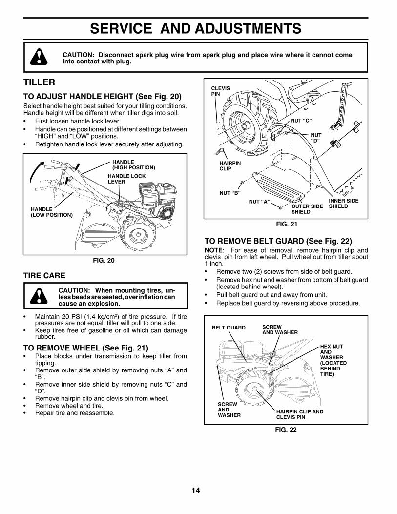
CAUTION: Disconnect spark plug wire from spark plug and place wire where it cannot come into contact with plug.
TILLER
TO ADJUST HANDLE HEIGHT (See Fig. 20)Select handle height best suited for your tilling conditions. Handle height will be different when tiller digs into soil.• First loosen handle lock lever.• Handle can be positioned at different settings between
“HIGH” and “LOW” positions.• Retighten handle lock lever securely after adjusting.
FIG. 20
HANDLE (LOW POSITION)
TIRE CARE
CAUTION: When mounting tires, un- less beads are seated, over in fl a tion can cause an explosion.
• Maintain 20 PSI (1.4 kg/cm2) of tire pressure. If tire pres sures are not equal, tiller will pull to one side.
• Keep tires free of gasoline or oil which can damage rubber.
TO REMOVE WHEEL (See Fig. 21)• Place blocks under trans mis sion to keep tiller from
tipping.• Remove outer side shield by removing nuts “A” and
“B”.• Remove inner side shield by removing nuts “C” and
“D”. • Remove hairpin clip and clevis pin from wheel.• Remove wheel and tire.• Repair tire and reassemble.
tire_4
CLEVIS PIN
IN NER SIDE SHIELDOUTER SIDE
SHIELD
NUT “D”
HAIR PIN CLIP
NUT “C”
NUT “A”
NUT “B”
FIG. 21
HANDLE LOCKLEVER
HANDLE(HIGH POSITION)
FIG. 22
SCREWAND WASHER
HEX NUTAND WASHER(LOCATED BEHINDTIRE)
BELT GUARD SCREWAND WASHER
HAIRPIN CLIP ANDCLEVIS PIN
TO REMOVE BELT GUARD (See Fig. 22)NOTE: For ease of removal, remove hairpin clip and clevis pin from left wheel. Pull wheel out from tiller about 1 inch.• Remove two (2) screws from side of belt guard.• Remove hex nut and washer from bottom of belt guard
(located behind wheel).• Pull belt guard out and away from unit.• Replace belt guard by reversing above procedure.

15
SERVICE AND ADJUSTMENTS
CABLE CLIPSCREW
DRIVECONTROLCABLE
EXTENSIONSPRING
ENGINEPULLEY
IDLERPULLEY TRANS MIS SION PULLEY
LESS TEN SION
5/8"MORETEN SION
TO REPLACE GROUND DRIVE BELT (See Fig. 23)• Remove belt guard (See “TO REMOVE BELT GUARD”
in this section of this manual).• Remove old belt by slipping off engine pulley fi rst then
remove from transmission pulley.• Place new belt in groove of transmission pulley and
into engine pulley. BELT MUST BE IN GROOVE ON TOP OF IDLER PULLEY. NOTE POSITION OF BELT TO GUIDES.
• Check belt adjustment as described below.• Replace belt guard.• Reposition wheel and replace clevis pin and hairpin
clip.
FIG. 23
GROUND DRIVE BELT ADJUSTMENT (See Fig. 23)For proper belt tension, the extension spring should have about 5/8 inch stretch when drive control bar is in “EN GAGED” position. This tension can be attained as follows:• Loosen cable clip screw securing the drive control
cable.• Slide cable forward for less tension and rearward for
more tension until about 5/8 inch stretch is obtained while the drive control bar is engaged.
• Tighten cable clip screw securely.

16
tine_13
tine_3
SERVICE AND ADJUSTMENTS
FIG. 26
TINE REPLACEMENT (See Figs. 24, 25, and 26)
CAUTION: Tines are sharp. Wear gloves or other protection when han- dling tines.
A badly worn tine causes your tiller to work harder and dig more shallow. Most important, worn tines cannot chop and shred organic matter as effectively nor bury it as deeply as good tines. A tine this worn needs to be replaced.
FIG. 25
• To maintain the superb tilling performance of this ma chine the tines should be checked for sharpness, wear, and bending, particularly the tines which are next to the transmission. If the gap between the tines ex ceeds 3-1/2 inches (9 cm), they should be replaced or straight ened as necessary.
• New tines should be assembled as shown in Fig. 26. Sharp ened tine edges will rotate rearward from above.
TINE TINE
3-1/2" MAX (9 CM)
SHARP EDGE
HAIRPIN CLIP
SHARP EDGES
COUNTERTINEROTATION
0205
0
SHARP EDGES SHARP EDGE
SHEAR PIN
SHEAR PIN
HAIRPIN CLIP
FIG. 24
NEW TINE WORN TINE
SHARP EDGE

17
SERVICE AND ADJUSTMENTS
FIG. 27
engine_art_78
THROTTLE CONTROL
CLAMP SCREW
CASING AND WIRE
ENGINE
TO ADJUST THROTTLE CONTROL CABLE (See Fig. 27)The throttle control has been preset at the factory and ad just ment should not be necessary. If adjustment is necessary, proceed as follows:• With engine not running, move remote throttle control
lever to “FAST” position.• If throttle lever on engine touches high speed stop, no
further adjustment is necessary. If throttle lever does not touch high speed stop, continue with adjustment procedure.
• Loosen cable clamp screw.• Move throttle lever up until it touches high speed stop,
and hold in this position.• Tighten cable clamp screw securely.
TO AD JUST CARBURETORThe carburetor has been preset at the factory and ad just ment should not be necessary. However, engine per for mance can be affected by dif fer enc es in fuel, tem per a ture, al ti tude or load. If the carburetor does need ad just ment, contact your nearest authorized service center/de part mentIMPORTANT: NEVER TAMPER WITH THE ENGINE GOVERNOR, WHICH IS FACTORY SET FOR PROPER ENGINE SPEED. OVER SPEED ING THE ENGINE ABOVE THE FACTORY HIGH SPEED SETTING CAN BE DANGEROUS. IF YOU THINK THE ENGINE-GOVERNED HIGH SPEED NEEDS ADJUSTING, CONTACT YOUR NEAREST AUTHORIZED SERVICE CENTER/DEPARTMENT, WHICH HAS THE PROPER EQUIP MENT AND EXPERIENCE TO MAKE ANY NEC ES SARY ADJUSTMENTS.

18
Immediately prepare your tiller for storage at the end of the season or if the unit will not be used for 30 days or more.
WARNING: Never store the tiller with gasoline in the tank inside a build ing where fumes may reach an open fl ame or spark. Allow the engine to cool before storing in any en clo sure.
TILLER• Clean entire tiller (See “CLEANING” in the Maintenance
section of this manual).• Inspect and replace belts, if necessary (See belt re-
place ment instructions in the Service and Ad just ments section of this manual).
• Lubricate as shown in the Maintenance section of this manual.
• Be sure that all nuts, bolts and screws are securely fastened. Inspect moving parts for damage, break age and wear. Replace if necessary.
• Touch up all rusted or chipped paint surfaces; sand lightly before painting.
ENGINE
FUEL SYSTEMIMPORTANT: IT IS IMPORTANT TO PREVENT GUM DEPOSITS FROM FORMING IN ES SEN TIAL FUEL SYS TEM PARTS SUCH AS THE CAR BU RE TOR, FUEL FILTER, FUEL HOSE, OR TANK DURING STOR AGE. ALSO, EXPERIENCE INDICATES THAT AL CO HOL BLENDED FUELS (CALLED GASOHOL OR USING ETHA NOL OR METHA NOL) CAN ATTRACT MOIS TURE WHICH LEADS TO SEPA RA TION AND FORMATION OF ACIDS DUR ING STOR AGE. ACIDIC GAS CAN DAMAGE THE FUEL SYSTEM OF AN ENGINE WHILE IN STOR AGE.• Empty the fuel tank by starting the engine and let it run
until the fuel lines and carburetor are empty.• Never use engine or carburetor cleaner products in the
fuel tank or permanent.• Use fresh fuel next season.NOTE: Fuel stablizer is an acceptable alternative inminimizing the formation of fuel gum deposits duringstorage. Add stabilizer to gasoline in fuel tank or storagecontainer. Always follow the mix ratio found on stablizercontainer. Run engine at least 10 minutes after addingstablizer to allow the stabilizer to reach the carburetor. Do not empty the gas tank and carburetor if using fuelstabilizer.
ENGINE OILDrain oil (with engine warm) and replace with clean oil. (See “ENGINE” in the Maintenance section of this man ual).
CYLINDER(S)• Remove spark plug.• Pour 1 ounce (29 ml) of oil through spark plug hole into
cylinder.• Pull starter handle slowly several times to distribute
oil.• Replace with new spark plug.
OTHER• Do not store gasoline from one season to an-
other. • Replace your gasoline can if your can starts to rust.
Rust and/or dirt in your gasoline will cause problems.• If possible, store your unit indoors and cover it to give
protection from dust and dirt.• Cover your unit with a suitable protective cover that
does not retain moisture. Do not use plastic. Plastic cannot breathe which allows condensation to form and will cause your unit to rust.
IMPORTANT: NEVER COVER TILLER WHILE EN GINE AND EX HAUST AREAS ARE STILL WARM.
STORAGE

19
Will not start 1. Out of fuel. 1. Fill fuel tank. 2. Engine not “CHOKED” properly. 2. See “TO START ENGINE” in Operation section. 3. Engine fl ooded. 3. Wait several minutes before attempting to start. 4. Dirty air cleaner. 4. Clean or replace air cleaner cartridge. 5. Water in fuel. 5. Empty fuel tank and carburetor, and refi ll tank with fresh, clean gasoline. 6. Clogged fuel tank. 6. Remove fuel tank and clean. 7. Loose spark plug wire. 7. Make sure spark plug wire is seated properly on plug. 8. Bad spark plug or improper gap. 8. Replace spark plug or adjust gap. 9. Carburetor out of adjustment. 9. Make necessary adjustments. 10. Oil soaked air fi lter. 10. Replace air fi lter.
Hard to start 1. Throttle control not set properly. 1. Place throttle control in “FAST” position. 2. Dirty air cleaner. 2. Clean or replace air cleaner cartridge. 3. Bad spark plug or improper gap. 3. Replace spark plug or adjust gap. 4. Stale or dirty fuel. 4. Empty fuel tank and refi ll tank with fresh, clean gasoline. 5. Loose spark plug wire. 5. Make sure spark plug wire is seated properly on plug. 6. Carburetor out of adjustment. 6. Make necessary adjustments.
Loss of power 1. Engine is overloaded. 1. Set depth stake for shallower tilling. 2. Dirty air cleaner. 2. Clean or replace air cleaner cartridge. 3. Low oil level/dirty oil. 3. Check oil level/change oil. 4. Faulty spark plug. 4. Clean and regap or change spark plug. 5. Oil in fuel. 5. Empty and clean fuel tank and refi ll tank, and clean car bu re tor. 6. Stale or dirty fuel. 6. Empty fuel tank and refi ll tank with fresh, clean gasoline. 7. Water in fuel. 7. Empty fuel tank and carburetor, and refi ll tank with fresh, clean gasoline. 8. Clogged fuel tank. 8. Remove fuel tank and clean. 9. Spark plug wire loose. 9. Connect and tighten spark plug wire. 10. Dirty engine air screen. 10. Clean engine air screen. 11. Dirty/clogged muffl er. 11. Clean/replace muffl er. 12. Carburetor out of adjustment. 12. Make necessary adjustments. 13. Poor compression. 13. Contact an authorized service center/department.
Engine overheats 1. Low oil level/dirty oil. 1. Check oil level/change oil. 2. Dirty engine air screen. 2. Clean engine air screen. 3. Dirty engine. 3. Clean cylinder fi ns, air screen, and muffl er area. 4. Partially plugged muffl er. 4. Remove and clean muffl er. 5. Improper carburetor adjustment. 5. Adjust carburetor to richer position.
Excessive bounce/ 1. Ground too dry and hard. 1. Moisten ground or wait for more favorable soil diffi cult handling conditions.
Soil balls up or clumps 1. Ground too wet. 1. Wait for more favorable soil conditions.
Engine runs but tiller 1. Drive control bar is not engaged. 1. Engage drive control.won’t move 2. V-belt not correctly adjusted. 2. Inspect/adjust V-belt. 3. V-belt is off pulley(s). 3. Inspect V-belt.
Engine runs but labors 1. Tilling too deep. 1. Set depth stake for shallower tilling. when tilling 2. Throttle control not properly adjusted. 2. Check throttle control setting. 3. Carburetor out of adjustment. 3. Make necessary adjustments.
Tines will not rotate 1. Shear pin(s) broken. 1. Replace shear pin(s).
PROBLEM CAUSE CORRECTION
TROUBLESHOOTING POINTS

20
REPAIR PARTSTILLER - - MODEL NUMBER 650RTT (96093000201), PRODUCT NUMBER 960 93 00-02HANDLE ASSEMBLY
KEY PART NO. NO. DESCRIPTION20 532 10 92-28 Lever, Lock, Handle21 532 18 11-27 Handle23 532 08 67-77 Screw, Slotted, Hex Washer Head #10-24 x 1/224 532 00 94-84 Clip26 532 15 92-31 Cable, Clutch27 873 90 04-00 Nut, Hex, Flanged 1/4-2029 873 73 10-00 Nut, Hex, Keps #10-24 30 532 10 41-64 Tie, Cable31 532 15 06-96 Bolt, Pivot33 872 14 04-04 Bolt, Carriage 1/4-20 x 1/237 532 10 26-04 Grip, Control Bar41 532 10 27-44 Clamp, Control BarNOTE: All component dimensions given in U.S. inches.
1 inch = 25.4 mm
KEY PART NO. NO. DESCRIPTION1 532 18 94-82 Control, Throttle2 532 00 92-66 Grip, Handle4 532 15 92-28 Control Bar Assembly6 532 18 06-76 Panel, Control8 871 19 10-08 Screw, Truss Head #10-24 x 1/210 532 12 47-97 Grip, Handle11 532 12 47-88 Clip, Hairpin12 532 08 13-28 Bolt, Shoulder13 532 18 74-97 Handle, Shift14 532 10 93-13 Grommet, Rubber15 532 10 93-37 Rod, Shift16 872 11 06-08 Bolt, Carriage, Grade 5 3/8-16 x 117 532 10 92-29 Lock, Handle 18 873 68 06-00 Nut, Crownlock 3/8-1619 819 13 16-11 Washer 13/32 x 1 x 11 Gauge
1
332
2
6
30
8
27
2426
23
15
11
1012 13
21
1918
31
17
16
11
20
29
2741
37
37
4
14

21
65
3 2
3 2
65
67 3431
30
283
40 2615
66
44
4027
19
16
38
421
14
3233
36
13
37
396
5
8
12
7 9
10
2922
mainframe_left_17
24
23
25
REPAIR PARTSTILLER - - MODEL NUMBER 650RTT (96093000201), PRODUCT NUMBER 960 93 00-02MAINFRAME, LEFT SIDE
KEY PART NO. NO. DESCRIPTION
25 532 12 47-88 Clip, Hairpin26 532 16 67-92 Guard, Belt27 532 13 28-01 Belt, V28 532 10 46-79 Pulley, Idler29 812 00 00-32 Ring, Klip30 532 15 92-29 Bracket, Idler31 532 10 23-84 Bolt, Hex Head 5/16-16 x 1232 532 10 21-41 Shaft, Idler Arm33 874 76 06-16 Bolt, Hex 3/8-16 x 134 532 10 23-83 Counterweight, LH35 874 76 05-24 Bolt, Hex Head 5/16-18 x 1-1/236 532 10 23-31 Bracket, Reinforcement, LH37 532 13 08-12 Sheave, Engine38 874 76 05-44 Bolt, Hex Head 5/16-18 x 2-3/4 39 532 14 00-62 Cap, Plunger, Black40 532 17 04-88 Screw, Slotted, Hex Washer Head #10-24 x 1/244 873 80 05-00 Locknut, Hex, with Insert 5/16-1865 873 97 05-00 Nut, Hex, Flangelock66 819 13 13-12 Washer 13/32 x 13/16 x 12 Gauge
NOTE: All component dimensions given in U.S. inches.1 inch = 25.4 mm
KEY PART NO. NO. DESCRIPTION
1 873 97 05-00 Nut, Hex, Flangelock 5/162 810 04 06-00 Washer, Lock 3/83 873 22 06-00 Nut, Hex 3/8-164 532 17 01-27 Shield, Inner Belt Guard, RH5 532 16 43-29 Pin, Spiral, Flared6 532 11 01-11 Lever, Shift7 872 11 04-04 Bolt, Carriage, Grade 5 1/4-20 x 1/28 532 00 87-00 Plate, Shift Indicator9 532 08 67-77 Screw, Slotted, Hex Washer Head
#10-24 x 1/210 532 00 94-84 Clip12 873 51 04-00 Nut, Hex, Keps 1/4-2013 823 23 05-06 Set Screw, Hex 5/16-18 x 3/814 532 11 06-52 Spacer, Split 0.327 x 0.42 x 2.0915 819 11 11-16 Washer 11/32 x 11/16 x 16 Gauge16 532 14 51-02 Sheave, Transmission19 812 00 00-28 Retainer Ring21 532 15 61-17 Spacer, Split 22 874 77 05-08 Bolt, Hex Head 5/16-24 x 1/223 532 00 50-15 Tire- - 532 12 43-66 Rim- - 532 12 47-18 Valve, Tire24 532 12 68-75 Rivet, Drilled

22
KEY PART NO. NO. DESCRIPTION
KEY PART NO. NO. DESCRIPTION
REPAIR PARTSTILLER - - MODEL NUMBER 650RTT (96093000201), PRODUCT NUMBER 960 93 00-02MAINFRAME, RIGHT SIDE
2 873 97 05-00 Locknut, Hex, Flange 5/16-185 532 10 23-32 Bracket, Reinforcement7 532 10 21-73 Counter Weight, R.H.8 810 04 06-00 Washer, Lock 3/89 873 22 06-00 Nut, Hex 3/8-1610 874 76 05-24 Bolt, Hex 5/16-18 x 1-1/211 532 12 47-88 Clip, Hairpin12 532 12 68-75 Rivet, Drilled
13 532 00 50-15 Tire- - 532 12 43-66 Rim- - 532 12 47-18 Tire Valve15 - - - Engine, Briggs & Stratton, Model
Number 120302 (For engine service and replacement parts, call Briggs & Stratton at 1-800-233-3723)
NOTE: All component dimensions given in U.S. inches. 1 inch = 25.4 mm
5
1078
911
12
13
15
2
10

23
KEY PART NO. NO. DESCRIPTION
1 532 18 85-54 Transmission Assembly (In cludes Key Numbers 2 through 53)
2 532 18 84-82 Gearcase, LH, with Bearing (In cludes Key Number 4)3 532 16 19-63 Gasket, Gearcase4 532 00 50-20 Bearing, Needle5 532 00 13-70 Washer, Thrust 5/8 x 1.10 x 1/326 532 13 73-35 Pinion, Input7 532 14 51-01 Shaft, In put8 532 12 47-92 Bearing, Needle9 532 15 44-67 Washer, Seal10 532 12 46-97 Ball, Steel11 532 10 03-71 Spring, Shift, Fork12 532 10 61-60 O-Ring13 532 14 21-45 Arm, Shift14 532 00 83-53 Fork, Shift15 812 00 00-39 Ring, Klip16 532 15 44-66 Shaft, Shift18 532 00 43-58 Washer19 812 00 00-40 Ring, Klip20 532 10 21-14 Gear, As sem bly, Reverse Idler
(Includes Key Numbers 21 and 22)21 532 10 21-15 Gear, Re verse Idler22 532 00 68-03 Bearing, Needle23 532 10 21-11 Shaft, Re verse Idler24 810 04 07-00 Washer, Lock 7/16
KEY PART NO. NO. DESCRIPTION
25 873 61 07-00 Nut, Hex 7/16-2027 532 14 30-09 Bearing, Shaft, Ground Drive LH28 532 10 63-90 Spacer 0.765 x 1.125 x 1.2329 532 10 21-34 Chain #35-50 Pitch30 532 15 07-37 Ground Shaft Assembly31 532 14 30-08 Bearing, Shaft, Ground Drive, RH32 532 10 63-88 Spacer 0.70 x 1.00 x 1.15033 532 10 21-21 Sprocket and Gear Assembly34 532 10 21-12 Shaft, Re duc tion (2nd)35 532 10 21-01 Screw, Whizlock 5/16-18 x 3-1/236 532 15 43-55 Sprocket Assembly with Bearing (Includes Key Numbers 37 and 38)37 532 12 47-91 Bearing, Needle38 532 15 43-56 Sprocket, Tine39 532 10 53-45 Gear, Clus ter, Red, 1st & 2nd40 532 10 53-46 Gear, Re verse41 532 00 83-58 Shaft, Re duc tion (1st)42 532 00 42-20 Washer, Thrust43 532 10 61-46 Spacer 1.01 x 1.75 x 0.76044 532 15 52-36 Seal Assembly, Oil48 532 18 84-85 Gearcase, RH, with Bearing (In cludes Key Number 8)49 532 13 26-88 Shaft, Tine50 532 10 61-47 Chain, Roller #50-50 Pitch51 817 72 04-08 Screw 1/4-20 x 1/252 873 22 05-00 Nut, Hex 5/16-1853 532 16 51-40 Kit, Bearing58 532 17 95-20 Bolt, Shoulder 1/4-20 x 7/860 532 18 32-26 Fitting, Grease- - 532 00 60-66 Grease, Plastilube #1NOTE: All component dimensions given in U.S. inches.
1 inch = 25.4 mm
12
13 15
16
14
9
9
85 18
232221
1918
32
31
7
6
54
11
10
29
30
2818 32 33
3418
4860
24
44
18
4243
41
49
40
393738
37
50
36
20
25
27
35
2524
44
51 58
5352
53
REPAIR PARTSTILLER - - MODEL NUMBER 650RTT (96093000201), PRODUCT NUMBER 960 93 00-02TRANSMISSION
24
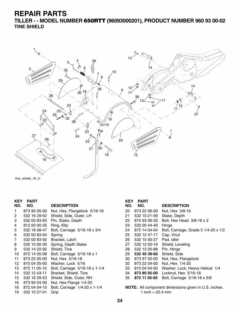
20 873 22 06-00 Nut, Hex 3/8-1621 532 10 21-56 Stake, Depth22 874 93 06-32 Bolt, Hex Head 3/8-16 x 223 532 00 44-40 Hinge24 872 14 04-04 Bolt, Carriage, Grade 5 1/4-20 x 1/225 532 12 47-17 Cap, Vinyl26 532 10 92-27 Pad, Idler27 532 12 50-16 Shield, Leveling28 532 12 05-88 Pin, Hinge29 532 40 39-60 Shield, Side30 873 97 05-00 Nut, Hex, Flangelock32 873 22 04-00 Nut, Hex 1/4-2033 810 04 04-00 Washer, Lock, Heavy Helical 1/434 873 80 05-00 Locknut, Hex 5/16-1835 872 11 05-05 Bolt, Carriage 5/16-18 x 5/8
NOTE: All component dimensions given in U.S. inches. 1 inch = 25.4 mm
KEY PART NO. NO. DESCRIPTION
KEY PART NO. NO. DESCRIPTION
1 873 90 05-00 Nut, Hex, Flangelock 5/16-182 532 16 29-52 Shield, Side, Outer, LH3 532 00 83-93 Pin, Stake, Depth4 812 00 00-35 Ring, Klip5 532 18 08-47 Bolt, Carriage 5/16-18 x 3/4 6 532 00 83-94 Spring7 532 00 83-92 Bracket, Latch8 532 10 92-30 Spring, Depth Stake9 532 14 22-92 Shield, Tine10 872 14 05-08 Bolt, Carriage 5/16-18 x 111 873 22 05-00 Nut, Hex 5/16-1812 810 04 05-00 Washer, Lock 5/1613 872 11 05-10 Bolt, Carriage 5/16-18 x 1-1/414 532 12 43-11 Bracket, Shield, Tine15 532 16 29-53 Shield, Side, Outer, RH16 873 90 04-00 Nut, Hex Flange 1/4-2018 872 04 04-10 Bolt, Carriage 1/4-20 x 1-1/4 19 532 10 27-01 Grip
REPAIR PARTSTILLER - - MODEL NUMBER 650RTT (96093000201), PRODUCT NUMBER 960 93 00-02TINE SHIELD
1
2
29
29
15
1
11
11
12
12
13
14
14
35
24
23
2627
22
21 20
19
11
12
1625
33
32
16
3 4
78
936
36
23
23
28
24
18
6
36
10
30
tine_shield_16_in
1211
37
36

25
KEY PART NO. NO. DESCRIPTION
KEY PART NO. NO. DESCRIPTION
1 532 00 44-59 Tine, Outer, LH2 532 13 26-73 Clevis Pin3 532 00 65-54 Tine, Inner, LH4 532 12 46-60 Retainer, Spring, Zinc-Plated5 532 13 27-27 Assembly, Hub and Plate, LH8 874 61 06-16 Bolt, Hex Head 3/8-24 x 1
9 532 00 44-60 Tine, Outer, RH10 532 13 27-28 Assembly, Hub and Plate, RH11 532 00 65-55 Tine, Inner, RH 34 873 54 06-00 Nut, Hex, Crownlock 3/8-24
NOTE: All component dimensions given in U.S. inches.1 inch = 25.4 mm
REPAIR PARTSTILLER - - MODEL NUMBER 650RTT (96093000201), PRODUCT NUMBER 960 93 00-02TINE ASSEMBLY
21111
10
9
94
4
534
3
3
1
2
1
1
1
9
9
8

26
1 532 18 90-19 Decal, Husqvarna, Belt Guard2 532 18 90-18 Decal, Husqvarna, Control Panel3 532 18 08-13 Decal, Tine Control4 532 18 92-33 Decal, Tine Shield5 532 11 06-14 Decal, Hand Placement 6 532 10 21-80 Decal, Shift Indicator7 532 16 23-84 Decal, Warning8 532 40 91-42 Decal, Engine, 8.75 9 532 12 00-76 Decal, Warning, Rotating Tines10 532 40 91-41 Decal, Engine, Fuel Tank, 8.7511 532 41 18-16 Decal, Rewind Starter, B&S - - 532 40 11-49 Owner’s Manual, English - - 532 40 11-50 Owner’s Manual, French
KEY PART NO. NO. DESCRIPTION
3
2
6
9
REPAIR PARTSTILLER - - MODEL NUMBER 650RTT (96093000201), PRODUCT NUMBER 960 93 00-02DECALS
5
7
8
10
114
1

27
SE
CT
ION
1:
LIM
ITE
D W
AR
RA
NT
Y
H
usqv
arna
For
est
& G
arde
n C
ompa
ny (
“Hus
qvar
na”)
war
rant
s H
usqv
arna
pro
duct
to
the
orig
inal
pur
-ch
aser
to
be f
ree
from
def
ects
in m
ater
ial a
nd w
orkm
ansh
ip f
rom
the
dat
e of
pur
chas
e fo
r th
e “W
arra
nty
Per
iod”
of
the
prod
uct
as s
et f
orth
bel
ow:
Lif
etim
e W
arra
nty
: A
ll til
ler
tines
aga
inst
bre
akag
e, t
rimm
er s
hafts
, ig
nitio
n co
ils a
nd m
odul
es o
n ha
nd
held
pro
d uct
.
3 Y
ear
War
ran
ty:
Spi
ndle
s (o
n Z
ero
Turn
Rid
ers
and
Com
mer
cial
Wal
k-B
ehin
ds)
2 Y
ear
CO
MM
ER
CIA
L-W
arra
nty
: H
usqv
arna
Com
mer
cial
Tur
f E
quip
men
t—ze
ro t
urn
rider
s, w
ide
area
w
alks
, an
d gr
ound
eng
agin
g co
mm
erci
al e
quip
men
t.
2 Y
ear
NO
N-C
OM
ME
RC
IAL
War
ran
ty: A
utom
atic
Mow
er, R
idin
g la
wn
mow
ers,
yar
d an
d ga
rden
trac
tors
, w
alk
behi
nd m
ower
s, t
iller
s, c
hain
saw
s, t
rimm
ers,
bru
shcu
tters
, cl
earin
g sa
ws,
sno
w b
low
ers,
han
dhel
d bl
ower
s, b
ackp
ack
blow
ers,
hed
ge t
rimm
ers,
ele
ctric
al p
rodu
cts
and
pow
er-a
ssis
t co
llect
ion
syst
ems
for
non c
om m
er ci
al,
nonp
rofe
ssio
nal,
noni
nstit
utio
nal o
r no
ninc
ome
prod
ucin
g us
e, e
xcep
t as
her
ein
stat
ed.
E
mis
sion
con
trol
sys
tem
com
pone
nts
nece
ssar
y to
com
ply
with
CA
RB
-TIE
R-I
I an
d E
PA
reg
ulat
ions
, ex
cept
for
thos
e co
mpo
nent
s w
hich
are
par
t of e
ngin
e sy
stem
s m
anuf
actu
red
by th
ird p
arty
eng
ine
man
u-fa
ctur
ers
for
whi
ch t
he p
urch
aser
has
rec
eive
d a
sepa
rate
war
rant
y w
ith p
rodu
ct in
form
atio
n su
pplie
d at
tim
e of
pur
chas
e.
1 Y
ear
War
ran
ty:
Pow
er c
utte
rs, s
tum
p gr
inde
r, po
le p
rune
rs a
nd p
ole
saw
s fo
r no
n-co
mm
erci
al, n
on-p
ro-
fess
iona
l, no
n-in
stitu
tiona
l or
non-
inco
me
prod
ucin
g us
e. A
ll tr
imm
ers,
bru
shcu
tters
, cle
arin
g sa
ws,
hov
er-
ing
trim
mer
s, s
tick
edge
rs, b
ackp
ack
blow
ers,
han
d he
ld b
low
ers,
hed
ge tr
imm
ers,
pow
er-a
ssis
t col
lect
ion
syst
ems
used
for
com
mer
cial
, in
stitu
tiona
l, pr
ofes
sion
al o
r in
com
e pr
oduc
ing
purp
oses
or
use.
Bat
teri
es h
ave
a on
e-ye
ar p
rora
ted
limite
d w
arra
nty
with
100
% r
epla
cem
ent
durin
g th
e fi r
st 6
mon
ths.
90 D
ay W
arra
nty
: A
utom
atic
Mow
er,
Cha
in s
aws,
pow
er c
utte
rs,
stum
p gr
inde
rs,
pole
saw
s, p
ole
prun
-er
s, s
now
thr
ower
s, m
odel
ser
ies
580
& 6
00 w
alk-
behi
nd m
ower
s an
d co
mm
erci
al t
urf
equi
pmen
t or
any
H
usqv
arna
pro
duct
use
d fo
r co
mm
erci
al,
inst
itutio
nal,
prof
essi
onal
, or
inco
me
prod
ucin
g pu
rpos
es o
r us
e ex
cept
as
othe
rwis
e pr
ovid
ed h
erei
n.
Hu
sqva
rna
Saf
ety
Ap
par
el c
arrie
s a
90-d
ay w
arra
nty
from
the
dat
e of
the
cus
tom
er’s
orig
inal
pur
chas
e fo
r de
fect
s in
mat
eria
l and
wor
kman
ship
. Nor
mal
wea
r, te
ar o
r ab
use
is n
ot c
over
ed u
nder
war
rant
y. P
rod-
uct
mus
t be
ret
urne
d to
Cha
rlotte
with
a w
arra
nty
clai
m f
orm
. All
care
and
mai
nten
ance
inst
ruct
ions
mus
t be
fol
low
ed a
s st
ated
by
the
man
ufac
ture
r on
the
car
e la
bel.
The
fi t
of t
he p
rote
ctiv
e ap
pare
l/boo
t is
not
co
vere
d un
der
war
rant
y.
30 D
ay W
arra
nty
: R
epla
cem
ent
part
s, a
cces
sorie
s in
clud
ing
bars
and
cha
ins,
too
ls a
nd d
ispl
ay it
ems.
SE
CT
ION
2:
HU
SQ
VA
RN
A’S
OB
LIG
AT
ION
S U
ND
ER
TH
E W
AR
RA
NT
Y
H
usqv
arna
will
rep
air
or r
epla
ce d
efec
tive
com
pone
nts
with
out c
harg
e fo
r pa
rts
or la
bor
if a
com
pone
nt
fails
bec
ause
of
a de
fect
in m
ater
ial o
r w
orkm
ansh
ip d
urin
g th
e w
arra
nty
perio
d.
SE
CT
ION
3:
ITE
MS
NO
T C
OV
ER
ED
BY
TH
IS W
AR
RA
NT
Y
The
fol
low
ing
item
s ar
e no
t co
vere
d by
thi
s w
arra
nty:
(1
)Nor
mal
cus
tom
er m
aint
enan
ce it
ems
whi
ch b
ecom
e w
orn
thro
ugh
norm
al r
egul
ar u
se,
incl
udin
g,
bu
t no
t lim
ited
to,
belts
, bl
ades
, bl
ade
adap
ters
, bu
lbs,
fi lte
rs,
guid
e ba
rs,
lubr
ican
ts,
rew
ind
sprin
gs,
sa
w c
hain
, sp
ark
plug
s, s
tart
er r
opes
and
tin
es;
(2
)Nat
ural
dis
colo
ratio
n of
mat
eria
l due
to
ultr
avio
let
light
;
(3)E
ngin
e an
d dr
ive
syst
ems
not
man
ufac
ture
d by
Hus
qvar
na;
thes
e ite
ms
are
cove
red
by t
he r
espe
c
tiv
e m
anuf
actu
rer’s
war
rant
y as
pro
vide
d in
writ
ing
with
the
pro
duct
info
rmat
ion
supp
lied
at t
he t
ime
of
pur
chas
e; a
ll cl
aim
s m
ust
be s
ent
to t
he a
ppro
pria
te m
anuf
actu
rer;
(4
)Law
n an
d ga
rden
atta
chm
ents
are
cov
ered
by
a th
ird p
arty
whi
ch g
ives
a w
arra
nty,
all
clai
ms
for
war
rant
y sh
ould
be
sent
to
the
man
ufac
ture
r; a
nd
(5)E
mis
sion
Con
trol
Sys
tem
com
pone
nts
nece
ssar
y to
com
ply
with
CA
RB
-TIE
R-I
I an
d E
PA
reg
ula
tio
ns w
hich
are
man
ufac
ture
d by
thi
rd p
arty
eng
ine
man
ufac
ture
r.
SE
CT
ION
4:
EX
CE
PT
ION
S A
ND
LIM
ITA
TIO
NS
Thi
s w
arra
nty
shal
l be
inap
plic
able
to
defe
cts
resu
lting
fro
m t
he f
ollo
win
g:
(1)A
ccid
ent,
abus
e, m
isus
e, n
eglig
ence
and
neg
lect
, in
clud
ing
stal
e fu
el,
dirt
, ab
rasi
ves,
moi
stur
e, r
ust,
co
rros
ion,
or
any
adve
rse
reac
tion
due
to in
corr
ect
stor
age
or u
se h
abits
;
(2)F
ailu
re t
o op
erat
e or
mai
ntai
n th
e un
it in
acc
orda
nce
with
the
Ow
ner’s
/Ope
rato
r’s m
anua
l or
inst
ruc-
tio
n sh
eet
furn
ishe
d by
Hus
qvar
na;
(3
)Alte
ratio
ns o
r m
odifi
catio
ns t
hat
chan
ge t
he in
tend
ed u
se o
f th
e pr
oduc
t or
affe
cts
the
prod
uct’s
per
-
fo
rman
ce,
oper
atio
n, s
afet
y, o
r du
rabi
lity,
or
caus
es t
he p
rodu
ct t
o fa
il to
com
ply
with
any
app
licab
le
law
s; o
r:
(4
)Add
ition
al d
amag
e to
par
ts o
r co
mpo
nent
s du
e to
con
tinue
d us
e oc
curr
ing
afte
r an
y of
the
abo
ve.
RE
PA
IR O
R R
EP
LAC
EM
EN
T A
S P
RO
VID
ED
UN
DE
R T
HIS
WA
RR
AN
TY
IS T
HE
EX
CLU
SIV
E R
EM
ED
Y O
F
TH
E P
UR
CH
AS
ER
. HU
SQ
VA
RN
A S
HA
LL N
OT
BE
LIA
BLE
FO
R A
NY
INC
IDE
NTA
L O
R C
ON
SE
QU
EN
TIA
L D
AM
AG
ES
FO
R B
RE
AC
H O
F A
NY
EX
PR
ES
S O
R IM
PLI
ED
WA
RR
AN
TY
ON
TH
ES
E P
RO
DU
CT
S E
XC
EP
T
TO
TH
E E
XT
EN
T P
RO
HIB
ITE
D B
Y A
PP
LIC
AB
LE L
AW
. AN
Y I
MP
LIE
D W
AR
RA
NT
Y O
F M
ER
CH
AN
TAB
IL-
ITY
OR
FIT
NE
SS
FO
R A
PA
RT
ICU
LAR
PU
RP
OS
E O
N T
HE
SE
PR
OD
UC
TS
IS L
IMIT
ED
IN D
UR
AT
ION
TO
T
HE
WA
RR
AN
TY
PE
RIO
D A
S D
EF
INE
D I
N T
HE
LIM
ITE
D W
AR
RA
NT
Y S
TAT
EM
EN
T. H
US
QV
AR
NA
RE
- S
ER
VE
S T
HE
RIG
HT
TO
CH
AN
GE
OR
IM
PR
OV
E T
HE
DE
SIG
N O
F T
HE
PR
OD
UC
T W
ITH
OU
T N
O T
ICE
, A
ND
DO
ES
NO
T A
SS
UM
E O
BLI
GA
TIO
N T
O U
PD
AT
E P
RE
VIO
US
LY
MA
NU
FAC
TU
RE
D P
RO
D-
UC
TS
.
S
ome
stat
es d
o no
t allo
w th
e ex
clus
ion
of in
cide
ntal
or
cons
eque
ntia
l dam
ages
, or
limita
tions
on
how
long
an
impl
ied
war
rant
y la
sts,
so
the
abov
e lim
itatio
ns o
r ex
clus
ions
may
not
app
ly t
o yo
u. T
his
war
rant
y gi
ves
you
spec
ifi c
lega
l rig
hts,
and
you
may
als
o ha
ve o
ther
rig
hts
whi
ch v
ary
from
sta
te t
o st
ate.
SE
CT
ION
5:
CU
ST
OM
ER
RE
SP
ON
SIB
ILIT
IES
T
he p
rodu
ct m
ust e
xhib
it re
ason
able
car
e, m
aint
enan
ce, o
pera
tion,
sto
rage
and
gen
eral
upk
eep
as w
ritte
n in
the
mai
nten
ance
sec
tion
of th
e O
wne
r’s/O
pera
tor’s
man
ual.
Sho
uld
an o
pera
tiona
l pro
blem
or f
ailu
re o
ccur
, th
e pr
oduc
t sh
ould
not
be
used
, bu
t de
liver
ed a
s is
to
an a
utho
rized
Hus
qvar
na d
eale
r fo
r ev
alua
tion.
Pro
of
of p
urch
ase,
as
expl
aine
d in
sec
tion
6, r
ests
sol
ely
with
the
cus
tom
er.
SE
CT
ION
6:
PR
OC
ED
UR
E T
O O
BTA
IN W
AR
RA
NT
Y C
ON
SID
ER
AT
ION
It
is th
e O
wne
r’s a
nd D
eale
r’s re
spon
sibi
lity
to m
ake
cert
ain
that
the
War
rant
y R
egis
trat
ion
Car
d is
pro
perly
fi l
led
out a
nd m
aile
d to
Hus
qvar
na F
ores
t & G
arde
n C
ompa
ny. T
his
card
sho
uld
be m
aile
d w
ithin
ten
(10)
day
s fr
om t
he d
ate
of p
urch
ase
in o
rder
to
confi
rm
the
war
rant
y an
d to
fac
ilita
te p
ost-
sale
ser
vice
.
P
roof
of p
urch
ase
mus
t be
pres
ente
d to
the
auth
oriz
ed H
usqv
arna
dea
ler
in o
rder
to o
btai
n w
arra
nty
ser-
vice
. Thi
s pr
oof m
ust i
nclu
de d
ate
purc
hase
d, m
odel
num
ber,
seria
l num
ber,
and
com
plet
e na
me
and
addr
ess
of t
he s
ellin
g de
aler
.
To
obt
ain
the
bene
fi t o
f th
is w
arra
nty,
the
pro
duct
bel
ieve
d to
be
defe
ctiv
e m
ust
be d
eliv
ered
to
an a
u-th
oriz
ed H
usqv
arna
dea
ler
in a
tim
ely
man
ner,
no l
ater
tha
n th
irty
(30)
day
s fr
om d
ate
of t
he o
pera
tiona
l pr
oble
m o
r fa
ilure
. The
pro
duct
mus
t be
deliv
ered
at
the
owne
r’s e
xpen
se. P
ick-
up a
nd d
eliv
ery
char
ges
are
not
cove
red
by t
his
war
rant
y. A
n au
thor
ized
Hus
qvar
na d
eale
r ca
n be
nor
mal
ly lo
cate
d th
roug
h th
e “Y
ello
w
Pag
es”
of t
he lo
cal t
elep
hone
dire
ctor
y or
by
calli
ng 1
-800
-HU
SK
Y62
for
a d
eale
r in
you
r ar
ea.
HU
SQ
VA
RN
A
7349
Sta
tesv
ille
Ro
adC
har
lott
e, N
C
2826
953
1 83
81-
23
20
02
WA
RR
AN
TY
STA
TE
ME
NT

532 41 13-49 12.15.06 BY Printed in U.S.A.