Oil Test Cell - BiddleMegger.com · Oil Test Cell Catalog No. 670511 ... including the DELTA -2000...
20
AVTM670511a Rev A June 2005 Instruction Manual Oil Test Cell Catalog No. 670511 HIGH VOLTAGE EQUIPMENT Read this entire manual before operating. Aparato de Alto Voltaje Antes de operar este producto lea este manual enteramente. M Valley Forge Corporate Center 2621 Van Buren Avenue Norristown, PA 19403-2329 U.S.A. 610-676-8500 www.megger.com
Transcript of Oil Test Cell - BiddleMegger.com · Oil Test Cell Catalog No. 670511 ... including the DELTA -2000...

AVTM670511a Rev A
June 2005
Instruction Manual
Oil Test Cell Catalog No. 670511
HIGH VOLTAGE EQUIPMENT Read this entire manual before operating.
Aparato de Alto Voltaje
Antes de operar este producto lea este manual enteramente.
M Valley Forge Corporate Center 2621 Van Buren Avenue Norristown, PA 19403-2329 U.S.A. 610-676-8500
www.megger.com


Oil Test Cell Instruction Manual

Copyright© 1998 - 2005 by Megger. All rights reserved. The information presented in this manual is believed to be adequate for the intended use of the product. If the product or its individual instruments are used for purposes other than those specified herein, confirmation of their validity and suitability must be obtained from Megger. Refer to the warranty information below. Specifications are subject to change without notice. WARRANTY Products supplied by Megger are warranted against defects in material and workmanship for a period of one year following shipment. Our liability is specifically limited to replacing or repairing, at our option, defective equipment. Equipment returned to the factory for repair must be shipped prepaid and insured. Contact your MEGGER representative for instructions and a return authorization (RA) number. Please indicate all pertinent information, including problem symptoms. Also specify the serial number and the catalog number of the unit. This warranty does not include batteries, lamps or other expendable items, where the original manufacturer’s warranty shall apply. We make no other warranty. The warranty is void in the event of abuse (failure to follow recommended operating procedures) or failure by the customer to perform specific maintenance as indicated in this manual. M Valley Forge Corporate Center 2621 Van Buren Ave Norristown, PA 19403-2329 610-676-8500 (Telephone) 610-676-8610 (Fax) www.megger.com

AVTM670511a Rev A June 2005
i
Table of Contents 1 Introduction....................................................................................................................................... 1
Receiving Instructions..................................................................................................................... 1 General Information ....................................................................................................................... 1
2 Safety ................................................................................................................................................. 3 3 Specifications ..................................................................................................................................... 5 4 Operation........................................................................................................................................... 7
Cleaning the Test Cell ..................................................................................................................... 7 Filling the Test Cell......................................................................................................................... 7 Testing a Liquid .............................................................................................................................. 8 Checking Megger Capacitance & Dissipation Factor Test Sets ...................................................... 10
5 Replaceable Parts List....................................................................................................................... 13
List of Figures
Figure 1: Oil Test Cell and Accessories .................................................................................................. 2
Figure 2: Oil Test Cell Shown Disassembled for Cleaning...................................................................... 8
Figure 3: Test Setup to Measure the Dissipation Factor of a Liquid...................................................... 10
Figure 4: Test Setup as a Capacitance and Dissipation Factor Standard................................................ 12

M
AVTM670511a Rev A June 2005
ii

AVTM670511a Rev A June 2005
1
1 Introduction
Receiving Instructions
Check the equipment received against the packing list to ensure that all materials are present. Notify Megger of any shortage. Telephone 1-610-676-8500.
Examine the equipment for damage received in transit. If damage is discovered, file a claim with the carrier at once and notify Megger, giving a detailed description of the damage.
This test cell has been thoroughly tested and inspected to meet rigid specifications before being shipped. It is ready for use when set up as indicated in this manual.
General Information
The Oil Test Cell is intended for use with Megger Capacitance and Dissipation Factor Test Sets, including the DELTA-2000 Automated Insulation Power Factor Test Set, to measure the permittivity (dielectric constant) and dissipation factor (DF)/power factor (PF) of insulating liquids in the field. Measurements may be made ungrounded (UST) or grounded (GST) and grounded with guard connected (GSTg). The Oil Test Cell is a three-terminal type, using a guard ring to eliminate strays and leakage.
The following accessories are supplied with the test cell: calibration standard resistor, mercury-in-glass thermometer, two jumper leads, and carrying case. See Figure 1.
Applicable test specifications are:
§ IEC Publication 250-1969 - Recommended methods for the determination of the permittivity and dielectric dissipation factor of electrical insulating materials at power, audio and radio frequencies including metre wavelengths
§ ASTM D924-82b (reapproved 1990) - Standard Test Method for AC Loss Characteristics and Relative Permittivity (Dielectric Constant) of Electrical Insulating Liquids
§ ASTM D1169-89 - Standard Test Method for Specific Resistance (Resistivity) of Electrical Insulating Liquids

M
AVTM670511a Rev A June 2005
2
Figure 1: Oil Test Cell and Accessories
Carrying Case
Oil Test Cell
Calibration Standard Resistor Mercury–in-Glass Thermometer
Jumper Leads

AVTM670511a Rev A June 2005
3
2 Safety
The Oil Test Cell contains no source of power and does not present a shock hazard in itself. However, the test cell is normally energized from a Capacitance and Dissipation Factor Test Set that has the capability to produce a 10 kV, 50/60 Hz source of electrical energy.
All persons making or assisting in tests must use all practical safety precautions to prevent contact with energized parts of the test equipment and related circuits. Persons actually engaged in the test must stand clear of all parts of the complete high-voltage circuit, including all connections, unless the test set is de-energized and all parts of the test circuit are grounded. Persons not directly involved with the work must be kept away from test activities by suitable barriers, barricades, or warnings. An interlock circuit is provided with the Megger Capacitance and Dissipation Test Set to enable the operator to enclose all parts of the complete high-voltage circuit within a secure area. The interlock circuit should be used to shut off input power automatically upon unauthorized entry into the high-voltage area.
Megger has made formal safety reviews of the initial design and any subsequent changes. This procedure is followed for all new Megger products and covers areas in addition to those included in applicable ANSI standards. Regardless of these efforts, it is not possible to eliminate all hazards from electrical test equipment. For this reason, every effort has been make to point out in this instruction manual the proper procedures and precautions to be followed by the user in operating this equipment and to mark the equipment itself with precautionary warnings where appropriate. It is no possible however to foresee every hazard which may occur in the various applications of this equipment. It is therefore essential that the user, in addition to following the safety rules in this manual, also carefully consider all safety aspects of the test before proceeding.
Users of high-voltage equipment should note that high-voltage discharges and other sources of strong electric or magnetic fields may interfere with the proper operation of heart pacemakers. Personnel having heart pacemakers should obtain expert advice on possible risks before using this equipment or being close to equipment while it is in operation.
If the test equipment is operated properly and all grounds correctly made, test personnel need not wear rubber gloves. As a routine safety procedure, however,

M
AVTM670511a Rev A June 2005
4
some users require that rubber gloves be worn, not only when making connections to high-voltage terminals, but also when manipulating the controls. Megger considers this an excellent safety practice.
§ Safety is the responsibility of the user.
§ The purpose of the Oil Test Cell is limited to use as described in this manual. Do not use the test cell or its accessories with any type equipment other than specifically described.
§ Connect the GROUND terminal of the test instrument to a low-impedance earth ground.
§ Stay clear of all exposed connections and conductors while the test is in progress.
§ Do not connect the Oil Test Cell to energized equipment.
§ Do not perform tests in an explosive atmosphere.
§ Misuse of high-voltage equipment can be extremely dangerous.
§ A qualified operator should be in attendance at all times while a test is in operation.
§ Observe all safety warnings marked on test equipment and accessories.
§ Do not perform tests in direct rain or snow.
§ Refer to IEEE 510-1983 IEEE Recommended Practices for Safety in High-Voltage and High-Power Testing for more information.
The following warning and caution notices are used throughout this manual where applicable and should be strictly observed.
F WARNING
Warning, as used in this manual, is defined as a condition or practice which could result in personal injury or loss of life.
G CAUTION
Caution, as used in this manual, is defined as a condition or practice which could result in damage to or destruction of the equipment or apparatus under test.

AVTM670511a Rev A June 2005
5
3 Specifications
Cell Type: Three terminal, full guarded.
Capacitance: Approximately 55 pF when filled with air.
Test Voltage: 10 kV rms maximum, filled with liquid. 5 kV rms maximum, empty.
Guard: Low voltage type, 2 kV rms maximum voltage.
Gap Spacing: 0.35 in. (0.90 cm) nominal.
Average Voltage Stress: 10 kV test voltage: 28.6 v/mil (1125 v/mm) 2.5 kV test voltage: 7.15 v/mil (280 v/mm)
Dissipation Factor (DF): Power Factor (PF): Less than 0.02% DF when filled with air.
Using the calibration standard resistor with the 55 pF cell, the 0.5 MΩ resistor will measure in the range of 0.95 to 1.05% DF at 60 Hz. Using the 5 MΩ resistor will measure in the range of 9.5 to 10.5% DF at 60 Hz. For 50 Hz test voltage, the DF will be 5/6 of the values given.
Fluid Sample: 1-1/4 pint (0.6 L) fills the cell.
Dimensions: 11 x 9 x 7-1/2 in. (W x D x H) (28 x 23 x 19 cm) Test cell and accessories in carrying case
Weight: 6 lb (2.7 kg) test cell and accessories in carrying case

M
AVTM670511a Rev A June 2005
6
Accessories: Mercury-in glass thermometer, -10 to 110°C Calibration standard resistor (nominally 0.5 MΩ and 5 MΩ) Two jumper leads, 2 ft (0.61 m), with spring clips on each end.
Environmental:
Operating temperature range: 35 to 175°F (2 to 80°C)
Storage temperature range: -58 to 175°F (-50 to 80°C)
Humidity:
0 to 90% noncondensing (operating) 0 to 95% noncondensing (storage)

AVTM670511a Rev A June 2005
7
4 Operation
Cleaning the Test Cell
Before using the test cell, it is important that it first be dismantled and thoroughly cleaned and dried. The loss characteristics of an insulating liquid may be significantly affected by minute amounts of contamination or moisture. If, in the field, it is impractical to wash all parts with a solvent, then soap and water and oven dry them; wash all component parts with a technical grade of suitable solvent following all the manufacturer’s recommended safety precautions, then wipe dry with clean dry rags. Clean the test cell each time a different liquid sample is tested.
When handling the cell parts after cleaning, do not touch the inner surface of the outer shell, the surfaces of the inner electrode and the insulating members. Take care to avoid any nicks or scratches in the insulating or electrode surfaces.
To dismantle the inner electrode and top assembly for cleaning, unscrew the knurled nut from the top high-voltage electrode (pigtail) and separate the inner electrode from the shell cover. Then, unscrew the top part of the guard ring and separate the top-cover parts. Figure 2 shows the cell disassembled for cleaning.
Filling the Test Cell
Disassemble and clean the test cell before filling. Refer to the preceding section, “Cleaning the Test Cell.” When handling the cell, take care to avoid any nicks or scratches in the insulating or electrode surfaces. Also, do not touch the inner surface of the outer shell, the surfaces of the inner electrode and the insulating members.
Fill the cell by lifting the inner electrode and cover assembly from the outer shell, and filling the shell with the liquid sample to a height of 2 ½ in.; use the thermometer as a depth marker or dipstick. Be sure that the thermometer is clean so that the liquid sample will not be contaminated by surface moisture or other material.
After filling the outer shell to the prescribed level, insert the inner electrode assembly slowly, and turn it back and forth severa l times to release any gas or air
M
AVTM670511a Rev A June 2005
8
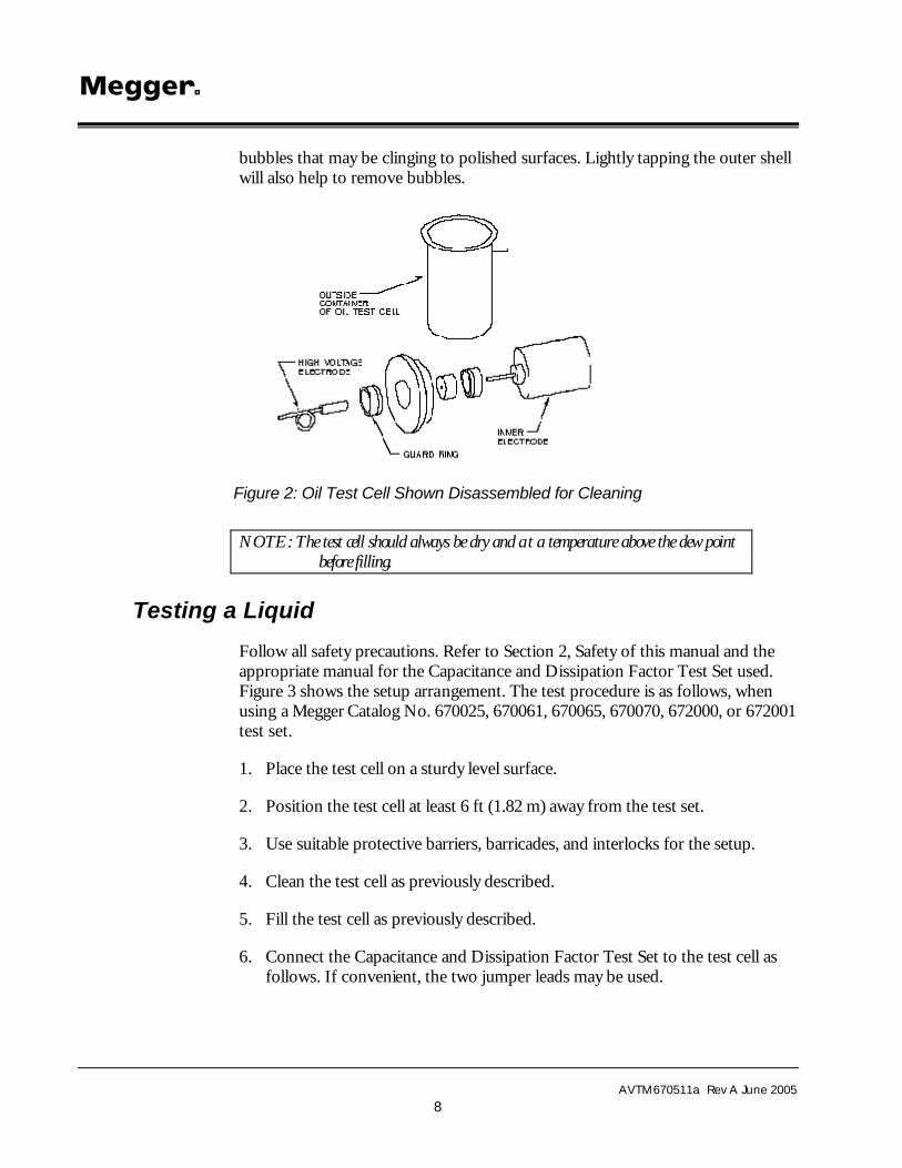
bubbles that may be clinging to polished surfaces. Lightly tapping the outer shell will also help to remove bubbles.
Figure 2: Oil Test Cell Shown Disassembled for Cleaning
NOTE: The test cell should always be dry and a t a temperature above the dew point before filling.
Testing a Liquid
Follow all safety precautions. Refer to Section 2, Safety of this manual and the appropriate manual for the Capacitance and Dissipation Factor Test Set used. Figure 3 shows the setup arrangement. The test procedure is as follows, when using a Megger Catalog No. 670025, 670061, 670065, 670070, 672000, or 672001 test set.
1. Place the test cell on a sturdy level surface.
2. Position the test cell at least 6 ft (1.82 m) away from the test set.
3. Use suitable protective barriers, barricades, and interlocks for the setup.
4. Clean the test cell as previously described.
5. Fill the test cell as previously described.
6. Connect the Capacitance and Dissipation Factor Test Set to the test cell as follows. If convenient, the two jumper leads may be used.

Operation
AVTM670511a Rev A June 2005
9
F WARNING
Maintain a clearance of approximately 1 in. (2.5 cm) between HV electrode and guard ring so that a flashover will not occur between these parts. Rigidly secure all test leads before making connections to te st cell to prevent capsizing of test cell while making a setup or during a measurement.
a. Connect the black HV lead of the test set to the HV electrode (pigtail terminal) of the test cell.
b. Connect the red LV lead of the test set to the pin terminal on the outside container of the test cell.
c. Connect the blue LV lead of the test set to the guard ring of the test cell.
7. The setup is now complete and ready for testing.
8. Set the TEST MODE selector switch of the test set to the UST3 position that measures to the red lead and grounds to the blue lead. If using the DELTA-2000 (Cat. No. 672001), choose “UST-MEASURE RED, GROUND BLUE” LOW VOLTAGE LEAD CONFIGURATION. A test could also be performed in the grounded mode using the GST position that guards the blue lead and grounds the red lead; however, this test would be more susceptible to stray and interference coupling.
9. Energize the test set and gradually increase the voltage to the desired test level. Keep in mind that the maximum voltage that can be applied to the test cell is:
10 kV rms maximum, filled with liquid
5 kV rms maximum, empty
G CAUTION A flashover may occur above the liquid level if there is an insufficient amount of liquid in the test cell.
10. Measure the capacitance and dissipation factor of the liquid.
11. De-energize the test set and apply a safety ground stick to the exposed high-voltage terminal to discharge the specimen and test set.
12. Then measure the temperature of the liquid sample while still in the test cell. Insert the glass thermometer in the hole in the top cover of the cell to make this measurement. The dissipation factor should be corrected to 20°C using the appropriate multipliers for the type liquid tested.

M
AVTM670511a Rev A June 2005
10
When samples of insulating liquids are tested, the specimen capacitance is used when determining the permittivity (dielectric constant) of the insulating liquids. The ratio of the test cell capacitance measured when filled with a liquid divided by the test cell capacitance measured when empty is the value of the permittivity of the liquid.
Checking Megger Capacitance & Dissipation Factor Test Sets
The Oil Test Cell and calibration standard resistor may also be used to perform a very rough check of the calibration of Megger Capacitance and Dissipation Factor Test Sets, including the DELTA-2000 Automated Insulation Power Factor Test Set, at a voltage of 5 kV or less. For a high accuracy check, the Megger Catalog No. 670500-1 Calibration Standard should be used.
The setup and test procedure is essentially identical to that used for testing a liquid. First, with the test cell clean and no liquid used, set up as shown in Figure 3. Do not use the mercury thermometer.
Figure 3: Test Setup to Measure the Dissipation Factor of a Liquid
F WARNING Maintain a clearance of approximately 1 in. (2.5 cm) between HV electrode and guard ring so that a flashover will not occur between these parts. Rigidly secure all test leads before making connections to test cell to prevent capsizing of test cell while making a setup or during a measurement.
Set the TEST MODE selector switch of the test set to the UST3 position that measures to the red lead and grounds to the blue lead. If using the DELTA-2000

Operation
AVTM670511a Rev A June 2005
11
(Cat. No. 672001), choose “UST - MEASURE RED, GROUND BLUE” LOW VOLTAGE LEAD CONFIGURATION. Then measure capacitance and dissipation factor in the usual manner using a test voltage of 5 kV or less. The test cell capacitance value in picofarads is listed on the nameplate of the test cell (nominally 55 pF). The test cell dissipation factor is nominally 0%DF.
A resistance unit, supplied with the test cell, provides two standard values of resistance (R), nominally 0.5 MΩ and 5 MΩ. Suitable-metal rods are provided for mounting the resistance unit on the center HV electrode of the test cell, and for connecting the black HV lead of the test set to the resistance unit.
Figure 4 shows the test setup to use the resistance standard and Oil Test Cell as a capacitance and dissipation factor standard. To mount the resistance unit on the test cell, connect one of the two-pin receptacles at one end of the resistance unit to HV electrode (pigtail) terminal of the test cell. Connect the HV lead of the test set to the single pigtail pin on the upper end of the resistance unit. The guard lead (blue LV lead) and UST lead (red LV lead) connections are made the same as when using the cell to test liquids. After measuring the capacitance and dissipation factor, shift the connection to the other pin receptacle of the resistance unit and again measure the capacitance and dissipation factor.
With a test cell capacitance of nominally 55 pF, the 0.5-MΩ resistor should measure in the range of 0.95 to 1.05 percent dissipation factor at 60 Hz. The 5-MΩ resistor should measure in the range of 9.5 to 10.5 percent dissipation factor at 60 Hz.
NOTE: For 50-Hz test voltage, the dissipation factors will be 5/6 of the values given above.

M
AVTM670511a Rev A June 2005
12
Figure 4: Test Setup as a Capacitance and Dissipation Factor Standard

AVTM670511a Rev A June 2005
13
5 Replaceable Parts List
Description Part No.
Test cell 9962
Calibration standard resistor 9961
Mercury-in-glass thermometer 210485
Jumper leads (two) 6046
Carrying case 9959
Center pigtail electrode of cell 4720

M
AVTM670511a Rev A June 2005
14
M