
OIL SPILLAGE DETECTOR APOLARM-C - Asahi Kasei
23
OIL SPILLAGE DETECTOR APOLARM-C Electrostatic Capacity Type INSTRUCTION MANUAL (Nov/2011) ASAHI KASEI TECHNOSYSTEM CO.,LTD. Rev. 1.0 Model CSR-3005E
Transcript of OIL SPILLAGE DETECTOR APOLARM-C - Asahi Kasei

OIL SPILLAGE DETECTOR
APOLARM-C
Electrostatic Capacity Type
INSTRUCTION MANUAL (Nov/2011)
ASAHI KASEI TECHNOSYSTEM CO.,LTD.
Rev. 1.0
Model CSR-3005E

1
OIL SPILLAGE DETECTOR
APOLARM-C INSTRUCTION MANUAL
CONTENTS page
1. Introduction 2 2. Main features 2 3. General specifications 3 4. Functional theory of "Apolarm-C" 4 5. Components 6
5-1. Detector Apolarm-C 6 5-2. Transducer 8 5-3. Dry pit attachment 11
6. Wiring and operation 12 6-1. Wiring 12 6-2. Operation 13 6-3. Oil leakage detection test 13
7. Installation of Apolarm-C 14 7-1. Determination of place for installation 14 7-2. Effective installation method 14 7-3. Cautions for installation work 17
8. How to Install Explosion-Proof Wiring 19 8-1. Selection of installation site 19 8-2. Wiring of intrinsically safe circuit 20 8-3. Applicable cable 20 8-4. How to discriminate external wiring of intrinsically safe circuit 20 8-5. Interconnection and branching 20 8-6. Panel wiring at non-hazardous area 21 8-7. Other wiring 21 8-8. Grounding 22
2
In the event of oil leaking out due to any accidental cause at an industrial lot where a large volume of oil is handled, the most important matter is to detect its occurrence without delay and to dispose of it quickly and adequately. "Apolarm-C" is intended to detect oil leakage that may take place at tank or pump yard in an area where oil is handled. This oil leakage detector has high reliability and excels in the capability of detecting high-viscous oils and can detect leaking oil even in such adverse surroundings where dust and whitewash tend to be produced.
◎ This is a detector produced with importance placed on pursuance for reliability.
* To improve strength against waves: This detector is shaped unsymmetrical between upper and lower parts from the draft line as border. This shape works to make this device stable against the up-and-down motion of waves. As the transducer is equipped with delay circuit, there is no fear of misinformation taking place.
* To prevent failure of detection: The underwater section and electrodes of floater are so structured as to be safe from whitewash-caused short circuit.
* Even if dust or grease is caught on the device surface, there is no fear of miss signal being sent out.
◎ Able to detect sticky oils as well. ◎ Permits optional selection of oil layer depth to detect.
*It is possible to detect leaked oil up to 50mm oil layer thickness by setting adequate electrodes, (optional supply)
◎ For both floater and cable, self-fire extinguishing type resin is used as material. This resin has high oil and chemicals resistance as well.
◎ Apolarm-C is a fail-safe type. In the event power failure to transducer or cable disconnection occurs, warning signal is given out.
◎ As this detector is made in an intrinsic safety type explosion-proofing structure, Apolarm-C can be installed at any hazardous place.
◎ It is easily observed the function in the field by means of actuating lamp on the Detector. ◎ It is easily fined out the difference of trouble such as oil alarm or system alarm by the two
lamps on the Transducer. ◎ The Transducer is provided with a delay timer of 1 ~1 0 (adjustable) second to prevent the
signal error caused by water wave and wind.
Introduction
Main features
3
Detectable objects : Petroleum items (crude oil, heavy oil, light oil, gasoline, lubricants, etc.), animal & vegetable, oil, olive oil, etc., organic solvents and others.
■ Detector (Apolarm-C) Model: CSR-3005E Sensitivity: 3 - 5 mm Objects to detect: Crude oil, gasoline, light oil, kerosene, heavy oil, lubricant, solvent, animal
& vegetable oils Structure: Water-proof structure Material: High impact resistance P. V. C. for Floater, SUS316 for Detector electrodes Weight: About 2.6 kg Cable: Synthetic rubber cable (flame-retardant, flexible, oil-resistant, weather-proof) 12
meters attached, 2-cores 0.75 mm each Maximum permissible cable length: 2 Km (2 mm cable) Ambient temperature : -20 ~ +60℃ ■ Transducer Model: AS-40E (built-in delay circuit, wire disconnection and short circuit alarm)
Delay timer: Approx. 1-10 second (adjustable)
Housing: See dimension figure Weight: About 800g
Power source: AC100/110V, 200/220V, 50/60Hz
Power consumption: Approx. 2VA
Output circuit : Contact output (type C × 2) oil alarm 1C & system alarm 1C
Contact capacity: AC250V, 4A DC30V, 4A
Ambient temperature : -10 ~ +50℃
Ambient humidity : ≦95% R. H.
Structure : Intrinsic safety type explosion-proof construction ⅡCT4 Short circuit current of input circuit: (max.) DC121. 6mA Open circuit voltage of input circuit: (max.) DC 14.3V Oil alarm: LED (green) light is on under normal operation System alarm: LED (red) light is off under normal operation
General specification
4
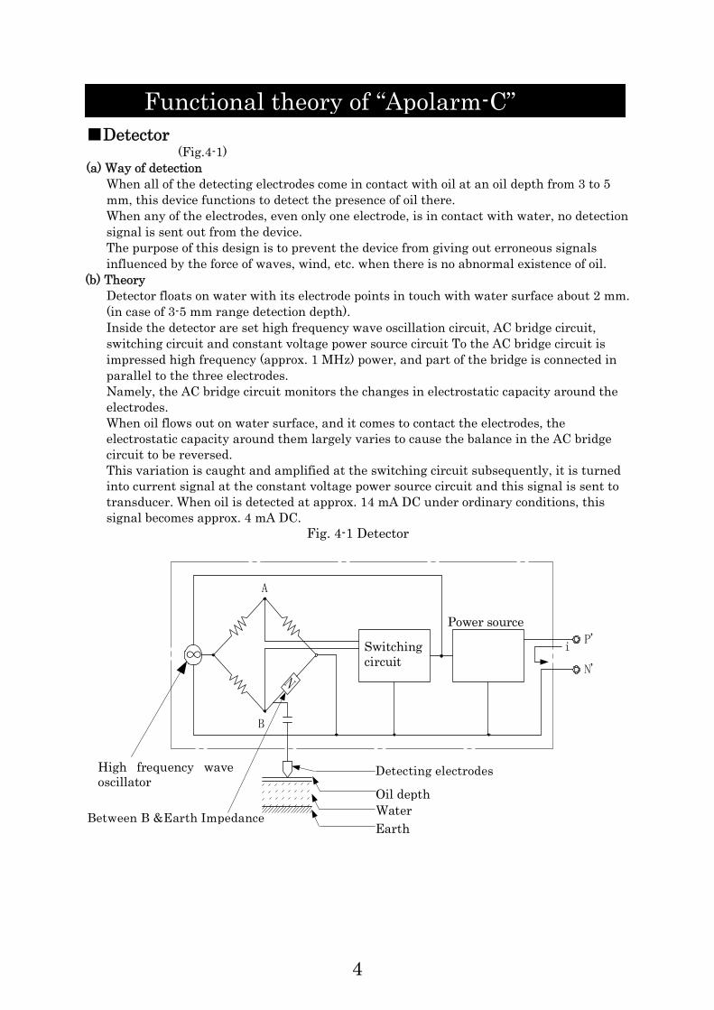
■Detector (Fig.4-1)
(a) Way of detection When all of the detecting electrodes come in contact with oil at an oil depth from 3 to 5 mm, this device functions to detect the presence of oil there. When any of the electrodes, even only one electrode, is in contact with water, no detection signal is sent out from the device. The purpose of this design is to prevent the device from giving out erroneous signals influenced by the force of waves, wind, etc. when there is no abnormal existence of oil.
(b) Theory Detector floats on water with its electrode points in touch with water surface about 2 mm. (in case of 3-5 mm range detection depth). Inside the detector are set high frequency wave oscillation circuit, AC bridge circuit, switching circuit and constant voltage power source circuit To the AC bridge circuit is impressed high frequency (approx. 1 MHz) power, and part of the bridge is connected in parallel to the three electrodes. Namely, the AC bridge circuit monitors the changes in electrostatic capacity around the electrodes. When oil flows out on water surface, and it comes to contact the electrodes, the electrostatic capacity around them largely varies to cause the balance in the AC bridge circuit to be reversed. This variation is caught and amplified at the switching circuit subsequently, it is turned into current signal at the constant voltage power source circuit and this signal is sent to transducer. When oil is detected at approx. 14 mA DC under ordinary conditions, this signal becomes approx. 4 mA DC.
Fig. 4-1 Detector
∞
N
B
A
i
P'
N'
Between B &Earth Impedance High frequency waveoscillator
Detecting electrodes
Oil depthWaterEarth
Switching circuit
Power source
Functional theory of “Apolarm-C”

5
■ Principle and structure (Fig.4-2)
Model CSR-3005E is an intrinsic safety type explosion-proof transducer. Floater has three electrodes, and high frequency current provided from its detector circuit checks the electrostatic capacity at the electrode section. When oil flows out onto water surface, the electrodes have to contact water through the oil layer, which causes their electrostatic capacity to vary largely. This variation in electrostatic capacity is detected and amplified in the detector circuit causing the transducer to work and put out contact signals.
①
②
③
④
⑩
⑨⑧⑦⑥⑤
P2
N2
E2
P1N1E1
B1 B2 OVC1 A1 C2 A2
PNE
100~110V
200~220VG
①Dry pit attachment: The detector electrode will be grounded when the water level is
getting low in the pit. ②Ball float: It prevents the detector from leaning because of the weight of a cable when
water level is unstable. ③APOLARM-C:CSR-3005E ④Apolarm guide: It prevents the detector from leaning and moving because of water
current and the level is unstable. ⑤Angle iron: It holds the Apolarm guide. ⑥Junction box: Use this box for the cable connection if the distance between detector and
transducer is more than 12 meters. ⑦Extension cable ⑧Transducer:AS-40E ⑨Transducer Box: Use this box if the environmental condition is not good for the
transducer. ) ⑩Power and signal cable
※ ①,②,④,⑤,⑥,⑦,⑨ and ⑩ are optional accessories.
Fig4-2
6
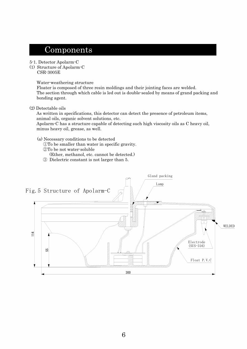
114
55
300
Float P.V.C
WELDED
Gland packing
Lamp
Fig.5 Structure of Apolarm-C
Electrode(SUS-316)
5-1. Detector Apolarm-C (1) Structure of Apolarm-C
CSR-3005E Water-weathering structure Floater is composed of three resin moldings and their jointing faces are welded. The section through which cable is led out is double-sealed by means of grand packing and bonding agent.
(2) Detectable oils As written in specifications, this detector can detect the presence of petroleum items, animal oils, organic solvent solutions, etc. Apolarm-C has a structure capable of detecting such high viscosity oils as C heavy oil, minus heavy oil, grease, as well. (a) Necessary conditions to be detected
①To be smaller than water in specific gravity. ②To be not water-soluble
(Ether, methanol, etc. cannot be detected.) ③ Dielectric constant is not larger than 5.
Components

7
Dielectric constants and specific gravity of main oils: Table 5-1
Petroleum items
Animal, vegetable and other oils Soybean oil Cotton-seed oil Caster oil Olive oil Linseed oil Turpentine oil
3.2 3.1 4.8 3.1 3.4 2.2
0.92 0.92 0.96 0.9
0.93 0.87
(b) Oil layer depth range detectable by Apolarm-C
Oils with fluidity can be detected by Apolarm-C when the oil layer reaches a 3 ~ 5 mm range thickness that is nearly constant regardless of the kind of oil. As to high viscosity oil, its presence is detected when the respective oil layers which came in contact with each of all the electrodes reach a 3 ~ 5 mm range thickness. The item-wise thickness of oil layer detected is as shown in the following table 5-2.
Items Dielectric constant Specific gravity Crude oil Naphtha Gasoline Jet engine fuel Kerosene Xylene Benzene Toluene A heavy oil B heavy oil C heavy oil Paraffin oil Styrene Machine oil Lubricant oil
2.2 - 2.5 2.0 2.0 1.7 2.0 2.3 2.3 2.3 2.0 2.2 2.3
2.2 - 4.7 2.4 2.1
2.3-3
0.7 0.76 0.83 0.78 0.87 0.87 0.87 0.85 0.89 0.93
0.85 or around 0.89 0.93
0.9 - 0.93
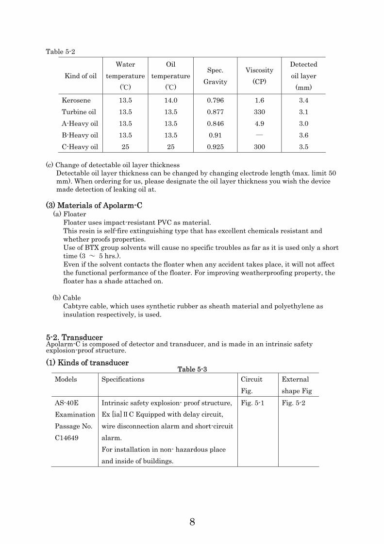
8
Table 5-2
Kind of oil Water
temperature (℃)
Oil temperature
(℃)
Spec. Gravity
Viscosity (CP)
Detected oil layer
(mm)
Kerosene Turbine oil A-Heavy oil B-Heavy oil C-Heavy oil
13.5 13.5 13.5 13.5 25
14.0 13.5 13.5 13.5 25
0.796 0.877 0.846 0.91 0.925
1.6 330 4.9 ―
300
3.4 3.1 3.0 3.6 3.5
(c) Change of detectable oil layer thickness
Detectable oil layer thickness can be changed by changing electrode length (max. limit 50 mm). When ordering for us, please designate the oil layer thickness you wish the device made detection of leaking oil at.
(3) Materials of Apolarm-C (a) Floater
Floater uses impact-resistant PVC as material. This resin is self-fire extinguishing type that has excellent chemicals resistant and whether proofs properties. Use of BTX group solvents will cause no specific troubles as far as it is used only a short time (3 ~ 5 hrs.). Even if the solvent contacts the floater when any accident takes place, it will not affect the functional performance of the floater. For improving weatherproofing property, the floater has a shade attached on.
(b) Cable Cabtyre cable, which uses synthetic rubber as sheath material and polyethylene as insulation respectively, is used.
5-2. Transducer Apolarm-C is composed of detector and transducer, and is made in an intrinsic safety explosion-proof structure. (1) Kinds of transducer
Table 5-3 Models Specifications Circuit
Fig. External shape Fig
AS-40E Examination Passage No. C14649
Intrinsic safety explosion- proof structure, Ex [ia]ⅡC Equipped with delay circuit, wire disconnection alarm and short-circuit alarm. For installation in non- hazardous place and inside of buildings.
Fig. 5-1 Fig. 5-2

9
(2) Restriction on wiring length The cable that connects detector and transducer works as a kind of condenser and coil. Electric energy may accumulate in this cable and such energy may work to impair the intrinsic safety of the device. For this reason, the maximum wiring cable length is restricted under the explosion-proofing principles.
Table 5-4
Fig. 5-1 AS-40E
RY1
RY2
LD2 RY1 RY2LD1
VR
P
N
E
ZD
F
(AS-30)
◎ Explosion-proof structure
Intrinsic safety explosion-proof structure (explosion-proof mark Ex [ia] ⅡCT4) ◎ Rating
Intrinsic safety circuit DC16mA, 12V Short-circuit current DC12l.6mA (max) Open-circuit voltage DC14.3V (max)
Non-intrinsic safety circuit 1. Input power source voltage
AC 100~110V±10% 50/60Hz AC 200~220V±10% 50/60HZ
2. Contact capacity AC 250 V, 4A DC30V, 4A 3. Control contact circuit 2C
(Oil leakage, system trouble) 4. Ambient temperature and humidity for working -10 ~ +50℃ ≦ 95%RH 5. Pilot lamp Green: oil leakage
Red: system trouble
Models Explosion-proofing
grade Use conditions
Wiring length for reference; 600V CVV
2mm core (2) AS-40E Ex [ia] ⅡCT4 Allowable inductance
L: smaller than2mH Allowable capacitance
C : smaller than 0.5μF
For safety's sake, it is desirable to restrict the length within2 km.
10
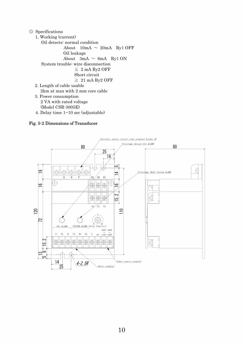
◎ Specifications 1. Working (current)
Oil detects: normal condition About 10mA ~ 20mA Ry1 OFF Oil leakage About 3mA ~ 8mA Ry1 ON
System trouble: wire disconnection ≦ 2 mA Ry2 OFF Short circuit ≧ 21 mA Ry2 OFF
2. Length of cable usable 2km at max with 2 mm core cable
3. Power consumption 2 VA with rated voltage (Model CSR-3005E)
4. Delay time 1~10 sec (adjustable)
Fig. 5-2 Dimensions of Transducer
N2 P2
C1 B1 A1 C2 B2 A2 0V 110V~
100V
220V
200V~
E1
E2
N1 P1E N P
5
0
10SYSTEM ALARMOIL ALARM DeIay Time(sec)
58
15.2
1916
7213
2514
80
110
514
1615
.2
1425
80
120
4-2.5ROuter terminal
Power source terminal
Intrinsic safety circuit side terminal holder 3P
Pilotlamp (Green) Oil ALARM
Pilotlamp (Red) System ALARM
G

11
5-3. Dry pit attachment In case there is no water ordinarily or there is a fear of water being emptied, dry pit attachment is used. When the water level drops, the electrode points come in contact with the contact plate of the attachment and cease to further go down. Therefore, the electrodes are earthed as are when floating on water. (1) For visual figure, see Fig. 5-3. Fig. 5-3 External figure of dry pit attachment Model TC-SE
① Set screw (4 mm) ② Pipe. 10ASUS 304
Sch #80 (JIS) ③ 265-1.6t SUS 304 plate
Note 1) Weight of dry pit attachment 1.5 kg Note 2) Supporter rods should be prepared on the side of client. The inner diameter of pipe for
leg section is 10.9 mmφ. As supporter rod, pipe with an outer diameter of 10.5mmφor 10 mmφis recommendable.
1.6t
Set screw(4mm)
92
12
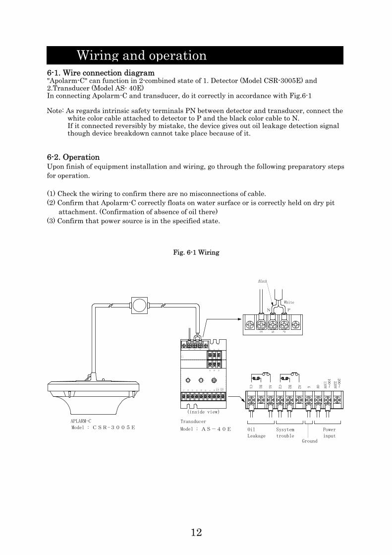
6-1. Wire connection diagram "Apolarm-C" can function in 2-combined state of 1. Detector (Model CSR-3005E) and 2.Transducer (Model AS- 40E) In connecting Apolarm-C and transducer, do it correctly in accordance with Fig.6-1 Note: As regards intrinsic safety terminals PN between detector and transducer, connect the
white color cable attached to detector to P and the black color cable to N. If it connected reversibly by mistake, the device gives out oil leakage detection signal though device breakdown cannot take place because of it.
6-2. Operation Upon finish of equipment installation and wiring, go through the following preparatory steps for operation. (1) Check the wiring to confirm there are no misconnections of cable. (2) Confirm that Apolarm-C correctly floats on water surface or is correctly held on dry pit
attachment. (Confirmation of absence of oil there) (3) Confirm that power source is in the specified state.
Fig. 6-1 Wiring
Wiring and operation
G
220V
200~
110V
100~
E N P
A2C2A1C1 OVB2B1
E1 N1 P1
E2 N2 P2
110V100~
220V200~OVA2C2A1C1 B2B1
N P
PNE
APLARM-C
White
Black
(inside view)
Transducer
OilLeakage
Sysytemtrouble
Powerinput
Ground
G
G
Model : CSR-3005E Model : AS-40E

13
(4) Operation Table 6-1
Normal Oil detect
System trouble
(APOLARM Cable
short or open)
APOLARM-C
Model
CSR-3005E
Pilot Lamp
(Green) ON OFF OFF
Pilot Lamp
(Green) ON OFF ON
Lamp
Transducer
Model AS-40E Pilot Lamp
(Red) OFF OFF ON
Oil ALARM
Contact A1-C1 OPEN CLOSE OPEN
Oil ALARM
Contact B1-C1 CLOSE OPEN CLOSE
System ALARM
Contact A2-C2 CLOSE CLOSE OPEN
Contact Transducer
Model AS-40E
System ALARM
Contact B2-C2 OPEN OPEN CLOSE
6-3. Oil leakage detection test Detecting sensitivity of Apolarm-C is tested along the following steps. (1) Prepare a test-use water tank and put water in it.
Put Apolarm-C on the water surface. In case of metallic water tank, it should be larger 400 mmφand in case of plastic water tank, it should be larger than 350 mmφ. Earth the water in tank.
(2) Make correct wiring for Apolarm-C and its transducer. (See Fig.6-1) (3) Hold the cable of Apolarm-C at right above the detector. (Standard length of cable for this
holding is 1 m.) (4) Put ON the power source of transducer. (Pilot lamp green lights) (5) Gently send oil falling on the water little by little from a comer the tank.
When the pilot lamp of transducer goes out, stop the oil sending. Confirm the amount of oil fed in the tank.
(6) The oil layer thickness detectable is sought by the following formula.
H: Oil layer thickness (cm) V: Amount of oil fed in tank (cm) A: Surface area of water in tank (cm) a: Cross section area of Apolarm-C on its draft line level
VH = A - a
14
7-1. Determination of place for installation The thickness of oil layer produced by leaked oil gets the thinner the wider the dispersed area of the oil. Therefore, it is important how to gather the leaked oil in a limited area. Gathering of oil in a small area makes easier the work of oil recovering, which leads to thwarting the mishap from expanding further. This eventually helps increase the reliability of the detector. Users are requested to understand enough the above fact and install Apolarm-C correctly at an adequate place. For example, such places as listed below are recommendable as places where to install Apolarm-C. a) Oil pit inside of the oil bank. b) Oil pit in pump yard.
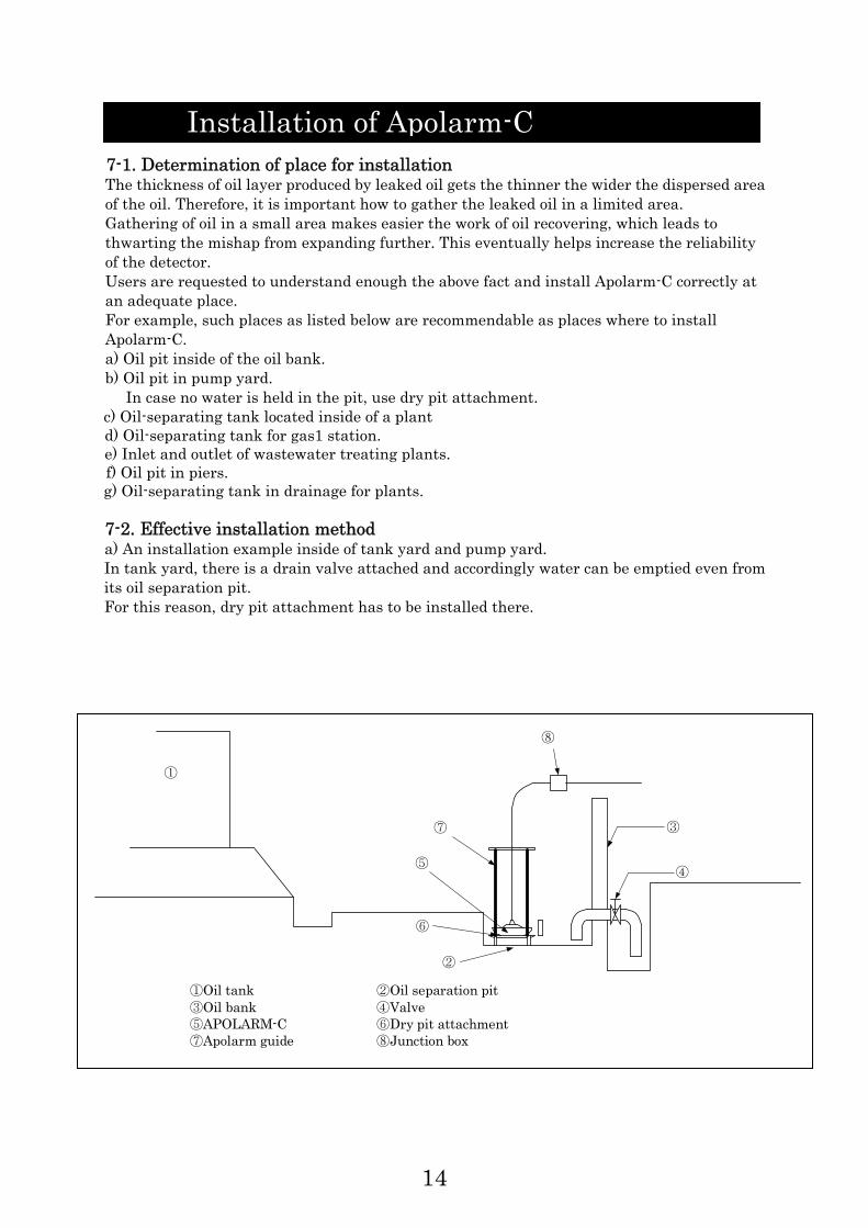
In case no water is held in the pit, use dry pit attachment. c) Oil-separating tank located inside of a plant d) Oil-separating tank for gas1 station. e) Inlet and outlet of wastewater treating plants. f) Oil pit in piers. g) Oil-separating tank in drainage for plants. 7-2. Effective installation method a) An installation example inside of tank yard and pump yard. In tank yard, there is a drain valve attached and accordingly water can be emptied even from its oil separation pit. For this reason, dry pit attachment has to be installed there.
①
②
③ ④ ⑤
⑥
⑦
⑧
①Oil tank ②Oil separation pit ③Oil bank ④Valve ⑤APOLARM-C ⑥Dry pit attachment ⑦Apolarm guide ⑧Junction box
Installation of Apolarm-C

15
b) An installation example in oil separation pit
① As generally the oil separation pit is filled with water.
Therefore, it is unnecessary to set dry pit attachment there. When the oil pit is emptied, warning signal is send forth.
② If there is any obstacle in oil separation pit or if there is a fear of something getting near
the waste water inlet, set there the Apolarm guide. c) An installation example of Apolarm guide.
Junction box
APOLARM-C
Oil separation pit
■Oil separation pit
Dry pit attachment Apolam guide
■Dry pit
Guide
Ball float
■ In case variation of w ater level is large

16
d) An installation example in large capacity pit (excessively large pit). In case of large capacities pit that usually holds water in it; prepare a detecting-use separator as shown in the bellow figure. The appropriate length & width measurements of separator is ordinarily 400 ~ 600 mm.
Separator
Separator
Apolarm

17
7-3. Cautions for installation work (1) Relation between oil layer thickness detectable and out flowing amount of oil
The amount the leaked-out oil is required to reach after oil begins to leak out for the detector to start giving out oil detection signal is indicated by the following formula:
Amount of leaked-out oil
= (oil layer thickness detectable by detector) × (surface area of pit)
Particularly when the detector is installed in an oil-water separation tank or wastewater pit with a large surface area, it is required to divide the tank room with oil separator, or to take a similar measure. Such care eventually insures better sensing effect of the detector.
(2) High viscosity oil
With its out-protruded electrodes, Apolarm-C readily detects presence of high viscosity oil. Even if the oil has got greasy, it can be detected if the oil gathers around the detector. Therefore, it is unnecessary to take a specific measure to detect high viscosity oil.
(3) Freezing Even if the inside of pit has completely got in a frozen state, this freezing does not cause Apolarm-C to be damaged. However, in such a state, the detector cannot sense the presence of oil until the water is not frozen. Therefore, the pit must be kept from freezing inside. To mention precisely, the measure to take for prevention of freezing should differ according to the place Apolarm is installed. But a typical method to keep the pit safe from freezing is providing a heating source inside of the pit. In this case, give consideration not to raise the temperature of water over 60℃.
(4) Floating matters Apolarm-C is perfectly free from the adverse effects of dust floating on water surface, organisms, slime, duckweed, scale, etc. contained in water. However, a large volume of dust can hinder in-flowing oil. Therefore, dust has to be removed from water surface periodically.
(5) Wave and flow rate of water
Apolarm-C is unsymmetrical between its upper section and lower section, which works to quickly stabilize its posture against up-and-down motion of waves. As long as any of the three electrodes is in touch with water, Apolarm continues to give out normal signal. While the probability of all of three electrodes going out of touch with water surface at the same time is very small, the transducer is provided with a delay circuit of approximately 1 ~1 0 second. Because of these factors, users need no fear signaling errors attributable to water waves. As to water flow rate, keep it within 0.2m/sec. on the flowing water surface. If the flow rate is larger than this limit, the oil layer could not maintain thickness of 3~ 5mm or more. In any case, don't forget providing guide rods.

18
(6) Correlation between thickness of detected oil layer and cable load
The weight of cable is 100g/m. Floater is so adjusted as to detect a 4mm thick layer of kerosine under a load of 1 m long cable. Detected oil layer thickness is in proportion to the sinking depth of electrodes. Accordingly, with increased load of cable given on floater, the detected oil layer depty increases. In case floater swings sideways, these swings likewise influence the oil layer depty at which the presence of oil is detected. Therefore, where water waves regularly cause large lateral swings of floater; some appropriate measure to offset such influence has to be taken. As such measure, the following two" " methods are conceivable: 1) To make smaller the head of inflowing wastewater or to scatter the in-flowing course of
the water. 2) To make smaller the waves at the location of detector by placing their wave-breaking
plate, net, chamber, etc.
(7) Noise proof structure A high frequency (around 1 MHz) is used inside this detector, which, therefore, may issue false signal if a transceiver or other high frequency source is nearby. Though this new Apolarm (CSR-3005E) has enhanced its immunity against external interference, do not use, as much as possible, such a transceiver, etc. near the Apolarm. If it is not allowed to keep a sufficient distance from the noise source, design the installation rack and cables of the Apolarm-C into a shielded structure.
19
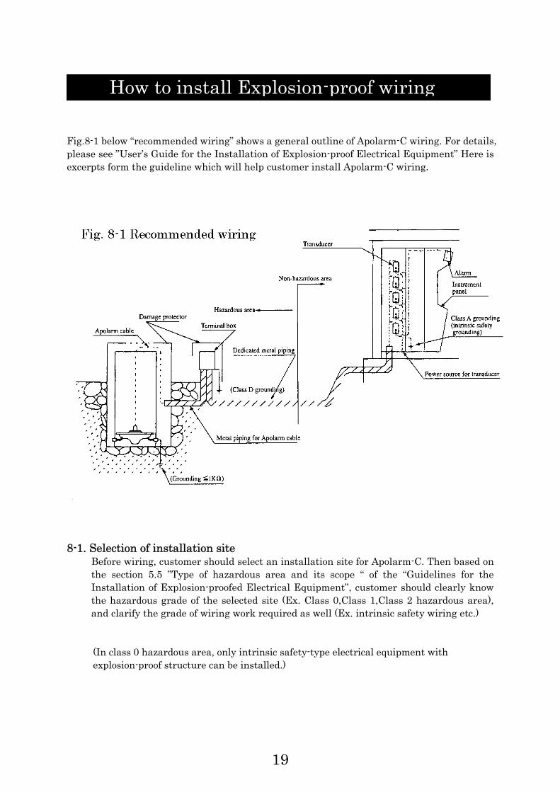
Fig.8-1 below “recommended wiring” shows a general outline of Apolarm-C wiring. For details,please see ”User’s Guide for the Installation of Explosion-proof Electrical Equipment” Here is excerpts form the guideline which will help customer install Apolarm-C wiring.
8-1. Selection of installation site
Before wiring, customer should select an installation site for Apolarm-C. Then based on the section 5.5 ”Type of hazardous area and its scope “ of the “Guidelines for the Installation of Explosion-proofed Electrical Equipment”, customer should clearly know the hazardous grade of the selected site (Ex. Class 0,Class 1,Class 2 hazardous area), and clarify the grade of wiring work required as well (Ex. intrinsic safety wiring etc.)
(In class 0 hazardous area, only intrinsic safety-type electrical equipment with explosion-proof structure can be installed.)
How to install Explosion-proof wiring
20
8-2. Wiring of intrinsically safe circuit (Guide for the Installation of Explosion-proofed Electrical Equipment 9.6)
(1) When Aploarm-C cable needs to be installed near other cables, Apolarm cable must
be wired independently by using metal pipe or metal duct in order to prevent power cross, static induction and electromagnetic induction. If Apolarm-C’s intrinsically safe circuit needs to be installed in a same duct with other intrinsically safe circuit, shielded cables must be used and properly grounded.
(2) When there is no circuit exist other then Apolarm-C’s intrinsically safe circuit and
there is no potential factors (Ex. power cross and induction) to lower explosion-proof performance, above instruction shall be omitted.
8-3 Applicable cable
(Guide for the Installation of Explosion-proofed Electrical Equipment 9.6.6.4)
For intrinsically safe circuit and its related circuit, 600V vinyl cable (JIS C 337) VV-0.5mm or cable with the same level or higher insulation performance, nominal cross-sectional area, and strength can be applicable.
8-4. How to discriminate external wiring of intrinsically safe circuit
(Guide for the Installation of Explosion-proofed Electrical Equipment 9.6.6.6)
External wiring connected to the intrinsically safe equipment should be covered with light blue insulating film or tape at the cable terminal so that everyone can easily distinguish intrinsically safe circuit from other circuit.
8-5. Interconnection and branching
(1) NO cables in the intrinsically safe circuit must be interconnected or branched in Class
0 hazardous area. Only connection to the intrinsically safe equipment is allowed.
(2) When an intrinsically safe circuit needs to be interconnected or branched in a junction box, the cable must not coexist with a terminal area of non-intrinsically safe circuit. However, when a separator is used in a hazardous area to separate intrinsically safe circuit from other circuit in order to avoid power cross, and when the junction box has a clear storage category for intrinsically safe circuit, the above instruction shall be omitted.
(3) When connecting and branching intrinsically safe circuit, be sure to connect all cables
securely so that it will not cause power cross with other circuit.
(Guide for the installation of Explosion-proofed Electrical Equipment 9.6.6.2)
21
8-6. Panel wiring at non-hazardous area (Guide for the Installation of Explosion-proofed Electrical Equipment 9.6.6.7)
In the event of wiring intrinsically safe circuit inside the instrument panel in non-hazardous area, be sure to follow the instructions below. In general, the panel must have a relay box for external wiring of this relay box should be installed inside the panel.
(1) When both intrinsically safe equipment and other electrical equipment need to be
mounted in a same panel, the position of these equipments, relay box and wiring method must be well arranged so that it will not cause power cross and induction.
(2) In general, the panel must have a relay box so that cables for intrinsically safe circuit
and other circuit can be properly relayed inside the panel. The energized part must be protected by a cover so that it may not cause power cross with non-intrinsically safe circuit.
In addition, in order to prevent miss-wiring, the relay box should use something light blue for intrinsically safe circuit so that everyone can find it easily and quickly.
8-7. Other wiring
See the “Guide for the Installation of Explosion-proofed Electrical Equipment 9.6.” 8-8. Grounding
(1)Transducer E terminal of the intrinsically safe terminal P, N, E and G terminal of power source terminal G, 0V, 100-110V, 200-220V are not connected inside the transducer.
[Purpose of each E terminal]
E terminal of the intrinsically safe side P, N, E Purpose: To maintain intrinsically safe explosion-proof structure
…..Class A or higher level grounding is required.
G terminal of power source side G, 0V, 100V, 200-220V Purpose: To prevent electrical shock (in accordance with the Technical
Standard for Electrical Equipment) ……Transducer’s G terminal is connected to the case. Terminal
should be grounded as required.
Grounding terminal G of safety barrier side ……The terminal is connected to the case. Terminal should be
grounded as required.
22
(2) Dry pit attachment Dry pit attachment need to be grounded. However, regular installation
automatically ground the equipment so no additional grounding is required by the customer. But if oil tank and oil separation pit is made of resin whose grounding resistance is extremely high, dry pit attachment needs additional grounding because it may sometimes cause misinformation. (when the grounding resistance is ≦1Ω)
!Warning ***Caution for wiring intrinsically safe circuit*** Intrinsically safe circuit covers from Apolarm-C through transducer’s input. For the wiring of this circuit, be sure to follow the standards described in the “User’s Guide for the Installation of Explosion-proofed Electrical Equipment”. Do not use any transducer other than AS-40E with Apolarm-C (CSR-3005E).
*If Apolarm-C and transducer (AS-40E) do not have same registration number of the Type Certificate; please contact our dealership or ASAHI KASEI TECHNOSYSTEM CO., LTD.


![AKD4254-A Rev.2 English Manual - Asahi Kasei Microdevices · ASAHI KASEI [AKD4254-A] EVALUATION BOARD MANUAL Operation sequence 1) Set up power supply lines. Name of jack Color of](https://static.fdocuments.in/doc/165x107/5b1526cd7f8b9a467c8de8e8/akd4254-a-rev2-english-manual-asahi-kasei-microdevices-asahi-kasei-akd4254-a.jpg)
