oil-2007-2s-9
11
Oil Shale, 2007, Vol. 24, No. 2 Special ISSN 0208-189X pp. 285–295 © 2007 Estonian Academy Publishers EXCITATION SYSTEM MODELS OF GENERATORS OF BALTI AND EESTI POWER PLANTS R. ATTIKAS * , H.TAMMOJA Department of Electrical Power Engineering Tallinn University of Technology, 5 Ehitajate Rd., 19086 Tallinn, Estonia This paper describes the requirements for the generator’s excitation system. Different parts of the excitation system are also presented. Two totally different types of excitation systems are installed in generators of both Eesti and Balti power plants. The one – fast static excitation system UNITROL5000 produced by ABB – was installed in 2005. The other is a rather slow excitation system – high-frequency AC machine – produced in Russia in the middle of the 70s. The paper presents main structures of those excitation systems and their control systems and also proposes models of control systems for dynamic calculations of those systems. Introduction Balti and Eesti power plants are two world’s biggest power plants working on oil shale. With generation capacities of 765 MW and 1615 MW those plants produce approximately 95% of Estonia’s power consumption. Renovation of one power unit at both power plant was completed in 2005. During the renovation new boilers were built, turbines and generators were renovated, and control systems of the power units were also renewed. The total capacity of the new units is 430 MW. Excitation systems of generators in Balti and Eesti power plants were chosen for investigation because their work has the biggest impact on dynamic stability of the Estonian grid. Two totally different types of excita- tion systems are simultaneously used at Eesti and Balti power plants. A rather slow high-frequency AC machine excitation system (P-system) produced in Russia in the middle of the 70s is in use, and a fast static excitation system (PD-system) UNITROL5000 produced by ABB was installed in 2005. As the two excitation systems are used in both power plants, the models for dynamic calculations proposed in this paper can be * Corresponding author: e-mail [email protected]
-
Upload
mindphaser -
Category
Documents
-
view
219 -
download
0
Transcript of oil-2007-2s-9
8/18/2019 oil-2007-2s-9
http://slidepdf.com/reader/full/oil-2007-2s-9 1/11
Oil Shale, 2007, Vol. 24, No. 2 Special ISSN 0208-189Xpp. 285–295 © 2007 Estonian Academy Publishers
EXCITATION SYSTEM MODELS OF GENERATORS
OF BALTI AND EESTI POWER PLANTS
R. ATTIKAS*, H.TAMMOJA
Department of Electrical Power EngineeringTallinn University of Technology,5 Ehitajate Rd., 19086 Tallinn, Estonia
This paper describes the requirements for the generator’s excitation system.
Different parts of the excitation system are also presented. Two totallydifferent types of excitation systems are installed in generators of both Eestiand Balti power plants. The one – fast static excitation systemUNITROL5000 produced by ABB – was installed in 2005. The other is arather slow excitation system – high-frequency AC machine – produced in Russia in the middle of the 70s. The paper presents main structures of thoseexcitation systems and their control systems and also proposes models of
control systems for dynamic calculations of those systems.
Introduction
Balti and Eesti power plants are two world’s biggest power plants working
on oil shale. With generation capacities of 765 MW and 1615 MW those
plants produce approximately 95% of Estonia’s power consumption.
Renovation of one power unit at both power plant was completed in 2005.
During the renovation new boilers were built, turbines and generators were
renovated, and control systems of the power units were also renewed. The
total capacity of the new units is 430 MW.
Excitation systems of generators in Balti and Eesti power plants were
chosen for investigation because their work has the biggest impact on
dynamic stability of the Estonian grid. Two totally different types of excita-tion systems are simultaneously used at Eesti and Balti power plants. A
rather slow high-frequency AC machine excitation system (P-system)
produced in Russia in the middle of the 70s is in use, and a fast static
excitation system (PD-system) UNITROL5000 produced by ABB was
installed in 2005. As the two excitation systems are used in both power
plants, the models for dynamic calculations proposed in this paper can be
* Corresponding author: e-mail [email protected]

8/18/2019 oil-2007-2s-9
http://slidepdf.com/reader/full/oil-2007-2s-9 2/11
R. Attikas, H.Tammoja286
used in both power plants as well. Both types of excitation systems have
been investigated. The static excitation system UNITROL5000 produced byABB and used in one 253-MVA generator of Balti Power Plant and in one
253-MVA generator of Eesti Power Plant was studied first followed by
studies on the Russian type of high-frequency AC machine excitation system
which is used in three 200-MVA generators of Balti Power Plant and in
seven 200-MVA generators of Eesti Power Plant.
The basic function of an excitation system is to provide direct current to
the field winding of the synchronous machine. The protective functions
ensure that capability limits of the synchronous machine, excitation system,
and other equipment are not exceeded.
The excitation system also performs control and protective functions
important for satisfactory performance of the power system by controlling
the field voltage and by that the field current. The control functions include
the control over voltage and reactive power flow, and the enhancement of
system stability.
Requirements for reliable performance of the excitation system have to
be determined considering both the synchronous generator and the power
system. The basic requirement is that the excitation system supplies and
automatically adjusts field current of the synchronous generator to maintain
terminal voltage as the output varies within the continuous capability of
generator’s U-curves. Margins for temperature variations, component
failures, emergency overrating, etc. must be factored in when the steady-
state power rating is determined. Usually, the exciter’s rating varies from 2.0
to 3.5 kW/MVA generator’s rating [2].The excitation system must also be able to respond to transient dis-
turbances by field forcing consistent with instantaneous and short-term
capabilities of the generator. Considering this, there are many factors that
limit generator capabilities: rotor insulation failure caused by high field
voltage, rotor heating caused by high field current, stator heating due to high
armature current loading, core end heating during under-excited operation,
and heating caused by high excess flux (volts/Hz). There are time-dependent
characteristics of thermal limits, and the short-term overload capability of
generators that may be measured from 15 up to 60 seconds. To secure the
best use of the excitation system, it should be able to meet the system
requirements by taking full advantage of short-term capabilities of the
generators without surpassing their limits.As for the power system, effective control of voltage and enhancement of
system stability should be supported by the excitation system. It should be
able to respond rapidly to a disturbance improving transient stability
modulating the generator field to improve small-signal stability. In addition
to the error signal of terminal voltage, modern excitation systems are using
auxiliary stabilizing signals (power system stabilizer) to control the field
voltage to damp system oscillations. Modern excitation systems with high
ceiling voltages are capable of providing practically instant response.

8/18/2019 oil-2007-2s-9
http://slidepdf.com/reader/full/oil-2007-2s-9 3/11
Excitation System Models of Generators of Balti and Eesti Power Plants 287
A substantial improvement of dynamic performance of the overall system
can be achieved by combination of high field-forcing capability with the useof auxiliary stabilizing signals.
Exciter. It provides dc power to the field winding of the synchronous
machine. Exciter can be either an AC machine, DC machine, or it is fed from
generator’s terminal switchgear through converter.
Regulator. It processes and amplifies input control signals to a level and
form appropriate for control of the exciter. This includes both regulating and
stabilizing the functions of the excitation system (rate feedback or lead-lag
compensation).
Protective circuits and limiters. They include a wide range of control and
protective functions to guarantee that the capability limits of exciters and
synchronous generator are not exceeded. Limitation of maximum excitation,
terminal voltage, field-current and underexcitation, regulation and protection
of volts-per-hertz ratio are some of the principal functions. These circuits are
usually distinct ones, and their output signals may be applied to the excita-
tion system at different locations as a summing input or a gated input. In
Fig. 1 they are grouped and shown as a single block for better consideration.
Load compensation and terminal voltage transducer. Terminal voltage
transducer senses generator’s terminal voltage, rectifies and filters it to dc
quantity, and compares it with a reference which represents the desired
terminal voltage. If it is desired to hold constant voltage at some point
electrically remote from the generator’s terminal, load (or line-drop, or
reactive) compensation may be also provided. Load compensation function
is optional, and at Eesti and Balti power plants it is used in UNITROL5000, but it is not used in the Russian high-frequency AC machine excitation
system.
Fig. 1. Functional block diagram of the control system of a synchronousgenerator’s excitation.

8/18/2019 oil-2007-2s-9
http://slidepdf.com/reader/full/oil-2007-2s-9 4/11
R. Attikas, H.Tammoja288
Power system stabilizer (PSS). Its function is optional as well. It is not
used in the Russian high-frequency AC machine excitation system, but it isused in UNITROL5000. PSS is used to add modulation signal to the
regulator to damp power system oscillations. Some commonly used input
signals are rotor speed deviation, electrical or accelerating power and
frequency deviation.
Methodology
The excitation system should be considered from the aspect of classical
control methodology. A classical control methodology is based on feedback
and error-driven control.
Simple systems are usually one-dimensional that means one input signal
and one output signal. In that case the dependence of controlled object state
on output is easily describable by a relatively simple function hence these
systems could be successfully controlled by the output signal. The aim of
regulation is automatic stabilization of the output, changing it by a given or
by some unknown (stochastic, fuzzy) principle. These systems are called
stabilizing and control systems.
Simple systems can be controlled by two principles. The first principle is
that regulation action is dependent on regulation error, this action uses feed-
back for regulation, hence it is called feedback control. The second principle
is that the regulation action is made in a way that compensates disturbance
influences. Usually a combination of both principles is used, and in this caseregulation action is a function of regulation error and disturbance compensa-
tion. Disturbance compensation principle is distinguishable from feedback
principle only with some simplification, because generally measured dis-
turbances can also be viewed as output of the controlled object, and feedback
can also be used for regulation.
Controlled object is always of a specific structure. Technical and techno-
logical regulation objects are the objects consisting of controlled operation
and measurement equipment. Measuring equipments give information about
working of the controlled object. Regulator compares design state of the
object with its actual state and makes regulation actions.
In the case of the excitation system, the generator is the controlled object,
and controlled operation is the control of generator’s acceleration. Anexcitation system uses both above-mentioned principles: regulation error and
disturbance compensation. Representation of excitation systems by automa-
tion block diagrams is necessary for making accurate dynamic calculations
and also in the case if the software model library used at calculations does
not contain the required model. Software programs of dynamic calculations
such as PSSE and PSCAD used at Estonian TSO and at Tallinn University of
Technology do not contain the models of equipment produced in Russia.

8/18/2019 oil-2007-2s-9
http://slidepdf.com/reader/full/oil-2007-2s-9 5/11
Excitation System Models of Generators of Balti and Eesti Power Plants 289
PSSE and PSCAD offer the possibility to model excitation system by
automation blocks.
Models of excitation systems
Static excitation system UNITROL5000, as mentioned above, is used in one
253-MVA generator of Balti Power Plant and in one 253-MVA machine of
Eesti Power Plant. According to the information from ABB [9], static
excitation system UNITROL5000 has the following functions:
• Voltage regulator with PID filter (AUTO operating mode);
• Field current regulator with PI filter (MAN operating mode);
•
Reactive load and/or active load droop/compensation;• Limiters for:
o Maximum and minimum field current
o Maximum stator current (lead/lag)
o P/Q under excitation
o Voltage-per-hertz characteristics.
• Power factor/reactive load regulation;
• Power system stabilizer (PSS)
o conventional in accordance with IEEE-PSS2A
o Adaptive power system stabilizer
o Multiband power system stabilizer.
All components in these systems are static. The excitation power is
supplied through a transformer from the station auxiliary bus, and it isregulated by a controlled rectifier. This type of the excitation system is also
commonly known as a bus-fed or transformer-fed static system (see Fig. 2).
Fig. 2. Scheme of the static excitation system.
GS
DC regulator
AC regulator
Exciter
transformer
Controlled
rectifier
Slip rings
Main generator
Field
DC ref.
AC ref.
Aux. inputs
CT
VT
8/18/2019 oil-2007-2s-9
http://slidepdf.com/reader/full/oil-2007-2s-9 6/11
R. Attikas, H.Tammoja290
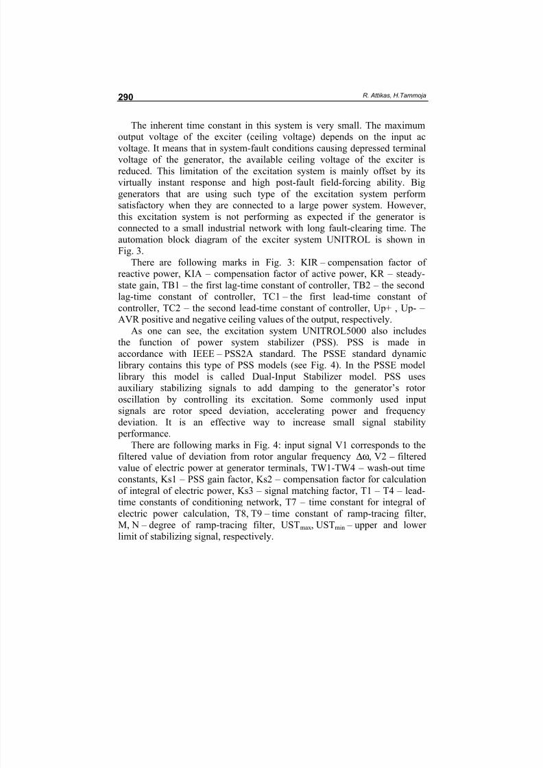
The inherent time constant in this system is very small. The maximum
output voltage of the exciter (ceiling voltage) depends on the input acvoltage. It means that in system-fault conditions causing depressed terminal
voltage of the generator, the available ceiling voltage of the exciter is
reduced. This limitation of the excitation system is mainly offset by its
virtually instant response and high post-fault field-forcing ability. Big
generators that are using such type of the excitation system perform
satisfactory when they are connected to a large power system. However,
this excitation system is not performing as expected if the generator is
connected to a small industrial network with long fault-clearing time. The
automation block diagram of the exciter system UNITROL is shown in
Fig. 3.
There are following marks in Fig. 3: KIR – compensation factor of
reactive power, KIA – compensation factor of active power, KR – steady-
state gain, TB1 – the first lag-time constant of controller, TB2 – the second
lag-time constant of controller, TC1 – the first lead-time constant of
controller, TC2 – the second lead-time constant of controller, Up+ , Up- –
AVR positive and negative ceiling values of the output, respectively.
As one can see, the excitation system UNITROL5000 also includes
the function of power system stabilizer (PSS). PSS is made in
accordance with IEEE – PSS2A standard. The PSSE standard dynamic
library contains this type of PSS models (see Fig. 4). In the PSSE model
library this model is called Dual-Input Stabilizer model. PSS uses
auxiliary stabilizing signals to add damping to the generator’s rotor
oscillation by controlling its excitation. Some commonly used inputsignals are rotor speed deviation, accelerating power and frequency
deviation. It is an effective way to increase small signal stability
performance.
There are following marks in Fig. 4: input signal V1 corresponds to the
filtered value of deviation from rotor angular frequency ∆ω, V2 – filtered
value of electric power at generator terminals, TW1-TW4 – wash-out time
constants, Ks1 – PSS gain factor, Ks2 – compensation factor for calculation
of integral of electric power, Ks3 – signal matching factor, T1 – T4 – lead-
time constants of conditioning network, T7 – time constant for integral of
electric power calculation, T8, T9 – time constant of ramp-tracing filter,
M, N – degree of ramp-tracing filter, USTmax, USTmin – upper and lower
limit of stabilizing signal, respectively.

8/18/2019 oil-2007-2s-9
http://slidepdf.com/reader/full/oil-2007-2s-9 7/11
Excitation System Models of Generators of Balti and Eesti Power Plants 291
F i g .
3 . B l o c k d i a g r a m o
f a u t o m a t i o n o f t h e e x c i t e r U N I T R O L 5 0 0
0 [ 9 ] .

8/18/2019 oil-2007-2s-9
http://slidepdf.com/reader/full/oil-2007-2s-9 8/11
R. Attikas, H.Tammoja292
F i g .
4 . B l o c k d i a g r a m o
f a u t o m a t i o n
o f t h e p o w e r s y s t e m s
t a b i l i z e r U N I T
R O L 5 0 0 0 [ 9 ] .
8/18/2019 oil-2007-2s-9
http://slidepdf.com/reader/full/oil-2007-2s-9 9/11
Excitation System Models of Generators of Balti and Eesti Power Plants 293
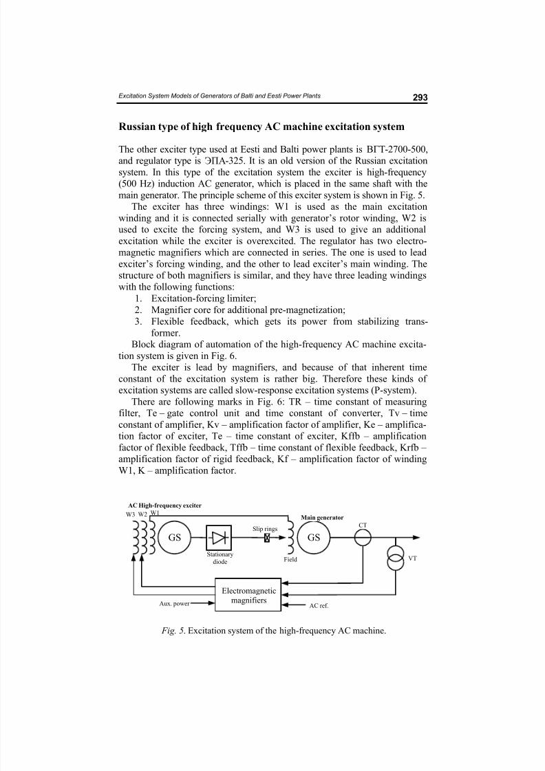
Russian type of high frequency AC machine excitation system
The other exciter type used at Eesti and Balti power plants is !"#-2700-500,
and regulator type is $%&-325. It is an old version of the Russian excitation
system. In this type of the excitation system the exciter is high-frequency
(500 Hz) induction AC generator, which is placed in the same shaft with the
main generator. The principle scheme of this exciter system is shown in Fig. 5.
The exciter has three windings: W1 is used as the main excitation
winding and it is connected serially with generator’s rotor winding, W2 is
used to excite the forcing system, and W3 is used to give an additional
excitation while the exciter is overexcited. The regulator has two electro-
magnetic magnifiers which are connected in series. The one is used to lead
exciter’s forcing winding, and the other to lead exciter’s main winding. The
structure of both magnifiers is similar, and they have three leading windings
with the following functions:
1. Excitation-forcing limiter;
2. Magnifier core for additional pre-magnetization;
3. Flexible feedback, which gets its power from stabilizing trans-
former.
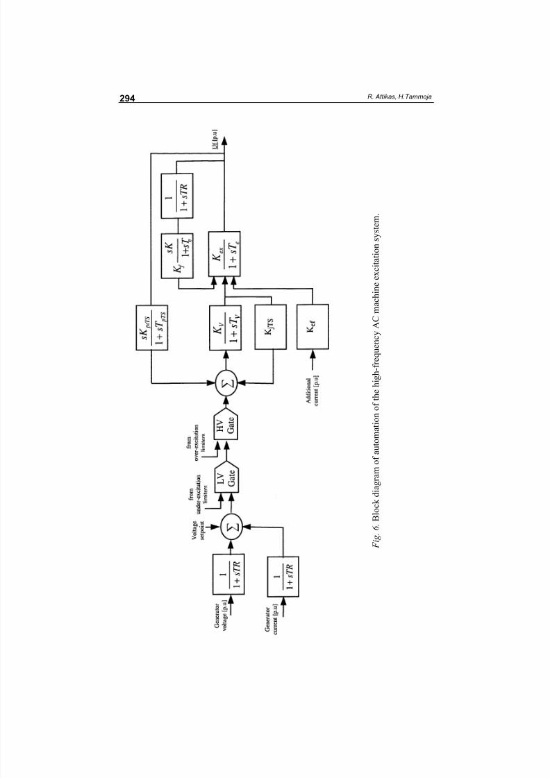
Block diagram of automation of the high-frequency AC machine excita-
tion system is given in Fig. 6.
The exciter is lead by magnifiers, and because of that inherent time
constant of the excitation system is rather big. Therefore these kinds of
excitation systems are called slow-response excitation systems (P-system).
There are following marks in Fig. 6: TR – time constant of measuringfilter, Te – gate control unit and time constant of converter, Tv – time
constant of amplifier, Kv – amplification factor of amplifier, Ke – amplifica-
tion factor of exciter, Te – time constant of exciter, Kffb – amplification
factor of flexible feedback, Tffb – time constant of flexible feedback, Krfb –
amplification factor of rigid feedback, Kf – amplification factor of winding
W1, K – amplification factor.
Fig. 5. Excitation system of the high-frequency AC machine.
GS
Main generator
GS
AC High-frequency exciter
W2W3 W1
Electromagnetic
magnifiers
Stationary
diode
Slip rings
Field
AC ref.
CT
VT
Aux. power
8/18/2019 oil-2007-2s-9
http://slidepdf.com/reader/full/oil-2007-2s-9 10/11
R. Attikas, H.Tammoja294
F
i g .
6 . B l o c k d i a g r a m o
f a u t o m a t i o n o
f t h e h i g h - f r e q u e n c y A C m a c h i n e e x c i t a t i o n s y s t e m .

8/18/2019 oil-2007-2s-9
http://slidepdf.com/reader/full/oil-2007-2s-9 11/11
Excitation System Models of Generators of Balti and Eesti Power Plants 295
Conclusions
In this paper two totally different excitation systems have been investigated.
One of them is an old Russian-type high-frequency AC machine excitation
system which was developed in the 60s and installed in the 70s into two
major power plants in Estonia. The other is a modern static excitation
system, which was installed in 2005 only in two blocks of the above-
mentioned power plants. This paper describes the requirements for the
excitation system. Both systems satisfy the basic requirements, but because
of their different structure their responses to grid disturbances are of
different strength. Automation block diagrams needed for dynamic calcula-
tion programs are proposed.
Acknowledgements
The authors thank the State target-financed research project (0142512s03)
for financial support of this study.
REFERENCES
1. Siemens PTI, PSS/E 30.2 Program Operational Manual, Volume II, 2005.
2. Kundur, P . Power System Stability and Control. – McGraw-Hill, 1994.
3. Anderson, P. M., Fouad, A. A. Power System Stability and Control. – Wiley-Interscience, 2003.
4. Rogers, R.. Power System Oscillations. – Kluwer Academic Publishers, 2000.
5. ABB, UNITROL5000 Excitation Systems for Medium and Large SynchronousMachines, 2000.
6. Barkan, J. D., Orehov, L. A. Automation of Power Systems. – Moscow, 1981 [in
Russian].
7. Motõgina, S. A. Operation of Electrical Part of Thermal Power Station. –Moscow, 1968 [in Russian].
8. Solovjev, I. I. Automatic Regulators of Synchronous Generators. – Moscow,
1981 [in Russian].
9. ABB Switzerland Ltd. Factory acceptance test procedure UNITROL5000,document nr. 3BHS125769 E62.
Received February 21, 2007