OH SER IES - Easy Kleen SER IES Easy-Kleen Pressure Systems LT D. 41 Earnhardt Road Sussex Corner ,...
28
OH SERI ES Easy-Kleen Pressure Systems LTD. 41 Earnhardt Road Sussex Corner , NB E4E 6A1 1 800 315 5533 MAGGOLD MAGPLUS MAG4000 MAGELE
Transcript of OH SER IES - Easy Kleen SER IES Easy-Kleen Pressure Systems LT D. 41 Earnhardt Road Sussex Corner ,...
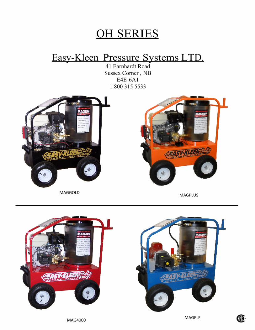
OH SERIES
Easy-Kleen Pressure Systems LTD. 41 Earnhardt Road
Sussex Corner , NB
E4E 6A1
1 800 315 5533
MAGGOLD MAGPLUS
MAG4000 MAGELE

2
Details
• The burner is set to produce the proper amount of temperature rise for 3.6 GPM
• Decreasing the pressure changes the GPM to the point where you have to compensate by:
1. Increasing the nozzle size in order to increase the GPM
2. Decrease the thermostat setting because the burner is heating less water
Contact Easy Kleen for kit to adjust pressure 1-800-315-5533 ext.1, Kevin Reid
• If these adjustments are not made, this may produce steam
• Steam is Dangerous
• The high pressure hose, trigger gun, nozzles, filters, valves, o-rings, and brass fittings are not rated
for steam and may fail causing serious injury or death.

3
These pressure washers are identical with the exception of type of gasoline engine
used (recoil start, electric start) and whether the burner’s are powered by 12V from
the gasoline engine or from line power @ 120V AC. For marketing purposes the
paint and decal colours vary.
Model Burner Orifice Burner Voltage
OH-200 1.65 120 V AC OH-200-12v 1.65 12 V DC OH-300 2.00-2.25 120 V AC OH-300-12v 2.00-2.25 12 V DC OH-400 2.00-2.25 120 V AC OH-400-12v 2.00-2.25 12 V DC

4
Easy-Kleen Pressure Washers
A) INTRODUCTION
Thank you for selecting a quality EASY-KLEEN product. We are pleased to have
you included among the many satisfied owners of EASY-KLEEN cleaning
machines. Years of engineering have gone into the development of these fine
products and only top quality components and materials are used throughout. Each
machine is carefully tested and inspected before leaving our plant to ensure years
of dependable performance.
To continue to receive satisfactory performance, remembering that this machine
represents a substantial investment on your part, and if properly cared for and
maintained it will return this investment many times over. As with all mechanical
equipment, your machine requires proper operation and maintenance as outlined in
this manual for maximum trouble free life..
PLEASE READ MANUALS CAREFULLY BEFORE USING MACHINE.
EXAMINE MACHINE AND CRATE CAREFULLY FOR SHIPPING DAMAGE
OR MISSING PARTS. REPORT PROMPTLY ANY SHORTAGES OR
DAMAGE CLAIMS TO FREIGHT CARRIER OR DEALER
B) OPERATING CHARACTERISTICS
Maximum Working Pressure
The water heater coils are designed to operate safely at working pressures up to
4000 PSI (OH-200 & OH-300) & 5000PSI (OH-400).
Each machine is equipped with a safety pressure relief valve which prevents
operation above safe pressure. If the high pressure pumping system requires a
lower relieving pressure for pump and motor protection, then the unloader/relief
valve on the pumping unit should be adjusted to the desired pressure rating.
Temperature Control
The water heater is equipped with a temperature control which shuts down the
burner in the event of excessive outlet temperature caused by insufficient water
flow through the heater coil. Do not set thermostat above 195˚F
High Pressure Switch
A pressure switch is installed in the high pressure water inlet line to prevent burner
operation in the absence of water flow. When the heater is used with shutoff gun
pumping systems, this switch controls the burner in conjunction with operation of
the trigger gun.

5
C) INSTALLATION INSTRUCTIONS
These water heaters are intended for outdoor use only due to their need for
adequate ventilation for the gasoline powered engines.
D) BASIC CONTROLS
The burners on these pressure washer's require a source of electrical power to create ignition. Optionally each model can generate 12V DC for this purpose or on the base model 120V electrical connection.
WARNING:
This controller must be provided with suitable overload and
overcurrent protection in accordance with the Canadian Electrical
Code part 1.
Avertissement:
Ce contrôleur doit être muni d’une protection contre la
surcharge et la sur intensité, conformément au Code
canadien de l’électircité, Première partie.
UNIT TO BE CONNECTED TO A (GFCI) OR TWIST
LOCK PLUG OR PERMANENT CONNECTION
A high pressure switch prevents burner operation without water flow. The
thermostat's "On-Off" function is provided for manual control.
E) OPERATING INSTRUCTIONS
To Operate Burner
Be sure water is flowing through water heater coil before turning on burner switch.
Start the gasoline engine and wait until a steady stream of water is flowing from
the spray gun. Turn thermostat to desired temperature. Burner will ignite and
remain in operation as long as there is sufficient water flow to satisfy the pressure
switch and temperature control. To shut off burner, turn temperature switch to
"Off".
Condensation From Coil
When cold water is being pumped through the heater coil and the burner is firing,
condensation may form at times on the coil and drip down into the burner
compartment. This can be particularly noticeable on cold, humid days giving the
false appearance of a leaking coil.

6
F) BURNER MAINTENANCE
Repair of the burner is to be done by authorized and trained burner professionals
only.
G) TROUBLE SHOOTING GUIDE -BURNER SYSTEM (see also Service
Manual) See page 26. BURNER FAILS TO START.
a. Check for loose or broken electrical connections
FIX Tighten or replace electrical connections
b. Pressure switch not operational
FIX Replace pressure switch.
c. Thermostat inoperative.
FIX Replace thermostat
d. Burner still won't function
FIX Refer to authorized burner repair facility.
H) GENERAL MAINTENANCE AND CARE If the water heater is likely to be exposed to freezing weather then it should be
winterized with anti-freeze. Circulation of an anti-freeze solution through the coil
by means of the pumping module is the most fail-safe method and should be used.
Alternate methods may not completely protect the components. Damage from
freezing is not a warrantable item.
Water Condition Use a softener on your water system if local water is known to be
high in mineral content. The advantages of soft water are very beneficial: prevents
scale buildup in heater coil, cleans better with considerably less detergent, prevents
streaking on painted surfaces and glass when rinsing.
Descaling Heater Coil If heater coils develop excessive scale buildup it should be
replaced as excessive scale in heater coil will reduce efficiency of the unit and
affect recovery capacity. Descaling via use of acid may be hazardous and is thus
not recommended.

7
EASY-KLEEN PRESSURE SYSTEMS
OPERATIONS MANUAL
OIL FIRED HOT WATER PRESSURE WASHER
INTRODUCTION
This manual has been prepared under the direction of our assembly and
service technicians. Their experience in designing, manufacturing,
installing and servicing our equipment from our company’s inception is
condensed in this manual. They know what information the end user
needs in order to get the optimum performance from their pressure
washer. Please read carefully.
This manual contains information that will be specific for your pressure
washer, as well as similar models.
Carefully review any additional manuals that have been included
with your system and follow ALL ADDITIONAL OPERATING
INSTRUCTIONS AND SAFETY NOTICES. They are specific for
the quality components that have been used to manufacture your
machine and are an integral part of the operating and maintenance
procedures.
The management & staff at Easy-Kleen Pressure Systems are proud of
the equipment that we design and manufacture and we thank you for
making us your # 1 choice in pressure washers. If you have any
questions please do not hesitate to call us, 1-800-315-5533.

8
USING YOUR MANUAL
This manual contains operational information that is specific for
Oil Fired Hot Water Pressure Washers.
IMPORTANT: ALL CAUTIONS AND SAFETY WARNINGS
MUST BE FOLLOWED TO AVOID INJURY.
Note particularly…
DO NOT USE GASOLINE, CRANKCASE DRAININGS, OR OIL CONTAINING
GASOLINE OR SOLVENTS *WARNING: RISK OF INJECTION OR SEVERE
INJURY. KEEP CLEAR OF NOZZLE. DO NOT DIRECT DISCHARGE STREAM AT
PERSONS. THIS EQUIPMENT IS TO BE USED ONLY BY TRAINED OPERATORS
*THE MACHINE MUST BE ELECTRICALLY GROUNDED *THIS MACHINE MUST
BE ATTENDED DURING OPERATI0N * DO NOT ADD FUEL WHEN ENGINE IS
RUNNING OR HOT
*NE PAS UTlLlSER D’ESSENCE, DE PRODUITS DE VIDANGE NI D’HUILE
CONTENANT DE L’ESSENCE OU DES SOLVANTS;*AVERTISSEMENT: RISQUE
D’INJECTION ET DE BLESSURES GRAVES. SE TENIR A L’ECART DU JET. NE PAS
DlRlGER LE JET DE SORTIEVERS D’AUTRES PERSONNES. CONFIER
L’UTILISATlON DE CE MATERIEL A UN OPERATEUR QUAL1FIE. *NE PAS FAlRE
FONCTIONNER CETTE MACHINE SANS SURVEILLANCE;* LA MACHINE DOlT
ETRE MISE A LA TERRE * NE PAS AJOUTER DE COMBUSTIBLE PENDANT SOlT
EN MARCHE OU SOlT QUE LE MOTEUR CHAUD.

9
SAFETY FIRST
The safe operation of our pressure washing systems is the FIRST priority of
Easy-Kleen Systems. This will only be achieved by following the operation
and maintenance instructions as explained in this manual and all other
enclosed manuals.
If you need further explanation of any of the information in this manual,
suspend any activity involving the equipment and call our toll free number
for assistance, 1-800-315-5533.
HIGH PRESSURE SPRAY CAN CAUSE SERIOUS INJURIES.
HANDLE THE SPRAY ASSEMBLY WITH CARE.
NEVER POINT PRESSURIZED SPRAY AT ANY PERSON OR
ANIMAL !
THIS MACHINE IS NOT TO BE CONNECTED TO A TYPE B GAS
VENT
NE PAS RACCORDER CET APPAREIL TUYAU D’EVACUATION DE
GAZ DU TYPE B
WARNING: RISK OF INJECTION OR SEVERE INJURY. KEEP CLEAR
OF NOZZLE. DO NOT DIRECT DISCHARGE STREAM AT PERSONS.
THIS EQUIPMENT IS TO BE USED ONLY BY TRAINED OPERATORS
AVERTISSEMENT: RISQUE D’INJECTION ET DE BLESSURES
GRAVES. SE TENIR A L’ECART DU JET. NE PAS DlRlGER LE JET
DE SORTIE VERS D’AUTRES PERSONNES. CONFIER
L’UTILISATlON DE CE MATERIEL A UN OPERATEUR QUALIFIE
THE MINIMUM CLEARANCE TO ANY COMBUSTIBLE MATERIALS
IS 12” (TWELVE INCHES).

10
OPERATING INSTRUCTIONS
1. Perform pre-start maintenance inspection on all applicable systems
prior to operating the machine. This is essential for the safe, effective
and efficient operation. You will get optimum performance from your
system ONLY if these instructions and inspections are followed. Any
indication that the pressure washing system was not operated and
maintained according to these instructions may cancel the
manufacturers’ warranty.
Location – Gasoline powered machines must be outdoors in a well
ventilated area.
Controls – All controls turned to the off position.
Pump oil level – Level the pressure washer. Be sure oil level is
correct on dip stick. If the level is low, add CORRECT oil to the
proper level. Refer to the Glossary or the suggested spare list for
proper oil to use. DO NOT OVER FILL.
Gas Engine - Gasoline levels – The engine is a 4 cycle and uses
regular octane, unleaded fuel. DO NOT USE MIXED FUEL.
Refer to the engine operation manual included with your
pressure-washing unit.
Gas Engine - Oil levels – The engine is a 4 cycle and uses 10W30
Detergent oil. Refer to Glossary or engine manual.
Oil Fired Burner- Oil Tank Levels – #2 Fuel is recommended fuel
for Oil Fired Hot Water Pressure Washers. It burns cleaner and
the burner requires less maintenance. Diesel fuel may be used as
an alternative. Do not overfill burner tank.
11
Electrically Operated Burners – Some models generate 12V from
the gasoline engine and provide the necessary power for the
burner. Others utilize a 120v connection which must be grounded.
IF YOU REQUIRE UPGRADES OR MODIFICATIONS TO
YOUR EXISTING ELECTRICAL SYSTEM IN ORDER TO
OPERATE YOUR PRESSURE WASHER, THEY MUST BE
PERFORMED BY A LICENSED ELECTRICIAN AND BE
COMPLETED IN ACCORDANCE TO ALL APPLICABLE
CODES IN YOUR AREA OF OPERATION.
Visually inspect all electrical components to assure they are in
good condition, showing no signs of exposure, breakage or
splicing.
Visually inspect all hoses, nozzles and guns to assure they are in
good condition. If replacements are necessary they must be rated
to withstand the machines operating pressure and temperatures.
2. Attach the high-pressure hose to the outlet coupling on the boiler or
pump. Ensure that the quick disconnect connections are tightly locked
together.
3. Attach the water source to the water inlet located on the pump. Turn on
the water source. The water source may be attached with a good quality
standard garden type hose, 1/2” is recommended. Connect the male
fitting into the female pump inlet swivel fitting making sure that the
inlet screen is intact and fitted correctly. WATER MUST BE IN
SUFFICIENT SUPPLY AND PRESSURE MUST BE BETWEEN 20 – 60 PSI TO ENSURE PROPER AND SAFE OPERATION. DO NOT
ATTACH A HOSE THAT IS SMALLER IN SIZE THAN THE INLET
OF THE PUMP.
4. Engage Pump Power Source and Burner
• Gasoline engine - refer to the instructions in the Engine Manual
MAKE SURE THAT THE ENGINE EXHAUST IS NOT FACING
ANY FLAMMABLE MATERIALS. Adjust the burner thermostat
control to ON at the desired temperature.
• Electric Motor – Manual – Turn burner switch to PUMP, adjust the
burner thermostat to desired temperature, turn switch to BURNER.
12
5. Burner operation – The machine must be operating with water source
connected and flowing prior to turning on the burner. IF YOU
EXPERIENCE IGNITION FAILURE, DO NOT ATTEMPT TO
RESTART BURNER! EXCESS FUEL AND VAPORS MAY HAVE
ACCUMULATED AND THE CHAMBER MAY BE HOT. THE UNIT
MUST COOL DOWN BEFORE RESTART CAN BE ATTEMPTED.
If the burner does not restart call the Easy-Kleen service
department or your local oil burner service technician.
6. Pressure adjustment - The pressure regulator (unloader) is located on the
pump. It controls the pressure being generated by the pressure washer.
This regulator may be adjusted to the desired pressure by turning the
adjustment knob or nut, depending on the unit purchased. Turning the
adjustment knob clockwise will increase the pressure. NEVER OPERATE
SYSTEM AT A PSI HIGHER THAN THE MAXIMUM RATING. This
machine has been adjusted to operate at a specifically rated PSI and
Volume as per the machine specifications. Pressure may be reduced for
lighter use by turning the Pressure Regulator/Unloader counter
clockwise.
7. Cleaning - Pull trigger on the pressure wand assembly to start cleaning.
To stop the pressurized water, release the trigger. DO NOT LEAVE
UNIT RUNNING WHEN NOT IN USE.
8. To stop Burner operation – Turn the control switch to off and run pump
for two minutes to cool the coil. Release trigger on the pressure wand
assembly. Turn off main power to engine, refer to manual. Release the
trigger for the second time in order to relieve the pump system of
pressure.
9. Prior to storage – inspect the pressure washer for any damage or required
maintenance. In cold weather, always store the unit in a heated area.
10.Warning – If unit is left running while not in use, pump damage may
occur. Do not leave unit running while not in use!
11.Battery Specifications for electric start systems only – Rating: 165CCA,
190 CA or better, dimensions: 8” x 5” x 6”.

13
CHEMICAL APPLICATION
DOWNSTREAM CHEMICAL INJECTION – STANDARD
NOTE: Do not remove back flow preventer as chemical may flow back into the
potable water source.
1. Chemical preparation – Select the detergent/chemical that best suits your
cleaning task. Prepare the dilution according to the manufacturers
instructions. The volume of chemical being used may be adjusted at the
valve located on the chemical injector.
2. Insert the intake hose, located on the chemical injector at the pump, into
the chemical being used.
3. Turn the adjustment knob on the wand or lance to the open position
OR when single lance is used, black nozzle will need to be used on
wand.
4. To apply chemical, engage the trigger on the pressure wand assembly.
Turn the chemical injector’s nipple to adjust flow.
5. Chemical can now be applied through the pressure wand assembly. It will
take 5 – 15 seconds for the chemical to travel to the spray nozzle. Volume
of chemical being used or water being supplied may be adjusted at the
Chemical Injector.
6. For best results apply chemical from bottom to top, allow the chemical
proper penetration time prior to rinsing. Do not allow the chemical to
dry. Rinse from the top to the bottom.
7. Optional high pressure chemical injection systems available. Please
contact Easy-Kleen.

14
WINTER PUMP/COIL PROTECTION
The following procedure MUST be used when the pressure washing unit is
stored at temperatures below 0°C/32°F between uses.
1. All water must be drained or blown (via compressed air) from system.
Connect a short piece of male fitted ½” garden type hose on to the
female inlet on the pump.
2. Place the open end of the hose into a wide mouthed container of full
strength, winter rated, vehicle windshield washing fluid or Anti-Freeze,
RATED FOR MINIMUM -40°C.
3. Connect the pressure wand assembly.
4. Start the engine and engage the trigger on the pressure gun. Operate
the system until the fluid runs the same color as the windshield washing
fluid. Your machine is now prepared for storage.
5. Blow out, disconnect fluid supply & pump out excess or cap end

15
GLOSSARY OF TERMS
PSI – Pounds per square inch. Pressure washers are designed and rated to operate
at a specific PSI. Operating at pressures exceeding the maximum rating could
result in damage to the unit and/or SEVERE PERSONAL INJURY.
GPM – Gallons per minute. The orifice on the pressure wand assembly has been
selected to deliver up to the maximum GPM for your machine.
PRESSURE WAND ASSEMBLY – This refers to the gun, wand, and nozzle.
PUMP – The pump moves the water through the system and delivers it to the
pressure wand assembly.
OIL, PUMP –The oil used within the pump to lubricate its operation. Important to
use only SAE 30 Wt Non Detergent
OIL, GASOLINE ENGINE – Machines which are powered by gasoline engines
need appropriate lubricant. Use 10W30 detergent oil.
UNLOADER VALVE – Is a valve located at the head of the pump for unloading
water back into the bypass when the trigger gun is shut off. It releases water when
the trigger on the gun is pressed. The unloader valve is preset at the factory and
should not be adjusted.
BURNER – The burner heats the water in hot water pressure washers. It is located
in the coil and may be powered by propane, gas, or oil.
DEMA – High-pressure chemical injector.
BACK FLOW PREVENTER – Device to prevent flow backwards into potable
water supply.

1
6
Easy-Kleen Pressure Washers
Service Manual
This m
anual is intended for technical personnel to assist in the diagnosis and repair of issues with pressure
washers.
This m
anual is not intended for use by non-technical personnel.
It is advised to always refer to competent technical personnel when repairs are advised to to avoid equipment
damage or potential personnel injury.
If you have any technical questions please do not hesitate to call us at 1-800-315-5533.

1
7
POWER SYSTEM DIAGNOSTIC
S - G
as M
otor Not Starting
PROBLEM
POSSIBLE CAUSE
SOLUTIO
N
Gas m
otor not starting
Fuel
Check to see if proper fuel levels are m
aintained
No ignition
Check ignition by removing spark plug from cylinder. If electric start, try starting using the recoil
starter.
Electric Starter/Battery
Recharge or replace battery.
F
use
blo
wn i
n k
ey s
wit
ch
18 a
mp e
ngin
e, o
pen
key s
wit
ch, re
pla
ce 3
0 a
mp f
use
Spark Plug - strong gas
smell
Flooded
Wait 5 m
inutes before attempting to restart.
No ignition
Check ignition by removing spark plug from cylinder. If electric start, try starting using the recoil
starter.
Bad plug
Check spark plug and replace if necessary. Carbon deposits can indicate a fouled plug or too
much fuel.
Plug does not fire
Poor connection
Inspect the ignition connection.
Bad m
agneto
Check the source of spark plug for engine ig
nition.
Bad ignition system
Poor connection
Check the source of spark for the engine ig
nition.
Spark Plug - no gas smell
No fuel to cylinder
Check fuel delivery from carburetor to cylinder. Check carburetor float bowl for fuel.
Fuel line restricted
Inspect fuel line to carburetor for restrictions or clogging. Flexible line m
ay be kinked.
Stuck carburetor float
Unstick float
Clogged carburetor needle valve
Unclog needle valve.
Bad fuel pump
Replace fuel pump.
1
8
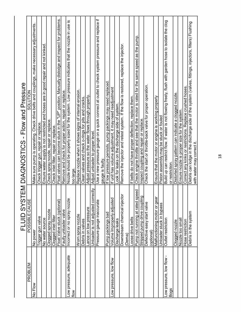
FLUID SYSTEM DIAGNOSTIC
S - Flow and Pressure
PROBLEM
POSSIBLE CAUSE
SOLUTIO
N
No Flow
No power
Make sure pump is operating. Check drive belts and couplings, make necessary adjustm
ents.
Trigger gun valve
Check trigger gun, repair or replace.
No water source
Ensure water supply is not restricted and hoses are in good repair and not kinked.
Clogged spray nozzle
Check spray nozzle, repair or replace.
Clogged in
let filter
Check inlet filter, repair or replace.
Float Valve stuck (optional)
Float valves can become stuck in the "UP" position. Manually dislodge and inspect for problems.
Faulty unloader valve
Remove and check for proper action, repair or replace.
Low pressure, adequate
flow
Incorrect or no spray nozzle
Nozzle should be properly sized for the system. Low pressure indicates that the nozzle in
use is
too large.
W
orn spray nozzle
Replace nozzle when it shows signs of internal e
rosion.
Debris in valves
Clean valves and check o-rings for pits and cracks.
Lance on low pressure
Adjust pressure so the water flows through properly.
Unloader is not adjusted correctly
Adjust unloader to proper level.
Pressure gauge in
accurate
Use a new pressure gauge on a quick connect at outlet to check system pressure and replace if
gauge is faulty.
Pump packings bad
If low pressure persists, pump packings m
ay need replaced.
Low pressure, low flow
Volume Improperly adjusted
If unit has volume adjustm
ent, it m
ay need readjustm
ent
Discharge leaks
Look for leaks on the discharge side of system.
Downstream chemical injector
(Dema)
Remove the injector and retest system. If the flow is restored, replace the injector.
Loose drive belts
If belts do not have proper deflection, replace them.
Pump not running at rated speed
Check engine throttle and see that the m
otor is rated for the same speed as the pump.
Stripped pump drive coupling
Inspect coupling and repair or replace.
Defective easy start valve
(optional)
Check the start or throttle-back valve for proper operation.
Malfunctioning m
otor or gear
Ensure that the m
otor or engine is working properly
Unloader stuck in bypass
Piston assembly m
ay be stuck or fouled
Low pressure, low flow -
Bogs
Outlet restriction
Build up can restrict flow. If water is not flowing freely, flush with garden hose to isolate the clog
or restriction.
Clogged nozzle
Distorted spray pattern can indicate a clogged nozzle.
Nozzle too small
Ensure nozzle is proper size for the system.
Hose restriction
Correct any kinks or restrictions. Replace crushed hoses.
Debris in the system
Debris can lodge in
the discharge side of the system (valves, fittings, injectors, filters) Flushing
with water may correct it.

1
9
PROBLEM
POSSIBLE CAUSE
SOLUTIO
N
Excessive pressure
Small spray nozzle
Nozzle m
ust be properly sized for the rated flow and pressure. Reset unloader or pressure relief
if nozzle size is changed.
Faulty pressure gauge
Check the pressure gauge using a properly calibrated pressure gauge on quick connects at the
equipment outlet.
Im
properly adjusted unloader
Adjust to the proper pressure using pressure gauge.
Faulty unloader
Check the unloader action. If it is not working properly, it may need repaired or replaced.
Pump chatters, caviataion,
vibration
Air in system
Inspect places where air can enter the system. i.e. fittings, hose, connections etc.
Chemical line not submerged
If the chemical valve is on, ensure that the chemical line is fully submerged in the chemical
Inlet line restricted
All inlet connections should be snug and not kinked to reduce the chances of pump starvation.
Inadequate water supply
W
ater supply to the system m
ust meet or exceed the rated flow (GPM) on the serial number
plate. Faucet must be completely opened or water above the tank outlet in a gravity fed system.
Float valve stuck (optional)
If float valve is stuck in the up position, water can not enter the float tank. Unstick valve if
possible of replace if necessary.
Turbulence in float tank (optional)
Excessive turbulence allows the pump to draw air into the system. Correct excessive turbulence.
Inlet or inlet strainer clogged
Regularly clean the inlet and inlet strainer to keep debris from entering the float tank
W
ater supply to hot
Inlet temperature should not exceed 140F - 160F range.
Inlet line vibrates
Air in system
Inspect places where air can enter the system, i.e.; fittings, hose, connections etc.
Debris in inlet check valves
If there is no float tank and the outlet line does no vibrate, the inlet check valve m
ay be clogged.
Remove debris. Check o-rings under valves.
Outlet line vibrates
Air in system
Inspect places where air can enter the system, i.e.; fittings, hose, connections etc.
Debris in inlet check valves
If there is no float tank and the outlet line does no vibrate, the inlet check valve m
ay be clogged.
Remove debris.
Pump packing bad
If they show signs of ware or damage, replace them.
Inlet and outlet lines vibrate
Inlet and outlet check valves
fouled
Look for the source of debris in the inlet and discharge check valves and remove.
2
0
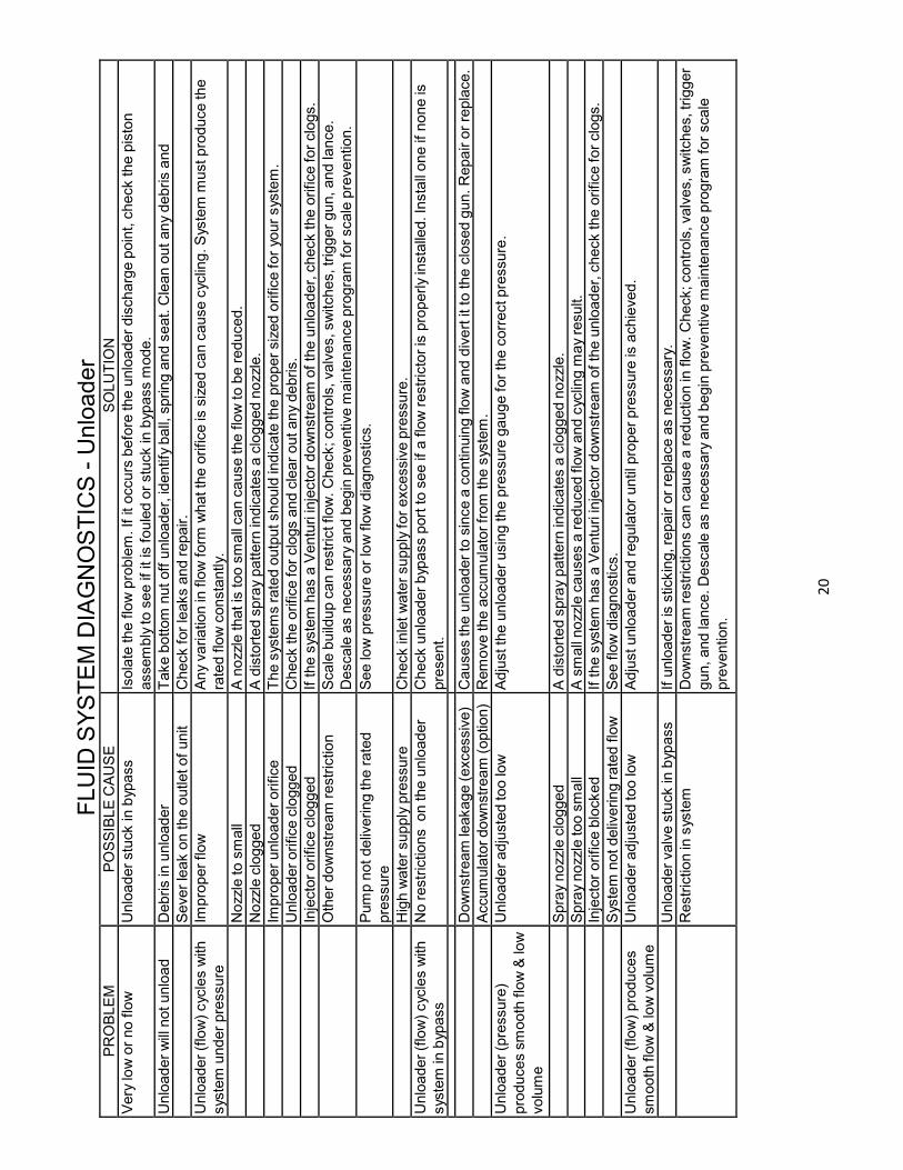
FLUID SYSTEM DIAGNOSTIC
S - Unloader
PROBLEM
POSSIBLE CAUSE
SOLUTIO
N
Very lo
w or no flow
Unloader stuck in bypass
Isolate the flow problem. If it occurs before the unloader discharge point, check the piston
assembly to see if it is fouled or stuck in bypass m
ode.
Unloader will not unload
Debris in unloader
Take bottom nut off unloader, id
entify ball, spring and seat. Clean out any debris and
Sever leak on the outlet of unit
Check for leaks and repair.
Unloader (flow) cycles with
system under pressure
Im
proper flow
Any variation in
flow form
what the orifice is sized can cause cycling. System m
ust produce the
rated flow constantly.
Nozzle to small
A nozzle that is too small can cause the flow to be reduced.
Nozzle clogged
A distorted spray pattern in
dicates a clogged nozzle.
Im
proper unloader orifice
The systems rated output should in
dicate the proper sized orifice for your system.
Unloader orifice clogged
Check the orifice for clogs and clear out any debris.
Injector orifice clogged
If the system has a Venturi injector downstream of the unloader, check the orifice for clogs.
Other downstream restriction
Scale buildup can restrict flow. Check; controls, valves, switches, trigger gun, and lance.
Descale as necessary and begin preventive m
aintenance program for scale prevention.
Pump not delivering the rated
pressure
See low pressure or low flow diagnostics.
High water supply pressure
Check inlet water supply for excessive pressure.
Unloader (flow) cycles with
system in bypass
No restrictions on the unloader
Check unloader bypass port to see if a flow restrictor is properly installed. Install one if none is
present.
Downstream le
akage (excessive)
Causes the unloader to since a continuing flow and divert it to the closed gun. Repair or replace.
Accumulator downstream (option)
Remove the accumulator from the system.
Unloader (pressure)
produces smooth flow & low
volume
Unloader adjusted too low
Adjust the unloader using the pressure gauge for the correct pressure.
Spray nozzle clogged
A distorted spray pattern in
dicates a clogged nozzle.
Spray nozzle too small
A small nozzle causes a reduced flow and cycling m
ay result.
Injector orifice blocked
If the system has a Venturi injector downstream of the unloader, check the orifice for clogs.
System not delivering rated flow
See flow diagnostics.
Unloader (flow) produces
smooth flow & low volume
Unloader adjusted too low
Adjust unloader and regulator until proper pressure is achieved.
Unloader valve stuck in byp
ass
If unloader is sticking, repair or replace as necessary.
Restriction in system
Downstream restrictions can cause a reduction in flow. Check; controls, valves, switches, trigger
gun, and lance. Descale as necessary and begin preventive m
aintenance program for scale
prevention.

2
1
Unloader (pressure)
produces lo
w flow and
norm
al p
ressure
Unloader adjusted too low
If the unloader is diverting flow to bypass it may be adjusted too low, readjust as necessary.
Spray nozzle to large
Ensure the proper nozzle is installed on system.
Internal n
ozzle erosion
The number of hours of usage can give you a clue to the extent of the ware. If in doubt, change
Insufficient pump pressure
Check pump seals and packings and tighten drive belts.
Unloader (flow) produces
low flow & norm
al p
ressure
Unloader adjusted too low
If unloader is diverting flow to bypass, readjust using the pressure gauge.
Nozzle too large
Ensure the proper sized nozzle is being used.
Unloader (pressure) leaks
from m
ain spring or
adjusting bolt
Shaft O
-ring in
valve body warn
Check O
-rings for ware or damage and replace as necessary.
Unloader (flow) pressure
increases when trigger
released
Unloader piston stuck or frozen
Check unloader shaft for proper action. Unstick piston and shaft or replace unloader.
Bypass port clogged or restricted
Ensure that unloader bypass port is not clogged
Excessive tension on m
ain spring
If tension is incorrect, adjust or replace as necessary.
Unloader (flow) leaks water
around adjusting bolt
Sleeve O
-ring worn
Check O
-rings for ware or damage and replace as necessary.

2
2
FLUID SYSTEM DIAGNOSTIC
S - Leaking
ANY LEAKS SHOULD BE REPAIRED ASAP TO PREVENT DAMAGE TO THE SYSTEM.
PROBLEM
POSSIBLE CAUSE
SOLUTIO
N
From inlet
Garden hose washer
Ensure the washer is present and in good condition.
From low pressure (inlet)
line fittings
Loose clamps or connections
Low pressure line should be properly sealed on barb and tightly clamped.
From float tank(option)
Float tank full of water or stuck
If float is not floating above water, check the float to see if it has filled up with water. If
necessary, drain and seal.
From pressure fittings
Fittings not tightened or taped, or
cracked
Usually m
etal to m
etal fittings should be taped with Teflon tape or lock tight to provide a tight
seal. (unless
fittings are provided with an O
-ring or seal)
From quick connects
Bad o-rings
If quick connect o-ring shows wear or damage, replace it.
From pump
Bad packing
If the seal leak is detected under the pump m
anifold, packing m
ay be worn and in need of
replacement.
From trigger gun
Bad rod o-ring
If o-rings show wear or damage, they m
ay need replaced.
Stripped connectors
Physical d
amage m
ay not be apparent, but unseen warping from freezing or extreme pressure
can still cause le
akage.
From nozzle
W
eep gun (optional)
If a weep gun has been installed, check the gun valve seat to ensure it is functioning properly.
Damage gun valve ball or seat
Inspect trigger gun valve assembly for damage or ware to ball or seat. Lodged debris can stop
valve from closing. Repair with kit or replace.
From unloader
Bad o-rings or seals
If quick connect o-ring shows wear, damage or im
proper seating.
From variable pressure
Lance(option)
Bad o-rings at adjusting knob
Inspect o-rings for ware or damage and replace as necessary.
Unloader will not unload
Debris in unloader
Take bottom nut off unloader, id
entify ball, spring and seat. Clean out any debris and
reassemble.
Sever leak on the outlet of unit
Check for leaks and repair.
From pressure relief valve
System over pressure
See pressure and flow diagnostics to find the cause of the excessive pressure and correct it.
Clogged nozzle
Spray pattern will be distorted if nozzle is clogged, clean out.
Trigger gun valve not working
If trigger gun valve action is not correct, repair or replace.
Excessive pressure spike
If water spurts from valve when trigger is released, check unloader adjustm
ent. Pressure spike
should be below the level where pressure relief valve is activated.
W
ear or damage to ball or seal
Inspect ball and seal for damage and adjust as necessary.
Im
proper relief valve adjustm
ent
Adjust valve properly.

2
3
FLUID SYSTEM DIAGNOSTIC
S - Trigger Gun/Spray Nozzle
PROBLEM
POSSIBLE CAUSE
SOLUTIO
N
No nozzle flow from nozzle
when trigger depressed.
Broken piston rod in trigger gun
If water flows through discharge hose without gun, check trigger gun valve piston rod and
replace if necessary.
Missing m
etal insert in trigger gun
(European style gun)
Inspect to assure in
sert is in place.
Blockage in system past gun
Check nozzle or spray accessory for blockage and clear it.
Excess pressure when
trigger gun is released
Excessive pressure spikes
After unloader increases pressure to a m
axim
um, further adjustm
ent will only in
crease the
pressure spikes. Re-adjust.
Flow not stopping when
trigger gun released
Broken return spring on trigger gun If trigger action is too loose, return spring m
ay need replaced.
Debris in gun valve
Debris in gun valve can stop piston return. Clear debris.
Trigger action sticks
Keeper plug too tight
It m
ay be possible to loosen plug slightly without leakage but it will likely need replaced.
Trigger gun leaks
Worn or bad o-ring
Check trigger gun o-rings for ware or damage and replace.
Stripped or loose connections
Physical d
amage m
ay not be apparent but unseen warping from freezing or sever overpressure
may still cause le
aking.
No chemical
Chemical valve closed
Black nozzle
Open chemical valve. If It chatters with no chemical delivery, air is being drawn from the
upstream side of the pump. Check fittings, connections and ensure the inlet line is fully
submerged into the chemical jug.
Chemical dried up in the injector
inspect and clean as necessary.
Chemical foot strainer clogged
May be a strainer or check valve. Ensure that the ball is not stuck or clogged.
Chemical line kinked
Chemical line kinking or binding prevents chemical d
elivery.
Chemical line too long
An overly long chemical line can prevent the pump from drawing chemical into the system. Try
installing a shorter line.
Chemical too dilute
Verify chemical strength.
No adjustm
ent for low pressure
Downstream in
jectors only - Low pressure is required for most injectors to draw chemical. If no
adjuster exists it may need low pressure spray nozzle in
stalled on the lance.
Incorrect injector orifice
If not properly sized for the systems rated output, chemical delivery problems will result. Check
serial p
late for specs.
Excessive chemical
Valve improperly adjusted, check
knob on injector
To properly adjust, a chemical flow m
eter may be used to precisely m
easure chemical flow.
Chemical dilution to strong
Verify chemical strength.
Spray pattern irregular
Clogged nozzle
Spray pattern will be distorted if nozzle is clogged.
Volume proper, pressure
low
Nozzle to large
Ensure that the nozzle is sized properly sized for the system
Internal n
ozzle wear
A loss of pressure m
ay result form
gradual n
ozzle wear. Replace a nozzle of correct size.
Pressure proper, volume
low
Clogged nozzle
Spray pattern will be distorted if nozzle is clogged. Check nozzle for clogging if the unit has a
pressure unloader.
2
4
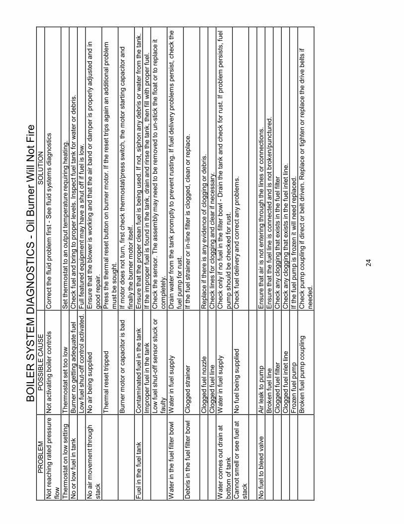
BOILER SYSTEM DIAGNOSTIC
S - O
il Burner Will Not Fire
PROBLEM
POSSIBLE CAUSE
SOLUTIO
N
Not reaching rated pressure
flow
Not activating boiler controls
Correct the fluid problem first - See fluid systems diagnostics
Therm
ostat on low setting
Therm
ostat set too low
Set therm
ostat to an output temperature requiring heating.
No or low fuel in tank
Burner no getting adequate fuel
Check fuel and bring to proper levels. Inspect fuel tank for water or debris.
Low fuel shut-off control a
ctivated.
Full featured equipment may have a shut off if fuel is low.
No air m
ovement through
stack
No air being supplied
Ensure that the blower is w
orking and that the air band or damper is properly adjusted and in
good repair.
Therm
al reset tripped
Press the therm
al reset button on burner motor. If the reset trips again an additional problem
must be sought.
Burner motor or capacitor is bad
If m
otor does not turn, first check therm
ostat/press switch, the m
otor starting capacitor and
finally the burner motor itself.
Fuel in the fuel tank
Contaminated fuel in the tank
Ensure that the proper clean fuel is being used. If not, siphon any debris or water from the tank.
Im
proper fuel in the tank
If the improper fuel is found in the tank, drain and rinse the tank, then fill with proper fuel.
Low fuel shut-off sensor stuck or
faulty
Check the sensor. The assembly m
ay need to be removed to un-stick the float or to replace it
completely.
Water in the fuel filter bowl
Water in fuel supply
Drain water from the tank promptly to prevent rusting. If fuel delivery problems persist, check the
fuel pump for rust.
Debris in the fuel filter bowl
Clogged strainer
If the fuel strainer or in-line filter is clogged, clean or replace.
Clogged fuel nozzle
Replace if there is any evidence of clogging or debris.
Clogged fuel line
Check lines for clogging and clear if necessary.
Water comes out drain at
bottom of tank
Water in fuel supply
Check only if no fuel in the filter bowl - Drain the tank and check for rust. If problem persists, fuel
pump should be checked for rust.
Cannot smell or see fuel at
stack
No fuel being supplied
Check fuel delivery and correct any problems.
No fuel to bleed valve
Air leak to pump
Ensure that air is not entering through the lines or connections.
Broken fuel line
Ensure that the fuel line is connected and is not broken/punctured.
Clogged fuel filter
Check any clogging that exists in the fuel filter
Clogged fuel inlet line
Check any clogging that exists in the fuel inlet line.
Froze
n fuel pump
If the fuel pump is froze
n it will need replaced.
Broken fuel pump coupling
Check pump coupling if direct or belt driven. Replace or tighten or replace the drive belts if
needed.
2
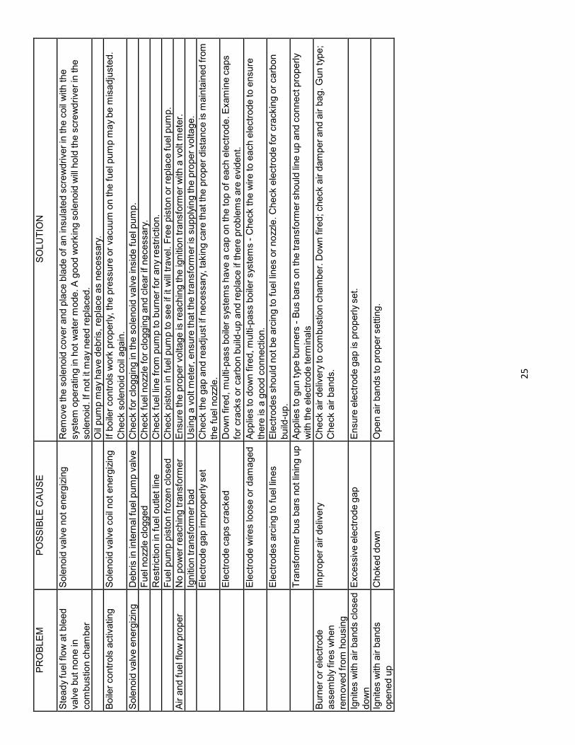
5
PROBLEM
POSSIBLE CAUSE
SOLUTIO
N
Steady fuel flow at bleed
valve but none in
combustion chamber
Solenoid valve not energizing
Remove the solenoid cover and place blade of an insulated screwdriver in the coil with the
system operating in hot water mode. A good working solenoid will hold the screwdriver in the
solenoid. If not it m
ay need replaced.
Oil pump m
ay have debris, replace as necessary.
Boiler controls activating
Solenoid valve coil not energizing
If boiler controls work properly, the pressure or vacuum on the fuel pump m
ay be m
isadjusted.
Check solenoid coil again.
Solenoid valve energizing
Debris in internal fuel pump valve
Check for clogging in
the solenoid valve in
side fuel pump.
Fuel nozzle clogged
Check fuel nozzle for clogging and clear if necessary.
Restriction in fuel outlet line
Check fuel line from pump to burner for any restriction.
Fuel pump piston froze
n closed
Check piston in
fuel pump to see if it will travel. Free piston or replace fuel pump.
Air and fuel flow proper
No power reaching transform
er
Ensure the proper voltage is reaching the ignition transform
er with a volt m
eter.
Ignition transform
er bad
Using a volt m
eter, ensure that the transform
er is supplying the proper voltage.
Electrode gap improperly set
Check the gap and readjust if necessary, taking care that the proper distance is m
aintained from
the fuel nozzle.
Electrode caps cracked
Down fired, multi-pass boiler systems have a cap on the top of each electrode. Examine caps
for cracks or carbon build-up and replace if there problems are evident.
Electrode wires loose or damaged Applies to down fired, multi-pass boiler systems - Check the wire to each electrode to ensure
there is a good connection.
Electrodes arcing to fuel lines
Electrodes should not be arcing to fuel lines or nozzle. Check electrode for cracking or carbon
build-up.
Transform
er bus bars not lining up Applies to gun typ
e burners - Bus bars on the transform
er should line up and connect properly
with the electrode term
inals
Burner or electrode
assembly fires when
removed from housing
Improper air delivery
Check air delivery to combustion chamber. Down fired; check air damper and air bag. Gun type;
Check air bands.
Ignites with air bands closed
down
Excessive electrode gap
Ensure electrode gap is properly set.
Ignites with air bands
opened up
Choked down
Open air bands to proper setting.

2
6
PROBLEM
POSSIBLE CAUSE
SOLUTIO
N
Flame in
term
ittently lifts and
returns to gas port "candles" Gas velocity exceeds flame speed If gas flow is not properly regulated, the regulator may need to be replaced. Gas line m
ay be too
small.
Flame height changes
suddenly
Uneven gas supply pressure
Check orifice for partial b
lockage. If no blockage found, ensure that the gas supply and regulator
are working properly.
Flame floats around the
combustion chamber
Insufficient air
Check stack for fuel restriction and correct. It may require new ventilation if the original system is
inadequate.
Flame has yellow tip
Flame speed im
proper
Check for proper gas pressure while burner is operating.
Flame comes out from
under burner housing
Insufficient air and ventilation
Usually occurs at ignition. Check stack for fuel restriction.
Gas burns inside the burner
tube - roars
Burner underrated
Inquire about a burner with the proper rated capacity.
Burner pops when gas is
shut off
Flame travels back into burner
Flame travel when the gas is shut off does not damage the unit.
BOILER SYSTEM DIAGNOSTIC
S -Gas Burner Will Not Fire
PROBLEM
POSSIBLE CAUSE
SOLUTIO
N
No arc at the ignition pilot
assembly
Spark gap incorrect
Check the spark gap and reset if necessary. Check for air in the propane line.
Ignition m
odule bad
Check the ignition m
odule and replace if necessary.
Ignition operating properly
Boiler controls m
alfunctioning
Check boiler controls for good operation and correct problems.
Boiler controls operating
properly
Gas valve m
alfunctioning
If pilot and boiler controls operate properly, the problem m
ay exist with the gas valve. Replace if
necessary
BOILER SYSTEM DIAGNOSTIC
S Abnorm
al
Flame Characteristics - Gas Fired
BOILER SYSTEM DIAGNOSTICS
Water Output Temperature Too Low - O
il or Gas Fired
PROBLEM
POSSIBLE CAUSE
SOLUTIO
N
Burner firing norm
ally but
with outlet temp lower than
rated
Therm
ostat set too low
Set the therm
ostat to proper output temperature.
Burner firing constantly
Inlet water too cold
If inlet water is freezing to the touch, the boiler may not be able to reach the desired temperature
increase. Use a water supply with a higher temperature.
Sooting
Soot build up on the coil can keep the water from reaching the desired temperature. Remove all
soot from the coil and check for smoking.
Scaling
The outlet fitting to the hose can get scale build-up and reduce heat exchange. Descale and
prevent further build-up.
2
7
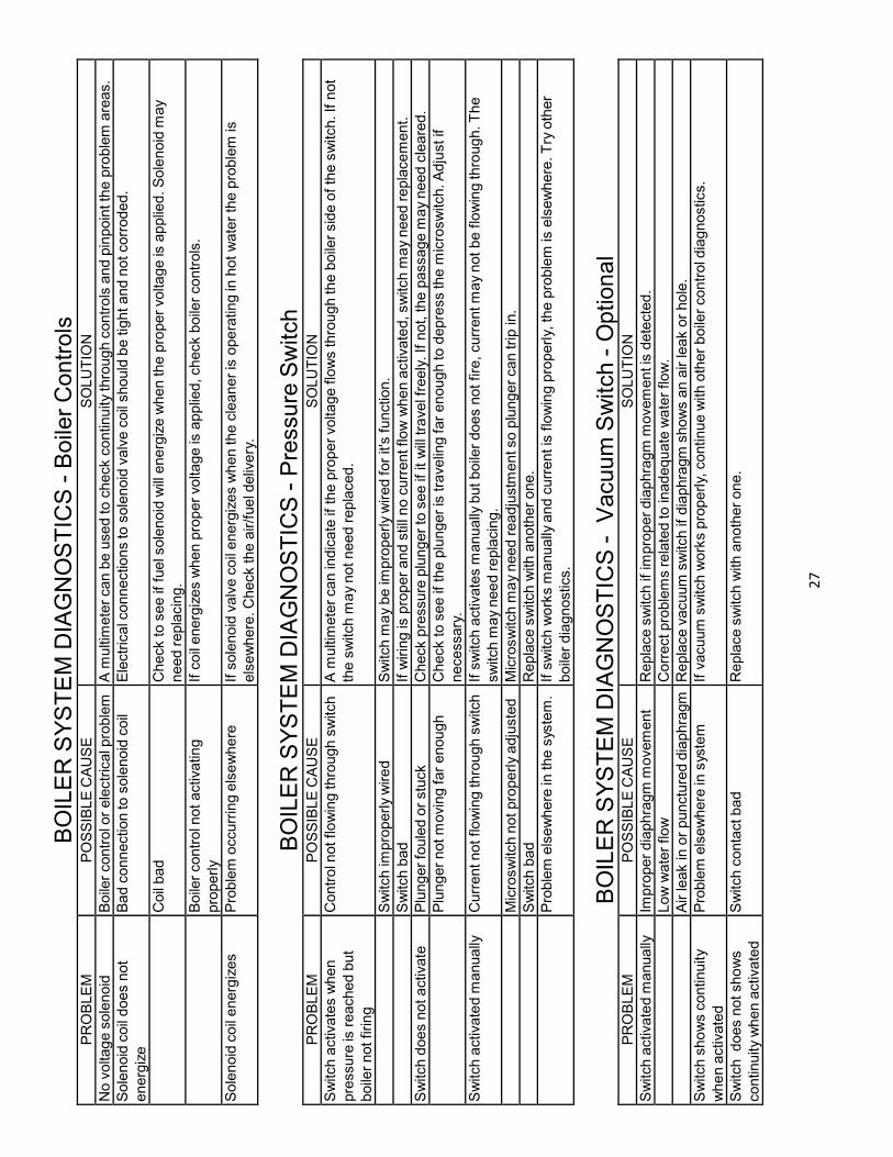
BOILER SYSTEM DIAGNOSTIC
S - Boile
r Controls
PROBLEM
POSSIBLE CAUSE
SOLUTIO
N
No voltage solenoid
Boiler control o
r electrical p
roblem
A m
ultim
eter can be used to check continuity through controls and pinpoint the problem areas.
Solenoid coil does not
energize
Bad connection to solenoid coil
Electrical connections to solenoid valve coil should be tight and not corroded.
Coil bad
Check to see if fuel solenoid will energize when the proper voltage is applied. Solenoid m
ay
need replacing.
Boiler control n
ot activating
properly
If coil energizes when proper voltage is applied, check boiler controls.
Solenoid coil energizes
Problem occurring elsewhere
If solenoid valve coil energizes when the cleaner is operating in hot water the problem is
elsewhere. Check the air/fuel d
elivery.
BOILER SYSTEM DIAGNOSTIC
S - Pressure Switch
PROBLEM
POSSIBLE CAUSE
SOLUTIO
N
Switch activates when
pressure is reached but
boiler not firing
Control n
ot flowing through switch A m
ultim
eter can indicate if the proper voltage flows through the boiler side of the switch. If not
the switch m
ay not need replaced.
Switch im
properly wired
Switch m
ay be improperly wired for it's function.
Switch bad
If wiring is proper and still no current flow when activated, switch m
ay need replacement.
Switch does not activate
Plunger fouled or stuck
Check pressure plunger to see if it will travel freely. If not, the passage m
ay need cleared.
Plunger not moving far enough
Check to see if the plunger is traveling far enough to depress the m
icroswitch. Adjust if
necessary.
Switch activated m
anually
Current not flowing through switch If switch activates m
anually but boiler does not fire, current may not be flowing through. The
switch m
ay need replacing.
Microswitch not properly adjusted
Microswitch m
ay need readjustm
ent so plunger can trip in.
Switch bad
Replace switch with another one.
Problem elsewhere in
the system.
If switch works m
anually and current is flowing properly, the problem is elsewhere. Try other
boiler diagnostics.
BOILER SYSTEM DIAGNOSTIC
S - Vacuum Switch - O
ptional
PROBLEM
POSSIBLE CAUSE
SOLUTIO
N
Switch activated m
anually
Im
proper diaphragm m
ovement
Replace switch if improper diaphragm m
ovement is detected.
Low water flow
Correct problems related to inadequate water flow.
Air leak in or punctured diaphragm
Replace vacuum switch if diaphragm shows an air leak or hole.
Switch shows continuity
when activated
Problem elsewhere in
system
If vacuum switch works properly, continue with other boiler control d
iagnostics.
Switch does not shows
continuity when activated
Switch contact bad
Replace switch with another one.
2
8
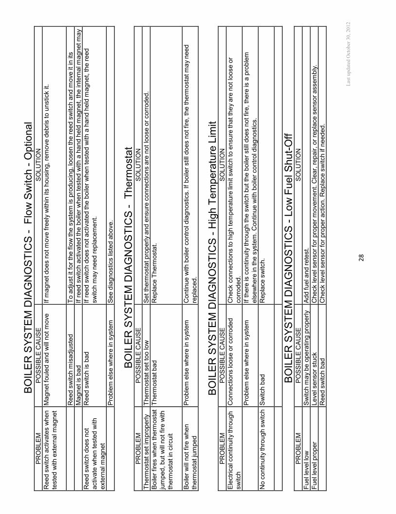
BOILER SYSTEM DIAGNOSTIC
S - Flow Switch - O
ptional
PROBLEM
POSSIBLE CAUSE
SOLUTIO
N
Reed switch activates when
tested with external m
agnet
Magnet fouled and will not move
If m
agnet does not move freely within its housing, remove debris to unstick it.
Reed switch m
isadjusted
To adjust it for the flow the system is producing, loosen the reed switch and m
ove it in its
Magnet is bad
If reed switch activated the boiler when tested with a hand held m
agnet, the internal m
agnet may
Reed switch does not
activate when tested with
external m
agnet
Reed switch is bad
If reed switch does not activated the boiler when tested with a hand held m
agnet, the reed
switch m
ay need replacement.
Problem else where in system
See diagnostics listed above.
BOILER SYSTEM DIAGNOSTIC
S - Therm
ostat
PROBLEM
POSSIBLE CAUSE
SOLUTIO
N
Therm
ostat set im
properly
Therm
ostat set too low
Set therm
ostat properly and ensure connections are not loose or corroded.
Boiler fires when therm
ostat
jumped, but will not fire with
therm
ostat in circuit
Therm
ostat bad
Replace Therm
ostat.
Boiler will not fire when
therm
ostat jumped
Problem else where in system
Continue with boiler control diagnostics. If boiler still does not fire, the therm
ostat may need
replaced.
BOILER SYSTEM DIAGNOSTIC
S - High Temperature Lim
it
PROBLEM
POSSIBLE CAUSE
SOLUTIO
N
Electrical continuity through
switch
Connections loose or corroded
Check connections to high temperature limit switch to ensure that they are not loose or
corroded.
Problem else where in system
If there is continuity through the switch but the boiler still does not fire, there is a problem
elsewhere in the system. Continue with boiler control diagnostics.
No continuity through switch Switch bad
Replace switch.
BOILER SYSTEM DIAGNOSTIC
S - Low Fuel Shut-Off
PROBLEM
POSSIBLE CAUSE
SOLUTIO
N
Fuel level low
Switch m
ay be operating properly
Add fuel and retest.
Fuel level proper
Level sensor stuck
Check level sensor for proper movement. Clear, repair, or replace sensor assembly.
Reed switch bad
Check level sensor for proper action. Replace switch if needed.
L
ast
upd
ated
Oct
ob
er 3
0, 20
12