Oge Marques and Nitish Barman - Florida Atlantic University
28
307 0-8493-XXXX-X/02/$0.00+$1.50 ' 2003 by CRC Press LLC 13 Wireless Communications Using Bluetooth Oge Marques and Nitish Barman CONTENTS 13.1 Introduction ................................................................................................ 308 13.2 Overview .................................................................................................... 309 13.2.1 Masters and Slaves ...................................................................... 310 13.2.2 Frequency Hopping Spread Spectrum (FHSS) and Time-Division Duplexing (TDD) ................................................ 310 13.2.3 Piconets and Scatternets .............................................................. 310 13.3 Protocol Stack ............................................................................................ 311 13.3.1 The Radio Layer .......................................................................... 313 13.3.2 The Baseband Layer .................................................................... 314 13.3.2.1 Device Addressing...................................................... 314 13.3.2.2 Frequency Hopping .................................................... 315 13.3.2.3 Link Types (ACL and SCO) ...................................... 315 13.3.2.4 Packet Denitions....................................................... 316 13.3.2.5 Logical Channels ........................................................ 319 13.3.2.6 Channel Control ......................................................... 320 13.3.2.7 Error Checking and Correction .................................. 320 13.3.2.8 Security ....................................................................... 321 13.3.3 The LMP Layer ........................................................................... 322 13.3.4 The L2CAP Layer ....................................................................... 325 13.3.4.1 L2CAP Channel Management ................................... 327 13.3.5 The SDP Layer ............................................................................ 327 13.4 Bluetooth Proles Specication................................................................. 329 13.4.1 GAP.............................................................................................. 329 13.4.2 SDAP ........................................................................................... 330 13.4.3 SPP ............................................................................................... 330 13.4.4 GOEP ........................................................................................... 331 13.5 Additional Considerations.......................................................................... 331 13.5.1 Power Management ..................................................................... 331 13.5.2 Security ........................................................................................ 332
Transcript of Oge Marques and Nitish Barman - Florida Atlantic University

13 Wireless Communications Using Bluetooth
Oge Marques and Nitish Barman
CONTENTS
13.1 Introduction ................................................................................................30813.2 Overview ....................................................................................................309
13.2.1 Masters and Slaves ......................................................................31013.2.2 Frequency Hopping Spread Spectrum (FHSS) and
Time-Division Duplexing (TDD) ................................................31013.2.3 Piconets and Scatternets ..............................................................310
13.3 Protocol Stack ............................................................................................31113.3.1 The Radio Layer ..........................................................................31313.3.2 The Baseband Layer ....................................................................314
13.3.2.1 Device Addressing......................................................31413.3.2.2 Frequency Hopping ....................................................31513.3.2.3 Link Types (ACL and SCO) ......................................31513.3.2.4 Packet DeÞnitions.......................................................31613.3.2.5 Logical Channels........................................................31913.3.2.6 Channel Control .........................................................32013.3.2.7 Error Checking and Correction..................................32013.3.2.8 Security.......................................................................321
13.3.3 The LMP Layer ...........................................................................32213.3.4 The L2CAP Layer .......................................................................325
13.3.4.1 L2CAP Channel Management ...................................32713.3.5 The SDP Layer ............................................................................327
13.4 Bluetooth ProÞles SpeciÞcation.................................................................32913.4.1 GAP..............................................................................................32913.4.2 SDAP ...........................................................................................33013.4.3 SPP...............................................................................................33013.4.4 GOEP ...........................................................................................331
13.5 Additional Considerations..........................................................................33113.5.1 Power Management .....................................................................33113.5.2 Security ........................................................................................332
3070-8493-XXXX-X/02/$0.00+$1.50© 2003 by CRC Press LLC

308
Handbook of Wireless Internet
13.6 Concluding Remarks..................................................................................332Acknowledgment ...................................................................................................333References..............................................................................................................333
13.1 INTRODUCTIONBluetooth is a wireless communications standard that allows compliant devices toexchange information with each other. The technology makes use of the globallyavailable, unlicensed ISM (Industrial, ScientiÞc, and Medical) band. Although it wasinitially developed as a cable-replacement technology, it has grown into a standardthat is designed to support an open-ended list of applications (including multimediaapplications). As a short-range, low-power technology with data rates of up to 720kbps, it is ideally suited for use in establishing ad hoc personal area networks (PANs).
The Bluetooth speciÞcation emerged from a study undertaken by EricssonMobile Communications in 1994 to Þnd alternatives to using cables to facilitatecommunications between mobile phones and accessories. As this study grew inscope, other companies joined Ericsson�s efforts to utilize radio links as cablereplacements. In 1998 these companies � Ericsson, Intel, IBM, Toshiba, and Nokia� formally founded the Bluetooth Special Interest Group (SIG). In July 1999 thiscore group of promoters published version 1.0 of the Bluetooth speciÞcation.1
Shortly after the speciÞcation was published, the group of core promoters wasenlarged further with the addition of four more companies: Microsoft, Agere Systems(a Lucent Technologies spin-off), 3COM, and Motorola.
In addition to the core promoters group, many hundreds of companies havejoined the SIG as Bluetooth adopter companies. In fact, any incorporated companycan join the SIG as an adopter company by signing the Bluetooth SIG membershipagreement (available on the Bluetooth Web site1). Joining the SIG entitles an adoptercompany to a free license to build Bluetooth-based products, as well as the right touse the Bluetooth brand.
The list of adopter companies continues to grow in part because there is no costassociated with intellectual property rights, but primarily because there are so manypotential applications and usage models for Bluetooth:
1. Cordless desktop: In this cable-replacement usage model, all (or most) ofthe peripheral devices (e.g., mouse, keyboard, printer, speakers, etc.) areconnected to the PC cordlessly.
2. Ultimate headset: This usage model would allow one headset to be used withmyriad devices, including telephones, portable computers, stereos, etc.
3. Automatic synchronization: This usage model makes use of the hiddencomputing paradigm, which focuses on applications in which devicesautomatically carry out certain tasks on behalf of the user without userintervention or awareness. Consider the following scenario: A user attendsa business meeting, exchanges contact information with other attendees,and stores this information on a PDA. Upon returning to the user�s ofÞce,the PDA automatically establishes a Bluetooth link with the user�s desktopPC and the information stored on the PDA is automatically uploaded tothe PC. All this happens without the user�s conscious involvement.

Wireless Communications Using Bluetooth
309
There are many other usage models that have been proposed by the BluetoothSIG as well as other contributors. With increasing numbers of applications beingdeveloped around Bluetooth, it is highly likely that the technology will be wellaccepted by the market.
The remainder of this chapter is organized as follows. Section 13.2 provides abroad overview of the Bluetooth protocol stack and introduces some concepts andterminology. Section 13.3 gives a more-detailed explanation of the key features ofthe various layers of the Bluetooth protocol stack. Section 13.4 introduces the secondvolume of the Bluetooth speciÞcation, the ProÞle speciÞcation. It serves as a basicintroduction to the concept of Bluetooth proÞles, and gives a brief description ofthe fundamental proÞles. Section 13.5 discusses security and power managementissues, two items that are critical for the acceptance of Bluetooth in the consumermarket. Finally, Section 13.6 concludes this chapter with some anecdotal evidenceof the interest evinced in Bluetooth application development.
13.2 OVERVIEW
The Bluetooth speciÞcation comprises two parts:
1. The core speciÞcation,2 which deÞnes the Bluetooth protocol stack andthe requirements for testing and qualiÞcation of Bluetooth-based products
2. The proÞles speciÞcation,3 which deÞnes usage models that providedetailed information about how to use the Bluetooth protocol for varioustypes of applications
The Bluetooth core protocol stack consists of the following Þve layers:
1. Radio speciÞes the requirements for radio transmission � including fre-quency, modulation, and power characteristics � for a Bluetooth trans-ceiver.
2. Baseband deÞnes physical and logical channels and link types (voice ordata); speciÞes various packet formats, transmit and receive timing, chan-nel control, and the mechanism for frequency hopping (hop selection) anddevice addressing.
3. Link Manager Protocol (LMP) deÞnes the procedures for link set up andongoing link management.
4. Logical Link Control and Adaptation Protocol (L2CAP) is responsible foradapting upper-layer protocols to the baseband layer.
5. Service Discovery Protocol (SDP) � allows a Bluetooth device to queryother Bluetooth devices for device information, services provided, andthe characteristics of those services.
In addition to the core protocol stack, the Bluetooth speciÞcation also deÞnesother layers that facilitate telephony, cable replacement, and testing and qualiÞcation.The most important layers in this group are the Host Controller Interface (HCI) andRFCOMM, which simply provides a serial interface that is akin to the EIA-232

310
Handbook of Wireless Internet
(formerly RS-232) serial interface. HCI provides a standard interface between thehost controller and the Bluetooth module, as well as a means of testing/qualifyinga Bluetooth device.
The Bluetooth protocol stack is discussed in greater detail in Section 13.3. Inthe remainder of this section we will introduce key concepts and terminology thatare helpful for an understanding of Bluetooth technology.
13.2.1 MASTERS AND SLAVES
All active Bluetooth devices must operate either as a master or a slave. A masterdevice is a device that initiates communication with another Bluetooth device. Themaster device governs the communications link and trafÞc between itself and theslave devices associated with it. A slave device is the device that responds to themaster device. Slave devices are required to synchronize their transmit/receive timingwith that of the masters. In addition, transmissions by slave devices are governedby the master device (i.e., the master device dictates when a slave device maytransmit). SpeciÞcally, a slave may only begin its transmissions in a time slotimmediately following the time slot in which it was addressed by the master, or ina time slot explicitly reserved for use by the slave device.
13.2.2 FREQUENCY HOPPING SPREAD SPECTRUM (FHSS) AND TIME-DIVISION DUPLEXING (TDD)
Bluetooth employs a frequency hopping technique to ensure secure and robustcommunication. The hopping scheme is such that the Bluetooth device hops fromone 1-MHz channel to another in a pseudorandom manner � altogether there are 79such 1-MHz channels deÞned by the SIG. Typically, each hop lasts for 625 ms. Atthe end of the 625-ms time slot, the device hops to a different 1-MHz channel. Thetechnology ensures full-duplex communication by utilizing a TDD scheme. In thesimplest terms this means that a Bluetooth device must alternate between transmit-ting and receiving (or at least listening for) data from one time slot to the next. TheBluetooth speciÞcation facilitates this TDD scheme by (1) using numbered timeslots (the slots are numbered according to the clock of the master device), and (2)mandating that master devices begin their transmissions in even-numbered time slotsand slave devices begin their transmissions in odd-numbered time slots (Figure 13.1).Both these techniques will be further discussed in Section 13.3.
13.2.3 PICONETS AND SCATTERNETS
Bluetooth technology furthers the concept of ad hoc networking where deviceswithin range of each other can dynamically form a localized network for an indeÞniteduration. Ad hoc Bluetooth networks in which all member devices share the same(FHSS) channel are referred to as piconets.4 A piconet can consist of up to eightdevices: a single master and up to seven slave devices. The frequency hoppingsequence of the piconet is determined by the Bluetooth device address (BD_ADDR)of the master device. At the time that the piconet is established, the master device�saddress and clock are communicated to all slave devices on the piconet. The slaves

Wireless Communications Using Bluetooth
311
use this information to synchronize their hop sequence as well as their clocks withthat of the master�s.
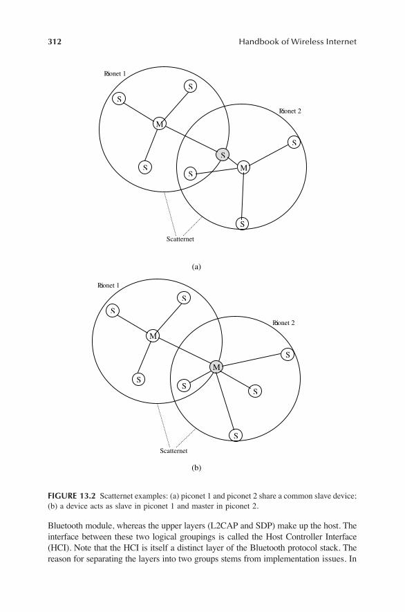
Scatternets (Figure 13.2) are created when a device becomes an active memberof more than one piconet. Essentially, the adjoining device shares its time slotsamong the different piconets. Scatternets are not limited to a combination of onlytwo piconets; multiple piconets may be linked together to form a scatternet. However,as the number of piconets increases, the total throughput of the scatternet decreases.Note that the piconets that make up a scatternet still retain their own FH sequencesand remain distinct entities.
Scatternets offer two advantages over traditional collocated ad hoc networks.First, because each individual piconet in the scatternet retains its own FH sequence,the bandwidth available to the devices on any one piconet is not degraded by thepresence of the other piconets (although the probability of collisions may increase).Second, devices on different piconets are able to �borrow� services from each otherif they are on the same scatternet.
13.3 PROTOCOL STACK
The Þve layers of the Bluetooth core protocol are divided into two logical parts(Figure 13.3). The lower three layers (Radio, Baseband, and LMP) comprise the
FIGURE 13.1 Frequency hopping and time-division duplexing. During even-numbered slots,the master device transmits and the slave device receives. During odd-numbered slots, theslave device transmits and the master device receives.
10 11 12 13 14 15 16
10 11 12 13 14 15 16
time slots
time slots
R F c h a n n e l
R F c h a n n e l
Master Device
Slave Device
transmit
receive
312
Handbook of Wireless Internet
Bluetooth module, whereas the upper layers (L2CAP and SDP) make up the host. Theinterface between these two logical groupings is called the Host Controller Interface(HCI). Note that the HCI is itself a distinct layer of the Bluetooth protocol stack. Thereason for separating the layers into two groups stems from implementation issues. In
FIGURE 13.2 Scatternet examples: (a) piconet 1 and piconet 2 share a common slave device;(b) a device acts as slave in piconet 1 and master in piconet 2.
(a)
(b)
Piconet 2
M
M
S
S
S
S
S
S
S
Piconet 1
Scatternet
Piconet 2
M
S
M
S
S
S
S
S
Piconet 1
Scatternet
S

Wireless Communications Using Bluetooth
313
many Bluetooth systems the lower layers reside on separate hardware than the upperlayers of the protocol. A good example of this is a Bluetooth-based wireless LANcard. Because the PC to which the LAN card connects typically has enough spareresources to implement the upper layers in software, the LAN card itself onlycontains the lower layers, thus reducing hardware complexity and user cost. In sucha scenario the HCI provides a well-deÞned, standard interface between the host (thePC) and the Bluetooth module (the LAN card).
13.3.1 THE RADIO LAYER
Bluetooth devices operate in the 2.4-GHz ISM band. In North America, Europe, andmost of the rest of the world, a bandwidth of 83.5 MHz is available in the ISMband. In France, however, the ISM band is much narrower. The Bluetooth SIG hasactively lobbied the French regulatory bodies to release the full ISM band; Franceis expected to comply by 2003. Although the Bluetooth speciÞcation deÞnes aseparate RF speciÞcation for the narrower (French) band, we will not consider it here.
The ISM band is littered with millions of RF emitters ranging from randomnoise generators, such as sodium vapor street lamps, to well-deÞned, short-rangeapplications, such as remote entry devices for automobiles. Microwave ovens areparticularly noisy and cause signiÞcant interference. Clearly, the ISM band is not avery reliable medium. Bluetooth overcomes the hurdles presented by the pollutedenvironment of the ISM band by employing techniques that ensure the robustnessof transmitted data. SpeciÞcally, Bluetooth makes use of frequency hopping (alongwith fairly short data packets) and adaptive power control techniques in order toensure the integrity of transmitted data.
FIGURE 13.3 Bluetooth protocol stack.
Link Manager Protocol
Radio
Baseband
Bluetooth Module
Applications
Logical Link Control And Adaptation Protocol
SDP RFCOMM
Host
HCI
314
Handbook of Wireless Internet
The Bluetooth Radio speciÞcation deÞnes a frequency hopping spread spectrumradio transceiver operating over multiple RF channels. The speciÞcation divides the83.5-MHz bandwidth available in the ISM band into 79 RF channels of 1 MHz each,a 2-MHz lower guard band, and a 3.5-MHz upper guard band. The channel frequen-cies are deÞned as
2402 + k MHz
where k = 0, 1, �, 78.In order to maximize the available channel bandwidth, the data rate for the RF
channels is set at 1 Mbps. Gaussian frequency shift keying (GFSK) is used as themodulation scheme, with a binary 1 deÞned as a positive frequency deviation fromthe carrier frequency and a binary 0 deÞned as a negative frequency deviation.
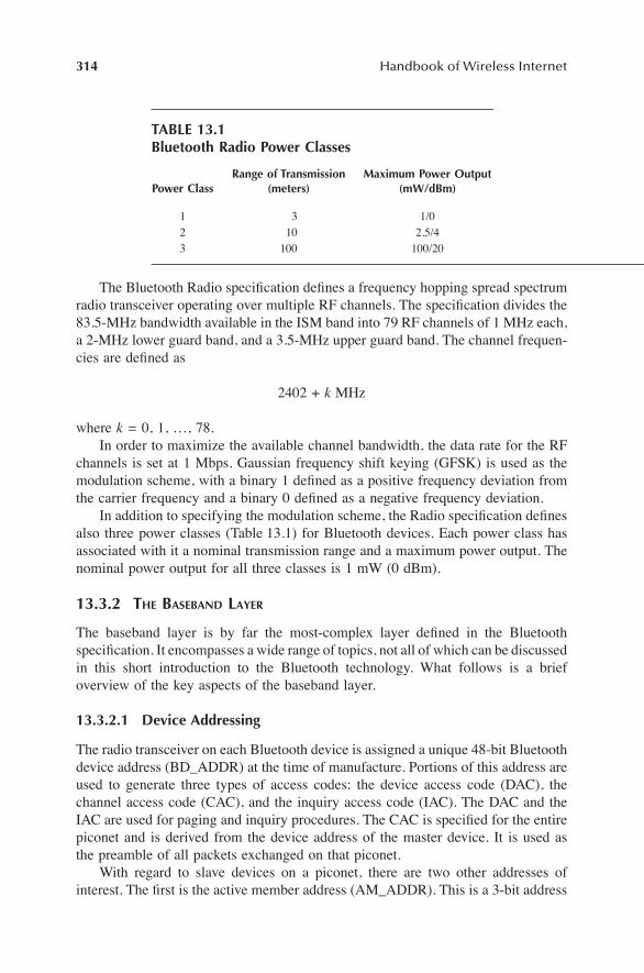
In addition to specifying the modulation scheme, the Radio speciÞcation deÞnesalso three power classes (Table 13.1) for Bluetooth devices. Each power class hasassociated with it a nominal transmission range and a maximum power output. Thenominal power output for all three classes is 1 mW (0 dBm).
13.3.2 THE BASEBAND LAYER
The baseband layer is by far the most-complex layer deÞned in the BluetoothspeciÞcation. It encompasses a wide range of topics, not all of which can be discussedin this short introduction to the Bluetooth technology. What follows is a briefoverview of the key aspects of the baseband layer.
13.3.2.1 Device Addressing
The radio transceiver on each Bluetooth device is assigned a unique 48-bit Bluetoothdevice address (BD_ADDR) at the time of manufacture. Portions of this address areused to generate three types of access codes: the device access code (DAC), thechannel access code (CAC), and the inquiry access code (IAC). The DAC and theIAC are used for paging and inquiry procedures. The CAC is speciÞed for the entirepiconet and is derived from the device address of the master device. It is used asthe preamble of all packets exchanged on that piconet.
With regard to slave devices on a piconet, there are two other addresses ofinterest. The Þrst is the active member address (AM_ADDR). This is a 3-bit address
TABLE 13.1Bluetooth Radio Power Classes
Power ClassRange of Transmission
(meters)Maximum Power Output
(mW/dBm)
1 3 1/02 10 2.5/43 100 100/20
Wireless Communications Using Bluetooth
315
that is assigned to an active slave device on the piconet. Because the piconet mayhave seven active slaves at any given time, a slave�s AM_ADDR uniquely identiÞesit within its piconet. The second address of interest is the parked member address(PM_ADDR). This is an 8-bit address assigned to slave devices that are parked, i.e.,devices that are not active on the piconet but remain synchronized to the piconet�smaster. An active slave device loses its AM_ADDR as soon as it is parked. Similarly,a parked device that becomes active immediately relinquishes its PM_ADDR andtakes on an AM_ADDR. Note that the reactivated device may or may not be assignedthe same AM_ADDR that it was assigned before it was parked.
13.3.2.2 Frequency Hopping
In order to ensure secure and robust data transmission, Bluetooth technology utilizesa frequency hopping spread spectrum technique. Under this scheme, Bluetoothdevices in a piconet hop from one RF channel to another in a pseudorandomsequence. Typically, a hop occurs once at the beginning of every time slot. Becauseeach time slot has a 625-ms duration, the nominal hopping frequency is 1600 hopsper second. All devices that are part of the same piconet hop in synchrony. Thehopping sequence is based on the master�s BD_ADDR and consequently is uniquefor each piconet.
Because there can be multiple piconets operating in close proximity to eachother, it is important to minimize collisions between the devices in different piconets.The speciÞcation addresses this issue in two ways. First, the pseudorandom hopselection algorithm is designed to generate the maximum distance between adjacenthop channels. Second, the duration of the time slots is kept very small (625 ms).Time slots of such short duration ensure that even if a collision occurs it will notlast long. A collision is unlikely to recur during the next time slot because the piconetwill have hopped to a different RF channel.
Strictly speaking, the baseband speciÞcation deÞnes a different hoppingsequence for different types of operations. The earlier description is that of thechannel hopping sequence, which utilizes all 79 RF channels and deÞnes a uniquephysical channel for the piconet. However, the other hopping sequences (associatedwith device discovery procedures such as paging and inquiry) utilize only 32 RFchannels.
One Þnal note: It was previously stated that the nominal hop rate is 1600 hopsper second. This is true only for packets (discussed later) that occupy a single timeslot. For packets that occupy three (or Þve) time slots, the same RF channel is usedfor transmission during all three (or Þve) time slots.
13.3.2.3 Link Types (ACL and SCO)
The baseband speciÞcation deÞnes two types of links between Bluetooth devices.
1. Synchronous Connection Oriented (SCO) link: This is a bidirectional (64kbps each way), point-to-point link between a master and a single slavedevice. The master maintains the SCO link by using reserved time slots

316
Handbook of Wireless Internet
at regular intervals. The slots are reserved as consecutive pairs: one fortransmissions from the master to the slave and the other for transmissionsin the opposite direction. The master can support up to three SCO linkssimultaneously. A slave device can support up to three simultaneous SCOlinks with one master or � if it is the adjoining device on a scatternet �it can support up to two simultaneous SCO links with two differentmasters. SCO links are used for exchanging time-bound user information(e.g., voice). Packets sent on these links are never retransmitted.
2. Asynchronous Connectionless (ACL) link: This is a point-to-multipointlink between the master and all the slaves on a piconet. An ACL link canutilize any packet that is not reserved for an SCO link. The master canexchange packets with any slave on the piconet on a per-slot basis, includ-ing slaves with which it has an established SCO link. Only one ACL linkcan exist between any master�slave pair. ACL links are used for theexchange of control information and user data, therefore packet retrans-mission is applied to ACL packets received in error.
13.3.2.4 Packet Definitions
The baseband layer deÞnes the format and structure of the various packet types usedin the Bluetooth system. The length of a packet can range from 68 bits (shortenedaccess code) to a maximum of 3071 bits. A typical packet (Figure 13.4), however,consists of a 72-bit access code, a 54-bit packet header, and a variable length (0 to2745 bits) payload.
Every packet must begin with an access code (see Section 3.2.1). The accesscode is used for synchronization and identiÞcation at either the device level(DAC/IAC) or the piconet level (CAC).
The packet header contains link control information, so it is important to ensureits integrity. This is accomplished by applying a 1/3-rate FEC scheme to the entireheader. The packet header consists of six different Þelds:
1. AM_ADDR (3-bit Þeld): This Þeld contains the active member addressof the slave device that transmitted the packet (or, if the master sent thepacket, the AM_ADDR of the slave device to which the packet wasaddressed).
2. TYPE (4-bit Þeld) : This Þeld identiÞes the type of packet, as explainedlater in this section.
3. FLOW (1-bit Þeld): This Þeld is used for providing ßow control informa-tion on an ACL link. A value of 0 (STOP) indicates a request to the senderto stop sending information, whereas a value of 1 (GO) indicates that thereceiver is once again ready to receive additional packets. If no packet isreceived from the receiver, a GO is implicitly assumed.
FIGURE 13.4 Packet structure of a typical Bluetooth packet.
Access Code Packet Header Payload (variable length)
0
Wireless Communications Using Bluetooth
317
4. ARQ (1-bit Þeld): This Þeld is used for acknowledging payload dataaccompanied by a CRC (cyclic redundancy check). If the payload wasreceived without error, a positive acknowledgment (ACK) is sent; other-wise, a negative acknowledgment (NACK) is sent. An ACK correspondsto a binary 1 and a NACK corresponds to a binary 0. Note that NACK isthe default value for this Þeld and is implicitly assumed.
5. SEQN (1-bit Þeld): This Þeld is used for a very simple sequential num-bering scheme for transmitted packets. The SEQN bit is inverted for eachnew transmitted packet containing a payload accompanied by a CRC. ThisÞeld is required for Þltering out retransmissions at the destination.
6. HEC (8-bit Þeld) : This Þeld, the header error check, is used for ascer-taining the integrity of the header. If the header is received in error, theentire packet is ignored.
The payload portion of the packet is used to carry either voice or data informa-tion. Typically, packets transmitted on SCO links carry voice information � with theexception of the DV packet type, which carries both voice and data � and packetstransmitted on ACL links carry data. For packets carrying voice information, thepayload length is Þxed at 240 bits (except DV packets). Packets carrying data, onthe other hand, have variable length payloads that are segmented into three parts: apayload header, payload body, and a CRC.
The payload header is either one or two bytes long. It speciÞes the logicalchannel on which the payload is to be carried, provides ßow control information forthe speciÞed channel, and indicates the length of the payload body. The only dif-ference between the one-byte and two-byte headers is that the two-byte headers usemore bits to specify the length of the payload body. The payload body simplycontains the user host data and the 16-bit CRC Þeld is used for performing errorchecking on the payload body.
13.3.2.4.1 Packet TypesThe packets deÞned for use in the Bluetooth system (Table 13.2) are identiÞed bythe 4-bit TYPE Þeld in the packet header. As is evident from the length of the TYPEÞeld, 16 possible packet types can be deÞned altogether. Bluetooth packet types canbe categorized in four broad groups: control packets, single-slot packets, three-slotpackets, and Þve-slot packets. Single-slot packets require only one time slot forcomplete transmission. Similarly, three-slot and Þve-slot packets require three andÞve time slots, respectively, for complete transmission. The single-slot, three-slot,and Þve-slot packets are deÞned differently for the two different link types (SCOand ACL), while the control packets are common to both links.
The four control packets deÞned in the speciÞcation are:
1. NULL: This packet type is used to return acknowledgments and ßowcontrol information to the source.
2. POLL: This packet is used by the master to poll slave devices in a piconet.Slave devices must respond to this packet even if they have no informationto send.

318
Handbook of Wireless Internet
3. FHS: The frequency hop selection packet is used to identify the frequencyhop sequence before a piconet is established or when an existing piconetchanges to a new piconet as a result of a master�slave role switch. Thiscontrol packet contains the BD_ADDR and clock of the sender (recallthat the master�s device address and clock are used to generate a pseudo-random frequency hop sequence). In addition, the packet contains alsothe AM_ADDR to be assigned to the recipient along with other informa-tion required in establishing a piconet.
4. DM1: The DM1 (data�medium rate) packet is used for supporting controlinformation on any link. This is necessary, for example, when synchronousinformation (on an SCO link) must be interrupted in order to supplycontrol information. In an ACL link, this packet can be used to carry userdata. The packet�s payload can contain up to 18 bytes of information. Thepayload data is followed by a 16-bit CRC. Both the data and the CRCare encoded with a 2/3-rate forward error correction (FEC) scheme.
The remaining 12 packet types are deÞned differently for each link. Some packettypes have not yet been deÞned or have been set aside for future use.
13.3.2.4.2 SCO PacketsAll packets deÞned speciÞcally for the SCO link are single-slot packets. They allhave a 240-bit payload and do not include a CRC. The Þrst three SCO packets aredesigned to carry high-quality voice (HV) information (64 kbps) and are deÞned asfollows:
TABLE 13.2Bluetooth Packet Types
Packet GroupType Code
Packet Name on SCO Link
Packet Name on ACL Link
Number of Slots
0000 NULL NULL 1Control group 0001 POLL POLL 1
0010 FHS FHS 10011 DM1 DM1 10100 UndeÞned DH1 10101 HV1 UndeÞned 1
Single-slot group 0110 HV2 UndeÞned 10111 HV3 UndeÞned 11000 DV UndeÞned 11001 UndeÞned AUX1 11010 UndeÞned DM3 3
Three-slot group 1011 UndeÞned DH3 31100 UndeÞned UndeÞned 31101 UndeÞned UndeÞned 3
Five-slot group 1110 UndeÞned DM5 51111 UndeÞned DH5 5

Wireless Communications Using Bluetooth
319
� HV1: This packet contains 10 bytes of data and is protected by 1/3-rateFEC. Because one packet can carry about 1.25 ms of speech, HV1 packetsneed to be transmitted once every two time slots.
� HV2: This packet contains 20 bytes of data and is protected by 2/3-rateFEC. Because one packet can carry about 2.5 ms of speech, HV2 packetsonly need to be transmitted once every four time slots.
� HV3: This packet contains 30 bytes of data and is not encoded with anerror correction scheme. Because one packet can carry about 3.75 ms ofspeech, HV3 packets need to be transmitted only once every six time slots.
The last packet type deÞned for the SCO link is the DV (combined data andvoice) packet. This packet contains a 10-byte voice Þeld and a data Þeld containingup to 10 bytes of data. The data Þeld is encoded with 2/3-rate FEC and is protectedby a 16-bit CRC. It is interesting to note that the voice and data information containedin this packet are treated completely differently. The voice information � which issynchronous � is never retransmitted, whereas the data information is retransmittedif it is found to be in error. So, for example, if the data Þeld of a packet is receivedin error, the packet is retransmitted (i.e., the data Þeld contains the same information),but the voice Þeld contains new (different) information.
13.3.2.4.3 ACL PacketsSix different packet types have been deÞned speciÞcally for the ACL link. All theACL packets are designed to carry data information and are distinguished from oneanother by two basic criteria: (1) whether they are encoded with a FEC scheme, and(2) how many time slots they require for complete transmission. The packet typesprotected with an FEC scheme are referred to as medium data rate (DM) packets,whereas the unprotected packets are referred to as high data rate (DH) packets.
There are two DM packet types deÞned: DM3 and DM5. Both these packettypes are similar to the DM1 control packet in that they are protected with a 2/3-rate FEC scheme. The difference is that unlike DM1, which requires one time slotfor complete transmission, DM3 and DM5 require three time slots and Þve timeslots, respectively. Additionally, as one might expect, DM5 packets can carry moredata than DM3 packets, which in turn can carry more data than DM1.
Three different DH packet types are deÞned for the ACL link: DH1, DH3 andDH5. All these packets can carry more data than their DM counterparts because theDH packets are not encoded with an error correction scheme. As with the DM packettypes, DH3 and DH5 carry more information than DH1.
The sixth packet type deÞned for the ACL link is the AUX1 (auxiliary) packettype. This packet type is very similar to DH1 except it does not contain a CRC code.
The remaining packet types have not been deÞned as yet and have been set asideto accommodate packet types that may be required in the future.
13.3.2.5 Logical Channels
Bluetooth speciÞcation deÞnes Þve logical channels for carrying either link controland management information or user data.

320
Handbook of Wireless Internet
The two channels that carry link control information are the link control (LC)channel and the link manager (LM) channel. The LC logical channel is mapped tothe header of every packet (except the ID packet) exchanged on a Bluetooth link.This channel carries low level link information such as ßow control, ARQ, etc. TheLM channel is typically carried on protected DM packets and it can utilize eitherlink type (SCO or ACL). A packet used for the LM channel is identiÞed by an L_CHvalue of 11 in the packet�s header. The LM channel carries LMP trafÞc and thereforetakes priority over user data channels.
Three logical channels are deÞned for conveying user data: the user asynchro-nous (UA) channel, the user isochronous (UI) channel, and the user synchronous(US) channel. The UA and UI channels are normally mapped to the payload ofpackets transmitted over an ACL link, but they can be mapped also to the data Þeldof the DV packet on an SCO link. The US channel carries synchronous user data(e.g., voice communication) and is mapped to the payload Þeld of packets transmittedover an SCO link.
13.3.2.6 Channel Control
Channel control deals with the establishment of a piconet and adding/removingdevices to/from a piconet. The speciÞcation deÞnes two primary states for a Blue-tooth device: standby and connected. The standby state is the default, low-powerstate. A device is in the connected state when it is a member of a piconet, i.e., whena device is synchronized to the hop sequence of a piconet.
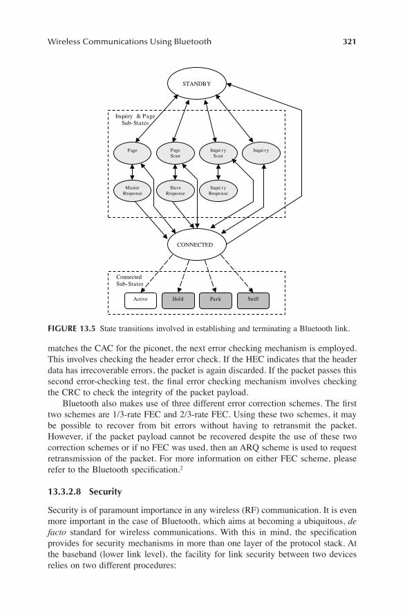
Devices do not transition directly from the standby state to the connected state,and vice versa. In fact, the speciÞcation describes several substates that a devicemust transition through in order to move from one primary state to the other. Thesesubstates are associated with inquiry and paging procedures that are required forslave devices to join or leave the piconet. Figure 13.5 depicts the state transitionsinvolved in going from the standby state to the connected state and back. Theobservant reader will note that there is a direct transition from the connected stateback to the standby state. This direct transition occurs only in case of a hard reset.Normally, devices must methodically detach from the piconet, which requires tran-sitioning through different substates.
The Bluetooth system makes provisions for connected devices to be put intoone of three low-power modes while remaining synchronized to the hop sequenceof the piconet. These modes (discussed further in Section 3.3) can be considered assubstates of the connected state (Figure 13.5).
13.3.2.7 Error Checking and Correction
Bluetooth provides a variety of error checking and error correction mechanisms.Bluetooth packets can be checked for errors at three levels. When a packet is received,the receiver immediately checks its channel access code (recall that the CAC is thepreamble for all packets). If the CAC embedded in the packet does not match theCAC of the piconet, then either the packet was received in error, or the packet wasdestined for another piconet. In either case, the packet is discarded. If the CAC
Wireless Communications Using Bluetooth 321
matches the CAC for the piconet, the next error checking mechanism is employed.This involves checking the header error check. If the HEC indicates that the headerdata has irrecoverable errors, the packet is again discarded. If the packet passes thissecond error-checking test, the Þnal error checking mechanism involves checkingthe CRC to check the integrity of the packet payload.
Bluetooth also makes use of three different error correction schemes. The Þrsttwo schemes are 1/3-rate FEC and 2/3-rate FEC. Using these two schemes, it maybe possible to recover from bit errors without having to retransmit the packet.However, if the packet payload cannot be recovered despite the use of these twocorrection schemes or if no FEC was used, then an ARQ scheme is used to requestretransmission of the packet. For more information on either FEC scheme, pleaserefer to the Bluetooth speciÞcation.2
13.3.2.8 Security
Security is of paramount importance in any wireless (RF) communication. It is evenmore important in the case of Bluetooth, which aims at becoming a ubiquitous, defacto standard for wireless communications. With this in mind, the speciÞcationprovides for security mechanisms in more than one layer of the protocol stack. Atthe baseband (lower link level), the facility for link security between two devicesrelies on two different procedures:
FIGURE 13.5 State transitions involved in establishing and terminating a Bluetooth link.
Connected Sub-States
Inquiry & Page Sub-States
Page
Master Response
Page Scan
Inqui ry
Inqui ry Response
Slave Response
Inqui ry Scan
CONNECTED
STANDBY
Active Hold Park Sniff

322 Handbook of Wireless Internet
1. Authentication: Procedure used to verify the identity claimed by a Blue-tooth device
2. Encryption: Procedure used to encode user data so that it is unintelligibleuntil decoded using a speciÞc key
The security algorithms deÞned in the baseband speciÞcation utilize the follow-ing four parameters:
1. BD_ADDR: Publicly known 48-bit address of the device2. Authentication key: 128-bit secret key preconÞgured with the device3. Privacy key: Variable length (4 to 128 bits) secret key that is preconÞgured
also with the device4. Random number: 128-bit number used for device authentication
In addition to these key responsibilities, the baseband layer addresses otherissues, including transmit/receive timing, data whitening, and encoding of audioinformation for transmission over Bluetooth links.
13.3.3 THE LMP LAYER
The Link Manager Protocol is responsible for establishing and maintaining ACLand SCO links, and establishing, managing, and terminating the connections betweendifferent devices. LMP provides a mechanism for the link managers (LMs) onseparate devices to exchange messages containing link management informationwith each other. These messages are sent as LMP protocol data units (PDUs) andare carried in the payload of single-slot packets (DM1 or DV) transmitted on theLM logical channel.
Because LMP PDUs are used for link management, they have been assigned avery high priority. Consequently, LMP PDUs may be transmitted during slotsreserved for an SCO link. The PDU contains three Þelds:
1. A 1-bit transaction ID Þeld, which speciÞes whether the link managementtransaction was initiated by the master (0) or the slave (1) device
2. A 7-bit OpCode Þeld, which identiÞes the PDU and provides informationabout the PDUs payload
3. A payload Þeld, which contains the actual information necessary to man-age the link
Many PDUs have been deÞned for the different transactions deÞned in the speci-Þcation. Two of the most general response PDUs are LMP_Accepted andLMP_Not_Accepted. Although many link management transactions have been deÞnedin the speciÞcation, not all of them are mandatory. However, the LM on every Bluetoothdevice must be able to recognize and respond to any of the speciÞed transactions. Incase the LM on the receiving device does not support a particular transaction, it muststill respond to the requesting device�s LM with an LMP_Not_Accepted PDU.

Wireless Communications Using Bluetooth 323
In the remainder of this section we will brießy mention some of the more-important link management transactions deÞned in the speciÞcation. These transac-tions are grouped into three broad categories: link control, power management, andsecurity management.
Link management transactions used for link control include:
� Connection establishment: Before two devices can exchange L2CAPinformation, they must Þrst establish a communications link (Figure 13.6).The procedure for establishing a link is as follows: the LM of the devicerequesting the connection sends an LMP_Host_Connection_Req PDU tothe receiving device. The LM of the receiving device may then eitheraccept or reject the request. If the request is accepted, the LMs of the twodevices further negotiate the parameters of the link to be set up. Whenthis negotiation is completed, the LMs of both devices send anLMP_Setup_Complete PDU to each other and the link is established.
� Link detachment: When a device wishes to terminate its link to anotherdevice, it issues an LMP_Detach PDU. The receiving device cannot rejectthe detach request and the link between the two devices is immediatelyterminated.
� Clock and timing information: LMP PDUs in clock-and-timing-relatedtransactions are used by devices to obtain clock offsets and slot offsetsfrom each other. Support for many of these PDUs is mandatory becauselink timing cannot be established or negotiated without them.
� Master�slave role switch: This transaction plays an important role in theestablishment of a scatternet.5 The device that wants to switch roles
FIGURE 13.6 LM connection request transactions: In both cases, the transaction is initiatedby LM 1 (on device 1). (a) LM 2 rejects the request for establishing a connection, and thetransaction terminates; (b) LM 2 accepts the request, LM 1 and LM 2 negotiate the linkparameters, the negotiation process is completed, and the connection is established.
(a)
(b)
LM 1
LM 2
1 Request Connection
2 Reject Connection Request
LM 1
LM 2
1 Request Connection
2 Affirmative Response
3 Negotiate Parameters of Link
4 Accept Link

324 Handbook of Wireless Internet
initiates the process by sending an LMP_Switch_Req PDU. If the requestis accepted, the role switch occurs after the two devices exchange sometiming information.
� Information exchange: Transactions of this type allow devices to requestinformation from each other. As an example, a (local) device may wantto inquire another (remote) device about the optional link manager featuressupported by the receiving device. In that case, the local device sends anLMP_Features_Req PDU to the remote device. In addition to requestinga list of features supported by the remote device, the PDU containsinformation about the optional features supported by the local device.When the remote device receives the request, i t sends anLMP_Fea tu res_Res PDU back to the loca l dev ice . TheLMP_Features_Res PDU contains information about the optional featuressupported by the remote device. At the end of the transaction, both devicesare aware of the optional services supported the other.
Power management transactions allow Bluetooth devices the ßexibility to con-serve power when they are not actively exchanging information. The transactionsin this category include:
� Sniff mode: While an active slave must monitor every even-numberedtime slot for transmissions from the master, a slave device in sniff modehas to monitor far fewer slots. Note that slots reserved for an SCO linkare not affected by sniff mode. A master may force a slave device intosniff mode by sending an LMP_Sniff PDU to the slave. Alternatively,either the master or the slave may request that the slave device be placedin sniff mode by issuing an LMP_Sniff_Req PDU.
� Hold mode: In an established piconet, there may be times when a slavedevice will not be addressed for a signiÞcant duration. In such instances,it is highly desirable to place the slave device in sleep-like mode for theduration of time that it will not be addressed, in order to conserve power.In hold mode, the ACL link between the master and slave is temporarilysuspended (i.e., there is no ACL trafÞc between the master and slave).The duration for which the link is suspended is called the hold time andis stipulated at the time the link is suspended. Note that any SCO linksbetween the master and slave device are unaffected. As with sniff mode,the master may either force a slave into hold mode (LMP_Hold PDU) oreither the master or the slave may request that the slave be placed in holdmode (LMP_Hold_Req).
� Park mode: In the sniff and hold modes, the slave device is consideredan active member of the piconet (i.e., it is still one of the seven activeslave devices on the piconet). In park mode, however, the slave device isno longer active on the piconet; however, it still remains synchronized tothe piconet. The advantage is that if the device needs to rejoin the piconet,it can do so very quickly. Interested readers are referred to the LMPspeciÞcation for further information.

Wireless Communications Using Bluetooth 325
Security is addressed in more than one layer of the Bluetooth protocol stack. Inthe LMP layer, the key security management transactions are device authenticationand link encryption; while the former is a mandatory feature of all Bluetooth devices,the latter is optional.
� Device authentication: This transaction is based on a challenge responsescheme. The transaction begins by one device (the veriÞer) sending anLMP_Au_Rand PDU to another device (the claimant). The PDU containsa 128-bit random number. The claimant uses this number as the input toan encryption function. The output of this function is then transmittedback to the veriÞer. If the value received by the veriÞer matches the valueit expects, the claimant is authenticated. At the end of this transaction,the veriÞer and claimant may swap roles in order to authenticate the linkin the opposite direction. The authentication transaction is far more com-plex than the simple procedure outlined here. A much more detailedexplanation can be found in the Bluetooth LMP speciÞcation.2
� Link encryption: Link encryption is often necessary to protect the privacyof the data transmitted over a Bluetooth link. This transaction is initiatedwhen a device issues an LMP_Encryption_Mode_Req PDU. The encryp-tion mode determines whether the encryption is to be applied to a point-to-point link only or to broadcast packets as well. If the request is accepted,the devices negotiate the size of the encryption key to be used by exchang-ing LMP_Encryption_Key_Size_Req PDUs. Once the encryption key sizehas been determined, the devices begin the encryption process by issuingan LMP_Start_Encryption PDU.
13.3.4 THE L2CAP LAYER
The L2CAP layer serves to insulate higher-layer protocols (including non-Bluetooth-speciÞc protocols such as TCP/IP, PPP, etc.) from the lower-layer Bluetooth transportprotocols. In addition, it supports protocol multiplexing with respect to higher-layerprotocols. Another key feature of the L2CAP layer is that it facilitates segmentationand reassembly of higher-layer packets. Note that L2CAP itself does not segment(or reassemble) packets. It simply provides packet length information to the higher-layer protocols, which allows those protocols to segment (and reassemble) thepackets submitted to (and received from) the L2CAP layer. L2CAP supports quality-of-service (QoS) features by allowing the exchange of QoS information betweenthe L2CAP layers on different devices.
The L2CAP layer messages are sent in packets known as L2CAP PDUs. ThesePDUs are carried on ACL packets transmitted on the user asynchronous logicalchannel. Because these PDUs may be carried on multislot packets, the L_CH Þeldin the payload header of the ACL packets is used to indicate whether the currentpacket is the start of the L2CAP PDU (denoted by an L_CH value of 10) or acontinuation of the L2CAP PDU (denoted by an L_CH value of 01). The L2CAPlayer does not itself guarantee the reliable transmission of L2CAP PDUs. It assumesthat the packet retransmission facility provided by the baseband layer is sufÞcientfor ensuring a reliable communication channel.

326 Handbook of Wireless Internet
All communication between the L2CAP layers on different devices occurs overlogical links referred to as channels (Figure 13.7). These channels are identiÞed bythe two endpoints (one on the Þrst device, the other on the second device) of thelink. Each endpoint is assigned a unique 16-bit channel identiÞer (CID). The CIDsare assigned locally, i.e., the endpoint local to a particular device is assigned its CIDby the L2CAP layer of that same device. These endpoints are in turn uniquelyassociated with some recipient (e.g., higher-layer protocol) to which the payload ofthe L2CAP PDU is delivered. The CIDs are administered locally and the schemefor assigning CIDs is left up to the implementer. The only exception is that someCIDs have been reserved (Table 13.3) for speciÞc channels.
TABLE 13.3L2CAP CID Definitions
CID hex Description
0000 NULL identiÞer0001 Signaling channel0002 Connectionless reception channel0003-003F Reserved0040-FFFF Dynamically allocated
FIGURE 13.7 L2CAP channels between three different devices. Device A maintains twoconnectionless (CL) channels, one each with Device B and Device C. Devices A and B sharea bidirectional connection-oriented (CO) channel also, as do Device B and Device C. Notethat all the channels terminate at endpoints in the L2CAP entities of the different devices.Each of these endpoints is assigned a CID by its L2CAP entity. The endpoints in each of thedevices are uniquely associated with some recipient application.
Device A
Device B
Device C
L2CAP A
L2CAP B
L2CAP C
CID: 2
CID: 2
CID: 25
CID: 17
CID: 79
CID: 41
Application
Application
Application
Application
Application
Application
Application
CID: 35
CO Channel
CL Channel

Wireless Communications Using Bluetooth 327
The Bluetooth speciÞcation deÞnes three types of L2CAP channels:
1. Connection-oriented (CO) channel: This is a persistent channel that sup-ports bidirectional communication and requires the exchange of signalinginformation before it can be established.
2. Connectionless (CL) channel: CL channels are unidirectional, are notpersistent, and are typically used for broadcast messages. If a device wantsto respond to a L2CAP transmission on a CL channel, it must send itsresponse on another channel. Also, CL channels allow the L2CAP layerto provide protocol multiplexing (refer to the speciÞcation for additionaldetails).
3. Signaling channel: This is very similar to the CO channel except that itsCID (and other channel parameters) are Þxed, and therefore no signalinginformation is exchanged in order to establish the channel. Indeed, thesignaling channel is itself used for exchanging signaling information.
13.3.4.1 L2CAP Channel Management
In order for a CO channel to be established or terminated, signaling information has tobe exchanged between the local and remote devices. This signaling information isexchanged by means of a request-and-response transaction mechanism. The signalingcommands used in th is t ransact ion are L2CAP_Connect ion_Req,L2CAP_Connection_Res, L2CAP_ConÞguration_Req, L2CAP_ConÞguration_Res,L2CAP_Disconnection_Req, and L2CAP_Disconnection_Res. There are additionalsignaling commands deÞned in the speciÞcation, but they will not be discussed here.
The procedure for establishing a CO channel is as follows: the local device (i.e.,the device that wants to establish the CO channel) sends an L2CAP_Connection_Reqcommand to the remote device. The command contains the source CID (i.e., theCID of the endpoint on the local device) and other signaling information. If theremote device accepts the connection request, it sends an L2CAP_Connection_Rescommand back to the local device. The response command contains the destinationCID (i.e., the CID of the endpoint on the remote device), as well as other signalinginformation. Once the CO channel has been established, it has to be conÞgured. Thelocal and remote devices negotiate channel conÞguration by exchangingL2CAP_ConÞguration_Req and L2CAP_ConÞguration_Res commands. If the twodevices cannot agree on conÞguration parameters, the CO channel is either termi-nated or the default conÞguration parameters (implementation dependent) are used.The most important of the conÞguration parameters negotiated between the twodevices are the QoS parameters.
13.3.5 THE SDP LAYER
Bluetooth technology was developed to support mobility and facilitate the formationof ad hoc networks. This scenario is qualitatively different from �static� networksin which member devices do not constantly leave/join the network. In an ad hocnetwork, devices are free to join or leave the network at whim. This presents a

328 Handbook of Wireless Internet
complex challenge, because a device leaving a network may deprive the network ofsome service that only that device provides. On the other hand, a device that joinsa network (piconet) may provide a service that was previously not available on anyother device in that network. So how does any device on the network know whatservices are available on the network at any given time? This is precisely the issueaddressed by the SDP.
SDP utilizes the concept of a client/server model. Clients are devices that aresearching for services, whereas servers are devices that provide services. These rolesare entirely interchangeable, i.e., any device can be either a client or a server, dependingon whether it is using a service provided by another device or providing a service toanother device. SDP requires that all devices (in their role as servers) maintain a serviceregistry. The service registry is a collection of service records that provide information(service attributes) about the services provided by the device.
SDP speciÞes two types of service attributes: (1) universal service attributes,which could apply to any class of service (e.g., printing, telephony, LAN access,etc.); and (2) service-speciÞc attributes, which are meaningful only in the contextof a particular service class. It is important to note that the universal service attributesare not necessarily mandatory. In fact, the speciÞcation mandates only two suchattributes: the service class attribute, which identiÞes the class or type of service,and the service record handle, which is a pointer to the service record of that service.6
Service discovery is accomplished by means of SDP transactions. SDP transac-tion information is communicated using SDP PDUs. In order for service discoveryto work, it is necessary that the services are represented in a standard format, onethat both the client and the server can use to refer to the service. SDP uses universallyunique identiÞers (UUIDs) to represent the services. Typically, two transactions arerequired in order for a client to obtain service information from the server: a servicesearch transaction, and a service attribute transaction. The Þrst transaction is initiatedby the client when it sends an SDP_Service_Search_Req PDU to the server. Uponreceiving this request , the server responds to the cl ient with anSDP_Service_Search_Res PDU. The response PDU returns a list of service recordhandles that match the service requested by the client. Of course, if the server doesnot support the requested service, it still responds to the client, but the list of servicerecord handles is empty. Following the response from the server, the client beginsthe second transaction by sending an SDP_Service_Attribute_Req PDU to the server.The parameters of this PDU are the service record handle (for the service of interest)and the attribute IDs of the attributes desired by the client. When the server receivesthe SDP_Service_Attribute_Req PDU from the client, it responds with anSDP_Service_Attribute_Res PDU that contains a list of attributes (attribute ID andthe corresponding value) retrieved from the service record speciÞed by the servicerecord handle supplied by the client. At the end of the second transaction, the clientshould have enough information to connect to the service. It is important to notethat SDP does not actually provide the client with the requested service. If the clientwants to connect to the service, it utilizes some other protocol to do so.
There is a third type of transaction deÞned in the SDP speciÞcation, but it issimply a composite of the Þrst two transactions, and is not discussed here. Interestedreaders may refer to the speciÞcation itself for additional details.

Wireless Communications Using Bluetooth 329
13.4 BLUETOOTH PROFILES SPECIFICATIONAs previously mentioned, the Bluetooth speciÞcation includes not just the core protocolspeciÞcation, but also a second volume referred to as the ProÞles speciÞcation.2 TheBluetooth SIG made a conscious decision to make this second volume a part of thespeciÞcation. This makes sense considering that one of the key features of Bluetoothtechnology is the emphasis on universal interoperability. Bluetooth devices from dif-ferent manufacturers are expected to work seamlessly with each other. In order tofacilitate this seamless interoperability, the Bluetooth speciÞcation provides usage mod-els for the many different types of foreseen applications built around Bluetooth tech-nology. These usage models are termed proÞles in the speciÞcation. It should be notedthat this part of the speciÞcation does not limit implementers to the proÞles deÞnedtherein; it simply provides guidelines for using Bluetooth technology for differentapplication types. Indeed, as more applications are devised for Bluetooth, it is inevitablethat new usage models will be added to the proÞles speciÞcation.
The Bluetooth proÞles speciÞcation deÞnes 13 different proÞles (Figure 13.8),which are logically divided into two types. The Þrst are fundamental proÞles, whichare essentially building-block proÞles for the other type of proÞles, the usage proÞles.All usage proÞles inherit from at least one of the fundamental proÞles. The fourfundamental proÞles are (brießy) discussed in the following sections.
13.4.1 GAPThe generic access proÞle (GAP) is the fundamental Bluetooth proÞle. All otherproÞles stem from GAP. GAP deÞnes the key features necessary for Bluetoothdevices to successfully establish a baseband link. The features deÞned in GAP are:
FIGURE 13.8 All thirteen proÞles and their inheritance relationships are depicted. EachproÞle inherits from the proÞle that encloses it. The four fundamental proÞles (GAP, SDAP,SPP, and GOEP) are not shaded.
Generic Access Profile
Service DiscoveryApplication Profile
Serial Port Profile
Telephony Control Protocol Specification
CorlessTelephony
Profile
Intercom Profile
Dial-up networking
Profile
FAX Profile
Head set Profile
LAN AccessProfile
File Transfer Profile
Object PushProfile
SynchronizationProfile
Generic Object Exchange Profile
330 Handbook of Wireless Internet
� Conformance: Every Bluetooth device that does not support some otherproÞle must at least conform to GAP. Essentially, this means that GAPspeciÞes certain features that must be implemented in all Bluetoothdevices.
� Discovery procedures: The minimum set of procedures required for aBluetooth device to discover another Bluetooth device.
� Security procedures: Procedures required for using the different securitylevels.
� Link management facilities: Facilities that ensure that Bluetooth devicescan connect to each other.
In addition to these features, GAP deÞnes also the mandatory and optional modesof operation for a Bluetooth device. Please refer to the speciÞcation for furtherinformation. Finally, GAP deÞnes a standard set of terminology that is to be usedwith respect to user interfaces developed for Bluetooth devices. DeÞning standard-ized terminology ensures that users of the technology will recognize Bluetoothfunctionality across different user interface designs.5
13.4.2 SDAP
The service discovery application proÞle describes, in general terms, how applica-tions that use the SDP should be created, and how they should behave. Fundamen-tally, SDAP speciÞes which services an SDAP-based application should provide toits users. These services are deÞned as �service primitive abstractions,� and foursuch primitives are deÞned:
1. ServiceBrowse: Used by a local device when conducting a general searchfor services available on a set of remote devices
2. ServiceSearch: Used by a local device when searching for a speciÞcservice type on a set of remote devices
3. EnumerateRemDev: Used by a local device to search for remote devicesin its vicinity
4. TerminatePrimitive: Used to terminate the operations initiated by the otherthree primitives
13.4.3 SPP
The serial port proÞle is concerned with providing serial port emulation to twodevices that want to utilize a Bluetooth link for serial communication. As can beexpected, SPP uses the RFCOMM protocol for providing serial port emulation. Thekey feature of the SPP is that it outlines the procedures necessary for using theRFCOMM protocol to establish a serial link between two devices. The overarchinggoal of the SPP is to ensure transparency, i.e., an application using the emulatedserial link should not be able to distinguish it from a physical serial link. By deÞningthe SPP proÞle, the SIG has assured that legacy applications (that make use of serialcommunication links) will not have to be modiÞed in order to use Bluetooth.

Wireless Communications Using Bluetooth 331
AU: does thisterm need definition?
13.4.4 GOEP
The generic object exchange proÞle is based on the object push/pull model, asdeÞned in IrDA�s OBEX layer. GOEP distinguishes between a client device and aserver device. The client device is the device that initiates the object exchangeoperation by requesting the OBEX service from the server. The client either pushesa data object onto or pulls a data object off of the server device. The server deviceis the device that provides the client device with this push/pull object exchangeservice. Note that there is no correlation between master/slave (in the context ofBluetooth) on the one hand, and client/server in the context of OBEX on the other.In the simplest terms, GOEP deÞnes the primitives that allow objects to be exchangedbetween a client and server. The two most important of these primitives are objectpush and object pull. An interesting side note regarding GOEP is that it was originallydeveloped to provide Bluetooth devices with a synchronization capability, but duringthe course of development, it grew into the concept of IrDA interoperability.6
The remaining nine proÞles are usage proÞles. As stated earlier, these proÞlesinherit features from at least one of the four fundamental proÞles. Although we willnot discuss the usage proÞles, they are listed below for reference:
1. Cordless telephony2. Intercom3. Headset4. Fax5. Dial-up networking6. LAN access7. Object push8. Synchronization9. File transfer (FTP)
13.5 ADDITIONAL CONSIDERATIONS
13.5.1 POWER MANAGEMENT
Bluetooth technology is motivated by the desire to provide a universal interface tobattery-driven portable devices. As such, the technology makes several provisionsfor effective power management in order to conserve power. Some of the key powermanagement features are implemented at the micro level. The Þrst such feature isidentiÞed with respect to frequency hopping. The mechanism for frequency hoppingis deÞned such that no dummy data has to be exchanged in order to keep the masterand slave devices synchronized to each other. This obviates the need for the trans-ceivers on both the master and slave devices to periodically wake up and transmitdummy packets. The second feature is inherent in the packet format. BecauseBluetooth packets begin with the access code of the piconet for which they areintended, a device that is listening on the piconet�s hop frequency during its receiveslot can quickly ascertain whether the packet carried on the current hop frequencyis intended for its piconet. If the device determines that the packet was not intended
332 Handbook of Wireless Internet
for its piconet, the device�s receiver can go to sleep for the remainder of the timeslot. Moreover, the packet header contains information about the length of thepayload. So, if the payload is very small, the device does not have to keep its receiveron for the entire duration of the time slot. It can put its receiver to sleep as soon asthe entire payload has been received. Aside from the micro-level power managementfeatures discussed here, Bluetooth provides support for macro-level power manage-ment in that it allows devices to be put in any one of three power saving modes:hold, sniff, and park (see Section 13.3.3).
13.5.2 SECURITY
Because Bluetooth is an RF-based wireless technology, data exchanged betweenBluetooth devices can be easily intercepted. Clearly, there is a need to protectpersonal and private data from would-be eavesdroppers. The Bluetooth SIG hasmade a conscious effort to provide various security mechanisms at many differentlevels of the speciÞcation. To begin with, the fact that the technology employs afrequency hopping spread spectrum technique to establish a channel for communi-cation itself provides a certain degree of security. Consider that without knowingthe hop sequence of the piconet, the eavesdropper will not know which 1-MHzchannel to listen to during the next 625-ms time slot. But there are other intentionalsecurity mechanisms provided in the Bluetooth speciÞcation.
At a macro level, the speciÞcations provide three security modes for a Bluetoothdevice. Devices in security mode 1 never initiate any security procedures. Addition-ally, devices in this mode are not required to support device authentication. Insecurity mode 2, devices do not need to initiate security procedures until an L2CAPchannel is established. Once the L2CAP link is established, the device can decidewhich security procedures to enforce. Security mode 3 is the most stringent of thethree security modes. In this mode, security procedures are initiated at the link level,i.e., before any link is established between devices.
There are two key security procedures deÞned in the speciÞcation: device authen-tication and link encryption (see Section 13.3). In addition to the security mecha-nisms provided by Bluetooth the lowest levels, more-advanced security mechanismscan be employed at higher layers.4,7,8
13.6 CONCLUDING REMARKS
Although the Bluetooth proÞles speciÞcation deÞnes usage models for several fore-seen applications of Bluetooth technology, these are by no means the only applica-tions that can be built around Bluetooth. In fact, new applications are constantlybeing deÞned. One source for innovative new applications is the Computer SocietyInternational Design Competition.9 In 2001 and 2002, this international competition,sponsored by the IEEE Computer Society, focused on Bluetooth technology. Thecompetition required student teams to build applications around Bluetooth technol-ogy. Some of the applications envisioned by the student teams have promptedmembers of the SIG to consider new proÞles (e.g., a proÞle designed speciÞcally

Wireless Communications Using Bluetooth 333
for medical devices). All this development activity bodes well for the acceptance ofBluetooth technology by the consumer market.
In this chapter we have endeavored to present a salient, albeit cursory overviewof Bluetooth technology. It must be borne in mind, however, that Bluetooth is afeature-rich and well-deÞned wireless communications standard. Indeed, the Blue-tooth speciÞcation spans more than 1500 pages. Interested readers are encouragedto refer to the speciÞcations,2,3 as well as several publications that discuss thetechnology in much greater detail.5,10
ACKNOWLEDGMENT
Nitish Barman gratefully acknowledges the support and encouragement providedby his family (especially his brother) and the generous assistance (proofreading andfeedback) provided by his good friends and colleagues, Ms. Shefat Sharif and Mr.Scott Bowser.
References
1. The OfÞcial Bluetooth Web site, http://www.bluetooth.com.2. SpeciÞcation of the Bluetooth System � Core online, available at http://www.blue-
tooth.com.3. SpeciÞcation of the Bluetooth System � ProÞles online, available at http://www.blue-
tooth.com.4. Haartsen, J.C., Bluetooth � ad hoc networking in an uncoordinated environment,
Proc. IEEE International Conference on Acoustics, Speech, and Signal Processing,4, 2029�2032, 2001.
5. Miller, B.A. and Bisdikian, C., Bluetooth Revealed: The Insider�s Guide to an OpenSpeciÞcation for Global Wireless Communications, Prentice-Hall, Upper SaddleRiver, NJ, 2001.
6. Stallings, W., Wireless Communications and Networks, Prentice-Hall, Upper SaddleRiver, NJ, 2002.
7. Haartsen, J. C., The Bluetooth radio system, IEEE Personal Commun., 7 (1), 28�36,2000.
8. Haartsen, J. C. and Mattisson, S., Bluetooth � a new low-power radio interfaceproviding short-range connectivity, Proc. IEEE, 88 (10), 1651�1661, 2000.
9. CSIDC Web site, http://www.computer.org/csidc. 10. Bray, J. and Sturman, C.F., Bluetooth 1.1: Connect Without Cables, 2nd ed., Prentice-
Hall, Upper Saddle River, NJ, 2001.