OFFSHORE POWER SYSTEMS JACKSONVILLE, FLORIDA 32211 SMAW ... · PDF fileSMAW CERAMIC...
57
OFFSHORE POWER SYSTEMS 8000 ARLINGTON EXPRESSWAY JACKSONVILLE, FLORIDA 32211 SMAW CERAMIC WELD BACKING EVALUATION FINAL REPORT MARCH 1982 Project Manager: T. E. Bahlow Principal Investigators: R. E. Cantrel1, P.E. S. B. HOLLWARTH D. J. St. Pierre
Transcript of OFFSHORE POWER SYSTEMS JACKSONVILLE, FLORIDA 32211 SMAW ... · PDF fileSMAW CERAMIC...

OFFSHORE POWER SYSTEMS8000 ARLINGTON EXPRESSWAY
JACKSONVILLE, FLORIDA 32211
SMAW CERAMIC WELD BACKING EVALUATION
FINAL REPORT
MARCH 1982
Project Manager:
T. E. Bahlow
Principal Investigators:
R. E. Cantrel1, P.E.S. B. HOLLWARTHD. J. St. Pierre

Report Documentation Page Form ApprovedOMB No. 0704-0188
Public reporting burden for the collection of information is estimated to average 1 hour per response, including the time for reviewing instructions, searching existing data sources, gathering andmaintaining the data needed, and completing and reviewing the collection of information. Send comments regarding this burden estimate or any other aspect of this collection of information,including suggestions for reducing this burden, to Washington Headquarters Services, Directorate for Information Operations and Reports, 1215 Jefferson Davis Highway, Suite 1204, ArlingtonVA 22202-4302. Respondents should be aware that notwithstanding any other provision of law, no person shall be subject to a penalty for failing to comply with a collection of information if itdoes not display a currently valid OMB control number.
1. REPORT DATE MAR 1982
2. REPORT TYPE N/A
3. DATES COVERED -
4. TITLE AND SUBTITLE SMAW Ceramic Weld Backing Evaluation
5a. CONTRACT NUMBER
5b. GRANT NUMBER
5c. PROGRAM ELEMENT NUMBER
6. AUTHOR(S) 5d. PROJECT NUMBER
5e. TASK NUMBER
5f. WORK UNIT NUMBER
7. PERFORMING ORGANIZATION NAME(S) AND ADDRESS(ES) Naval Surface Warfare Center CD Code 2230 - Design Integration ToolsBuilding 192 Room 128 9500 MacArthur Bldg Bethesda, MD 20817-5700
8. PERFORMING ORGANIZATIONREPORT NUMBER
9. SPONSORING/MONITORING AGENCY NAME(S) AND ADDRESS(ES) 10. SPONSOR/MONITOR’S ACRONYM(S)
11. SPONSOR/MONITOR’S REPORT NUMBER(S)
12. DISTRIBUTION/AVAILABILITY STATEMENT Approved for public release, distribution unlimited
13. SUPPLEMENTARY NOTES
14. ABSTRACT
15. SUBJECT TERMS
16. SECURITY CLASSIFICATION OF: 17. LIMITATION OF ABSTRACT
SAR
18. NUMBEROF PAGES
56
19a. NAME OFRESPONSIBLE PERSON
a. REPORT unclassified
b. ABSTRACT unclassified
c. THIS PAGE unclassified
Standard Form 298 (Rev. 8-98) Prescribed by ANSI Std Z39-18

CONTENTS
Page
1.0 ABSTRACT
2.0 lNTRODUCTION (PURPOSE OF WORK)
3.0 EVALUATION PLAN
3.1 BASIC ARRAY OF TESTING
3.2 WELDING TECHNIQUE & EVALUATION METHODS
3.3 FURTHER INVESTIGATION
3.4 FIGURE AND TABLES
i TABLE 3.1 IDENTIFICATION OF COMBINATIONS EVALUATED
ii FIGURE 3.1 HOT START CONTROL SYSTEMUSED IN THIS EVALUATION
4.0 RESULTS
4.1 DATA (FIGURES AND TABLES)
i TABLE 4.1 PARAMETERS AND TESTING SUMMARY
ii FIGURE 4.1 REPRESENTATIVE BACK BEAD CONFIGURATIONSAND CROSS-SECTION MACROPHOTOGRAPHS
iii FIGURE 4.2 LONGITUDINAL MACROPHOTOGRAPHS OFSTOP AND RESTART AREAS
5.0 ANALYSIS
5.1 BACK BEAD CONTOURS
5.1.1 NON—RESTART AREAS5.1.2 RESTART AREAS (INCLUDING "HOT START”)
5.2 WELD SOUNDNESS
5.2.1 NON—RESTART AREAS5.2.2 RESTART AREAS (INCLUDING “HOT START”)
6.0 SIGNIFICANT CONCLUSIONS AND RECOMMENDATIONS
7.0 REFERENCES
1
2
5
5
6
9
10
11
12
13
27
40
42
42
4245
46
4748
51
53
i

FOREWORD
The purpose of this report is to present the
results of one of the research and development programs
Which was initiated by the members of the Ship Produc-
tion Cummittee of The society of Naval Architects and
Marine Engineers and financed largely by government
funds through a cost-sharing contract between the U.S.
Maritime Ministration and Sun Ship, Inc. The effort of
this project was directed to the development of improved
methods and hardware applicable to shipyard welding in
the U.S.. Shipyards.
Dr. Leslie W. Sandor and Mr. J. Fallick were
program manager, Mr. T. E. Bahlow of Offshore power
Systems (OPS) was Project Manager, and Mr. R. E.
Cantrell, Mr. S. B. Hollwarth and Mr. D. J. St. Pierre
of OPS were the Principal Investigators.
Special acknowledgement made the members of
Welding Panel sp-7 of the SNAME Ship Production Commit-
tee who served as technical advisors in the preparation
of inquiries and evaluation of subcontract proposals and
to Offshore Power Systms’ C. Soares, A. Boulet, R.
Huffstetler, D. and D. Gionet, and to Newport News’
B.C. Howser and M.I. Tanner for making possible the
report compilation.
ii

1.0 ABSTRACT
Representative ceramic weld backing systems were evaluated with
Several SMAW process variations to determine their efficacy to
produce volumetrically sound root beads and visually acceptable
back bead weld contours not requiring subsequent backside welding or
repair. Ceramic tile backing was found to bring the use of open root,
low hydrogen SMAW within the realm of practicality. Operator training
and/or retraining was found to be especially critical. Special
technique considerations were necessary to assure soundness in
restart areas. Chevron porsity and piping was much less frequent
than in FCAW. Ceramic tile backing was additionally found promising
with cellostic type (i. e., E601O) electrodes. Promising joint
designs, parameters and techniques were identified for SMAW over
ceramic backing.
1

2.0 INTRODUCTION (PURPOSE OF WORK)
In the shipbuilding industry, three exists, for a varity of reasons
(expossd areas, non-repetitive jobs, inaccesibile areas, etc.), a
demand for the use of SMAW for full-penetration butt welds without a
permanent backing strip. While back grinding and/or back welding may
be possible in sane of these areas, in many it is not. Full penet-
ration, one-side (open root) welding offers manyeconomic advantages
provided consistant, repeatable back side contours and weldment
soundness is obtainable. The inherent difficulty with full penetra-
tion, one-side welding is support of the liquid weld metal against
the force of the arc and gravity. This may be accomplished by
capillarity or by capillarity and inherent puddle support.
Open root, one-side welds with SMAW are, in certain commercial
applications, made with low slagging, cellulose type electrodes (e.g.
E6010). These electrodes have a mostly cellulose (hydrocarbon)
covering frequently made from wood flour. The covering produces
gaseous products (CO, CO2, H20 and hydrogen) upon decomposition which
shield the weld puddle and are then carried away by the atmosphere.
Dependence on a gaseous rather than a liquid shielding medium results
in very little thermal insulation and a rapidly freezing, relatively
small puddle. The puddle insufficiently small that support in open
root welding is accomplished primarily by capilarity alone. The low
slag level also increases operator visability and reduces the
probability of inclusions. However, the hydrogen produced by coating
decomposition of cellulose type electrodes is undesirable when
welding the higher strength low alloy steels common to ship con-
struction. Low hydrogen electrodes are advantageous when welding
these low alloy steels with SMAW.
Low hydrogen electrodes depend on a blanketing liquid slag as their
shielding medium. The significant thermal insulation, as a result,
promotes a slowly freezing, relatively large puddle. Iron powder
additions in sane low hydrogen electrode coatings further add to the
puddle size. Due to a greater ratio of liquid weight to surface
2
tension, the larger puddle becomes more difficult to support by
capillarity alone. In open root, one-side applications, as the size
of a puddle supported by capillarity increases, the puddle may
succumb to the arc force or gravity and the possibility of burn-
through and/or slag inclusions is greatly increased. Open root one-
side welding with low hydrogen electrodes is a difficult, quite
inconsistent proess.
When some type of puddle support is added, the weight of the heavier,
more fluid puddle is supported, preventing or decreasing undesirable
bead shapes due to uncontrolled flow of the large puddle. The
supported puddle is less susceptible to joint irregularities than the
puddle supported only by the edges of the joint (capillarity) and on
the "ragged edge" of falling away. Also since there are fewer
irregularities in a supported puddle, there is less chance of
entrapped slag even with a greater slag volume. By decreasing the
chance of slag entrapment and undesirable puddle flow, the critical-
ity of puddle visability is decreased. In open-root, low-hydrogen
welding, decreased visability of the puddle due to extra slag
prevents the operator frmo anticipating the occurrence of these
events (slag flow, puddle breakdown, etc.) and possibly manipulation
his electrode to avoid them. With the addition of some type of puddle
support the criticality of joint fitup would/should be decreased.
Many one-side welding situations, however, preclude the utilization
of a steel backing. Them remaining choice when puddle support and
capillarity is required (such as is usually the case with low
hydrogen electrodes) is a single-welded joint made practical by a
nonfusible means of puddle support, such as ceramic tile backing
Ceramic tile backing, in conjunction with shielded metal arc welding,
continues to increase in usage due to the previously mentioned
ceramic advantages. A previous state-of-the-art evaluation (Ref. 1,)
determined the efficacy of ceramic tile backing with flux cored arc
3
welding (FCAW) and submerged arc welding (SAW. The objectives of
this project are to evaluate:
The efficacy of ceramic tile backing in Shielded Metal Arc Welding
(SMAW) applications relative to producing visually acceptable and
volumetrically sound one=side butt weldments requiring on cosmetic
grinding and/or welding repair.
The efficacy of "hot-start" techniques when employed in SMAW over
ceramic backing.
4


Each formal test combination identified in Table 3.1, except those
for which similarity with other tests deemed it innecessary, was
preceeded by a number of "practice" test assemblies to determine
parameters, techniques and joint configurations. These practice test
assemblies are identified with the suffix "P" and a sequential
number. When the appropriate parameters and techniques were satis-
factorily identified, a test assembly was welded, visually inspected
for soundness and back bead contour, radiographer for soundness, and
a guided not bend specimen tested to the requirements of ASME
Section IX. Radiography was performed and evaluated to the require-
ments of both NAVSHIPS 0900-003-9000 and American Bureau of Ships
(ABS) "Hull Radiography".
A DC not start system was devised utilizing a conventional Hobart
Cyber-Tig power supply. The unit was adjusted to provide the desired
hot start current with the foot pedal fully depressed. A "stop" was
placed under the foot pedal heel and adjusted to provide the desired
normal welding current when the pedal was released rather than
breaking the circuit as normally occurs. A schematic of this arrange-
ment appears in Figure 3.1. Although the arrangement provided the
operator with a continuous current range from "muual" tO "hot
start”, the operator was instructed to use only the extremes, i.e.
fully depressed or released.
3.2 Welding Technique & Evaluation Methods
Welding technique over ceramic backing bore a marked similarity to
the open root technique in that the "keyhole" technique, commnly
used to maxmize penetration with SMAW open root welding, was also
used with ceramic backing. With this technique, the heat of the
puddle melts the root faces of the joint just ahead of the puddle.
The melted base metal volume ahead of the puddle then flows by
capilarity back into the puddle leaving an open cresent or "keyhole"
ahead of the puddle. The welder maintains the keyhole by maintaining
a short arc length (low voltage, narrower bead and "stiffer" arc for
6

better penetration) and by holding travel speed slow enogh to
provide time for the base metal to melt and flow. Travel speed
conversely must be fast enough to prevent flow ahead of the puddle.
The thickness of the rout face is also significant in that excessive
root face thickness does not permit adequate base metal melt ahead of
the puddle.
Throughout the evaluation, welding was performed with a slight lead
angle to direct the arc onto the puddle and to keep most of the
molten electrode slag "washed" to the rear of the puddle prior to
solidification. This lead angle was approximately 20° for horizontal
(2G) position, 15° for flat (lG) position and 0-30° for vertical (3G)
position. For horizontal (2G) position there was also a slight work
angle (electrode above a horizontal plane through the arc)of about
20°. Since the ground was on the lower plate, the arc tended toward
the lower plate following the more direct path to ground. This
aggravated "fingernailing" with the Varies electrode in the horizon-
tal position since the "bottom” coating melted off more rapidly than
the top leaving an obstructing projection at the top. There was no
work angle (the electrode was 90° to plate on either side) for flat
and vertical positions. For restarts in the vertical position the
lead angle was increased to 30° or more to heat up the restart area.
During the course of evaluation, a per plate average of two restarts
for flat position welding, three restarts for vertical and one
restart for horizontal was employed.
The technique initially used for terminating the arc with low
hydrogen electrodes was to turn and run slightly up the bevel face
then quickly "snap" the arc. For E6010 electrodes the arc was
terminated by increasing the lead angle slightly (directing the arc
more back toward the puddle) then quickly "snapping" the arc while
still in the keyhole. Although these techniques provided a tapered
crater to better facilitate restarting, they were found to be some-
what prone to promating occasional crater cracking. Later evaluation

suggested that conventional crater filling techniques be employed in
production applications to minimize the cracking phenomenon.
Starting over ceramic backing in the flat (lG) position,
the arc was initiated with normal. Welding current on the run-off tab
approximately 1/4” from the actual root opening then moved toward the
root opening. At the root opening, hot start current was used to melt
into the sides of the bevel and penetrate into the root opening to
form a keyhole. Once the keyhole was established, normal welding
current was resumed. The initial starting technique for ceramic
backing in the horizontal (2G) position was the same as lG, except
once a keyhole was established, the bottom plate was favored to
prevent undercutting at the top of back bead (back bead sag).
When restarting over ceramic backing in the flat (lG) position, the
existing crater area was de-slagged and when necessary, rapered back
approximately 1/4" from the keyhole by grindng. This enabled the hot
start to melt through the existing crater area more easily and
reduced chances of slag inclusions. The arc was started at the rear
of the taper. Using hot start to melt through the taper, welding
proceeded to the keyhole. Once in the keyhole, the electrode was
positioned in front of the puddle but not out of keyhole. Welding
then proceeded without hot start. For restarting in the vertical (3G)
position, the arc was started at the crater’s edge with hot start on.
The slag was melted out and the keyhole reestablished using about a
25° lead angle.
The "practice" and "formal" test assemblies afforded ample oppor-
tunity to judge operator appeal and the effects of parameters and
techniques on back bead contour. The "formal" test assemblies
permitted weldment soundness evaluation via radiographic and root
bend examination. Root bending additionally provided a measure of
weldment ductility.
Both adhensive (Kuder and 3-M) and magnetic (Varios) devices were used
to position the ceramic tiles under the weld joint. A previous
8

report on FCAW and SAW over ceramic backing (Ref. 1) discusses the
effectiveness of the various ceramic attaching methods. No differ-
ences were noted with SMAW.
This evaluation did not include the low-slagging Varies electrode
intended by the manufacturer for use with their ceramic backing. The
electrode was unavailable domestically. A quantity, braver, of
Varies 1/8” diameter E7016 (BL-100) and E7018 (BL) was evaluated
although not of the special mating formulation intended for ceramic
backing applications. The supply of Varies electrodes used were less
than satisfactory for evaluation purposes since they were received
without the customary hermetic seal moisture protection provided for
low hydrogen electrodes. The Varios E7016 and E7018 electrodes
appeared dry when received, and were placed in a holding oven
immdiately and were maintained at 250°F for the duration of the
evaluation program.
Since the Varies electrodes received were not the type with coatings
formulated for use over ceramic backing and since the Varios ceramic
backing is maketed as a system utilizing this special electrode
coating formulation and a "hot start" technique together with their
ceramic backing, a fair evaluation of the foreign (Varios) ceramic/
electrode combination was not possible.
3.3 Further Investigation
Some special stop and restart testing was performed in which pairs of
plates about 24" long were welded for short lengths with a root pass
only. The root passes were sectioned longitudinally after back bead
photographs were made and longitudinal macrophotographs taken of astart, a stop, a start on stop, a start on start, a stop on start and
a stop on stop. All of this special testing was performed in the flat
diameter E7018 electrodes employing both hot and
cold restarting.
9

TABLE 3.1
KUDER CERAMIC VARIOS CERAMIC 3-M CERAMIC(1CR+062) (VIG-02) (SJ8069)
FOREIGN/ CLASS SIZE lG 2G 3G lG 2G 3G lG 2G 3GDOMESTIC
FOREIGN E7016 1/8 1K1 1K2 1K3 1V1 1V2 1V3 1M1 lM2 IM3
E7016 1/8 3K1 3K2 3K3 3V1 3V2 3V3 3M1 3M2 3M3DOMESTIC
E7016 5/32 4K1 4K2 4K3 4V1 4V2 4V3 4M1 4M2 4M3
FOREIGN E7018 l/8 5K1 5K2 5K3 5V1 5V2 5V3 5M1 5M2 5M3
E7018 1/8 7K1 7K2 7K3 7V1 7V2 7V3 7M1 7M2 7M3DOMESTIC
E7018 5/32 8K1 8K2 8K3 8V1 8V2 8V3 8M1 8M2 8M3
DOMESTIC E6010 l/8 10K1 10K2 10K3 10V1 10V2 10V3 10M1 10M2 10M3
10

FIGURE 3.1FOOT PEDAL MODIFICATION TO ACHIEVE HOT START
11

4.0 RESULTS
Table 4.1 identifies the welding data and NDE and mechanical testing
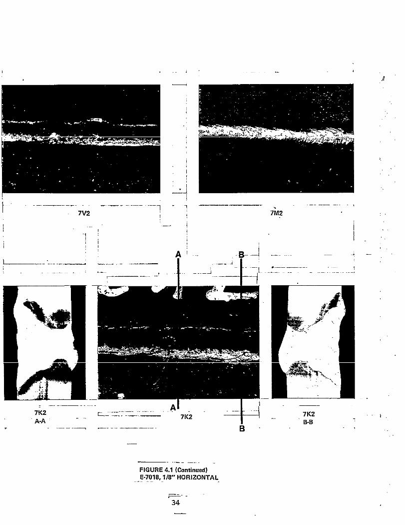
results applicable to all test assemblies. Figure 4.1, "Representa-
tive Back Read Configurations and Cress-Sectional Macrophotographs",
provides a representative sampling of back bead contours and weld
cross sections actually encountered. Figure 4.28 "Longitudinal
Macrophotographs of Stop and Restart Areas", provides information for
certain stopping and restart methods used with ceramic tile backing.
The information accumulated in the evaluatiom program and exhibited
in Table 4.1 and Figures 4.1 and 4.2 permitted evaluation of SMAW in
conjunction with ceramic tile backing with regard to:
● Weld soundness in both run and junction areas
● Back bead contours in both run and junction areas
Weldment toughness, ceramic attaching methods and ceramic neutrality
as specifically relatd to FCAW and SAW processes were investigated
and summarized in an earlier report (Ref. 1) in which no significant
problems were identified. These areas were therefore not specifically
investigated in this evaluation. Although the mailer SMAW puddle
relative to an FCAW or SAW puddle may promote cooling rate differ-
entials and resultant variations in toghness, weld metal toughness
for the half inch thick low carbon steel used in this this and the earlier
evaluation should not vary significantly. Toughness evaluations for
thicker sections and/or
consideration.
As previously mentioned,
crater area resulted in
techniques, based upon
problems in production
caution.
higher strength steels may however warrant
stoping teechniques which did not fill thesporadic centerline crater cracking. Such
data from this evaluation could promote
applications and should be employed with
12

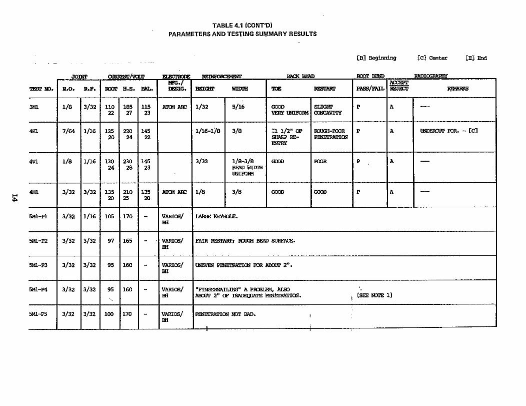


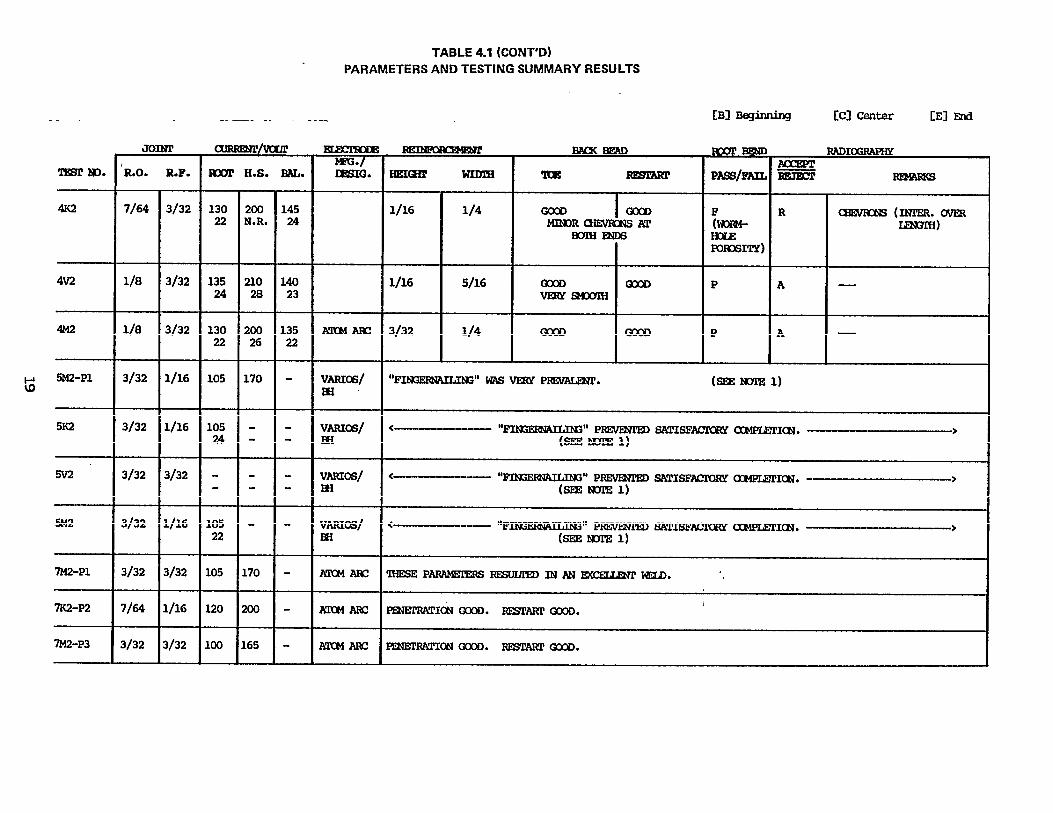


FIGURE 4.1(Index To Figure 4.1)
MACROPHOTO
1K1, 3K1
4K1, 4V1
7K1, 7V1
10K1, 10M1
3M2, 3V2
4K2, 4M2
7K2, 7M2, 7V2
10V2
5V3, 7M3
10K3, 10M3
DESCRIPTION
E7016, 1/8”, FLAT
E7016, 5/32”, FLAT
E7018, 1/8”, FLAT
E7018, 1/8”, FLAT
E601O, 1/8”, FLAT
E7016, 1/8”, HORZ.
E7016, 5/32”, HORZ.
E7018, 1/8”, HORZ.
E6010, 1/8”, HORZ.
E7016, 5/32”, VERT.
E7018, 1/8”, VERT.
E7018, 5/32”, VERT.
E601O, 1/8”, VERT.
PAGE
27
28
29
30
31
32
33
34
35
36
37
38
39
26
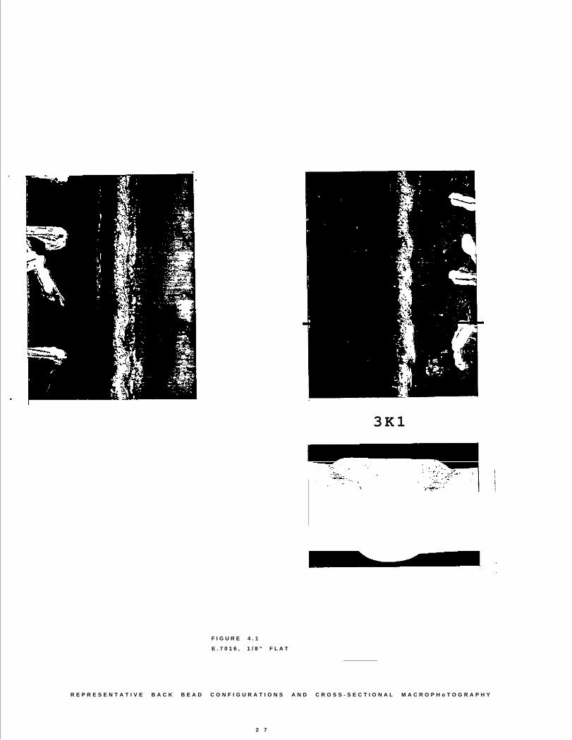
F I G U R E 4 . 1
3K1
E . 7 0 1 6 , 1 / 8 ” F L A T
R E P R E S E N T A T I V E B A C K B E A D C O N F I G U R A T I O N S A N D C R O S S - S E C T I O N A L M A C R O P H o T O G R A P H Y
2 7


30
7 K 1


I


5.0 ANALYSIS
5.1 Back Bead Contours
The use of ceramic
normally resulted in
height - width of
g e n e r a l
tile backing with low hydrogen, one-side SMAW
satisfactory back bead contours as determined by
reinforcement, reentrant angle consistency and
satisfactory back bead contours also resulted
with E601O electrodes. The satisfactory back bead contours obtained
in both non-restart and restart areas with low hydrogen one-side SMAW
over ceramic tile backing were found to be primarily -dependent on
welding technique. Ceramic type was found to have an insignificant
effect on back bead contour while variations due to electrode type
and welding parameters were not significantly different than those
normally encountered without ceramic tile backing.
5.1.1 Back Bead Contours for Non-Restart Areas
The back bead contours for non-restart areas were generally
satisfactory. The principle difficulty was failure to achieve
adequate penetration, a technique-related problem indirectly
related to ceramic tile backing.
With conventional fulll penetration, open root, one-side SMAW,
the welding technique margin for error is extremely narrow.
The welder must strive for adequate penetration via use of
the keyhole technique. However once a keyhole is formed, care
must be exercised to avoid burn-through or puddle breakdown
in which case the force of the arc or gravity overcomes thePuddle's capillary support. For the larger low hydrogen
puddle, the “window” of acceptable technique between inade-
quate penetration and burn-through is quite narrow and
changes of course with Variations in joint geometry obtain-
ing a keyhole is primarily a function of travel speed. A
travel speed too fast will not melt the root faces ahead of
the puddle due to inadequate time. Alternatively, a travel
42
.

speed too slow permits cooler liquid metal to run into the
groove ahead of the puddle. This metal bridges the root
opening rather than melting the root faces. Additional metal.
added as the arc passes, lies atop the bridging metal. The
bridging metal shields the root faces from melting and the
result again is inadequate penetration and a narrow back
bead, as shown in photomacrographs 4K3 and 4Vl of Figure 4.1.
The appropriate travel speed for a given electrode andParameters will vary somewhat with dimensions of the root
faces, root opening and joint mismatch.
In conventional open root, one-side SMAW, if a keyhole is
established and the puddle becomes too large, the puddle can
no longer be held in place by capillarity with the joint
edges and uncontrolled flow occurs. The force of the arc may
push away the molten puddle through opening and
“burn-through” occurs. This has tendency to occur fre-
quently with - hydrogen electrodes due to the large puddle
and occasionally with E601O. Since very fine touch is
required with low hydrogen electrodes to avoid burn-through
on one hand and inadequate penetration on the other, low
hydrogen, open root welding is usually Shunned if an accept-
able alternative exists. With ceramic tile backing, burn-
through is avoided because the ceramic holds the larger
puddle in position for the critical Solidification time. An
experienced welder, however, who remembers previous had
results with low hydrogen, oepn root welding, must develop a
confidence factor when utilizing ceramic tile backing. Fran
prior open root experience, the welder’s first tendency is to
travel too fast with inadequate penetration frequently
resulting.
As mentioned, variations- in joint geometry comlicate the
conventional open root welding operation by necessitating
changes in welding technique as the bead progresses. Since
the margins for error of welding techniques are quite narrow,
43

a very high level of skill and judgment are required to make
appropriate- compensation for changing joint geometries. Joint
variations may occur due to poor initial fitup and/or
narrowing of the root opening ahead of the puddle as the
puddle solidifies and contracts. Shrinkage of the root
opening due to contracting weld metal is controlled in
certain commercial operations by wedging the root opening at
appropriate intervals. The wedges are removed as the bead
approaches them. However fitup variations do occur and some
intermedi“ate contraction ma y occur between wedges. Ceramic
tile backing, by providiq additional puddle support, makes
the one side SMAW process, especially with low hydrogen
electrodes, significantly more forgiving. However unless the
welder develops sufficient confidence in ceramic tile backing
he may “ride” the puddle fearing burn-through if he “key-
holes” . He might thus choose to use hot Start overcome the
resulting lack of penetration. Since other than_ intermittent
use of hot start would overheat the electrode coating, this
is definitely not to be preferred to the keyholing technique.
Intermittent hot start might be justified was was used in
this evaluation for extreme variations in joint fitup,
although a double welded joint might be considered in such
cases. Intermittent use of hot start usually leads to extreme
variation in back bead width.
As mentioned, it was found advantageous to on occassion use the
continuously variable feature of the OPS hot start (i.e. ,
from normal root current to full start current) for areas
other than restart areas. This was sometimes Utilized on
normal run areas where the root opening began to close due to weld solidification contraction, where irregular fitup
resulted in tight root openings or in instances of irregular-ly thick root faces. Such areas would normally begin toresult in lack of penetration if appropriate technique
Changes are not initiated. The welder can obtain extra
current to the degree necessary up to full hot start current
44

to melt through such areas and maintain full penetration. On
photomacrograph 4K3 of Figure 4.1, it appears the back bead
was narrowing as welding progressed. The welder assessed the
condition and turned the hot start on to again achieve full
penetration, taking advantage of the ceramic backing to
support the puddle. On the actual plate (including a portion
not in photograph) it appears this happened twice becomingnarrower the first time while moving off the run-off tab.
Generally, when the root opening began
either terminated t“ he weld or activated
variations in back bead contour with
to close, the welder
the hot start.
respect to electrodetype were observed between the low hydrogen electrodes and
organic coated electrodes. Variations between the E7018 loW
hydrogen iron powder and the E7016 low hydrogen without ironpowder were insignificant. The organic coated E601O elec-
trode, a fast-freeze electrode producing a small puddle,
predictably resulted in noticably different back bead
contours than those achieved with the low hydrogen elec
trodes. There was much less continual effect due to ceramic
tile backing for the E601O electrode, the electrodes seldom
in fact actually melted the ceramic tiles. Flat areas
observed on the back bead, as shown in photomacrographs 10KL
and 10ML (Fig. 4.1), evidenced, however, an occasional needd
for puddle support. The E601O back bead surfaces were
considerably rougher than the surfaces resulting with low
hydrogen electrodes.
5.1.2 Back Bead contours for Restart Areas
The back bead contour for restart areas was generally
satisfactory when utilizing hot starting. Many restart areasho
were almost indistinguishable from the remainder of the bead.
The back bead contour for restart areas was dictated
primarily by restart technique and secondarily by stopping
technique. Principal defects observed were low areas or
45

"gaps" in reinforcement continuity and conversely locally
excessive reinforcement or "bumps". An additional problem was
failure to establish a keyhole at the restart, resulting in a
narrow back bead beginning at the restart area. This was
corrected by the use of hot start short distance
from the restart area once the condition was identified. The
necessity for coordination of electrode travel with the hot
start cycle is evidenced in 4Kl of Fig. 4.1. Optimum penetra-
tion in this instance was not obtained in the restart area.
The bead began to penetrate but travel speed was excessive
and the hot start terminated prematurely. Penetration
decreased and the back bead narrowed. The welder then
reinitiated the hot start and regained full penetration. In
another instance, 4V1 (fig. 4.1) typifies a very narrow
restart area where the crater of the previous stop was not
melted through. Upon restarting, the welder apparently failed
to realize the condition and terminated the hot start prior
to moving off the stop crater from the previous bead. A
keyhole wasn't forming so the welder reinitiated the hot
Start to regain penetration. The series of events in 4Vl and
4KL were similar except that in 4VL, slightly less penetra-
tion was obtained.In both instances, the welder terminated
the hot start prematurely, realized wasn't obtaining
adequate penetration, then reinitiated the hot start as a
corrective measure.
5Kl (Fig 4.1), in the wide back bead area, typifies a good
restart obtained with proper hot-start technique. 4K3
provides an example of an area where ceramic melt occurred at
the restart and did not occur on the prior bead.
5.2 Weld Soundness
The cold starting technique conversely, was found to simply not
possess the "arc drive” necessary to achieve full penetration at
46

restart areas (See 4.2 C & D). As a result, the employment of cold
starting without complete crater taper-grinding is not recommended.
The use of ceramic tile backing with low hydrogen and with E601O
electrodes normally resulted in satisfactory weld metal soundness.
Weld metal soundness was determined by radiographic examination of
each regular test assembly, by root bend testing of each regular test
assembly from a location randomly selected along the approximate 8“
length of weld, and by cross-sectional macrophotography of selected
areas of representative test assemblies. Several additional stop and
restart tests were performed. Relatively few traditional-defects such
as slag, porosity, uudercut, and lack of fusion were detected. The
resultant weld defect rate is considered to be comparable to that
experienced in a similar environment w i t h o u t ceramic backing.
Two defect categories potentially attributable to ceramic tile
backing however, were identified. The first was a chevron porosityand piping problem similar to that encountered previously with FCAW
over ceramic backing. The second was slag inclusions at stop and
restart areas, the frequency of which was quite dependent on welding
technique.
5.2.1 Weld soundness for Non-Restart Areas
Chevron porosity and piping did not occur as frequently
with SMAW as it did with FCAW (Ref. 1). The option of
placing the arc at the center or at the leading edge of the
puddle to achieve a satisfactory back bead contour however,
does not exist with SMAW as it did with FCAW. The leading
edge of the SMAW puddle is not hot enough to melt the root
faces and thereby obtain full penetration unless the SMAW
arc is directly over it.
Disregarding the beginning and end effects of the run-off
tabs (usually piping existed there), Chevron porosity
and/or piping (as distinguished from other porosity)
47

existed in one flat position plate (3M1-P3 ), seven hori-
zontal position plates ( 3M2, 4M2-P1, 4M2-P2, 4M2-P3,
4M2-P4, 4K2, 7K2) and in no vertical position plates. The
absence of Chevron porosity and piping in vertical positio n
SMAW plates is consistent with FCAW results. Apparently the
vertical welds with SMAW, as with FCAW, vent any disolved
gases upward and out of the puddle relatively unrestricted.
As shown in photomacrographs 3M2 and 4K2 of Figure 4.1, the
chevron porosity and piping which occurred in the horizon-
tal position plates was always in the upper half of the
weld section, adding further support to the theory that
dissolved gases rise and become trapped upon weld metal
solidification. No other soundness problems were identified
in non-restart areas. Test assembly 10M3 root bend frac-
tured due to a brittle zone which appeared to be in the
second pass. It does not appear related to ceramic backing.
5.2.2 Weld Soundness for Restart Areas
In restart areas, chevron porosity was found to be non-
existent. Non-chevron (traditional) porosity warrantingrejection to the radiography requirements of ABS and/or
NAVSHIPS occurred only in plates IK3 and 4M3. It is
assumed that this occurrence rate is well.within the realm
of normal frequency and is not attributable to ceramic
backing.
Restart areas were otherwise generally sound but were
occasionally plagued by slag inclusions or pockets appar-
ently inherent to low hydrogen electrodes over ceramic
backing. An interesting disclosure from the further
investigation identified in 3.2 was the formation of a slag
pocket under the end of some stop craters. This phenomenon,
having the appearance of liquid slag rolled beneath the
weld puddle and entrapped prior to puddle solidification
is depicted in Fig. 4.2B. The crater slag pockets were
48

found to exist inherently open to the root bead back side
and are assumed to be attached to the ceramic "under-slag”
upon solidification. It further suggested from this
evaluation and from investigation by others(ref. 2), that
the under-bead crater slag phenomenon is potentially acommon occurrence with low hydrogen SMAW over Ceramic
backing regardless of the stopping techniques employed.
Although their presence is assumed likely in low hydrogen
ceramic backing applications, tier-bead crater slag
inclusions by virtue of location cannot be detected from
the working side. The awareness, however, of their likli-
hood was found beneficial in rectifying the inclusion
phenomenon through employment of the hot start re-technique. With hot start, the necessary heat is
available to remelt weld metal encompassing the entrappedslag, to remelt the entrapped slag (or at least the “neck”
to detach it), and to provide the slag Sufficient time to
float out of the puddle prior to re-solidification. A
conventional cold start technique, as indicated in the
longitudinal section results (see Fig. 4.2C), does not
begin to accomplish this necessary criteria. Cold start
remelting, as suggested by numerous macrophotos, would
normally penetrate only the top periphery of the slag
pocket.
The cold start technique used in conjunction with complete
crater taper-grinding although not a major scope consider-ation in this evaluation, would have possible merit in
certain production applications. It is opinions that such
a combination would perhaps decrease the occurrence of
crater slag inclusions in completed welds, but at the same
time have a quite negative impact on cost effectiveness.
Within the stop of this investigation, slag inclusions
were identified by radiography on plates lMl, 1OM2, lM3,
49

3M3, 4M3, 7V3, 8K3, 8M3 and 10K3. The only plates in which
it was severe enough to warrantnt rejection to ABS and/or
NAVSHIPS were 10M2 and 4M3. Since 10M2 was welded with an
E601O electrode in which the ceramic backing had no
significant effect in forming the weld bead, that slag is
probably unrelated to ceramic tile backing. The rejectable
slag inclusion in plate 4M3 might be related to ceramic
backing. One rejectable slag inclusion with low hydrogen
electrode over ceramic backing out of fifty-four such
plates is witin an acceptable frequency range. It must beremembered however, that these statistics are derived from
resultant data in Which the majority of terminal craters
were neither conventionally filled nor taper-ground. In
production applications, as previously stated, conventional
filling techniques may be required as a means of
controlling crater cracking. With the fuller conventional
crater of less inherent taper, taper-grinding prior to hot
starting may be required as necessary to effectively
minimize the occurance of entrapped root crater slag.
50

6.0 SIGNIFICANT CONCLUSION_ AND RECOMMENDATIONS
Ceramic tile backing in conjunction with was found to be
beneficial with both low hydrogen and organic type electrodes. For
low hydrogen open root welding (for situations where this combination
is essential) ceramic tile backing essential makes this process
possible. By providing puddle support for the large, fluid lowhydrogen puddles ceramic tile backing brought a process normally used
only by the extremely skilled welder into the realm of capability of
the average welder. For organic type coatings in open root welding
applications, the use of ceramic tile backing appeared to greatly
reduce the reject rate. Although puddle support is not required with
organic coated electrodes to the degree it is with low hydrogen
electrodes, ceramic tile backing, by providing that puddle support at
the intermittent tires it is needed, reduces the historic defect rate
obtained with organic coated electrodes.
The two significant problems occurring
chevron porosity and piping and slag
areas, were found necessary to address.
with ceramic tile backing,
inclusions at step/restart
chevron porosity and piping
Occurred most frequently in the horizontal position. It did not occur
as frequently as it did with FCAW. The slag pockets at stop and
restart areas usually occurred with the heavy slagging, low hydrogen
electrodes and appears inherently related to the slag from the melted
ceramic tile. Stopping and restart techniques Which provide suffi-
cient penetration to melt around the slag pocket and the pocket
itself together with enough time to float out the melted slag are
essential. Such stopping and restart techniques exist and are
operationally Possible. Hot start is an essential part of the
necessary restart techniques. Hot start could also be used inter-
mittently for bead shape purposes rather than removal of slag
pockets, however appropriate welding techniques made possible by
ceramic tile backing should render-this unnecessary in anything but
extreme cases.
51

Ceramic tile backing is recommended on the basis of these evaluation
results for all low hydrogen, open root welding and for critical
applications involving organic coated electrodes with open root
joints. Hot start and appropriate manipulation techniques are usuallynecessary to prevent slag inclusions at stop and restart areas.
Awareness of the possibility of chevron porosity and piping, espe-
cially in the horizontal position, must be addressed. Stringent
Welder training to develop a confidence factor to utilize “Keyhole”
techniques not previously possible without ceramic tile backing
should, as a rule, eliminate the need to employ hot start in other
than start areas, but hot start could be used as necessary to obtain
appropriate bead shape.

7.0 REFERENCES
1. Bahlow, T. E., Cantrell, R. E., and St. Pierre, D. J.; June 1980“ceramic Weld Backing Evaluation”, MARAD SNAME SP-7 WeldingPanel.
2. Blamquist, P.A.; July 1981; “Hot Start - The Key to SuccessfulSMA Welding With Ceramic Backing”; Welding Journal.