Offshore Pipeline Technology – Challenges & Solutions Nick Brown... ·...
38
LISTENS…DELIVERS…EVOLVES. Offshore Pipeline Technology – Challenges & Solutions Nick Brown
Transcript of Offshore Pipeline Technology – Challenges & Solutions Nick Brown... ·...
LISTENS…DELIVERS…EVOLVES.
Offshore Pipeline Technology – Challenges & Solutions
Nick Brown
LISTENS.
Presentation Contents
• Review of Key Subsea Pipeline Technology Drivers– Frontier oil & gas development drivers– Environmental drivers
• Technical Challenges: Continental Shelf-break Crossings– Crossing of steep & rugged seabeds– Geohazards
• Technical Challenges: HP/HT developments– Pipelines protected by Instrumented over-pressure protection systems – Management of Lateral buckling
• Technical Challenges: Environment– Cryogenic offloading pipelines– Pipeline stabilisation innovations
LISTENS.
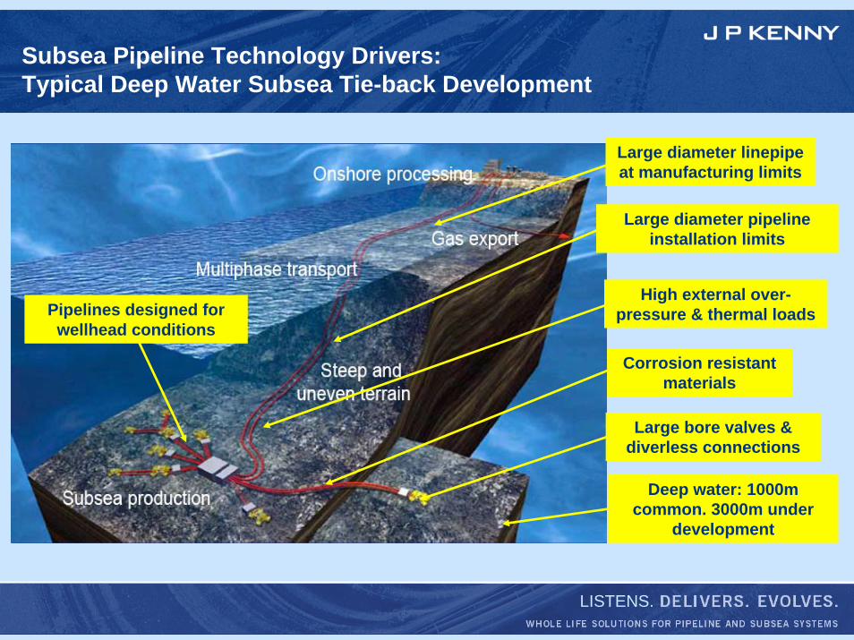
Subsea Pipeline Technology Drivers:Typical Deep Water Subsea Tie-back Development
Large diameter pipeline installation limits
High external over-pressure & thermal loads
Corrosion resistant materials
Large bore valves & diverless connections
Large diameter linepipeat manufacturing limits
Deep water: 1000m common. 3000m under
development
Pipelines designed for wellhead conditions
LISTENS.
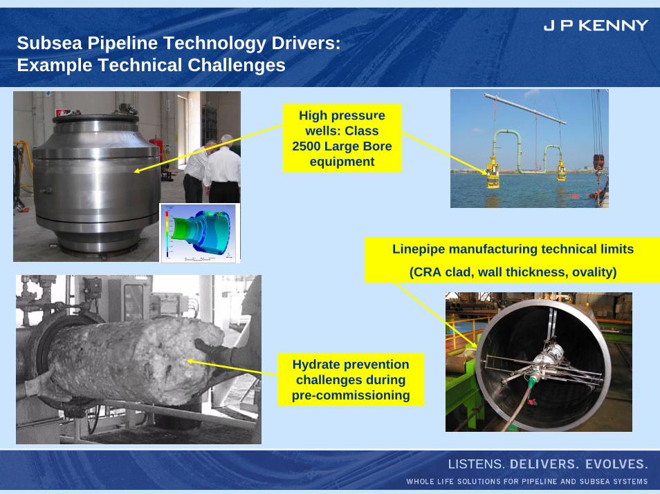
Subsea Pipeline Technology Drivers:Example Technical Challenges
Hydrate prevention challenges during
pre-commissioning
High pressure wells: Class
2500 Large Bore equipment
Linepipe manufacturing technical limits
(CRA clad, wall thickness, ovality)
LISTENS.
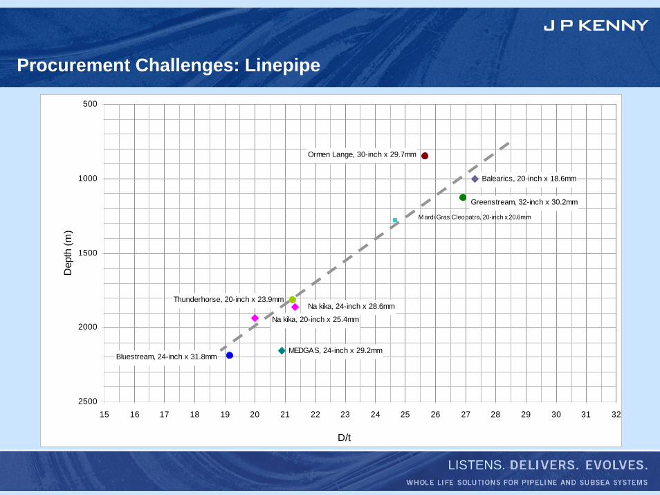
Procurement Challenges: Linepipe
Bluestream, 24-inch x 31.8mm
Na kika, 20-inch x 25.4mm
Na kika, 24-inch x 28.6mm
Greenstream, 32-inch x 30.2mm
Ormen Lange, 30-inch x 29.7mm
Thunderhorse, 20-inch x 23.9mm
Balearics, 20-inch x 18.6mm
MEDGAS, 24-inch x 29.2mm
M ardi Gras Cleopatra, 20-inch x 20.6mm
500
1000
1500
2000
250015 16 17 18 19 20 21 22 23 24 25 26 27 28 29 30 31 32
D/t
Dep
th (m
)

LISTENS.
Installation Challenges
Deep water pipelay
Deep water excavation
Deep water rock dump
LISTENS.
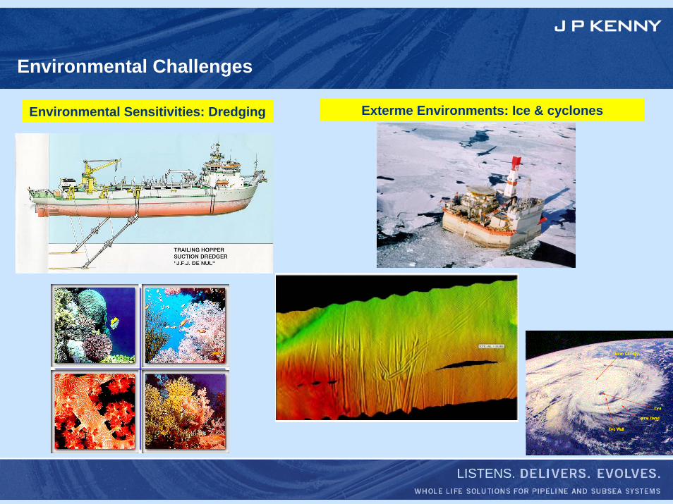
Environmental Challenges
Environmental Sensitivities: Dredging Exterme Environments: Ice & cyclones
LISTENS.
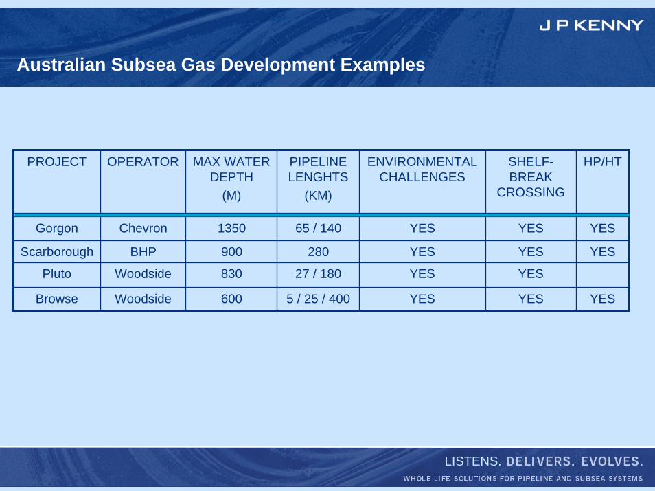
Australian Subsea Gas Development Examples
PROJECT OPERATOR MAX WATER DEPTH
(M)
PIPELINE LENGHTS
(KM)
ENVIRONMENTAL CHALLENGES
SHELF-BREAK
CROSSING
HP/HT
Gorgon Chevron 1350 65 / 140 YES YES YES
Scarborough BHP 900 280 YES YES YES
Pluto Woodside 830 27 / 180 YES YES
Browse Woodside 600 5 / 25 / 400 YES YES YES
LISTENS.
CONTINENTAL SHELF-BREAK PIPELINE CROSSINGS
1. Crossing of steep & rugged seabeds2. Geohazards
LISTENS.
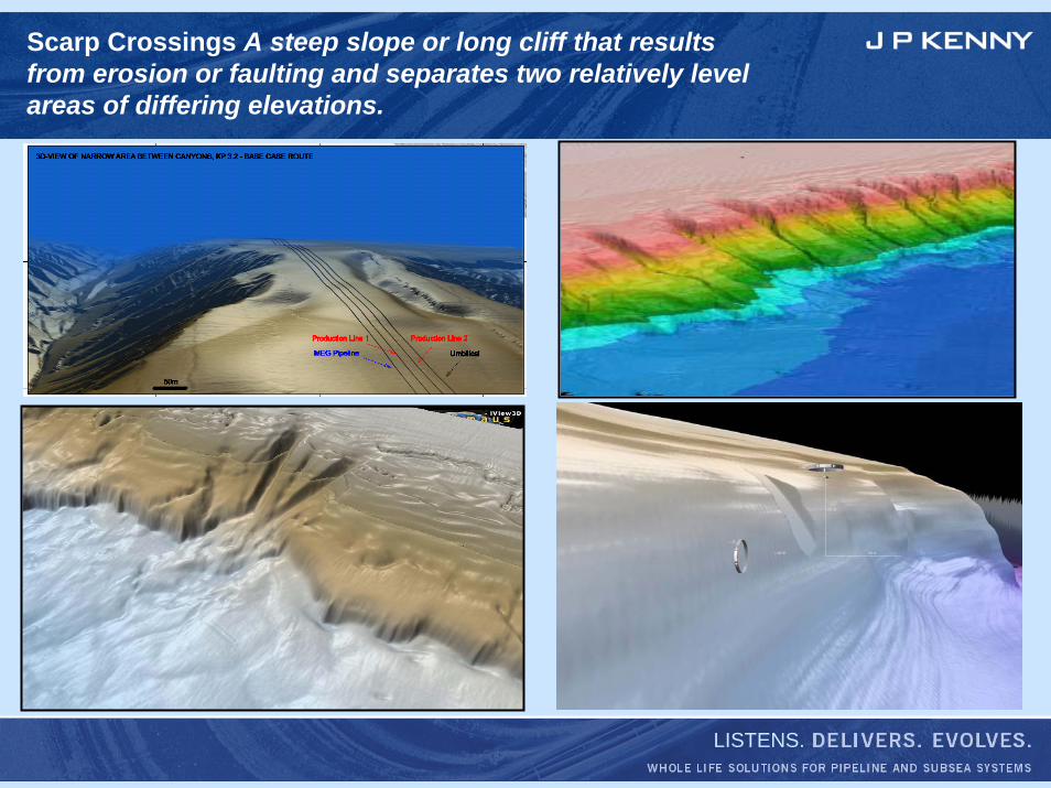
Scarp Crossings A steep slope or long cliff that results from erosion or faulting and separates two relatively level areas of differing elevations.
LISTENS.
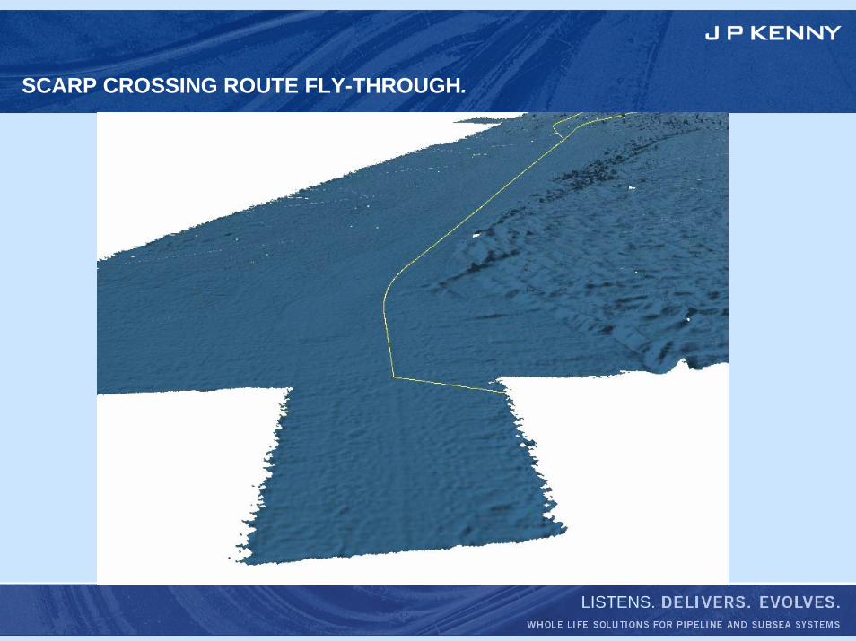
SCARP CROSSING ROUTE FLY-THROUGH.
LISTENS.
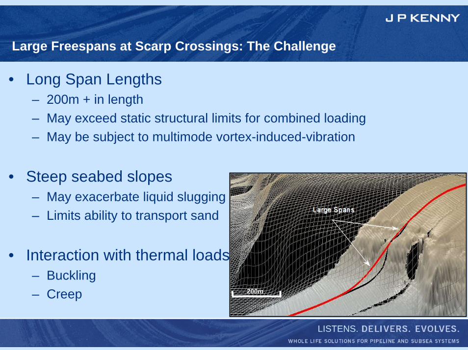
Large Freespans at Scarp Crossings: The Challenge
• Long Span Lengths– 200m + in length– May exceed static structural limits for combined loading– May be subject to multimode vortex-induced-vibration
• Steep seabed slopes– May exacerbate liquid slugging– Limits ability to transport sand
• Interaction with thermal loads– Buckling– Creep 200m200m
LISTENS.
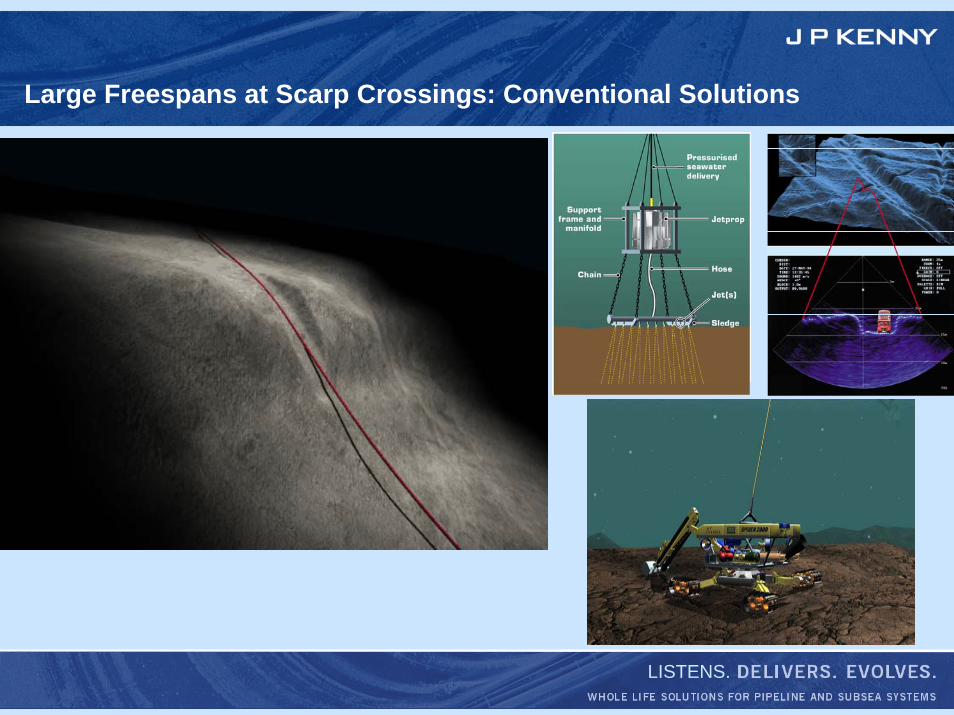
Large Freespans at Scarp Crossings: Conventional Solutions
LISTENS.
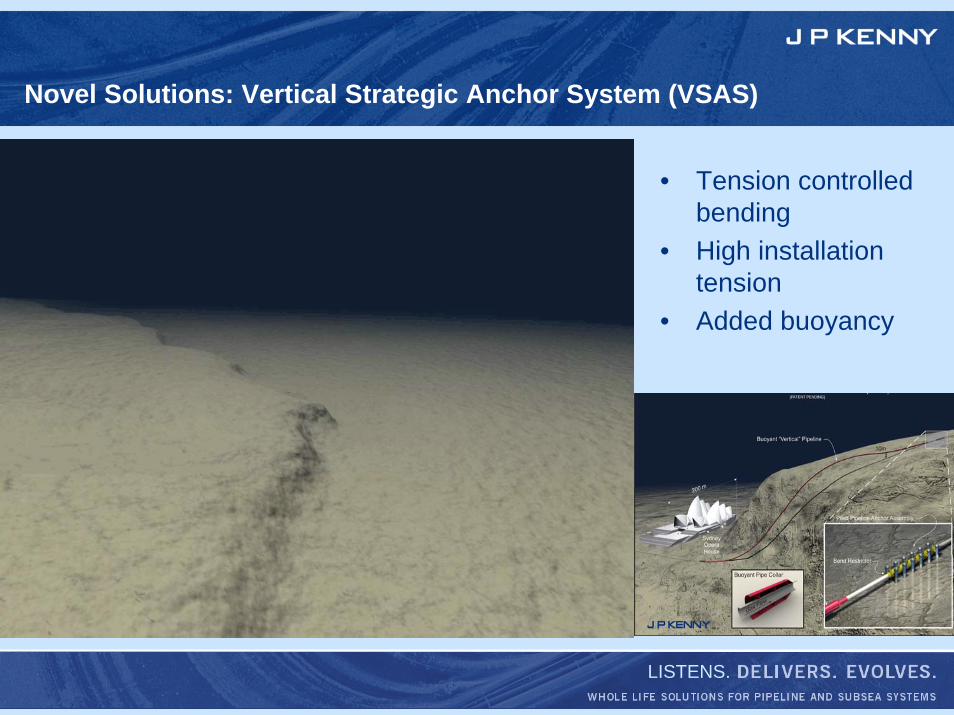
Novel Solutions: Vertical Strategic Anchor System (VSAS)
• Tension controlled bending
• High installation tension
• Added buoyancy
LISTENS.
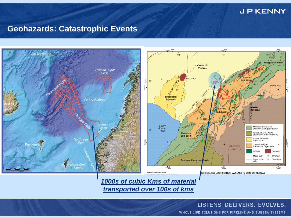
Geohazards: Catastrophic Events
1000s of cubic Kms of material transported over 100s of kms
LISTENS.
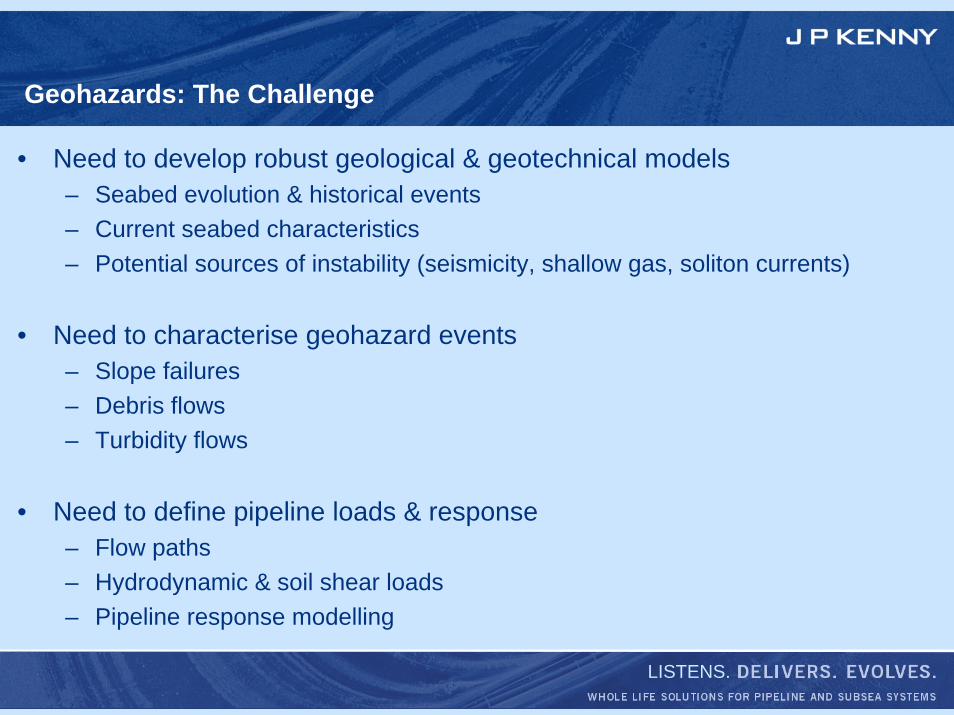
Geohazards: The Challenge
• Need to develop robust geological & geotechnical models– Seabed evolution & historical events– Current seabed characteristics– Potential sources of instability (seismicity, shallow gas, soliton currents)
• Need to characterise geohazard events– Slope failures– Debris flows– Turbidity flows
• Need to define pipeline loads & response– Flow paths– Hydrodynamic & soil shear loads– Pipeline response modelling
LISTENS.
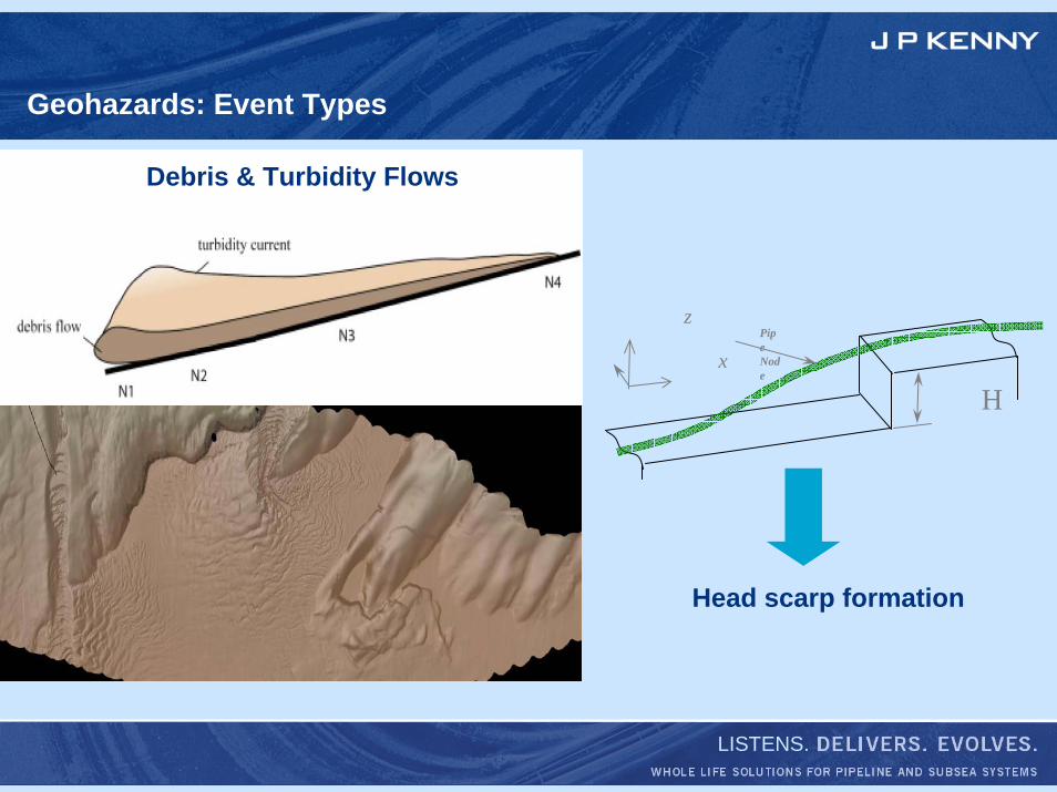
Geohazards: Event Types
Hx
zPipe Node
Head scarp formation
Debris & Turbidity Flows
LISTENS.
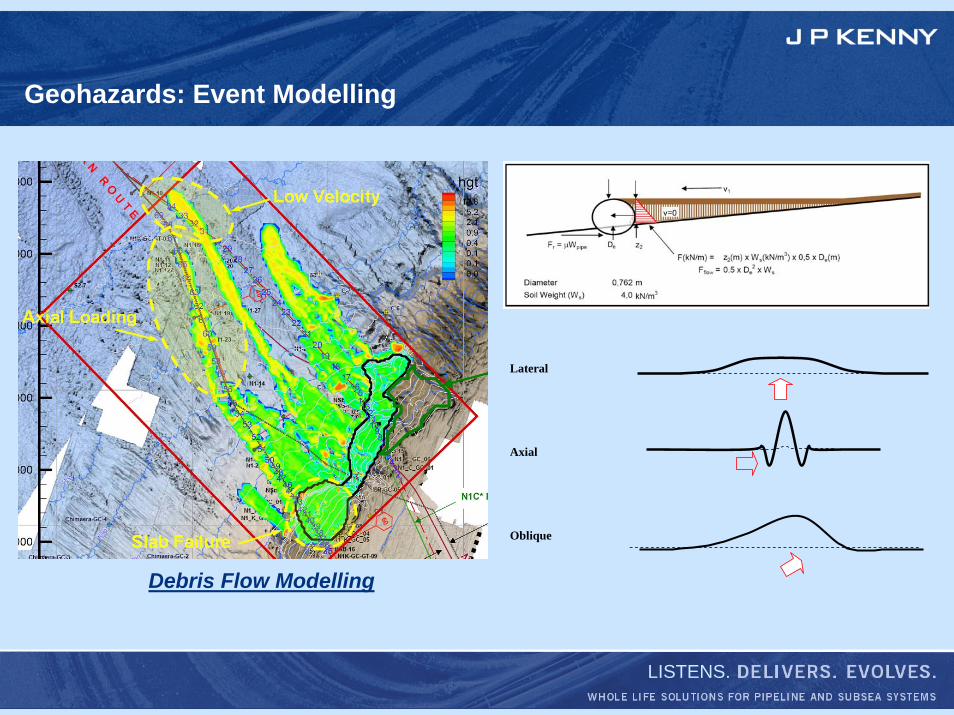
Geohazards: Event Modelling
Debris Flow Modelling
Lateral Axial Oblique
LISTENS.
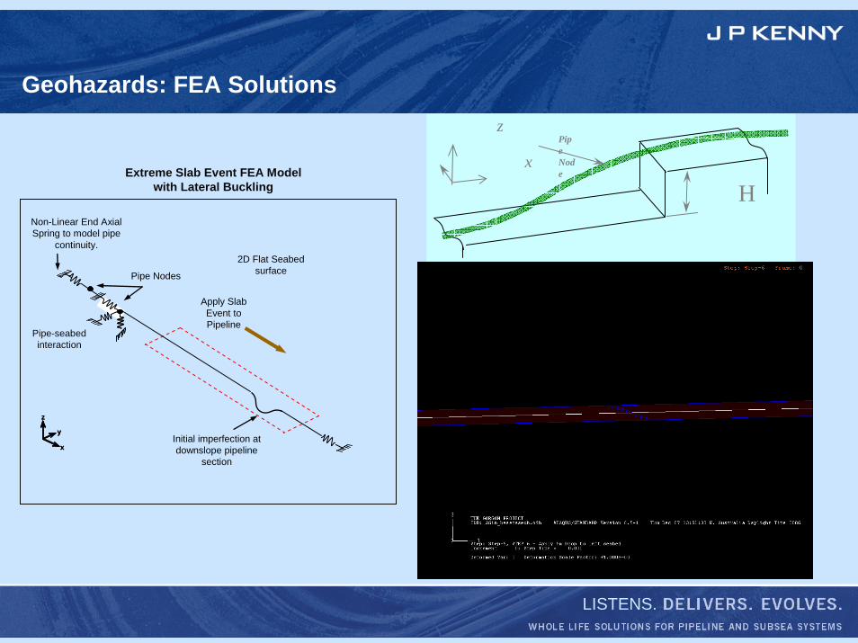
Geohazards: FEA Solutions
Non-Linear End Axial Spring to model pipe
continuity.2D Flat Seabed
surface
x
y
z
x
y
z
Initial imperfection at downslope pipeline
section
Pipe Nodes
Pipe-seabed interaction
Seabed Surface Displacement
2L1
L1
Effective Axial ForceμWs × ½ L1
(max)
Extreme Slab Event FEA Model with Lateral Buckling
δApply Slab Event to Pipeline
Debris Flow Modelling
Hx
zPipe Node
LISTENS.
HIGH PRESSURE / HIGH TEMPERATURE RESERVOIRS
1. Application of Instrumented Over-pressure Protection Systems2. Pipeline Buckling
LISTENS.
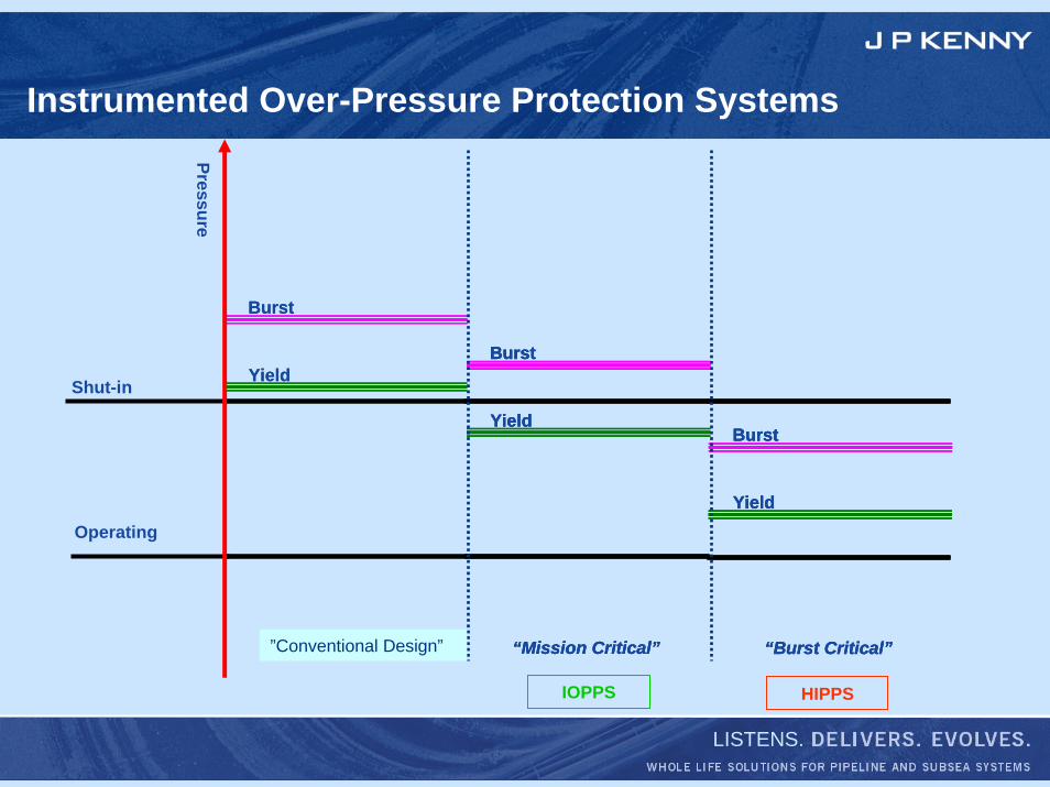
Instrumented Over-Pressure Protection Systems
Burst
Yield
“Code Compliant”
Burst
Yield
“Code Compliant” “Mission Critical”
Burst
Yield
“Mission Critical”
Burst
Yield
“Mission Critical”
Burst
Yield
“Burst Critical”
Burst
Yield
“Burst Critical”
Burst
Yield
“Burst Critical”
Burst
Yield
Shut-in
Operating
Pressure
IOPPS HIPPS
”Conventional Design”
LISTENS.
Instrumented Over-pressure Protection Systems: The Challenge
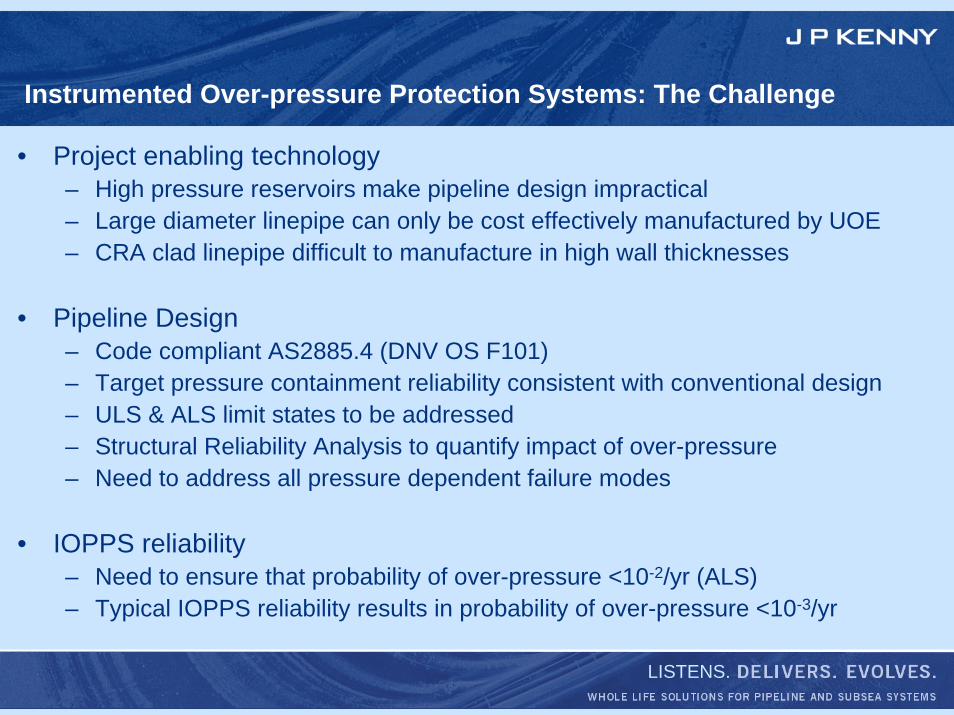
• Project enabling technology– High pressure reservoirs make pipeline design impractical– Large diameter linepipe can only be cost effectively manufactured by UOE– CRA clad linepipe difficult to manufacture in high wall thicknesses
• Pipeline Design– Code compliant AS2885.4 (DNV OS F101)– Target pressure containment reliability consistent with conventional design– ULS & ALS limit states to be addressed– Structural Reliability Analysis to quantify impact of over-pressure– Need to address all pressure dependent failure modes
• IOPPS reliability– Need to ensure that probability of over-pressure <10-2/yr (ALS)– Typical IOPPS reliability results in probability of over-pressure <10-3/yr
LISTENS.
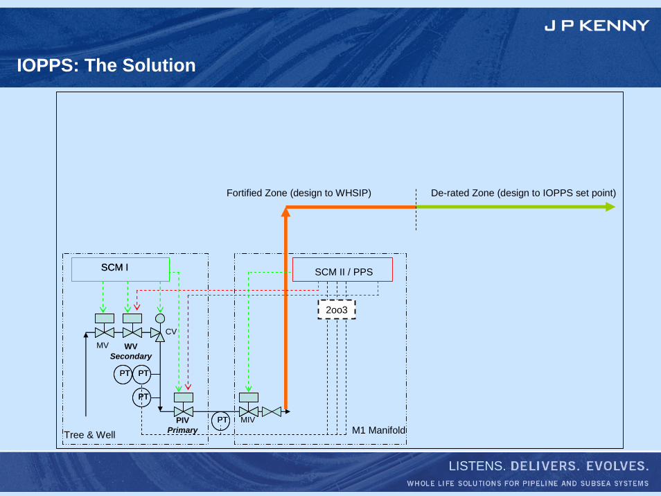
IOPPS: The Solution
M1 Manifold
SCM ISCM I
MV
Tree & Well
WVSecondary
PIVPrimary
MIV
CV
PTPTPTPT
PTPT
PTPT
SCM II / PPS
2oo3
Fortified Zone (design to WHSIP) De-rated Zone (design to IOPPS set point)
LISTENS.
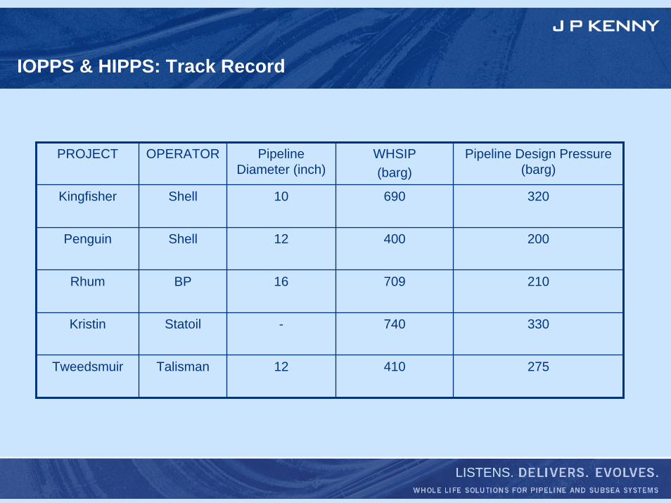
IOPPS & HIPPS: Track Record
PROJECT OPERATOR Pipeline Diameter (inch)
WHSIP(barg)
Pipeline Design Pressure (barg)
Kingfisher Shell 10 690
400
709
740
410
320
Penguin Shell 12 200
Rhum BP 16 210
Kristin Statoil - 330
Tweedsmuir Talisman 12 275
LISTENS.
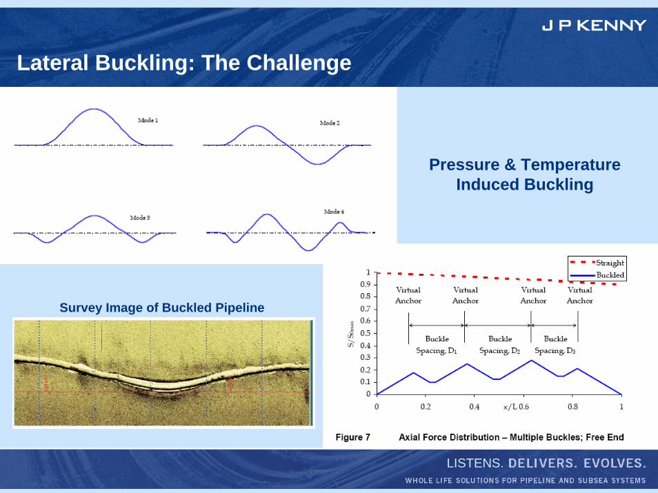
Lateral Buckling: The Challenge
Pressure & Temperature Induced Buckling
Survey Image of Buckled Pipeline
LISTENS.
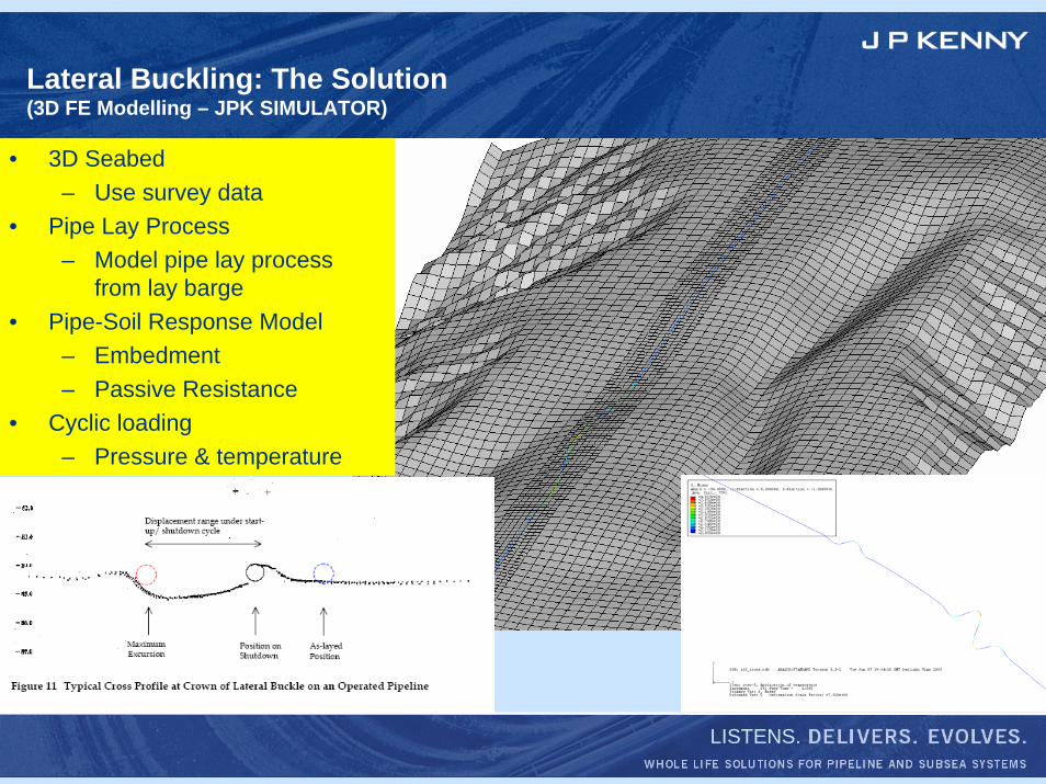
Lateral Buckling: The Solution(3D FE Modelling – JPK SIMULATOR)
• 3D Seabed– Use survey data
• Pipe Lay Process– Model pipe lay process
from lay barge• Pipe-Soil Response Model
– Embedment– Passive Resistance
• Cyclic loading– Pressure & temperature
LISTENS.
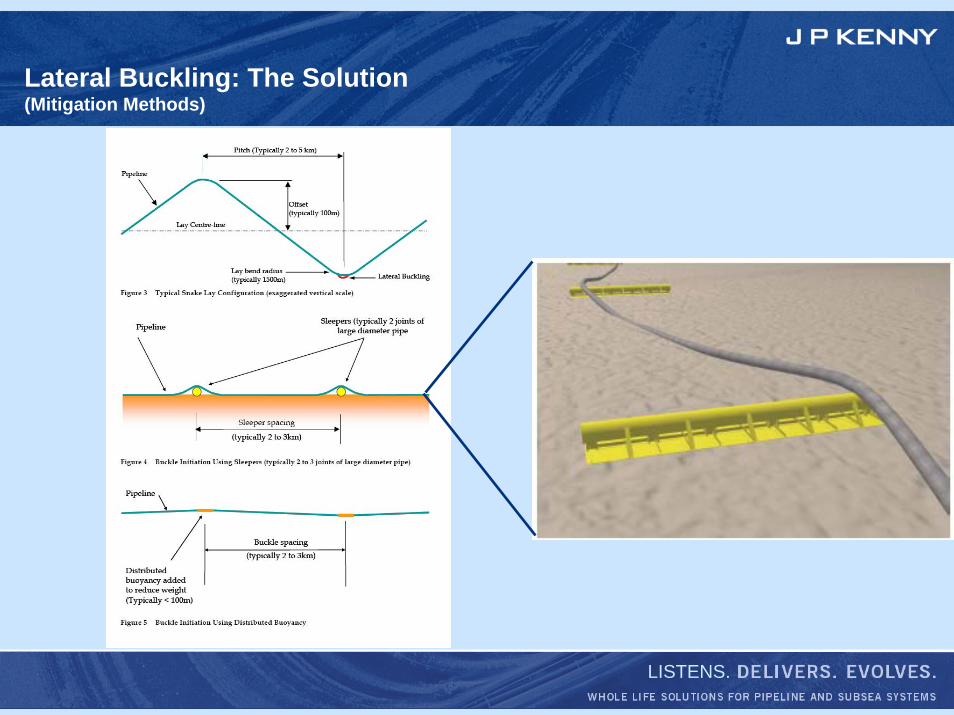
Lateral Buckling: The Solution(Mitigation Methods)
LISTENS.
ENVIRONMENTAL CHALLENGES
1. Application of Cryogenic Pipelines2. North West Shelf Pipeline Stabilisation
LISTENS.
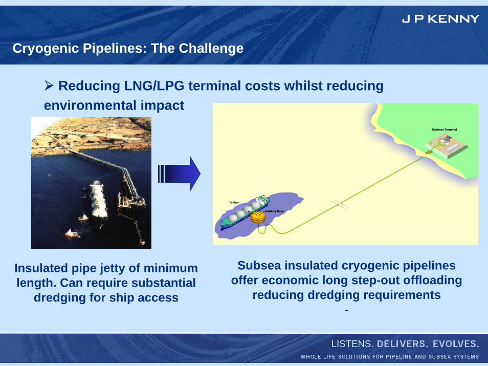
Insulated pipe jetty of minimum length. Can require substantial
dredging for ship access
Reducing LNG/LPG terminal costs whilst reducingenvironmental impact
Subsea insulated cryogenic pipelinesoffer economic long step-out offloading
reducing dredging requirements-
Cryogenic Pipelines: The Challenge
LISTENS.
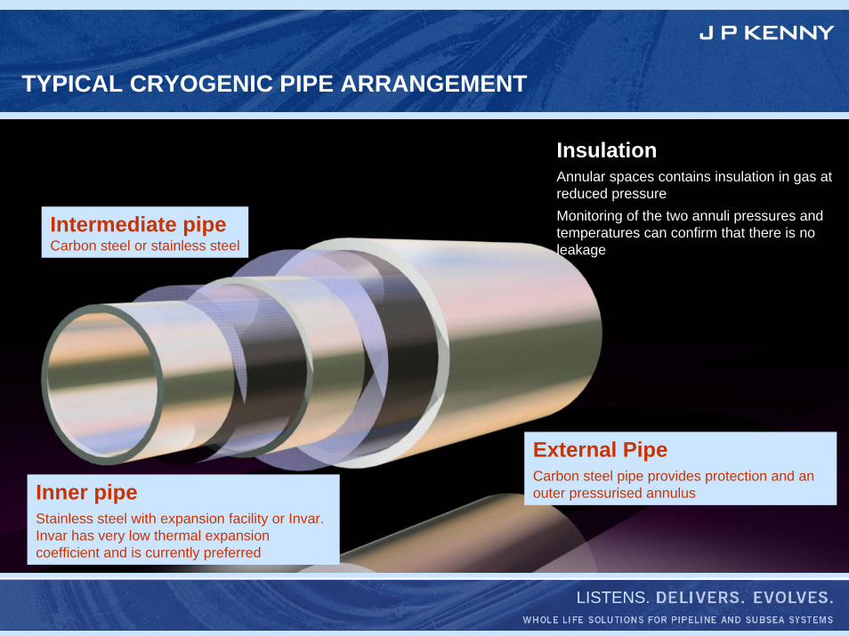
TYPICAL CRYOGENIC PIPE ARRANGEMENT
InsulationAnnular spaces contains insulation in gas at reduced pressureMonitoring of the two annuli pressures and temperatures can confirm that there is no leakage
External PipeCarbon steel pipe provides protection and an outer pressurised annulusInner pipe
Stainless steel with expansion facility or Invar. Invar has very low thermal expansion coefficient and is currently preferred
Intermediate pipeCarbon steel or stainless steel
LISTENS.
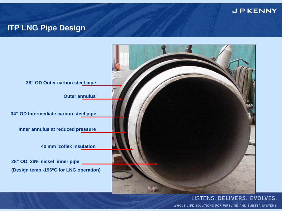
ITP LNG Pipe Design
38” OD Outer carbon steel pipe
Outer annulus
34” OD Intermediate carbon steel pipe
Inner annulus at reduced pressure
40 mm Izoflex insulation
28” OD, 36% nickel inner pipe
(Design temp -196oC for LNG operation)
LISTENS.
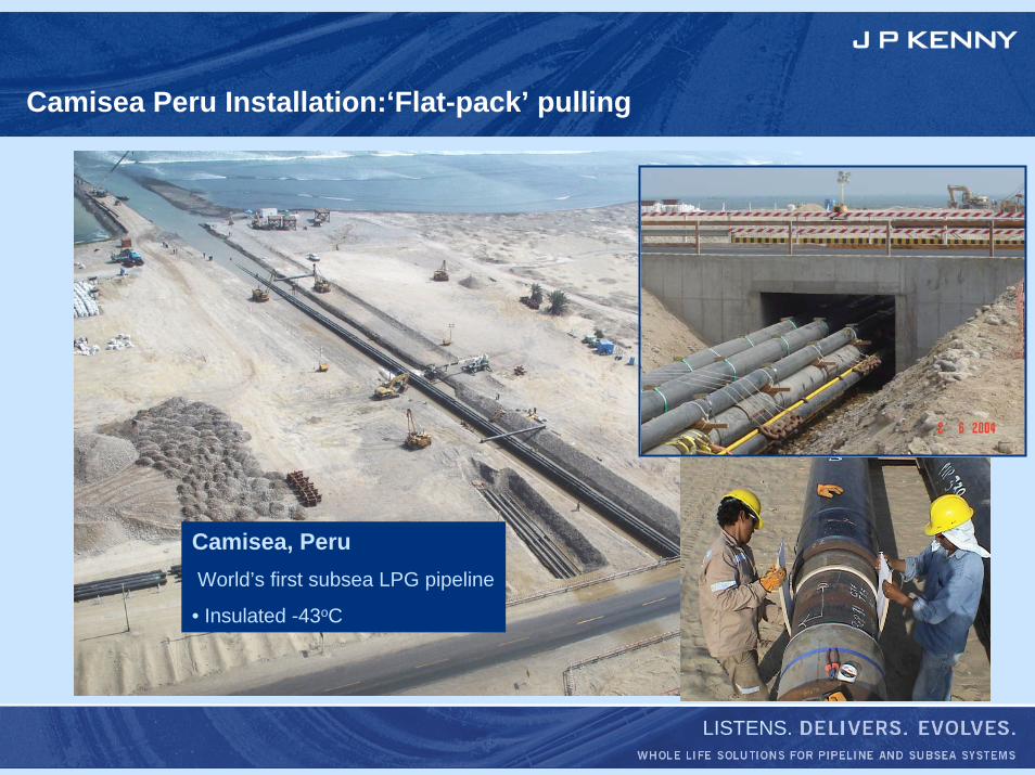
Camisea Peru Installation:‘Flat-pack’ pulling
Camisea, PeruWorld’s first subsea LPG pipeline
• Insulated -43oC
LISTENS.
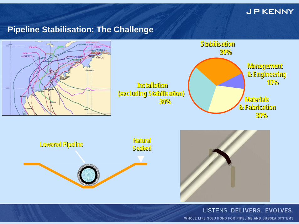
Pipeline Stabilisation: The Challenge
Materials Materials & Fabrication& Fabrication
30%30%
Management Management & Engineering& Engineering
10%10%
StabilisationStabilisation30%30%
InstallationInstallation(excluding Stabilisation)(excluding Stabilisation)
30%30% Materials Materials & Fabrication& Fabrication
30%30%
Management Management & Engineering& Engineering
10%10%
StabilisationStabilisation30%30%
InstallationInstallation(excluding Stabilisation)(excluding Stabilisation)
30%30%
Lowered PipelineLowered Pipeline Natural Natural SeabedSeabedLowered PipelineLowered Pipeline Natural Natural SeabedSeabed
LISTENS.
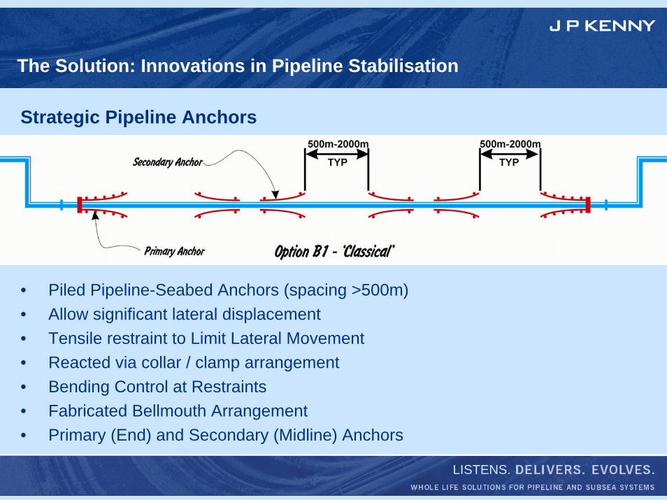
The Solution: Innovations in Pipeline Stabilisation
Strategic Pipeline Anchors
• Piled Pipeline-Seabed Anchors (spacing >500m)• Allow significant lateral displacement• Tensile restraint to Limit Lateral Movement• Reacted via collar / clamp arrangement• Bending Control at Restraints• Fabricated Bellmouth Arrangement• Primary (End) and Secondary (Midline) Anchors
LISTENS.
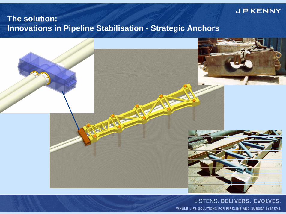
The solution:Innovations in Pipeline Stabilisation - Strategic Anchors
LISTENS.
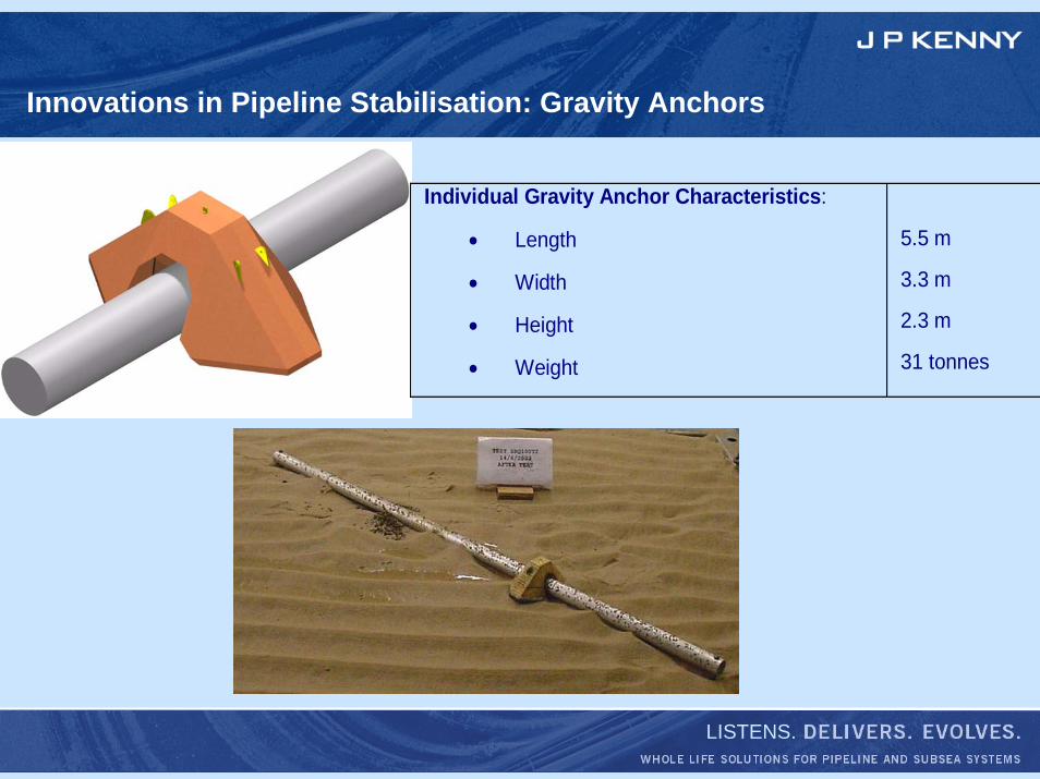
Innovations in Pipeline Stabilisation: Gravity Anchors
Individual Gravity Anchor Characteristics:
• Length
• Width
• Height
• Weight
5.5 m
3.3 m
2.3 m
31 tonnes
LISTENS.
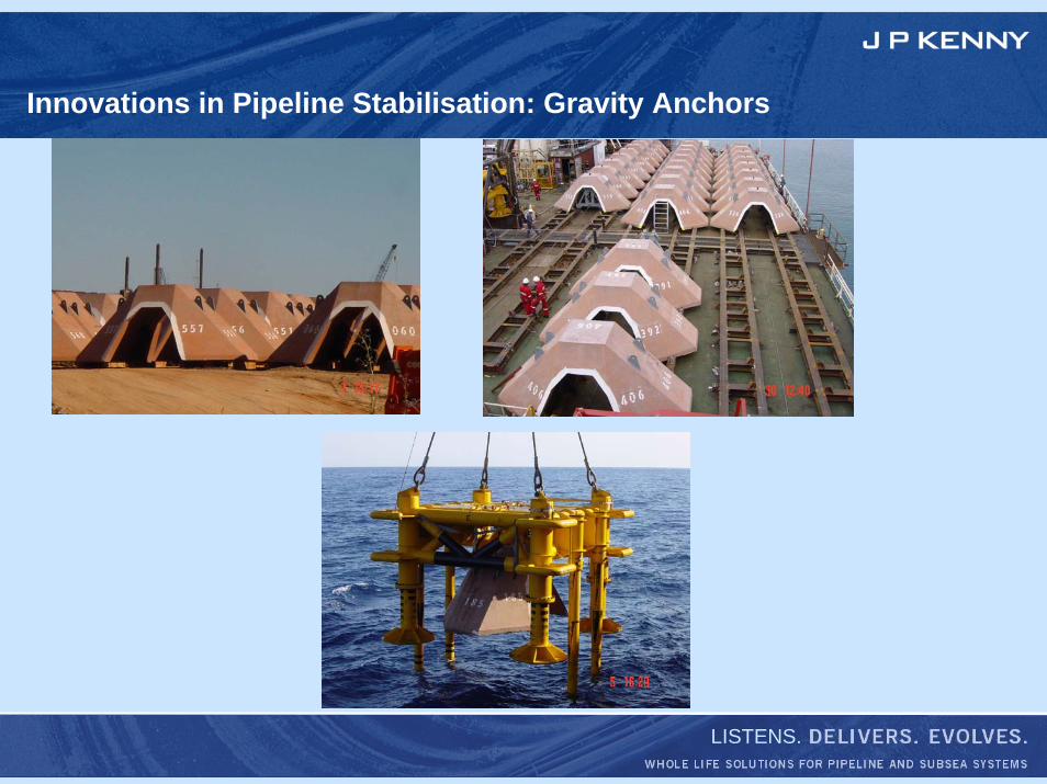
Innovations in Pipeline Stabilisation: Gravity Anchors
LISTENS.
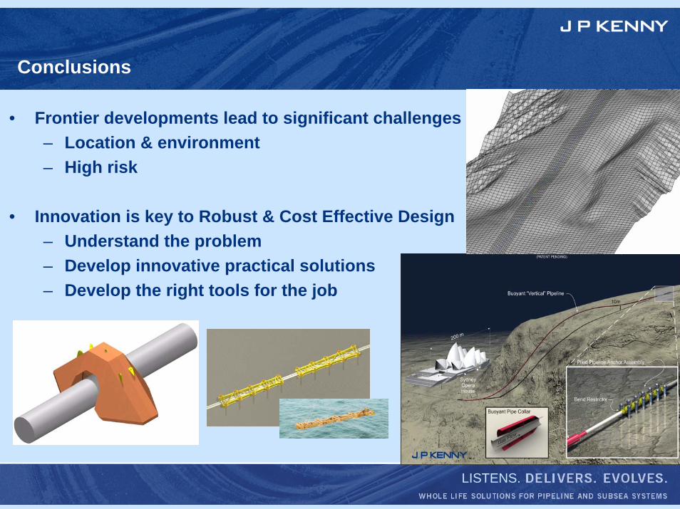
Conclusions
• Frontier developments lead to significant challenges– Location & environment– High risk
• Innovation is key to Robust & Cost Effective Design– Understand the problem– Develop innovative practical solutions– Develop the right tools for the job