OFFSHORE MOORING CHAIN...Foreword. Foreword . This is the fourth edition of the . Guide for the...
55
Guide for the Certification of Offshore Mooring Chains GUIDE FOR THE CERTIFICATION OF OFFSHORE MOORING CHAIN MAY 2017 American Bureau of Shipping Incorporated by Act of Legislature of the State of New York 1862 2017 American Bureau of Shipping. All rights reserved. ABS Plaza 16855 Northchase Drive Houston, TX 77060 USA
Transcript of OFFSHORE MOORING CHAIN...Foreword. Foreword . This is the fourth edition of the . Guide for the...

G u i d e f o r t h e C e r t i f i c a t i o n o f O f f s h o r e M o o r i n g C h a i n s
GUIDE FOR THE CERTIFICATION OF
OFFSHORE MOORING CHAIN
MAY 2017
American Bureau of Shipping Incorporated by Act of Legislature of the State of New York 1862
2017 American Bureau of Shipping. All rights reserved. ABS Plaza 16855 Northchase Drive Houston, TX 77060 USA
F o r e w o r d
Foreword This is the fourth edition of the Guide for the Certification of Offshore Mooring Chain, following from the 1986, 1999 and 2009 versions.
Based on IACS UR W22, this new version adds requirements for thimbles, introduces qualification of higher grades to cover lower grades, and includes more detail on CTOD tests, furnace calibration, guidance on failed proof load tests, and more detail on NDE.
This Guide supersedes previous versions and ABS encourages its immediate application. Compliance with this edition is required for offshore units and single point moorings contracted for construction on or after 1 July 2017 and when the application for certification of chains and accessories is dated on or after 1 July 2017.
Users are advised to check periodically on the ABS website www.eagle.org to verify that this version of this Guide is the most current.
We welcome your feedback. Comments or suggestions can be sent electronically by email to [email protected].
ii ABS GUIDE FOR THE CERTIFICATION OF OFFSHORE MOORING CHAIN . 2017

T a b l e o f C o n t e n t s
GUIDE FOR THE CERTIFICATION OF
OFFSHORE MOORING CHAIN
CONTENTS SECTION 1 General Requirements ........................................................................... 1
1 Scope .................................................................................................. 1 1.1 Application ....................................................................................... 1 1.3 Mooring Equipment ......................................................................... 1 1.5 Studless Chain ................................................................................ 1 1.7 Chafing Chain .................................................................................. 1 1.9 Special Subsea Mooring Connectors .............................................. 1
3 Chain and Accessory Grades ............................................................. 2 3.1 R3, R3S, R4, R4S, and R5 .............................................................. 2 3.3 R4S and R5 ..................................................................................... 2 3.5 Approval .......................................................................................... 2
5 Chain Manufacturer Approval ............................................................. 3 5.1 Approval of Chain Manufacturers .................................................... 3 5.3 Manufacturing Process Approval ..................................................... 3 5.5 CTOD Tests (Crack Tip Opening Displacement Tests) ................... 3 5.7 Furnace Calibration ......................................................................... 4 5.9 R4S and R5 Additional Requirements ............................................. 4 5.11 Qualification Testing ........................................................................ 5
7 Approval of Quality Systems at Chain Manufacturers and Bar Producers ............................................................................................ 6 7.1 Quality Provision ............................................................................. 6 7.3 Procedures for Obtaining Approval ................................................. 7 7.5 Quality Assurance Certificate .......................................................... 8 7.7 Test Data and Documentation ......................................................... 8
9 Approval of Steel Mills – Rolled Bar and Plate for Chain and Accessories ......................................................................................... 8 9.1 Bar and Plate Material for Chain and Accessories, Including
Pins ................................................................................................. 8 9.3 Approval Restrictions ...................................................................... 8 9.5 Chemical Composition .................................................................... 9 9.7 Heat Treatment Sensitivity Study for Rolled Bars ............................ 9 9.9 Strain Aging, Temper Embrittlement, Hydrogen Embrittlement ....... 9
11 Accessory Manufacturer Approval ...................................................... 9 11.1 Approval of Forges and Foundries – Accessories ........................... 9 11.3 Approval Restrictions ...................................................................... 9 11.5 Forging Reduction Ratio ................................................................ 10
ABS GUIDE FOR THE CERTIFICATION OF OFFSHORE MOORING CHAIN . 2017 iii
11.7 Chemical Composition ................................................................... 10 11.9 Strain Aging, Temper Embrittlement, Hydrogen Embrittlement ..... 10 11.11 Heat Treatment Sensitivity Study................................................... 10 11.13 CTOD Tests (Crack Tip Opening Displacement Tests) ................. 10 11.15 Furnace Calibration ....................................................................... 11 11.17 R4S and R5 Additional Requirements ........................................... 11 11.19 Manufacturing Process Approval ................................................... 12 11.21 Qualification Testing ...................................................................... 12
13 Approval of Quality Systems at Accessory Manufacturers and Steel Producers ................................................................................ 13 13.1 Quality Provision ............................................................................ 13 13.3 Procedures for Obtaining Approval ................................................ 14 13.5 Quality Assurance Certificate ........................................................ 14 13.7 Test Data and Documentation ....................................................... 15
TABLE 1 Mechanical Properties of Offshore Mooring Chain and
Accessories ............................................................................... 2 TABLE 2 Minimum CTOD Values for Chain Type .................................... 4 TABLE 3 Minimum CTOD Test Values for Accessories ........................ 10 FIGURE 1 CTOD Test Specimen Location in Chain .................................. 4 FIGURE 2 Microspecimens ........................................................................ 6 FIGURE 3 Location of CTOD Test Specimens ........................................ 11
SECTION 2 Material Requirements for Chain and Accessories ........................... 16
1 Scope ................................................................................................ 16 3 Rolled Steel Bars .............................................................................. 16
3.1 Steel Bar Manufacture ................................................................... 16 3.3 Chemical Composition ................................................................... 16 3.5 Mechanical Tests ........................................................................... 16 3.7 Dimensional Tolerances ................................................................ 18 3.9 Nondestructive Examination and Repair ........................................ 19 3.11 Marking .......................................................................................... 19 3.13 Heat Treatment of Rolled Bars Intended for Accessory Pins ......... 19
5 Forged Steel...................................................................................... 20 5.1 Forged Steel Accessories .............................................................. 20 5.3 Chemical Composition ................................................................... 20 5.5 Heat Treatment .............................................................................. 20 5.7 Mechanical Properties ................................................................... 20 5.9 Mechanical Tests ........................................................................... 21 5.11 Nondestructive Examination and Repair ........................................ 22 5.13 Marking .......................................................................................... 22
7 Cast Steel .......................................................................................... 22 7.1 Cast Steel Accessories .................................................................. 22 7.3 Chemical Composition ................................................................... 23 7.5 Heat Treatment .............................................................................. 23 7.7 Mechanical Properties ................................................................... 23
iv ABS GUIDE FOR THE CERTIFICATION OF OFFSHORE MOORING CHAIN . 2017
7.9 Mechanical Tests .......................................................................... 23 7.11 Nondestructive Examination and Repair ....................................... 24 7.13 Marking .......................................................................................... 25
9 Materials for Studs ............................................................................ 25 TABLE 1 Dimensional Tolerance of Bar Stock....................................... 18 FIGURE 1 Sampling for Tension Specimens and Charpy V-Notch
Specimens: Steel Bars, Forgings and Castings .................... 18 SECTION 3 Design and Manufacture of Chain and Accessories ......................... 26
1 Design ............................................................................................... 26 1.1 Design Details ............................................................................... 26 1.3 Stud Link Chain ............................................................................. 26 1.5 Kenter Shackles ............................................................................ 26 1.7 Special Subsea Mooring Connectors ............................................ 26 1.9 Ancillary Accessory Components .................................................. 26
3 Chain Cable Manufacturing Process ................................................ 27 3.1 Joining Shackles and Splice Links ................................................ 27
5 Chain Cable Manufacturing Process Records .................................. 27 5.1 Bar Heating ................................................................................... 27 5.3 Flash Welding of Chain Cable ....................................................... 27 5.5 Heat Treatment of Chain Cable ..................................................... 28
7 Mechanical Properties ...................................................................... 28 9 Proof and Breaking Test Loads ........................................................ 28 11 Freedom from Defects ...................................................................... 28 13 Dimensions and Dimensional Tolerances ........................................ 29
13.1 Link Shape and Proportion ............................................................ 29 13.3 Tolerances Applicable to Chain Links ........................................... 29
15 Stud Link Chain – Welding of Studs ................................................. 32 15.1 Heat Treatment of Welded Studs .................................................. 32 15.3 Extent of Stud Weld ....................................................................... 32 15.5 Single Weld ................................................................................... 32 15.7 Weld Procedure – Studs................................................................ 33 15.9 Fillet Size ....................................................................................... 33 15.11 Weld Quality .................................................................................. 33 15.13 Stud Weld Inspection .................................................................... 33
17 Connecting Common Links (Splice Links) ........................................ 33 17.1 Procedure Approval ....................................................................... 33 17.3 Adjacent Links to Splice Links ....................................................... 33 17.5 Testing and Inspection .................................................................. 33 17.7 Identification .................................................................................. 33
TABLE 1 Formulas for Proof and Break Test Loads, Weight, and
Length Over 5-Links ................................................................ 29 TABLE 2 Diameter Tolerance of Finished Chain ................................... 30
ABS GUIDE FOR THE CERTIFICATION OF OFFSHORE MOORING CHAIN . 2017 v

FIGURE 1 Test Sample Locations in Link ................................................ 28 FIGURE 2A Proportions, Dimensions and Tolerances of Stud Link
Common Link .......................................................................... 31 FIGURE 2B Proportions, Dimensions and Tolerances of Studless
Common Link .......................................................................... 32 SECTION 4 Testing and Inspection of Finished Chain ......................................... 34
1 General ............................................................................................. 34 3 Proof and Break Load Tests ............................................................. 34
3.1 Proof Load Test ............................................................................. 34 3.3 Break Test Specimens ................................................................... 34
5 Dimensions and Dimensional Tolerances ........................................ 35 5.1 Individual Link Measurement – After Proof Load ........................... 35 5.3 Five-Link Measurement – After Proof Load ................................... 35
7 Mechanical Tests on Completed Chain – After Proof Load .............. 35 7.1 Specified Tests .............................................................................. 35 7.3 Test Frequency and Properties ..................................................... 36 7.5 Frequency of Crown Impact Tests ................................................. 36 7.7 Hardness Tests.............................................................................. 36
9 Nondestructive Examination – After Proof Load Test ....................... 36 9.1 Visual Inspection............................................................................ 36 9.3 Nondestructive Examination – General ......................................... 36 9.5 Magnetic Particle Inspection (MT) ................................................. 36 9.7 Ultrasonic Testing (UT) .................................................................. 37
11 Retest, Rejection and Repair Criteria ............................................... 37 11.1 Measurement of Five Links ............................................................ 37 11.3 Replacement of Defective Links .................................................... 37 11.5 Surface Defects ............................................................................. 38 11.7 Volumetric Defects ......................................................................... 38 11.9 Geometrical or Tolerance Failure .................................................. 38 11.11 Break Load Test Failure ................................................................ 38 11.13 Proof Load Test Failure ................................................................. 38 11.15 Tensile Test Failure ....................................................................... 39 11.17 Charpy Test Failure ....................................................................... 39
13 Marking ............................................................................................. 39 13.1 Locations for Marking of Chain ...................................................... 39 13.3 Markings ........................................................................................ 39 13.5 Chain Certificate ............................................................................ 40
15 Manufacturer’s Documentation ......................................................... 40 TABLE 1 Frequency of Break and Mechanical Tests ............................ 35
vi ABS GUIDE FOR THE CERTIFICATION OF OFFSHORE MOORING CHAIN . 2017

SECTION 5 Testing and Inspection of Accessories .............................................. 41 1 General ............................................................................................. 41
1.1 Accessory Manufacturing Process ................................................ 41 1.3 Accessory Manufacturing Process Records .................................. 41
3 Proof and Break Load Tests ............................................................. 41 3.1 Proof Load Test ............................................................................. 41 3.3 Break Load Test ............................................................................ 41 3.5 Definition of a Batch ...................................................................... 42 3.7 Accessories Subjected to Break Test ............................................ 42 3.9 Over-Designed Accessories .......................................................... 42
5 Dimensions and Dimensional Tolerances ........................................ 42 5.1 Dimensional Tolerances ................................................................ 42
7 Mechanical Tests .............................................................................. 43 7.1 Test Location of Forged Shackles ................................................. 43 7.3 Test Location of Cast Shackles ..................................................... 43 7.5 Complex Geometry Accessories ................................................... 43 7.7 Individual Accessories or Small Batches ....................................... 43 7.9 Definition of a Batch ...................................................................... 44 7.11 Test Location of Pins ..................................................................... 44
9 Nondestructive Examination – After Proof Load Test ....................... 44 9.1 Visual and Surface Examination .................................................... 44 9.3 Nondestructive Examination – General ......................................... 44 9.5 Manufacturer’s Statement ............................................................. 45
11 Test Failures ..................................................................................... 45 13 Marking and Certification .................................................................. 46
13.1 Marking .......................................................................................... 46 13.3 Certificates .................................................................................... 46
15 Documentation .................................................................................. 46 FIGURE 1 Pin Heat Treatment Buffer ...................................................... 44
APPENDIX 1 Chafing Chain for Single Point Mooring Arrangements ................... 47
1 Scope ................................................................................................ 47 3 Approval of Manufacturing ................................................................ 47 5 Materials............................................................................................ 47 7 Design, Manufacturing, Testing and Certification ............................. 47
ABS GUIDE FOR THE CERTIFICATION OF OFFSHORE MOORING CHAIN . 2017 vii

This Page Intentionally Left Blank
S e c t i o n 1 : G e n e r a l R e q u i r e m e n t s
S E C T I O N 1 General Requirements
1 Scope
1.1 Application (1 May 2017) This Guide supersedes previous versions and ABS encourages its immediate application. Compliance with this edition is required for offshore units and single point moorings contracted for construction on or after 1 July 2017 and when the application for certification of chains and accessories is dated on or after 1 July 2017.
These requirements apply to the materials, design, manufacture, and testing of offshore mooring chain and accessories intended to be used for temporary and permanent applications such as: mooring of mobile offshore units, mooring of floating production units, mooring of offshore loading systems, and mooring of gravity based structures during fabrication.
1.3 Mooring Equipment (1 May 2017) Mooring equipment covered is common stud and studless links, connecting common links (splice links), enlarged links, end links, detachable connecting links (shackles), end shackles, double pinned H-type links, tri-plates and shackles, subsea mooring hooks, and H-links specifically designed for chain to wire/polyester rope connections and thimbles.
Mooring foundation shackles and anchor shackles for mooring are also to comply with the requirements of this Guide.
In addition, accessories specifically designed for temporary applications, such as pear links, Kenter shackles, swivels and swivel shackles, and similar designs are covered.
1.5 Studless Chain Studless link chain is normally deployed only once, being intended for long-term permanent mooring systems with pre-determined design life.
1.7 Chafing Chain (1 May 2017) Requirements for chafing chain for Emergency Towing Arrangement (ETA) are given in 3-5-1/17 of the ABS Rules for Building and Classing Steel Vessels. In addition, recognized industry standards such as OCIMF may be applied. Also refer to Appendix 1 for the requirements applying to chafing chain for single point mooring arrangements (short lengths approximately 8 m).
Materials requirements are to comply with applicable parts of this Guide.
1.9 Special Subsea Mooring Connectors In the case of specially designed subsea connectors, these requirements are in general applicable. However, consideration will be given to unique designs, validated by first principles engineering, with mechanical and material properties different from those herein.
ABS GUIDE FOR THE CERTIFICATION OF OFFSHORE MOORING CHAIN . 2017 1

Section 1 General Requirements
3 Chain and Accessory Grades
3.1 R3, R3S, R4, R4S, and R5 Depending on the nominal tensile strength of the steels used for manufacture, chains are to be subdivided into five grades (i.e., R3, R3S, R4, R4S, and R5). Refer to Section 1, Table 1 below for mechanical properties.
3.3 R4S and R5 (1 May 2017) Manufacturer’s proprietary specifications for R4S and R5 may vary subject to design conditions and material physical properties, therefore more detailed information regarding design, manufacture, testing, and specifications are to be submitted to ABS.
3.5 Approval (1 May 2017) Each grade of chain or accessory is to be individually approved. Approval for a higher grade does not constitute approval of a lower grade. If it is demonstrated to the satisfaction of ABS Materials engineering that the higher and lower grades are produced to the same manufacturing procedure using the same chemistry and heat treatment, consideration will be given to qualification of a lower grade by a higher grade. The parameters applied during qualification are not to be modified during production. Approved manufacturers will be included in the list of ABS Approved Manufacturers on the ABS website. The approval will indicate the Company, grade, product, maximum size, and any limitations.
TABLE 1 Mechanical Properties of Offshore Mooring Chain and Accessories
Grade Yield Strength (1) minimum
N/mm2 (kg/mm2, ksi)
Tensile Strength (1) minimum
N/mm2 (kg/mm2, ksi)
Elongation in 5D minimum in percent
Reduction of Area minimum
in percent (3)
Charpy V-Notch impact Tests Energy in Joules
Minimum Average Temp. °C (2)
Average for Base Metal
Average at Flash Weld
R3 410 (42, 59) 690 (70, 100) 17 50 0 –20
60 40
50 30
R3S 490 (50, 71) 770 (78, 112) 15 (5) 50 (5) 0 –20
65 45
53 33
R4 580 (59, 84) 860 (87, 125) 12 (5) 50 (5) –20 50 36 R4S (4) 700 (71, 101) 960 (98, 139) 12 (5) 50 (5) –20 56 40 R5 (4) 760 (77, 110) 1000 (102, 145) 12 (5) 50 (5) –20 58 42
Notes 1 Aim value of yield to tensile ratio: 0.92 maximum.
2 At the option of ABS, the impact test of Grade R3 and R3S may be carried out at either 0°C or minus 20°C to meet the indicated values. It is not required to Charpy test at both temperatures.
3 Reduction of area of cast steel accessories is to be for Grades R3 and R3S: minimum 40%; for Grades R4, R4S, and R5: minimum 35%,
4 Surface hardness tests are required for R4S and R5 chain and accessories. The target maximum hardness for R4S is HB330 and for R5 is HB340. Two hardness tests at each end 180º apart of chain links or accessories are to be taken.
5 For chain cross-weld tensile tests, these properties are to be reported for information only; the stated requirements do not apply.
2 ABS GUIDE FOR THE CERTIFICATION OF OFFSHORE MOORING CHAIN . 2017

Section 1 General Requirements
5 Chain Manufacturer Approval
5.1 Approval of Chain Manufacturers (1 May 2017) Offshore mooring chains are to be manufactured only by works approved by ABS. For this purpose, approval tests are to be carried out, the scope of which is to include proof and breaking load tests, measurements, and mechanical tests, including fracture mechanics tests. Approval will be given only after successful testing of the completed chain. The approval for each grade will normally be limited up to the maximum chain diameter tested.
Chain manufacturers are to have a documented and effective quality system approved by ABS. The provision of such a quality system is required in addition to, and not in lieu of, the witnessing of tests by a Surveyor as specified in Sections 2 to 5 of these requirements.
Welding repair of the chain links is not permitted.
5.3 Manufacturing Process Approval (1 May 2017) Manufacturers are to submit for review and approval the sequence of operations from receiving inspection to shipment, including details of the following manufacturing processes:
i) Bar heating and bending, including method, temperatures, temperature control, recording, and in-process bar identification
ii) Flash welding, including current, force, time, and dimensional variables, as well as control and recording of parameters, maintenance procedures and monitoring program for welding machine
iii) Flash removal, including method and inspection
iv) Stud insertion (for stud link chain) method, imprint, and degree of plastic deformation after heat treatment. Stud welding (if applicable)
v) Heat treatment, including furnace types, means of specifying, controlling and recording of temperature, chain speed and allowable limits, quenching bath and agitation, and cooling method after exit. To include procedures, practices, temperatures and associated limits, heating and cooling rates.
vi) Proof and break loading, including method, machine, means of horizontal support (if applicable), method of measurement, and recording
vii) Nondestructive examination procedures
viii) The manufacturer’s surface quality requirement of mooring components
ix) Connecting common link (splice link) procedures for removing and replacing defective links without heat treatment of the entire chain
5.5 CTOD Tests (Crack Tip Opening Displacement Tests) (1 May 2017) For initial approval, CTOD tests are to be carried out on the particular ABS mooring grade of material. CTOD tests are to be carried out in accordance with a recognized standard such as BS 7448 Part 1 & BS EN ISO 15653:2010. The CTOD test piece is to be a standard 2 × 1 single edge notched bend piece, test location as shown in Section 1, Figure 1 below. The notch of the CTOD specimen is to be located as close to the surface as practicable. The minimum cross section of the test piece size is to be 50 × 25 mm for chain diameters less than 120 mm, and 80 × 40 mm for diameters 120 mm and above. CTOD specimens are to be taken from both the side of the link containing the weld and from the opposite side. Three links are to be selected for testing, giving a total of six CTOD specimens. The tests are to be taken at minus 20°C and the lowest CTOD of each set of three specimens is to meet the minimum values indicated below in Section 1, Table 2:
ABS GUIDE FOR THE CERTIFICATION OF OFFSHORE MOORING CHAIN . 2017 3

Section 1 General Requirements
FIGURE 1 CTOD Test Specimen Location in Chain (1 May 2017)
Non-weld SideWeld Side
TABLE 2 Minimum CTOD Values for Chain Type
Chain Type R3 in mm R3S in mm R4 in mm R4S & R5 in mm BM FBW BM FBW BM FBW BM FBW
Stud link 0.20 0.10 0.22 0.11 0.24 0.12 0.26 0.13 Studless 0.20 0.14 0.22 0.15 0.24 0.16 0.26 0.17
BM = Base Metal
FBW = Flash Butt Weld
5.7 Furnace Calibration (1 May 2017) Calibration of furnaces are to be verified by measurement and recording of a calibration test piece with dimensions equivalent to the maximum size of link manufactured. The manufacturer is to submit a procedure for furnace temperature surveys which is to include the following requirements:
i) The temperature uniformity of furnaces is to be surveyed whenever approval of manufacturer is requested and at least annually during normal operating conditions.
ii) Furnaces are to be checked by conveying a monitoring link instrumented with two thermocouples through the furnaces at representative travel speed.
iii) One thermocouple is to be attached to the surface of the straight part and one thermocouple is to be imbedded in a drilled hole located at the mid thickness position of the straight part of the calibration block.
iv) The time-temperature curves is to show that the temperatures throughout the cross section and the soaking times are within specified limits as given in the heat treatment procedure.
Evidence of furnace surveys and calibration is to be provided.
5.9 R4S and R5 Additional Requirements (1 May 2017) For R4S and R5 chain, prior to approval, the manufacturer is to have undertaken experimental tests or have relevant supporting data to develop the chain material. The tests and data are to include:
i) Fatigue tests,
ii) Hot ductility tests (no internal flaws are to develop whilst bending in the link forming temperature range)
iii) Flash butt welding parameter research
4 ABS GUIDE FOR THE CERTIFICATION OF OFFSHORE MOORING CHAIN . 2017

Section 1 General Requirements
iv) Heat treatment study
v) Strain age resistance
vi) Temper embrittlement study
vii) Stress corrosion cracking (SCC) data
viii) Hydrogen embrittlement (HE) study, using slow strain test pieces in hydrated environments
Reports indicating the results of experimental tests are to be submitted.
5.11 Qualification Testing Qualification testing is to include, as a minimum, the tests and examinations on the largest diameter product for each grade for which approval is requested. All proof tests, break tests, and mechanical tests (tension and impact) are to be witnessed by the Surveyor. In addition, hardness distribution and CTOD tests (1/5.5) are to be done but need not be witnessed by the Surveyor. All tests are to be performed on a product that has been subjected to the final heat treatment. Mechanical tests are to be taken from a proof loaded product. Where plastic straining of heat treated chain is used to set studs or stretch chain, appropriate tensile and impact data are to be provided to demonstrate that chain properties are not significantly degraded by the extent of plastic deformation used. Other tests such as hot ductility (creasing), corrosion tests, fatigue tests, and stress corrosion cracking, provide useful information about the characteristics of the chain and such supporting data is to be submitted.
5.11.1 Chemical Analyses Both ladle and product analyses are to be provided, and are to include carbon, manganese, silicon, phosphorous, sulfur, and all other intentionally added elements. Restrictions on residual elements are also to be submitted.
5.11.2 Proof Load and Break Load Test Chains are to withstand the proof loads given in Section 3, Table 1, in accordance with 4/3.1 and 4/3.3.
5.11.3 Mechanical Tests Tension and Charpy tests are to be carried out in accordance with 2/3.5.3 to meet the requirements of Section 1, Table 1.
i) Tension Test (Two links are to be tested). Two tension tests from each link are to be conducted, one clear of the flash weld and the other at the center of the flash weld.
ii) Charpy V-Notch (CVN) Impact Test. Three sets of CVN specimens are to be tested from four links. One set is to be taken clear of the weld in the un-deformed region of the link, one set is to be taken from the crown, and one set is to be taken with the root of the notches in the center of the flash weld.
5.11.4 Hardness Tests Hardness distribution is to be determined across a diameter using Vickers or Rockwell indentors. A diagram showing the hardness distribution is to be submitted.
5.11.5 Stud Welding Qualification The procedure for fillet welding the stud (if used) is to be qualified in accordance with Chapter 4 of the ABS Rules for Materials and Welding (Part 2), or with another recognized code. All welder qualifications are to be reviewed by the Surveyor.
5.11.6 Microexamination Microspecimens are to be taken showing the:
i) Flash weld, at the surface, at the two-thirds radius and at the mid-thickness
ii) Base metal, at the surface, at the two-thirds radius and at the mid-thickness
iii) Stud indentation radius (for stud link only)
ABS GUIDE FOR THE CERTIFICATION OF OFFSHORE MOORING CHAIN . 2017 5

Section 1 General Requirements
6 ABS GUIDE FOR THE CERTIFICATION OF OFFSHORE MOORING CHAIN . 2017
FIGURE 2 Microspecimens
R
a
b
X X
f i
Flashweld
Microspecimen
Section XX
i = typically 0.02d to 0.06 d, where d is the nominal diameter
The microspecimens are to be etched with a suitable etchant and photographed at 100X and 500X magnifications. Austenitic and ferritic grain sizes are to be determined and reported. Austenitic grain size is to be number 6 or finer, in accordance with ASTM E112.
Stud imprint and depth are to be measured and recorded
5.11.7 Macroexamination
Two macrospecimens are to be taken at:
i) A link longitudinal section at the flash welded side showing the stud indentation area (for stud link only)
ii) The cross section at both crowns
iii) The centerline section showing the flash weld, stud indentation depth and radius (if applicable), and stud weld (if applicable)
Macrosections are to be etched. A 10X examination of the entire stud indentation area is to be conducted and reported to verify freedom from cracks, laps or surface imperfections. The macrospecimens are to be photographed at 1X.
7 Approval of Quality Systems at Chain Manufacturers and Bar Producers
7.1 Quality Provision (1 May 2017) Chain manufacturers and producers of bar intended for chain are to have a documented and effective quality system that meets ABS requirements for approval. The provision of such a quality system is required in addition to, and not in lieu of, the witnessing of tests by a Surveyor as specified in Sections 2 to 5 of this Guide.

Section 1 General Requirements
7.1.1 Quality System – General The manufacturer is to have a documented, effective quality system to ISO 9001 that addresses the following:
i) Management structure
ii) Corporate policies regarding quality
iii) Internal auditing practices
iv) Calibration practices for tools, gauges, thermocouples, etc.
v) Receiving, in process and pre-delivery, inspection practice
vi) Testing practices
vii) Procedures for handling discrepant material
viii) Marking
ix) Storage
x) Record retention
7.1.2 Manual of Quality System The manufacturer is to submit details of the quality system employed at the plant in the form of a manual. The effectiveness of the system is to be verified by the Surveyor.
7.1.3 Scope of Acceptance A Quality System accepted by ABS will only apply to the particular plant that has been qualified, and does not extend to other plants under the control of the manufacturer; neither does it apply to licensees, subcontractors, nor suppliers. However, the manufacturer’s system for controlling the quality of important purchased materials, components, and services will be evaluated.
7.1.4 Maintenance of Approval The quality system of an approved manufacturer will be reviewed periodically. To this end, the manufacturer’s facilities and records are to be open to the Surveyor at all reasonable times.
7.1.5 Notification Responsibility A manufacturer is responsible for notifying ABS of changes in the quality system.
7.1.6 Withdrawal of Approval ABS approval of the manufacturer’s Quality System may be withdrawn at any time by the ABS Materials Department if such action is warranted.
7.3 Procedures for Obtaining Approval 7.3.1 Prior to Approval
Before approval of the quality system can be granted, qualification of the Manufacturer (see Subsection 1/5) is to be obtained for all products, as required by the Guide.
7.3.2 Manufacturer Application The manufacturer is to apply to the local ABS Office, or to ABS Materials Department, for approval of the quality system.
7.3.3 Details on Application The application for certification is to include a detailed description of quality policies, procedures, and organization, and is to be forwarded to the ABS Materials Department, through the local ABS Office.
ABS GUIDE FOR THE CERTIFICATION OF OFFSHORE MOORING CHAIN . 2017 7

Section 1 General Requirements
7.3.4 On-Site Audit After review of the quality manual, ABS will carry out an on-site audit of the plant to verify the effectiveness of the quality system. On-site surveillance audits will be carried out annually or as specified by ABS.
7.5 Quality Assurance Certificate A certificate will be issued to the qualified manufacturer. Certificates will be valid for five years.
7.5.1 Certification of Other Products To obtain certification of products other than those originally approved or qualified, the manufacturer is to obtain an extension of certification from ABS.
7.5.2 Suspension of Certification If the Quality System or product is found to be deficient, certification of the manufacturer’s Quality System may be suspended and the manufacturer so notified in writing.
7.5.3 Withdrawal of Certification If the manufacturer fails to correct, within a reasonable time, conditions that led to a suspension, certification will be withdrawn.
7.5.4 Renewal The validity of the approval is to be a maximum of five years, renewable subject to an audit and assessment of the result of satisfactory survey during the preceding period. The Surveyor’s report confirming no process changes, along with mechanical property statistical data for various approved grades, is to be made available to the ABS Engineering/Materials Department for review and issuance of renewal letter/certificate.
Manufacturers who have not produced the approved grades and products during the period preceding the renewal may be required to carry out approval tests, unless the results of production of similar grades of products during the period are evaluated by ABS and found acceptable for renewal.
7.7 Test Data and Documentation The required documentation in Subsection 4/15 is to be retained by the manufacturer for submission to ABS as required.
9 Approval of Steel Mills – Rolled Bar and Plate for Chain and Accessories
9.1 Bar and Plate Material for Chain and Accessories, Including Pins (1 May 2017) Bar and plate materials intended for chain and accessories are to be manufactured only by works approved by ABS and are to have an approved Quality System. The approval is limited to a nominated supplier of bar or plate material. If a chain or accessory manufacturer wishes to use material from a number of suppliers, separate approval tests are to be carried out for each supplier.
The approval process is to be made in accordance with Appendix 4, “Procedure for the Approval of Rolled Hull Structural Steel Manufacturer”, of the ABS Rules for Materials and Welding (Part 2).
9.3 Approval Restrictions (1 May 2017) Approval will be given only after successful testing of the completed chain or accessory.
Each Grade is to be individually approved. Approval for a higher grade does not constitute approval of a lower grade. If it is demonstrated to the satisfaction of ABS that the higher and lower grades are produced to the same manufacturing procedure using the same chemistry and heat treatment, consideration will be given to qualification of a lower grade by a higher. The parameters applied during qualification are not to be modified during production.
8 ABS GUIDE FOR THE CERTIFICATION OF OFFSHORE MOORING CHAIN . 2017

Section 1 General Requirements
The approval for each grade will normally be limited up to the maximum diameter or thickness equal to that of the chain diameter tested, or accessory diameter/thickness tested.
The rolling reduction ratio for bar is to be recorded and is to be at least 5:1
The rolling reduction ratio for plate is to be recorded and is to be at least 3:1.
The rolling reduction ratio used in production can be higher, but is not to be lower than that qualified.
9.5 Chemical Composition (1 May 2017) The steel producer is to submit a specification of the chemical composition of the bar/plate material, which is to be approved by ABS and by the chain or accessory manufacturer. The steel producer is to confirm by analysis and testing that the specification is met. For Grade R4, R4S, and R5 chain and accessories, the steel is to contain a minimum of 0.20% molybdenum.
9.7 Heat Treatment Sensitivity Study for Rolled Bars A heat treatment sensitivity study simulating chain or accessory production conditions is to be applied in order to verify mechanical properties and establish limits for temperature and time combinations.
The effect of variations in heat treatment upon the tensile and Charpy properties is to be carried out on no fewer than 16 test conditions.
All test details and results are to be submitted to ABS.
9.9 Strain Aging, Temper Embrittlement, Hydrogen Embrittlement The steel manufacturer is to provide evidence in the form of furnace reports and test data, that the manufacturing process produces material that is resistant to strain aging, temper embrittlement, and for R3S, R4, R4S, and R5, hydrogen embrittlement. All test details and results are to be submitted to ABS.
11 Accessory Manufacturer Approval (Note: The term “Accessory Manufacturer” is the Manufacturer of Record)
11.1 Approval of Forges and Foundries – Accessories (1 May 2017) Steel producers, forges and foundries intending to supply finished or semi-finished accessories are to be approved by ABS. A description of manufacturing processes and process controls is to be submitted to ABS. The scope of approval is to be agreed with ABS. The approval is to be limited to a nominated supplier of forged or cast material. If an accessory manufacturer wishes to use material from a number of suppliers, a separate approval is to be carried out for each supplier.
Accessory manufacturers are to have a documented and effective quality system that meets ABS requirements. The provision of such a quality system is required in addition to, and not in lieu of, the witnessing of tests by a Surveyor as specified in Sections 2 to 5 of this Guide.
11.3 Approval Restrictions (1 May 2017) Approval will be given only after successful testing of the completed accessory. Approval for a higher grade does not constitute approval of a lower grade. If it is demonstrated to the satisfaction of ABS that the higher and lower grades are produced to the same manufacturing procedure using the same steel specification, supplier and heat treatment, consideration will be given to qualification of a lower grade by a higher grade. The approval will normally be limited to the type of accessory, and the ABS designated grade of mooring material up to the maximum diameter or thickness equal to that of the completed accessory used for qualification unless otherwise agreed by ABS. Qualification of accessory pins to maximum diameters is also required. Individual accessories of complex geometries will be subject to special approval.
Welding repair is not permitted on the accessories manufactured from forged or rolled bar.
ABS GUIDE FOR THE CERTIFICATION OF OFFSHORE MOORING CHAIN . 2017 9

Section 1 General Requirements
11.5 Forging Reduction Ratio (1 May 2017) Forgings are to have wrought microstructure and the minimum reduction ratio is to be 3 to 1. The forging reduction ratio used in the qualification tests, from cast ingot/slab to forged component is to be recorded. The tests for initial approval are to be carried out on the accessory having the lowest reduction ratio. The forging reduction ratio used in production can be higher, but is not to be lower than that qualified. The degree of upsetting during qualification is to be recorded and maintained during production. Heat cycling during forging and reheating is to be monitored by the manufacturer and recorded in the forging documentation. The manufacturer is to have a maintenance procedure and maintenance schedule for dies and tooling, and the details are to be submitted to ABS.
11.7 Chemical Composition The forge or foundry is to submit a specification of the chemical composition of the forged or cast material, which is to be approved by ABS. For Grade R4, R4S, and R5 chain, the steel is to contain a minimum of 0.20% molybdenum.
11.9 Strain Aging, Temper Embrittlement, Hydrogen Embrittlement Forges and foundries are to provide evidence in the form of furnace reports and test data, that the manufacturing process produces material that is resistant to strain ageing, temper embrittlement, and for R4S and R5 grades, hydrogen embrittlement.
All test details and results are to be submitted to ABS.
11.11 Heat Treatment Sensitivity Study A heat treatment sensitivity study simulating accessory production conditions is to be applied in order to verify mechanical properties and establish limits for temperature and time combinations. (Cooling after tempering is to be appropriate to avoid temper embrittlement).
The effect of variations in heat treatment upon the tensile and Charpy properties is to be carried out on no fewer than 16 test conditions.
All test details and results are to be submitted to ABS.
11.13 CTOD Tests (Crack Tip Opening Displacement Tests) (1 May 2017) For initial approval, CTOD tests are to be carried out on the particular ABS mooring grade of material. Three CTOD tests are to be carried out in accordance with a recognized standard such as BS 7448 Part 1 & BS EN ISO 15653:2010. For rectangular accessories, the CTOD test piece is to be a standard 2 × 1 single edge notched bend specimen of thickness equal to full thickness of material to be tested. Subsized specimens can be used subject to approval of ABS. For circular geometries, the minimum size cross section of the test piece is to be 50 × 25 mm for accessory diameters less than 120 mm, and 80 × 40 mm for diameters 120 mm and above. The notch of the CTOD specimen is to be located as close to the surface as practicable. The tests are to be taken at minus 20°C and the results submitted for review. The minimum values are to at least meet the requirements as indicated in Section 1, Table 3.
TABLE 3 Minimum CTOD Test Values for Accessories (1 May 2017)
Grade of Accessory R3 in mm R3S in mm R4 in mm R4S & R5 in mm CTOD 0.20 0.22 0.24 0.26
The geometry of accessories can vary. Section 1, Figure 3 shows the CTOD locations for circular and rectangular cross sections such as those of the D-shackle and accessories fabricated from rectangular sections. The orientation of the specimen is to consider the direction of the grain flow. Section 1, Figure 3(b) shows two possible sampling positions for CTOD test specimens with notch orientation for rectangular type accessories.
10 ABS GUIDE FOR THE CERTIFICATION OF OFFSHORE MOORING CHAIN . 2017

Section 1 General Requirements
FIGURE 3 Location of CTOD Test Specimens (1 May 2017)
(a) Circular type accessory (b) Rectangular type accessory
B = t
B = t
z
y
z thickness
x longitudinal
y transverse
Note B corresponds to the thickness of material, the grain flow is considered in the longitudinal direction x.
11.15 Furnace Calibration (1 May 2017) Calibration of furnaces is to be verified by measurement and recording of the temperature (surface and internal), using a calibration test piece with dimensions equivalent to the maximum size of accessory manufactured. Thermocouples are to be placed both on the surface and in a drilled hole located to the mid-thickness position of the calibration block. The furnace dimensions are to be such as to allow the whole furnace charge to be uniformly heated to the necessary temperature. Temperature uniformity surveys of heat treatment furnaces for forged and cast components are to be carried out according to API Spec 6A/ISO 10423 Annex M or ASTM A991. The initial survey is to be carried out with maximum charge (load) in the furnace. Subsequent surveys are to be carried out annually and may be carried out with no furnace charge.
The quench bath maximum temperature and the maximum heat treatment transfer times from furnace to quench are to be established and documented. During production the established quenching parameters are to be followed and records are to be maintained of bath temperatures and transfer times.
Evidence of furnace surveys and calibration is to be provided.
11.17 R4S and R5 Additional Requirements (1 May 2017) For R4S and R5 accessories, prior to approval, the manufacturer is to have undertaken experimental tests or have relevant supporting data to develop the accessory material. The tests and data are to include:
i) Fatigue tests,
ii) Hot ductility tests (no internal flaws are to develop whilst bending in the accessory forming temperature range)
iii) Heat treatment study
iv) Strain age resistance
v) Temper embrittlement study
vi) Stress corrosion cracking (SCC) data
vii) Hydrogen embrittlement (HE) study, using slow strain test pieces in hydrated environments
Reports indicating the results of experimental tests are to be submitted.
ABS GUIDE FOR THE CERTIFICATION OF OFFSHORE MOORING CHAIN . 2017 11

Section 1 General Requirements
11.19 Manufacturing Process Approval (1 May 2017) Manufacturers are to submit for review and approval the sequence of operations from receiving inspection to shipment, including details of the following manufacturing processes:
i) Steel melting, treating, and pouring – including temperatures, monitoring, and control (for foundries)
ii) Steel reheating – including temperatures, monitoring, and control (for forges)
iii) Forging – including upsetting, reduction, and total hot-working ratio (for forges)
iv) Repair welding procedures (for castings only)
v) Heat treatment procedures, practices, temperatures and limits, heating/cooling rates – furnace types, temperature control and recording, quenching bath and agitation
vi) Proof and break loading-method, machine, measurement, and recording
vii) Nondestructive examination procedure
11.21 Qualification Testing Qualification testing is to include, as a minimum, the tests and examinations on the largest diameter product for each grade for which approval is requested. All proof tests, break tests, and mechanical tests (tension and impact) are to be witnessed by the Surveyor. In addition, hardness distribution and CTOD tests (1/11.13) are to be done but need not be witnessed by the Surveyor. All tests are to be performed on a product that has been subjected to the final heat treatment. Mechanical tests are to be taken from a proof loaded product. Other tests such as hot ductility (creasing), corrosion tests, fatigue tests, and stress corrosion cracking, provide useful information about the characteristics of the accessory and such supporting data is to be submitted.
11.21.1 Chemical Analyses Both ladle and product analyses are to be provided, and are to include carbon, manganese, silicon, phosphorous, sulfur, and all other intentionally added elements. Restrictions on residual elements are also to be submitted.
11.21.2 Proof Load and Break Load Test Accessories are to withstand the proof loads given in Section 3, Table 1, in accordance with 5/3.1 and 5/3.3.
11.21.3 Mechanical Tests 11.21.3(a) Accessories. Tension and Charpy tests are to be carried out in accordance with 2/5.9.1 or 2/7.9.1 to meet the requirements of Section 1, Table 1. Tests are to be taken at a location of at least one diameter or one times the thickness, from the end of the accessory or pin.
i) Tension Test (One accessory is to be tested, as a minimum). One tension test is to be conducted, with a specimen removed from the heaviest section on the main load path through the accessory.
ii) Charpy V-Notch (CVN) Impact Test (One accessory is to be tested, as a minimum). Two sets of CVN transition curves are to be produced from the accessory, one set of specimens removed from the heaviest section on the main load path through the accessory. The other set is to be taken from a critical area such as the crown of a shackle, or the head of an H link.
11.21.3(b) Pins. Tension and Charpy tests are to be carried out at the mid length of the pin, in accordance with 5/7.11 to meet the requirements of Section 1, Table 1.
i) Tension Test (One pin is to be tested, as a minimum). One tension test from a pin is to be conducted, with specimens removed in accordance with Section 2, Figure 1.
ii) Charpy V-Notch (CVN) Impact Test (One pin is to be tested, as a minimum). Two sets of CVN transition curves are to be produced from the pin, with specimens removed in accordance with Section 2, Figure 1.
12 ABS GUIDE FOR THE CERTIFICATION OF OFFSHORE MOORING CHAIN . 2017

Section 1 General Requirements
11.21.4 Hardness Tests Hardness distribution is to be determined across a diameter using Vickers or Rockwell indenters. A diagram showing the hardness distribution is to be submitted. Hardness tests are to be taken at a location of at least one diameter or one times the thickness, from the end of the accessory or pin.
11.21.5 Microexamination – Accessories and Pins Microspecimens are to be taken showing the microstructure at the surface, at the two-thirds radius and at the mid-thickness. The microspecimens are to be etched with a suitable etchant and photographed at 100X and 500X magnifications. Austenitic and ferritic grain sizes are to be determined and reported. Austenitic grain size is to be number 6 or finer, in accordance with ASTM E112.Specimens are to be taken at a location of at least one diameter or one times the thickness, from the end of the accessory or pin.
11.21.6 Macroexamination – Accessories and Pins (1 May 2017) Two macrospecimens are to be taken showing:
i) An accessory and pin longitudinal section showing the metal flow (for forgings) in the direction of the main load path
ii) An accessory and pin section in a direction perpendicular to the main load path
Macrosections are to be etched.
The macrospecimens are to be photographed at 1X.
No cracks, laps or surface imperfections are permitted.
Specimens are to be taken at a location of at least one diameter or one times the thickness, from the end of the accessory or pin.
13 Approval of Quality Systems at Accessory Manufacturers and Steel Producers
13.1 Quality Provision (1 May 2017) Accessory manufacturers and producers of steel products (rolled, cast or forged) intended for use in mooring accessories are to have a documented and effective quality system that meets ABS requirements. The provision of such a quality system is required in addition to, and not in lieu of, the witnessing of tests by a Surveyor as specified in Sections 2 to 5 of this Guide.
13.1.1 Quality System General The manufacturer is to have a documented, effective quality system to ISO 9001 that addresses the following:
i) Management structure
ii) Corporate policies regarding quality
iii) Internal auditing practices
iv) Calibration practices for tools, gauges, thermocouples, etc.
v) Receiving, in process and pre-delivery, inspection practice
vi) Testing practices
vii) Procedures for handling discrepant material
viii) Marking
ix) Storage
x) Record retention
ABS GUIDE FOR THE CERTIFICATION OF OFFSHORE MOORING CHAIN . 2017 13

Section 1 General Requirements
13.1.2 Manual of Quality System The manufacturer is to submit details of the quality system employed at the plant in the form of a manual. The effectiveness of the system is to be verified by the Surveyor.
13.1.3 Scope of Acceptance A Quality System accepted by ABS will only apply to the particular plant that has been qualified, and does not extend to other plants under the control of the manufacturer; neither does it apply to licensees, subcontractors, nor suppliers. However, the manufacturer’s system for controlling the quality of important purchased materials, components, and services will be evaluated.
13.1.4 Maintenance of Approval The quality system of an approved manufacturer will be reviewed periodically. To this end, the manufacturer’s facilities and records are to be open to the Surveyor at all reasonable times.
13.1.5 Notification Responsibility A manufacturer is responsible for notifying ABS of changes in the quality system.
13.1.6 Withdrawal of Approval ABS approval of the manufacturer’s Quality System may be withdrawn at any time by the ABS Materials Department if such action is warranted.
13.3 Procedures for Obtaining Approval 13.3.1 Prior to Approval
Before approval of the quality system can be granted, qualification of Manufacturer (see Subsection 1/11 is to be obtained for all products as required by the Guide.
13.3.2 Manufacturer Application The manufacturer is to apply to the local ABS Office, or to ABS Materials Department, for approval of the quality system.
13.3.3 Details on Application The application for certification is to include a detailed description of quality policies, procedures, and organization, and is to be forwarded to the ABS Materials Department, through the local ABS Office.
13.3.4 On-Site Audit After review of the quality manual, ABS will carry out an on-site audit of the plant to verify the effectiveness of the quality system. On-site surveillance audits will be carried out annually or as specified by ABS.
13.5 Quality Assurance Certificate A certificate will be issued to the qualified manufacturer. Certificates will be valid for five years.
13.5.1 Certification of Other Products To obtain certification of products other than those originally approved or qualified, the manufacturer is to obtain an extension of certification from ABS.
13.5.2 Suspension of Certification If the Quality System or product is found to be deficient, certification of the manufacturer’s Quality System may be suspended and the manufacturer so notified in writing.
13.5.3 Withdrawal of Certification If the manufacturer fails to correct, within a reasonable time, conditions that led to a suspension, certification will be withdrawn.
14 ABS GUIDE FOR THE CERTIFICATION OF OFFSHORE MOORING CHAIN . 2017

Section 1 General Requirements
13.5.4 Renewal The validity of the approval is to be a maximum of five years, renewable subject to an audit and assessment of the result of satisfactory survey during the preceding period. The Surveyor’s report confirming no process changes, along with mechanical property statistical data for various approved grades, is to be made available to the ABS Engineering/Materials Department for review and issuance of renewal letter/certificate.
Manufacturers who have not produced the approved grades and products during the period preceding the renewal may be required to carry out approval tests, unless the results of production of similar grades of products during the period are evaluated by ABS and found acceptable for renewal.
13.7 Test Data and Documentation The required documentation in Subsection 5/15 is to be retained by the manufacturer for submission to ABS as required.
ABS GUIDE FOR THE CERTIFICATION OF OFFSHORE MOORING CHAIN . 2017 15

S e c t i o n 2 : M a t e r i a l R e q u i r e m e n t s f o r C h a i n a n d A c c e s s o r i e s
S E C T I O N 2 Material Requirements for Chain and Accessories
1 Scope These requirements apply to rolled steels, forgings, and castings used for the manufacture of offshore mooring chain and accessories.
Rolled steel plates produced in accordance with recognized or proprietary Standards may be used in accessories, such as tri-plates or H links. The acceptance of such Standards will be considered on a case-by-case basis.
3 Rolled Steel Bars
3.1 Steel Bar Manufacture (1 May 2017) The steels are to be manufactured by basic oxygen, electric furnace, or such other process as may be specially approved. All steels are to be killed and fine grain treated. The austenitic grain size is to be 6 or finer, in accordance with ASTM E112 or equivalent grain size index 6 or finer in accordance to ISO 643. Measurements for circular sections are to be taken at 1/3 radius.
3.1.1 R3, R3S, R4, R4S and R5 Bars Steel for bars intended for R3, R3S, R4, R4S and R5 chain is to be vacuum degassed (or approved proven alternative).
3.1.2 R4S and R5 Bars – Additional Information (1 May 2017) For R4S and R5 bars, the following information is to be supplied by the bar manufacturer to the mooring chain or accessory manufacturer and the results included in the chain/accessory documentation.
i) Each heat is to be examined for non-metallic inclusions. The level of micro inclusions is to be quantified and assessed in accordance with the national/international standards, to verify inclusion levels are acceptable for the final product.
ii) A sample from each heat is to be macroetched according to ASTM E381 or equivalent, to verify there is no injurious segregation or porosity.
iii) Jominy hardenability data, according to ASTM A255, or equivalent, is to be supplied with each heat.
3.3 Chemical Composition For acceptance tests, the chemical composition of ladle samples of each heat is to be determined by the steel producer and is to comply with the approved specification.
3.5 Mechanical Tests 3.5.1 Test Frequency
Bars of the same nominal diameter are to be presented for test in batches of 50 tons or fraction thereof from the same heat. Test specimens are to be taken from material heat treated in the same manner as intended for the finished chain.
One tensile and three impact test specimens are to be taken from two different bars (preferably from first and last bars) of steel from each heat unless the material from a heat is less than 50 tons, in which case tests from one bar will be sufficient. If, however, material from one heat differs 9.5 mm (0.375 in.) or more in diameter, one set of tests is to be taken from the thinnest and thickest material rolled.
16 ABS GUIDE FOR THE CERTIFICATION OF OFFSHORE MOORING CHAIN . 2017

Section 2 Material Requirements for Chain and Accessories
3.5.2 Hydrogen Embrittlement Test Requirements (1 May 2017) Each heat of Grade R3S, R4, R4S, and R5 steel bars is to be tested for hydrogen embrittlement. In the case of continuous casting, test samples representing both the beginning and the end of the charge are to be taken. In the case of ingot casting, test samples representing two different ingots are to be taken.
i) Two (2) tensile test specimens are to be taken from the central region of bar material which has been subjected to the heat treatment cycle intended to be used in production. The specimens are to preferably have a diameter of 20 mm (alternatively consideration may be given to a diameter of 14 mm).
ii) One of the specimens is to be tested within maximum 3 hours after machining. (For a 14 mm diameter specimen, the time limit is 1.5 hours). Where this is not possible, the specimen is to be cooled to –60°C immediately after machining and kept at that temperature for a period of maximum 5 days.
iii) The second specimen is to be tested after baking at 250°C for 4 hours, alternatively 2 hours for 14 mm diameter specimen.
iv) A slow strain rate < 0.0003s-1 is to be used during the entire test, until fracture occurs. (This means approximately 10 minutes for a 20 mm diameter specimen).
v) Tensile strength, elongation, and reduction of area are to be reported. The acceptance requirement for the test is:
Z1/Z2 ≥ 0.85
where
Z1 = reduction of area without baking
Z2 = reduction of area after baking
If the requirement Z1/Z2 ≥ 0.85 is not met, the bar material may be subjected to a hydrogen degassing treatment after agreement with ABS. New tests are to be performed after degassing.
3.5.3 Tensile and Charpy Test Requirements and Location (1 May 2017) For all grades, one tensile and three Charpy V-notch specimens are to be taken from each sample selected. The test specimens are to be taken at approximately one-third radius below the surface, of the finished diameter, as shown in Section 2, Figure 1 and prepared in accordance with 2-1-1/Figures 2, 3 and 4 of the ABS Rules for Materials and Welding (Part 2), or an appropriate national Standard. The results of all tests are to be in accordance with the appropriate requirements of Section 1, Table 1.
3.5.4 Retest Requirements for Tensile and Charpy Impact Tests 3.5.4(a) Tensile Retest. When a specimen fails to meet the tensile requirements of Section 1, Table 1, retests may be permitted. Two additional tests are to be performed; each individual value obtained from the tests is to comply with the requirements of Section 1, Table 1. If either or both additional tests fail to meet the specified requirements, the material from that batch is to be rejected unless the failure is clearly attributed to improper heat treatment.
3.5.4(b) Charpy Retest. When the average value of the three initial Charpy V-notch impact specimens fails to meet the stated requirement, or the value for more than one specimen is below the required average value, or when the value for any one specimen is below 70% of the specified average value, three additional specimens from the same material may be tested and the results added to those previously obtained to form a new average. If this new average complies with the requirements and if no more than two individual results are lower than the required average and no more than one result is below 70% of the specified average value, the lot (i.e., material of one diameter from the same heat and heat-treated at the same time) may be accepted. If the new average does not comply with the requirements, the material from that batch is to be rejected unless the failure is clearly attributable to improper simulated heat treatment.
3.5.5 Rejection Failure to meet the specified requirements will result in the rejection of the batch represented unless the failure is clearly attributable to improper simulated heat treatment.
ABS GUIDE FOR THE CERTIFICATION OF OFFSHORE MOORING CHAIN . 2017 17

Section 2 Material Requirements for Chain and Accessories
FIGURE 1 Sampling for Tension Specimens and Charpy V-Notch Specimens:
Steel Bars, Forgings and Castings (1 May 2017) For non-circular sections, 1/4t (thickness) from the surface is considered appropriate.
Plates are to be tested to the Standard to which they are produced.
r/3
r/3Tensile specimen
Specimen for notched bar impact test
Alternatively, the 3 CVN test pieces may be taken in series at one location of r/3
3.7 Dimensional Tolerances The diameter and roundness are to be within the tolerances specified in Section 2, Table 1, unless otherwise agreed.
TABLE 1 Dimensional Tolerance of Bar Stock (1 May 2017)
Nominal Diameter in millimeters (inches)
Tolerance on Diameter in millimeters (inches)
Tolerance on Roundness dmax measured – dmin measured
in millimeters (inches) less than 25
(less than 1.0) –0 + 1.0
(–0 + 0.04) 0.6
(0.024) 25 to 35
(1.0 to 1.4) –0 + 1.2
(–0 + 0.048) 0.8
(0.032) 36 to 50
(1.5 to 1.9) –0 + 1.6
(–0 + 0.064) 1.1
(0.044) 51 to 80
(2.0 to 3.1) –0 + 2.0
(–0 + 0.079) 1.50
(0.059) 81 to 100
(3.2 to 4.0) –0 + 2.6
(–0 + 0.10) 1.95
(0.077) 101 to 120 (4.1 to 4.7)
–0 + 3.0 (–0 + 0.12)
2.25 (0.089)
121 to 160 (4.8 to 6.3)
–0 + 4.0 (–0 + 0.16)
3.00 (0.12)
161 – 222 (6.4 – 8.75)
–0 + 5.0 (–0 + 0.197)
4.00 (0.16)
18 ABS GUIDE FOR THE CERTIFICATION OF OFFSHORE MOORING CHAIN . 2017

Section 2 Material Requirements for Chain and Accessories
3.9 Nondestructive Examination and Repair (1 May 2017) NDE is to be performed in accordance with recognized Standards such as those indicated below or equivalent. NDE procedures, together with rejection/acceptance criteria, are to be submitted to ABS for approval.
NDE personnel is to be qualified and certified according to ISO 9712, ACCP or equivalent. Personnel qualification to an employer or responsible agency based qualification scheme as SNT-TC-1A may be accepted if the employer's written practice is reviewed and found acceptable and the Level III is ASNT Level III, ISO 9712 Level III or ACCP Professional Level III and certified in the applicable method. NDE operators are to be qualified to at least level II.
3.9.1 Volumetric Inspection – UT (1 May 2017) The bars are to be free of pipe, cracks, and flakes. One hundred percent of bar material intended for chains, accessories, and pins is to be subjected to ultrasonic examination at an appropriate stage of the manufacture. If the end length of the delivered bars is not subjected to UT then it is to be agreed between the bar supplier and the chain manufacturer of what length of bar is to be removed from the ends. The details are to be documented in the approval of each bar supplier. Phased array UT procedures may be applied, subject to ABS approval.
3.9.2 Surface Inspection – MT, EC and MLFT (1 May 2017) One hundred percent of the bar material is to be examined by magnetic particle or eddy current methods or Magnetic Leakage Flux Testing (MLFT) methods. The bars are to be free of injurious surface imperfections such as seams, laps, and rolled-in mill scale. Provided that their depth is not greater than 1% of the bar diameter, longitudinal discontinuities may be removed by grinding and blending to a smooth contour. Weld repair of bar is not permitted.
All bars supplied in a machined (peeled) condition are to be one hundred percent visually inspected. ABS may also require 10% of the surface to be inspected with magnetic particle testing (MT), or eddy current testing (EC), or Magnetic Leakage Flux Testing (MLFT), for longitudinal imperfections. The maximum depth of peeling is to be agreed and documented in the approval of each supplier.
Recognized standards for surface inspection include:
• Magnetic particle testing (MT) of bars: ASTM E1444 and ISO 9934
• Magnetic Leakage Flux Testing (MLFT): JIS Z2319
• Eddy current testing (EC) of bars: ISO 15549
3.9.3 Frequency The frequency of NDE may be reduced at the discretion of ABS, provided it is verified by statistical means that the required quality is consistently achieved.
3.11 Marking Each bar is to be stamped with the steel grade designation and the charge number (or a code indicating the charge number) on one of the end surfaces. Other marking methods may be accepted subject to agreement.
3.13 Heat Treatment of Rolled Bars Intended for Accessory Pins (1 May 2017) Rolled steel bars intended for accessory pins are to be properly heat treated in compliance with specifications submitted and approved.
i) Bars in furnaces are to be positioned so that the heat transfer between furnace and bars is not influenced by other bars.
ii) Bars are not to be stacked on top of each other in the furnaces.
iii) Positions of bars in furnaces are to be recorded (with a photograph).
iv) During quenching, bars are to be positioned so that the heat transfer between quenching medium and the bar is not influenced by other bars.
v) During accelerated cooling after tempering, bars are to be positioned so that the heat transfer between quenching medium and the bar is not influenced by other bars.
ABS GUIDE FOR THE CERTIFICATION OF OFFSHORE MOORING CHAIN . 2017 19

Section 2 Material Requirements for Chain and Accessories
5 Forged Steel
5.1 Forged Steel Accessories (1 May 2017) Forged steels used for the manufacture of accessories are to be in compliance with approved specifications and the submitted test reports approved by the ABS Surveyor. The steels are to be manufactured by basic oxygen, electric furnace, or such other process as may be specially approved. All steels are to be killed and fine grain treated. The austenitic grain size is to be 6 or finer in accordance with ASTM E112 or equivalent grain size index 6 or finer in accordance to ISO 643. Measurements for circular sections are to be taken at 1/3 radius. Measurements for non-circular sections are to be taken at 1/4t.
5.1.1 R3, R3S, R4, R4S, and R5 Forgings Steel for forgings intended for R3, R3S, R4, R4S, and R5 chain are to be vacuum degassed or approved proven alternative.
5.1.2 R4S and R5 Additional Requirements For steel intended for R4S and R5 accessories, the following information is to be supplied by the steel manufacturer to the mooring accessory manufacturer and the results included in the accessory documentation.
i) Each heat is to be examined for non-metallic inclusions. The level of micro inclusions is to be quantified and assessed in accordance with the national/international standards, to verify inclusion levels are acceptable for the final product.
ii) A sample from each heat is to be macroetched according to ASTM E381 or equivalent, to verify there is no injurious segregation or porosity.
iii) Jominy hardenability data, according to ASTM A255, or equivalent, is to be supplied with each heat.
5.3 Chemical Composition For acceptance tests, the chemical composition of ladle samples of each heat is to be determined by the steel producer and is to comply with the approved specification.
5.5 Heat Treatment (1 May 2017) Finished forgings are to be properly heat treated in compliance with specifications submitted and approved.
i) Forgings in furnaces are to be positioned so that the heat transfer between furnace and forgings is not influenced by other forgings.
ii) Forgings are not to be stacked on top of each other in the furnaces.
iii) Positions of forgings in furnaces are to be recorded (with a photograph).
iv) During quenching, forgings are to be positioned so that the heat transfer between quenching medium and the forging is not influenced by other forgings.
v) During accelerated cooling after tempering, forgings are to be positioned so that the heat transfer between quenching medium and the forging is not influenced by other forgings.
5.7 Mechanical Properties The forgings are to comply with the mechanical properties given in Section 1, Table 1, when properly heat treated.
20 ABS GUIDE FOR THE CERTIFICATION OF OFFSHORE MOORING CHAIN . 2017

Section 2 Material Requirements for Chain and Accessories
5.9 Mechanical Tests 5.9.1 Tensile and Charpy Test Frequency and Location (1 May 2017)
For test sampling, forgings of similar dimensions (diameters do not differ by more than 25 mm) originating from the same heat treatment charge and the same heat of steel are to be combined into one test unit. From each test unit, one tensile and three impact test specimens are to be taken and tested and prepared in accordance with 2-1-1/Figures 2 and 3 of the ABS Rules for Materials and Welding (Part 2) or an appropriate national Standard. The test specimens are to be taken at approximately one-third radius below the surface, of the finished diameter, as shown in Section 2, Figure 1.
5.9.2 Hydrogen Embrittlement Test Requirements (1 May 2017) Each heat of Grade R3S, R4, R4S and R5 is to be tested for hydrogen embrittlement. In case of continuous casting, test samples representing both the beginning and the end of the charge are to be taken. In case of ingot casting, test samples representing two different ingots are to be taken.
i) Two (2) tensile test specimens are to be taken from the central region of bar material which has been subjected to the heat treatment cycle intended to be used in production. The specimens are to preferably have a diameter of 20 mm (alternatively consideration is to be given to a diameter of 14 mm).
ii) One specimen is to be tested within maximum 3 hours after machining. (For a 14 mm diameter specimen, the time limit is 1.5 hours). Where this is not possible, the specimen may be cooled to –60°C immediately after machining and kept at that temperature for a period of maximum 5 days.
iii) The other specimen is to be tested after baking at 250°C for 4 hours, alternatively 2 hours for 14 mm diameter specimen.
iv) A slow strain rate < 0.0003s-1 is to be used during the entire test, until fracture occurs. (This means approximately 10 minutes for a 20 mm diameter specimen).
v) Tensile strength, elongation, and reduction of area are to be reported. The acceptance requirement for the test is:
Z1/Z2 ≥ 0.85
where
Z1 = reduction of area without baking
Z2 = reduction of area after baking
If the requirement Z1/Z2 ≥ 0.85 is not met, the bar material may be subjected to a hydrogen degassing treatment after agreement with ABS. New tests are to be performed after degassing.
5.9.3 Retest Requirements for Tensile and Charpy Impact Tests 5.9.3(a) Tensile Retest. When a specimen fails to meet the tensile requirements of Section 1, Table 1, retests may be permitted. Two additional tests are to be performed; each individual value obtained from the tests is to comply with the requirements of Section 1, Table 1. If either or both additional tests fail to meet the specified requirements, the material from that batch is to be rejected unless the failure is clearly attributable to improper simulated heat treatment
5.9.3(b) Charpy Retest. When the average value of the three initial Charpy V-notch impact specimens fails to meet the stated requirement, or the value for more than one specimen is below the required average value, or when the value for any one specimen is below 70% of the specified average value, three additional specimens from the same material may be tested and the results added to those previously obtained to form a new average. If this new average complies with the requirements and if no more than two individual results are lower than the required average and no more than one result is below 70% of the specified average value, the lot (i.e., material of one diameter from the same heat and heat-treated at the same time) may be accepted. If the new average does not comply with the requirements, the material from that batch is to be rejected unless the failure is clearly attributable to improper simulated heat treatment.
5.9.3(c) Rejection. Failure to meet the retest requirements will result in rejection of the batch represented unless it can be clearly attributable to improper simulated heat treatment.
ABS GUIDE FOR THE CERTIFICATION OF OFFSHORE MOORING CHAIN . 2017 21

Section 2 Material Requirements for Chain and Accessories
5.11 Nondestructive Examination and Repair (1 May 2017) NDE is to be performed in accordance with recognized Standards, such as those indicated below, or equivalent. NDE procedures, together with rejection/acceptance criteria are to be submitted to ABS.
NDE personnel are to be qualified and certified according to ISO 9712, ACCP or equivalent. Personnel qualification to an employer or responsible agency based qualification scheme as SNT-TC-1A may be accepted if the employer’s written practice is reviewed and found acceptable and the Level III is ASNT Level III, ISO 9712 Level III or ACCP Professional Level III and certified in the applicable method. NDE operators are to be qualified to at least Level II.
5.11.1 Extent of UT The forgings are to be subjected to one hundred percent ultrasonic examination at an appropriate stage of manufacture and in compliance with the standard submitted and approved.
Recognized standards for ultrasonic testing (UT) of forgings: EN 10228-3, ASTM A388, ISO 13588
5.11.2 Surface Inspection - MT Forgings are to be free of injurious surface imperfections such as seams, forging laps, and scale.
Recognized standards for magnetic particle testing (MT) of forgings: EN 10228-1, ASTM A275, Using wet continuous magnetization technique
5.11.3 Repair i) Defects on non-machined surfaces may be removed by grinding to a depth of 5% of the
nominal diameter. Grinding is not permitted on machined surfaces, except for slight inspection grinding on plane surfaces to a maximum depth of 0.8 mm in order to investigate spurious indications.
ii) Welding repairs are not permitted to forgings.
5.13 Marking Each forging is to be stamped with the steel grade designation and the charge number (or a code indicating the charge number) on one of the end surfaces. Other marking methods may be accepted subject to agreement.
7 Cast Steel
7.1 Cast Steel Accessories (1 May 2017) Cast steels used for the manufacture of accessories are to be in compliance with approved specifications and the submitted test reports approved by the ABS Surveyor. The steels are to be manufactured by basic oxygen, electric furnace or such other process as may be specially approved. All steels are to be killed and fine grain treated. The austenitic grain size is to be 6 or finer in accordance with ASTM E112 or equivalent grain size index 6 or finer in accordance to ISO 643. Measurements for circular sections are to be taken at 1/3 radius. Measurements for non-circular sections are to be taken at 1/4t.
7.1.1 R3, R3S, R4, R4S, and R5 Castings Steel for castings intended for R3, R3S, R4, R4S, and R5 accessories is to be vacuum degassed (or approved proven alternative).
7.1.2 R4S and R5 Additional Requirements (1 May 2017) For steel intended for R4S and R5 accessories the following information is to be obtained and the results included in the accessory documentation.
i) Each heat is to be examined for non-metallic inclusions. The level of micro inclusions is to be quantified and assessed in accordance to the national/international standards, to verify inclusion levels are acceptable for the final product.
ii) A sample from each heat is to be macroetched according to ASTM E381 or equivalent, to verify there is no injurious segregation or porosity.
iii) Jominy hardenability data, according to ASTM A255, or equivalent, is to be supplied with each heat.
22 ABS GUIDE FOR THE CERTIFICATION OF OFFSHORE MOORING CHAIN . 2017

Section 2 Material Requirements for Chain and Accessories
7.3 Chemical Composition For acceptance tests, the chemical composition of ladle samples of each heat is to be determined by the steel producer and is to comply with the approved specification.
7.5 Heat Treatment (1 May 2017) All castings are to be properly heat treated in compliance with specifications submitted and approved.
i) Castings in furnaces are to be positioned so that the heat transfer between furnace and castings is not influenced by other castings.
ii) Castings are not to be stacked on top of each other in the furnaces.
iii) Positions of castings in furnaces are to be recorded (with a photograph).
iv) During quenching castings are to be positioned so that the heat transfer between quenching medium and the casting is not influenced by other castings.
v) During accelerated cooling after tempering castings are to be positioned so that the heat transfer between quenching medium and the casting is not influenced by other castings.
7.7 Mechanical Properties The castings are to comply with the mechanical properties given in Section 1, Table 1, when properly heat treated.
7.9 Mechanical Tests 7.9.1 Tensile and Charpy Test Frequency and Location (1 May 2017)
For test sampling, castings of similar dimensions originating from the same heat treatment charge and the same heat of steel are to be combined into one test unit. From each test unit, one tensile and three impact test specimens are to be taken and tested and prepared in accordance with 2-1-1/Figures 2, 3 and 4 of the ABS Rules for Materials and Welding (Part 2) or an appropriate national Standard. The test specimens are to be taken at approximately one-third radius below the surface, of the finished diameter, as shown in Section 2, Figure 1.
7.9.2 Retest Requirements for Tensile and Charpy Impact Tests 7.9.2(a) Tensile Retest. When a specimen fails to meet the tensile requirements of Section 1, Table 1, retests may be permitted. Two additional tests are to be performed; each individual value obtained from the tests is to comply with the requirements of Section 1, Table 1. If either or both additional tests fail to meet the specified requirements, the material from that batch is to be rejected unless the failure is clearly attributable to improper simulated heat treatment.
7.9.2(b) Charpy Retest. When the average value of the three initial Charpy V-notch impact specimens fails to meet the stated requirement, or the value for more than one specimen is below the required average value, or when the value for any one specimen is below 70% of the specified average value, three additional specimens from the same material may be tested and the results added to those previously obtained to form a new average. If this new average complies with the requirements and if no more than two individual results are lower than the required average and no more than one result is below 70% of the specified average value, the lot (i.e., material of one diameter from the same heat and heat-treated at the same time) may be accepted. If the new average does not comply with the requirements, the material from that batch is to be rejected unless the failure is clearly attributable to improper simulated heat treatment.
7.9.2(c) Rejection. Failure to meet the retest requirements will result in rejection of the batch represented unless it can be clearly attributable to improper simulated heat treatment. For the location of the test specimens see Section 2, Figure 1.
ABS GUIDE FOR THE CERTIFICATION OF OFFSHORE MOORING CHAIN . 2017 23

Section 2 Material Requirements for Chain and Accessories
7.11 Nondestructive Examination and Repair (1 May 2017) NDE is to be performed in accordance with recognized Standards, such as those indicated below, or equivalent. NDE procedures, together with rejection/acceptance criteria are to be submitted to ABS.
NDE personnel are to be qualified and certified according to ISO 9712, ACCP or equivalent. Personnel qualification to an employer or responsible agency based qualification scheme as SNT-TC-1A may be accepted if the employer’s written practice is reviewed and found acceptable and the Level 3 is ASNT Level III, ISO 9712 Level III or ACCP Professional Level III and certified in the applicable method. NDE operators are to be qualified to at least level II.
7.11.1 Extent of Ultrasonic Examination – UT The castings are to be subjected to one hundred percent ultrasonic examination in compliance with the standard submitted and approved.
Recognized standards for ultrasonic testing (UT) of castings: ASTM A609, ISO 13588
7.11.2 Surface Inspection of Castings - MT Castings are to be free of injurious surface imperfections.
Recognized standards for Magnetic particle testing (MT) of castings: ASTM E709, Using wet continuous magnetisation technique
7.11.3 Repair i) Defects on non-machined surfaces may be removed by grinding to a depth of 5% of the
nominal diameter. Grinding is not permitted on machined surfaces, except for slight inspection grinding on plane surfaces to a maximum depth of 0.8 mm in order to investigate spurious indications.
ii) Where the repair entails removal of more than 5% of the diameter or thickness, the defective area is to be repaired by welding. The excavations are to be suitably shaped to allow good access for welding. The resulting grooves are to be subsequently ground smooth and complete elimination of the defective material is to be verified by NDE.
iii) All welding is to be accompanied by a post weld heat treatment or repeat of original heat treatment of castings is to be carried out.
iv) Weld repairs are classified as major or minor. A weld repair is considered major when the depth of the groove prepared for welding exceeds 25% of the diameter/thickness or 25 mm, whichever is smaller. All other weld repairs are considered minor.
v) Minor weld repairs in critical areas are to be treated in the same manner as major repairs.
vi) Major weld repairs require approval before the repair is commenced. Proposals for major repairs are to be accompanied by sketches or photographs showing the extent and positions of the repairs. A grain refining heat treatment is to be given to the whole casting prior to major repairs. A post weld heat treatment or repeat of original heat treatment of castings is to be carried out.
vii) Minor and major weld repairs are to be recorded on sketches or photographs showing the extent and positions of the repairs.
viii) All weld repairs are to be done by qualified welders using qualified procedures. Welders are to be qualified according to ISO 9606, ASME IX, ASTM A488 or equivalent. Procedures are to be qualified according to ISO 15614, ASME IX, ASTM A488 or equivalent with the following additional requirements: Charpy V notch impact tests with notch locations in weld metal, fusion line and heat affected zone + 2 mm and + 5 mm from fusion line, respectively. Test results are to meet the requirements specified for the parent metal.
24 ABS GUIDE FOR THE CERTIFICATION OF OFFSHORE MOORING CHAIN . 2017

Section 2 Material Requirements for Chain and Accessories
7.13 Marking Each casting is to be stamped with the steel grade designation and the charge number (or a code indicating the charge number) on one of the end surfaces. Other marking methods may be accepted subject to agreement.
9 Materials for Studs Studs intended for stud link chain cable are to be made of steel corresponding to that of the chain or in compliance with specifications submitted and approved. In general, the carbon content is not to exceed 0.25% if the studs are to be welded in place.
ABS GUIDE FOR THE CERTIFICATION OF OFFSHORE MOORING CHAIN . 2017 25

S e c t i o n 3 : D e s i g n a n d M a n u f a c t u r e o f C h a i n a n d A c c e s s o r i e s
S E C T I O N 3 Design and Manufacture of Chain and Accessories
1 Design
1.1 Design Details (1 May 2017) Drawings, accompanied by design calculations, giving detailed design of chain and accessories (including thimbles) made by or supplied through the chain manufacturer are to be submitted for approval. Standard designs are given in ISO 1704. ISO 1704 includes details of application of enlarged links, end links, and shackles.
Chain common link geometry and proportions are to comply with the requirements of this Guide. Other proportions are to be specially approved.
It should be considered that new or non-standard designs of chain or accessories will require the submittal to ABS of a detailed stress analysis, a fatigue analysis, and possible performance, fatigue, or corrosion fatigue testing.
1.3 Stud Link Chain For stud link chain, drawings showing the detailed design of the stud are to be submitted for information. The stud is to give an impression in the chain link which is sufficiently deep to secure the position of the stud, but the combined effect of shape and depth of the impression is not to cause any harmful notch effect or stress concentration in the chain link.
Studs are to be securely fastened by press fitting. Where plastic straining is used to set studs, the applied load in not to be greater than that qualified in 1/5.11
1.5 Kenter Shackles Machining of Kenter shackles is to result in a fillet radius minimum 3% of nominal diameter.
1.7 Special Subsea Mooring Connectors Drawings and detailed analysis are to be submitted in order to qualify the design. Consideration such as compatibility with chain links or accessories needs to be given with respect to loading, fitting, corrosion, and wear.
1.9 Ancillary Accessory Components (1 May 2017) The design details of ancillary components to accessories, such as thimbles, spacers, bushes, and bearings are to be submitted.
1.9.1 Rope Thimbles, Specific Additional Requirements Thimbles are to be manufactured by ABS approved forging or casting facilities. It is not necessary for a manufacturer of thimbles to be an ABS approved mooring chain/accessory manufacturer.
Thimbles are not required to be the ABS mooring grade material as shown in Section 1/Table 1. Material is to be produced to a recognized Standard.
Mechanical tests are to be performed as per Section 2-1-5 or 2-1-6 of the ABS Rules for Materials and Welding (Part 2). Each heat and heat treatment batch is to be ABS witness tested at the manufacturer’s facilities or chosen test house. If there is more than one heat in a heat treatment batch then all heats are to be represented by mechanical tests.
26 ABS GUIDE FOR THE CERTIFICATION OF OFFSHORE MOORING CHAIN . 2017

Section 3 Design and Manufacture of Chain and Accessories
Thimbles in the final machined condition are to be inspected visually and the surface finish is to meet the rope manufacturer’s requirement.
A Proof Load (PL) test to the chain PL of the mooring line is to be performed for each mooring configuration/application (See Subsection 5/3). The test is to represent the mooring configuration (same rope type and diameter). It is to be demonstrated under proof load there is no deflection or dimensional changes. After PL surfaces are to be dimensional checked and inspected with 100% surface and volumetric NDE. There are to be no dimensional changes or defects. If dimensional changes or defects are found an investigation is to be performed and a further two thimbles are to be PL tested and inspected.
The same thimble subjected to PL is to be assembled to perform a Breaking Load (BL) test (See Subsection 5/3) to the equivalent breaking load of the corroded chain at the end of the design life, or the break load of the rope, whichever is lower. Subsequent dimensional checks and 100% surface and volumetric NDE are to be performed. Mechanical tests, tensile and CVN, are to also be performed after BL, with coupons taken from the thickest cross section of the thimble. If the BL test fails or there is a significant change in mechanical properties after BL an investigation is to be performed and a further two thimbles are to be BL tested, mechanically tested and inspected.
3 Chain Cable Manufacturing Process (1 May 2017) Offshore mooring chain is to be manufactured in continuous lengths by flash butt welding and is to be heat treated in a continuous furnace; batch heat treatment is not permitted, except in special circumstances where short lengths of chain are delivered, such as chafing chain. See Appendix 1.
3.1 Joining Shackles and Splice Links The use of joining shackles to replace defective links is subject to the written approval of the end purchaser in terms of the number and type permitted. The use of connecting common links (splice links) is restricted to three (3) links in each 100 m of chain.
5 Chain Cable Manufacturing Process Records Records of bar heating, flash welding, and heat treatment are to be made available for inspection by the Surveyor.
5.1 Bar Heating (1 May 2017) Bars for links are to be heated by electric resistance, induction or in a furnace.
For electric resistance heating or induction heating, the heating phase is to be controlled by an optical heat sensor. The controller is to be checked at least once every 8 hours and records made.
For furnace heating, the heat is to be controlled and the temperature continuously recorded using thermocouples in close proximity to the bars. The controls are to be checked at least once every 8 hours and records made.
5.3 Flash Welding of Chain Cable The following welding parameters are to be controlled during welding of each link:
i) Platen motion
ii) Current as a function of time
iii) Hydraulic pressure
The controls are to be checked at least every 4 hours and records made.
ABS GUIDE FOR THE CERTIFICATION OF OFFSHORE MOORING CHAIN . 2017 27

Section 3 Design and Manufacture of Chain and Accessories
5.5 Heat Treatment of Chain Cable (1 May 2017) Chain is to be austenitized, above the upper transformation temperature, at a combination of temperature and time within the limits established.
When applicable, chain is to be tempered at a combination of temperature and time within the limits established.
Cooling after tempering is to be appropriate to avoid temper embrittlement.
Temperature and time, or temperature and chain speed are to be controlled and continuously recorded.
Grain size determination is to be made for the final product. The austenitic grain size for R3, R3S, R4, R4S and R5 is to be 6 or finer in accordance with ASTM E112 or equivalent grain size index 6 or finer in accordance to ISO 643. Measurements for circular sections are to be taken at surface, 1/3 radius and center for the base material, HAZ and weld.
7 Mechanical Properties The mechanical properties of finished chain are to be in accordance with Section 1, Table 1. For the location of test specimens see Section 2, Figure 1 and Section 3, Figure 1.
9 Proof and Breaking Test Loads Chains are to withstand the proof and break test loads given in Section 3, Table 1.
11 Freedom from Defects All chains are to have a workmanlike finish consistent with the method of manufacture and be free from defects. Each link is to be examined in accordance with Subsection 4/9 using approved procedures.
FIGURE 1 Test Sample Locations in Link
r/3
Specimen for notched barimpact test
r/3
Specimen for notched barimpact test
r/3Tensilespecimen
28 ABS GUIDE FOR THE CERTIFICATION OF OFFSHORE MOORING CHAIN . 2017

Section 3 Design and Manufacture of Chain and Accessories
TABLE 1 Formulas for Proof and Break Test Loads, Weight, and
Length Over 5-Links (1 May 2017) Test Load, in kN [lb]
Grade R3 Stud Link
Grade R3S Stud Link
Grade R4 Stud Link
Grade R4S Stud Link
Grade R5 Stud Link
Proof 0.0148d2(44 – 0.08d) [2147d2(44 – 2.032d)]
0.0180d2(44 – 0.08d) [2610d2(44 – 2.032d)]
0.0216 d2(44 – 0.08d) [3125d2(44 – 2.032d)]
0.0240 d2(44 – 0.08d) [3482d2(44 – 2.032d)]
0.0251d2(44 – 0.08d) [3642d2(44 – 2.032d)]
Break 0.0223d2(44 – 0.08d) [3236d2(44 – 2.032d)]
0.0249d2(44 – 0.08d) [3610d2(44 – 2.032d)]
0.0274d2(44 – 0.08d) [3977d2(44 – 2.032d)]
0.0304d2(44 – 0.08d) [4411d2(44 – 2.032d)]
0.0320d2(44 – 0.08d) [4643d2(44 – 2.032d)]
Test Load, in kN [lb]
Grade R3 Studless
Grade R3S Studless
Grade R4 Studless
Grade R4S Studless
Grade R5 Studless
Proof 0.0148d2(44 – 0.08d) [2147d2(44 – 2.032d)]
0.0174d2(44 – 0.08d) [2527d2(44 – 2.032d)]
0.0192d2(44 – 0.08d) [2784d2(44 – 2.032d)]
0.0213d2(44 – 0.08d) [3091d2(44 – 2.032d)]
0.0223d2(44 – 0.08d) [3236d2(44 – 2.032d)]
Break 0.0223d2(44 – 0.08d) [3236d2(44 – 2.032d)]
0.0249d2(44 – 0.08d) [3610d2(44 – 2.032d)]
0.0274d2(44 – 0.08d) [3977d2(44 – 2.032d)]
0.0304d2(44 – 0.08d) [4411d2(44 – 2.032d)]
0.0320d2(44 – 0.08d) [4643d2(44 – 2 032d)]
Chain Weight, in kg/m [lb/ft]
Stud link = 0.0219d2 (9.50d2)
Chain Weight, in kg/m [lb/ft]
Studless chain and non standard links Weight calculations for each design are to be submitted.
Pitch Length 5-Link Measure Minimum 22d (excludes non-standard links) Maximum 22.55d (excludes non-standard links)
d = nominal diameter of chain
13 Dimensions and Dimensional Tolerances
13.1 Link Shape and Proportion The shape and proportion of links is to conform to ISO 1704 or the designs specially approved.
13.3 Tolerances Applicable to Chain Links The following tolerances as listed in Section 3, Table 2 are applicable to chain links:
i) Diameter Tolerances of Finished Chain
ii) The allowable manufacturing tolerance on a length of five links is +2.5%, but may not be negative.
iii) The tolerances for stud link and studless common links are to be measured in accordance with Section 3, Figure 2A and 2B.
iv) For stud link chain, studs are to be located in the links centrally and at right angles to the sides of the link. The following tolerances in Section 3, Figure 2A are acceptable provided that the stud fits snugly and its ends lie flush against the inside of the link:
ABS GUIDE FOR THE CERTIFICATION OF OFFSHORE MOORING CHAIN . 2017 29

Section 3 Design and Manufacture of Chain and Accessories
TABLE 2 Diameter Tolerance of Finished Chain (1 May 2017)
Chain Diameter, in millimeters (inches)
Plus Tolerance (1) Minus Tolerance (2) at Crown
in millimeters (inches)
Minus Tolerance(3) Elsewhere
Over up to ----- 40 (19/16) 0.05d 1 (1/32) 0
40 (19/16) 84 (33/8) 0.05d 2 (1/16) 0 84 (33/8) 122 (47/8) 0.05d 3 (1/8) 0 122 (47/8) 152 (6) 0.05d 4 (5/32) 0 152 (6) 184 (71/4) 0.05d 6 (1/4) 0
184 (71/4) 222 (83/4) 0.05d 7.5 (19//64) 0
d = nominal diameter of chain
Notes: 1 (1 May 2017) For diameters of 20 mm or greater, the plus tolerance may be up to 5 percent of
the nominal diameter.
The flash weld region diameter plus tolerances are to be specially considered during manufacturer approval.
For diameters less than 20 mm, the plus tolerance is to be agreed with ABS at the time of approval,
2 (1 May 2017) Minus tolerance in the plane of the link at the crown is permitted to the extent shown above provided the cross-sectional area of the link at that point is at least the theoretical area of the nominal diameter. The cross sectional area at the crown is to be calculated using the average of the diameters with negative tolerance and plus tolerance, measurements are to be taken from at least 2 locations approximately 90 degrees apart.
3 For allowable diameter reduction due to grinding repair, see 4/11.5.
30 ABS GUIDE FOR THE CERTIFICATION OF OFFSHORE MOORING CHAIN . 2017

Section 3 Design and Manufacture of Chain and Accessories
FIGURE 2A Proportions, Dimensions and Tolerances of Stud Link Common Link
The internal link radii (R) and external radii should be uniform.
R
b
a
c
Crown
Designation (1) Description Nominal Dimension of the Link
Minus Tolerance Plus Tolerance
a Link Length 6d 0.15d 0.15d b Link Half Length a*/2 0.ld 0.1d c Link Width 3.6d 0.09d 0.09d e Stud Angular
Misalignment 0 degrees 4 degrees 4 degrees
R Inner Radius 0.65d 0 -----
Notes: 1 Dimension designation is shown in above figure.
d = nominal diameter of chain
a* = actual link length
ABS GUIDE FOR THE CERTIFICATION OF OFFSHORE MOORING CHAIN . 2017 31

Section 3 Design and Manufacture of Chain and Accessories
FIGURE 2B Proportions, Dimensions and Tolerances of Studless Common Link
The internal link radii (R) and external radii should be uniform.
b
a
d
Designation (1) Description Nominal Dimension of the Link
Minus Tolerance Plus Tolerance
a Link Length 6d 0.15d 0.15d b Link Width 3.35d 0.09d 0.09d R Inner Radius 0.60d 0 -----
Notes: 1 Dimension designation is shown in above figure.
d = nominal diameter of chain
2 Other dimension ratios are subject to special approval.
15 Stud Link Chain – Welding of Studs A welded stud may be accepted for grade R3 and R3S chains. Welding of studs in grades R4, R4S, and R5 chain is not permitted unless specially approved.
15.1 Heat Treatment of Welded Studs Where studs are welded into the links this is to be completed before the chain is heat treated.
15.3 Extent of Stud Weld The stud ends are to be a good fit inside the link and the weld is to be confined to the stud end opposite to the flash butt weld. The full periphery of the stud end is to be welded unless otherwise approved.
15.5 Single Weld Welding of both ends of studs is not permitted unless specially approved.
32 ABS GUIDE FOR THE CERTIFICATION OF OFFSHORE MOORING CHAIN . 2017

Section 3 Design and Manufacture of Chain and Accessories
15.7 Weld Procedure – Studs The welds are to be made by qualified welders using an approved procedure and low-hydrogen approved consumables.
15.9 Fillet Size The size of the fillet weld is to as a minimum be as per API Specification 2F.
15.11 Weld Quality The welds are to be of good quality and free from defects such as cracks, lack of fusion, gross porosity, and undercuts exceeding 1 mm (1/32 in.).
15.13 Stud Weld Inspection (1 May 2017) All stud welds are to be visually examined. At least 10% of all stud welds within each length of chain is to be examined by dye penetrant or magnetic particles after proof testing. If cracks or lack of fusion are found, all stud welds in that length are to be examined.
17 Connecting Common Links (Splice Links)
17.1 Procedure Approval Single links to substitute for test links or defective links without the necessity for re-heat treatment of the whole length are to be made in accordance with an approved procedure. Separate approvals are required for each grade of chain and the tests are to be made on the maximum size of chain for which approval is sought.
17.3 Adjacent Links to Splice Links Manufacture and heat treatment of connecting common link is not to affect the properties of the adjoining links. The temperature reached by these links is nowhere to exceed 250°C.
17.5 Testing and Inspection Each link is to be subjected to the appropriate proof load and nondestructive examination as detailed in Section 3, Table 1 and Subsection 4/9. A second link is to be made identical to the connecting common link, and the link is to be tested and inspected per Subsections 4/3, 4/7, and 4/9. Mechanical tests are to be done after proof loading as per 4/7.1.
Note the break test in 4/3.1 need only be done on 50% of the test specimen splice links produced. This means that the mechanical tests will be taken from a break loaded link on every second specimen link. If only one splice link is required, two additional identical specimen links are to be made, one for mechanical tests and one for the break test. If it has been previously demonstrated that the break test does not influence the mechanical properties of a particular material, then only one additional identical specimen link need be produced, and both the break test and mechanical test can be completed on the same sample link.
17.7 Identification (1 May 2017) Each connecting common link is to be marked in accordance with Subsection 4/13 plus a unique number for the link:
• On the stud for stud link chain
• On the outer straight length on the side opposite the flash butt weld for studless chain
The adjoining links are also to be marked on the studs or straight length as above.
ABS GUIDE FOR THE CERTIFICATION OF OFFSHORE MOORING CHAIN . 2017 33

S e c t i o n 4 : T e s t i n g a n d I n s p e c t i o n o f F i n i s h e d C h a i n
S E C T I O N 4 Testing and Inspection of Finished Chain
1 General (1 May 2017) This Section applies to but is not limited to finished chain cable such as common stud and studless links, end links, enlarged end links and connecting common links (splice links).
After final heat treatment, all chain is to be subjected to proof load tests, sample break load tests, and sample mechanical tests in the presence of a Surveyor. Where the manufacturer has a procedure to record proof loads and the Surveyor is satisfied with the adequacy of the recording system, he need not witness all proof load tests. The Surveyor is to be satisfied that the testing machines are calibrated and maintained in a satisfactory condition. Prior to testing and inspection, the chain is to be free from scale, paint, or other coating. Unless otherwise agreed by ABS, the chain is to be sand or shot blast to minimum surface finish of Sa 2.5.
3 Proof and Break Load Tests
3.1 Proof Load Test The entire length of chain is to withstand the proof load specified in Section 3, Table 1 without fracture and is not to crack in the flash weld. The load applied is not to exceed the proof load by more than 10% when stretching the chain. The proof load is to be applied twice with 180 degrees axial rotation between the two load applications, unless the chain is tested vertically or horizontal supports are provided to give a uniform stress distribution in the test length.
Where plastic straining is used to set studs, the applied load is not to be greater than that qualified in approval tests in 1/5.11.
3.3 Break Test Specimens A break-test specimen consisting of at least three (3) links is to be either taken from the chain or produced at the same time and in the same manner as the chain. The test frequency is to be based on tests at sampling intervals according to Section 4, Table 1, provided that every cast is represented. Each specimen is to be capable of withstanding the break load specified without fracture and is not to crack in the flash weld. It is to be considered acceptable if the specimen is loaded to the specified value and maintained at that load for 30 seconds.
3.3.1 Alternative Break Test For chain diameters over 100 mm (4 in.), alternative break-test proposals to the above break-test will be considered whereby a one link specimen is used. Alternatives are to be approved by ABS, each heat is to be represented, the test frequency is to be in accordance with Section 4, Table 1, and it is to be demonstrated and proven that the alternative test represents an equivalent load application to the three link test.
3.3.2 Break Test Capacity (1 May 2017) If the loading capacity of the testing machine is insufficient, an alternative load testing machine is to be used that does have sufficient capacity (e.g., two loading machines in parallel), provided the testing and calibration procedure are agreed with ABS.
34 ABS GUIDE FOR THE CERTIFICATION OF OFFSHORE MOORING CHAIN . 2017
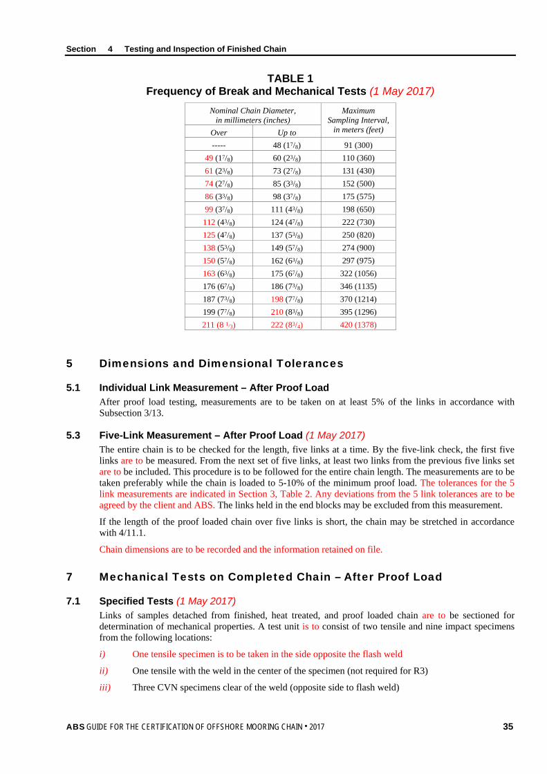
Section 4 Testing and Inspection of Finished Chain
TABLE 1 Frequency of Break and Mechanical Tests (1 May 2017)
Nominal Chain Diameter, in millimeters (inches)
Maximum Sampling Interval,
in meters (feet) Over Up to ----- 48 (17/8) 91 (300)
49 (17/8) 60 (23/8) 110 (360) 61 (23/8) 73 (27/8) 131 (430) 74 (27/8) 85 (33/8) 152 (500) 86 (33/8) 98 (37/8) 175 (575) 99 (37/8) 111 (43/8) 198 (650) 112 (43/8) 124 (47/8) 222 (730) 125 (47/8) 137 (53/8) 250 (820) 138 (53/8) 149 (57/8) 274 (900) 150 (57/8) 162 (63/8) 297 (975) 163 (63/8) 175 (67/8) 322 (1056) 176 (67/8) 186 (73/8) 346 (1135) 187 (73/8) 198 (77/8) 370 (1214) 199 (77/8) 210 (83/8) 395 (1296) 211 (8 1/3) 222 (83/4) 420 (1378)
5 Dimensions and Dimensional Tolerances
5.1 Individual Link Measurement – After Proof Load After proof load testing, measurements are to be taken on at least 5% of the links in accordance with Subsection 3/13.
5.3 Five-Link Measurement – After Proof Load (1 May 2017) The entire chain is to be checked for the length, five links at a time. By the five-link check, the first five links are to be measured. From the next set of five links, at least two links from the previous five links set are to be included. This procedure is to be followed for the entire chain length. The measurements are to be taken preferably while the chain is loaded to 5-10% of the minimum proof load. The tolerances for the 5 link measurements are indicated in Section 3, Table 2. Any deviations from the 5 link tolerances are to be agreed by the client and ABS. The links held in the end blocks may be excluded from this measurement.
If the length of the proof loaded chain over five links is short, the chain may be stretched in accordance with 4/11.1.
Chain dimensions are to be recorded and the information retained on file.
7 Mechanical Tests on Completed Chain – After Proof Load
7.1 Specified Tests (1 May 2017) Links of samples detached from finished, heat treated, and proof loaded chain are to be sectioned for determination of mechanical properties. A test unit is to consist of two tensile and nine impact specimens from the following locations:
i) One tensile specimen is to be taken in the side opposite the flash weld
ii) One tensile with the weld in the center of the specimen (not required for R3)
iii) Three CVN specimens clear of the weld (opposite side to flash weld)
ABS GUIDE FOR THE CERTIFICATION OF OFFSHORE MOORING CHAIN . 2017 35

Section 4 Testing and Inspection of Finished Chain
iv) Three CVN specimens with notch in weld seam
v) Three CVN specimens from the crown
Where the strain-aging properties of the steel have been documented by sufficient testing and comparative testing demonstrates that values obtained from heat treated, proof loaded chain are not significantly inferior to those from heat treated, non-proof loaded chain, the mechanical tests may be carried out on heat treated chain links that are not subjected to the proof load. Acceptance criteria for heat treated, non-proof loaded chain is to be agreed.
7.3 Test Frequency and Properties The test frequency is to be based on tests at sampling intervals according to Section 4, Table 1, provided that every cast is represented. Mechanical properties are to be as specified in Section 1, Table 1.
7.5 Frequency of Crown Impact Tests The frequency of impact testing in the bend may be reduced at the discretion of ABS, provided it is verified by statistical means that the required toughness is consistently achieved.
7.7 Hardness Tests (1 May 2017) Hardness tests are to be carried out on finished chain. The frequency and locations are to be agreed with ABS. The recorded values are for information only and used as an additional check to verify that the heat treatment process has been stable during the chain production.
9 Nondestructive Examination – After Proof Load Test (1 May 2017)
9.1 Visual Inspection After proof testing and cleaning, all surfaces of every link are to be visually examined by the manufacturer for workmanship, circularity, distortion, stud attachment, test grip damage, surface appearance, alignment of butt welds (eccentricity), and clamping die damage. Burrs, irregularities, and rough edges are to be contour ground. Links are to be uniform and have smooth internal radii, and are to be free from injurious surface imperfections such as mill defects, surface cracks, dents, and cuts, especially in the vicinity where gripped by clamping dies during flash welding. Studs are to be securely fastened.
The examination room/area should be appropriately illuminated and the chain should be positioned to have good access to all surfaces. In order to allow optimal access to the surface area it is recommended that chain be hung in the vertical position, however access to inspect the interlink area may only be possible with the chain in the horizontal position.
9.3 Nondestructive Examination – General Testing is to be performed in accordance with a recognized Standard and the procedures, together with acceptance/rejection criteria are to be submitted to ABS for approval. NDE personnel is to be qualified and certified according to ISO 9712, ACCP or equivalent. Personnel qualification to an employer or responsible agency based qualification scheme as SNT-TC-1A may be accepted if the employer’s written practice is reviewed and found acceptable and the Level III is ASNT Level III, ISO 9712 Level III, or ACCP Professional Level III and certified in the applicable method. NDE operators are to be qualified to at least Level II.
9.5 Magnetic Particle Inspection (MT) Magnetic particles are to be employed to examine the flash welded area, including the area gripped by the clamping dies. Procedures are to be submitted to ABS for approval. Procedures and equipment in accordance with those approved are to be used.
Frequency of examination is to be every link. Additionally, 10% of links are to be tested on all accessible surfaces. The examination room/area should be appropriately illuminated and the chain should be positioned to have good access to all surfaces. Link surfaces and the surface at the flash weld are to be free from cracks, lack of fusion and gross porosity. Testing is to be performed in accordance with ASTM E709 or another recognized standard (e.g. ISO 9934) using wet continuous fluorescent magnetization technique. Non-fluorescent techniques can be accepted in special cases where the standard inspection procedures are impractical.
36 ABS GUIDE FOR THE CERTIFICATION OF OFFSHORE MOORING CHAIN . 2017

Section 4 Testing and Inspection of Finished Chain
Links are to be free from:
• Relevant linear indications exceeding 1.6 mm in transverse direction
• Relevant linear indications exceeding 3.2 mm in longitudinal direction
• Relevant non-linear indications exceeding 4.8 mm.
Eddy Current (EC) testing can be considered subject to approval by ABS.
Stud welds, if used, are to be visually inspected. The toes of the fillets are to have a smooth transition to the link with no undercuts exceeding 1.0 mm. Additionally, at least 10% of the stud welds distributed through the length is to be dye penetrant tested according to ASTM E1417 or magnetic particle tested according to ASTM E1444 or equivalent. Cracks, lack of fusion or gross porosity are not acceptable. If defects are found, testing is to be extended to all stud welds in that length.
9.7 Ultrasonic Testing (UT) Ultrasonics are to be employed to examine the flash weld fusion. Procedures are to be submitted to ABS for approval. Procedures and equipment in accordance with those approved is to be used. On-site calibration standards for chain configurations are to be approved. Frequency of examination is to be every link.
The flash weld is to be free from defects causing ultrasonic back reflections equal to or greater than the approved calibration standard. The flash butt welds are to be ultrasonic tested (UT) in accordance with ASTM E587 or another recognized standard using single probe, angle-beam shear waves in the range from 45 to 70 degrees.
Single probe technique has limitations as far as testing of the central region is concerned and the flash weld imperfections such as flat spots may have poor reflectivity. Where it is deemed necessary, detectability of imperfections may need to be carried out by using a tandem technique, time of flight diffraction (TOFD) or phased array UT (PAUT).
PAUT and TOFD procedures are to be submitted for review. It is to be demonstrated to the satisfaction of ABS that processes are capable of satisfactorily detecting indications.
11 Retest, Rejection and Repair Criteria
11.1 Measurement of Five Links (1 May 2017) If the length of the proof loaded chain over five links is short, the chain may be stretched by loading above the proof test load specified in Section 3, Table 1, provided that:
i) The applied load is not greater than that and that qualified in Subsection 1/5
ii) Only random lengths of chain require stretching
iii) The permanent deformation on studless chain is no greater than 2.5%
If loading is required to stretch the chain, the final load and the chain length identification are to be noted on the inspection report. Special written approval is required in advance of chain manufacture where alterations to this procedure are required
If the length exceeds the specified tolerance, the over-length chain links are to be cut out and 4/11.3 is to apply.
11.3 Replacement of Defective Links (1 May 2017) If single links are found to be defective or to not meet other applicable requirements, defective links may be cut out and a connecting common link inserted in their place. The individual heat treatment and inspection procedure of connecting common links is subject to ABS approval. Other methods for repair are subject to the written approval by ABS and the end purchaser. Weld repair of chain is not permitted.
The use of connecting accessories (such as joining shackles, detachable connecting links, etc.) or connecting common links (splice links) to replace defective links is subject to the written approval of the end purchaser in terms of the number and type permitted. The use of connecting common links (splice links) is restricted to three links, on the average, in each 100 m (330 ft) of chain.
ABS GUIDE FOR THE CERTIFICATION OF OFFSHORE MOORING CHAIN . 2017 37

Section 4 Testing and Inspection of Finished Chain
11.5 Surface Defects If a crack, cut or defect in the flash weld zone, or any other region, is found by visual or magnetic particle examination, it is to be ground down no more than 5% of the link diameter in depth and streamlined to provide no sharp contours.
The theoretical cross sectional area of the link in way of the ground repair is not to be less than the theoretical cross section of the nominal chain diameter and the final dimensions are to still conform to the agreed standard.
Ground and blended links are to be subjected to magnetic particle or dye penetrant examination. Chain links are to be removed when they are found to contain defects exceeding 5% of the link diameter in depth.
11.7 Volumetric Defects If indications of interior of flash weld defects, in reference to the accepted calibration standards, are detected during ultrasonic examination, 4/11.3 is to apply.
11.9 Geometrical or Tolerance Failure If link diameter, length, width, and stud alignment do not conform to the required dimensions, these are to be compared to the dimensions of 40 more links; 20 on each side of the affected link. If a single particular dimension fails to meet the required dimensional tolerance in more than two (2) of the sample links, all links are to be examined. 4/11.3 is to apply.
11.11 Break Load Test Failure If a break load test fails, a thorough examination with the Surveyor informed in a timely manner is to be carried out to identify the cause of failure. Two additional break test specimens representing the same sampling length of chain are to be subjected to the break load test. Based upon satisfactory results of the additional tests and the results of the failure investigation, it will be decided what lengths of chain can be accepted. Failure of either or both additional tests will result in rejection of the sampling length of chain represented and 4/11.3 is to apply.
If indications are found in the flash butt weld zone that are not identified as cracks and have been found to be also present before the break test, a report is to be submitted explaining the reason for the indications together with an engineering assessment. If it is satisfactorily proven to ABS that the indications are not detrimental to the chain performance, then the requirement to carry out two additional break tests may be reconsidered.
11.13 Proof Load Test Failure (1 May 2017) If a link fails during proof load testing, a thorough examination/failure investigation, with the Surveyor informed in a timely manner, is to be carried out to identify the probable cause of failure of the proof test. In the event that two or more links in the proof loaded length fail, that section of proof loaded length is to be rejected. The above failure investigation is to be carried out with consideration to all factors or conditions thought to be causal to failure. Depending upon the results of the investigation, further consideration may need to be given to other lengths of chain produced.
11.13.1 Additional Break Load Tests In addition to the above failure investigation, a break test specimen is to be taken from each side of the one failed link, and subjected to the breaking test. Where multiple chains are produced simultaneously it is recognized that the preceding flash butt welded link and subsequent flash butt welded link will be on an alternative chain length or the other end of the chain length. In such cases ABS may require that two additional break tests are to be taken from the lengths of chain that include the preceding and subsequent welded links which may not necessarily be the adjacent links. Based upon satisfactory results of both break tests and the results of the failure investigation, it will be decided what length of chain can be considered for acceptance. Failure of either or both breaking tests will result in rejection of the same proof loaded length.
Replacement of defective links is to be in accordance with 4/11.3.
38 ABS GUIDE FOR THE CERTIFICATION OF OFFSHORE MOORING CHAIN . 2017

Section 4 Testing and Inspection of Finished Chain
If the investigation identifies defects in the flash butt weld or a lower strength flash weld “a glue-weld” is found, additional NDT such as PAUT is to be carried out to identify if other links are affected. A full assessment of the flash butt welding machine it to be carried out, together with assessment of the condition of the bar ends prior to welding.
11.15 Tensile Test Failure Retest requirements for tensile tests are to be in accordance with 2/3.5.4(a). Failure to meet the specified requirements of either or both additional tests will result in rejection of the sampling length of chain represented and 4/11.3 is to apply.
Alternatively, reheat treatment of the rejected length or the entire chain length may be considered.
11.17 Charpy Test Failure Retest requirements for Charpy impact tests are to be in accordance with 2/3.5.4(b). Failure to meet the requirements will result in rejection of the sampling length represented and 4/11.3 is to apply.
Alternatively, reheat treatment of the rejected length or the entire chain length may be considered.
13 Marking
13.1 Locations for Marking of Chain The chain is to be clearly marked on the following places:
i) For stud link – On the stud
ii) For studless – On the straight length on the side opposite the flash butt weld
iii) At each end of the chain length
iv) At intervals not exceeding 100 m (330 ft)
v) On each connecting common link (splice links)
vi) On each link next to shackles or connecting common links (splice links)
vii) At first and last common link of each steel heat
All marked links are to be stated on the certificate, and the marking is to make it possible to recognize leading and tail end of the chain. In addition to the above required marking, the first and last common link of each individual charge used in the continuous length are to be traceable and adequately marked.
The marking is to be permanent and legible throughout the expected lifetime of the chain.
13.3 Markings For stud link chain, the stud of each link identified above is to contain the following information. For studless chain, the outer straight length on the side opposite the flash butt weld of each link identified above is to contain the following information.
i) The number of the certificate (furnished by the Surveyor), e.g., 96 ST 1234
ii) The mark signifying that the chain has been satisfactorily tested to ABS requirements and the grade as applicable, i.e., AB/R3, AB/R3S, AB/R4, AB/R4S, or AB/R5
iii) The ABS Stamp
iv) The manufacturer name or trademark and the nominal chain diameter in millimeters or inches (when the chain manufacturer embosses the information in a permanent manner by some suitable means such as forging or casting, marking may be omitted)
v) Each connecting common link (splice link) is to have a unique identifying marking.
The Certificate number may be exchanged against an abbreviation or equivalent. If so, this is to be stated in the certificate.
ABS GUIDE FOR THE CERTIFICATION OF OFFSHORE MOORING CHAIN . 2017 39

Section 4 Testing and Inspection of Finished Chain
13.5 Chain Certificate Individual certificates are to be issued for each length of chain not containing an accessory. ABS’s certification of mooring chain to this Section applies only to the individual lengths of chain and does not include accessories, which are certified separately. The chain certificate is to contain information on the number and location of connecting common links (splice links).
The certificate number and replacement link number may be exchanged against an abbreviation or equivalent. If so, this is to be stated in the certificate.
15 Manufacturer’s Documentation (1 May 2017) A complete Chain Inspection and Testing Report in booklet form is to be provided by the chain manufacturer for each continuous chain length. This booklet is to include all dimensional checks, test and inspection reports, NDT reports, process records, photographs (e.g., for test failures and retests and for other subjects of documentary interest, such as break loaded samples) as well as any nonconformity, corrective action and repair work. All accompanying documents, appendices, and reports are to carry reference to the original certificate number.
Individual certificates are to be issued for each continuous single length of chain.
The manufacturer will be responsible for storing, in a safe and retrievable manner, all documentation produced for a period of at least 10 years.
40 ABS GUIDE FOR THE CERTIFICATION OF OFFSHORE MOORING CHAIN . 2017

S e c t i o n 5 : T e s t i n g a n d I n s p e c t i o n o f A c c e s s o r i e s
S E C T I O N 5 Testing and Inspection of Accessories
1 General (1 May 2017) This Section applies to but is not limited to mooring equipment accessories such as detachable connecting links (shackles), detachable connecting plates (triplates), end shackles, swivels and swivel shackles, and subsea connectors.
1.1 Accessory Manufacturing Process (1 May 2017) Offshore mooring chain accessories are to be manufactured in accordance with the approved manufacturing process. For accessory production a Manufacturing Procedure Specification (MPS) is to be submitted to ABS that details all critical aspects of accessory production, casting, forging, heat treating (including arrangement and spacing of components in the heat treatment furnaces), quenching, mechanical testing, proof and break loading and NDE.
1.3 Accessory Manufacturing Process Records Records of processing and heat treatment are to be made available for inspection by the Surveyor.
After final heat treatment, all accessories are to be subjected to proof load tests, sample break load tests, and sample mechanical tests in the presence of a Surveyor. Where the manufacturer has a procedure to record proof loads and the Surveyor is satisfied with the adequacy of the recording system, he need not witness all proof load tests. The Surveyor is to be satisfied that the testing machines are calibrated and maintained in a satisfactory condition. Prior to testing and inspection, the chain accessories are to be free from scale, paint, or other coating.
3 Proof and Break Load Tests Proof load and break load tests are to represent the installed configuration.
3.1 Proof Load Test All accessories are to be subjected to the proof load specified for the corresponding stud link chain, even if the accessories are intended for studless chain.
For test details and loads, refer to Section 3, Table 1.
Proof loading of accessories with large safety factors with regard to strength will be considered on a case-by-case basis.
3.3 Break Load Test (1 May 2017) Chain accessories are to be tested at the break load prescribed for the grade and size of chain for which they are intended. Each specimen is to be capable of withstanding the break load specified without fracture. It is to be considered acceptable if the specimen is loaded to the specified value and maintained at that load for 30 seconds without cracking.
At least one accessory out of every batch or every 25 accessories, whichever is less, is to be tested.
For individually produced accessories or accessories produced in small batches (less than five), and accessories that have a safety factor over two times the break load of the intended chain, alternative testing will be subject to special consideration. Alternative testing is to be approved by ABS and the following additional conditions may apply:
ABS GUIDE FOR THE CERTIFICATION OF OFFSHORE MOORING CHAIN . 2017 41
Section 5 Testing and Inspection of Accessories
i) Alternative testing is described in a written procedure and manufacturing procedure specification (MPS).
ii) A finite element analysis is provided at the break load and demonstrates that the accessory has a safety margin over and above the break load of the chain.
iii) Strain age testing (as per approved procedure by ABS) is carried out on the material grade produced to the same parameters at the time of qualification.
iv) If an accessory is of a large size that will make heat treating in batches unfeasible or has a unique design, strain gauges are to be applied during the proof and break load tests during initial qualification and during production. The strain gauge results from production are to be comparable with the results from qualification.
For test details and loads, refer to Section 3, Table 1.
3.5 Definition of a Batch A batch is defined as accessories that originate from the same heat treatment charge and the same heat of steel. Also refer to Subsections 2/5 and 2/7.
3.7 Accessories Subjected to Break Test The accessories which have been subjected to the break load test are to be destroyed and not used as part of an outfit, with the exceptions given in 5/3.9.
3.9 Over-Designed Accessories (1 May 2017) Where the accessories are of increased dimension or alternatively a material with higher strength characteristics is used, they may be included in the outfit at the discretion of ABS, provided that:
i) The accessories are successfully tested at the prescribed breaking load appropriate to the chain for which they are intended, and
ii) It is verified by procedure tests that such accessories are so designed that the breaking strength is not less than 1.4 times the prescribed breaking load of the chain for which they are intended.
iii) Strain age properties have been carried out on the material grade produced to the same parameters.
iv) Strain gauges are to be applied during the break load test in the high stress locations to monitor that the strains stay within allowable limits.
5 Dimensions and Dimensional Tolerances 100% of accessories are to be checked for dimensions after proof load testing. The manufacturer is to provide a statement indicating compliance with the purchaser’s requirements.
5.1 Dimensional Tolerances (1 May 2017) The following tolerances are applicable to accessories:
i) Nominal diameter: +5%, –0%
ii) Other dimensions: ±2.5%
iii) Negative tolerance of –2.5% in the plane of a shackle at the crown can be permitted provided the cross-sectional area of the shackle at that point is at least the theoretical area of the nominal diameter. The cross sectional area at the crown is to be calculated using the average of the diameters with negative tolerance and plus tolerance, measurements are to be taken from at least 2 locations approximately 90 degrees apart.
These tolerances do not apply to machined surfaces, which will be indicated on the approved drawing.
42 ABS GUIDE FOR THE CERTIFICATION OF OFFSHORE MOORING CHAIN . 2017

Section 5 Testing and Inspection of Accessories
7 Mechanical Tests (1 May 2017) Accessories are to be subjected to mechanical testing as described in Subsections 2/1 (Rolled Plate), 2/3 (Rolled Bar), 2/5 (Forged Steel), and 2/7 (Cast Steel). Mechanical tests are to be taken from proof loaded full size accessories that have been heat treated with the production accessories they represent. At least one accessory out of every batch or every 25 accessories, whichever is less, is to be tested. Hardness tests are to be carried out on finished accessories. The frequency and locations are to be agreed with ABS. The recorded values are for information only and used as an additional check to verify that the heat treatment process has been stable during the accessory production.
The use of separate representative coupons is not permitted except as indicated in 5/7.7 below.
Where the strain-aging properties of the steel have been documented by sufficient testing and comparative testing demonstrates that values obtained from heat treated, proof loaded accessories are not significantly inferior to those from heat treated, non-proof loaded accessories, the mechanical tests may be carried out on heat treated accessories that are not subjected to the proof load. Acceptance criteria for heat treated, non-proof loaded accessories is to be agreed.
7.1 Test Location of Forged Shackles Forged shackle bodies and forged Kenter shackles are to have a set of three impact tests and a tensile test taken from the crown of the shackle. Tensile tests on smaller diameter shackles can be taken from the straight part of the shackle, where the geometry does not permit a tensile specimen from the crown. The tensile properties and impact values are to meet the requirements of Section 1, Table 1 in the locations specified in Section 2, Figure 1, with the Charpy pieces on the outside radius of the crown.
7.3 Test Location of Cast Shackles The locations of mechanical tests of cast shackles and cast Kenter shackles can be taken from the straight part of the accessory. The tensile properties and impact values are to meet the requirements of Section 1, Table 1 in the locations specified in Section 2, Figure 1.
7.5 Complex Geometry Accessories (1 May 2017) The locations of mechanical tests of other accessories with complex geometries are to be agreed with ABS.
For non-circular sections, 1/4t (thickness) from the surface is considered appropriate.
Rolled plates are to be tested to the Standard to which they are produced.
Material properties in high stressed locations in the load path are to be represented, and in addition, consideration is to be given to representing the properties where they are expected to be worst. The tensile properties and impact values are to meet the requirements of Section 1, Table 1 in the locations specified in Section 2, Figure 1.
7.7 Individual Accessories or Small Batches (1 May 2017) For individually produced (heat treated) accessories or accessories produced in small batches, (less than five), alternative testing can be proposed to ABS.
Each proposal for alternative testing is to be detailed by the manufacturer in a written procedure and submitted to ABS, and the following additional conditions may apply:
i) If separately forged or cast coupons are used, they are to have a cross-section and, for forged coupon, a reduction ratio similar to that of the accessories represented, and are to be heat treated in the same furnace and quenched in the same tank at the same time, as the actual forgings or castings. Thermocouples are to be attached to the coupon and to the accessories.
ii) If separately forged or cast coupons are agreed, it is to be verified by procedure test that coupon properties are representative of accessory properties.
It is to be established that alternative testing represents the actual accessory material properties in high stressed locations in the load path, and in addition, consideration is to be given to representing the properties where they are expected to be worst.
ABS GUIDE FOR THE CERTIFICATION OF OFFSHORE MOORING CHAIN . 2017 43

Section 5 Testing and Inspection of Accessories
ABS’s decision to accept representative testing will also take into consideration the intended application and design life of the project for which the accessories are intended.
7.9 Definition of a Batch A batch is defined as accessories that originate from the same heat treatment charge and the same heat of steel. Also refer to Subsections 2/5 and 2/7.
7.11 Test Location of Pins Mechanical tests of pins are to be taken as per Section 2, Figure 1 from the mid length of a sacrificial pin of the same diameter as the final pin. For oval pins, the diameter taken is to represent the smaller dimension.
Mechanical tests may be taken from an extended pin of the same diameter as the final pin that incorporates a test prolongation and a heat treatment buffer prolongation, where equivalence with mid length test values have been established. The length of the buffer is to be at least equal to one pin diameter dimension which is removed after the heat treatment cycle is finished. The test coupon can then be removed from the pin. The buffer and test are to come from the same end of the pin as per Section 5, Figure 1. Also refer to 2/3.13 for heat treatment of rolled bars for pins and 2/5.5 for heat treatment of forged pins.
FIGURE 1 Pin Heat Treatment Buffer
PIN TEST BUFFER
9 Nondestructive Examination – After Proof Load Test (1 May 2017)
9.1 Visual and Surface Examination After proof load testing and cleaning, all surfaces of every accessory are to be subjected to a close visual examination by the manufacturer for workmanship, circularity, and surface appearance. Special attention is to be paid to machined surfaces and high stress regions. All non-machined surfaces are to be sand or shot blasted to a surface finish of minimum Sa 2.5 to permit a thorough examination. Where applicable, accessories are to be dismantled for inspection of internal surfaces. Burrs, irregularities, and rough edges are to be contour ground. Accessories are to be uniform and have smooth internal radii, and are to be free from injurious surface imperfections, such as surface cracks, dents, and cuts. The examination room/area should be appropriately illuminated and the chain should be positioned to have good access to all surfaces.
On accessories only, grinding and blending repair may go beyond 5% of the accessory diameter provided the stress concentration factors do not exceed that of the common link and that the theoretical cross sectional area (CSA) of the accessory is maintained.
9.3 Nondestructive Examination – General Testing is to be performed in accordance with a recognized Standard, such as those indicated below, or equivalent. The procedures, together with acceptance/rejection criteria are to be submitted to ABS for review.
NDE personnel are to be qualified and certified according to ISO 9712, ACCP or equivalent. Personnel qualification to an employer or responsible agency based qualification scheme as SNT-TC-1A may be accepted if the employer's written practice is reviewed and found acceptable and the Level 3 is ASNT Level III, ISO9712 Level III or ACCP Professional Level III and certified in the applicable method. NDE operators are to be qualified to at least Level II.
44 ABS GUIDE FOR THE CERTIFICATION OF OFFSHORE MOORING CHAIN . 2017
Section 5 Testing and Inspection of Accessories
9.3.1 Surface NDE All chain accessories are to be checked by magnetic particles or dye penetrant. Testing is to be performed in accordance with standards referenced using the fluorescent technique. As a minimum surfaces are to be free from:
• Relevant linear indications exceeding 1.6 mm in transverse direction
• Relevant linear indications exceeding 3.2 mm in longitudinal direction
• Relevant non-linear indications exceeding 4.8 mm.
Procedures and equipment in accordance with those approved are to be used. The areas to be subjected to surface NDE are to include high stress areas, machined surfaces, areas of abrupt geometrical changes, and areas where defects are most likely. If MT is used, accessories should be magnetized, if possible, in two mutually perpendicular directions. The examination room/area should be appropriately illuminated and the accessories should be positioned to have good access to all surfaces.
Recognized standards for magnetic particle testing (MT) of forgings: EN 10228-1, ASTM A275, Using wet continuous magnetization technique or equivalent standards such as ISO 4986, IACS Rec 69
Recognized standards for magnetic particle testing (MT) of castings: ASTM E709, Using wet continuous magnetization technique
Eddy Current (EC) testing can be considered subject to approval by ABS.
9.3.2 Ultrasonic Examination All chain accessories, both forgings and castings, are to be subjected to ultrasonic examination to the standard submitted and approved in connection with the qualification of the manufacturer. On-site calibration standards for chain configurations are to be approved. Frequency of examination is to be every accessory. The accessory is to be free from defects causing ultrasonic back reflections equal to or greater than the approved calibration standard.
Recognized standards for ultrasonic testing (UT) of forgings: EN 10228-3, ASTM A388, ISO 13588
Recognized standards for ultrasonic testing (UT) of castings: ASTM A609, ISO 13588
9.3.3 Repairs Weld repairs of finished accessories are not permitted.
9.5 Manufacturer’s Statement The manufacturer is to provide a statement that nondestructive examination has been carried out with satisfactory results. This statement is to include a reference to the techniques and to the operator’s qualification.
11 Test Failures In the event of a failure of the break or proof load test, the entire batch represented by the test is to be rejected unless the cause of failure has been determined and it can be demonstrated to the Surveyor’s satisfaction that the condition causing the failure is not present in any of the remaining accessories.
In the event of mechanical test failure, tension and impact retests as permitted in 2/3.5.4 (bar), 2/5.9.3 (forgings), and 2/7.9.2 (castings) can be carried out. Failure of any mechanical retest will result in rejection of the entire lot.
Alternatively, reheat treatment of the rejected lot may be considered.
ABS GUIDE FOR THE CERTIFICATION OF OFFSHORE MOORING CHAIN . 2017 45

Section 5 Testing and Inspection of Accessories
13 Marking and Certification
13.1 Marking (1 May 2017) Each accessory is to be marked as follows:
i) Chain grade The mark signifying that the accessory has been satisfactorily tested to ABS requirements and the grade as applicable (i.e., AB/R3, AB/R3S, AB/R4, AB/R4S, or AB/R5)
ii) The number of the certificate (furnished by the Surveyor), e.g., 96 ST 1234
iii) The manufacturer name or trademark and the nominal accessory diameter in millimeters or inches (when the accessory manufacturer embosses the information in a permanent manner by some suitable means such as forging or casting, marking may be omitted)
iv) Each accessory is to have a traceable identifying marking
v) Each detachable component part is to be stamped or marked with an identifying number to avoid mixing components.
vi) The marking is to be permanent and legible throughout the expected lifetime of the accessory.
13.3 Certificates Individual certificates are to be issued for each type of accessory. The accessory identification numbers are to be included on the certificate.
The Certificate number may be exchanged against an abbreviation or equivalent. If so, this is to be stated in the certificate.
15 Documentation (1 May 2017) A complete Inspection and Testing Report in booklet form is to be provided by the manufacturer for each order. This booklet is to include all dimensional checks, test and inspection reports, NDT reports, process records, and example photographs of components positioned in furnaces, as well as any nonconformity, corrective action, and repair work.
Each type of accessory is to be covered by separate certificates.
All accompanying documents, appendices, and reports are to carry reference to the original certificate number.
The manufacturer will be responsible for storing, in a safe and retrievable manner, all documentation produced for a period of at least 10 years.
46 ABS GUIDE FOR THE CERTIFICATION OF OFFSHORE MOORING CHAIN . 2017

A p p e n d i x 1 : C h a f i n g C h a i n f o r S i n g l e P o i n t M o o r i n g A r r a n g e m e n t s
A P P E N D I X 1 Chafing Chain for Single Point Mooring Arrangements (1 May 2017)
1 Scope These requirements apply to short lengths (approximately 8m) of 76mm diameter chain to be connected to hawsers for the tethering of oil carriers to single point moorings, FPSO’s and similar uses.
3 Approval of Manufacturing The chafing chain is to be manufactured by works approved by ABS according to Subsections 1/5 and 1/11.
5 Materials The materials used for the manufacture of the chafing chain are to satisfy the requirements of this Guide.
7 Design, Manufacturing, Testing and Certification i) The chafing chain is to be designed, manufactured, tested and certified in accordance with this
Guide except that batch heat treatment is permitted.
ii) The arrangement of the end connections is to be of an approved type.
iii) The common link is to be of the stud link type – Grade R3 or R4.
iv) The chafing chain is to be capable of withstanding the breaking test loads of 4884kN (Grade R3) and 6001 kN (Grade R4). See Note 1.
v) The chain lengths are to be proof load tested in accordance with this Guide. The test load for Grade R3 is 3242k N and for Grade R4 is 4731 kN.
Notes: 1 Documented evidence of satisfactory testing of similar diameter mooring chain in the prior 6-month
period may be used in lieu of break testing subject to agreement with ABS.
2 The requirements herein are also applicable to other diameter chafing chains, such as 84 mm and 96 mm, subject to compliance with the proof and break load requirements specified for the chain grade and diameters in Section 3, Table 1.
ABS GUIDE FOR THE CERTIFICATION OF OFFSHORE MOORING CHAIN . 2017 47