Offering a step-change in seismic technology
12
Offering a step-change in seismic technology www.tectonus.com 1016 RSFJ - Product Catalogue
Transcript of Offering a step-change in seismic technology

Offering a step-change in seismic technology
www.tectonus.com 1016
RSFJ - Product Catalogue

2

3
Resilient seismic solutions
Resilient Slip Friction Joint (RSFJ)
With a clear global issue of rising impact of earthquakes and aftershocks, there is an ever-growing demand to minimise fatality risk and economic impact of seismic events.
Damage in recent major earthquakes has resulted in efforts by engineers to develop techniques which not only provide life-safety, but also aim to minimise damage so that buildings could be reoccupied quickly with minimal business interruption and repair costs.
There are two key characteristics that need to be provided for a structure to be able to resist the earthquake loads with minimum damage:
• damping• self-centering
With the capabilities and advantages of the Resilient Slip Friction Joint those key characteristics are met, raising the resilience of the structure.
Tectonus
Tectonus is a structural solutions company offering earthquake-proofing technology with the innovative Resilient Slip Friction Joint.
The patented RSFJ technology allows buildings to withstand seismic activity by providing friction damping and self-centring function; two combined characteristics which greatly improve building resilience and minimize the damage after severe earthquake events and aftershocks.
This cutting-edge technology is scalable with a compact design allowing it to be implemented in new and retrofit projects of steel, timber or concrete materials for low to high rise structures. Patented technology
The RSFJ technology is a unique and innovative solution for raising seismic resilience in structures. With the capacity to dissipate earthquake energy as well as self-centre after the event and any following aftershocks, this compact joint is exceptionally scalable and can be used in all types of new and retrofitted structures of various materials (timber, steel and concrete).
The key patented elements of the RSFJ technology includes the unique shape of the plate grooves, high strength bolts with disc springs which are responsible for the desirable self-centering and damping capabilities.
Contents
RSFJ advantages
RSFJ operation
Smart RSFJ
Applications
Joint design considerations
Hysteresis loops
Case studies
Product table
Contact us
4
5
5
6
7
8
9
10
12

4
RSFJ advantagesConventional seismic solutions were established on “high-damage” concepts; dissipating seismic energy with the entire structure ultimately experiencing significant level of damage.
Advancements in seismic solutions in the last decades resulted in “low-damage” concepts where the damage is controlled and limited to sacrificial fuses or joints in the structure, replaceable after events (usually at a high cost).
The innovative RSFJ technology offers a third generation solution providing “damage-avoidance” due to its maintenance free design. It is a cost efficient and market changing technology with limitless potential and benefits.
Effective dissipation of energy Significantly reducing the seismic load through friction damping and thus improving structural resilience.
Self-centring capacityRestoring the structure to its initial position after each seismic event.
Damage avoidanceFollowing a seismic event, the RSFJ is ready for any aftershocks that may occur and will perform this way throughout lifetime of the structure.
High initial stiffness Resisting to wind loads and limiting the drift of structures under serviceability seismic loads.
Maintenance freeNo elements of the RSFJ requires service or periodic / post event maintenance.
Cost-effectiveMaintenance free with life-long durability, the RSFJ avoids the expensive post-event re-tensioning / replacement costs.
Applicable to all building materialsCan be implemented in any structural project. It can be part of any Lateral Load Resisting System (LLRS) and connected to timber, steel and concrete structural members.
For new and retrofit structuresBecause of its ease of connection to existing structural members, the RSFJ can be part of any building retrofit project.
Scalable The connector is fully scalable and is custom designed to a variety of structural requirements with uses ranging from storage units to high rise structures.
Compact sizeConfiguration of the RSFJ is smaller than many comparable seismic connectors.
Simple installationThe RSFJ installation is similar to the installation of bolted steel plate connections. The disc springs are to be installed in accordance with the design intent and their initial design prestress force can be easily reached using a simple deformation gauge.
Structural health monitoringWhen used with a displacement sensor, the Smart RSFJ can be used to monitor the structural integrity of a building structure. Measurements of displacement in the order of 15-40 mm allow for high precision of the actual forces being applied to structural elements, resulting in better assessment of the condition of the structure following an earthquake.

5
RSFJ operation
Smart RSFJ
The displacement of the RSFJ can be directly related to the force applied to it with high precision. Therefore, it can be instrumented with sensors for structural health monitoring.
The joint displacement of RSFJ can be directly related to the force applied to it with high precision and therefore can be instrumented by sensors for structural health monitoring.
Sensors would determine the deflection of the joint and the structure, the exact forces to which the joint and the structure have been subjected and eventually any potential stiffness degradation of the whole structure as a result of structural damage.
• Sensors integrated into the RSFJ may be self-powered.
• Information sensed at the sensors may betransmitted by wireless means to a datacollection system.
• Data from a single joint may be combined withdata from other joints to provide aggregateinformation about portions or the entirety ofstructures.
The outer cap plates and the centre slotted plates are grooved and clamped together with high strength bolts and disc springs. When the joint force overcomes the frictional resistance between the sloped surfaces, the centre slotted plates start to slide and energy will be dissipated through cycles of sliding.
The specific shape of the plates ridges along with the use of washers and high strength bolts provide the desirable self-centring characteristic.
The angle of the grooves is designed in such a way that at the time of unloading, the reversing force induced by the elastically compacted washers is larger than the resisting friction force acting between the plates surfaces. Therefore, the system is re-centered by the reversing force upon unloading.
Moreover, the lateral resistance of this new joint is higher than conventional flat plates friction joints for a similar clamping force provided by high strength bolts.
It should be noted that the sliding plates will only travel the length of one groove as their movements are restricted by the completely flattened (or locked) disc springs. The length of the groove to accommodate the bolts in the middle plates and the number of washers will be designed to achieve the displacement required for a targeted ductility.
Cap and slotted plates
Disk springs High strength bolts
6
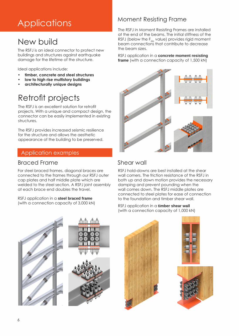
Applications
New build
Retrofit projectsThe RSFJ is an excellent solution for retrofit projects. With a unique and compact design, the connector can be easily implemented in existing structures.
The RSFJ provides increased seismic resilience for the structure and allows the aesthetic appearance of the building to be preserved.
The RSFJ is an ideal connector to protect new buildings and structures against earthquake damage for the lifetime of the structure.
Ideal applications include:• timber, concrete and steel structures• low to high rise multistory buildings• architecturally unique designs
RSFJ application in a steel braced frame (with a connection capacity of 3,000 kN)
Braced FrameFor steel braced frames, diagonal braces are connected to the frames through our RSFJ outer cap plates and half middle plate which are welded to the steel section. A RSFJ joint assembly at each brace end doubles the travel.
Application examples
RSFJ application in a timber shear wall (with a connection capacity of 1,000 kN)
RSFJ application in a concrete moment resisting frame (with a connection capacity of 1,500 kN)
Moment Resisting Frame
Shear wallRSFJ hold-downs are best installed at the shear wall corners. The friction resistance of the RSFJ in both up and down motion provides the necessary damping and prevent pounding when the wall comes down. The RSFJ middle plates are connected to steel plates for ease of connection to the foundation and timber shear wall.
The RSFJ in Moment Resisting Frames are installed at the end of the beams. The initial stiffness of the RSFJ (below the Fslip value) provides rigid moment beam connections that contribute to decrease the beam sizes.

7
Joint design considerations Design procedures have been developed for different possible configurations of RSFJ: symmetric, asymmetric, and combined symmetric-asymmetric.
The flag-shaped hysteresis loop shows the cyclic performance of the joint which can be identified by the slip force (Fslip), ultimate resistance (Fult), restoring capacity (Frestoring), residual resistance (Fresidual), and the joint ultimate displacement (δult).
Fully self-centring flag-shaped hysteresis response
At rest before slip
At ultimate unloading
At ultimate loading
At restored position
The RSFJ is easily integrated in the structural analysis and design software SAP2000. It allows the designer to accurately calibrate the parameters according to the requirements of the project.
The RSFJ load displacement behaviour in SAP2000 can be easily modeled by choosing the Damper-Friction spring type element.
This function accurately represents the cyclic behaviour of a RSFJ providing its parameters are properly calibrated in accordance with the design parameters of the joint, which are:
• slip force• loading stiffness• maximum loading force• maximum uploading force• residual force
Structural analysis using SAP2000
Linear AnalysisWhen the applied load is greater than the slip force, the sliding in the joint occurs, resulting in rocking of the structure. Therefore, the Fslip has to be higher than the serviceability loads such as wind forces. By conducting numerical analysis, the optimum sliding force can be specified, ranging between 50% to 75% of the joint ultimate capacity. The magnitude of the restoring force is also a critical factor to be taken into account for a resilient seismic design to provide re-centring of the structure.

8
RSFJ capacity hysteresis loops
RSFJ limitless possibilities
1. Groove Angle 2. Coefficient of friction
3. Number of bolts 4. Number of washers (in parallel)
5. Number of washers (in series) 6. Pre-stressing force
The cyclic hysteresis responses illustrate the effect of connection parameters on its performance comprising the variations in magnitude of the slip force, ultimate capacity, restoring force, residual resistance, joint displacement and hysteresis damping ratio (ξhyst).
The connection parameters studied consist of the angle of the groove, coefficient of friction (CoF), number of disc springs in series and parallel, number of bolts, and the initial pre-stressing force of the bolts.
The difference between the Fult and Frestoring indicates the frictional resistance that needs to be overcome during unloading to allow the joint to reverse back to its original position.
As shown in Figures 1 and 6, by adopting a higher CoF (through different material arrangements for the sliding surfaces) and increasing the clamping force (through using more bolts), the frictional resistance increases accordingly, as theoretically expected.
By comparing the connection parameters effect on the hysteresis damping ratio, it can be found that only the increase of the groove angle has a reverse effect on the ξhyst. Increasing the CoF, number of washers in parallel, and also the pre-stressing force result in a larger ξhyst while increasing the number of washers in series and number of bolts have no effect.
(θi < θi+1 ; ξhyst,i < ξhyst,i+1) (CoFi < CoFi+1 ; ξhyst,i < ξhyst,i+1)
(Nw,i < Nw,i+1 ; ξhyst,i > ξhyst,i+1)
(Fpr,i < Fpr,i+1 ; ξhyst,i < ξhyst,i+1)(Nw,i < Nw,i+1 ; ξhyst,i = ξhyst,i+1)
(Nb,i < Nb,i+1 ; ξhyst,i = ξhyst,i+1)

9
Testing RSFJ on CLT wallRSFJ hysteretic behaviour testing
Case studies
Two identical RSFJ specimens were tested, configuration of the joint are shown in the image below.
The RSFJ hold-downs were implemented in the notches at the bottom corner of the CLT wall. They consisted of two centre slotted plates and two cap plates. The cap plates were manufactured using mild steel grade 350 and the centre plates were fabricated with high-strength Bisplate 80 steel. The angle of the grooves was 15 degrees in order to maximize the deformation capacity of the joint. Two 220 mm by 50 mm mild steel stiffener plates had later been welded to the cap plates to reinforce them against out of plane bending.
A double acting symmetric RSFJ was fabricated and tested with a 100 kN Instrom device.
Cap plates were manufactured with mild steel grade 300 and slotted centre plates with bisalloy grade 400. Four high strength bolts with minimum of 830 MPa tensile strength were employed (two bolts in each side).
The stack of disc springs on each side of each bolt comprised of four series springs with 38 kN of ultimate load at flat position. The pre-stressed force of each bolt (Fb,pr) was 5 kN. The stacks of disc springs were placed under the nuts of the bolts and the bolts were tightened until the desired pre-stressed force (5 kN) per bolt was achieved.
A specific lubricant was used between the cap plates and centre plates to increase the durability of the friction surfaces by controlling the possible galling and rusting.
The RSFJ were designed and built to be able to accommodate a maximum displacement of 65 mm in tension and 15 mm in compression. This was because of the relatively larger displacement demand in tension in comparison to the one in compression in a hold-down connector. These displacement thresholds were determined based on the analytical prediction of the RSFJ behaviour.
Cap and centre slotted plates
Test specimen
Schematic test setup
RSFJ deformation in compression RSFJ deformation in tension
Assembled RSFJDisc springs

10
RSFJ product tables The capacity and deflection of RSFJ products are shown in the following tables. The tables are categorised based on the groove angle and the connection overall deflection range. One can refer to the appropriate table by knowing the required deflection and then adopting a product with the targeted capacity.
Each product generates a specific hysteresis curve which can be easily identified by the values provided in the tables. This flag-shaped behaviour can then be incorporated into SAP2000 for structural modeling and analysis under cyclic loading, as described in previous section.
Note that the RSFJ scalability allows for an extended range well below and above the standard category and can be easily designed to your specifications. Our engineering consultants can assist in assessing your requirements for each project.
Category 30 (Groove angle of 30° - Deflection up to 20 mm)
For Category 30, • Fresidual = 0.46*Fslip
Category 25 (Groove angle of 25° - Deflection ranging from 20 to 40 mm)
For Category 25, • Fresidual = 0.41*Fslip
Category 20 (Groove angle of 20° - Deflection ranging from 40 to 60 mm)
For Category 20, • Fresidual = 0.34*Fslip
* On the illustrated hysteresis curves, Fslip could be set by the designer (typically as 50% of Fult).

Notes

0800 866 871
General queriesemail: [email protected]
Sales queriesemail: [email protected]
Design & specification queriesemail: [email protected]
www.tectonus.com