Evaluation of Some Proposed Methods for Protecting Bridge ...

PLANSOF PROPOSED
LOCATION
ROADWAY WIDTH
SUBSTRUCTURE
SUPERSTRUCTURE
LENGTH SHEET LEGEND
MAP HERE
PLACE LOCATION
P.P.C.C. BRIDGE OVERON
R.M. OF
IN
9 600 OUT TO OUT OF GIRDERS
WITH STEEL H-PILES
TWO PRECAST CONCRETE ABUTMENTS AND ONE INTERMEDIATE BENT
CHANNEL GIRDERS WITH ASPHALT OVERLAY
TWO SIMPLY SUPPORTED SPANS OF PRECAST PRESTRESSED CONCRETE
24 368 OUT TO OUT OF ABUTMENT PRECAST BACKWALL PANELS
PRECAST PRESTRESSED CHANNEL GIRDER DETAILSG5.
PRECAST PRESTRESSED CHANNEL GIRDER DETAILSG4.
PRECAST PRESTRESSED CHANNEL GIRDER DETAILSG3.
PRECAST PRESTRESSED CHANNEL GIRDER DETAILSG2.
PRECAST PRESTRESSED CHANNEL GIRDER DETAILSG1.
PRECAST PANEL DETAILSP2.
PRECAST PANEL DETAILSP1.
RAILPOST DETAILS14.
RAILING DETAILS13.
RAILING LAYOUT AND DETAILS12.
BEARING AND ERECTION DETAILS11.
STEEL PILE CAP DETAILS10.
STEEL PILE CAP DETAILS9.
ASSEMBLY DETAILS8.
ASSEMBLY DETAILS7.
ASSEMBLY DETAILS6.
EROSION CONTROL DETAILS5.
SITE AND EROSION CONTROL DETAILS4.
BORING LOGS3.
GENERAL ELEVATION2.
COVER SHEET1.
Not to Scale
AND STATIONS ARE IN METRES (m) UNLESS SHOWN OTHERWISE.
ALL DIMENSIONS ARE IN MILLIMETRES (mm) AND ALL ELEVATIONS
DATE:
DATE:
______
_____
CHECKED BY:
DRAWN BY:
SITE No.
SHEET No. 1
N
RELEASED FOR CONSTRUCTION BY :
LOCATION MAP
CONSTRUCTION
ISSUED FOR
WATER MANAGEMENT AND STRUCTURES
ENVIRONMENTAL APPROVALS
MANITOBA ENVIRONMENT ACT LICENCE
FISHERIES AND OCEANS CANADA - AUTHORIZATION OR REVIEW
TRANSPORT CANADA - NAVIGATION ACT
ENVIRONMENTAL REVIEW COMPLETED
DATE
EXECUTIVE DIRECTOR OF STRUCTURES
MANITOBA INFRASTRUCTURE
FILE # :
DATE :
FILE # :
DATE :
FILE # :
DATE :
FILE # :
DATE :
COMPLETED BY :
DATE :
MANITOBA INFRASTRUCTURE ENVIRONMENTAL APPROVAL
TP. -
RGE. -
DESIGN DATA
HYDRAULIC DESIGN DATA
DESIGN DISCHARGE
V3% = m/s
Q3% = Ë/sec
kNkNFACTORED BEARING RESISTANCE
kNkNMAXIMUM FACTORED LOAD
END PILE BENTS INTERMEDIATE PILE BENTS
20-13 ! low relaxation strands, fpu = 1 860 MPa
HSS Tubing for Bridge Rail shall confrom to CAN/CSA- G40.21-M92 Grade 350W2.
All Structural Steel shall conform to CAN/CSA G40.21-M92 Grade 300W1.
PRECAST PANELS - CAN/CSA-G30.18-M92 Grade 400W black (i.e no epoxy coating)2.
PRECAST PRESTRESSED CONCRETE CHANNEL GIRDERS - CAN/CSA-G30.18-M92 Grade 400W black (i.e no epoxy coating)1.
PRECAST PANELS - f'c = 35 MPa2.
f'ci = 35 MPa at 28 days
f'c = 45 MPa at time of destressingPRECAST PRESTRESSED CONCRETE CHANNEL GIRDERS -1.
CSA A23.1, Exposure Class C-1 Air content category 1
AASHTO LRFD "HL-93" Loading2.
Modified AASHTO HSS-25 Truck1.
AASHTO LRFD Bridge Design Specifications, First Edition, 1994 plus 1996/97 Interims
PILE LOADING
PRESTRESSING STRAND
STRUCTURAL STEEL
REINFORCING STEEL
STRUCTURAL CONCRETE
VEHICULAR LIVE LOADING
SPECIFICATIONS

Piles
of
|
Piles
of
|
Roadway
of
|
1 : 75
or as shown
2
GENERAL ELEVATION
Asphalt overlay
SU.1 SU.2
Scale 1:50
SU.3
Piles
of
|
Batter
1 : 8
6 500
6 500
2% or m
ore 2% or m
ore
Ste
el
H-Piles 310 x 110
2% or more
1%1%
1%1%
concrete channel girders650 deep precast prestressed
ELEVATION
PLAN
CROSS SECTION
Batter
1 : 8
700
700
Bridge
of
|
Final pavement Elev. 482.580 m
11 88011 880
2 500 1 560 2 5001 560
2 500 1 560 2 5001 560
4 800 4 800
8 girders @ 1 200 = 9 600
9 600
134
38
680
2 Spaces
@ 2 10
0 = 4 200
1 050
1 050
2 Spaces
@ 2 10
0 = 4 200
680
680
2 Spaces
@ 2 10
0 = 4 200
1 050
1 050
2 Spaces
@ 2 10
0 = 4 200
680
3 Spaces
@ 1 400 = 4 200
250 x 85
Steel H-Piles
250 x 85
Steel H-Piles
24 368 out to out of precast backwall panels
Ste
el
H-Piles 310 x 110
Ste
el
H-Piles 310 x 110
250 x 85
Steel H-Piles
250 x 85
Steel H-Piles
FL
OW
900
3 Spaces
@ 1 400 = 4 200
of ste
el c
ap channel
Dim
ensio
ns alo
ng |
2%2%
2% or m
ore
2% or m
ore
See Sheet 04 - Site and Erosion Control Details
Rip rap not shown for clarity
located on Sheet 4 (typ.)
see "ABUTMENT DRAINAGE END TREATMENT"
CSP to meet side slopes
HERE
ELECTRONIC SEAL
PLACE ENGINEERS
NORTH or WEST SOUTH or EAST
m long
HP 250 x 85,
Steel piles
m long
HP 310 x 110,
Steel piles
m long
HP 310 x 110,
Steel piles
m long
HP 310 x 110,
Steel piles
m long
HP 250 x 85,
Steel piles
Elev. m
Pile cut-off
Elev. m
Pile cut-off
Elev. m
Pile cut-off
@ | of roadway
Elev. m
Final pavement@ | of roadway
Elev. m
Final proposed pavement
@ | of roadway
Elev. m
Final proposed pavement
Elev. m
| of roadway
Proposed groundline along
Sta.
Bridge
of
|
P.R.
No.
Road
way
of
|
1.6
mm thick c/
w filter sock (grade as sho
wn)
200 ! Invert
perforate
d CSP, galvanized
Precast panel
c/w filter sock
perforated CSP,
200 ! Invert
Steel pile
Scale 1:30
Typical at Su.1
1 000
max.
Max.
200
200
Granular backfill
Precast panel
1 : 1
600
Asphalt overlay
A A SECTION A-A
BY:
RELEASED FOR CONSTRUCTION
REVISIONS
BYDATE
DESIGN
DETAILS
SHEET No.
SITE No.
SCALE:
BY:
CHECKED:
BY:
CHECKED:
DATE
DESCRIPTION
RECORD SEALDESIGN SEAL
Water Management and Structures
Infrastructure
EXECUTIVE DIRECTOR OF STRUCTURES
3. Steel pile tip to be PRUYN "Hard-Bite" or equivalent.
a mass not exceeding 120 kg unless otherwise approved.
wingwalls shall be limited to light vibratory equipment with
2. Compaction equipment used within 2 m of ballast walls and
compacted in lifts not exceeding 200 mm.
Specification 1002 M. The granular backfill shall be placed and
material supplied and placed in accordance with Bridge
1. Backfill behind ballast wall and wingwall panels shall be granular
re: Backfill Behind Abutment Ballast Walls
NOTES :
1010
45° 45°
NOTES :
Not to Scale
HP Steel pile
DETAIL OF STEEL HP PILE TIP
HP Steel pile tip
*E48018 equivalent metric electrode
3. The minimum root pass shall be 6 mm.
2. Low hydrogen *E70 series electrodes shall be used.
1. Edges of HP Steel pile tip to be ground on 45° bevel for 10 mm.
45°
See Note 3
GTSM
Not To Scale
45°
GTSM
See Note 3 See Note 3
NOTES:
*E48018 equivalent metric electrode
5. Before undertaking the back welds, the weld preparation shall be carried out with a carbon Arc-Air gouger.
4. Weld both flanges and web as shown. The inside bevelling and welds to be completed first.
and 14 mm bevel for HP 310 piles.
3. Preparation for welding requires 13 mm bevel for HP 250 piles
2. The minimum root pass shall be 6 mm.
1. Low hydrogen *E70 series electrodes shall be used.
re: Welding
DETAIL OF STEEL HP PILE SPLICE

BORING LOGS
or as shown
3
Showing Bore Hole locations
1 : 100
SU.1 SU.2SU.3
PLAN
FL
OW
P.R.
No. ___
Road
way
of
|
Sta. __+__.___
Bridge
of
|
NORTH or WEST SOUTH or EAST
HERE
ELECTRONIC SEAL
PLACE ENGINEERS
BY:
RELEASED FOR CONSTRUCTION
REVISIONS
BYDATE
DESIGN
DETAILS
SHEET No.
SITE No.
SCALE:
BY:
CHECKED:
BY:
CHECKED:
DATE
DESCRIPTION
RECORD SEALDESIGN SEAL
Water Management and Structures
Infrastructure
EXECUTIVE DIRECTOR OF STRUCTURES
5. Elevations on boring logs are at a vertical scale of 1:100.
4. All bore hole locations shown in plan view are approximate.
All dimensions are in millimeters.
3. All stations, elevations, offsets and depths as shown are in meters.
M.C. - Moisture Content
USC - Unified Soil Classification
SPT (N) - Number of blows per 300 mm - Standard Penetration Test
Qu - Laboratory unconfined compressive strength in kPa
2. The following abbreviations apply to bore hole information:
Management and Structures Branch located at 6th floor, 215 Garry Street, Winnipeg.
the site. Contractors may peruse all available soil information in the Water
information may not be representative of the soil conditions throughout
1. The Department provides log boring information shown on the Plans. This
NOTES - re: Boring Logs

BY:
RELEASED FOR CONSTRUCTION
REVISIONS
BYDATE
DESIGN
DETAILS
SHEET No.
SITE No.
SCALE:
BY:
CHECKED:
BY:
CHECKED:
DATE
DESCRIPTION
RECORD SEALDESIGN SEAL
Water Management and Structures
Infrastructure
EXECUTIVE DIRECTOR OF STRUCTURES
galvanized, 1.6 mm thick
200 ! non perforated CSP
500 mm each side of pipe)
Rip rap (to extend
Not to Scale
END TREATMENT
2% min.
2% min.
300
150
150
500
Geotextile
Geotextile
EDGE TREATMENT
OVERLAPPING DETAILS
FLOW
RIP RAP DETAILS
300
600
45°
Not To Scale
Class rip rap
thick
TOP
VIE
W
15
01_
N2
Existing pile bents to be removed by Bridge Contractor.
NOTE:
1 : 500
SITE AND EROSION CONTROL DETAILS
SU.1 SU.2 SU.3
or as shown
Piles
of
|
Scale 1:75
Piles
of
|
Piles
of
|
Piles
of
|
ELEVATION
4
Piles
of
|
Piles
of
|
Piles
of
|
PLAN
FL
OW
1.6 mm thick
c/w filter sock galvanized,
200 ! Invert perforated CSP
Proposed
1.6 mm thick
c/w filter sock galvanized,
200 ! Invert perforated CSP
Proposed
Elev. ___.___ m
Sta. __+__.___ m
Elev. ___.___ m
Sta. __+__.___ m
Elev. m
of channel
Proposed bottom
Sta. __+__.___
Bridge
of
|
NORTH or WEST SOUTH or EAST
Rip rap
level = ___.___ m
summer high water
Average annual
3:1 3:1
Existing detour not shown for clarity
Piles
of
|
Piles
of
|Sta. __+__.___
Bridge
of
|
of rip rap
Approx. limits
Scale 1:200
6 500
6 500
P.R.
No. ___
Road
way
of
|
NORTH or WEST SOUTH or EAST
HERE
ELECTRONIC SEAL
PLACE ENGINEERS
1%1%
1%1%
1.6
mm thick c/
w filter sock (grade as sho
wn)
200 ! Invert
perforate
d CSP, galvanized

BY:
RELEASED FOR CONSTRUCTION
REVISIONS
BYDATE
DESIGN
DETAILS
SHEET No.
SITE No.
SCALE:
BY:
CHECKED:
BY:
CHECKED:
DATE
DESCRIPTION
RECORD SEALDESIGN SEAL
Water Management and Structures
Infrastructure
EXECUTIVE DIRECTOR OF STRUCTURES
Direction of Flow
1 200 max. spacing
2 500 max. spacing
1 000 (m
ax.)
upstream side of post
attached securely to
Filter fabric
required at this level
Silt removal
manufacturer)
(as recommended by
Filter fabric
Not to Scale
ISOMETRIC VIEW SECTION
SILT FENCE BARRIER
post 1 200 min.
Steel or wood
contours to maximize ponding efficiency.
1. Silt fence shall be placed on slope
NOTE :
wood post
Steel or
with impervious backfill
200 x 200 trench
Toe of slope
2 50
0 ma
x. spa
cing
600
min.
Runoff
200
1 500
Not to Scale
REINFORCED SILT BARRIER DETAIL
Steel post Geotextile
Geotextile
(FROZEN GROUND CONDITIONS)
SECTION
ISOMETRIC VIEW
so as to ensure imperviousness.
overlapping in horizontal and vertical direction
-minimum 3 courses high and 3 courses wide,
Sandbags (non- frozen)
so as to ensure imperviousness.
overlapping in horizontal and vertical direction
-minimum 3 courses high and 3 courses wide,
Sandbags (non- frozen)
max.
50
max. spacing 150 x 150
Wire mesh
(minimal 300 embedment)
Steel posts at max. spacing 1 200
Geotextile
Wire mesh
Wire ties
Wire ties
Sand Bags
Direction
of Flow
600
1 000 (m
ax.) Flow
300
min.
200
min.
at max. spacing 2 500
Install wood posts (50x100)
max. spacing 150
Wire mesh
Not to Scale
c/w attached posts
Silt fence
50
max.
50 x 100 Wood post side of post
securely to upstream
Geotextile attached
(clay)
with impervious backfill
300 x 300 trench
Geotextile
(NON- FROZEN CONDITIONS)
REINFORCED SILT BARRIER DETAIL
SECTION
backfill (clay)
compacted impervious
300 x 300 trench with
ISOMETRIC VIEW
Geotextile
(50 x 50)
Wire ties
Staples
Directio
n of Fl
ow
Flow
500
min.
(typ.)
Scale 1:40
End seams to be stapled
To be excavated
Erosion control
Not to Scale
Scale 1:10
VARIABL
E SL
OPE
Staples
Erosion control blanket
Variable Slope
vertically downslope
Blankets shall be installed
overlap
GRADE OR BACK SLOPE
ANCHORING AT TOP OF
(ditch area)
Groundline
slope with staples at 300 mm intervals
anchored at bottom of grade or back
Erosion control blanket to be
Scale As Shown
Erosion control blanket on grade and back slope
EROSION CONTROL BLANKET DETAIL
Scale 1:250
STAPLING DETAIL
prior to placing blanket.
3. Seed shall be placed
with the soil. DO NOT STRETCH.
staple to maintain direct contact
2. Lay blankets loosely and stake or
Blankets shall have good soil contact.
rocks, clods, sticks and grass.
1. Slope surface shall be free of
NOTES:
ISOMETRIC VIEWSECTION
Erosion control blanket
(See Stapling Detail)
@ 300 intervals
replaced & compacted
Edge of shoulder or prairie
(See Stapling Detail)
Staples
(See Stapling Detail)
Edge of shoulder or prairie
Erosion control blankets
StapleSlope
1 000 (typ.)
1 000500 (typ.)
150
150
150
1 000
500
500
1 000
150 min.
500
150
150
EROSION CONTROL DETAILS
5As shown
HERE
ELECTRONIC SEAL
PLACE ENGINEERS
or as shown
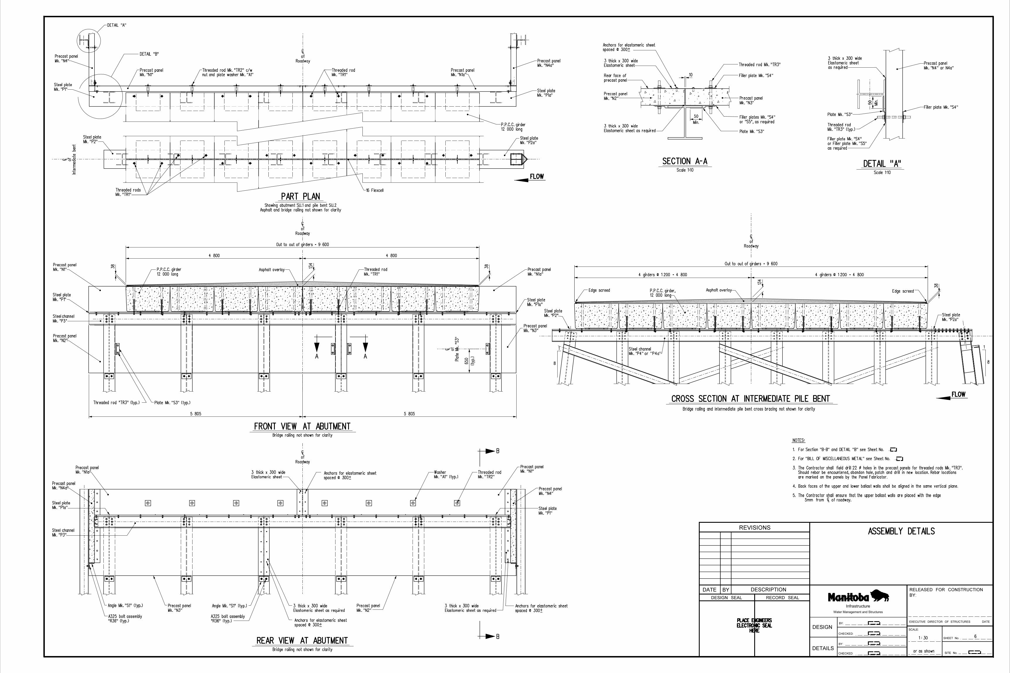
ASSEMBLY DETAILS
1 : 30
DETAIL "A"
Mk. "N4"
Precast panel
Mk. "N4a"
Precast panel
Mk. "N1"
Precast panel
Mk. "N1a"
Precast panel
12 000 long
P.P.C.C. girder
Mk. "TR1"
Threaded rod
nut and plate washer Mk. "A1"
Threaded rod Mk. "TR2" c/w
DETAIL "B"
Asphalt overlay
A
Bridge railing not shown for clarity
Bridge railing not shown for clarity
Mk. "N1"
Precast panel
Mk. "TR2"
Threaded rod
A
Mk. "N4"
Precast panelMk. "N4a"
Precast panel
Mk. "N1a"
Precast panel
Scale 1:10
or "S5", as required
Filler plates Mk. "S4"
Plate Mk. "S3"
Filler plate Mk. "S4"
Threaded rod Mk. "TR3"
precast panel
Rear face of
Mk. "N2"
Precast panel
B
B
Scale 1:10
Plate Mk. "S3"
as required
or Filler plate Mk. "S5"
Filler plate Mk. "S4"
Filler plate Mk. "S4"
Mk. "N4" or N4a"
Precast panelRoadway
of
|
Roadway
of
|
Mk. "N2"
Precast panel
Intermediate bent
of
|
Mk. "TR1"
Threaded rods 16 Flexcell
Mk. "N3"
Precast panel
4 girders @ 1 200 = 4 800 4 girders @ 1 200 = 4 800
Out to out of girders = 9 600
134
38
Bridge railing and intermediate pile bent cross bracing not shown for clarity
Asphalt and bridge railing not shown for clarity
Showing abutment SU.1 and pile bent SU.2
Mk. "N3"
Precast panel
Mk. "P3"
Steel channel
Mk. "N1"
Precast panel
Mk. "N2"
Precast panel
12 000 long
P.P.C.C. girder
Mk. "TR1"
Threaded rod
Mk. "P1a"
Steel plate
Mk. "N3"
Precast panel
Plate
Mk. "S3"
of
|
Plate Mk. "S3" (typ.)
Mk. "N1a"
Precast panel
Roadway
of
|
Mk. "P1a"
Steel plateMk. "P1"
Steel plate
Mk. "P1"
Steel plate
spaced @ 300±
Anchors for elastomeric sheet
spaced @ 300±
Anchors for elastomeric sheet
spaced @ 300±
Anchors for elastomeric sheet
spaced @ 300±
Anchors for elastomeric sheet
Mk. "P1a"
Steel plate
Mk. "P3"
Steel channel
Mk. "P1"
Steel plate
DETAIL "A"
CROSS SECTION AT INTERMEDIATE PILE BENT
SECTION A-A
PART PLAN
FRONT VIEW AT ABUTMENT
REAR VIEW AT ABUTMENT
Mk. "TR3" (typ.)
Threaded rod
Threaded rod "TR3" (typ.)
Mk. "A1" (typ.)
Washer
Angle Mk. "S1" (typ.) Angle Mk. "S1" (typ.)
"R36" (typ.)
A325 bolt assembly
"R36" (typ.)
A325 bolt assembly
Elastomeric sheet
3 thick x 300 wide
as required
Elastomeric sheet
3 thick x 300 wide
Elastomeric sheet as required
3 thick x 300 wide
Elastomeric sheet
3 thick x 300 wide
Elastomeric sheet as required
3 thick x 300 wide
Elastomeric sheet as required
3 thick x 300 wide
6
FLOW
1
8
Edge screed Asphalt overlay Edge screed
1
8
12 000 long
P.P.C.C. girder,
Roadway
of
|
FLOW
134
4 8004 800
Out to out of girders = 9 600
38
38
Min.
50
Min.
50
5 8055 805
10
(typ.)
650
Mk. "P2a"
Steel plateMk. "P2"
Steel plate
Mk. "P2a"
Steel plateMk. "P2"
Steel plate
HERE
ELECTRONIC SEAL
PLACE ENGINEERS
or "P4a"Mk. "P4"
Steel channel
BY:
RELEASED FOR CONSTRUCTION
REVISIONS
BYDATE
DESIGN
DETAILS
SHEET No.
SITE No.
SCALE:
BY:
CHECKED:
BY:
CHECKED:
DATE
DESCRIPTION
RECORD SEALDESIGN SEAL
Water Management and Structures
Infrastructure
EXECUTIVE DIRECTOR OF STRUCTURES
5mm from | of roadway.
5. The Contractor shall ensure that the upper ballast walls are placed with the edge
4. Back faces of the upper and lower ballast walls shall be aligned in the same vertical plane.
are marked on the panels by the Panel Fabricator.
Should rebar be encountered, abandon hole, patch and drill in new location. Rebar locations
3. The Contractor shall field drill 22 ! holes in the precast panels for threaded rods Mk. "TR3".
2. For "BILL OF MISCELLANEOUS METAL" see Sheet No. .
1. For Section "B-B" and DETAIL "B" see Sheet No. .
NOTES:

Mk. "N1" or "N1a"
Precast panel
12 000 long
PP.C.C. girder,
Mk. "N4" or "N4a"
Precast panel
Angle Mk. "S1"
Plate
Mk. "S3"
of
|
Bridge railing not shown for clarity
Scale 1:10
Mk. "N1"
Precast panel
Mk. "N4"
Precast panel
Washers Mk. "A2"
Mk. "N2"
Precast panel
Scale 1:10
or as shown
ASSEMBLY DETAILS
1 : 30
Precast panel
Washer Mk. "A2"
Bolt Mk. "R34"
Bracket Mk. "S2"
Scale 1:10
Angle Mk. "S1"
Mk. "TR3"
Threaded rods
Mk. "TR2"
Threaded rod
Mk. "N1" or "N1a"
Precast panel
Washer Mk. "A1"
26 thick flexcell 13 mastic
Mk. "TR1"
Threaded rod
Scale 1:2
Asphalt overlay
12 000 long
PPCC girder,
and bolting complete
Grout after erection
12 000 long
PPCC girder,
this side
Torque from
lock washers
One pair Nord-Lock
as required
Shims Mk. "SH1" or "SH2"
Elastomeric bearing
Scale 1:10
CROSS SECTION ELEVATION
16 flexcell
13 mastic
Mk. "TR1"
Threaded rod
Grout
Elastomeric bearing
12 000 long
P.P.C.C girders
Mk. "N2" or "N3"
Precast panel
Bracket Mk. "S2"
Mk. "N2" or "N3"
Precast panel
Grout
spaced @ 300±
Anchors for elastomeric sheet
spaced @ 300±
elastomeric sheet
Anchors for
spaced @ 300±
elastomeric sheet
Anchors for
holes in channel
field drill 18 !
Bolts Mk. "R36"
Mk. "P1" or "P1a"
Steel plate
with grout after erection
Dowel holes to be filled
after erection
to be filled with grout
Unused dowel holes
perforated CSP
200 ! invert
with grout after erection
Dowel holes to be filled
Steel plate
PART SIDE ELEVATION
DETAIL OF LATERAL CONNECTION ANGLE DETAIL "B"
DETAILS AT INTERMEDIATE BENT
SECTION AT ABUTMENT
SECTION B-B
(two bolts for each connection)
A325 bolt assembly Mk. "R1"
washer Mk. "W1"
Structural flat
Mk. "R34"
A325 bolt
Mk. "R30" (typ.)
A325 bolt assembly
Mk. "R35" (typ.)
A325 bolt assemblies
Mk. "R36"
A325 bolt assembly
Mk. "R32" (typ.)
A325 bolt assembly
Mk. "TR3" (typ.)
Threaded rod
Mk. "R30" (typ.)
A325 bolt assembly
Mk. "R35" (typ.)
A325 bolt assembly
Mk. "P3"
Steel channel
Mk. "R36"
A325 bolt assembly
DETAIL "C"
DETAIL "C"
hot poured joint sealant (typ.)
Rout and seal with approved
25 Top of ashpalt
Joint
of
|
20
12
3 wide saw cut
DETAIL "C"Scale 1 : 1
elastomeric sheet
3 thick x 300 wide
additional sheets to fit if required.
Additional sheets to be placed as required. Field cut
Sheets to be bonded to pile or panel with approved adhesive.
(field cut length of sheet required for ballast wall piles).
to be installed on all wingwall and ballast wall piles
A minimum of 1 - 3 thick x 300 wide elastomeric sheet
NOTE:
Elastomeric sheets (typ.)
3 thick x 300 wide
Structural flat washer
elastomeric sheet
3 thick x 300 wide
elastomeric sheet
3 thick x 300 wide
joint sealant (structural)
Impregnated expanding
26 x 60
panels Mk. "N1" & "N1a"
under precastcontinuous
masonry pad
3 x 150 wide elastomeric
joint sealant (non-structural)
Impregnated expanding
13 x 40
Plain elastomeric pad
10 x 100
joint sealant (structural)
Impregnated expanding
16 x 60
7For location of SECTIONS "B-B" & "DETAIL B" see Sheet No. 6.
NOTE:
1 12
5
precast panels
10 between 150
13
25 25
25 (typ.)
Asphalt overlay
Mk. "P4" or "P4a"
Steel channel
Asphalt overlay
Mk. "P2" or "P2a"
Steel plate
Plate Mk. "S3" (typ.)
HERE
ELECTRONIC SEAL
PLACE ENGINEERS
BY:
RELEASED FOR CONSTRUCTION
REVISIONS
BYDATE
DESIGN
DETAILS
SHEET No.
SITE No.
SCALE:
BY:
CHECKED:
BY:
CHECKED:
DATE
DESCRIPTION
RECORD SEALDESIGN SEAL
Water Management and Structures
Infrastructure
EXECUTIVE DIRECTOR OF STRUCTURES
4. Impregnated expanding joint sealant shall be installed as per manufacturer's recommendations.
3. Apply galvalloy to all field welds & areas where galvanizing has been damaged.
2. When grouting dowel holes in girders, ensure that there is no grout between bottom of girder and bearing plate.
f) Fill counter bored holes with mastic filler after tightening bolts.
lubricated prior to bolting.
e) High strength bolts shall be tightened by the turn-of-nut method as per Bridge Specifications. Ensure nuts are
- Threaded rod Mk. "TR1" - one standard flat washer and structural lock washer and two hex. nuts.
d) GIRDER TO STEEL CAP
plate Mk. "S5" if required.
- Threaded rod Mk. "TR3" - two Filler plates Mk. "S4", one structural lock washer, two standard flat washers and two hex. nuts, Filler
- Threaded rod Mk. "TR2" - One standard flat washer, one structural lock washer, structural plate washer Mk. "A1" and one stainless steel hex. nut.
- Bolts Mk. "R34" - One F436 hardened washer and one structural plate washer Mk. "A2", no nuts.
- Bolts Mk. "R36" - Two F436 hardened washers and one Grade DH heavy hex. nut.
c) PRECAST PANELS
- Bolts Mk. "R35" - Two F436 hardened washers and one Grade DH heavy hex. nut.
- Bolts Mk. "R32" - One hardened bevel washer and one Grade DH heavy
- Bolts Mk. "R30" - One F436 hardened washer, one hardened bevel washer and one Grade DH heavy hex. nut.
b) STEEL CAP
one pair Nord-Lock washers and one Grade DH heavy hex. nut.
- Bolts Mk. "R1" - c/w one F436 hardened washer, one structural plate washer Mk."W1",
a) GIRDER LATERAL CONNECTION
1. RE: BOLTING
NOTES:
or as shown
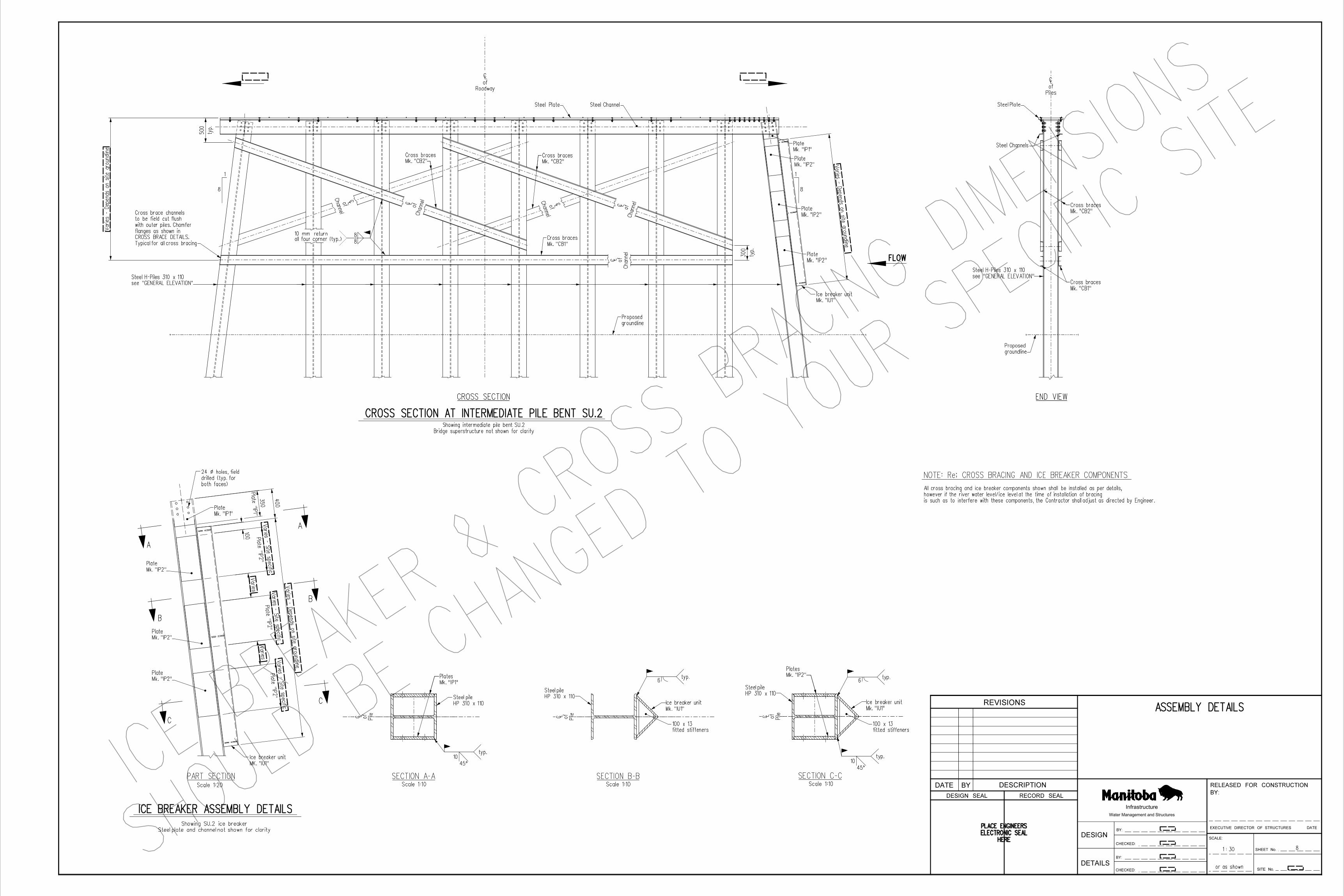
ASSEMBLY DETAILS
81 : 30
CROSS SECTION AT INTERMEDIATE PILE BENT SU.2
Bridge superstructure not shown for clarity
Showing intermediate pile bent SU.2
Steel Channel
Roadway
of
|
10
45°
typ.
HP 310 x 110
Steel pile
Mk. "IP1"
Plates
Pileof
| Pileof
| Pileof
|
SECTION A-A SECTION B-B SECTION C-CScale 1:10 Scale 1:10 Scale 1:10
PART SECTIONScale 1:20
Steel plate and channel not shown for clarity
Showing SU.2 ice breaker
CROSS SECTION END VIEW
Steel Plate
Steel Channels
see "GENERAL ELEVATION"
Steel H-Piles 310 x 110
Piles
of
|
see "GENERAL ELEVATION"
Steel H-Piles 310 x 110
Mk. "IP1"
Plate
Mk. "IP2"
Plate
Mk. "IP2"
Plate
FLOW
8
1
both faces)
drilled (typ. for
24 ! holes, field
Mk. "IP1"
Plate
Mk. "IP2"
Plate
Plate "IP1"
350
100
A
A
B
B
C
CHP 310 x 110
Steel pile
6typ.
HP 310 x 110
Steel pile
Mk. "IP2"
Plates
typ.6
typ.10
45°
8
1
Steel Plate
Mk. "CB1"
Cross braces
Mk. "CB2"
Cross braces
Channel
of|
Channel
of|
8
8
Mk. "CB2"
Cross braces
Channel
of|
Mk. "CB1"
Cross braces
Mk. "CB2"
Cross braces
Channel
of
|
Channel
of|
typ.
300
Typical for all cross bracing
CROSS BRACE DETAILS.
flanges as shown in
with outer piles. Chamfer
to be field cut flush
Cross brace channelsty
p.
500
groundline
Proposed
groundline
Proposed
HERE
ELECTRONIC SEAL
PLACE ENGINEERS
Mk. "IP2"
Plate
Mk. "IP2"
Plate
Mk. "IP2"
Plate
fitted stiffeners
100 x 13
fitted stiffeners
100 x 13
ICE BREAKER ASSEMBLY DETAILS
all four corner (typ.)10 mm return
Varie
s - Depends on site gro
undline
Varies - Depends on site groundlin
e
Varie
s - Depends on site gro
undline
400
Plate "IP2"
Varie
s - Site specific
Plate "IP2"
Varie
s - Site specific
Plate "IP2"
Varie
s - Site specific
Varie
s
Varie
s
Mk. "IU1"
Ice breaker unitMk. "IU1"
Ice breaker unit
MK. "IU1"
Ice breaker unit
SHOULD
BE C
HANGED
TO YOUR
SPECIFI
C SIT
E
ICE B
REAKE
R &
CROSS
BRACING
DIMENS
IONS
Mk. "IU1"
Ice breaker unit
BY:
RELEASED FOR CONSTRUCTION
REVISIONS
BYDATE
DESIGN
DETAILS
SHEET No.
SITE No.
SCALE:
BY:
CHECKED:
BY:
CHECKED:
DATE
DESCRIPTION
RECORD SEALDESIGN SEAL
Water Management and Structures
Infrastructure
EXECUTIVE DIRECTOR OF STRUCTURES
NOTE: Re; CROSS BRACING AND ICE BREAKER COMPONENTS
is such as to interfere with these components, the Contractor shall adjust as directed by Engineer.
however if the river water level/ice level at the time of installation of bracing
All cross bracing and ice breaker components shown shall be installed as per details,

PLAN
25 ! erection hole 25 ! erection hole
10 ! Nelson studs
18 ! holes
18 ! hole (typ.)
CROSS SECTION
Scale 1:10
PL 32 x 550
PLAN
19 ! hole, top flange only (typ.)
FOR ABUTMENTS
ELEVATION
CROSS SECTION
C310 x 45
FOR INTERMEDIATE PILE BENTS
PLAN
PLAN
19 ! hole, top flange only (typ.) 45
600 800 400 800 400 800 400 800
11 400
ELEVATION
5 400 6 000
75
75
75
152
75
1
8
75
1
8
Scale 1:10
CROSS SECTION
45
100100100100
Scale 1 : 20
or as shown
Scale 1:5
STEEL PILE CAP DETAILS
STEEL CHANNEL MK "P3"
STEEL PLATE MK "P1" & "P1a"
9
Roadway
of
|
Roadway
of
|
Pile
of
|Pile
of
|
Pileof
|
Channel
of
|
drilled (typ.)
24 ! holes, field
drilled (typ.)
24 ! holes, field
Channel
of
|
Pile
of
|
Pile
of
|
Pile
of
|
Roadway
of
|
Pile
of
|
Pile
of
|
Pile
of
|
10 ! x 19 long (typ.)
no thread stud
Nelson Type NBL
C'bore 45 !, 12 deep (typ.)
18 ! hole10 ! x 19 long (typ.)
no thread stud
Nelson Type NBL
Roadway
of
|
10 ! Nelson studs
18 ! holes
6 000
100100
400800400800400800400400
9 Spaces @ 100 = 900400800400800400800400800
199
199
250
250
500
PL 32 x 500
10 ! x 19 long (typ.)
no thread stud
Nelson Type NBL
215215
250250
199199
CROSS SECTIONScale 1:5
1 200
10 ! x 19 long (typ.)
no thread studs
Nelson Type NBL
18 ! hole (typ.) 25 ! erection hole
1 200STEEL PLATE MK "P2"
PLAN
1 200
10 ! x 19 long (typ.)
no thread studs
Nelson Type NBL
25 ! erection hole
1 200
25 ! erection hole
800 400 800 400 800 400 800 400 9 Spaces @ 100 = 900
1 400 1 400 1 400 700 700 1 400 1 400 1 400 900
Pile
of
|
Pile
of
|
Pile
of
|
Pile
of
|
Pile
of
|
Pile
of
|
18 ! hole (typ.) PL 32 x 500
199
199
500
250
250
10 ! Nelson studs
18 ! holes
400 800 400 800 400 800 400 400
100100600 800 400 800 400 800 400 800
5 400
25 ! erection hole
250 250
199 199
215 215
10 ! x 19 long (typ.)
no thread stud
Nelson Type NBL
CROSS SECTIONScale 1:5
STEEL PLATE MK "P2a"
1 200
275
1 200
1001009 Spaces @ 600 = 5 400
5 800
380
105
398
550
398 105
380
100100100100
75
75
75
152
45
45
400 800 400 800 400 800 400 400
9 Spaces @ 600 = 5 400 9 Spaces @ 600 = 5 400
5 800 5 800
11 600
2 100 2 100 1 050 1 050 2 100 2 100
C310 x 45
STEEL CHANNEL MK "P4" & "P4a"Channel Mk. "P4" as shown, Channel Mk. "P4a" opposite hand
Plate Mk. "P1" as shown, Plate Mk. "P1a" opposite hand
HERE
ELECTRONIC SEAL
PLACE ENGINEERS
75 typ.
75 (typ.)
75 (typ.)
75 typ.
BY:
RELEASED FOR CONSTRUCTION
REVISIONS
BYDATE
DESIGN
DETAILS
SHEET No.
SITE No.
SCALE:
BY:
CHECKED:
BY:
CHECKED:
DATE
DESCRIPTION
RECORD SEALDESIGN SEAL
Water Management and Structures
Infrastructure
EXECUTIVE DIRECTOR OF STRUCTURES

BY:
RELEASED FOR CONSTRUCTION
REVISIONS
BYDATE
DESIGN
DETAILS
SHEET No.
SITE No.
SCALE:
BY:
CHECKED:
BY:
CHECKED:
DATE
DESCRIPTION
RECORD SEALDESIGN SEAL
Water Management and Structures
Infrastructure
EXECUTIVE DIRECTOR OF STRUCTURES
400 200 200 400
1 : 5
or as shown
18 ! holes
FRONT VIEW
Angle 152 x 152 x 13
END VIEW
100
100
300
A
18 ! holes
75
285
60
PL 13 x 285 x 300
PL 13 x 110 x 250
FRONT VIEW END VIEW
PL 13 x 285 x 300
PL 13 x 110 x 250
A
SECTION A-A
6
6
FRONT VIEW END VIEW
25 ! holes
22 x 40 slotted holes
80
6
132
15
15
21
300
22 ! holes Plate, 10 thick
75
150
75
150
14 ! holes Plate, 10 thick 22 ! holes
45
90
45
90
90 45
180
80
26 ! slots
5 mm thick for "SH2"
Plate - 2.5 mm thick for "SH1"
PL 13 x 285 x 300
PL 13 x 110 x 250
STEEL PILE CAP DETAILS
SHIM PLATES Mk. "SH1" & "SH2"WASHER Mk. "A2"WASHER Mk. "A1"FILLER PLATES Mk. "S4" & "S5"
BRACKET Mk. "S2"
PLATE Mk. "S3"ANGLE Mk. "S1"
10
13060
250
75
25
25
250
13
130
60
250
110
35 10
227
20050
300
20050
50
100
27
40
HERE
ELECTRONIC SEAL
PLACE ENGINEERS
100 x 13 fitted stiffeners
Angle 203 x 203 x 13
END VIEWScale 1:10
6
SIDE ELEVATIONScale 1:10
DETAIL "A" DETAIL "A"
PLAN
ELEVATIONScale 1:10
CROSS BRACES Mk. "CB1" & "CB2"
CB1
CB2
END VIEW
DETAIL "A"Scale 1:5
Scale 1:10
Scale 1:10
40
40
50 50 100
13
C200 x 21
Varies - Depends on site groundline Varies - Depends on site groundline
Varies - Depends on site groundline
Varies - Depends on site groundline
Varies - Depends on site groundline
SHOULD
BE C
HANGED
TO YOUR
SPECIFI
C SIT
E
ICE B
REAKE
R &
CROSS
BRACING
DIMENS
IONS
ICE BREAKER UNIT Mk. "IU1"
Mk. "S5" - 3 thick plate
Mk. "S4" - 6 thick plate

482.00
BEARING AND ERECTION DETAILS
1 : 75
or as shown
Girder
of
|
Girder
of
|
Girder
of
|
Girder
of
|
Girder
of
|
Girder
of
|
Road
way
of
|
Bearings
of
|
SU.1
A A
A A
SU.2
Hex. nut
Grout
Hex. nut
13 thick mastic filler
Grout
hole in girder
50 ! precast
Girder
of
|
Girder
of
|
SU.3
B B
Bearings
of
|
Bearings
of
|
Bearings
of
|
108 108
Bearing
of
|
Bearing
of
|
13 thick mastic filler
11 800 11 800
26 flexcell
8 8
girder & steel plate
No grout between
PLAN
SECTION "B-B"SECTION "A-A"
End of girder End of girder
(typ.)
Elastomeric bearing
Hex. nut
Hex. nut
joint sealant (structural)
Impregnated expanding
26 x 60
structural lock washer
Standard flat washer &
Bearing
Elastomeric
structural lock washer
Standard flat washer &
16 flexcell
Grout
joint sealant (structural)
Impregnated expanding
16 x 60
Bearing
Elastomeric
Bearing
Elastomeric
Pile
of
|
28
11
Scale 1:2
ELASTOMERIC BEARINGS
PLANScale 1:10
PART CROSS SECTION
Girder
of
|
Bearing
of
|
moulded into pad).
(2 - 3mm thick steel plates
30 mm thick elastomeric pad
plates moulded into pad
2 - 3mm thick steel
Scale 1:5
Threaded rods at SU.1 & SU.3. See sheet No. 6 for layout.
Scale 1:5
Threaded rods at SU.2. See Sheet No. 6 for layout.
Bridge & Pile Bent
of
|
Bridge & Pile Bent
of
|
80
300
600
75 15
0
36
36
30
1 200
1 200
1 200
600
600
1 200
1 200
1 200
100 100100
End of girder
Bearing
of
|
HERE
ELECTRONIC SEAL
PLACE ENGINEERS
NORTH or WEST SOUTH or EAST
5 (typ.)
Threaded rod Mk. "TR1"
Threaded rod Mk. "TR1"
Steel plate Steel plate
- All surcharge loads encroaching in this zone must be distributed over an area not less than 2.0 Ê.
- Perform all precautionary measures outlined by the Department as a result of that submission.
weights and locations of equipment including expected tipping forces on crane outriggers, etc.
- Submit a girder erection procedure for approval outlining type, configuration,
must be satisfied:
3. Should the Contractor propose to encroach on this zone, the following requirements
the depth of backfill to the bottom of the panels at the time of girder erection.
surcharge loads behind the back face of the precast panels within a distance equal to
2. Where possible, girder erection equipment shall be positioned such that there are no
minimized near the precast concrete ballast walls and wingwalls.
1. Surcharge loading on the backfill resulting from girder erection operations shall be
Re: Girder Erection Operations Behind Abutment Ballast Walls
NOTES:
BY:
RELEASED FOR CONSTRUCTION
REVISIONS
BYDATE
DESIGN
DETAILS
SHEET No.
SITE No.
SCALE:
BY:
CHECKED:
BY:
CHECKED:
DATE
DESCRIPTION
RECORD SEALDESIGN SEAL
Water Management and Structures
Infrastructure
EXECUTIVE DIRECTOR OF STRUCTURES
21 dia. hole in steel plate to match girders.
of holes in precast girders and grouted. Field drill
Threaded rods Mk."TR1", set exactly on centreline
NOTE :

RAILING LAYOUT AND DETAILS
B.A.N.
1 : 10K.P.
or as shown
SECTION B-B
SECTION A-A
TYPICAL SECTION
ELEVATION C-C DETAIL "A"
TYPICAL OF CONTINOUS RAILS
Scale 1:5
Showing dege screed installation detail.Showing edge screed installation detail.
Scale 1:5
RAIL END CONNECTION
Railpost
of
|
Edge screed retainer
C
Not to Scale
TYPICAL AT PILE BENT
Railpost
of
|
Railpost
of
|
C
HERE
ELECTRONIC SEAL
PLACE ENGINEERS
RAILING LAYOUT
APPROACH RAIL CONNECTION DETAILS
RAILING ERECTION DETAILS
RAILPOST ERECTION DETAILS
12
B B
A
A
ELEVATION
BY:
RELEASED FOR CONSTRUCTION
REVISIONS
BYDATE
DESIGN
DETAILS
SHEET No.
SITE No.
SCALE:
BY:
CHECKED:
BY:
CHECKED:
DATE
DESCRIPTION
RECORD SEALDESIGN SEAL
Water Management and Structures
Infrastructure
EXECUTIVE DIRECTOR OF STRUCTURES
a maximum of 12 mm with shims Mk. "RS3" & "RS4".
2. High strength bolted connection may be shimmed to
For quantities see Bill of Miscellaneous Metal on Girder sheet.
These bolts to be supplied by the Girder Fabricator.
tightened by turn-of-nut method as per Specification 1061.
1. High strength bolts Mk. "R27" & "R28" shall be
NOTES:
2. This sheet to be read in conjunction with Sheets & .
1. All railposts shall be Mk. "GP1" unless noted otherwise.
NOTES:
A
B
thrie beam
Approach guardrailing
terminal connector
Thrie beam
& lock washer
c/w flat washer
Bolts Mk. "C7"
& lock washer
c/w flat washer
Bolts Mk. "C2"
& lock washer
c/w flat washer
Bolts Mk. "C4"
& lock washer
c/w flat washer
Bolts Mk. "C6"
Mk."CP1"
Connection plate
& lock washer
c/w flat washer
Bolts Mk. "C3"
Railpost Mk. "GP2"
Railpost Mk. "GP2"
& lock washer
c/w flat washer
Bolt Mk. "C4"
& lock washer
c/w flat washer
Bolt Mk. "C5"
Mk. "CA1"
Connection angle
timber block
Approach guardrailing
timber post
Approach guardrailing
thrie beam
Approach guardrailing
& lock washer
c/w flat washer
Bolt Mk. "C7"
Mk."CP1"
Connection plate
terminal connector
Thrie beam
Flat washers (typ.)
55Bolts Mk. "C1" (typ.)
or "SB1"
Sleeve Mk. "ST1"
Flat washers (typ.)
Bolts Mk. "C1" (typ.)5
20°C
20 @
as required
Shims Mk. "RS1" & "RS2"
(HSS 203 x 102 x 6.4)
Top Rail
Bolts Mk. "C1"
as required
Shims Mk. "RS3" & "RS4"
Bolt Mk. "C1"
(HSS 102 x 102 x 6.4)
Bottom Rail
DETAIL "A"
as required (Max. 4)
Shims Mk. "RS5"
as required (Max. 4)
Shims Mk. "RS3"
C
Washer Mk. "A"
Bolt Mk. "R28"
Hardened washer
Washer Mk. "BB1"
Bolt Mk. "R27"
Bolt Mk. "C6"
Edge screed retainer
L38 x 38 x 4.8
Edge screed
L38 x 38 x 4.8
Edge screed
& lock washer
c/w flat washer
Bolts Mk. "C6"
Edge screed retainer
or "GP2"
Railpost Mk. "GP1"
Flat washer (typ.)
Rail Bolts Mk. "C1" (typ.)
Flat washers (typ.)
Rail5 5
Bolts Mk. "C1" (typ.)
or "SB2"
Sleeve Mk. "ST2"
Rail
GP2
SU.1
B4
T2
SB2
END SPAN
RAILS SLEEVES RAILPOSTS
GP1
2 2 2
GP2ST2 SB2T1
2
T2 B4
2 12 2
B1
2
ST2 ST1T1
B1 SB1 B5
T3
SU.2
RAILS SLEEVES
2 2 2
ST1 SB1T3 B5
2
B1
T1 ST2
SB2
T2
END SPAN
RAILS SLEEVES RAILPOSTS
GP1
2 2 2
GP2ST2 SB2T1
2
T2 B4
2 12 2
B1
2
B4
SU.3
GP2

BY:
RELEASED FOR CONSTRUCTION
REVISIONS
BYDATE
DESIGN
DETAILS
SHEET No.
SITE No.
SCALE:
BY:
CHECKED:
BY:
CHECKED:
DATE
DESCRIPTION
RECORD SEALDESIGN SEAL
Water Management and Structures
Infrastructure
EXECUTIVE DIRECTOR OF STRUCTURES
103
50
HSS 203 x 102 x 6.4
slotted hole (typ.)
21 x 40receive 19 ! bolt
Tapped hole to
Plate, 12 thick typ.
44
88
95
190
18
18
45 45
slotted hole (typ.)
21 x 40
45 45
5(typ.)
Each side
see detail
End plate
1 8501 850423
5 968
6 45 45
160 40
slotted hole (typ.)
21 x 40
45 45
typ.
21
40160
slotted hole (typ.)
21 x 40
891
40 160
typ.
21
45 45
16040
5 540
1 8501 845
45 45
slotted hole (typ.)
21 x 40
HSS 102 x 102 x 6.4
typ.Plate, 12 thick
44
88
44
88
18
18
receive 19 ! bolt
Tapped hole to
(typ.)
slotted hole
21 x 80
(typ.)
slotted hole
21 x 170
205 205
*
205 205
916300
1 516
(typ.)
slotted hole
21 x 40
600
300
160 45 45 160
typ.
21
6
45°
G
R=18 (typ.)
Plate 8 thick
6
45°
G
82
82
*
1 516
916300
103
160 45 45 160
38
typ.
21
(typ.)
slotted hole
21 x 80
160 45 45 160
(typ.)
slotted hole
21 x 40
600
300
160 45 45 160
103
typ.
21
38
6
45°
G
Plate 8 thick
6
45°
G
80
103
38
180
80
103
38
180
R=18 (typ.)
160 40
slotted hole (typ.)
21 x 40
45 45
typ.
21
40160
slotted hole (typ.)
21 x 40
891
16040
typ.
21
891
16040
typ.
21
7 390
1 8501 8501 845
16040
7 390
1 8501 8501 845
16040
15
slotted hole (typ.)
21 x 40
45 45
typ.
21
B45
see detail
End plate
(typ.)
Each side45 45
1 850423
4 118
150
4. All dimensions are in millimeters (mm).
3. The width and height of the sleeves shall not exceed the dimensions shown.
2. The length of slotted holes shall not be less than shown.
1. It is imperative that all rail and sleeve holes in each pair of holes be opposite to each other.
NOTES:
B.A.N.
K.P.
or as shown
RAILING DETAILS
1 : 7.5
Mk. "T2"
Mk. "B4"
Rail
of
|
Mk. "ST2"TYPICAL CROSS SECTION
Mk. "SB2" TYPICAL CROSS SECTIONScale 1:5
Rail
of
|
TYPICAL CROSS SECTION END PLATE
TYPICAL CROSS SECTION END PLATE
Rail
of
|
Mk. "B1"
Rail
of
|
Rail
of
|
Mk. "B5"
Mk. "T1"
Mk. "T3"
Mk. "ST1"NOTE: * Approx. 300 mm
Mk. "SB1"NOTE: * Approx. 300 mm
Rail
of
|
HERE
ELECTRONIC SEAL
PLACE ENGINEERS
Scale 1:5
Typical for rails Mk. "T1", "T2", & "T3"
Scale 1:5
Typical for rails Mk. "T2"
Scale 1:5
Typical for rails Mk. "B1", "B4" & "B5"
Scale 1:5
Typical for rails Mk. "B4"
DETAILS OF TOP RAILS
DETAILS OF BOTTOM RAILS
DETAILS OF SLEEVES
13
Scale 1:5
103
50
103
50
103
50

BY:
RELEASED FOR CONSTRUCTION
REVISIONS
BYDATE
DESIGN
DETAILS
SHEET No.
SITE No.
SCALE:
BY:
CHECKED:
BY:
CHECKED:
DATE
DESCRIPTION
RECORD SEALDESIGN SEAL
Water Management and Structures
Infrastructure
EXECUTIVE DIRECTOR OF STRUCTURES
5 - 24 ! holes
B B
8 - 21 ! holes20347
800
3290
130350
61
194
194
480
270
75
598
97
97
158
45
45
250
103
40
236
267
560
45
1212
12
Plates, 5 thick
slotted hole
16 x 21
30
30
150
3
95
50
130
Plate, 16 thick
24 ! hole
100
50
309030
150
102
12
R=25
R=25
80
252
(typ.)
24 ! holes
Angle 102 x 102 x 9.5
550
50
61
194
194
50
301
129
21 (t
yp.)
22 ! slots
- 5 thick for "RS4"
Plate - 3 thick for "RS3"
38
100
309030
150
Plate, 8 thick
21 ! hole
30
60
30
60
24 ! slots
Plate, 3 thick
48
140
309030
150
22 ! slots
- 5 thick for "RS2"
Plate - 3 thick for "RS1"
190
309030
150
28
200 long
Plate 8 x 138,
AA
Post, W150 x 3078
350
50
270
200
slotted holes
10 - 21 x 24
slotted hole
16 x 30
in both flanges
slotted holes
25 x 50
slotted holes
22 x 50
250
103
40
236
268
4545
1 235
540
315
55
200 long
Plate 8 x 138,
AA
Post, W150 x 30
270
200
slotted holes
6 - 21 x 24
slotted hole
16 x 30
in both flanges
slotted holes
25 x 50
slotted holes
22 x 50
4545
250
103
40
540
1 235
315
55
5typ.
200 long
Plate 8 x 138,
7
B.A.N.
1 : 5K.P.
or as shown
RAILPOST DETAILS
| |
AA
Typical for railposts Mk. "GP1" & "GP2"
B B
ELEVATION
SECTION B-B
Mk. "CP1" shown, Mk. "CP2" opposite hand.NOTE:
Mk. "CA1" shown, Mk. "CA2" opposite hand.NOTE:
R=25
HERE
ELECTRONIC SEAL
PLACE ENGINEERS
RAILPOST MK. "GP1" RAILPOST MK. "GP2"SHIMS MK. "RS1" & "RS2"
WASHER MK. "BB1"
WASHER MK. "A"SECTION A-A
SHIMS MK. "RS3" & "RS4"
EDGE SCREED RETAINER
CONNECTION ANGLES MK. "CA1" & "CA2"
CONNECTION PLATES MK. "CP1" & "CP2"
SHIM MK. "RS5"
14
AA

PLAN
EXTERIOR ELEVATION
Exterior face
|
AA
PLAN
DETAIL "A"
A A
PLAN
ELEVATION
girder before destressing
Represents top surface of
|
line
Reference
line
Reference
camber curve
End of reverse
|
0° to 45
°
ELEVATION
DETAIL "B"
camber curve
End of reverse
camber on top surface after destressing
Showing variable depth of girder to eliminate
B
B
B
B
refer to this point
Dimensions shown on "PLAN"
Mk. "S7"
Girder end angle
Scale 1:15
C
Railpost
of
|
C
Scale 1:15
Scale 1:5
ELEVATION SECTION C-C
Scale 1 : 40
Scale 1:5
ELEVATION SECTION D-D
unit Mk. "U1"
Railpost anchor
unit Mk. "U1"
Railpost anchor
unit Mk. "U2"
Railpost anchor
concrete
Blockout in
concrete
Blockout in
D
D
exaggerated reverse camber profile
Top of form showing
unit Mk. "U2"
Railpost anchor
Girder end angle Mk. "S7"
50 ! holes 50 ! holes
50 ! holes 50 ! holes
girder before destressing (level)
Represents bottom surface of
PRECAST PRESTRESSED CHANNEL GIRDER DETAILS
Ferrule loop insert
Ferrule loop insert
Scale 1:15
Typical at both ends of girders
Top surface of girder shall be screeded perpendicular to side formsNOTE:
Lateral connection
of
|
Vertical face
POINT "C" on curve because of various skew angles.
The end of girder will fall between POINT "A" andNOTE:
END VIEWSECTION B-BSECTION A-A
EXTERIOR GIRDER MK. "G1"
INTERIOR GIRDER MK. "G2"
GIRDER CONCRETE DETAILS
DETAIL "B"
DETAIL "A"
Mk. "S7"
Girder end angleMk. "S7"
Girder end angle
Mk. "S7"
Girder end angleMk. "S7"
Girder end angle
Girder
of
|
Girder
of
|
Girder
of
|
Chamfer all edges
Mk. "LC1"
Lateral connection angle
Mk. "LC1"
Lateral connection angle
G1
C. to c. of railpost anchor units Mk. "U1" & "U2"
6 000 6 000
12 000
225
225
1 200
100
1 800 1 800
3 6003 6003 600
100
6 000 6 000
12 000
1 800 1 800
3 6003 6003 600
225
225
1 200
100 100
Girder
1 200
1 000 1 000 1 000 1 000 1 000 1 000 1 000 1 000 1 000 1 000 1 000 1 000
6 0006 000
600 600
(end @ 45°)
1 200
Varies
600 600
(end @ 45°)
1 200
684
678
669
3 Spaces @ 1 850 = 5 550 3 Spaces @ 1 850 = 5 550
800
1 100
206 206
1 200 1 200
600
300
Varies
530
530
50
50
50
50
650
50
50
30 150 150 30
Varies
5012
0
45 45
125 125
45 45
25
9090
150150
120
90
110
662
657
650
653
651
651
653
657
662
669
678
684
3030
85
315
60
C. to c. of lateral connections
C. to c. of lateral connections
4 900 4 900
4 900 4 900
90°
HERE
ELECTRONIC SEAL
PLACE ENGINEERS
20 chamfer (typ.)
20 chamfer (typ.)
20 chamfer (typ.)
typ.
top edges only
6 mm radius
BY:
RELEASED FOR CONSTRUCTION
REVISIONS
BYDATE
DESIGN
DETAILS
SHEET No.
SITE No.
SCALE:
BY:
CHECKED:
BY:
CHECKED:
DATE
DESCRIPTION
RECORD SEALDESIGN SEAL
Water Management and Structures
Infrastructure
EXECUTIVE DIRECTOR OF STRUCTURES
A B C D E F G H I H G F E D C B A
A B C D E F G H I H G F E D C B A
A B C D E F G H I H G F E D C B A
7. Approximate mass per girder = 12 000 kg
Cross section 2 mm ±
6. Girder dimensioning tolerances: Length 3 mm ±
Jacking force/strand, fpj = 128.5 kN/strand
Minimum ultimate strength, fpu = 1 860 MPa
5. Prestressing steel: 13 mm ! low relaxation strands
@ 28 days, f'c = 45 MPa
4. Concrete strength: @ transfer, f'ci = 35 MPa
3. Design distribution factor = 0.5 lanes/girder.
AASHTO LRFD "HL-93"
2. Design Vehicular Live Load: Modified AASHTO HSS-25
Specifications, First Edition, 1994 plus 1996/1997 interim's.
1. Design in accordance with AASHTO LRFD Bridge Design
:NOTES

BY:
RELEASED FOR CONSTRUCTION
REVISIONS
BYDATE
DESIGN
DETAILS
SHEET No.
SITE No.
SCALE:
BY:
CHECKED:
BY:
CHECKED:
DATE
DESCRIPTION
RECORD SEALDESIGN SEAL
Water Management and Structures
Infrastructure
EXECUTIVE DIRECTOR OF STRUCTURES
ELEVATION
Scale 1 : 20
or as shown
END VIEW
20 - 13 ! Low Relaxation straight strands
3 500 each end
2 Debonded strands
PART PLANScale 1:5
E EEnd of girder
0.8 %
bottom of girder
Recessed area in
SECTION E-E
PRECAST PRESTRESSED CHANNEL GIRDER DETAILS
Typical at both ends of girders
surface and grout after installation).
pockets (cut off min. 25 mm below top
adequate lifting devices c/w 50 deep
for the design, supply and installation of
The girder fabricator shall be responsible
BEARING RECESS DETAILS
GIRDER STRAND LAYOUT Low Relaxation straight strands
Typical layout of 20 - 13 !
Bottom of girder
G2
See End View
3 500 debonded
See End View
3 500 debonded
req'd
As
75 50 7550
100
50
2@
50
100
275
650
275
500 37 500
HERE
ELECTRONIC SEAL
PLACE ENGINEERS

BY:
RELEASED FOR CONSTRUCTION
REVISIONS
BYDATE
DESIGN
DETAILS
SHEET No.
SITE No.
SCALE:
BY:
CHECKED:
BY:
CHECKED:
DATE
DESCRIPTION
RECORD SEALDESIGN SEAL
Water Management and Structures
Infrastructure
EXECUTIVE DIRECTOR OF STRUCTURES
A
A B
B
Scale 1 : 5
or as shown
C
C
D
D
| |
|
|
|
E
E
PRECAST PRESTRESSED CHANNEL GIRDER DETAILS
void behind nut
capped to create a 20 deep
insert metal or plastic tube,
Prior to concrete placement
void behind nut
capped to create a 20 deep
insert metal or plastic tube,
Prior to concrete placement
RAILPOST ANCHOR UNIT MK. "U1" RAILPOST ANCHOR UNIT MK. "U2"
GIRDER END ANGLE MK. "S7"
LATERAL CONNECTION ANGLE MK. "LC1"
headed stud anchor (Typ.)
10 ! x 100
Plate 3 thickPlate 3 thick
Plate 3 thick
headed stud anchor
10 ! x 100
headed stud anchor
19 ! x 200
headed stud anchor
19 ! x 125
L89 x 64 x 9.5
L76 x 76 x 6.4
L76 x 76 x 6.4
headed stud anchor (Typ.)
19 ! x 200 long
headed stud anchor (Typ.)
19 ! x 125 long
slotted holes
24 x 50
Scale 1:2 Scale 1:2
3Typ.
2
L152 x 152 x 13
24 ! holes
headed stud anchor
19 ! x 150
L152 x 152 x 13
Plate, 13 thick
21 ! holes
anchors, Type D2L (Typ.)
Nelson deformed bar
anchor, Type D2L
Nelson deformed bar
headed stud anchor (Typ.)
19 ! x 150 long
headed stud anchor (Typ.)
10 ! x 100
24 ! hole
centered on
for 22 ! bolt,
Heavy hex nut
on 21 ! hole
19 ! bolt centered
Heavy hex nut for
21 ! hole (Typ.)
19 ! bolt centered
Heavy hex nut for
24 ! hole (Typ.)
22 ! bolt, centered
Heavy hex nut for
Plate, 13 thick Plate, 13 thick
headed stud anchor (Typ.)
10 ! x 100
L152 x 152 x 13
anchor, Type D2L
Nelson deformed bar
3 - 19 ! x 600 long
Nut
Weld
Seal
Nut
Weld
Seal
G3
125125
4545
250 125125
809080
60
110
60
125125
4545
250
50
100
9090 4545
9090
125125
50
50
125475475125
3 3
1 200
75
75
45°
50
45
40
5°
4545
150150
300
5050
125125
45°
HERE
ELECTRONIC SEAL
PLACE ENGINEERS
SECTION E-E END VIEW
PLAN
SIDE VIEW ELEVATION
SECTION A-A SECTION D-DSECTION C-CSECTION B-B
FRONT VIEW REAR VIEWREAR VIEWFRONT VIEW
PLAN VIEW

Scale 1 : 20
or as shown
B.A.N.
K.P.
HEREELECTRONIC SEALPLACE ENGINEERS
PRECAST PRESTRESSED CHANNEL GIRDER DETAILS
G4
B
B
175
175
5 spaces
@ 17
0 = 850
60 70
=320
2@160 30025040 spaces @ 250 = 10 000250300
=320
2@160
70 60
D D
300
A
A
1503 spaces @ 300 = 900150
150
225
400
A
A
300
=200
2@10
0200
SECTION B-B
SECTION A-A
DETAIL AT RAILPOST ANCHOR
100 cl. 100 cl.
35 cl.
850
50 cl. 50 cl.
850
100
35 cl. 35 cl.
Scale 1:10
unit Mk. "U1"
Railpost anchor
unit Mk. "U2"
Railpost anchor
|
placement of railpost anchors.
be adjusted slightly to allow accurate
: Reinforcing steel placement mayNOTE
Bars Mk. 1501_G1
& 15
03_
G1
Bars
Mk. 15
02_
G1
Bars Mk. 1002_G1
Mk. 10
04_
G1
Bars
Bars Mk. 1002_G1
Mk. 10
01_
G1
Bars
Bars Mk. 1003_G1
Bars
Mk. 15
02_
G1
PART SECTION D-D
C
CC
C
END VIEW C-C
ELEVATION OF GIRDER
PLAN OF GIRDER
BY:
RELEASED FOR CONSTRUCTION
REVISIONS
BYDATE
DESIGN
DETAILS
SHEET No.
SITE No.
SCALE:
BY:
CHECKED:
BY:
CHECKED:
DATE
DESCRIPTION
RECORD SEALDESIGN SEAL
Water Management and Structures
Infrastructure
EXECUTIVE DIRECTOR OF STRUCTURES
1503_G1
1502_G1
1501_G1
1002_G1
1001_G1
1001_G1
1003_G1
1003_G1
1503_G1
1503_G1
1502_G1
1501_G1
1002_G1
1001_G1
1001_G1
1003_G1
1003_G1
1503_G1
1001_G1
1002_G1
1003_G1
1502_G1
1001_G1
1003_G1
1503_G1
1004_G1
1501_G1
1003_G1
1004_G1
1501_G1
1503_G1
1001_G1
1003_G1
See Bill of Reinforcing Sheet No. G .
3. Bar Mark labels with suffix _G1 are Exterior girders and suffix _G2 are Interior girders.
2. Reinforcing details are typical for all 12 m girders unless noted otherwise.
1. Concrete cover shall be 25 mm unless noted otherwise.
NOTES:

BY:
RELEASED FOR CONSTRUCTION
REVISIONS
BYDATE
DESIGN
DETAILS
SHEET No.
SITE No.
SCALE:
BY:
CHECKED:
BY:
CHECKED:
DATE
DESCRIPTION
RECORD SEALDESIGN SEAL
Water Management and Structures
Infrastructure
EXECUTIVE DIRECTOR OF STRUCTURES
MARK TYPE LENGTH
BENDING DIAGRAMDIAMETER
PIN
TYPE
GIRDER
TYPE
PER GIRDER
of BARS
TOTAL No.
GIRDERS
No. of
PER GIRDER
BARS
No. of
SITE No.BILL OF REINFORCING STEEL - 12 M GIRDERS
G1 4 8 3245 4 0801001_G1 BENT
1 500
1 080
1 500
G1 4 10 4045 3 6501002_G1 BENT
140 140
600
600
440
240
1 100
440
240
R= R=
G1 4 8 3245 2 9501003_G1 BENT
100
740
570
760
540
150320
630
G1 4 4 161 0001004_G1 STR
G1 4 41 16465 2 4401501_G1 BENT
1 000
570
150
G1 4 8 3210 3001502_G1 STR
G1 4 12 481 1001503_G1 STR
G2 12 8 9645 4 0801001_G2 BENT
1 500
1 080
1 500
G2 12 10 12045 3 6501002_G2 BENT
140 140
600
600
440
240
1 100
440
240
R= R=
B
DK
DH
C
DD
Total volume of structural concrete per exterior girder Ë
Total volume of structural concrete per interior girder Ë
5. All bars shall be bent in accordance with the following detail :
All other items to be identified in a similar fashion.
4. Like bars shall be bundled, securely tied and identified as to Mark and Site No. by appropriate means.
unless noted otherwise in the BILL OF REINFORCING STEEL.
3. All reinforcing steel shall conform to CSA G30.18-M92 "Billet Steel Bars for Concrete Reinforcement" Grade 400W,
2. All reinforcing steel shall be deformed steel, unless noted otherwise in the BILL OF REINFORCING STEEL.
of C.S.A. A23.1-04, unless noted otherwise in the BILL OF REINFORCING STEEL.
"Manual of Standard Practice". Radii are inside dimensions. All reinforcing steel bends and hooks shall conform to Clause 6.6.2
on 90°, 135° & 180° hooks are the "A" or "G" dimensions for standard 90°, 135° & 180° hooks referenced from the RSIC
1. All dimensions given in bending diagram are out to out, except radii and extensions on 90°, 135° & 180° hooks. Extensions
NOTES:
MARK TYPE LENGTH
BENDING DIAGRAMDIAMETER
PIN
TYPE
GIRDER
TYPE
PER GIRDER
of BARS
TOTAL No.
GIRDERS
No. of
PER GIRDER
BARS
No. of
SITE No.BILL OF REINFORCING STEEL - 12 M GIRDERS
G2 12 8 9645 2 9501003_G2 BENT
100
740
570
760
540
150320
630
G2 12 4 481 0001004_G2 STR
G2 12 41 49265 2 4401501_G2 BENT
1 000
570
150
G2 12 8 9610 3001502_G2 STR
G2 12 12 1441 1001503_G2 STR
B.A.N.
K.P.
3 660
HEREELECTRONIC SEALPLACE ENGINEERS
PRECAST PRESTRESSED CHANNEL GIRDER DETAILS
4.94
4.93
G5
3 660

1 : 20K.P.
B.A.N.
or as shown
150
5 800
75 ! holes
3 Spaces @ 1 200 = 3 600 595
700
320 R
ear fa
ce
3@18
0=540
80
80
100
70
90
18 Spaces @ 300 = 5 400200
150
400
150
6 850
150
1 300
18521 Spaces @ 300 = 6 300185
3 Spaces
@ 280 = 840
265
125
3 Spaces
@ 280 = 840
265
125
Rear fa
ce
70
4 750
150
1 300
18514 Spaces @ 300 = 4 200185
3 Spaces
@ 280 = 840
265
125
70
90 90
70
125
265
3 Spaces
@ 280 = 840
Rear fa
ce
5 000
150
2 000
6 Spaces
@ 260 = 1 560
245
125
Rear fa
ce
885
70
Formed fa
ce
Formed fa
ce
Formed fa
ce
6 Spaces
@ 260 = 1 560
245
125
Formed fa
ce
70
10016 Spaces @ 300 = 4 800
HEREELECTRONIC SEALPLACE ENGINEERS
PRECAST PANEL DETAILS
P1
1501_
N1
Bars
Mk.
Bars Mk. 1502_N1
Bars
Mk. 15
01_
N1
Bars
Mk. 15
01_
N2
Bars Mk. 1502_N2
Bars
Mk. 15
01_
N2
Bars Mk. 1502_N3
Bars
Mk. 15
01_
N3
Bars
Mk. 15
01_
N3
Bars
Mk. 15
01_
N4
Bars
Mk. 15
01_
N4
Bars Mk. 1502_N4
DETAIL "A"
TOP VIEW
lifting devices (Typ.)
and installation of adequate
responsible for the supply
The panel fabricator shall be
formed and rear face
Chamfer this edge only
| of bridge
Edge from
Formed face
ELEVATION
Panel Mk."N1" shown, Panel Mk."N1a" opposite hand.
PRECAST PANEL Mk."N1" & "N1a"
lifting devices (Typ.)
and installation of adequate
responsible for the supply
The panel fabricator shall be
DETAIL "A"
TOP VIEW
ELEVATION
PRECAST PANEL Mk. "N2"
Formed face
TYPICAL SECTION
TYPICAL SECTION
DETAIL "A"
lifting devices (Typ.)
and installation of adequate
responsible for the supply
The panel fabricator shall be
ELEVATION
PRECAST PANEL Mk. "N3"
Formed face
TYPICAL SECTION
ELEVATION
location of insert Mk."Q5" at opposite end.
Panel Mk."N4" shown, "N4a" similar except
PRECAST PANEL Mk."N4" & "N4a"
TYPICAL SECTION
lifting devices (Typ.)
and installation of adequate
responsible for the supply
The panel fabricator shall be
DETAIL "A"TOP VIEW
Rear face
Formed face
Insert
Mk. "Q5"
of
|
75! holes
of
|
TOP VIEW
BY:
RELEASED FOR CONSTRUCTION
REVISIONS
BYDATE
DESIGN
DETAILS
SHEET No.
SITE No.
SCALE:
BY:
CHECKED:
BY:
CHECKED:
DATE
DESCRIPTION
RECORD SEALDESIGN SEAL
Water Management and Structures
Infrastructure
EXECUTIVE DIRECTOR OF STRUCTURES
1501_N1
1502_N1
1501_N1
1502_N1
1501_N2
1501_N2
1502_N2
1502_N2
1501_N4
1502_N4
1501_N4
7. For BILL OF REINFORCING STEEL see Sheet No. P2.
6. For DETAIL "A" see sheet No. P2.
and grouted as directed by Engineer.
5. After precast panel installation, all lifting devices to be cut-off flush
4. Formed face to be placed as exposed face during construction.
3. Concrete cover shall be 50 mm unless noted otherwise.
face of panels after casting.
2. Mark reinforcing steel location on the edges of the back
except no chamfer on panels Mk. "N1" & "N1a", or if shown.
1. All panel exposed edges to be chamfered 20 mm
NOTES:
1502_N4
1502_N3
1501_N3
1501_N3
1502_N3

86.60
SITE No.
4.10
N1
4.10
N1a
8.90
N2
6.20
N3
10.00
N4a
10.00
N4
MARK TYPE LENGTH
BENDING DIAGRAMDIAMETER
PIN
B
DK
D
H
C
DD
TYPE
PANEL
TYPE
PER PANEL
of BARS
TOTAL No.
Total area of precast Panels Ê
PANELS
No. of
PANEL
PER
BARS
No. of
Total mass of reinforcing steel kg
Area Ê/panel
Panel Type
5. All bars shall be bent in accordance with the following detail :
All other items to be identified in a similar fashion.
4. Like bars shall be bundled, securely tied and identified as to Mark and Site No. by appropriate means.
unless noted otherwise in the BILL OF REINFORCING STEEL.
3. All reinforcing steel shall conform to CSA G30.18-M92 "Billet Steel Bars for Concrete Reinforcement" Grade 400W,
2. All reinforcing steel shall be deformed steel, unless noted otherwise in the BILL OF REINFORCING STEEL.
Clause 6.6.2 of C.S.A. A23.1-04, unless noted otherwise in the BILL OF REINFORCING STEEL.
RSIC "Manual of Standard Practice". Radii are inside dimensions. All reinforcing steel bends and hooks shall conform to
on 90°, 135° & 180° hooks are the "A" of "G" dimensions for standard 90°, 135° & 180° hooks referenced from the
1. All dimensions given in bending diagram are out to out, except radii and extensions on 90°, 135° & 180° hooks. Extensions
NOTES:
BILL OF REINFORCING
For Precast Panels - 9 600 Roadway Width
N1 2 6 125 7001501_N1 STR
N1 2 20 406001502_N1 STR
N1a 2 6 125 7001501_N1a STR
N1a 2 20 406001502_N1a STR
N2 2 10 206 7501501_N2 STR
N2 2 24 481 2001502_N2 STR
N3 2 10 204 6501501_N3 STR
N3 2 17 341 2001502_N3 STR
N4 2 16 324 9001501_N4 STR
N4 2 17 341 9001502_N4 STR
N4a 2 16 324 9001501_N4a STR
N4a 2 17 341 9001502_N4a STR
1497.78
BY:
RELEASED FOR CONSTRUCTION
REVISIONS
BYDATE
DESIGN
DETAILS
SHEET No.
SITE No.
SCALE:
BY:
CHECKED:
BY:
CHECKED:
DATE
DESCRIPTION
RECORD SEALDESIGN SEAL
Water Management and Structures
Infrastructure
EXECUTIVE DIRECTOR OF STRUCTURES
2. Precast panel concrete strength: f'c = 35 MPa.
1. For location of DETAIL "A" see sheet No. P1.
NOTES:
As required
20
A
25
50
75
PLAN
75
150
A
SECTION A-A
INSERT Mk. "Q5"
FOR PRECAST PANELS
BILL OF REINFORCING
1 : 2
B.A.N.
K.P.
TOP VIEW
Stud Mk. "A1"
Plate, 10 thick
Bar Mk."A2"
Tack weld
create 15 mm void behind nut
c/w metal or plastic sleeve to
19 ! bolt, centered on 21 ! hole,
Grade DH or 2H Heavy hex. nut for
1090
21 ! hole for 19 ! bolt (typ.)
Plate
of
|
Plate
of
|
250
100
100
125
125
FRONT VIEW
INSERT Mk. "Q5"
150
7575
50 50
or as shown
HEREELECTRONIC SEALPLACE ENGINEERS
PRECAST PANEL DETAILS
DETAIL "A"
P2
lifting devices
and installation of adequate
responsible for the supply
The panel fabricator shall be
Lifting Device
of
|
Precast
Panel
of
|