OF of Transportation 1401 E. Broad ... MCB system allows for the quick closing ... hr during the day...
40
OF •i•i•i•i•i•i•i•i•i•i•i•i•!•i•!•i•!•!•i•i•i•i•i•!•i•i•i•i•i•i:::::::::::::::::::::::::::::::::::::::::::i•i•i•i•!•!•i•i•i•!•i•i•i•i•i•!•i•i•i•!•!•i•i•!•!•!•!•!•! VIRGINIA COUNCIL
Transcript of OF of Transportation 1401 E. Broad ... MCB system allows for the quick closing ... hr during the day...

OF
•i•i•i•i•i•i•i•i•i•i•i•i•!•i•!•i•!•!•i•i•i•i•i•!•i•i•i•i•i•i:::::::::::::::::::::::::::::::::::::::::::i•i•i•i•!•!•i•i•i•!•i•i•i•i•i•!•i•i•i•!•!•i•i•!•!•!•!•!•!
VIRGINIA COUNCIL

Technical Report Documentation Page
1. Report No.
FHWA/VA-94-R 10 2. Government Accession No.
4. Title and Subtitle
Evaluation of a Movable Concrete Barrier System
H. Cottre11, Or.
9. Performing Organization Name and Address
Virginia Transportation Research Council Box 3817, University Station Charlottesville, Virginia 22903-0817
',12. Sponsoring Agency Name and Address
Virginia Department of Transportation 1401 E. Broad Street Richmond, Virginia 23219
3. Recipient's Catalog No.
5. Report Date
January 1994 6. Performing Organization Code
8. Performing Organization Report No.
VTRC 94-R 10
10. Work Unit No. (TRAIS)
11. Contract or Grant No. 2842-030
13. Type of Rp,,.•ort and Period Covered Final Report
July 1991-July 1993 14. Sponsoring Agency Code
15. Supplementary Notes
In Cooperation with the U.S. Department of Transportation, Federal Highway Administration.
16. Abstract
The movable concrete barrier (MCB) system consists of 1-m-long sections of barrier con-
nected by steel pins in hinges to form a barrier wall that is moved laterally with a transport/ transfer vehicle. The MCB system allows for the quick closing and opening of a lane for con-
struction work. A 1-km section of barrier can be laterally positioned in about 10 minutes. This system aids in the safe maintenance and reconstruction of highways with minimum inconve- nience to the motoring public by limiting lane closures to the nonpeak periods. The Virginia Department of Transportation and its contractors used the MCB system on two road-widening projects on 1-66 in Fairfax County. The objectives of this research were to evaluate the effective-
ness of the MCB system and to develop guidelines for its use. The costs associated with the use
of the system along with problems and benefits were examined. The results of the study showed that the MCB system performed adequately in its transfer
operations, in redirecting errant vehicles, and in protecting the construction workers. Some general guidelines were developed for using the MCB system. The MCB system should be used
on high volume, congested freeways (1) where there is a need for barrier protection and quick opening and closing of lanes or (2) where there is a need for a median barrier that can be quickly shifted.
17. Key Words barrier, movable concrete barrier, channelizing device, work zones
18. Distribution Statement
No restrictions. This document is available to the public through NTIS, Springfield, VA 22161.
19. Security Classif. (of this report) Unclassified
20. Security Classif. (of this page) Unclassified
21. No. of Pages
36
22. Price

FINAL REPORT
EVALUATION OF A MOVABLE CONCRETE BARRIER SYSTEM
B. H. Cottrell, Jr Senior Research Scientist
(The opinions, findings, and conclusions expressed in this report are those of the author and not necessarily
those of the sponsoring agencies.)
Virginia Transportation Research Council (A Cooperative Organization Sponsored Jointly by the
Virginia Department of Transportation and the University of Virginia)
In Cooperation with the U.S. Department of Transportation Federal Highway Administration
Charlottesville, Virginia
January 1994 VTRC 94-R 10

TRAFFIC RESEARCH ADVISORY COMMITTEE
L. C. TAYLOR, Chairman, Salem District Traffic Engineer, VDOT B. H. COTTRELL, JR., Executive Secretary, Research Scientist, VTRC M. G. ALDERMAN, Regional Sign Shop Co-ordinator, VDOT J. BROWN, Bowling Green Resident Engineer, VDOT J. L. BUTNER, Traffic Engineering Division Administrator, VDOT J. CHU, Transportation Engineer Program Supervisor, VDOT TMS Center B. R. CLARKE, Assistant Transportation Planning Engineer, VDOT C. A. CLAYTON, Transportation Engineer Program Supervisor, VDOT-Traffic
Engineering D. E. COLE, Bristol District Traffic Engineer, VDOT G. R. CONNER, Assistant Rail & Public Transportation Administrator, VDOT J. C. DUFRESNE, Culpeper District Traffic Engineer, VDOT Q. D. ELLIOTT, Williamsburg Resident Engineer, VDOT D. L. FARMER, Chief Transportation Planner, Hampton Roads Planning District
Commission C. F. OEE, State Construction Engineer, VDOT J. T. HARRIS, Transp. En•. Program Supervisor, VDOT-Location & Design S. D. HENSHAW, Suffolk District Traffic Engineer, VDOT K. J. JENNINGS, Senior Transportation Engineer, VDOT-Maintenance Division T. A. JENNINOS, Safet•/Technolo• Transfer Co-ordinator, Federal Hi•hwax
Administration Y. LLORT, Northern Va. District Plannin• & Operations Engineer, VDOT T. W. NEAL, JR., Chemistry Lab Supervisor, VDOT R. L. SAUVAGER, Assistant Urban Division Administrator, VDOT W. W. WHITE, District Tunnel & Tolls Engineer, VDOT
ABSTRACT
The movable concrete barrier (MCB) system consists of 1-m-long sections of barrier connected by steel pins in hinges to form a barrier wall that is moved laterally with a transport/transfer vehicle. The MCB system allows for the quick closing and opening of a lane for construction work. A 1-km section of barrier can be laterally positioned in about 10 minutes. This system aids in the safe maintenance and reconstruction of highways with minimum inconvenience to the motoring public by limiting lane closures to the nonpeak periods. The Vir- ginia Department of Transportation and its contractors used the MCB system on two road-widening projects on 1-66 in Fairfax County. The objectives of this research were to evaluate the effectiveness of the MCB system and to develop guidelines for its use. The costs associated with the use of the system along with problems and benefits were examined.
The results of the study showed that the MCB system performed ade- quately in its transfer operations, in redirecting errant vehicles, and in protect- ing the construction workers. Some general guidelines were developed for using the MCB system. The MCB system should be used on high volume, congested freeways (1) where there is a need for barrier protection and quick opening and closing of lanes or (2) where there is a need for a median barrier that can be quickly shifted.
iii

TABLE OF CONTENTS
ABSTRACT ..................................................
iii
INTRODUCTION 1 The Movable Concrete Barrier System 1 Construction on 1-66 2
Project 1" 1-66 From Rte. 50 to the Vienna Metro Station 4 Project 2" 1-66 From the Vienna Metro Station to 1-495 4
OBJECTIVE AND SCOPE 4
METHODS ..................................................
5
RESULTS AND DISCUSSION 5 Performance of the MCB System 5
The Movable Concrete Barrier 5 Transport/Transfer Vehicle 6 MCB System Usage 10 Advantages
............................................
10 Disadvantages/Needs 11 Protecting the end of the MCB 12
Costs Associated with the MCB 14 Initial Cost
.............................................
14 In-place Costs
...........................................
16 Review of Accidents Involving the MCB 16
January 4, 1992 ........................................
17 April 9, 1992
...........................................
17 May 19, 1992
..........................................
19 Miscellaneous Hits
.......................................
19 Reported Accidents
......................................
19 Quality of the Data
.........................................
21 MCB Use by Others
........................................
21 Oklahoma
.............................................
21 Montreal
..............................................
21 Washington, D. C
........................................
22 Connecticut
............................................
22 North Carolina
..........................................
23 Guidelines for Using the TMCC 23
CONCLUSIONS ..............................................
24
RECOMMENDATIONS 25
ACKNOWLEDGEMENTS 26
REFERENCES 27
APPENDIX 29

FINAL REPORT
EVALUATION OF A MOVABLE CONCRETE BARRIER SYSTEM
B. H. Cottrell, Jr. Senior Research Scientist
INTRODUCTION
Because of the large amount of ongoing highway construction and main- tenance work, work zones are commonplace especially in the larger urban areas. Most of these areas have moderate to heavy traffic traveling at high rates of speed, thereby creating a safety hazard to the highway worker and the occu-
pants of vehicles. Therefore, it is very important that every effort be made to provide a safe and efficient work zone. Moreover, the traffic volumes limit the amount of time that travel lanes can be closed without adversely affecting traffic flow. On heavily traveled roadways, lane closures during the peak periods are avoided to the extent possible.
Concrete barriers ensure a safer environment for the worker and motor- ist by keeping vehicles out of the work area and by minimizing the impact of errant vehicles by redirecting them back into the travel lanes. Because of the nature of construction and maintenance operations, it is often necessary to
move the work zone delineating devices to open and close a lane. It is impracti- cal to move conventional concrete barriers frequently because of the time required to move them. The movement of plastic drums is also time consuming, and more importantly, drums don't provide physical protection for workers by preventing vehicles from entering the work zone. A relatively new system that allows concrete barriers to be placed and moved in a more efficient manner was
used by the Virginia Department of Transportation (VDOT) on two projects on 1- 66 in Northern Virginia. VDOT was required by the Federal Highway Adminis- tration (FHWA) to evaluate the performance of this barrier system (which was
designated at the time as an experimental barrier by FHWA) because it was being used on a federal aid highway.
The Movable Concrete Barrier System
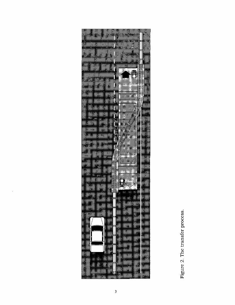
The movable concrete barrier (MCB) system (see Figure 1) consists of seg- ments 1 rn (39 in) long, 0.8 rn (32 in) high, and 0.6 rn (24 in) wide at the base. Each segment weighs approximately 635 kg (1400 lb) and is connected by two hinges attached to each end of the segment. The barrier is moved with a trans-

Figure 1. A section of the movable concrete barrier with a hinge.
port/transfer vehicle (TTV) that lifts the segments off of the pavement and later- ally repositions them at distances from 1.2 to 5.5 rn (4 to 18 ft) at speeds of about 8 kph (5 mph) (see Figure 2). The MCB system is manufactured by Bar- rier Systems, Inc. (BSI) and is called the Quick Change MCB System.
Construction on 1-66
A travel lane was constructed on the right shoulder of a section of 1-66 in Fairfax County. This new lane is made of portland cement concrete and is about 9.6 km (6.0 mi) long. New asphalt shoulders were constructed, and guardrail was installed.
When the construction was completed, the inside lanes were to become high occupancy vehicle (HOV) lanes during the peak periods, and the shoulder
was to become a travel lane. Two provisions were added to the contract because of concerns about safety and capacity: (1) all work was to be performed behind concrete barriers and (2) lane closures would only be permitted for 4 hr during the day and 8 hr at night. Consequently, a MCB system was the only practical way to satisfy these provisions. The construction was done in two concurrent
projects: (1) 1-66 from the Route 50 interchange to the Vienna Metrorail Station (4 lanes divided; 1991 ADT of 93,800) and (2) 1-66 from the Vienna Metrorail Station to 1-495, the Capital Beltway (6 lanes divided; 1991 ADT of 153,200). The construction work began in February 1991 and was completed in April 1993. Each project had an MCB system available for use. At the completion of the construction, the 2 MCB systems•which consisted of 2 TTVs, 3,963 rn (13,000 ft) of barrier from the first project, and 3,354 m (11,000 ft) of barrier from the second project•became VDOT property.
Project 1:1-66 From Rte. 50 to the Vienna Metro Station
During the preliminary stage, a 1.8-m (6-ft) asphalt shoulder was con- structed in the median in both directions for use as part of the inside travel lane. All travel lanes were shifted to the left 1.8 m to allow more room on the right shoulder for construction. Conventional barriers were used.
During construction of the new outside lane and shoulder, the MCB was
used for shoulder and right lane closures. Construction commenced on the west end of the project on the westbound side and proceeded to the eastbound side beginning on the east end.
Project 2" 1-66 From the Vienna Metro Station to 1-495
Project 2 differed from Project 1 in that (1) there was no widening of the median to shift traffic to the left because the Metrorail track occupies the median in this section of 1-66 and (2) construction began on the east end of the eastbound side and proceeded to the westbound side beginning on the west end.
For each project, the roadway was divided into two segments; that is, construction was performed on approximately one-half of one side of the road- way at a time.
OBJECTIVE AND SCOPE
The objective of this study was to evaluate the effectiveness of the MCB system and to develop guidelines for using it. The performance of the MCB sys- tem in setting and resetting the barriers and its performance in vehicle/barrier collisions were evaluated. Also, the costs associated with the use of the MCB system were examined, and the system's advantages and disadvantages were assessed.

METHODS
Four activities were conducted to accomplish the study objectives:
1. Literature review. Literature on the MCB system, including reports on its use in Washington, D.C., North Carolina, Montreal, and Connecticut was reviewed.
2. Data collection. A data collection plan that focused on data collected by the VDOT inspectors assigned to the two construction projects was developed and implemented. This plan included a monthly report form on the activities of the MCB systems that was completed by the construction inspectors and mailed to the Research Council. Research Council staff made periodic visits to the con-
struction sites to observe these activities.
3. Evaluation of the MCB. The collected data on the performance of the MCB system with respect to laterally repositioning the barrier, reports on vehi- cle/barrier collisions, and costs were analyzed to assess the performance of the MCB.
4. Development of guidelines for using the MCB. Based on the experiences on these two projects, the literature review, and possible applications of the MCB, guidelines for the use of the two MCB systems were developed.
RESULTS AND DISCUSSION
Performance of the MCB System
The performance of the MCB system is discussed in four sections" (1) the barrier, (2) the TTV, (3) the MCB system in general, and (4) protection of the bar- rier end. The description of the performance was based on information obtained from the monthly reports submitted by the project inspectors, field visits by Research Council staff, and telephone conversations with the project inspec- tors. A summary of the monthly reports is included in the Appendix.
The Movable Concrete Barrier
Shipments of the MCB began arriving at the construction site in May 1991, and by June the barriers were in place. During the initial months of oper- ation, it was noted that during the transfer process, the bottom corners of adja- cent barriers were making contact causing the corners to crack and break (see Figure :3). According to BSI, this chipping of barrier corners is viewed as a wear-

Figure 3. Photo of a MCB with chipped corner.
ing in or seasoning of the MCB; it has occurred on all projects using MCB. 1 The chipping was superficial and did not affect the structural character of the MCB. The likelihood of chipping is increased when transfers are made at an excessive speed. On both projects, about :30 to 40 percent of the MCBs had chipped cor-
ners after about 6 weeks of use. The contractors agreed to reduce the speed of the barrier transfer. The chipping ceased after about :3 months.
Two types of delineators were mounted on the MCB. A side-mounted standard plastic delineator was spaced ever• 12 3 m (40 ft) at a maximum height of 0.6 rn (25 in). Also, two 104.04 cm
(1• in 2) yellow reflective sheeting panels were mounted side by side on top of the MCB at 24.6 m (80 ft) intervals
as shown in Figure 4. The panels were fastened to the MCB with a rubber attachment that allowed the panels to bend backwards as the barrier was
moved by the TTV. The delineators performed well; they didn't fall off the MCB
nor hinder the TTV's operation.
There was some discussion on the use of a skid pad assembly on the bot- tom of the MCB. The skid pad was designed to prevent the creeping that has occurred at some project sites. VDOT staff did not think there was a need for the skid pad. Although the skid pad was not used, no skidding occurred.
Transport/Transfer Vehicle
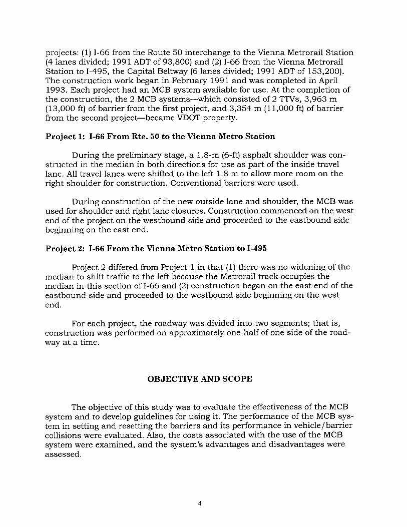
During the transfer process, the conveyor system of the TTV Model 3 (TTV-3) is the component that lifts and repositions the barrier as the transfer

Figure 4. Yellow reflective-sheeting panels mounted on the MCB.
vehicle moves along the highway. The TTV-3 and conveyor system are shown in Figures 5 and 6, respectively. Although the TTV-3 is also capable of picking up as many as 15 barriers at one time and transporting them to another site, this feature was not used on the 1-66 projects. The TTV-3 is powered by a 6 cylinder turbocharged John Deere diesel engine and has two operatin•g ranges, low, up to 11.2 kph (7 mph) and high, 12.9 to 32.2 kph (8 to 20 mph).•The typical TTV-3 is 14.2 m (46.5 ft) long and 3.4 to 4.1 rn (11 to 13.5 ft) wide with a 9.3 m (30.5 ft) wheel base and weight of 14,515 kg (32,000 lbs). 2 Two operators, one guiding each end of the TTV-3, were used to make the MCB transfer (lane closing/open- ing). Using an intercom system with headsets, the operators talked to each other to coordinate and facilitate TTV-3 operations.
The TTV-3's s-shaped conveyor system has five parts" infeed and outfeed sections, curved infeed and outfeed transfer sections, and the middle transfer pivot (Figure 7). As the TTV-3 moves forward to make a transfer, the infeed sec-
tion connects with the MCB and lifts it off the road. The curved infeed transfer section moves the MCB to the middle transfer pivot, which diagonally moves the MCB to the curved outfeed transfer section. The outfeed transfer section realigns the MCB to its final position where it is lowered to the road and released by the outfeed section. 2
The wheels (or rollers) of the conveyor system make contact with the bot- tom of the T-shaped barrier top to perform the barrier transfer. These wheels, which are made of urethane, were designed to wear rather than cause wear on
the barrier. Consequently, some maintenance is required to replace the wheels.
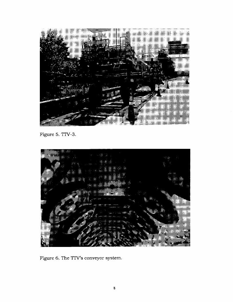
Figure 5. TTV-3.
Figure 6. The TTV's conveyor system.

•3Z• •<•-
0
•D
0
0

It is roughly estimated that (1) wheels in the curved infeed and outfeed transfer section should be replaced every 20 hr of operation and (2) wheels in the straight sections•the infeed, middle transfer pivot, and outfeed sections• should be replaced every 40 to 60 hr. 2 These estimates were cited by a BSI offi- cial. This would amount to wheel replacement at a minimum of about every 2 months. According to a VDOT inspector, wheel replacement was more frequent at the beginning of the project. This is probably because there was more wear and tear on the wheels when the operators were inexperienced with the TTV-3 and transfer operations. Also, the wheels were checked daily for tightness because loose wheels can damage the barrier.
On the first project, the TTV-3's main power fuse blew 6 times during the first 9 months. BSI recommended a larger fuse. However, the larger fuse blew 2 more times. By correcting a short in the electrical system, BSI resolved this problem.
The hydraulic pump on the TTV-3 failed after about 14 months on the first project. The opening of a closed lane was delayed about 2 or 3 hr so that the hydraulic pump could be replaced.
MCB System Usage
In order to unload the MCBs from the flatbed trailer that transported them to the construction site, the two contractors fabricated a lifting device to lift the barrier using a gradeall and a loader or cherrypicker. Such a tool was not provided by BSI, and it took about a week to make. On the first project, the device was designed to lift two MCBs at once, whereas the device for the second project liked three MCBs at once. The device lifting two MCB sections is pre- ferred because when three MCB sections were lifted the outside sections were bowed, indicating that the sections were under stress and too much weight was being lifted.
During the monitoring period, there were 110 lane closures on the first project and 71 on the second project (see Table 1). On both projects, there were
an average of 12 lane closures per month. If it is assumed that this monthly average also applied for the months that the MCB was used but not monitored (June through August for Project 1 and June through September for Project 2), then the estimated total number of lane closures was 146 for Project 1 and 119 for Project 2. The inspectors and the contractors were very pleased with the operation of the MCB system.
Advantages
1. The work zone is protected by a physical barrier that is easy to move. The conventional concrete barrier and plastic drums, which are the current alternatives, cannot provide both of these features.
10

Project
Table 1 MCB LANE CLOSURES
Number of Lane Closures
Day Night Total
1 Total 63 47 110 Monthly Average 7 5 12
2 Total 53 18 71 Monthly Average 9 3 12
1 & 2 Total 116 65 181 Monthly Average 16 8 24
The data are for a 9-month period for Project 1 and a 6-month period for Project
2. By closing a lane, the MCB system allowed easy access to the work area from a road surface. The use of a conventional concrete barrier for a shoul- der closure would have made it necessary to access the system from the ground at the roadside. Working in the mud would have resulted in delays because of the difficulty in moving equipment and workers. Easy access also made the job of inspecting less time consuming and more thorough. 3
3. The MCB system allowed fast lane closures and openings. The MCB took 30 min to open and close a lane, whereas plastic drums would have taken about 2.5 hr. This provides an additional 2 hr each day for construction instead of setup time. This increased productivity by about 30 percent during the slip forming of the concrete. 3
4. By limiting lane closures to nonpeak periods, the MCB helped to main- tain capacity and minimize the impact of the construction work on motorists.
5. The contractors and VDOT's inspectors agree that the MCB system was
a positive factor in the timely completion of both projects. Unfortunately, it is diffi- cult to assess the impact of the MCB system on the timely completion of the project because additional work was specified. On Project 1, although the removal of naturally occurring asbestos and the construction of a drop-off lane at an interchange was added to the contractor's workload, the project was com- pleted 5 months ahead of schedule.
Disadvantages/Needs
1. The recommended speed of the TTV-3 during the transferprocess should be emphasized at the beginning and throughout the project to minimize the chip- ping of the barriers.
11

2. A kink (MCB section out of alignment), which was most likely caused by a vehicle sideswiping the barrier, was occasionally observed. When a kink was removed or realigned during the transfer process, the transfer time was increased. A method for effectively removing a kink in the MCB with little loss of time would be helpful.
3. One of the biggest challenges was identifying a cost-effective way of pro- tecting the end of the MCB.
Protecting the end of the MCB
The initial plans for both projects specified a Type 1 attenuator, which must be bolted to the pavement to protect the barrier end (see Figure 8). The Type 1 attenuator is routinely used for concrete barriers. Plans were made to substitute a Type 2-1 1 attenuator, which is a portable pallet-mounted impact attenuator including sand barrels (see Figure 9). It was estimated that it would take 1 hr to move the Type 2-1 1 attenuator from the shoulder to the roadway for a lane closure and vice versa. Consequently, to close and open a lane would take 2 hr. The use of a truck-mounted crash cushion (TMCC) (see Figure 10) was estimated to take 4 min to reposition to open and close a lane. Therefore, the easy-to-move TMCC was selected to protect the blunt end of the barrier, and it was positioned about 3.1 m (10 ft) in advance of the MCB.
Figure 8. Type 1 attenuator: Guardrail Energy Absorbing Terminal.
12

Figure 9. Type 2-1 1 attenuator: sand barrels.
Figure 10. Photo of the TMCC.
13

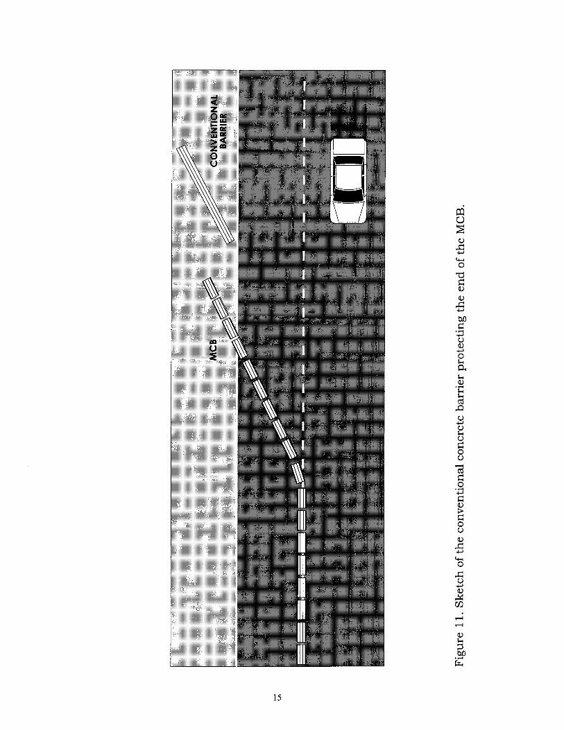
During one phase of Project 1, a conventional concrete barrier taper was used to protect the MCB. The conventional barrier end was protected by a Guardrail Energy Absorbing Terminal (GREAT) attenuator (see Figure 8). The first sections of the MCB were also in a taper when positioned on the shoulder and when transferred for a lane closure (see Figure 1 1). Although this arrange- ment provided adequate protection of the end of the MCB, it was harder for the TTV-3 to pick up the MCB in the taper; thus, the TTV-3 speed was reduced dur- ing the transfer. The TTV-3 operators have to maneuver the TTV-3 at an angle to
move the MCB taper. This puts additional stress on the TTV-3 and conveyor rollers. The contractor's project manager thought that this was a better method of protecting the end of the barrier despite the difficulty in moving the MCB taper. Consequently, this arrangement may be worth trying on a future project. Another portable crash cushion that may be worth trying in the future is under development under the Strategic Highway Research Program's (SHRP) Work Zone Safety Devices program. A tilt bed with rows of rollers allow the sand bar- rels to be easily unloaded and loaded on the tilt bed with assistance from an
electric winch. 4
The Virginia Work Area Protection Manual requires that a conventional lane closure taper be used in advance of the barrier lane closure. 5 It would gen- erally take 30 to 45 minutes (depending on traffic volume) to set up or remove a
taper of plastic drums and signs for the lane closure.
Costs Associated with the MCB
Initial Cost
The initial cost of the MCB system was $1.5 million for Project 1 and $1.09 million for Project 2 (see Table 2). The primary reason for the cost differ- ence is that Project 1 required 570 m (2000 ft) more barrier than Project 2. Also, the bids by the two contractors for the MCB systems were different. The cost of the TTV-3 was $29,000 higher for Project 2 than Project 1. On the other hand, the cost per meter for the MCB was approximately $70 higher for Project 1 than Project 2.
Table 2 INITIAL COST OF THE MCB SYSTEM
Project TTV Cost MCB Total Cost MCB Cost/m Total
1 $246,000 $1,240,000 $312 $1.50 million
2 275,000 816,750 241 1.09 million
14

VDOT considered the option of leasing each MCB system for about $800,000 to $900,000. By purchasing the systems, VDOT has the two systems for many future uses for an additional $200,000.
In-Place Costs
In the special provision for MCB service, it was stated that the MCB ser- vice will be measured and paid for in units, of linear feet per location. There were 6 work zones for Project 1 employing 26,020 m (84,560 ft) of MCBs and 4 for Project 2 using 12,970 m (42,150 ft) of MCBs. The total cost of setting up the MCB system several times for each project were $341,400 for Project 1 and $183,400 for Project 2 (see Table 3). The cost per meter for Projects 1 and 2 were $13 and $14, respectively. There was no additional charge for opening and closing a lane using the MCB system.
Table 3 IN-PLACE COSTS
Project Meters of MCB Cost/m Total Cost
1 26,020 $13 $341,400
2 12,970 14 183,400
A substantial additional cost for the MCB system was the cost of the TMCC. The special provision for TMCC specified a per-hour pay unit, and the charge per TMCC for both projects was $10 per hr. Obviously, the special provi- sion's pay unit was established for short-term use of the TMCC. On the average, two TMCCs were used on each project for as long as the MCB was on the road. In other words, two TMCCs were used continuously during the project. For Project 1, the estimated cost for TMCCs was $260,000 for 15 months, and for Project 2, the estimated cost was $155,000 for 9 months. In the future, by using a fiat fee pay unit for the TMCC, a cost of about one-third to one-fifth of that charged for these projects could be expected.
The estimated total cost, initially and in-place, for the MCB system and including the TMCCs was $2.1 million for Project 1 and $1.42 million for Project 2. The total construction project cost was about $14.5 million for Project 1 and $12.5 million for Project 2. Thus, the MCB system and TMCCs accounted for 14.5 and 11.4 percent of the total cost for Projects 1 and 2, respectively. When the initial cost of the MCB system is omitted these percentages are 4 and 3 per- cent for Projects 1 and 2, respectively.
Review of Accidents Involving the MCB
Collisions with the MCB were reported on the monthly report form com- pleted by VDOT inspectors. Three collisions, all of which occurred on Project 1
16

with the MCB on the shoulder, are discussed below. Data from accident reports supplemented the monthly reports.
January 4, 1992
At about midnight on Saturday, January 4, 1992, a tractor trailer travel- ing east hit the TMCC in the gore area, ricocheted off, and "rode" the barrier. About 62 rn (200 ft) of barrier were pushed off of the pavement onto the O.62-m (2 ft) shoulder drop-off created by excavation. Although there were no major cracks in or structural damage to the MCB, there were some scrapes, chips, and paint marks. No barrier sections needed to be replaced. No injuries occurred; damage was estimated at $58,000.
April 9, 1992
At approximately 9"30 A.M., a tractor trailer traveling west on Thursday, April 9, 1992, had a swaying trailer that caused the driver to lose control, side- swipe a car, cross the median and eastbound lanes, and hit the MCB that was
on the right shoulder. The truck broke the barrier wall and came to rest on the right shoulder of the eastbound roadway on its right side with the front portion of the tractor on top of the MCB (see Figures 12 through 14). About 46 to 50 rn
(150 to 163 ft) of barrier were displaced. This is approximately equivalent to 45
Figure 12. Accident on April 9, 1992. The truck is on top of the MCB.
17

Figure 13. Truck and displaced MCB.
Figure 14. A damaged MCB section.
18

to 50 MCBs. Emergency operations required the removal of additional MCBs, bringing the total number of displaced barrier sections to 63. Four sections were severely damaged and were replaced, and a total of 67 barrier sections were
reset. It took about 5 hr to remove the truck from the scene and an additional 4 hr to reset the 67 barrier sections. The eastbound roadway was closed for about 30 minutes beginning at 10:00 A.M. to allow emergency vehicles to extricate the driver (who did not appear to have any life-threatening injuries) and for 1 hour beginning at 1:00 P.M. to remove the truck. The right lane was closed until 6:30 P.M. Damages were estimated at $54,400.
May 19, 1992
At approximately 3" 10 P.M. on Thursday, May 19, 1992, a pick-up truck traveling east collided with the barrier on the right shoulder after the driver slowed down because of traffic and lost control. Nine sections of barrier on the eastbound shoulder were moved about 0.6 to 0.9 m (2 to 3 ft). There was no
damage to the barrier; the driver was not injured; there was $1,800 worth of damage to the vehicle.
Miscellaneous Hits
The inspectors noted that typically about three or four barrier sections were pushed laterally about three times each month. This displacement was probably caused by vehicles that failed to stop after sideswiping the MCB or the reported accidents that are discussed in the next section. The inspectors also observed that the MCB appears to be slightly more forgiving than the conven- tional concrete barrier because the shorter, lighter MCB sections are more likely to move laterally when hit than the conventional barrier. When an MCB section is hit by a vehicle, adjacent sections also are displaced, thereby dissipating some of the impact while still redirecting the vehicle. When a conventional bar- rier section is hit by a vehicle, this heavier barrier (almost four times heavier) is less likely to move.
Reported accidents
Data on collisions with MCB reported by police and occurring between May 1991 and August 1992 were obtained from VDOT's Traffic Engineering Division. A limited amount of conventional concrete barrier was used during the construction, but the location of the conventional barrier was not fully known. Therefore, some of the reported accidents may have involved conventional bar- rier and not the MCB. There were 42 accidents involving the barrier during both projects. Accident data by project, direction of travel, accident severity and type, and light and pavement conditions are shown in Table 4. None of the accidents were fatal, and 33% resulted in injuries. In 38% of the accidents, a single vehi- cle was involved, and in 62% of the accidents, the first event was a collision with
19

Table 4 ACCIDENT DATA SUMMARY
(A) Summary of accidents by type and number of vehicles
Accident Type No. of Vehicles
Injury PDO Total 1 2 3+
Route 50 to Metrorail EB 1 10 11 2 6 3 WB 3 8 11 7 4 0
Total: 4 18 22 9 10 3
Metrorail to 1-495 EB WB
5 4 9 4 4 1 5 6 11 3 6 2
Total Of Both Projects 14 28 42 16 20 6
(B) Summary of accidents by type of collision, light conditions, and road conditions
Type of Collision (First Event)
Hit Barrier
Side- swipe
Rear- end
Angle
Route 50 to Metrorail EB WB
Total:
Metrorail to 1-495 EB WB
Total:
Total of Both Projects:
5 9
14
5 7
12
26
Other
Light & Road Conditions
Dark Light
5 6 4 7 9 13
3 6 5 6 8 12
17 25
Wet Road
10
the barrier. The light conditions were dark during 40% of the accidents, and the pavement was wet when 24% of them occurred.
If 3 collisions occurred each month as estimated by the inspectors for Project 1, then the total for the 16-month period would have been 48. This esti- mate is slightly more than double the 22 accidents reported for Project 1. As many as 50% of the collisions with the MCB may go unreported.
Given the proliferation of collisions, the inspectors and contractors stressed the importance of having a concrete barrier to protect the work area, especially on roadways with a high volume of traffic traveling at high speed. There was one incident in which a vehicle entered the work zone; that was the truck collision on April 9, 1992. There were no reported accidents that occurred
2o

during a lane closure or during the transfer process. The MCB system per- formed very well in redirecting the errant vehicles that collided with it and in providing protection for the workers in the work zone.
Quality of the Data
The project inspectors were the primary source of information for the study because the inspectors were familiar with the daily construction activities during the project. The disadvantage of this approach is that the research staff does not have control of the data collection and is dependent upon the inspec- tors for cooperation and the provision of reliable, complete data. On Project 1, the inspectors were interested in the research project, conscientious, and thor- ough in completing the monthly report. Although monthly reports were com- pleted for both projects in a timely manner, more detailed information was provided on Project 1. Fortunately, the inspectors on Project 1 were aware of many activities on Project 2 and were able to point out similarities and differ- ences in the two projects. It is the author's opinion that this awareness compen- sated for the lack of detailed information on Project 2.
MCB Use by Others
Oklahoma
The MCB was used on 1-240 in Oklahoma City on a bridge replacement project in which one of the two lanes on each side of the road was closed at times during the nighttime construction. 6 Sand barrels were used in an impact attenuator assembly to protect the end of the MCB. The need for a quicker, safer, and more cost-effective method to move the impact attenuator was noted as was the need for a supply of extra conveyor wheels for the TTV-3 to replace worn ones. A TMCC was not used because of its cost and its lack of side protec- tion. The TMCC was designed for collisions from the rear. Also, the truck on which the TMCC is attached could be hit.
Montreal
During major reconstruction of a six-lane, 5.6-km (3.5-mile) elevated sec- tion of A40 freeway with an ADT of 140,000 vpd, four lanes of traffic (two lanes in each direction during the day on weekdays) were required. 7 The MCB was moved twice daily on weekdays to close and open one lane in each direction for night work, and it was moved for weekend work. The 5.5-month reconstruction (April through October 1990) included replacing expansion joints, pavement reconstruction, and replacing a median barrier. Construction proceeded as fol- lows" (1) the median barrier was removed, and the median and the inside lanes in each direction were closed for reconstruction, repaving, and the rebuilding of
21

the median barrier and (2) traffic was shifted to the rebuilt section (two lanes in each direction) and the two outside lanes in both directions were reconstructed. An MCB system was used on each side of the roadway to open and close lanes. The project was completed on time despite about a 30 percent increase in the workload from additional construction activities.
Washington, D. C.
The MCB system was used for the reconstruction of 1.6 km (1 mi) of a six- lane, elevated section of 1-395 that has an ADT of more than 158,000 vpd. 8 Five lanes of traffic were maintained (three lanes in the peak direction) while major deck repairs, resurfacing and substructure reconstruction, and median barrier replacement took place. Two 1.6-km (1-mi) sections of MCB were used: one sec- tion to protect the work zone and the other section to serve as a median barrier separating opposing traffic. The 13-month project (April 1990 through May 1991), during which the MCB was moved twice daily, was completed 81 days ahead of schedule. The project was performed in four phases: (1) the median barrier was removed, and the median was repaved to serve as travel lanes; (2) one side of the road was closed for construction, and traffic was moved to the median and the other side of the road; (3) once the new construction was com- pleted, the other side of the road was closed, and traffic was shifted to the reconstructed side and the median; and (4) the median barrier was rebuilt. VDOT's Northern Virginia District personnel observed the operation of the MCB system on this project; subsequently, VDOT decided to use the MCB system.
Connecticut
The reconstruction of the Morano Bridge on the Connecticut Turnpike required that five lanes of traffic (three lanes in the peak direction) be available on a 3.17-km (1.96-mi) section. 9 Several problems were experienced on this project. First, because the traffic volumes during the peak periods were about equal in both directions, the motorists traveling in the direction with two travel lanes experienced congestion during the peak periods each weekday during the 2-year construction. Apparently, the actual traffic volumes were not used to plan the work zone traffic control. Secondly, the MCB tended to creep or move
slightly from its original position. It was believed that reverse vertical curves and a grade of more than 3 percent were the prime causes of the creep. The creep created compression zones in the MCB chain, which were corrected by using the TTV to relocate barriers, and this was a difficult operation. This relocation and the use of the TTV to realign barrier sections that were deflected after a
vehicular collision imposed stresses on the TTV that likely resulted in cracks in the TTV frame. The need for an alternate method to straighten dislocated MCBs was noted.

North Carolina
The North Carolina Department of Transportation has employed the MCB 10 system on pavement rehabilitation projects on 1-77, 1-85, and 1-95. It •s
expected that the 1-95 project underway will be the first project that will have regular and frequent MCB transfers. Data on vehicular collisions with the MCB indicate that it performed satisfactorily. North Carolina Department of Trans- portation officials expressed some concern regarding the need for a buffer area when the MCB is deployed as a median barrier. Two incidents of MCB displace- ment resulted in a deflection of 0.6 m (2 ft) or less. A 1.5-m (5-ft) buffer was specified for the 1-95 project, during which the MCB will be used as median bar- rier for two-lane, two-way operation.
Guidelines for Using the TMCC
The major benefit of the MCB system for construction projects is its abil- ity to open and close a lane quickly while providing physical protection to the work area. Consequently, any guidelines for its use should focus on this benefit. Construction projects on high volume, congested roadways, especially urban freeways or expressways, are the likely candidates for use of the MCB system. On most congested freeways, it is not possible to close a lane during the peak periods without adversely affecting the traffic flow. Therefore, lane closures are limited to the off-peak periods during the day and at night. During this project, the MCB system provided good access to the construction site. Use of the MCB system to provide a quick median barrier shift was successfully demonstrated in Montreal and Washington, D.C. The guidelines could become an impediment to the use of the MCB system if they are too restrictive. Moreover, it is the opin- ion of the author, VDOT inspectors, and BSI officials that simple, general guide- lines would be easier to use than specific guidelines regarding traffic volume, road type, speed, type of construction, number of lanes, etc. Because each con- struction project is different, general guidelines rather than specific ones are
more appropriate and allow greater flexibility. An official of BSI stated that most states use the MCB system in areas where they have no choice. 11
The use of the MCB system is suggested where it is the only practical method for providing (1) barrier protection and a quick lane closure and opening and (2) a quick median barrier shift. The MCB system is recommended for use by VDOT on the planned construction projects to widen 1-66 from Route 50 to Route 234, the portion of 1-66 just west of the construction sections described in this report.
Another use of the MCB system is on construction projects on roadways where traffic volumes permit 24-hr lane closures and the construction requires multiple closures of one lane for a short period, for example, a lane closure for 2 to 7 days in phases or sections along the length of the project.

If VDOT requires that the MCB system be used on a construction project, then a statement in the contract should specify that VDOT will provide the MCB system and that the contractor will be responsible for the system from the time the system is obtained from VDOT until it is returned to VDOT. If VDOT decides that deployment of the MCB system is an option for a particular project, then a general note stating the availability of the system and the requirements for its use should be included in the contract requirements.
To protect VDOT's investment in the MCB system and to ensure its proper use, a 30-hr training program from BSI should be required for the con- tractor's personnel who will operate and maintain it. A statement regarding this requirement should also be included in the contract.
The TMCC appears to be the most efficient way to protect the end of the MCB when frequent lane closures are required. The contract requirements should specify that a fiat fee should be paid for the TMCC rather than an hourly rate. Substantial savings are expected if a fiat fee is used instead of the hourly rate used on the 1-66 projects. Other approaches to protecting the end of the MCB should also be considered by VDOT.
CONCLUSIONS
1. The MCB system performed adequately for the transfer operations. Only one instance of a delay in transfer operations as a result of equipment mal- function was documented.
2. The costs of the MCB systems for the two projects were similar. If the cost of buying rather than leasing an MCB system is compared, the decision to buy is justified.
3. It is estimated that a 30 percent increase in productivity was realized by using the MCB rather than plastic drums to separate the traffic from the work area during lane closures.
4. The MCB performed very well in safely redirecting errant vehicles and protecting the work area from vehicular intrusion. There was one incident in which a tractor trailer broke through the MCB.
5. A TMCC was used in lieu of sand barrels to protect the blunt end of the MCB because of its ability to be moved quickly in conjunction with barrier transfers. On the other hand, the cost of the TMCC was exorbitant because it was based on the conventional hourly pay unit for short-term operations instead of a fiat fee for long-term use.
24

6. General guidelines were developed instead of specific guidelines because of the unique nature of each construction project.
RECOMMENDATIONS
1. The Northern Virginia District should use the following guidelines for deciding when to use the MCB system for a construction project" The MCB sys- tem should be used on high volume, congested freeways (1) when a lane closure is necessary but it is not possible to close a lane except during limited hours of the day (that is, off-peak daytime hours and at night) and (2) when the MCB would serve as a median barrier as a result of the median being needed as a travel lane in order to maintain all lanes in the peak direction during the peak period. In short, the MCB system should be used when it is the only practical method for providing barrier protection and a lane closure/opening or median barrier shift quickly. The MCB system could also be used on projects on road- ways on which traffic volumes permit a 24-hr lane closure and the construction requires multiple closures of one lane for a short period. An example of this application would be a lane closure for 2 to 7 days in sections along the length of the project.
2. The MCB system is recommended for use on the widening of 1-66 from Route 50 to Route 234, which is the portion of 1-66 just west of the section where the construction described above occurred.
3. Any construction contract that involves the use of the MCB system should include" (1) a general note stating whether the use of the MCB system is mandatory or is an option and requirements for its use, (2) a note stating that the contractor's personnel who are responsible for operating and maintaining the MCB system will attend a 30-hr training program on the MCB system from BSI, and (3) a note stating that the pay unit for the TMCC (when it is used) will be a fiat fee. The MCB service should continue to be measured and paid in lin- ear meters (feet) per location.
4. Although the TMCC is the most efficient way to protect the barrier end, VDOT should also consider other approaches such as tucking the MCB behind conventional concrete barriers or using a tiltbed trailer with sand barrels.
5. VDOT, with assistance from BSI, should pursue alternative methods of removing kinks in the MCB.
25

ACKNOWLEDGEMENTS
Special thanks are extended to Steve Gracey and Cher Kennedy, the Fair- fax Residency inspectors on Project 1. They have provided substantial input on the monitoring and performance of the MCB system and suggestions for improving it. The contributions of the following are appreciated" Larry Pope of the Fairfax Residency for providing information on Project 2; Dave Kovarik of the Northern Virginia District for providing background information; Earl Stitzer and staff of the Traffic Engineering Division for providing accident data; Jan Kennedy and Steve Blackwell for data analysis; Eileen F. Dieck and Linda Bar- sel for preparing the final report; Randy Combs for report graphics; Roger Howe for editing the report; and Mike Perfater, Gary Allen, Steve Gracey, Gerald Fisher, Dave Kovarik, and Cheryl Lynn for reviewing the final report. This study was supported by HPR funds administered through the FHWA.

REFERENCES
1. Korfin, A. I., Barrier Systems, Inc. Letter to M. Salehi, Virginia Department of Transportation, September 23, 1991.
2. Oliver, M. B. 1990. Overview of a movable concrete barrier system. Wash- ington, D. C." Federal Highway Administration.
3. Kennedy, C. G. Virginia Department of Transportation. Letter to A. I. Kor- fin. Barrier Systems, Inc., September 8, 1992.
4. Strategic Highway Research Program. 1992. SHRP Project Catalog. Wash- ington, D.C.
5. Traffic Engineering Division, 1993. Work Area Protection Manual. Rich- mond" Virginia Department of Transportation.
6. Kennedy, P. A. 1988. The use of movable concrete barriers for traffic control in work zones. Oklahoma County: Oklahoma Department of Transporta- tion.
7. Barrier Systems, Inc. 1990. Case Study: Reconstruction of a congested six- lane elevated highway QMBC application on the A40 in Montreal, Canada, April October 1990. Sausalito.
8. Barrier Systems, Inc. 1991. Case Study: Rehabilitation of an elevated six- lane freeway while maintaining peak directional traffic- QMBC application on SE/SW (I-395) Expressway Washington, D. C., April 1990 May 1991. Sausalito.
9. Rolfe, M. D. 1991. Performance evaluation of the movable concrete barrier system. Hartford" Connecticut Department of Transportation.
10. Stanley, M. T. 1993. Interim report No. 2: In-service performance of the Quickchange movable concrete barrier system. Raleigh: North Carolina Department of Transportation.
11. Ciccotti, J. L. Barrier Systems, Inc. Conversation with the author, February 9, 1993.
27

Appendix
Summary of the Data Included in Monthly Reports

1-66 From Route 50 to Metro Station
TIMES BARRIER USED
Month/Year
9/91 10/91 11/91 12/91 1/92 2/92 3/92 4/92 5/92 6/92 7/92 8/92
Total
Day
9 12 10 10 0 0 9 3 3 0 0 7
63
Night
9 9 8 2 0 0 0 1 0 0
18 0
47
MAJOR CONSTRUCTION ACTIVITY CHANGE
Change Date
9/12, 13, & 14/91
9/16, 17, & 19/91
I0/2 & 3/91
10/3, 4, & 5/91
Activity Change
3,567 ft of barrier moved from C503s WB side to EB side
1,336 ft of barrier moved from C502s WB side to EB side
3,624 ft of barrier relocated along C502s EBL
3,824 ft of barrier relocated along C502s EBL
11/6 &7/91
11/8/91
Ii/20 & 25/91
12/91
1/92 & 2/92
3/92
4/92
5/92
3,093 ft of barrier relocated eastward on C502s EBL
686 ft of barrier relocated eastward on C502s EBL
2,555 ft of barrier relocated eastward on C502s EBL
None
Lane construction shutdown operations on 12/20/91 & did not
resume operations until early or mid March 1992
None
600 ft of barrier moved from mainline and stockpiled because no longer needed at location
None
31

Month/ Year
9/91
9/91
9/91
9/91
10/91
10/91
10/91
10/91
11/91
11/91
11/91
12/91
12/91
1/92
2/92
3/92
3/92
4/92
4/92
5/92
5/92
6/92
7/92
7/92
8/92
8/92
ADDITIONAL COSTS FOR BARRIER AND TRAFFIC CONTROL
Activity or Item Description
Transfer of TTV-3 from one side of 1-66 to other side
Transfer of TMCC from one side of 1-66 to other side
TTV-3 used for lane closure
TMCC used for lane closure
Transfer of TTV-3 from one side of 1-66 to the other
Transfer of TMCC from one side of 1-66 to the other
TTV-3 used for lane closure
TMCC used for lane closure
Eastward transfers of TMCC 5 times
TTV-3 used for lane closure
TMCC used for lane closure
TTV-3 used for lane closure
TMCC used for lane closure
None
None
TTV-3 used for lane closure
TMCC used for lane closure
TTV-3 used for lane closure
TMCC used for lane closure
TTV-3 used for lane closure
TMCC used for lane closure
None
TTV-3 used for lane closure
TMCC used for lane closure
TTV-3 used for lane closure
TMCC used for lane closure
Item Cost (Dollars)
100
25
50
10/hr
100
25
50
10/hr
25
50
10/hr
50
10/hr
50
10/hr
50
10/hr
50
10/hr
Total Cost (Dollars)
900
150
900
500
125
1050
125
900
600
450
50
200
10/hr
50
lO/hr
150
900
350
32

Date
9/91
10/25/91
10/91
11128191
12/91
1/92
2/92
3/92
4/92
5/92
6/92
7/92
8/7/92
PROBLEMS WITH TRANSFER VEHICLE OR BARRIER SECTIONS
Description of Problem
Barrier sections" Adjoining bottom corners collide and become bro- ken as they articulate through the TTV-3. A design problem having no apparent influence on the sys- tem's usefulness, efficiency, and durability.
Breakdown of TTV-3 caused by blown fuse
Wearing out of rubber transport rollers
TTV-3's engine would not start
Replacement of lateral transfer rubber rollers due to normal wear and tear
None
None
Barrier machine's main power source fuse has blown 5 or 6 times since start of use of machine
None
None
None
None
Hydraulic pump failure
Action Taken
None
Fuse replaced
Replacement
Repairs by Con- tractor's mechan- ics
Replacement
None
None
Barrier system's representative recommended using a bigger fuse. Fuse still has blown a cou- ple times
None
None
None
None
Impact of Problem (Hr or days of delay)
None
Little, if any
None
l-hr delay of activity due to no lane clo- sure
None•normal oper- ating expense
None
None
None
None
None
None
Replaced hydrau- lic pump
None
Unable to reopen the closed lane as sched- uled. Delayed ap- proximately 2 or 3 hr.
33
Date a Time
(Evidence Noticed)
9/91
10/91
11/91
12/91
1/4/92
2/92
3/92
None
None
None
None
24:00
None
None
9:30 4/9/92
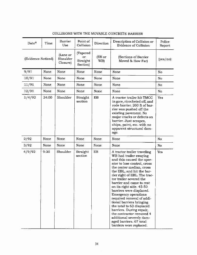
COLLISIONS WITH THE MOVABLE CONCRETE BARRIER
Barrier Use
(Lane or Shoulder Closure)
None
None
None
None
Shoulder
None
None
Point of Collision
(Tapered or
Straight Section)
None
None
None
None
Straight section
None
None
Straight section
Shoulder
Direction
{EB or WB)
None
None
None
None
Description of Collision or Evidence of Collision
(Sections of Barrier Moved & How Far)
None
None
None
None
Police Report
(yes/no)
No
No
No
No
EB
None
None
EB
A tractor trailer hit TMCC in gore, ricocheted off, and rode barrier. 200 ft of bar- tier was pushed off the existing pavement. No major cracks or defects on barrier. Just scrapes, chips, paint, etc. with no
apparent structural dam- age.
None
None
A tractor trailer traveling WB had trailer swaying and this caused the oper- ator to lose control, cross the center median, cross the EBL, and hit the bar- rier right of EBL. The trac- tor trailer severed the barrier and came to rest on its right side. 45-50 barriers were displaced. Emergency operations required removal of addi- tional barriers bringing the total to 63 displaced barriers. During repair, the contractor removed 4 additional severely dam- aged barriers. 67 total barriers were replaced.
Yes
No
No
Yes
34

Date a
COLLISIONS WITH THE MOVABLE CONCRETE BARRIER (Cont.)
Time
(Evidence Noticed)
5/19/92
6/92
None
None
None
None
7/92
8/92
Barrier Use
(Lane or Shoulder Closure)
None
None
None
None
Point of Collision
(Tapered or
Straight Section)
None
None
None
None
Direction
(EB or WB)
None
None
None
None
Description of Collision or Evidence of Collision
None
None
None
None
(Sections of Barrier Moved & How Far)
Police Report
(yes/no)
No
No
No
No
aAbout 3 times each month, 3 or 4 barriers were pushed laterally on straight sections.
35

1-66 from Metro Station to 1-495
TIMES BARRIER USED
Month/Year
10191 11191 12191 1192 2192
Total
Day
11 7
15 17 3
53
Night
18
MAJOR CONSTRUCTION ACTIVITY CHANGE
Change Date
9/30/91
10131191& 1111191
12/91
1/92
2/7/92
Activity Change
Barrier moved from EBL 1-66 to WBL 1-66 about 400 ft.
Barrier moved from inside lane of WBL 1-66 to outside lane 1-66.
Balance of barrier, inside lane (east end of WBL) moved to outside lane (west end of WBL).
None
i ,913 ft removed from EBL.
35