Climbing the Limitless Mountain: Daoism and the Internal ...
Upload
trinhkhanhCategory
view
215download
0
C v I 1, i AND
-iktidcopy lllcr,, i,:-S. I
'z" " '" "' cTECHNICAL REPORT66-24-CM
- - Ll i
EXTENT AND CAUSE OF DETERIORATION
\• OF NYLON MOUNTAIN CLIMBING ROPE
Sby
Louis I. WeinerClothing and Organic Materials Division
U.S. Army Natick Laboratoriesand
Leo J. SheehanMaterials Laboratory
Boston Naval Shipyard
March .
Clothing and OrganicMaterials Division
T", 1 ,•
BestAvai~lable
Copy
DISTRIBUTION OF THIS DOCUMENT IS UNLIMITED.
The findings in this report are not to be construed as anofficial Department of the Army position unless so designatedby other authorized documents.
Citation of trade names in this report does not constitutean official indorsement or approval of the use of such items.
Destroy this report when no longer needed. Do not returnit to the originator.

Distribution of thisdocument is unl!imited AD
TECHNICAL REPORT66- 24-CM
EXTENT AND CAUSE OF DETERIATION OF NYLONMOUNTAIN CLIMBING ROPE
by
LOUIS I. WEINERClothing and Organic Material Division
U. S. Army Natick Laboratories
"and
LEO J. SHEEHANN, Materials Laboratory
Boston Naval Shipyard
March 1966
44 Project Reference: Seriest TS-1351C0024401A113
Clothing and Organic Materials DivisionU. S. ARMY NATICK LABCRATCRIES
Natick, Massachusetts 01760

I
FOREWORD
A study of the factors influencing the deterioration of nylonclimbing rope has long been overdue. The protection afforded by arope depends upon its ability to stop a fall adequately. While, ir±riany instances, proper belaying of the rope will reduce the impactthat must be sustained, there is still a substantial part of theenergy from a falling man that must be absorbed by the rope. Sincethe rope's energy-absorbing ability is a function of its strengthand elongation; any use factor that would influence these propertieswould also irfluence its protective potential.
The preliminary investigations reported here make it evidentthat appreciable deterioraticn takes place in nylon climbing ropethrough the mechanism of surface abrasion. Energy loss may be inexcess of 50 percent yet there may be only superficial evidence ofdamage. Accordingly, it is important to keep nylon climbing ropesunder constant close scrutiny and to remove from service any ropesthat show evidence of damage. As with other life-saving items usedby the military, such as parachutes and body armor, continuingsurveillance and control is essential to ensuire maximumi serviceabilityand protection at all times.
We wish to acknowledge the support received for this work fromthe Army Limited War Laboratory and particularly from Mr. Robert L.Woodbury of that agency for his insight into this problem and forhis interest and help with this project.
Most of the test results reported were obtained through thecooperation and under the direction of the late Mr. Leo J., Sheehanof the Materials Laboratory of the Boston Naval Shipyard. We wishto acknowledge his excellent cooperation, without which this studycould not have been conducted, and to extend our thanks to his staff.
S. J. KENNEDYDirectorClothing & Organic Materials Division
APPROVED:
DALE II. SIEL- ,
Scientific Director
W. W. VAUGHANBrigadier General, U.S.A.Commanding
ii
ini m muu lnn nmm n nu u • n n m n nun n m n nu n unwmn u mn •uu n nN um u l m lu n - in nn m .um n me an nnm m m lnu nm u m

I
C ONTENT1 -
?ame
L st of i'iures V
List of Tables v
Abstr, ct vi
I. Conclusions anit Reco•nmenoations 1
II. Background 3
III. Materials 3
IV. Test Procedures 5
A. ?hysical Properties 5
B. Mechanical Properti.es 51. Strength and Elongation 52. hnergy-absorbing Ability 63. Hardness 64. Stiffness (bending length) 65. Knotting Ability 76. Compressibility 8
C. Deteriorative Change 81. Fiber Abrasion 82. Changes Detected by Chemical, Microscopic,
and X-ray Study 9
D. Co'rrelation Analyses 9
V. Test Results 10
A. Physical Property Changes 101. Circumference 102. Linear Density 103. Yarns per Strand 12h. Yarn Ply 135. Yarn Twist 136. Yarn Distribution in Strand 13
B. Mechanical Property Changes 151. Strength and Elongation 152. Energy-Absorbing Ability 173. Hardness 204. Stiffness 205. Knotting Ability 216. Compressibility 21
iii

i
CONTENTS (cont'd)
C. Deteriorative Changes 231. Fiber Abrasion 232. Nylon Flui.dity and Ferric Chloride Solubility 243. Filament Structurrc Lain -e 264. Chn-ns . X-rIn D' I'li-;,ction Pattcrns 26
D. Correlation between Objective Data and Use
Histories 29
S. Correlation Between Objective Measures 33
VI. References 35
Appendixes
A. Individual Use Histories of Nylon MountainClimbing Ropes 37
B. Military Specification "Rope, Climbing, Nylon" 49
C. Rope Hardness Testing; Summirry of Observations 57
D. Computer Program for Coefficient of Correlation 67
E. Utilization of the Fisher "Z" Transformation forComparing the Significance of "r" Values 71
Iv

LIST OF FIGURES
No. Page
1. Cumulative Distribution of Selected Properties of18 Nylon Climbing Ropes 4
2. Apparatus Used in the Nylon Rope Hardness Test 7
3. Outer and Inner Portions of a Single Strand ofRope No. 2, Showing Inner Core Construction 25
L. Comparison of Abraded and Unabraded Areas ofRope Surface (magnification lOx) 27
5. Single Filaments Removed from Rope (magnification200x) 28
6. X-ray Diffraction Patterns of Fiber Bundles 29
7. Correlation of Use Index with Strength Loss
(11-rope series) 32
LIST OF TABLES
I. Three-Strand Rope Constructional Factors UI
II. Yarn Distribution in Strands 12
III. Strength and Elongation of Ropes 16
IV. Energy-Absorbing Ability of Ropes 19
V. Hardness, Stiffness, Knotting Ability, andCompressibility of Ropes 22
VI. Age, Use Index,and Fiber Abrasion of EighteenRopes 23
VII. Nylon Fluidity of "Bates" Ropes 24
VIII. Correlation Coefficients (above 0.50) BetweenUse Index and Objective Measures of Eighteen-Ropx Series 30
IX. Correlation Coefficients Between Use Index andObjective Measures of Eleven-Rope Series 31
X. Correlation Coefficients Between VariousObjective Measures of Eighteen-Rope Series 34
V

Abstract
An analysis was made of 20 nylon mountain climbing ropes whichhad been in use for periods up to 18 years, to discover the extentand cause of deterioration in strength and energy-absorbing abilityand changes in hardness and stiffness. Iz was found that loss instrength and energy-ablsorbing ability arise primarily from fiber-abrasion which occurs at the surface of the rope. The nature of therope construction is such that surface abrasion affects each of thethree strands of the rope and all of the yarns in each strand exceptthe few which constitute the so called "Inner-core." There isno evidence that sunlight damage occurred to any significant extentin these ropes. The amount of abrasion and loss of strength weredirectly related to the amount of use (not age), for those ropesthat had more quantitative use histories. A Use Index (computedfrom the number of days of use) may be used to estimate rope deteriora-tion. The extent of hardening and stiffening of the ropes was foundto vary over a wide spectrum, but the causal factors were not determined.
vi

EXTENT AND CAUSE OF DETERICHATION OF NYLON MOUNTAINCLIMBING ROPE
I. Conclusions And Recommendations
The overall purpose of this study was to examine a series ofnylon climbing ropes that had been used in the field and to deter-mine the character, extent, and cause of their deterioration.While not all of the answers to the deterioration problem werefound, considerable information was obtained, conclusions weredrawn, and recommendations were made for further studies and forspecific remedial action. It was concluded, in general, that:
1) A significant amount of deterioration occurs duringthe use of nylon mountain climbing ropes. This deterioration isdirectly related to the amount and type of use; it is not relatedto the age of the rope.
2) The deterioration due to use arises primarily fromfiber abrasion at the surface of the rope. This surface abrasion,by virtue of the rope construction, affects each of the threestrands and all of the yarns in each strand except the few whichconstitute the so-called "inner core".
3) Deterioration of climbing ropes is evidenced primarilyby losses in strength and energy-absorbing ability. The elongationof the ropes d6es not change to any great cxtcnt during use; thusthe loss in energy-absorbing ability is a direct result only ofthe loss in strength.
4) There is no evidence that ultraviolet radiation causessignificant deterioration of ropes following their exposure tosunlight.
5) A Use Index, based primarily on the number of days ofactual climbing use, correlates with the strength loss sustainedduring use and consequent2y may be used as a rough predictor of itsresidual service life. Obviously, the more reliable the use historythe more reliable will be the Use Index.
6) An important change that occurs in many nylon mountainclimbing ropes during use is a hardening and stiffening which,while not necessarily a form of deterioration, nevertheless has aprofound influence on their knot-holding ability and, consequently,on their serviceability. This study was not able to shed any lighton the probable cause of hardening. It may be related to aprocessing parameter such as heat setting but this has not beenproved unequivocally.
!

I
Detailed analysis of the data showed thatg
1) Distribution of the yarns in the "inner core" of eachstrand compared to the total yarns in the strand ranged from 10 to20 percent.
2) Strength loss of the ropes ranged from 9 to 62 percent,with an average of 39.2 percent. The major cause of strength losswas fiber breakage.
3) The hardness of the ropes ranged from 17 to 140 pounds,with an average of 52.2 pounds. Stiffness ranged from 3.7 t% 8.6"bending length" inches. with an average of 5.9 inches. Thecorrelations between hardness and stiffness and between hardnessand knotting ability were only moderate.
4) The Use Indexes. as computed by one rater, ranged from20 to 220, with an average of 141.6. The correlation coefficientsof strength. energys and abrasion measurements with Use Indexranged. for this rater, from 0°53 to 0.66 in an 18-rope series andfrom 0.67 to 0.77 in an 1l-.rope series that had more quantitativelyexact use histories.
5) The "Bates" ropes (two ropes that were subjected todetailed rheological and X-ray study) showed r.n evidence of ultra-violet or sunlight deterioration. Their nylon fluidity increc.sed0.1 and 0.? rhes respectively, but this is not considered indic-ative of photochemical deterioration. These ropes did showevidence of surface abrasion of fibers. which would explain theirlosses in strength and in energy-absorbing ability.
It is recovended that.
1, A system be dev 1sed for keeping a record of the daysthat each military nylon mountain climbing rope is used. Pendingfurther analysis and study, any rope with a total number of climbingdays in excess of 100 (from this study roughly equivalent to a 20%strength loss) should be withdrawn from service as a potentialclimbing hazard.
2) Selected samples from supplies of nylon climbing ropesin the field be sampled and analyzed with a view to determiningtheir level of deterioration.
3) A non-destructive test be developed for assaying theextent of fiber breakage due to surface abrasion.
4) Subjective evaluations of hardneez and stiffness bemade periodically. tLny ropes that vary markea-y fram the averageshould be withdrawn from service,
2
- -n -.u an ummu • m m n mun u ml nnmu uu • nn nw m n numu m n n mn n n u

A.i
$. ?z'Fthe7 re~searrh bE :.:ondu red to detern ne the c auseof the hardening of some -ropes with '::e and to devevaop maxiufactuyingand f".•iishing pro:edures that will miirlmize uhi, &tzange.
6) A roTa ..4tru~ture be daýelcned ir. which the ratio Lf1inirner co7-&' yarns t -he itota yezn: would be rai.;.ed so as to
reduce the number of yarr.s that woaAd be sub e2ted to surfaCeabrasior-. Any sucn cLanges mast be made wi-hotu infloencing thecritical strength and ýnergy-absoxbing pi.-per;.ies of the rope.
Rope Aas one of The fiis ii]dut -cral produc:ts to be aiade ofnylor. Nylon is ideal for tni-s app7li.:ation because of its hightenacity, low density: and nigh flexibility. The experience ofsportsmen and of military personnel prcvides amriple evidence of thesoundness of the desisior tr use' nylor- for m,:tar.Lain climbing ropes.However. as witt-h many high performance mteriala there has beer. atendency to expe'tA an infinite ser':i.oe !ife from nylon and to neglectto che(,Ak for subtle :-hangss in. its physiaI and ,..hemical propert.esthat (.ould influernc- is servi:eabili-ty and e , trhe safety of itsuse.
It has re.'ently beenr. brought to t a-1tentior.n of Army R&DpersonneX that acme nylon climbL-ag r'pe• beaone stiff and are cor-respondingly unable tc nold a knoT, thus fonri.)g a serious hazardto the ziimber (1). Also the relat.vely poor resistance of nylon*to ultraviolet (sunlight) radiation has bcein considered a wellestablished fa,-t and ,- a limiting faz-•or .x mary applications ofnylon (2). For these reasonm the U. o Army 1,tiek Laboratoriesconsidered it desirable to oonduz t a stuiy to dotezcmine the natureand amount of deterioration which o,:curs in nylon ropes as a resultof their contin-ied use. For such a study it was essential to obtainropes with a kno: i u-e history,
lIII Materia le
Eighteen nylon mountain ciimrlng ropes which had been in v,;efor as long as eighteen years we:.:, made available to the NatickLaboratories through the coope:ration cf Col. A. H. Jackman (3Wforrner-_; of the Off ice of The •iarte'aser General: and Mr. A. E.Petervson :4) of Washingto..-, D.C. Theeý, cpes had beer used bysixteen members of a mountain ciimbLng 2lub .nder varioc. Uliabingconditions. in various pazrts of the -'•utry, and for varioau periodsof time. The climbers gave: the ages of the ropes. a synopsis ofthe conditions under which each rope had been used since purchase;a descriptior of the storage conditions in terms of temperature,humidity, and presence of light; and aiso 3u-h gene:al conw-ents asthey wished (Appendix A). As might. be expec.t-d, some of theinformation about the ropes was q]u;-, _-,omprenensi-re and detailed
* cri 067. -, -W"

while some was rather sketchy and incomplete. Nevertheless, theseropes provided a pedigreed group and it was felt worthwhile toanalyze them comprehensively in the laboratory and to assess theirdegree of deterioration as a basis for possible future specificationaction.
In addition to the eighteen, two ropes (Special A & B) thathad been in use since 1946 were submitted by Mr. Robert H. Bates.These two ropes were subjected to special analyses involving nylonfluidity determinations and X-ray diffraction and photomicrographicstudy.
These twenty samples represented many types of rope that variedwidely in circumference and linear density. The yarn constructionranged from 1 to 7 ply, the yarns per strand from 7 to 19 (withboth "S" and "Z" twists in the strand yarns), and the colors froma light beige to a rather dark olive green. Although the greatvariety of the ropes prevented their performance characteristicsfrom being related to specific structural features, it did permitaverage levels and ranges of performance to be determined and thesewere useful in charactcrizing the rope population (see Fig. 1,representing cumulative distributions of four selected propertiesof 18 of the 20 ropes studied).
20;'--
.J BENDING CIRCUMFERENCE STRLNGTH . _
4 0 LENGTH (16'h in) LOSSeHARDNESS0 ie (Ib)
Z1-wD24
Z 4CL
ON VALEF 140 LBS
U.J
S~iS OFF THE GRAPHSo-• • I t ! I
,0 20 30 40 30 60 70 80MEASLJRED VALUE
Figu•re l, Cumulative distribution of s electedproperties of 18 nylon climbing ropes
4
--
Hi~ ~ ~ ~~ ~C Wm rn l m l ~ amImi i~li ia•Il I II lg I I / lllI •I m
IV !S du- -3
Tn: b~i~r casi ýa be divide-d in:.o three categrories-,Uncse used -,c evaiuate physizýa] prz~par~jlec and c cis truct.ion, thoseused -,o e-'7alate inecIhnsL-a.. proper-ties and -.hose used to evaluatefibý_: ab:.,&i end 7:mand or rniz;roscopi: changes.
A. PW~iLal Pr~rer 't:eas
TesýIc5- -,o de'terni~rne c4r~ufAenc.e, linear density, then~umbe,- of yae;-:~3 per .3!xandf the ply of the i7trarkd yarns. the twistof' the Ya.ns5- ard .ne .-irb&:' olf ýJbz yarns in t.he s'tiand were
2 arrlecl in 3.r .:.- -. a~: w- -0 `tha s .dard pro,-edu-a-- ,:ontaxired in
B,, Xea rarzic,;_?,P~ pertie--
1. '5,~gnai lnao Strength and elongatiormneasuremen,;s va.:e mad onaicrew- operxl d i4-nsi] e machi-ne of thecons tante-,-ceI-f-ext ensi on type. IThe-, t c±- ext~ension1 used was3 inshes. per p1:rnuT,-,, A iload-Cell weig~'ang system was used havingrange.z- of froni 10 1*s X -thousand polands~. Thei-e was rnc zr~ct`IJ%: inthe weigh ia
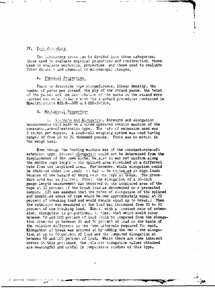
F~er- 'h.g:the i-stLrag ma.-hirie was eof the constant-rate-~of-exteenaio- type, pels/: onpati,, oulld not. be determined fromn thedisplac:eirineim cf the: ja7WS at~cn;e~ be..ai. i% wae not unifo.-m alongthe entir~e r-ope ler.glv, s~thpl iced aý,a st-et.:hed at a differentrate f:.om ýhe -*n_:-pliced area. PFir`,ernore~, wh~ile elongation couldbe obser-xd -cnder _cx ,.cad_ :ý had -so; be Qira ~ed at high loadsbeýýause of 'mne haza~zd of~ being reir '-.re ;-ope at.. break. The proce.-duz-a ku---d wAi as f.w Firs'l - 'he el onga'sior4 of a 30--An~.:hgauge lengtn -ireasurernen-ý. was, obser-ied oii -rne -CnVSplic ed area of therope a-.t 20 parcent.- :: the b0reak lc'ad as deteirmined on a pretestedsamp.le. (It was assumed that -.he ratles of olongation of the splicedand unspli ,-ed areas of z-ope woatid be: ore app-rcimrately equal at 20percer.,, of loreaking load and would rer,'afn s-:p~a1 up toc. break.) Thent~he ster..lPri was measured -:: the load wa.z incieased from 20 to 50per..er't, of irne b-reaking load. in.awith a i.-ns-tant rate of exten-sion. alongatior- is prn-portA~ia2.. "., 1%isa tha which would c~ccuxbeivee- c0 and 100 perz ant (cf load cud b3. .~omputted from the elonga-tion; (-Jbe::-7e ati between 20 and 50 't:etof' Load crn the basis ofthe :,ela-tive di'ee±eir ---he *:ime zixtar7als required foz'ý each,Elongatior: at break was arr:.ved at by --ddizg the twc- - the elonga-tior. at up to 510 per-enru of !2&ad and 's-he .;amp.i.Tesd elongat-ion atvbetveen 50 an~d ICC pe:-can-, cf "Load. While There are some inhexent4errors mthis p~z,'c: edure. ýhe e_:'A i~ ie~ongati on -values obtainedaie meankingful and uaa2ful in :-npat;vj~'~dle.s of Lthis type.

TA order to adjust the streif-Ih values for the diffcrent sizcsand wýA -hts of' the ropes, "breakin, len-th" was also conp ited toexpre~s- the breal1!.ng stren--th in tcr.ns of the leng-ýth of rope, thewei,' h of' w~iich would equal its br. a!k.*hg strength (i.e. , brc.akin,
L-. addition, the percenta _ of stren7,th loss wsc,)nutced baset.:
1) upon a standard break.Ln _en~th of 10,000 Lcc-t, whichL~s the usual -rua',!n_- 1,. .th for nylon 66., type 300)
2) upon the breaking- leni t;- o-- the unused control Arope(T-916)
2. Eer~-aAbsurbinAIlJit- From the elcn-cation arndbreakin1 srnthda, ky- f ollo -ig cnergy paramreter.-i -%%ere computed:
1) encrz:-, in foot- -, ,tnds r( c,-, Ied to stretc!' one fLoot ofropne to rauoture
2) oner.,i! in foot-ý':cunds reC~ired to stretch .'ne :)ound ofrope to rapture
3) p rccn'tate ener-v loss based upor tl-e sti'iCare foot-poainds (23,BC00) reatiired to streto-h one o nylon,tj.ne 3',0 to n',Tu+xrC
4~) ler -entage enor-: lcs'u, sed upon the foot-poundsreciired to strLt'%ch onc pound of the unujst,,. con-trol tori'pture.
3.1hrdness. 7"-e test for hardn.ý.s (')) rn~s b-ased upon t.,eforce necessar,) to oppen t"',e rore, by naeans of a mirai~incspike, suffic-luntly w~ide tý) nhow one;r;rn to bue passed throu. > The z Aike.ras l14 ineches 1_ arid h: f, a 5/3-inch taper per -i,-ot and a spatu1,-tCend for stv'rt*-n theoCr~ 0.L-. Th e s,)ike was Inscrted --- nuallybetween -the ro vstrands 2.r'til t ic rounded erd .r ktru~ded. The ropewith t'he ',sertedl spike s then mounted in a h,-iraiu.L1.c colr.:ressionm~achine o:zerct-'Jv !,t a rate, of 6 'nches ,er ininute. "11c loadnecess-ry to spread tric. ro :.c strands to a :iiam-cter of" A1/-inch was;-icasured. '.,"-.e re, ortea valves r. .resent the avcra *-c.s o2L three:icasuirL ocnt~s ta'cI'o 5 feet _-'art in, each ro~c. The n .:,r.%t s isshovr, -In .- r 2.
i.St-*ifness (Ieidin-, lonath)XAn inc....:,. of-. t'e -orcei%.' .2rea to be:-6 .20)0 in ý' ixcction noi,'v1 to i-ts o~i-r zLxis, as
bsis for cxrmar-.onP w't- '-'-c baroness teSit, i as nrri'.ed at byi csof tl~e Pi-k'ir Canti.L* Test (6). The rc, saJc was
).Oweo to slide -arnlc isas alon ahr*pploafr'
,*'.~ --

I
When the tip of the rope extending beyond the platform was "depressedunder its own weight to the point where the line Joining the tip tothe edge of the platform made an angle of 1l-1/2 0 with tho horizontal"(6), the length of the overhang was measured. One-half of this lengthwas taken as the "bending length" of the specimen.
Figure 2. Apparatus used in the nylon rope hardness test
5. Knotig Abilit. Various types of knots are used inclimbing but th setal c arcteristic of e 4ch is that it musthold when stress is applied. The knotting behavior of a rope dependsupon its stiffness and its coefficient of friction at the surface.Because stiffer ropes deform less during knotting, they have lessbearing surface and a lower coefficient of friction. Since the sameelertents are involved in tying and untying a knot,, in the interest oftesting simplicity only that force and energy required to tie a knotwere evaluated; it was assumed that the lower the force required to
tiaknot the greater would be the ease with which the knot wouldho-
I M"

I
In the knotting test, a 24-inch length of rope was tied looselyinto rn overhand knot. The two ends were inserted into the upperand lower jaws, respectively, of an Instron tensile tester, using agauge length of 10 inches and a cross head and chart speed of 5 in./min.The force required to reduce the greatest dimension of a loose knotto 2-1/4 incies was recordedp using a cardboard template for measuringthe distance. Corresponding measurements of energy were made by meansof an integrator coupled to the Instron output.
6. Compressibility. Since it was apparent that the knotbehavior test, using a con. tant dimension, is influenced by ropediameter, a compression test was devised which is related to boththe stiffness of the rope and, as a corollary, to the force requiredto knot it. In this test, rope diameter was measured by compressinga flat segment in the Instron with a force of 5 pounds and recordingthe resultant thickness. Then the rope was looped in a vertical planeand the end of the loop inserted between the flat jaws of an InstronCompression tester, having a diameter of 3 inches, so that the edgeof the loop reached just to the center of the jaws. At the cross-head and chart speed of 1 in/min. the force and energy required tocompress the loop to a value of 2-1/2 times the rope thickness wasmeasured. In order to maintain the loop in a vertical plane and toprevent the upper part from sliding to the side of the lower part,the rope was supported by hand. In this test, the stiffer the ropethe greater is the force and energy required to compress it to thefinal dimension. The energy-absorption values reported are subjectto a small correction because the weight of the loop of rope affectedthe sensing jaw and also because of the slight force that had to beapplied to it in order for some of the stiffer ropes to fit withinthe specified 3-inch gauge length.
C. Deteriorative Change
1. Fiber Abrasion. A 5-inch length of rope (equivalent to3 turns) was selected from that section visually judged to be theworst from the standpoint of abrasion. This length was carefullyweighed and unlayed and the individual fibers combed put. The brokenfibers were separated from the unbroken fibers and weighed. Theweight of the broken fibers compared to the weight of the original5-inch length of rope, expressed to the nearest five percent value,constituted the measure of fiber abrasion. In conducting this testit was assumed that those fibers not remaining intact through threefull turns would contribute to a weak spot in the rope and consequentlyto a loss in strength. This test will measure only the minimumamount of rope damage, since many of the ftbers are weakened but stillintact after at- ni and are thus not included. On the other hand,it is possible that testing would include some fibers that might havebeen ruptured from causes other than abrasion, such as by local ten-sile failure, fatigue failure, or cutting.
8
-- w - -.- ~.

* I
•, Chanaes Deter-ded b..,a_ Mi-r~osop .and X-RayStuy2. Tne chemical and mic2rcs:opic damage in expused nylon ropesis difficult to assess be-ause of -.he -T-Ap-td h,-nges that o-c:'- andthe different rates of T-hange between the fibers on the outside andthose in the core of tne rope. The cuter -avers -hange the msv,r'apidly. the fibers in the core may remain relatively sound evenafter long periods of expos~are.
Among the many tests used for determining the extent of deteriora-tion of nylon following exposure to sun. ight ar'e those that measurethe increase in the fluidity of dispersions of nylon in formic acidor meta cresol. In tnls study a simple:' procedure was also usedinvolving the measurement of the extercn cf the solubility of thenylon in a ferr:- chloride solation. Twenty gram sections crf variousareas of rop werefor 30 minutez in a 3 percent ferricchloride solution at a temperature jjt .nder -.he boiling point.The nylon was washed wiTh 1/!2 percent hydi .r-hloric acid and thenneutralized am.t1'amonia. rnLsed. and dried.
As a separate phase of this study h • wei- madeon the two Bates ropes a-, lOX and 200X iZ-how" gross areas of wearon t,.e surface and changes in the morphology of the singie nylonfilaments.
Also., X-.ray diffra-tion pa terns of fiber b-,i.ndles remored fromthe dawaged and undamaged areas of -,these ropes were photographed todetermine whether the orientation of the , rystals or the crystal6tructure itself was altered by -Their use history.
In addition, f.±uadi.nid determinations . 7 in 100 mi. of 90percent formic a.i.d ween made on dispersions of 11 gm of nylon fiberstaken from damaged and undamaged .ections of -.he Bates ropes.
D. Coxtelaticn Analjsi
In or•der to relate the change in observed properties with thehistory of the ropes in terms of days of u~e and severity of use. aUse Index was developed and applied to eaczh rope)based on informationsubmitted by the climbers. If the number of days of use was furnishedon a monthly or a yearly basis, these d :,.a were summed and correctedfoo qualitative sta.tments of severity, If the number of days wasnot given. t.he length of use was est•.•mated ba:ed on the qualitativestatements alone. The Use Index was acnputed by thzee individualsto whom the results of the obje:-tive test: had nct been made available.Correlation studies were made based on 'the Use Index' the age inyearz and 5he produJ t of the Uce Index and the age in years.
C-

The average results and the standard deviation (Tables I-VII),as well as the linear correlation coefficients between the variables(Tables VIII-X). using a WIZ Program (Appendix D) devised for aGE 225 computer, were computed for each set of objective measurements.
V. Test Results
A. Physical Property Changes
The specification for the constructional characteristics ofclimbing rope is quite flexible. the major requirement being thatthe rope contain three strands. The circumference, density.. numberof yarns per strand, the ply of the strand yarns,, and the twist ofthe yarns may vary widely provided the mechanical performancerequirements of the specification are met. The experimental ropesprovided an unusual cross section of the possible variations inconstruction.
1. Circumference.(Table I) The ropes studied (exclusiveof the Bates) varied in circumference from 20 to 25 sixteenths ofan inch, with the average just under 23/16 (1.4) inches. The mostcommonly used military nylon climbing rope is 1-1/4 (20/16) inchesin circumference,, with an allowable tolerance of * 1/8 (2/16) inch(see military specification for nylon climbing ropes App. B). Thus,on the basis of the upper limi t: the maximum allowable circumferencewould be 22/16 inches., or just 1/16 inch less than the average valuefound.
The greater average circumferenc.e of the experimental ropes(and also of the control rope T-916), assuming they were within thespecification limit.s to begin with, could be due to either shrinkageor to mechanical factors occurring during use and producing fiber oryarn displacement. Shrinkage would result in an increase in lineardensity (weight per unit length) or. correspondingly, a decrease inthe foot/pound evaluation.
SLinear Densit.(Table I) Examination of the ¢;, /pounddata showed tht all of the eighteen experimental ropes measuredover the I'l fe:e/pound minimum specification requirement for 1-1/4inch rope zni Tucl. .•bove the requirement when adjusted by the minustolerance of 10 percent for dyed rope . which would bring the figureto 15.3 feet/pound. Accordingly, the shrinkage explanation of theincrease in circumference mentioned above is not tenable. As amatter of fact, the length increase in the ropes probably occurredbecause of the use to which they had been subjected. If we assumethat the ropes originally had been close to the modal value of thespecification, th-n the most likely explanation of the increase incircumference lies in fiber or yarn displacement due to surfaceabrasion.
10
-7 -- 7

TABLE I
Three-Strand Rope Constructional Factors
Sample Number Circumference 1incnr Densitv(in- 16th -of -1nj 'Lt/7YI
(T-916) Control 23 17.6Special "A" (Bates) 24 18.4Special "B" (Bates) 23 18.1Experimental
2 23 19.13 23 18.04 20 26.35 20 25.36 24 18.67 22 18.98 22 18.19 23 18.110 25 18.111 24 18.112 22 19.113 22 17.714 23 18.115 24 19.116 22 19.517 22 18.118 23 19.119 23 18.1
Avg. of Experimental 23 19.3Std Dev. of Experimental 1.3 2.4
Specification Requirement 20 ± 2 17.0 (-1.7)for 1-1/4 inch rope
The eighteen used ropes varied in linear density from 17.7 to26.3 feet/pound. The average value was 19.3 and the standarddeviation 2.4. The greater length per unit weight than the specifica-tion minimum coupled with the greater average circumference than thenominal specification requirement (which would tend to indicate alower length per unit weight than was actually noted), leads to theconclusion that significant unrecovered elongation or permanent setmay have occurred during the use life of the majorit;ý of the ropes.Permanent set is not necessarily a shortccuing, since it is accompaniedby an increase in strength as a result of mechanical conditioning.However, a reduction in elongation, if reflected in a loss in energy-absorbing capacity. might be a serious disadvantage.
11
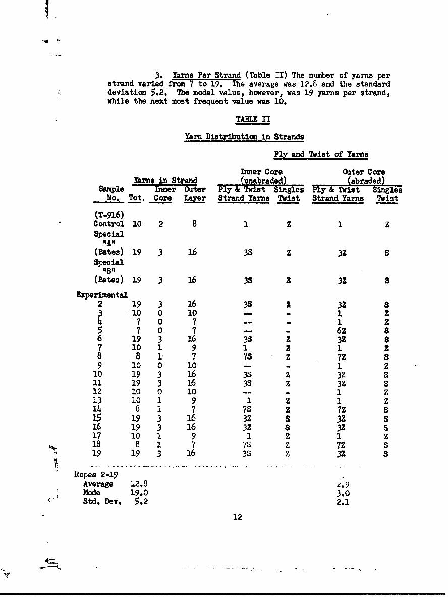
3. Yarns Per Strand (Table II) The nuimber of yarns perstrand varied from 7 to 19. The average was 12.8 and the standarddeviation 5.2. The modal value, however, was 19 yarns per strand,while the next most frequent value was 10.
TABLE II
Yarn Distribution in Strands
Ply and Twist of Yarns
Inner Core Outer CoreYarns in Strand (unabraded) (abraded)
Sample Inner Outer Ply & Twist Singles Ply & Twist SinglesNo. Tot. Core Laye Strand Yarns Twist Strand Yarns Twist
(T-916)Control 10 2 8 1 z 1 ZSpecial
"A"(Bates) 19 3 16 38 z 3Z SSpecial"B"
(Bates) 19 3 16 3S z 3Z s
Experimental2 19 3 16 37S z Z3 10 0 10 - - 1 Z24 7 0 7 --- 1 Z5 7 0 7 6 - 6Z S6 19 3 16 3S Z 3Z 87 10 1 9 1 Z 1 Z8 8 1 7 7S Z 7Z S9 10 0 10 -- 1 z
10 19 3 16 3S Z 3Z s11 19 3 16 3 % 3Z S12 10 0 10 -- -1 213 10 1 9 1 Z . Z14 8 1 7 7S Z 7Z S15 19 3 16 3N S 3Z S,16 19 3 16 3Z a N S17 10 1 9 1 2 1 Z18 8 1 7 73Z 7Z S
S19 19 3 16 3S Z 3Z S
Ropes 2-19Average 12.8Mode 19.0 3.0Std. Dev. 5.2 2.1
12
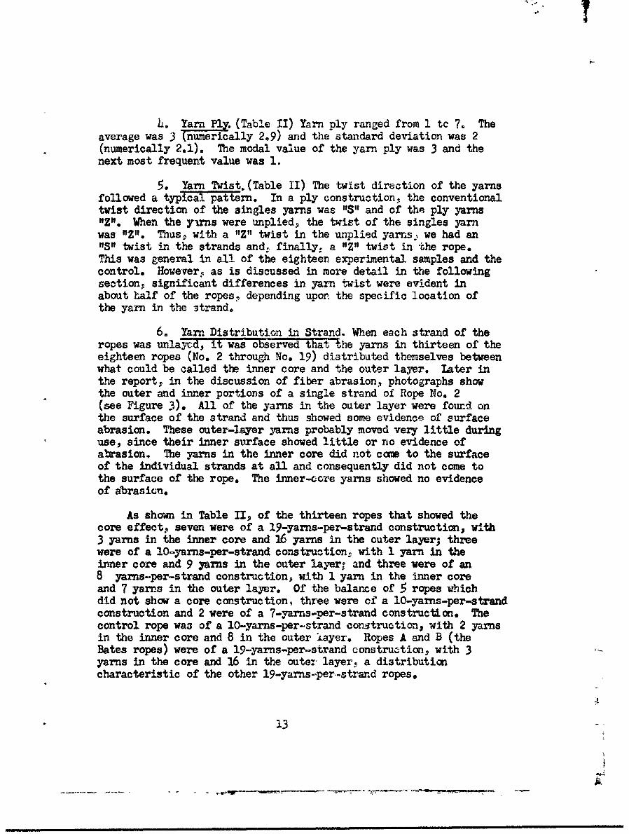
L. Yam a. (Table II) Yarn ply ranged from 1 to 7. Theaverage was 3 (numerically 2.9) and the standard deviation was 2(numerically 2.1). The modal value of the yarn ply was 3 and thenext most frequent value was 1.
5. Yarn Twist. (Table II) The twist direction of the yarnsfollowed a typical pattern. In a ply construction, the conventionaltwist direction of the singles yarns was "S" and of the ply yarns"Z". When the yums were unplied, the twist of the singles yarnwas "P". Thus, with a "Z" twist in the unplied yarrns we had an"S" twist in the strands and, finally, a "Z" twist in the rope.This was general in all of the eighteen experimental samples and thecontrol. However, as is discussed in more detail in the followingsectionp significant differences in yarn twist were evident inabout half of the ropes. depending upon the specific location ofthe yarn in the strand,
6. Yarm Distribution in Strand. When each strand of theropes was unlayEd, it was observed that the yarns in thirteen of theeighteen ropes (No. 2 through No. 19) distributed themselves betweenwhat could be called the inner core and the outer layer. Later inthe report, in the discussion of fiber abrasion., photographs showthe outer and inner portions of a single strand of Rope No. 2(see Figure 3). All of the yarns in the outer layer were found onthe surface of the strand and thus showed some evidence of surfaceabrasion. These outer-layer yarns probably moved very little duringuse, since their inner surface showed little or no evidence ofabrasion. The yarns in the inner core did not caoe to the surfaceof the individual strands at all and consequently did not come tothe surface of the rope. The inner-core yarns showed no evidenceof abrasicn.
As shown in Table II, of the thirteen ropes that showed thecore effect� seven were of a 19-yarns-per-strand construction, with3 yarns in the inner core and 16 yarns in the outer layer; threewere of a lOyarns-per-strand construction, with 1 yarn in theinner core and 9 yarns in the outer layer- and three were of an8 yarns-per-strand construction, with 1 yarn in the inner coreand 7 yarns in the outer layer. Of the balance of 5 ropes whichdid not show a core construction, three were of a IO-yarns-per-strandconstruction and 2 were of a 7-yarns-per-strand construction. Thecontrol rope was of a 10-yarns-per-strand constructionp with 2 yarnsin the inner core and 8 in the outer layer. Ropes A and B (theBates ropes) were of a 19-yarns-per-strand construction. with 3yarns in the core and 16 in the outer layer, a distributioncharacteristic of the other 19-yarns-per-strand ropes.
13
S .. . .. . .. .. ... .. . ... . •. •m• m,•mm~mmmamnm • ra m n mm m m m• • mz

It is of interest to note that in al; of the ropes (exceptNos. 15 and 16)that showed an inner coreiouter layer type ofconstruction in which plied yarns were usedc the direction oftwist observed in the inner core yarns was the reverse of thatnoted in the outer layer yarns. Thus. in the outer layer if thesingles yarns were 'IS" and the ply yarns were "Z" then in theinner core the singles would be "1Z" and the ply yarns "S". InNos. 15 and 16 the twist was the same in both inner and outeryarns.
The distribution of yarns between the inner core and theouter layer has considerable significance in terms of reducingthe effect of surface abrasion on the strength of the rope.As will be showtn later in this report (see Table x), there wasa strong correlation between fiber abrasion and strength loss.Since fiber abrasion occurs at the surface of the rope,constructioni in which the maximum number of yarns are situatedin the inner core wculd sustain the least amoumt of fiber abrasion.In the case of the ropes in which 3 of the 19 yarns were in theinner core, 15.7 percent of the total yarn substance was protectedfrom abrasion; this compares to 12.5 percent for the 8-yarn strandsand 10 percent for the 10-yarn strands . in both of which 1 yarnwas in the center. From this standpoint; the Control rope (T-916)is superior to the others. having ?0 percent of its total yarnsubstance in the center (2 yarns out of 10).
The rope manufacturer can exercise same control in thedistribution of yarns in the strand, The finer the yarns he usesin the constractiong the more yarns will form the inner core. Inaddition, during the strand-making operation, the locaticn of theindividual yarns in the register will determine which of theyarns will go tc the center and which will constitute the outerlayer.
The relative importance of the inner-core yarns in supportingstress and absoroing energy will depend upon the quality of theyarns used as well as upon the position of the yarns in the strand,particularly with respect to the angle which the yarn makes withthe long direction of the rope. The inner-core yarns that arerelatively straight as compared to the outer-layer yarns are thefirst to payticipate in the stress-support mechanism; theycontribute a higher level of stress-bearing capacity to the ropestructare. Howeverf if a considerable differential exists betweenthe elongation of the inxer-core yarns and that of the outer layer(if the inner elongation is less), then it is probable that, uponapplication of stress. the inner-ccre yarns will rupture first,since they reach their ultimate elongation before the outer layeryarns do. In this situation. the level of stress support thatcan be furnished by the inner yarns will be equivalent to the loadat which the elongation of the outer layer yarns reaches the rupture-
!4
:Ltj.mmm
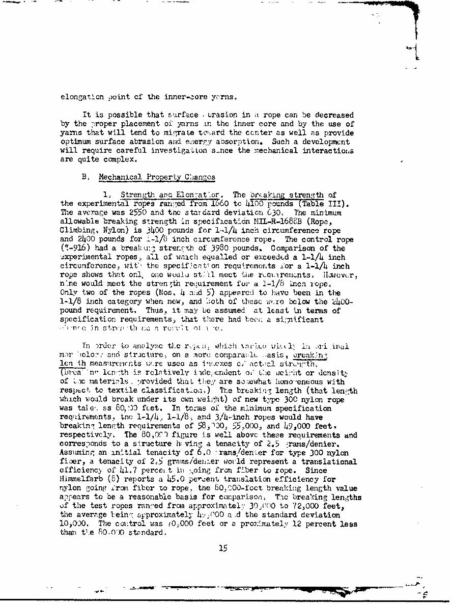
elongation Point of the inner-core yvrnso
It is possible that surface L rasion in a rope can be decreasedby the proper placement of yarns in the inner core and by the use ofyarns that will tend to migrate tc';',ard the ccnter as well as provideoptimum surface abrasion and enerly absorption. Such a developmentwill require careful investigation s-nce the mechanical interactiox'sare quite complex.
B, Mechanical Property Changes
1. Strength an- Elon-at'or. The brf-aking strength ofthe experimenta' ropes rancied from 1660 to 4100 pounds (Table III).The average was 2550 and thc n tardard deviatiCon 630, The minimumallowable breaking strength in specificatidn MIL-R-1688B (Rope,Climbing, Nylon) is 3400 pounds for 1-1/4 inch circumference ropeand 2400 pounds for 1-1/8 inch circumference rope. The control rope(T-916) had a breakh'r. strer.5•h of 3980 pounds. Comparison of theexperimental ropes , al of wnich equalled or exceedcd a 1-1/4 inchcircumference, wit', the speciflcrntion requirements Zor a 1-1/4 inchrope shows that orn., one wouali st '1l meet 'Liie rqiv.rermnts, ilxievur,n'ne would meet the strength recuirement for a 1-1/8 incn rope.Only two of the ropes (Nos, 4 a:id 5) appeorcai to have been in the1-1/8 inch category when new. and both of thesc w,.re below the -40O-pound requirement, Thus, it may be assumed at least in terms ofspecification requirements) that there had bee,. a si;nificant
ITr (-, r strcil -th zu. a r i' i i '
Tn )rder to arulyze tLe r.,; !iiLh •,iri..o uL.•l 1:1 J± i .iriaimar "!olocW anid stricture, on a more conpara:Il .,asis, oreak7n/lei -1i measuremirnts i;,.rc usea as in(.exes cY' actý,al sirL.rf-th,Tbna'n,- lcrr-th is rclDtively _i'iceecndent 0' L::e iei"'ht or dcnsit2 'of ,-ic materiels. provided thae tiey are so•ewhat homo'-eneous withrespect to textile classificatLo.,) Th-.e brfak~ih length (that len•thwhich would break under its own weight) of new type 300 nylon ropewas tal e%. as 60, )9) fcet. In tcz'ws of the minimum specificationreqluirements, tno 1-1/4, 1-1/8. and 3/h-inch ropes would havebreakitn7 lenF{th requirements of 58,))0. 55,W0, and 49,000 feet,respectively. The 80,rrl figure is well abovc these requirements andcorresponds to a structure h: ving a tenacity of 2.5 ;rams/denier,Assmning an initial tenacity of 6,0 :rams!den-er for type 300 nylonfioer, a tenacity of 2,5 granns/dei,:.er aoiJld represent a translationalefficiency of 41,7 perceiot in ý,oing from fiber to rope. SinceHimmnelfarb (8) reports a 45.0 perent translation efficiency fornylon going 'rom fiber to rope, the 80O,0-foct breaking length valueappears to be a reasonable basis for comparison, Thc breaking lengthsof the test ropes ranýed from approximatel:7- 30)O•O0 to ?2,000 feet,the average tein.- approximately 4,7,(00 a d the standard deviation
OO00. The cointrol was t•000 feet or a prox'mately 12 percent lessthan t'.e 0.OX)O stondard,
1-
- -' - '- ,- lImlll~ll ll ll lmll~lllll-~

I
TABLE III
Strength and Elonfation of Ropes
Strength LossSample Breaking Breaking based on BreakingNo. Strength Length Standard* Control** Elongation
(fty(%) - (%)(T-91,6) control 3,980 70,050 12 0 50.0Spe'cial W" (Bates) 2,850 52,450 35 25.2 50.6Special "B" (Bates) 3.370 61,000 24 13.0 50.0Experimental
2 2,125 40,600 51 42.0 45.53 3,1u6 56,200 30 19.8 47.74 1,725 45,400 43 35.2 45.65 2,050 51,900 35 25.9 50.66 3,265 60,700 24 13.3 51.07 2,375 414,900 44 35.9 54.68 3,280 59,40o 26 15.2 49.09 2,460 44,500 44 36.5 43.3
10 1,66o 30,050 62 57.1 40.8U 2,300 41,650 46 40.5 43.312 2.200 42,000 48 4o.o 40.013 4,100 72,600 9 -3.6 49.114 21o00 38,o00 52 45.8 50.215 3,000 57,300 28 18.2 45.816 2,700 52,650 34 24.8 42.617 3;000 54,300 32 22,5 42.518 2,000 38,200 52 45.5 49.519 2,500 45,250 43 35.4 48.8
Avg of Experimental 2,550 48,640 39.2 30.6 46.7Std Dev of Experi-
mental 630 10,300 12.9 14.7 4.0
Type 300 Nylon rope(Std.) miin spec req:1* in, circum, 3,400 35.0
1-1/8 in. circum. 2,400 35.0
* Estimated as 80,000-ft breaking length for type 300 nylon** 70,050-ft breaking length of T-916 control
16
*'--: -..... - •- -- • ---. . •- - •-'..•- ',-'-

Computation of strength loss, based on the 80,000-foot breakinglength standard, ranged from 9-to 62 percent. the average lossbeing 39,2 percent and the standard deviation 12.9 percent. Fourof the ropes showed strength losses greater than 50 percent, tenlost more than 40 percent, and 15 more than 30 percent. Based onthe T-916 control the average strength loss was 30.6 percent andthe standard deviation was 14.7 percent. Obviously. these ropeshad been subjected to a type of use that resulted in highlysignificant loss in strength. It appeared that a major portionc.f the strength loss could be explained by fiber breakage occurringas a result of abrasion. (See Results., Deteriorative Changes,Fiber Abrasion.)
The elongation of the ropes at the breaking point, or "breakingelongation'-MT717 I), as estimated from measurements made at 20and 50 percent of the ultimate strength, varied very little fromrope to rope. The range was from 40.0 to 54.6 percent, the average46.7 percent and the standard deviation 4.0 percent. The controlrope was 50 percent, or just 3.3 percent higher than the averagefor the used ropes. The reduction in elongation could be assoc-iated with the mechanical conditioning that the ropes had beensubjected to in use. As pointed out above (discussion on circum-ference): repeated loadings over long intervals result in aprogressive decrease in the amount of residual permanent set inviscoelastic materials. This decrease is usually accompanied byan irreversible increase in the length of the structure and acorresponding decrease in the rupture elongation. In experimentswith type 300 filament nylon yarn. Susich (9) found that elong-ation at break decreased from 21.4 to 15.8 percent after mechanicalconditioning for 50 cycles at 80 percent of breaking elongation.The immediate increase in length was 6.3 percent but this droppedto 5.0 percent after I hour of relaxation. In terms of generalorder of magnitude, the decreases in elongation noted for theexperimental ropes was consistent with that noted by Susich fornylon yarn. However. the length per unit weight of the ropes, incomparison with the control and specification requirements, appearedto be higher than could be accounted for by mechanical conditioningalone, particularly since the conditioning certainly must have beenat much less than the 80 percent level used for the nylon yarns.
2. Energy-Absorbing Ability. In mountain climbing rope,an important peformance parameter is energy.-absorbing ability,which is fundamental to the arresting of a fall (10). In a statictype of belay, the rope must completely absorb the kinetic energyof the fall. In a dynamic belay, friction of the rope sliding overa support absorbs some of the energy, reducing that which must beabsorbed by the rope in stretching. In either circumstance, thecontribution of the rope to energy absorption is a function of both
17
7-- PKPM-Tý -MPM4 qKb-4V

its strength and its elongation. If the stress-strain curve wereperfectly linear, the energy would be one-half the product of thebreaking strength and breaking elongation. Since the stress-strain curve in ropes is not linear, the energy equals the areaunder the stress-strain curve.
For the ropes in this test. the bre king elongations werequite uniform. The average value was 46.7 percent with a smallstandard deviation of 4.0 vercerin. Breaking strengths variedwidely. The average was 2 550 pounds and the standard deviation630 pounds (Table III). Consequently, -the variation in energy-absorbing ability was related more to the variations in strengththan to the variations in elongation.
Because more energ- is required to stretch 2 feet of ropethan to stretch i foot of rope, the energy results (Table IV)are given in terms of foot-pounds per foot or,, as an alternative.,of foot-pounds per pound of rope. The average energy expressedas foot-pounds per foot was 444. with a standard deviation of 138;the average energy expressed in foot-pounds per pound was -486,with a standard deviation of 2434. The coefficient of variationfor foot-pounds per foot was 31.1 percent and for foot-pounds perpound 28.7 percent. Equivalent coefficients for breaking strengthand elongation were 24.8 and 8.6 percent. The relatively closeragreement between the coefficients for energy-absorbing abilityand breaking strength than between the coefficients for energyabsorption and elongation would tend to confirm the observationthat the changes in strength during use influenced the energy-absorbing ability of the ropes to a greater extent than did changesin elongation.
Energy losses, computed on the basis of the 23:800 foot-poundsper pound energy-absorbing ability of nylon 300 at a breaking lengthof 8QO00 feet ranged from 44.0 to 74.6 percent, with an average of64.4 percent and a standard deviation of 10.2 percent. Energylosses. computed on the basis of the T-916 control rope 9 rangedfrom none at all to 68.3 percent, with an average of 33.0 percentand a standard deviation of 20.1 percent. In fact, one of the usedropes (No. 13) had an energyo-to-rupture, in terms of foot-poundsper pound, that was 6.1 percenr greater than that of the controlrope. In terms of this fundamental concept of rope performance,many of the ropes had reached the point where their serviceabilitywas seriously impaired and where they should have been withdrawnfrom service.
18

TABLE TV
Energy-Absorbing Ability of Ropes
Energy Loss(based on (based on ft-
23,800 lb/Ib of T-916ft-lb/lb control)standard
Sample for typeNo. Energy to Rupture 300 Nylon)(ft "Ib/ft) (ft-lb/Ib) (70)" M
(T-916) Control 714 12,566 47.2 0Special "A" (Bates) 513 9,1439 60.3 24.9Special "B" (Bates) 622 11.258 52.7 10.4Experimental
2 316 6,036 74.6 61.73 547 9,846 58.6 21.614 306 8,048 67.2 36.05 389 9,842 58.6 21.76 61I 11,923 50.0 5.17 475 8,978 62.3 28.68 549 9,937 58.2 20.99 326 5,901 74.6 53.0
10 220 3,982 83.3 68.311 360 6,516 72.6 48.112 319 6,093 74.4 51.513 753 13,328 44.0 -6.114 367 6,643 72.1 47.115 598 11,422 52.0 9.116 511 9,965 58.1 20.717 478 8,652 63.6 31.118 364 6,952 70.8 44.719 480 8,688 63.5 30.9
Avg of Experimental 444 8,1486 64.4 33.0
Std Dev ofExperimental 138 2,434 10.2 20.1
19
S_ •• : -- : . -,-:- - Im, m -'2

3. Hardness. Hardening of rope i• not necessarily anindication of deteriorationi it appears to be related to changesin physical properties arising frcm the interaction of complexforce systems. It is believed that, under same conditions,hardness may increase during normal storage as a result of aprevious history of heat-setting. The extent of heat-setting,in terms of time and temperature2 may influence the amount ofhardening which occurs but no studies have been conducted torelate different degrees of heat-setting with subsequent hardening.The hardness of the experimental ropes ranged from 17 to 140pounds (Table V). The average was 52.2 pounds and the standarddeviation 27.2 pounds. If the high value of 140 pounds iseliminated, the range of hardness was from 17 to 69 pounds.Undoubtedly, the 140-pound value indicates that this rope wassisnificantly different from the others.
Although hardness does not appear to be significantly relatedto deterioration, it is certainly important in the functioning ofthe rope. The subject of hardness and its significance andrelationship to rope processing parameters deserves attention andshould be investigated in detail. (For a related study, seeAppendix C.)
4. Stiffness. The stiffness (bending length) of theexperimental ropes ranged from 3.66 to 8.58 inches (Table V). Theaverage was 5.90 and the standard deviation 1.43 inches.
The relationship between hardness and stiffness is rathercomplex. While hardnnss, as measured in this study, involves acentripetal-type force which is directed toward the central axis ofthe rope and must be overoame by the marlinespike as it is forcedbetween the strands, stiffness represents the ability of the ropeto bend under its own weight. In this series of ropes, where thelinear density range was narrow. the major factors determiningstiffness were inherent in the fibers and in the rope structureitself, hence both these factors contributed to hardness as well.
The association between hardness and stiffness is demonstrated,by a coefficient of correlation of .57, of which 32 percent of thevariance is explained by the relationship between the two variables.This modest cor-elation indicates that common features must haveinfluenced these parameters.
That other variables also exerted an influence becomes veryevident when one compares the hardness and stiffness of '~jo No. 17.The hardness of this rope (140 Ib) was much beyond that which wouldhave been predicted from its stiffness.
26

All of the ropes were stiffer and all but one harder thanthe control, which emphasized that stiffness and hardness arefunctions of use and storage conditions. It is not obviousfrom any of the data what the intrinsic cl.anges in the ropeswere which led to the marked increase in hardness and stiffness,but two of the factors that might have been responsible werechanges in the fiber from exposure to the elements or fromstorage, and compacting of the fibrous structure in the yarnfrom weathering, shrinkage, or mechanical conditioning. Adetailed study should be made of the mechanism of stiffeningfollowing processing, use, and storage in crder to determinethose design parameters which caild slow down the rate atwhich stiffening occurs.
5. Knotting Abilit. The maximum force required to tiean overhand knot in the ropes ranged from 7.-D to 81.5 pounds(Table V). The average force was 3307 and the standard deviationwas 19.1 pounds.
On the basis of a 24-inch length of rope tied into a 2-1/4inch knot, it would be expected that the effective distance, whichis the controlling factor in energy consumption, would be relativelyconst2nt. For the greater part of Uht. knot-tying process, thiswas the case and tI maximum force build.-up did not occur untilthe end of the test. However, the value of the dimensional changesoccurring near the end of the test varied appreciably from ropeto rope and led to energy, consumption that was not exactly propor-tional to the maximum recorded force. The energy consumed rangedfrom 16.05 to 182.40 inch-pounds. The average energy was 72.30and the standard deviation was 42.30 inch.-pounds. The control roperegistered lower in maximum force (7 lb) and energy consumption(10 in-lb) than any of the experimental ropes. so, again, use wasfound to increase the test values.
6. Compressibility. The compression data obtained franthe ropes appears to be closely related to the knotting data. Thecompression force ranged from 9.5 to 39.5 pounds. The average was19.6 and the standard deviation 8.6 (Table V). As was noted inthe knot tests, the control rope had the lowest value. Thus itappears that all of the factors relating to the inherent mobilityof tVe rope structure are influenced by use in mush the same wayas are the strength characteristics. Accordingly, from thestandpoint of rope efficiency, .t would be expedient to pay moreattention to achieving a structure in rope design that, withcontinual use, will sustain the least amount of strength loss andthe least increase in stiffness.
21

4l)
4304.,
00
> 00 C- CYS 0 O D33! CO~AC- CN CAr-r; 0-O
4.1-4 0e . ~ ~ * . o ~ a e
E8-
0
0- 1y041 Q ,OD&'
0 , -0 4 n~om c %4D I^ CN (nIi~ NA O NJ' %OI nOIA Oi it
H H' H
43 :
-04 4L OA0 00O OOOOOIOO-% OIA 0 0OIAIAO1A043) IV.. * . . * **** 0; -
E0
go
4)
L : H 9- C.- H-..CC JOtgq~~~' 'D I^~1 AOC-~ 't~ -A\ I H
NH 0
0 1,..M~H uS.o0\
22
-Ar- m

0. Deteriorative Changes
1. Fiber Abrasion. As pointed out under the descriptionof test methods 7 rarasion may be caused by many factors,but the ultimate effect is the same: the breaking strength of therope is reduced and there is a corresponding reduction in itsenergy-absorbing ability. Among the experimental ropes, the rangeof percentage weight loss was from zero for rope No. 13 (the rop.that had a higher energy-absorbing ability than the new control)to 45 percent. The average was 26.1 percent and the standarddeviation 12.9 percent (Table VI). The correlation coefficient
TAULL VI
Age, Use Index, and Fiber Abrasion of Eighteen Ropes
Product of UseSample No. M Use Index Iex md Age Fiber Abrasionki eas (fratr W (Hater 'W)-- " aight -• JIo-)*
Std (T-916)Conixol 0
Special "A"(Bates) 20
Special "1,q"
Experimental; 19 182 3458 403 16 109 1744 15h, 14 166 2324 305 11 150 1650 256 18 152 2736 157 12 200 2400 258 13 135 1755 109 16 95 1520 35
10 18 220 3960 40n 18 60 1080 3012 18 180 3240 4013 14 20 280 014 n 200 2200 4515 10 6o 600 2016 13 100 1300 1517 14 140 1960 2018 6 200 1200 4519 18 180 3240 20
Avg ofExperimental 14.4 141.6 2040 26.1Std Dev ofEprimental 3.6 56.8 1010 12.9.Rounded outo nearest 5%
23

betweenov st+re~ngth Ios eu nr! N~b ha ml%ý i As a hi gh 0-8? P7-f IA. i #hover 75 percent of the variance could be explained in terms of therelationship between the two vnriables.
A detailed analysis was made of rope No. 2, which had a strengthloss of 42 percent, to account for its high loss in view of theabsence of sinificant ultraviolet deterioration and only visualevidence of surface abrasion. From the ,ross appearance o2' this rope,it could be concluded that only a small portion of the surface fibershad been seriously abraded and that a substantial core of unabradedfibers should exist. But, when the rope was unlayed and each stra-dwas untwisted to show its inner structure: only three of the nine-teen yarns comprising the strand were found to be free fram abrasion(Figure 3b). The balance of sixteen yarns all appeared at the sur-face of a short portion of th• rope, due to migration of the ymrnsin the strand and to the path of the strand in the rope structureitself. Thus, fiber breakage at any point or: the surface couldseriously influence the strength of each of the sixteen yarns andconsequently of the whole strand and rope.
2. Nylon Fluidity and Ferric Chloride Soluoilityo Thenylon fluidities obtained from different areas of the Bates ropes(A and B) and from the control rope are given in Table VII Rope Ashowed an avwrage increase in fluidity of 0.1 rhes and rope B of0.2 rhes. Neither of these increases is indicative of chemicaldeterioration. Because a comparison (11) of tensile loss vs. fluid-ity for nylon tapes that had been exposed to sunlight (ultra-violetradiation) revealed that fluidity at this level is not reflected inany strenýth loss, the strength loss and hardness changes observedin these two ropes must have arisen from causes other than exposureto sitnli:ht.
TABLE VII
Nylon luidity£of "Bates" Ropes(rhes)
Rope A Rope B ControlInside Outside Inside Outside Inside Outside
area- •... ) 1.5 1.5 1.6 1.7 1.4 1.4
a r, 1.5 1.5 17 1.5
24

a. Outer portion
b, Inner portion
Figure 3. Outer and inner portions of a single stran~dof rope No, 2, showing inner core octistriaction

Alli o f tL c' w e s in *hj -r-c1. -1ss th.an. 5 percent oftheir or~n L-wht Ln the ferric chJ'oridc solulbil:ty test.; th- s
indicates no .5i,-1n:i'.fcant weat~heriri dnrnr;o.ý It iz; prolb,.blc thK..,if' the ft-rri-c c,`ort&; te-st hand been li~iitued to th.c uutor Ji',c'.-s of
the rope, hi:;her solubil-ties would have 1jecn measured, H~owevier.,since gross deterioration of' the rocpe str~irture was the majo,
cteonoinero-t., it is assiumed that weatherin,,: d-id noG, have
an arnportant inf~ucxce on f~unrutional properties.
3z il',mcnt Structu.re Dama-a. Figu7 e i4 shows a lOxmagpni~ficatiCor of th~e :ontro1 rope (Fgre hia) and two Firnilarmnaific(-tions of ro-ý A. one (F~r 4b) teken fron an unnbradedarea rec.'r tlhe end o" tho rope. anc one, (i+,uo )t;Ier from anabraded ore-i, in t:!-o aLbr.-,,:. are-a of the_ rope~ 2i. :-,1L<o.nt..appear separatedi frar, thoc yarn body, The numirber o t!,e';5 1-la:rintSis a function of the degree of damage. Nlear- tho cnd cf the rope.,where it was not subject~ed -co any s: gnif-ircnt abi.2siotvc. action)~ very£sw sinja1 filnr!cntý, apr-eareci, -.iherea-, fre-a) thc abrrcied ar-n iany
-r~cn finic-cntr ;rcr e detc- ,edL
.V-L-ure a e`)`'?:'tvic )xosij i~~t removedfrom the control and rope A. The control rope (Figure 5a) showisperfct~ly urnifcr fill-ren~ts end no disturtance of the surfa.ce struc-sure. Ropu A (FI;,are b)shows evidence of a thi-ck'cnin-, at thebroker filt-xiert endfbiia~a of the fiber surfaCe, and. in som-.einstances not shown on the photog-raph.- there was a sticking togetherof broken filber sndsc.
4~. Changes in X-ray Dif'fra'>u,:on Patterns. Fi.,ure 6 showsX-ray diffracti-on pattern.s of fiber bundles re-ioved from. the controlrope and fror cOarnaged areas of rcpe(,s A and B, The pattern for thecontrol rope is typical of an oriented filber pattern of hi~rh tena-city nylon. WhileI the patilterns for -the other two ropes (A & 3)appear -.ci4icwhat. diii',ren-, f'rcm tha~t c: -,he control, It .s believedthat these 'Jiffo~rences m~ay have arisen more from the difficulty inhandling -cne damaged areas than from any effer-t on the crystallattlces- of +'-, n'-lon w)*,L_-h myhza\'e been indiuced by the iaria-e.For oya'n-7lr. tlie in-.erfcrco':E:-r, w½ imarc ,.-iptomatic,',f'4 ff~cul11-- 1rn theu 'rorý.,- an 1 ,, ~ c~ okcn fiberends! -.n(- re.-erce of' the (1 *,i fosc, Ltrftrnz, np'ttern ol" Che rope
1, &o belio-ý;c. to ble a zc-stin -K .
The rosu of th ae t: anravs1_e, -nar6 or, t o .atcs r'opescon'irmoed the evjdcnce of' the absence oi solar ra~diation clamacse inthe othner cl-hteen rope.s. "he photo ;rai,,hS alse confirmncd that therewas fiber breaka -e due to -abra si on and they showed the manner inwhich such br-eakag-e occvrs. Th1-i. breakage could account for theobserved loss i.. the st'ren-;th of the ropes. The X-ray data -.:,e not
indicative of any particular trend and no 4indicatiorns were found ofthe poss'ble carse of the CTiffenýTl- -)f' t"--' roeS.

Cw
06
4d
00
1010Lw
C.,d
0$443
04
27i
'W"5;F

C)
- ;)j
-l-, o-
4 ribI4
tq4
-IMN
Sig
t<•28

I
Control Rope B Rope A
Figure 6. X-ray diffraction patterns of fiber bundles
D. Correlation Between Objective Data and Use Histories
It was assumed, initially, that the extent of deterioration in theropes as measured by strength loss, energy loss, and fiber abrasion wouldbe a reflection of either the amount of use to which the rope had beensubjected or the M of the rope. It wa 7s--ound that age was not asignificant factor in governing deterioration but use history was (TableVI). The degree of correlation between use and objective measurementsof deterioration could have been influenced by a number of factors:the validity of the use history; the validity of the interpretation ofthe use history by the rater; and, of course, the significance of therelationship between the use history and the objective measures.
Eleven of the eighteen ropes had use histories that were found tobe quantitative; seven had histories that were more qualitative thanquantitative (Appendix A). Accordingly, correlations were made (Appendix D)using all eighteen samples (Table VIII) and only the eleven that had themore complete histories (Table IX). Three raters (W, P, and J) wereused to compute the Use Indexes of the ropes. They agreed that theIndexes would be arrived at by counting the total days of use using ajudgment factor if days were not explicitly stated. For example, ropeNo. 2, with documented use during a) three 1-month climbs (90 days)b) two climbs per month for 3 years (72 days) and c) occasional usearound the house over a 19-year period (20 days) would be consideredas having a use index of 182. Despite this understanding, agreementbetween the raters for the rest of the eighteen ropes was not good;the correlation coefficients of their Use Ind3xes were 0.24, 0.144, and0.65.
However, for the 11-sample group, which was based on more quantitativeuse histories, the correlation coefficients between the raters were 0.61,0.66, and 0.87. Using Fisher's Z-transformation (Appendix E) to testthe significance of the differences among these correlation coefficients,it was found that in the 18-sample study the three coefficients were notsignificantly different from each other, the greatest difference being1.6 standard deviation. 1-owever, in the Ul-sample study, the differenceswere even less, the greatest being 0.74 standard deviations.
29
- -- ---- ~ . -IWI

/
While, on a strictly statistical basis, the correlationcoefficients for the Use Indexes were not significantly differentamong the three raters, the corrmlation coefficients between theobjective test measurements and the Use Indexes were quite differentamong the three raters.
TA3•'; VIIT
Corrcl•tion Coetficicnts (aouvc 0.0)):ctween Use Index and Ubjectivc hcasurcs
of Livltecn-Rope Series
Rater (W) Rater (P) Rater (J)
Use Index
Rater (W) 0.65 -Rater (P) 0.65 -Rater (J) - -
Breaking Strength (lb) -0.65 -o.55 -
Breaking Length (ft) -0.65 -0.52 -
StLogt ss (M)B9i oWn---6,000-ft 0.66 0.51 -
Based on breakinglength of T-916 cantrol 0.65
Energy to Rupture(ft-lbift) -o.57--
(ft-lb/lb) -0.53 -
hergy Loss (%)Based on 23.800ft-lb/lb o.54 - -
Based on ft-lb/lbof T-916 control 0.5h
Fiber Abrasion (Go) 0.60 0.55
Notez (-, indicates a correlation coefficient below 0.50.
The correlations were based on those characteristics that appearedto be related to deterioration, i.e., changes in strength and energyand in the amount of fiber abrasion. (In a preliminary trial, haronessshowed such poor correlation with the Use Index for all three ratersthat correlations were not made for it or for the related factors ofstiffness. knotting c0aracteri stics, and comDression.)
30
41--
--
A -
TABLE IX
Correlation Coefficients BetweenUse Index and Objective Measures of
Eleven-Rope Series*
Rater (W) Rater (P) Rater (J)
Use Index
Rater (W) 0.87 o.66Rater (P) 0.87 0.61Rater (J) 0.66 0.61
Breaking Strength (lb) -0.72 -0.73 -o.53
Breaking Length (ft) -0.72 -0.71 -0.62
Strength Loss (%)
Based on 80,000 ftbreak ing length 0.72 0.71 0.62
Eherwy to Rupture(ft-lb/ft) -0.72 -0.70 -0.60(ft-lb/lb) -0.67 -o.64 -0.65
Energ Loss (%)Based on 23,800f+-lb/lb 0.68 0.64 0.66
Fiber Abrasion 0.77 0.76 0.50
-T, el, '•-r~';c scrtcs; represented those ropeshlv ,, •, rt'tr, LIve use histories
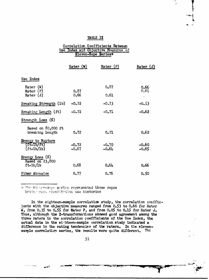
In the eighteen-sample correlation study, the correlation coeffic-ients with the objective measures ranged from 0.53 to 0.66 for RaterW, from 0.35 to 0.55 for Rater P, and from 0.05 to 0.15 for Rater J.Thus, although the Z-transformations showed good agreement among thethree raters in the correlation coefficients of the Use Index, theactual data in the ei7hteen-sample correlation study indicated adifference in the rating tendencies of the raters. In the eleven-sample correlatici series, the results were quite different. The
31
AW'pm

correlation coefficients ranged from 0.67 to 0.77 for Rater W, fromvou 0> fo ,ptr
1.4k to.-. I- or Rater P, and from 0.50 to 0.65 for Raer J.Obviously, the correlation coefficients improved when the Use Indexdata were more quantitative.
When the good correlation of the eleven-sample series is takeninto consideration, and the relatively fair correlation of theeighteen-sample series, it becomes apparent that deterioration wasrelated to the use of the rope. Thus, it can be assumed that thelonger a rope is used, the greater will be its deterioration.
Using the data obtained in the eleven-sample series, it ispossible to find Use Indexes which correspond to different degreesof deterioration. These relationships could be used as a basis forestAblishing cut-off points in the use-life of a rope, beyond whichadditional use could become hazardous. For example, if a 30-percentdeterioration, in terms of stren2gth loss, is considered to be themaxi-mum tolerable amount from the standpoint of safe performance, itcan be determined by reference to Figure 7 that this corresponds to
280-
240".
200-o
a4
0
•. 40 CIRCLED VALUES REPRESENTAVERAG USE INDEXE..
S•.,NES TH'E RANGES.
0
o I I I I I I10 20 30 40 50 60
STRENGTH LOSS %
Figure 7. Correlation of Usc Index With strength loss(11-rope saries)
32
- q,- -

i
-3 a~ y -- T4J.L -~ d -1~ -,e -*1c -'~1 -
associated with climbing ropes and. after a fixed number of days ofclimbing use, the rope ;ould automatically be retired from service.However, the data in this report are not sufficiently extensive topermit an unqualified statement as to thc validity of the Use Index.Nevertheless, as an in:.txal control measure, it might be well toconsider disqualifyin-r ropes from further use after 100 days offield climbin- use,
As mentionedý correlation of the various objective measurementswith the chronolog2.cal age of the rope in years was not meaningful.The correlation coefficients found for strength. abrasion, andenergy ranged from a low of 001 to a high of 0.24. The age ofthe ropes ranged from 6 to 19 years (Table VI), with the averageage being 14.h years and the standard deviation 3.6 years. Five ofthe ropes were 18 years old, causing a clustering of values at thisage that might have added to the difficulty of finding a correlptionwith age. Nevertheless, there was a sufficiently broad range ofages to demonstrate that age alone cannot oe considered the chiefcause of degradation. When the Use Tndex and age were multipliedtogether, a factor was obtained which showed a better correlationwith deterioration than did age alone. This would be expectedbecause of the high correlation betwefn use and deterioration.There is no basis for assuming that any real interaction existsbetween a-e nnd use 1history.
E. Correlation Between Objective Measures
Some of the correlation coefficients obtained between theobjective meaFnurements made in this study (Table X1 are discussedin general terms belcws
1. The knot tjnL, force (in pounds) is significantly(r value of 0.93) related to the knc t energy (in inch-pounds)required, and somewhat (r value of0.69)related to the compressionforce.
2. T.'( kt c,,scrL- is fairly clrsely (r value of 0.78)related to the cn, , !q irud to compress a loop of rope cpMressionenergy. Apparently knotting involves a complex interaction of tensile,compress`ve• and bending forces, which make the prediction of knot-holding ability rather difficult.
3. The force (in pounds) required to zompress a rope to2-1/2 times ifs thickness (compression force) is significantly(r value of 0,93) related to the compression energy (in inch-pounds)required. The high variability of the ropes in strength and thelow variability in elongation, making energy differences more closelyrelated to strength differences. appears to carry over to the knottingand campression data also.

. iHardness is fairly closely assoc•_ated with both thecompression en2ri 6 ) and compression iorce (0.66), but iss~li'g.ty less closely related to bending _lýt (stiffness) (0,57).Tc fact that so -,mny of tihe correlation coefficients related tolhari..css, bending length, and knotting characteristics are eitherhighly or fairly significant suggests that these para,.ieters couldprove to be a fruitful area for furthcr study. It is probable thatmore intensive analysis 'ould provide clues to the serious problemof ivpe stiffenin- anu the rea..ction in knot-holding ability,
5. Tho s-gni.t'icant cor:relation between strengcth loss andoner-y loss (0.7) provides fwuthjer evidence that deterioration ofthe ropes was a result of changes in strength and not in elon-ation.In addition, the equi~aient corrolatf'on (r value of OJ7) betweenstrength los• anu fiber abrasion enables us to conclude tihat thestren-th loss sustained by the rope _as a direct consequence of thcsurface abrasion of individual fi'2ers, and that their cuttin7,fracture, and ripture was trarsLated into a correspondin-,t reductionin stren-th.
6. The inverse relationship (-0.69) between circumferenceand linear density may have so:.e significance. The fact that it isnot even higher indicates that some external factor, such as theobserved surface abrasion, must have been operating to increasethe circumference of the rope without a corresponding change in itslinar densit-r.
TABLE X
Correlation Coefficients Between Various Objective -Neasuresof Eighteen-.iope Series
Knot Knot Compres-Tying Tying sion Hard- Strength Circum-Force Ener T Force ness Loss ference
Knot tying encrgy Qz93
Compressio•' E.nc.: --. *;b •.• 3>('
(. r'. .' : c .• ' orce C. -16
zt -i nr. s
Energy loss 0.67
Fiber abrasion 0087
Linear density -0,69
3,4

I
VI. References
1. Chapins John W.. "Stiffness Evaluation of Rope, Climbing,Nylon". Tex Eng Lab Material Examination Rept 2707, QMR&E Command, Natick. Mass. (1956)
2. Stephenson, C. V. and W. S. Wilcox, "Ultraviolet Irradiationof Plastics. IV: Further Studies of Environmental Effectson Films and Fibers", JPo!ýmer Science, Part A, Vol I,2741-2752 (1963)
3. Letter from OQMG to Dr. S. J. Kennedy of QM R&E Command,Natick, Mass. Code QMGREP 3 March 1959
4. Letter from Mr. A. E. Peterson to Col. A. H. Jackman.Subject: "Shipment of 18 climbing ropes for tests",28 February 1959
5. Specification MIL-R-17343, "Rope, nylon" (Paragraph 4.2.5.5)
6. "Tentative Method of Test for Stiffness of Fabrics-D1388-55T"ý, ASTM Standard, Part 10, 581, 1961
7. "Chemical Methods for Textiles", Tex Func Fin LI- Rept 170,QM R&E Command, Natick, Mass. (1957)
8. Himmelfarb, David, "The Technology of Cordage, Fibers andRope", Textile Book Publishers. Inc.., New York 1957
9. Susich, G., "Mechanical Conditioning of Textile Fibers",Textile Research J, 2_3, 545 (1953)
i. Wexler, A., "The Theory of Belaying", American Alpine Journal,7, 379 (195o)
UI. Miles, Thomas D., Conmunication, Oct. 1964
35

Appendix A
Individaal Use Histories
of Nylon Moute..n ClImbing Ropes
37JI-3
_
a• ~ "'i
al a . - | II'll l-
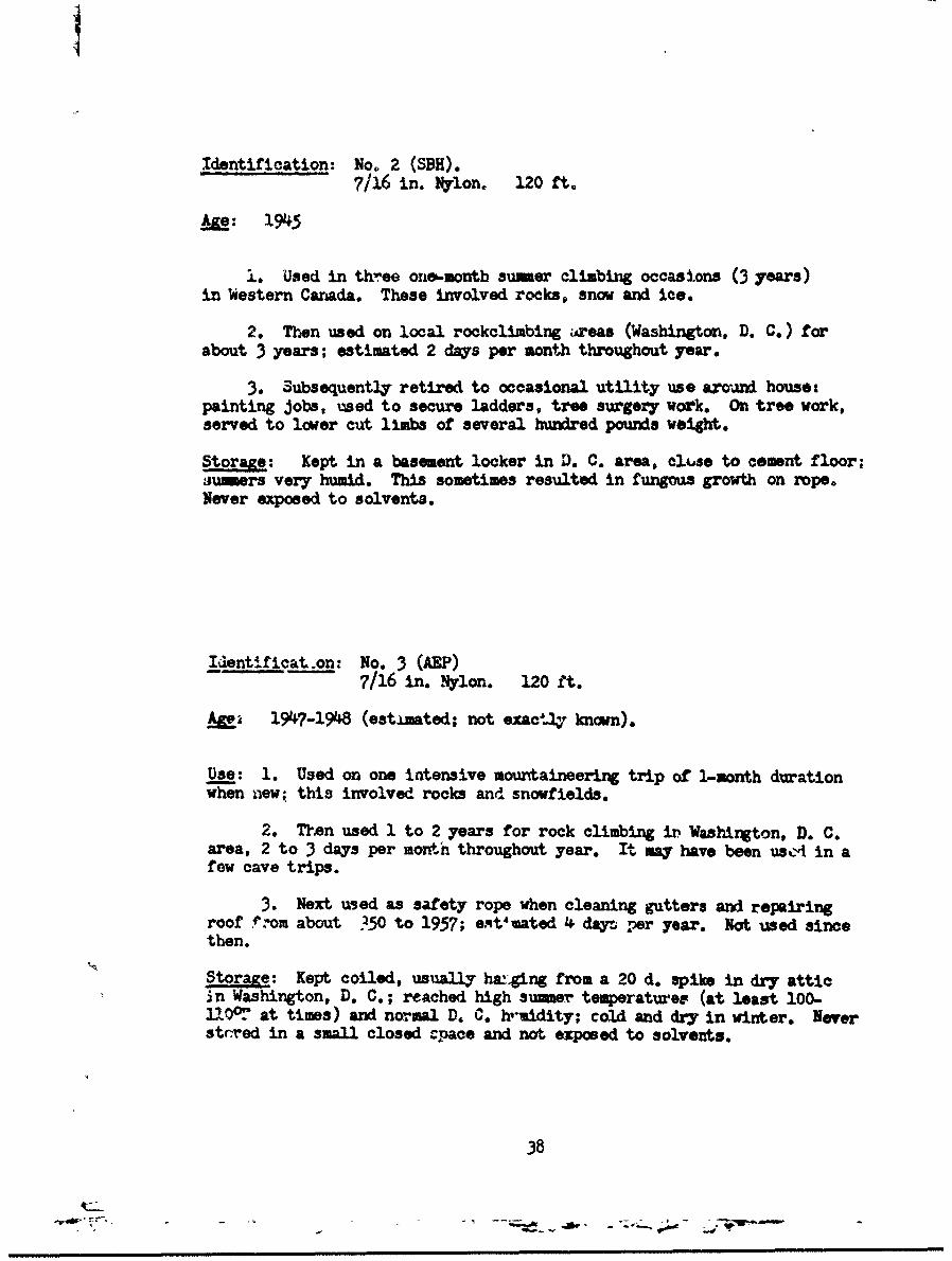
Identification: No. 2 (SBH).7/16 in. Nylon. 120 ft.
Mje: 11945
.. Used in three one-month summer climbing occasions (3 years)in Western Canada. These involved rocks, snow and ice.
2. Tnn used on local rockclimbing areas (Washington, D. C.) forabout 3 years; estimated 2 days per month throughout year.
3. Subsequently retired to occasional utility use aroum d house:painting jobs, used to secure ladders, tree surgery work. On tree work,served to lower cut limbs of several hundred pounds weight.
Storage: Kept in a basement locker in D. C. area, cl.se to cement floor;ju'eurs very humid. This sometimes resulted in fungous growth on rope.Never exposed to solvents.
Identificat.on: No. 3 (AEP)7/16 in. Nyon. 120 ft.
A&1 1947-1948 (estimated; not exactly known).
Use: 1. Used on one intensive mountaineering trip of 1-month durationwhen new; this involved rocks and snowfields.
2. TIsn used 1 to 2 years for rock climbing it Washington, D. C.area, 2 to 3 days per month throughout year. It may have been us'At in afew cave trips.
3. Next used as safety rope when cleaning gutters and repairingroof rom about 350 to 1957; eqt'vated 4 dayr per year. Not used sincethen.
Storage: Kept coiled, usually hanging from a 20 d. spike in dry atticin Washington, D. C.; reached high aunmer temperatures (at least 100-liQ0°' at times) and normal D. C. huidity; cold and dry in winter. Neverstrred in a small closed Cpace and not exposed to solvents.
38
4C-m

Identification: No. 4 (J!B)3/8 in. Nylon. 120 ft.
Age: Purchased 16 June 1950
Use:
1. Used as climbing rope 1950-1956 at local rock climbing areasnear Washington, D. C., approximately 2 days per month.
2. Used on 3 week expedition to Canadian Rockies (Iyells) in 1954.Much of this use was on snowfields.
3. Last used in 1957 as hoist to pull 14 ft. rowboat up steep bank.
4. Rope has never been used in caves.
Storage:
Sumer: Usually kept in clothescloset of a ground floor apartmentin Washington, D. C. area; occasionally left in car trunk during week.
Winter: Kept in car trunk.
Identification: No. 5 (I•I)"7/16 in. Nylon. 120 ft.
Ae: 1953
Use: Used quite regularly for rock climbing on week-ends for 3 years,in Washington. D. C. area. Climbers have been caught by it nr timesbut never in a severe free fall.
Storag: Generally stored in a dry and dark closet on second floor ofapartment in D. C. area. Occasionally, it has been left from one week.end to next in rear of station wagon.
39
i l - um I nn nu-nn~

I
Identification: No. 6 (MS)
7/16 in. Nylon. 120 ft.
AL: Early in 1946
Use:
1. Used extensively for weekend rock climbing in Washington, D. C.area,
2. Colorado Rockies in 1949 and 1950, about 1 south each year.
3, In 1950, it was lost in Colorado Mountains at 12,000 feet for10 days.
4. Also used for tree surgery and has been left in trees for
several days at a time on several occasions.
Storage:
Jenerally kept in an open ?lace (or. shelf) in dry basement, --normal D.C. humidity. Not stored in a closet and not expised to solvents.
NOTE: This is an Army rope bought a few months after World War II.
Identification: No. 7 (H. & J. K.)
7/16 in. Nylon, 70 ft.
&,.e: Purchased May, 1952 (odd length from an Aruy coil).
Use:
"Rope was put in service in June, 1952. It was used extensivelyin lead rock climbing for a period of five years. It held no bad fallsduring this time. However, the rock on which it was used is an extremelycoarse granite with high abrasive qualities.
"During this tima, it was used for very little ice and snow climbing,and consequently, has bad comparatively little wetting and fr-exing.
"Since retirement from use in climbing, the ro-e has been used forbelay practice. The belay practice rigging had a 6 in. sheave instead of
a carabiner for the rope to run over (a wooden sheave). The duna in use
weighed approximately 165 pounds. Twenty to twenty-five falls varying in
height from 10 to 20 feet of free fall, were held. The rope shows
scorching and fusing where it ran over the pulley in stopping these falls.
Storage:
"During the 6-1/2 years we have had the rope, it has been stored in
our truck. There it ha& been protected from rain and snow, but as under-
gotn extreme temperature changes. Temperatures in the truck have varied
from well over 100OF to minus 300F."
4o
4t_' ~ .
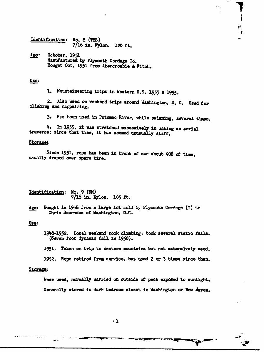
Identification: No. 8 (TM)7/16 in. Nylon. 120 ft.
Ame: October, 1951Manufactured by Plymouth Cordage Co.Bought Oct. 1951 from Abercrombie & Fitch.
Use:
1. Mountaineering trips in Western U.S. 1953 & 1955.
2. Also used on weekend trips around Washington, D. C. Used forclimbing and rappelling.
3. Has been used in Potomac River, while swiming, several times.
4. In 1935, it was stretched excessively in making an aerialtraverse; since that time, it has seemed unusually stiff.Stora~ej
Since 1951, rope has been in trunk of car about 90% of time,usually draped over spare tire.
Identification: No. 9 (SI)7/16 in. Nylon. lo5 ft.
A•: Bought in 1946 from a large lot sold by Pyo--th Cordage (?) toChris Scoredos of Washington, D.C.
Uae:
19W8-1952. Local weekend rock climbing; took several static falls.(Seven foot dynamic fall in 1950).
1951. Taken on trip to Western mountains but not extensively used.
1952. Rope retired from service, but used 2 or 3 times since then.
When used, normally carried on outside of pack exposed to sunlight.
Generally stored in dark bedroon closet in Washington or Neo Haven.
41

Identification: No. 10 (AW - Rope A)7/16 in. ylon. 120 ft.
#a: Procured approximately 1946.
Use:
Not used 1946 - 1948.
Used extensively from 1948 to 1958.
It has been used almost every year on one-month mountaineeringexpeditions involving snow rock and bush. From 1953 on, it was also usedextensively for local (D.C.) rockclimbing, principally on mica schist andquartzite rock. It was used once on a trip into Schoolhouse Cave where itwas employed as a fixed rope (down a mid slope). It has been used in rap-pelling and belaying and has been exposed both to sunshine and rain.
In 1958, after cave trip, it was washed in a stream to remove cavemud and air dried. It was observed after this trip that rope showed signsof disintegration near one end. This had not been observed before enteringcave but was observed imediately on exiting from cave; this could not becorrelated with any known use or strain. Rope was retired after this cavetrip.
Storage: Up to 1953 or 1954, stored indoors.
Since then, rope has been stored on a screened back porch, open toatmospheric conditions but sheltered from rain and, to a large extent,from direct sunshine.
Identification: Nn. II (AW - Rope B)7/16 in. Nylon. 120 ft.
A: Procured approximately 1946.(Same time as No. 10)
Use:
Used only a few times on local rock climbs from 1946 to 1953.
Since 1953, it has been 113ed primarily on expedicions, withoccasional use on local rock climbs. Most of use has been in last twoyears. Total use comparatively limited compared with Rope No. 10.
Storage: (Same as Rope 10)
Up to 1953 or 1954, stored indoors.
Since then rope has been stored on a screened back porch, open toatmospheric conditions but sheltered from rain and to a large extent, fromdirect sunlight.
42.
___________".------ __d___isfit_ -w --. - V m - mmm

S~ii
Identification: No. 12 (M)7/16 in. mylon. 120 ft. (Columbian mfr.)
A&e: Acquired in summer of 19"6.
Use:
1. This rope has had a more varied career than perhaps arw of thisfirst group.
2. Use has included:
a) Three 2-3 week mountain climbing trips.b) Seven years of local (D.C.) rock climbing; this has been
occasional weekend use.c) It has been used as a safety rope in river swimming and on
rubber boat trips. Owner has done considerable white water boating.d) It was used once in heavy surf after a hurricane(salt water
immersion). It was used to tie a group of men together; there were nosevere strains but considerable sand abrasion.
e) Rope has been subjected to wet freezing.f) Most extensive use has been in cave climbing. It has been
used several times each year on such trips.g) Cave use loads rope with clayey mud. This has been removed
by washing in a washing machine, -- using "Tide" detergent. Drying was done,promptly after washing, in a well ventilated basement.
h) Rope may have been used once to tow a car.
Storage: Storage has been in dry basements between trips.
Identification: No. 13 (AEP)7/16 in. Nylon. 120 ft.
Age: Probably purchased in 1950 or 1951. (A survey -f carcelled checks
could pLnpoint this if necessary).
Use:
1. Th.s rope has seen very little use.
2. It was used perhaps half a dozen times on local rock climbsup to February 1959.
3- It had a very stiff and inflexible "feel".
4. Used in one cave trip in February 1959; it was used in liningpacks aoross a gorge and also as a safety rope. It cam out completelysoaked with mud. After trip, it was washed and dried.
5. This rope is submitted ar being an almost unused specimen.
Storage: Stored coiled in a dry atti3 in Washington, D.C., nearlyalways hung from a spike; no paints or olvents were involved.
43
WWI
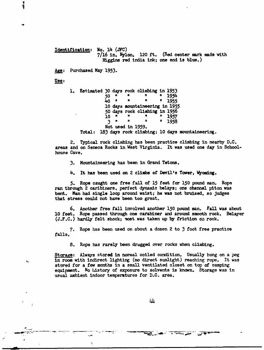
Identification: No. 14 (JFC)7/16 in. Nylon. 120 ft. (Red center mark made with
Higgins red india ink; one end is blue.)
Age: Purchased May 1953.
Use:,
1. Estimated 30 days rock climbing in 195350 " " " 19540 N " U " 195510 days mountaineering in 195550 days rock climbing in 195610 " " " 1957
3 " " " 1958Not used in 1959.
Total: 183 days rock climbing; 10 days mountaineering.
2. Typical rock climbing has been practice climbing in nearby D.C.areas and on Seneca Rocks in West Virginia. It was used one day in School-house Cave.
3. Mountaineering has been in Grand Tetons.
4. It has been used on 2 climbs of Devil's Tower, Wyoming.
5. Rope caught one free fall of 15 feet for 150 pound man. Roperan through 2 caribiners, perfect dynamic belays; one channel piton wasbent. Man had single loop around waist; he was not bruised, so judgesthat stress could not have been too great.
6. Another free fall involved another 150 pound man. Fall was about10 feet. Rope passed through one carabiner and around smooth rock. Belayer(J.F.C.) hardly felt shock; most was taken up by friction on rock.
7. Rope has been used on about a dozen 2 to 3 foot free practicefalls.
8. Rope has rarely been dragged over rocks when climbing.
Storage: Always stored in normal coiled condition. Usually hung on a pegin room with indirect lighting (no direct sunlight) reaching rope. It wasstored for a few months in a small ventilated closet on top of campingequipment. No listory of exposure to solvents is known. Storage was inusual ambient indoor temperatures for D.C. area.
\-7

Identification: No. 15 (EL-i)7/16 in. Nylon. 120 ft.
A•: 10 years
Use:
1. Used for climbing each year in 19 year life.
2. Climbing has been mainly on rock in Tetons, but also some snowand glacier work.
3. It has become water soaked marq times but "seems to retain itssupple characteristics."
4. Never subjected to arn %axcessive strain, such as in free falls.
5. Used extensively for rappelling, doubled, through carabiner.
Storage:
Practically always stored in dark and dry places between periods ofuse.
Identification: No. 16 (BA-2)
7/16 in. Nylon. 120 ft.
Am: 13 years.
Use and Storage:
1. Rope was used in climbing for first 7 years.
2. "Since then, it has been used inside of a large haq barn, tohold the heavy hay door up in place. For that reason, it has been undertension over about 75 ft. of its length for the past 6 years, -- stretchedwith no support from beneath. In this spot, it has received considerablemoisture from exhaled vapor from cattle below during winters -- has beendry during summers".
NOTE: This could be in interesting specimen. In an eulier letter,Mr. Adams estimates there whs about 500 pounds tension on rope. (AEP)
45Ap
'Z7

iftntification: No. 17 (ACL)7/16 in. Nylon. 120 ft.
Purchased Dec. 1950 from Plymouth Cordage.
Use:
1. Weekend rock ciiLmbing use: "It was used about 3 times a monthin 1951 on Sunday or weekend practice climbs on schist or quartzite inD.C. area. From 1952-54, it was used about once a month on weekend prac-tice climbs, usually on Sierra granite or in Southern California practicearea3, seasonrlly on Sierra snow. From 1955-58, it was used about once amonth on D.C. practice climbs".
2. Expedition type climbs:
1951 - Devil's Tower, Wyo. Sustained one 20 ft. free fall.1952 - Canadian Rockies, Assiniboine Area, mostly on snow.1953 - Waddington area (Coast Range, British Columbia). mostly on snow.1954 - None.1955 - Mt. W•,tney, California, area, mostly on rock.1956 - None.1957 - None.1958 - Colorado Front Range and Boulder, Colo., area. three weeks, mostly
on rook•.Schoolhouse Cave, West Virginia, used as a safety rope on three
trip. Wet clay mud and dolomite rock.
Storage:
Storage has been dry, either in attic or utility room. No knownexposure to fumes or solvents.
16
A-- -

t
Identification: No. 18 (EH)
7/16 in. Nylon. 120 ft. ("Plymouth, heat-set nylon")
Age: 6 years.
Use:
1. Where Used: Primarily in New England, New York and Washington,D.C. for rock climbing. Also used on following mountaineering trips: 5climbs in Tetons, 2 cl;.mbs in Canadian Selkirks and on Alaska glaciers.
2. How Used: Rock and snow climbing.
3. Length of Use: Almost every weekend for 2 years in Washington,D.C.; other 4 years, 12 to 20 climbing days per year.
4. Rope usually used for safety, rappels and belaying, a littletension climbing, one leader fall.
Storagg: Warm, dry room under cover.
47
~ - - ~ 4A

Identification: No. 19 (AJK)
7/16 in. OD Nylon. 120 ft.
Ae: New in 1946.
Use:
1. In 1946 it was used on a mountain climbing trip; stretched acrossa river that had to be ferried; it was subjected to very severe strains.(Location of trip not given).
2. It was used on another mountain climbing trip in 1947. This wasin British Columbia and involved rock, snow and Joe,
3. From 1947 to 1951 or 1952 it was used extensively on rock climbsin the Washington, D.C., area.
4. "Rope was more or less retired in 1951 or 1952. Nevertheless, ithas had a great deal of use, and n guess is that one can say it has hadat least six months of wear as a climbing rope." (Quoting from letterfrom Kauffman).
Storage:
Apparently stored in an apartment with camping gear; not kopt onfloor, not subjected to fumes or solvents, and not stored in direct sun-light.
Locale:
Washington, D.C.
48
*

Apnendix B

MIL-R-1688B2S UPTZ DES R 1963
M .,--.416M(GL)11 OCOSI3 1962MII.L-a-lm22 NOVKUUUgl 1949
MIUTARY SPECFICATION
ROPE, CLIMBING, NYLON
This specijcation hca been approved by the Department of Defensc and is man-datory for ue by the Departments of the Army, the Navy, and the Air Force.
1. SCOPE (Copies of specificafioa. and standards required by&uppliers in connection with specific procurement func-
1.1 Scope. This specification covers nylon tions should be obtained from the procuring activity or
climbing rope. as directed by the contracting officer.)
1.2 Claussfication. The nylon climbing rope 3. REQUIREMENTSshall be fmrnished in one type in the sizes speci- 3.1 Preproduction sample approval. Whenfled (see 6.1). specified, before production is commenced, the
2. APPLICABLE DOCUMENTS supplier shall submit an 80 foot sample of the
rope which he proposes to furnish to the contract-2.1 The following documents of the issue in ing officer for approval.
effect on date of invitation for bids or request for 3.2 The requirements specified in 3.7, 3.9 andproposal, form a part of this specification to the 3.10 apply only to rope purchased directly by theextent specified herein: Government. All other requirements apply to
SPECIFICATIONS rope purchased as a component for an end itemby a supplier, and to rope purchased directly by
FXDZRAL the Government.
CCC-T-191 - Textile Test Methods. 3.3 Standard sample. The rope shall match
MILITARY the standard for shade and shall be equal to orbetter than the standard sample with respect to
MIL-C--3131 - Cordage; Preparb.tion for all characteristics for which the standard is ref-Delivery of. erenced (see 6.2).
STANDARDS 3.4 Materials. The rope shall be fabricatedfrom bright, virgin, continuous-filament nylon
1MIJJTAE fiber. The nylon shall be long chain polymer
MIL-STD-105 - Sampling Procedures and made of hexamethylene diamine and adipic acidTables for Inspection or a long chain polymer of epsilon amino caproicby Attributes. acid (see 4.2.5).
50
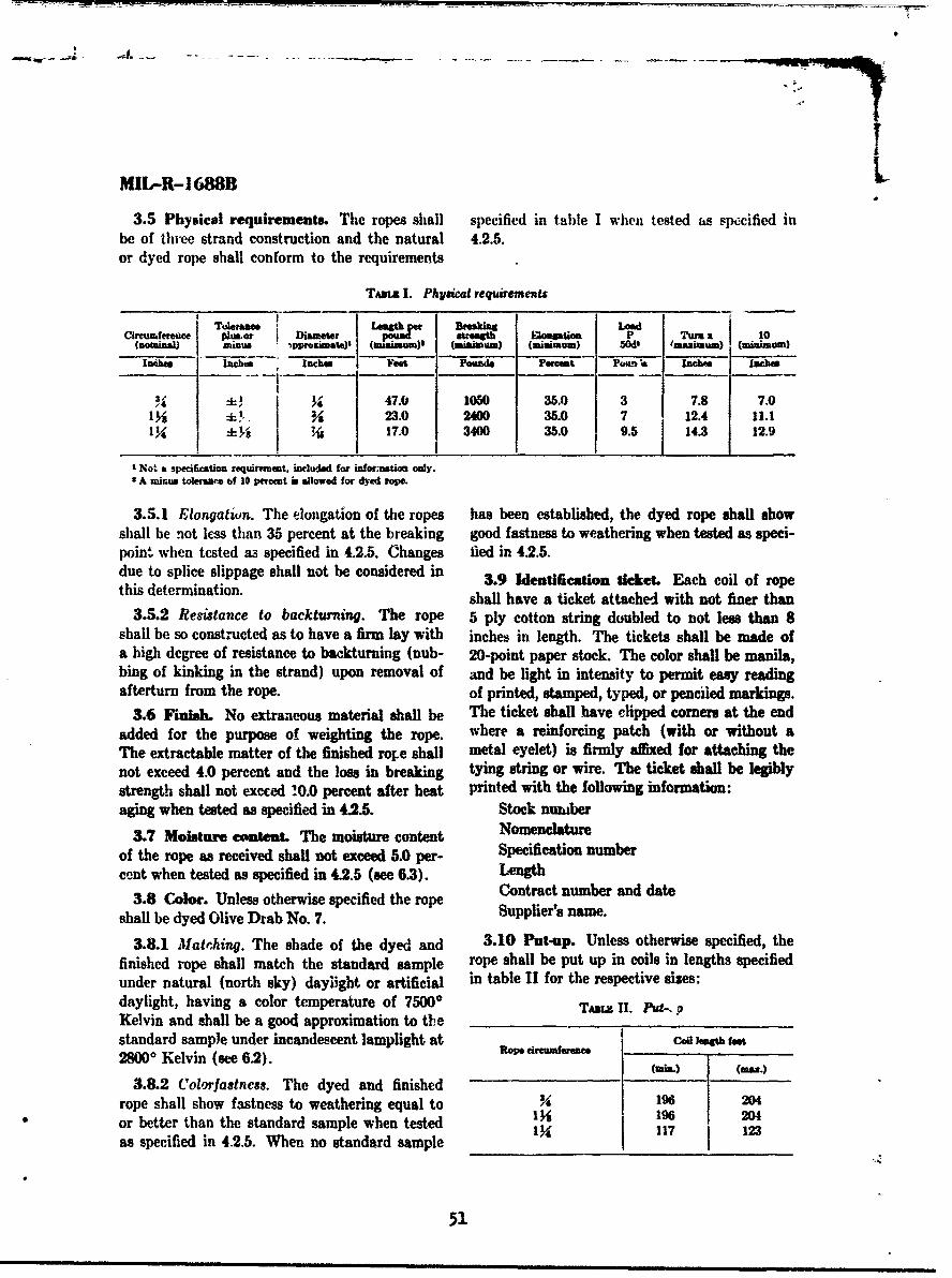
IMIL-R-1688B
3.5 Physical requirements. The ropes shall specified in table I when tested as specified inbe of three strand construction and the natural 4.2.5.or dyed rope shall conform to the requirements
TAso I. Physical requirements
Circumfereoce olusor Diameter Tua P a 10(nouminal) minus 'pprimatm) u (mmum) (imimum) 50W' 'mamum) (minum)
IftM lnch,* "cho FVat Pounds Permt P01m ,a Inchea Inciw
3+ j 3• 47.0 1050 35.0 3 7.8 7.01, 23.0 2400 35.0 7 12.4 11.1
1 -4 17.0 3400 35.0 9.5 14.3 12.9
SNot a specificatiom requirfemt, induded for i.____ ___ only.2 A suuua tolerance of 10 percmt is allowed for dyed ro.
3.5.1 Elongatiun. The dongation of the ropes has been established, the dyed rope shall showshall be not less than 35 percent at the breaking good fastness to weathering when tested as speci-point when tested as specified in 4.2.5. Changes fled in 42.5.due to splice slippage shall not be considered in 3.9 Identification ticket. Each coil of ropethis determination. shall have a ticket attached with not finer than
3.5.2 Resistance to backturning. The rope 5 ply cotton string doubled to not less than 8shall be so constructed as to have a firm lay with inches in length. The tickets shall be made ofa high degree of resistance to backturning (Dub- 20-point paper stock. The color shall be manila,bing of kinking in the strand) upon removal of and be light in intensity to permit easy readingafterturn from the rope. of printed, stamped, typed, or penciled markings.
3.6 Finmsh. No extraneous material shall be The ticket shall have clipped comers at the endadded for the purpose of weighting the rope. where a reinforcing patch (with or without aThe extractable matter of the finished role shall metal eyelet) is firmly affied for attaching thenot exceed 4.0 percent and the loss in breaking tying string or wire. The ticket shall be legiblystrength shall not excced !0.0 percent after heat printed with the following information:aging when tested as specified in 4.2.5. Stock nuaber
3.7 Moisture entent. The moisture content Nomenclature
of the rope as received shall not exceed 5.0 per- Specification number
cent when tested as specified in 4.2.5 (see 6.3). LengthContract number and date
3.8 Color. Unless otherwise specified the rope Supir's name.
shall be dyed Olive Drab No. 7. Suppliers name.
3.8.1 Matinhing. The shade of the dyed and 3.10 Put-up. Unless otherwise specified, thefinished rope shall match the standard sample rope shall be put up in coils in lengths specifiedunder natural (north sky) daylight or artificial in table 11 for the respective sizes:daylight, having a color temperature of 75000 TADL, II. Put-. '-Kelvin and shall be a good approximation to thestandard sample under incandescent lamplight at Codlowth feat28000 Kelvin (see 62). ()a.Wmi.) m.
3.8.2 Colorfastness. The dyed and finished
rope shall show fastness to weathering equal to Y 196 W4
or better than the standard sample when tested 1% 196 203
as specified in 4.2.5. When no standard sample I X_117_123
51

a%
MEL-R-1688B
Thie rope, put up in coils as specified in table 11, accordance with 3.1, shall be visually inspectedshall hT in one continuous piece and so wound for appearance, color and finish. The samplethat each turn and layer is free from entangle- shall be tested for physical and chemical charac-
Ai ment. The ends of all rope shall be cut off teristics in accordance with 4.2.5, to the extentsquarely and securely whipped or heat sealed to applicable.prevent fraying or untwisting. 4.2 Inspection. Sampling and inspection shall
3.11 Workmanship. The finished rope shall be performed in accordance with Standard MIL-be clean, free from objectionable odor, and shall STD-105, except where otherwise indicated.conform to the quality and grade of product 4.2.1 Inspection of components. Qualit) ;s-established by this specification. The occurrence surance provisions for components described sli.of defects shall not exceed the applicable accept- be in accordance with subcoidiary specificatbdio
able quality levels established by this specifica- and dr dawings r wuferenced to the extent cpplicalie
tion.andrwnsr!eecdtthexetapiblexcept that this specification shall govern in the
4. QUALITY ASSURANCE PROVISIONS event of conflict.
4.1 Responsibility for inspection. Unless 4.2.2 Examnination of the end item for visual4.1 esposiblityforinspctin. Ul~s defects. Defects found during this examination
otherwise specified in the contract or purehase dfcs eet on uigti xmntoorderthe supepiier is tresponsilt t for purhae pershall be classified in accordance with the defectsorder the supplier is responsible for the pertf.lin- listed below and regardless of their proximity to
ance of all inspection requirements as specifiedherein. Except as otherwise specified, the .,up- each other, except where two or more defects rep-herein. Exclzept is otherwise spcifitied, te a o- resent a single local condition, in which case onlyp~lier may utilize his own facilities or any corn- the n-ore serious defect shall be counted. The
mercial laboratory acceptable to the Government. samplre fori ths exmai shall be one
The Government reserves the right to perform sample unit for this examination shall be oneanyof he nspctins e,'forh i th spcifca- coil. The lot size for this examination shall bc-
any of the inspections sa' forth in the specifica- expressed in units of coils of the specified sizetion where such inspections are deemed necessary and length of rope. The acceptable quality levelto ascure supplies and services conform to pre- shall be 1.5 major defects anrd 4.0 total defects
i r(major -.nd minor combined) per 100 units. The4.1.1 Preproduction sample inspection. When inspection level shall be Level III of Standard
required, the preprod-tction sample submitted in MIL-STD-105.
Visual examination-defects
ClassificationExamine Defect
SCritical- Main, Minor
Appearance and Cut, any ............................... Xworkmanship.
Chafed or damaged ....................... .. XKinks, darting yarns1 broken or loose ends, bulged
strands . . . . .... ...... ... .......... XKnots, splice, searing, rneling or fusing together of ends
to make a continuous length ..................... XColor. ... . Other than specified ........................ ...... X
Not uniform ................... ........................ xCleanness. ........ Spot or stain, clearly visible2 . . . . . . . . . . . . . .. . . . . . . . . . . . . . . . . . X
Objectionable odor ............................................... XIdentification ticket. Omitted, incorrect, illegible, innecurely attached .............. ............ XBackturning ........... Evidence of nubbing or kinking on removal of afterturn. .......... X
1 Darting yam are internal yarns which project thromgh the cover yam of the strand at intervals alone the rope.
' At normnal inapretion distance (approximately 3 feet).*Vote. On hundred p-escet (100%) inspection shll be performed for critical defects on each lot found acceptable under the sampling and
inspection for majos and total defects. Any length of rope found to contain a ertical defect shall be rejected and returned to the supplier.
52

MIL-R-I6a8B
4.2.3 Examination for length and winding. ance with list below. The sample unit shall beThe sample unit for this examination shall be one one shipping container fully prepared for deliverycoil. The inspectiou level shall be level L-6 and with the exception that it need not be sealed.the acceptable quality level shall be 4.0 percent Defects of closure listed below shall be examineddefective. For lots consisting of 500 or fewer on shipping containers fully prepared for de-
units, the eample size shall be 10 and the accept- livery. The tot size shall be the number of ahip-able number I. The lot .,,ie shall be the number ping containers in the end item in-pection lot.of units in the inspection !ot. Defects shall be as The inspection level shall be L-I and the AQLlisted in 4.2.3.1 and 4 2.3.2 below, shall be 4.0 defects per hundred units.
4.2.3.1 Defects i'.th regard to length shall be site Delect
considered to exist if any o! the following are Marking Omitted, incorrect, illegible, of improperdetermined during inspection: (exterior size, location, sequence, or method ofdetemind dringinsecton:and interior), application.
(a) Length of unit less than or more than aterior). compone
length specified. Any component damaged.
(h) Length of unit less than marked on Workmanship .Inadequate application of complmente,ticket. such a: incomplete closure of case
liners, container flaps, loose strapping,4.2.3.2 Defects with regard to winding shall inadequate staplingl.
be considered to exist if any of the following are Bulin or distortion of containers.
determined during inspection:Packi .... Not as specified.
(a) Improperly or not firmly wound rerult- Coils not secured as specified.ing in kinks, knots, entangling or slip- Packing ...... Not as specified.page during unwinding or otherwise Weight ....... Grow weight exceeds requirementILaffecting free unhampered unwindingof rope. 4.2.5 Testing of the end item. The methods of
(b) Frayed ends not cut off squarely or testing specified in Specification CCC-T-191,
neatly. wherever applicable and as listed in table IVIshall be followed. The physical and chemical
SEnds not securely whipped or hcx. .tlues specified in section 3 apply to the result(s)treated to prevent fraying or untwist- of the determination(s) made on a sample uniting. for test purposes as specified in the applicable
4.2.4 Examination of preparation for delivery test methods. The sample size and acceptancerequirements. An examination shall be made to and rejection number shall be in accordance withdetermine that packaging, packing and marking table MII. The sample unit for testing shall be 80requirements of section 5 of this specification are feet of rope. The lot size shall be expressed incomplied with. Defects shall be scored in accord- units of coils.
TAsz M. Sampig for testa
hAmeeptane ber for 4e*etio number s..r eachNumber of soils in lot Number of samples each teat c teristie tet characteristic
15 sand under 2 0 116 to 40 3 0 141 to 110 5 0 1Ill to 300 7 0 1301 to SO 10 0 1501 sand over 15 0 1
55 53 1
mu im m n nn lml| m m s nmram •lll • um ~l! •nI

BIL-R-1688B
TAwx IV. Teat method.'
Number of
reeCharcten tic Test meLo4 per Individual Resulta reported a&-eamIo unit
Materia.................. 3.4 I•tsad .................... 3.5 Visual I Pass or failCiteumfermce ............. 3.5 4.2.5.1 3 Average of 3 determinations to nearest
% inch.Length per pound .......... 3.5 4.2.5.2 1 Reported to nearest 0.1 foo;Breaking strength
lnito,. . . . . . . . . . . . . . . . . . . 3.5 41063 3 Av-•rage of 3 determinations to nearest10 lbs.
After agint, .............. 3.6 41G6 and 2 Average of 2 determinations to nearest4.2.5.3 10 lbs. calculated to nearest 0.1 per-
cent.Length per turn x 10 ........ 3.5 4.2.5.4 3 Average of 3 determinations to nearest
0.1 inch.Elongation ................ 3.5.1 4106' 3 Average of 3 determinations to nearest
0.1 percent..Finish (weighting) .......... .Extractable matter ......... 3.3 4.2.5.5 2 Average of 2 determinations to nearest
0.1 percent.Moisture content ........... 3.7 2600 2 Average of 2 determinations to nearest
0.1 percent.Colorfastness to ireathering." 38.2 4671k 1 Pass or fail
go see below table.2 Tests to determine complimac with specifcation requiremnta including quatity of delivery may be moads under prevailing atmosphuie
conditions except in settlement of dispute in which cae the tests shall be mado upon material which has reached equilibrium under StandardConditlios s defned in Speciication CCCT-19l.
2PteqUirement accepted on bams of suppliers certification of compliance thereto.
4 Method 4101 shall be followed except that the load "P" shall be as specifed in table I for the respective eisa.I lgation at the breaking point may be del.ermined autographically.
* Unless otherwise specified, the apparatus shall be as specified in method Mt. except that:(a) Delete from title "(National Weathering Unit)."(b) The specimens Al be exposed for forty standad hours.(e) The filtars shall not be removed when tinting.(d) Water-spray nozzle shall be mounted horisontally (the water-spray assembly vertically) in the test chamber inside the spechim rack
and so placed that the water shall strike the specimens evenly over their entire length in the form of a ine spray in sufficientvolume to cover specimens iinmediately on impact. The apparatus shall be so operated that the specimena ame exposed to sucesmivecycles of 102 minute of light without spray and 13 mainute of light with spray.
(W) The rack shall rotate about the arc at a uniform speed of an revolution per minute.(f) The pressre of the water entering the spray shall be 12-18 pa.i. inclusive.(g) The black panel thermometer shall be mounted en the teat panel rack and reedings taken at a point whore maximum heat is devl-
oped and where water spray is not striking the panel. The black panel temperature at the exposure plane of the specimen rackshall be I5* plus or minus 10' F., %hen the filters are in place and 175" plus or minus 10" F. when the filters are removed.
(h) Attention is called to manufacturers who own equipment which operates at one cycle in two hours. This equipment may continueto be used. However, the one cycle per minute shall be the staudard procedure in the event of dispute
4.2.5.1 Determi. !i-nt of circumference. The than two turns of rope apart. The average ofcircumference shall be measured with the speci- these determinations shall be the circumferencemen under the load "P" specified in table I for of the rope.the respective size. With the specimen under thisload a fiber shall be passed snugly around the 4.2.5.2 Determination of length per pound.rope and cut where it overlaps. The cut length A minimum of 12 feet of rope shall be subjectedshall be straightened and measured to the nearest to the load "P" specified in table I for the respec-h inch. This determination shall be repeated at tive size. While under this tension a distance ofleast three times in different positions not le.s twelve feet shall be accurately measured, 1,1t out
54

MIL-R-168BB
of tih speciiuen and accurately weighed to within 5. PREPARATION FOR DELIVERYp!us or minus 0.5 percent of its total weight. Thelength per pound shall then be calculated untiliz- 5.1 Packaging. Packaging shall be level A oring the 12 foot measurement obtained under load. C as specified (see 6.1).
4.2.5.3 Breaking strength after heat aging. 5.1.1 Levels A and C. The rope put up as
Two breaking strength specimens prepared as specified, shall be packaged n accordance withspecified in Method 4106 shall be heated for 5 the applicable requirements of Specification
days in a convection air oven at 175 4 ± 20 F. MIL-C-3131.After aging, the specimens shall be allowed toreach equilibrium under Standard Conditions 5 acking Pk ing sl L l Bbefore being tested for strength. The percentchange in strength shall be calculated based on 5.2.1 Levels A, B or C. The rope shall bethe average strengths iritially and after heat packed in accordance with the applicable re-aging. Breaking strength shall be calculated in quirements of Specification MIL-C-3131.accordance with Method 4106.
5-3 Marking. In addition to any special4.2.5.4 Determination of turn. Determina- marking required by the contract or order, ship-
tion of turn shall be made by taking a straight ments shall be marked in acocrdance with Speci-length of the sample rope and measuring the fleafion MIL-C-3131.length parallel to the axis of the rope of tencomplete spirals of one strand. The turn is one-tenth of this measurement, but for conveniencethe requirement of table I is for ten times the 6.1 Ordering data. Procurement documentstU2rn. •should specify the following:
4.2.5.5 Determination of extractable matter. (a) Title, number and date of this specifi-A sample of rope weighing approximately 5 grams cation.shall be placed in a tared weighing bottle and (b) Put-up, if other than sjpec't .1 (seedried to constant weight at 1050-1100 C. After 3.10).the bone dry weight has been determined, tnespecimen shall be transferred to a soxhlet extrac- (c) Selection of applicable levels of packag-tion apparatus for a minimum of twenty extrae- ing and packing (see 5.1 and 5.2).tions, using reagent grade petroleum ethei (boil- (d) Size required (see 1.2).ing point range 300 to 650 C.) as the solvent.The petroleum ether shall then be evaporated ( ui When diie preproduction sample is re-from the extract in the tared flask at a tempera- quired (see 3.1).tore of 1050 ± 50 C. to constant weight, cooled 6.2 Standard sample. For access to thein a desiccator and weighed. This is the "weight standard sample, address the procuring officeof extractable matter." The percent extractablematter present is c-leulated from the following is.uing the invitation for bids.formula: 6.3 Adjustment for high moisture content.
Percent extractable matter -Material furnished containing an excess of mois-Weight of extractable matter X 100 ture will be accepted by an adjustment in weight
Weight of dry specimen to the 5 percent moisture content.
Military usodianm: Preparing aeaty:Army--GL Army--GLNavy-MC Projec No. 4020.-0029Air For OA-MOA
6U, . O(VesRNMSII PRINTING OFPIC!.t 19I
55

APPENDIX C
V ROPE HARDNESS TESTING;t. SUIARY OF OBSERVATIONS
by
L. J. Sheehan, Textile TechnologistBoston Naval Shipyard
"Test No. 13117A
25 May 1959
Reviewed by Approwvct by
R. T. Sadler, Jr. M. B. GrahamSupvy. Materials Egineer Hrad, Laboratory Branch
,.7

MOA1NDUM REMU~
Test No: 1311?A
Subject: Rope hardness testing; sumary of observations
Reference: (a) BUSHIPS Cordage Program, NS-031-003
1. During evaluation of the earISy types of rnlon ropes in connection withreference (a), it was found that certain rope constructions, although flex-ible and spliceable when received, developed excessive hardnrXs in storage.It was observed that the aged ropes could not be satisfactorily knotted,spliced, or bent on holding devices owing to stiffness. Service trials withthese ropes proved unsuccessful, primarily because of these difficulties.
2. Study of the rope constructions employed in the unsatisfactory ropesshowed that, 2n general, three basic high-twist yarn systems were used,name•y: (I) groups of one size of large singles yarn; (2) groups of largesize uiltiple plied yarns; (3) large multiple plied yarns of varying sizesgrouped with the smaller yarns encasing the large yarns. The strand andrope turns employed varied according to the yarns sizes, but in generalthe turn combinations were des Lgned to yield ropes having high resistanceto back-turn and fore-turn. To further assure attainment of these goalsthe manufacturers had heat-set their products and thus imposed shrinkageto lock the nylon yarns in place. These ropes by virtue of their con-struction were overly hard and difficult to employ aboard ship.
3. With the adoption of balanced plied cord system for manufacture ofnylon ropes it became possible to design nylon ropes with any degree ofsoftness and flexibility, and with no tendency to harden in storage. Inorder to assure procurement of suitable pylon rope having the necessaryhandling qualities, a study was initiated to find a quantitative non-destructible means of differentiating between ropes of good and poorutility from the standpoint of hardness.
4. It was at first believed that flexibility tests might possibly serveto screen out unsuitable rope structurt s. A search of the literature dis-closed that numerous methods have been employed for assessing flexibilityof textile materials. In general only two basic systems were employed,namely, cantilever bend methods and angle of lay measurements. It wasapparent that the latter method would not be applicable to rnlon ropes be-cause of the wide range of angular ratios which cai be employed in manu-facture of ropes using continuous filament elastic fibers. A review ofthe cantilever systems for assessing flexibility disclosed that for eachrange of flexibility the test methods were different, as indicated below!
58
4iZ . . .

FlexibilityMethod of Material
Simple Cantilever Limp
Weighted Cantilever Moderate
Double Cantilever Stiff
Heart Loop Very Limp
Circular Loop Moderate
Pear Loop Soft curly
th Dynamic Cantilever Pendulum Very stiff
For example, with a flexible material a single self-weight cantilever angleof deflection or a heart loop method was used. With harder and less flexiblematerials a weighted cantilever bending length. or circular loop method wasused. With very hard, stiff materials a dymmic weighted swinging pendulummethod was employed. The literature further indicated that the differentmethods could not be Inter-related and that values from one method wouldnot predict the range of values from another method.
5. A comparison of cantilever flexibility values with the practical indiceeof knotability and splceability showed no correlation. Further it was foundthat bending resistance (flexibility) measurements varied widely in islonropes, depending on the method employed. It was concluded that the canti-lever bending methods, although satisfactory for a relative ranking of theflexibility of rylon ropes, could not serve as an index of utility. Theflexibility tests measured the resistance to bending over relatively longlengths of ropes. In contrast, the bending quality indicative of knottingand splicing properties could only be found in short bends.
6. Analysis of the bends in knots and splices indicated that the bendingresistance of the rope strands was the major factor contributing to hardnessand stiffness of nylon ropes. A study of the art of rope splicing pointedto the primary difficulty in hard r'2.on ropes, namely the great effortnecessary to force the strands apart with a marline spike to make room forthe marrying strand. It was also noted that with each additional tuck therequired force increased. In view of this, it was concluded that the re-sistance to strand displacement could be used as an index of hardness andstiffness.
7. It was decided to simulate the opening action of rope splicing bymeasuring the resistance in a compression testing machine. Experimentswere conducted using a 14 inch tapered marline spike inserted between therope strands and forced inuard in a compression testing machine at 6' perminute. Load measurements were taken at each 1/8 inch increment of pene-
£9

4q
tration. The ropes included in the tests were of various constructions andsizes ranging from 1-1/8" to 5 1/2" circumferences. The strand constructionswere coded alphabetically and typed numerically, as follows, for easyidentification:
SDsc ri tion
1 Strands formed with balanced plied yarns and layed into ropesas described in MIL-R-1734A, of 15 October 1957.
2 Strands formed with large multi-plied yarns encased by smallermulti-plied yarns layed into ropes and heated to set the lay.
3 Strands formed with high twist large singles yarns layed intoropes and heated to set the lay.
4 Strands formed with large low twist core yarns encased bysmaller high twist multiple plied yarns, layed up tightly intoropes.
8. The results of the tests are plotted in Figures 1 and 2, It maybe noted that with small nylon ropes there was a deflection in slope of theresistance curves at strand openings of 1/2" to 5/8". A similar deflectioncan be noted in the curves of large nylon ropes between 7/8" and 1" strandopenings. It was observed that flattening occurred in the rope strands atthese opanings. Beyond these openings the rope became stranded as onestrand pulled tight against the other two strands in portions adjacent tothe site of opening. With hard ropes the strands became permanently dis-torted at the indicated opening. With softer ropes no permanent distor-tion occurred at any strand opening.
9. For inspection purposes it -as decided that the test should measure theresistance at an opening of 1/2" for small ropes, and 1" for large ropes.A limiting value would apply in each case. Also, it was decided that thewet hardness should be measured. Wetting of nylon rope hastens relaxationshrinkage and thereby causes the fibers to compact in the rope structure.Hardening and stiffneing observed in stored ropes resulted from the samephenomenon, induced by changes in humidity during storage. In order topreclude hardening in storage, it was ;.pparent that a limit should be placedon the wet hardness of new nylon ropes, as well as on the dry hardness.
10. On the basis of the tests, the following method is recommended as aninspection procedure for evaluating the hardness quality of nylon ropes:
"A length of nylon rope shall be secured at each end to prevent un-laying. A 14 inch marline spike, conforming to type I of Specification4IL-M-15926, shall be inserted between the strands until visible on theopposite side. The spike shall be inserted at least 5 feet from the endor 5 feet from an area which has been su'bjected to a previous hardnesstest. The rope with the spike insertee. shall be mounted in a compressiontesting machine in such a manner that the force necessary to push the spike
60
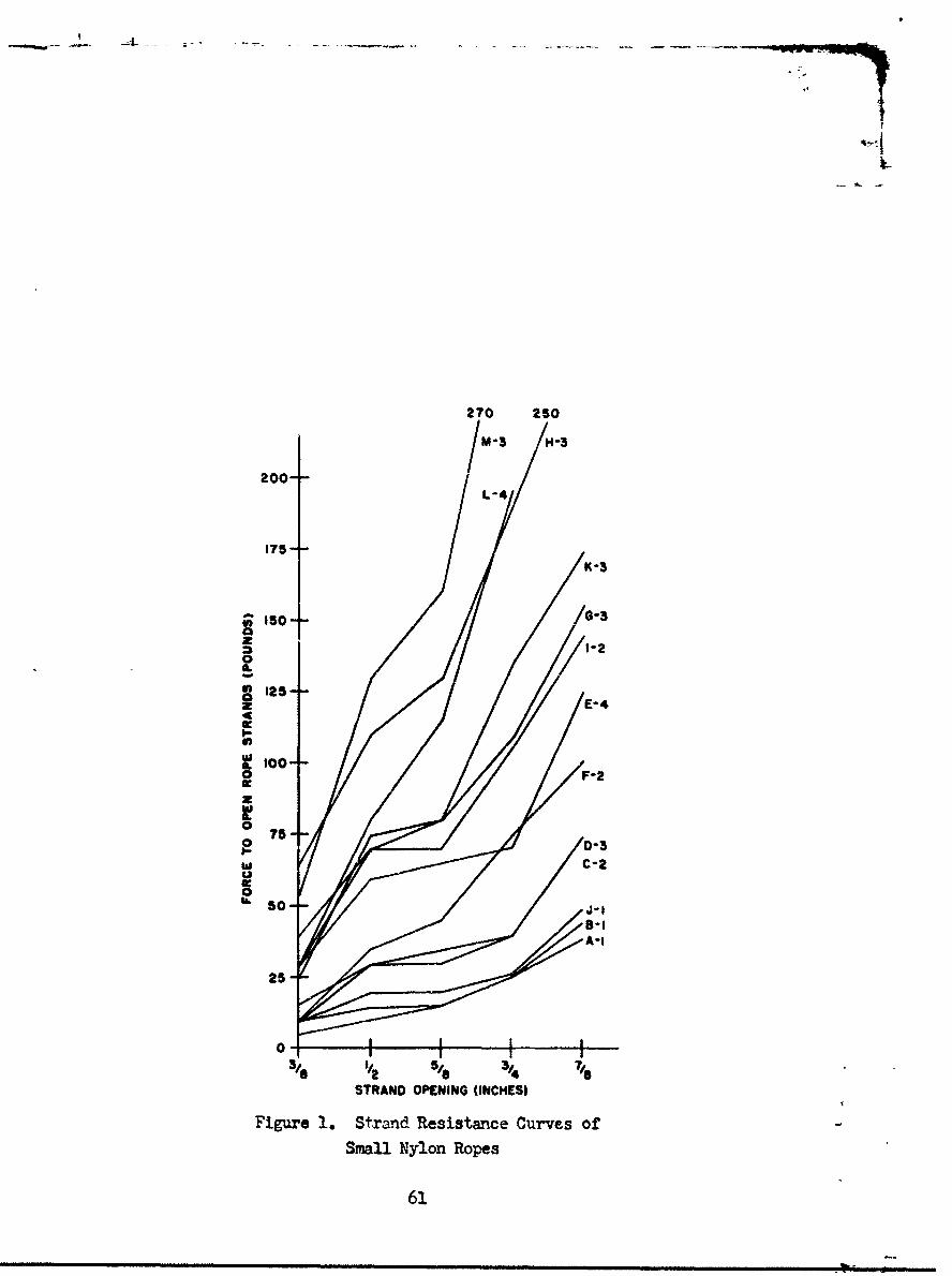
270 250IM-3 /1-3
200-L-4
175-K -3
5so T G-3o 1-20
S125---z E-4
a. I00- F-2
w
075-
-D-3 ° y C-2o 50,- 4 -1
A-i
25-
STRAND OPENING (INCHES)
Figure 1. St~rand Resistance Curves of
Small Nylon Ropes
61
""a r .. .

$40
$00V-
700
o0-3
Soo
4~ 00
0)
30o
0-
200 0-
62.

through the rope can be measured. The rate of loading shall be 6 inchesper minute. The load necessary to force the spike into the rope to the1/2" diameter mark shall be measured on ropes up to 2-3/4" circumference.The 1 inch diameter mark shall be used for larger rnlon ropes. At leastthree test results shall be averaged for reporting the hardness values.
The above tests shall be conducted on the dry rolon rope and after ithas been immersed in tap water at room temperature for 16 hours and drainedfor 2 hours."
l1. Based on experience over the past four years, the following hardnesslimitations are recommended for nylon rope, using the test method de-scribed above:
Size Wet &op
Up to 2-5/4" circ. 5 lbs. 25 lbs.
3" to 10" circ. 20 lbs. 100 lbs.
12. In connection with the subject of hardness testing it may be of in-terest to discuss the various factors which influence rope hardness.Marx factors enter into this property, as follows:
a. Fiber size and shape. Fibers of largest cross-section have thegreatest bending and torsional rigidity to resist deformation. Conse7uentlvropes made of large fibers will exhibit greater hardness and stiffness thanthose made of smaller fibers. The shape of the fiber influences rope hard-ness by frictional effects imposed when contact surfaces are increased.For example, fibers of circular cross-section in contact with each otheroffer less frictional resistance than fibers having a pentagonal cross-section like manila. The irregular fibers will produce a harder rope thanthe circular fibers under the same manufacturing conditions.
b. Fiber finish. Nylon finishes which lubricate the fiber lower thefrictional resistance and impart degrees of freedom for fiber movement,thus lowering the hardness ot the rope structure.
c. Recovery and relaxation shrinkage. The recovery and shrinkageforces of rnlon fibers are relatively high In total amount. Because eachforce develops at a different time, the total effect was not noticed byearly investigators of rolon rope. The recovery from tension and torsiontakes place in two parts, the greater portion being instantaneous and theremainder within 24 hours. The relaxation shrinkage, however, is influencedby time, temperature, and moisture. Its reaction time can vary from a fewminutes to mar•y &onths. The total effect of these two forces in zylon ropeis to compact the fibers as their length is reduced and their diameter in-creased. In ropes having the twist and lay combinations usually employedfor natural fiber ropes, these contracting forces compress fibers togetherand change their shape from circular to polygonal. The fibers in thisstate have little freedom of motion. The rope structure therefore exerts
63

i4
considerable resistance to deformation, and consequently exhibits extremehardness.
d. Yarn construction and twist. High twist singles nylon rope yarnsare unstable when employed directly in strand forming and rope layingoperations. Unbalanced elastic forces cause them to spring apart. Ropesmade of singles yarns will kink, and form strand cockles on handling. Dueto the high recovery characteristics of nylon, the yarn construction shouldbe such that the fiber strains are at the minimum necessary for compactingthe fibers. These strains mst be opposed by a balancing force to preventdisplacement of the fibers in yarn. The balancing forces can only be de-veloped by plying the singles in such a manner that each singles yarn con-tacts the other yarns in the plied structure. This requirement limits thenumber of singles in a ply to two or three. This type yarn structure canbe attained by a variety of twist ratios, but in no instance should thetwists be so high as to place the fibers in a position of high strain.This would cause them to retract and shrink in the rope structure, re-sulting in progressive hardening.
e. Iffect of yarn diameter. The diameter of nylon yarns employedin ropemaking should be as large as possible for better distribution andlowering of stresses from twisting and plying. The yarn size, however,is limited by the rope size desired and the minimum hardness required tocompact the structure. In small rope structures, the yarn size should notbe so large that the strand does not have a central core for positioningthe cover yarns.
f. Effect of yarn position in strands. The position of yarn in thestrand should remain constant throughout the strand length. Should theyarn move from its assigned position, it will crowd between other yarns inperiods along the length. This condition will locally upset the stranddensity, resulting in hard spots which become distorted in service.
g. Effect of strand and rope turn. The strand and rope turn ratioshave the same effect on the rope that singles and ply twists have on pliedyarns. In the rope structure, the plied yarns react in the same manner asindividual fibers in the yarn structure. It is imperative that the turnrelationships be balanced, ard of low magnitude, to offer a twist reservoircapable of absorbing back and fore turns encountered in service. If highturn combinations are employed in strand and rope manufacture, lockedstresses will be impressed in the yarns. Overly hard and unstable ropeswill result.
h. Effect of heatirB on ilon ropes. Nylon fibers possess a relativelyhigh inherent contracting force amounting to 0.4 grams per denier. Thisforce can be released by the action of water and/or heat, resulting inshrinkage in length and swelling in girth. The shrinkage and swelling ofthe fibers amount to approximately 12%. Two-thirds of the shrinkage occursin a relatively short time and the remainder occurs over a long period oftime depending on the amount of compressional forces imparted during ropemanufacture. The total relaxation of the contracting forces can take place
64-

in 24 hours in a soft rope structure, or in marw months in a very hard ropestructurt,. In either case the rope wiAl become more cvmpact. The reasonfor this behavior is that the outer rylon yarns react first and therebycompress the inner fibers. The subsequent shrinking of the inner yarns andfibers is retarded by the compression and concomitant increased frictionaleffects. The available interstitial space has been reduced to a minimum,and there Is insufficient cross-sectional area to accomodate increasedfiber girth. Consequently in these structures the inver fibers assume apolygonal cross-section when they are compressed to occupy the voids.
BIBLIOMPUW
1. Rope Twist and Hardness of Lay, P. 297, The Technolcy of CordageFibers and RSe, Hinmlfarb, D., 1957, Textile Book Publishers Inc.
2. The Measure ,,?t of Stiffnesb in Textiles, Pbbott, N. J., TextileRes. Journ. 21, 435 (1951)
3. "Rope Made from Nylon", British Ropes Ltd., Publication 1948
4. Nylon & Manila Rope Report on Weather and Stowage Tests, U. S. CoastGuard Test and Development Div. Report No. COTD-49-08-27 (1950)
5. A Comparison of Certain Methods of Measuring Stiffness in Fabrics,Winn, L. J., and Schwartz, E. R., Amer. Dyestuff Reports 29, P. 469(1940)
6. Elastic and Crgpp Properties of Filamentous Materials and Other HighPolymers, Leaderman, H., Textile Foundation (1943)
7. Nylon Rope Specification Development, Boston Naval Shipyard MaterialsLab. Report No. 13177, Sheehan, L. J. March 1955.
65

IDETIFICATICU OF SMALL NYLON ROPES
ope Codeand Circumference Age
Type (inches) (months)
A-I 1-1/2" 2B-1 1-1/2" 24c-2 1-1/8" 18D-3 1-1/8" 18E-4 1-1/8" 18F-2 2-1/8" 18G-3 18
H-3 2-1/"181-2 2-1/2" 18J-1 2-1/2" 36K-3 2-1/2" 18L-4 1-3/4" 18M-ý 1-3/41" 18
I=TIFICATION OF LARGE NYLCO ROPES
Rope Codeand Circumference Age
Tp (inches) (months)
N-1 3 10-3 3 18P-2 3 18Q-4 3 18R-2 3-3/4" 18S-3 3-3/4" 18T-3 4-1/2" 18u-1 4-1/2" 1V-3 5-1/2" 18W-i 5-1/2" 1
66

for
Coofficict of Comvlatiogi
67

AMUE-CM 17 August J964
MOAW.U FOR RECaRD
SUBJECT: Coefficient of Correlation Computer Program - C-003
1. TIO
The computer program sumrised In this report was written to computestandard deviations, variarces, and the coefficient of correlation for twosets of variables. The program is limited to 100 values for each of thetwo variables.
2. PROGUM MLMtPTI0NM
The program finds the variances (s2), standard deviatcp (S), andcorrelation coefficient (r) through solution of the following equations:
(1) K• -_
(2a) 2- L A L2- (F.9
N Xr(3) S -- ;
,S L(4) IN __ _ __ _
The valu, of 1 can be no greater than 100. Whenever N is less than40. the variaxes are computed by Equations (2a); otherwise, Equations (2b)are used. The program reads N and the data and computes the correlation;then it airouatica-ly goes on to the next data card to read N and thecorresponding data. The process continues until an MW card appears inthe data to halt the program.
3.1 Deck Mike-UW
The program is written In 12. The obJeot program followed byto deck of data cards is placed behind WIZPAC, and a nwinl WIZ load isexecuted. The answers should follow.
3.2 TM Drives
Not applicable
68

3.3 laThe number of inpt cards is determined by the amount of data
available. The first data card contains oer value for N, the nuaber ofvalues for each of the two variables. This card is followed ba card(s)containing the data in the following order: yxl u. . y29 13. y3
xn, y. Itis imperative that the number of indivtlual readingsf is equal to 2N.
If it is desired to compute mre than one correlation, the dcard contain•iM yn is followed by another card containing the value N fothe second correlation, which is followed by the data as described in theprevious paragraph.
The last card cn ainn Yn iust be followed by an O1MO card.
The values of N and the input data must follwo the rules forWIZ data cards.
3.4 Data Displa
The output consists of a series of tables,, unally on aim page*In the first column are a IS of alue followed by$ X(J); tb In alist of the values for the variable X. Th list of value fer the variabler is similarly placed in the second coluim The tbird oolu• 'cofainsthe value of J for each row. Following these. tab]Le on. the 9 sucednlines are the value forJ,* .1Y, ,y% E 09 Ly') .r S(a drespectitvely. The last line* contains s,, Sy a nd *' A tn!ical output forthis program is attached.
4. VARI ,DCr
NJ19.SMJN
it AVZ
y=AVX4E~t). I SQUARE,f(~m SQUARE-s'. VARI
X AI
S.X a SXS1. sea
'rR
69

1.9000000+01 $ x(J) 9.5000000+o0 $ 1(J) -1 $ -J4.3000000+01 $ x(J) 2.2500000+01 $ Y(J) -2$ -J7.o000000+00 $ 1(J) 1.1000000+01 $ 1(J) -3$ -J8.ooooo0+000 , (J) 1.2000000+01 $ Y(J) .4 * .J3.00000001 . (j) 1.3500000+01 o()$2.1500000+01 X(J) 2.3000000+01 *(J) .6 $ -J6.2000000.01 $ X(J) 3.2000000+01 o (J) -7$ -J2.5000000+01 $ z(J) 1.9500000+01 *(J) -8, -J4.9500000+01 $ X(J) 1.0500000+ , $ 1(J) -9* -J2.1000000+01 $ X(J) 1.2500000+01 $ 1(J) -10$ -J8.1500000+01 $ X(J) 3.9500000+01 $ 1(J) -11 $.4.9000000+01 $ X(J) 1.9500000+01 $ 1(J) -12 $ -J2.90oooo+01 $ x(J) 2.4000000+01 $ 1(J) -13 $ -J1.8000000+01 $ X(J) 1.2500000+01 $ Y(J) -14 $ -J3.8500000+01 $ X(J) 1.5000000+01 $ 1(J) -15 $ -J4.6500000+01 $ x(J) 3.0000000+01 $ 1(J) -16 $ -a3.4000000+01 $ 1(J) 2.8000000+01 $ 1(J) -17 $ -J2.4500000+o1 $ x(j) 1.8oooooo9o+ $ *(J) -1L8 $ -J6.o7ooo0o+o2 $ sU3.372222201 $ AVI3.535000+0o2 $ Stm1196; W8.0 $ OrI2.66o4500+04 $ = =A8.186V499403 $ SQUMBR3.6383006+02 $ V•X7.31707416+01 $ VAR1.3960000+04 $ a~omr1.9(/4330+01 $ S 8.5539900+00 sY 6.9433348-o $ R
70

Utiisaionof the FIaher "ZO
fransformation fcr CogawIM the
Sigrificance ot -Or* Vgxn
71

U. S. ARMI NATICK LABaR.ATM!WREPOT NO:
NATICK, MASSACHUSETTS 8270INJIATED:
MATERIAL EXAMINATION REPOT November 1965REPORTED:December 1963
TITLE: SURUITTED TO:SS. J.K
Utilization of the Fisher "z" transformation PREPARED BY:technique for comparing the significance of "r" mr. L. I. Weinervalues. COPIES TO:
Mr. C. J. Pope
INTRODUCTION: Lt. J. Johnston
In connection with a study of the correlation oflaboratory abrasion testers (1) an analysis was madeusing the Fisher z-transformation to determine the significance of thedifferences between correlation coefficients (Or") of 0.7 and 0.8; 0.7and 0.9; and 0.8 and 0.9. The original study was made on 15 fabricsciiffering in fiber composition, weave type, and weight and iltilized thecommon abrasion instruments employed in the Army Natick Laboratories.Correlation coefficients were computed from a program established for the0E 225 computer. Subsequently regression equations were computed and itwas desired to establish the relatit i significance of the equations interms of the significance of the Or" values.
PROCEDURE:
Values of "f" and the standard deviation of Oz" (U-z) were computedas suggested by Mode (2) according to the following equations:
Z .log~e + r1- r
and z= 1N- 3
The "z" values corresponding to each of the two "r* values being com-pared can be computed from:
l÷r 1zt = 1.15129 logl 0 -+
1-'r1
or obtained fremm a table of values of "z" (2).
72

L
Since the distribution of "z" is approximately normal, we let
#=1- -2
which gives the numb :r of standlard deviatxons separating the two r values.
Thus:
Z(o.8- 0.7) = -- .8 .8.288
z(o.9- 0.7) = - .. 1.288
Z(o.9- 0.8 = 1&47 - 1.095 = 1.3.288
The value of .8 sigma is consistent with the hympothesis that an "r"of 0.8 is not significantly different from an "r" of 0.7.
On the basis "r" values of 0.7 and above were considered of sufficientsignificance to warrant the r-e of computed regression equations.
Detailed computations are shown an the attached table.
REFcqb sC
(1) "Correlation and Regression Analysis of Labcratory Abrasion Testers".MM No. 8267. October 1963.
(2) Mode, E. B., "Elements of Statistics", Prentice - Hall, 1951.
73
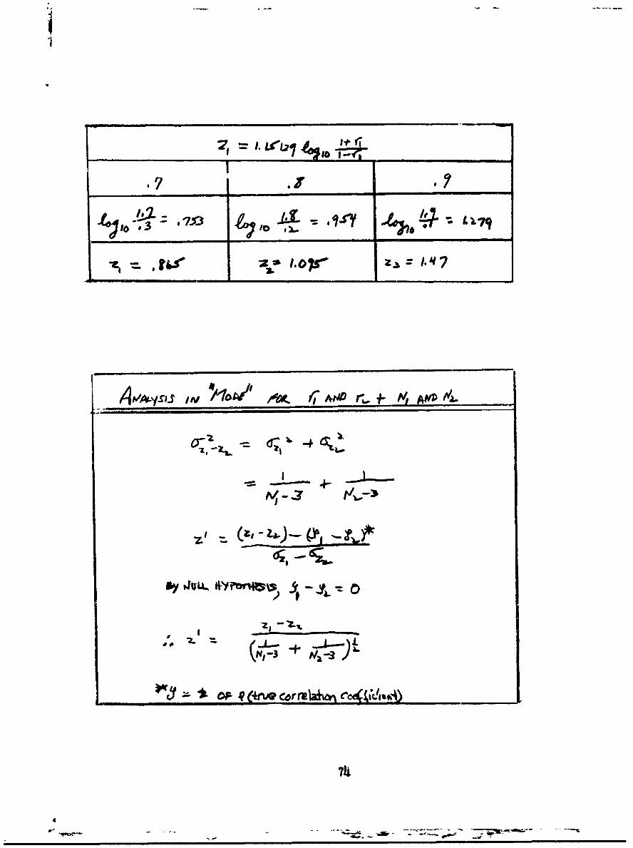
II
FI
'7 .1 ___________
4 .� eo5y
*Z� f"
,d�( f7 AtIl� ,t 1- P'1 ANZ� #�.
- I �
I � %4j�z ________
0. �
) 9
d.
�*O�,vQc�rr� c
7IJ.
-. - - � -� - - -c------ - -��:.-
- -,--- �

Security Classification C R&I%/•.,UM ulI I .JI KUL DATIA. " '[1.
(Security cleeaification of title, body of abetract end Indexini annotation muet be entered wheat. the overal! report to classlfied)
I ,ORIGINATIN G ACTIVITY (Copora.te author) 2a R"- T SECURITY C LA..IFICATION
U.S.Army Natick Laboratories UnclassifiedNatick 2b GROUP
Massachusetts 017603. IIEPORT TITLE
EXTaT AND CAUSE OF DETMRIORATION OF NYLON MOUNTAIN CLIU4BING ROPE
4 DESCRIPTIVE NOTES (Type of report and Inclueive date&)
June 1963 to July 1965s AUTHOR(S) (aet name. firet nam'e, initial)
Weiner, Louis I. and Sheehan, Leo J.
* REPORT DATE 7, TOTA NO OF "AG., ?b No omtre
March 1966 74I& CONTRACT OR GRANT NO. 90 ORIGINATORIS REPCRT NUMBER(S)
b. PROJECT NO. '66-2.4-C1=44sJ01A113
c 9b. OTHERR PORT NO(S) (Any othernumbr., that.may be ea..i,,i
d rS-135
10 A V A IL ABILITY/LIMITATION NOTICES
Distribution of this document is unlimited.Release to CFSTI is authorized.
11 SUPPLEMENTARY NOTES 12 SPONSORING MILITARY ACTIVITY
Clothing and Organic Materials DivisionU.S.Army Natick LaboratoriesNatick, M-assachusetts 01762
I$ ABSTRACT
An analysis was made of 20 nylon mountain climbing ropes which had been inuse for periods up to 18 years, to discover the extent and cause of deteriorationin strength and energy-absorbing ability and changes in hardness and stiffness.It was found that 13ss in st .,ength and energy-absorbing ability arise primar-lyfrom fiber abrasioL. which occurs at the surface of the rope. The nature of therope construction is such that surface abrasion affects each of the three strancsof the rope and all of the yarns in each strand except the few which constitutethe so called "inner-core."1 There is no evidence that sunlight damage occurredto any significant extent in these ropes. The amount of abrasion and loss ofstrength were directly related to the amount cf use (not age) for those ropes thathad more quantitative use histories. A Use Index (computed from the number of daysof use) may be used to estimate rope deterioration. The extent of hardening andstiffening of the ropes was found to vary over a wide spectrum, but the causalfactors were not determined.
DD I,.. 6. 1473 Unclassified_Security Classification

IIUncl a ified
Security Clisifiic,,tion
KEY WOROS LINK A LIK0 4 LINK C ]__WT ROLE WT ROLTW I -oL T7~
Deterioration 89Rope 9 9Nylon 9 9Mountains 9 4Climbing 9Analysis (Structural)
Abrasion 10Surfaces 10Fiber 10
- I -
INSTRUCTIONS
1. ORIGINATING ACTIVITY: Enter the name and address 10. AVAILAB!LITY/LIMITATION NOTICES: Enter any lim-of the co. tractor, subcontractor, grantee, Department of De- itations on further dissemination of the report. other than thosefense activity or other organization (corporate author) ,ssung imposed by security classification, using standard statementsthe report. such as:2a. REPORT SECURITY CLASSIFICATION: Enter the over- (1) "Qualified requesters may obtain copies of thisall security classification of the report. Indicate whether"Restricted Data" is included. Marking is to be in accord- report from DDC."ance with appropriate security regulations. (2) "Foreign announcement and dissemination of this2b: GROUP: Automatic downgrading is specified in DoD Di- report by DDC is not authorized."rective 5200. 10 and Armed Forces Industrial Manual. Enter (3) "U. S. Government agencies may obtain copies ofthe group number. Also. when applicable, show that optional this report directly from DDC. Otner qualified DDCmarkings have been used for Group 3 and Group 4 as author- users shall request throughized.
3. REPORT TITLE: Enter the complete report title in all (4) 1U S. military agencies may obtain copies of thiscapital letters. Titles in all cases should be rinclassifled. (4) dUrScmly aecs may Otainqcopies tsIf a meaningful title cannot be selected without classifica- shall request throughtion, show title classification in all capitals in parenthesisimmediately followink the title. ."4. DESCRIPTIVE iNOTES. If appropriate, enter the type of (5) "All distribution of this report is controlled. Qual-report, e.g., interim, progress, summary, annual, or final. ified DDC users shall request throughGive the inclusive dates when a specific reporting period iscovered.
If the report has been furnished to the Office of Technical5. AUTHOR(Se o Enter the name(s) of author(m ) as shown on Services, Department of Commerce, for sale to the public, indi-or in t~he repport. Enter last name, first name, middle initial. cate this fact and enter the price, if knowri,If military, show rank and branch of service. The name ofthe principal a-uthor is an absolute minimum requirement. IL SUPPLEMENTARY NOTES: Use for additional explana-
6. REPORT DATE. Enter the date of the report as day, tory notes.month. year, or month, year. If more than one date appears 12. SPONSORING MILITARY ACTIVITY: Enter the name ofon the report, use date of publication. the departmental project office or laboratory sponsoring (pa)-7a. T A MTount Jr for) the research and development. Include qddress.7 . TO T AL NU M B ER O F P AG ES: T he total page countS R C T E t r a a -t a t g vi g a b i f n a t ashould follow normal pagination procedures, i.e., enter the 13. AI STRACT Enter.an abstract giving a brief and factualnumber of pages containing informatios. summary of the document indicative of the report, even though
it may also appear elsewhere in the body of the technical re-7b. NUMBER OF REFERENCES Enter the total number of port. If additional space is required, a continuation sheetreferences cited in the report. shall be attached.
8o. CONTRACT OR GRANT NUMBER: If appropriate, enter It is highly desirable that the abstract of classified re-the applicable number of the contract or grant under which ports be unclassified. Each paragraph of the abstract shallthe .report was written. end with an indication of the military security classification8b, 8c, & 8d. PROJECT NUMBER. Enter the appropriate of the information in the paragraph, represented as (TS), (S),military departmert identification, such as project number, (C), or (U).subproject number, system numbers, task number, etc. There is no limitation on the length of the abstract How-9.. ORIGINATOR'S REPORT NUMBER(S): Enter the offi- ever, ti~e suggested length is from 150 to 225 words.cial report number by which the document will be identified 14. KEY WORDS: Key words are technically meaningful termsand controlled by the originating activity. This number must or short phrases that characterize a report and may be used asbe urialue to this report. index entries for cataloging the report. Key words must be9b. OTHER REPORT NUMBER(S): If the report has been selected so that no security classification is required. Iden-assigned any other report numbers (either by the orsdzrator hier.,. such as equipment model designatiot,, trade name. -nll-
or by the sponsor), also enter this number(s). tary project code name, geevraphic locatio,a, may be used askey words but will be followed bv an indication of technicalcontext. The assignment of links. rules, and weights isoptional.
SSecurity Class~i;Action