
of main M Conclusions Introduction · PDF fileXII International Magnetic Measurement Workshop,...
26
XII International Magnetic Measurement Workshop, Grenoble, 1-4 th October 2001 [email protected] (slide 1/24) M M agnetic agnetic alignment tests alignment tests of main of main LHC cryodipoles at CERN LHC cryodipoles at CERN L Bottura, M Buzio, G Deferne, P Schnizer, P Sievers, N Smirnov 1. 1. Introduction Introduction 2. 2. Field angle measurements Field angle measurements 3. 3. Alignment tests: motivations & strategy Alignment tests: motivations & strategy 4. 4. Definition of dipole axis Definition of dipole axis 5. 5. Equipment & procedures Equipment & procedures 6. 6. Conclusions Conclusions
Transcript of of main M Conclusions Introduction · PDF fileXII International Magnetic Measurement Workshop,...

XII International Magnetic Measurement Workshop, Grenoble, 1-4th October 2001 [email protected] (slide 1/24)
MMagneticagnetic alignment tests alignment tests of main of main LHC cryodipoles at CERNLHC cryodipoles at CERN
L Bottura, M Buzio, G Deferne, P Schnizer, P Sievers, N Smirnov
1.1. IntroductionIntroduction2.2. Field angle measurementsField angle measurements3.3. Alignment tests: motivations & strategyAlignment tests: motivations & strategy4.4. Definition of dipole axisDefinition of dipole axis5.5. Equipment & proceduresEquipment & procedures6.6. ConclusionsConclusions

XII International Magnetic Measurement Workshop, Grenoble, 1-4th October 2001 [email protected] (slide 2/24)
1.1 Introduction1.1 Introduction
� 1232 dipoles + 430 quadrupoles to be cold tested at CERN upon reception(talk focused on dipoles, but equipment and procedures for quadrupoles are essentially similar – with tighter tolerances)
� cryogenic equipment for magnetic tests works @ room temperature inside an anticryostat⇒ cold mass not accessible to measurements
� all dipoles include sextupole corrector spool pieces at one end½ include combined octupole/decapole correctors at the other end
� Spool pieces are used to do quasi-local harmonic correction and are aligned mechanically upon installation
Background

XII International Magnetic Measurement Workshop, Grenoble, 1-4th October 2001 [email protected] (slide 3/24)
1.2 Introduction1.2 Introduction LEICA laser tracker→
sextupole correctors
decapole/octupole correctors
dipole magnet
optical targets (fiducials)
additional central jack

XII International Magnetic Measurement Workshop, Grenoble, 1-4th October 2001 [email protected] (slide 4/24)
1.3 Introduction1.3 Introduction
Main dipole alignment issues related to cryogenic tests
1) Dipole field angle: must be normal to beam orbit
2) Dipole harmonics:(field shape errors) must be expressed w.r.t. reference orbit
3) Corrector axis: must be aligned w.r.t. dipole ⇒ field errors can be corrected without generating spurious multipoles by feed-down
XII International Magnetic Measurement Workshop, Grenoble, 1-4th October 2001 [email protected] (slide 5/24)
2.1 Field angle measurements2.1 Field angle measurements
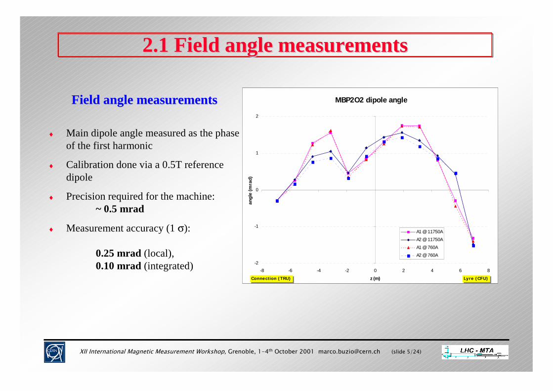
Field angle measurementsField angle measurements
♦ Main dipole angle measured as the phase of the first harmonic
♦ Calibration done via a 0.5T reference dipole
♦ Precision required for the machine: ~ 0.5 mrad
♦ Measurement accuracy (1 σ):
0.25 mrad (local), 0.10 mrad (integrated)
MBP2O2 dipole angle
-2
-1
0
1
2
-8 -6 -4 -2 0 2 4 6 8z (m)
angl
e (m
rad)
A1 @ 11750AA2 @ 11750AA1 @ 760AA2 @ 760A
Connection (TRU) Lyre (CFU)
XII International Magnetic Measurement Workshop, Grenoble, 1-4th October 2001 [email protected] (slide 6/24)
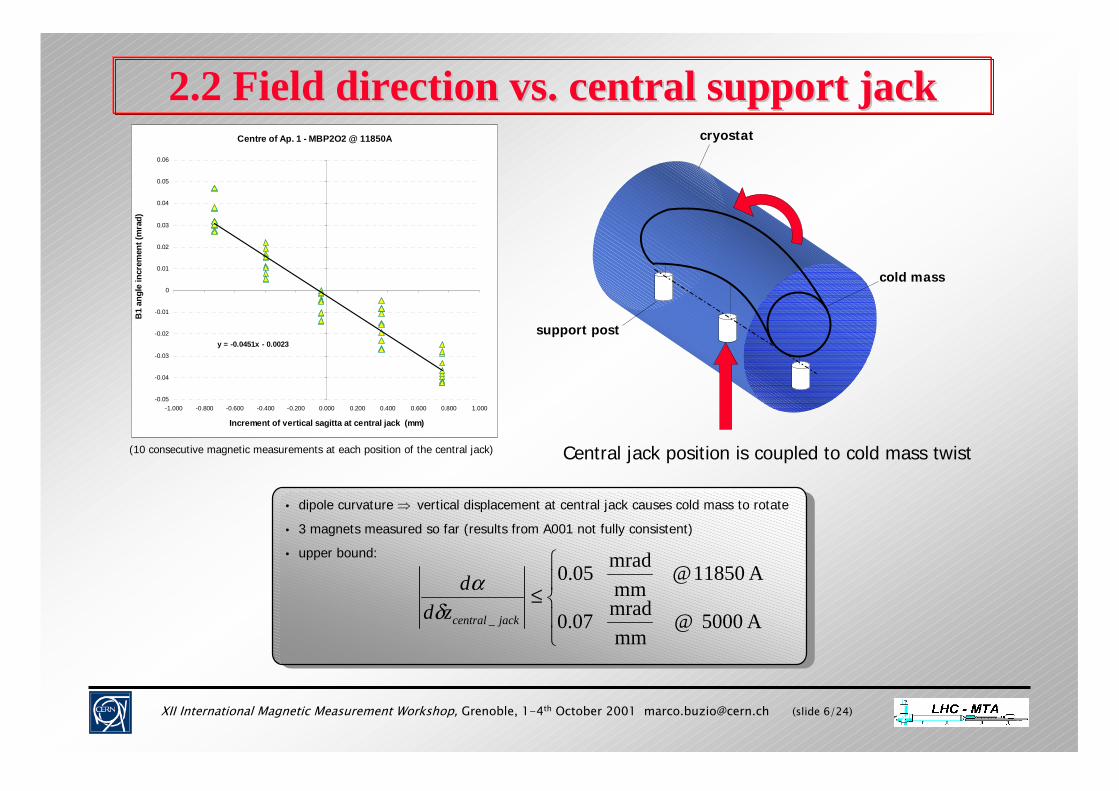
2.2 Field direction vs. central support jack 2.2 Field direction vs. central support jack Centre of Ap. 1 - MBP2O2 @ 11850A
y = -0.0451x - 0.0023
-0.05
-0.04
-0.03
-0.02
-0.01
0
0.01
0.02
0.03
0.04
0.05
0.06
-1.000 -0.800 -0.600 -0.400 -0.200 0.000 0.200 0.400 0.600 0.800 1.000
Increment of vertical sagitta at central jack (mm)
B1
angl
e in
crem
ent (
mra
d)
• dipole curvature ⇒ vertical displacement at central jack causes cold mass to rotate
• 3 magnets measured so far (results from A001 not fully consistent)
• upper bound:
• dipole curvature ⇒ vertical displacement at central jack causes cold mass to rotate
• 3 magnets measured so far (results from A001 not fully consistent)
• upper bound:
≤A 5000 @
mmmrad 07.0
A 11850 @mmmrad 05.0
_ jackcentralzdd
δα
(10 consecutive magnetic measurements at each position of the central jack)
cryostat
cold mass
support post
Central jack position is coupled to cold mass twist

XII International Magnetic Measurement Workshop, Grenoble, 1-4th October 2001 [email protected] (slide 7/24)
3.1 Magnetic alignment tests3.1 Magnetic alignment tests
I. Magnetic axes are needed in nominal working conditions
II. Mechanical and magnetic axes seem to coincide within 0.1~0.2 mm1, but mechanical axes are measured are not accessible at 1.9K ⇒ unproved extrapolation from room to cryogenic conditions is necessary
III. Corrector leads accessible only after cold tests
IV. Cross-check with measurements1 in industry for absolute accuracy and effects due to transportation
1 see Juan’s talk
Motivations for alignment tests at CERN

XII International Magnetic Measurement Workshop, Grenoble, 1-4th October 2001 [email protected] (slide 8/24)
3.2 Overall alignment test strategy3.2 Overall alignment test strategy
Cryogenic magnetic measurements with 15m shaft
The twin 15m coil shaft system measures dipole axis and field errors (multipoles) vs. excitation and powering history on the cryogenic test bench. The absolute position of the coil rotation axis is not known with precision.
twin 15m ceramic dipole coil shafts
xfield multipoles
magnetic axis(obtained by harmonic feed-down)
field reference system(centred on coil rotation axis)
B3
y // g
B2
B1

XII International Magnetic Measurement Workshop, Grenoble, 1-4th October 2001 [email protected] (slide 9/24)
3.3 Overall alignment test strategy3.3 Overall alignment test strategy
Cryogenic “cold mole” tests
The dipole is measured a second time with a traveling probe (“cold mole”), which detects the position of the magnetic axis of both dipole and correctors w.r.t. the standard {R,S,T} MAD dipole reference system (based on the reference beam orbit).
R
T-g
αααα
reference beam orbit
magnetic axis
cold mole
harmonic coil
mole parking + reference bench

XII International Magnetic Measurement Workshop, Grenoble, 1-4th October 2001 [email protected] (slide 10/24)
3.4 Overall alignment test strategy3.4 Overall alignment test strategy
Room-temperature “warm mole" tests
For most dipoles there will be no time to carry out mole measurements on the cryogenic test bench. Instead, the magnetic axis will be measured with a simpler room-temperature probe and extrapolated via a suitable warm/cold correlation.
R
T-g
αααα
XII International Magnetic Measurement Workshop, Grenoble, 1-4th October 2001 [email protected] (slide 11/24)
3.5 Overall alignment test strategy3.5 Overall alignment test strategy
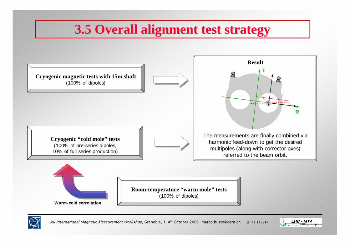
Result
The measurements are finally combined via harmonic feed-down to get the desired multipoles (along with corrector axes)
referred to the beam orbit.
R
TCryogenic magnetic tests with 15m shaft
(100% of dipoles)
Cryogenic “cold mole” tests(100% of pre-series dipoles,10% of full series production)
Room-temperature “warm mole” tests(100% of dipoles)
Warm-cold correlation

XII International Magnetic Measurement Workshop, Grenoble, 1-4th October 2001 [email protected] (slide 12/24)
4.1 Definition of dipole axis4.1 Definition of dipole axis
How to define a dipole axis ?How to define a dipole axis ?
♦ A perfect dipole has no axis, but a conventional one can be defined based on field errors.
♦ Axes based on high-order harmonics (defined by zeroing e.g. C10 C12 C14, which can be assumed to be generated by feed-down from strong C11, C13 and C15) lie close to the mechanical axis but correlate poorly in different magnets.
♦ Note that the axes of the harmonics needing corrections (C3, C4, C5) are ill-defined (they move with dynamic effects)

XII International Magnetic Measurement Workshop, Grenoble, 1-4th October 2001 [email protected] (slide 13/24)
4.2 Definition of dipole axis4.2 Definition of dipole axis
QCD dipole axis QCD dipole axis
The Quadrupole-Configured Dipole (QCD) is obtained by feeding opposite current in each half-coil through the voltage taps.
QCD axis has been chosen as the most convenient reference because of the following advantages:
♦Depends on the global coil shape (represents the geometry of the cold mass ⇒ long term stability)
♦Close (<200 µm) to cold bore geometrical axis (to be confirmed on a statistical basis)
♦Easy to measure with precision from feed-down even at extremely low current (<10 µm @ ±0.5A)

XII International Magnetic Measurement Workshop, Grenoble, 1-4th October 2001 [email protected] (slide 14/24)
5.1 Cold mole: test bench5.1 Cold mole: test bench• fully automatic motorized travelling probe
• 750 mm × ∅ 20 mm coil for QCD and harmonic measurements
• telescope+CCD camera transversal coil position sensor (same as for warm mole)
• operating in a vacuum for high optical accuracy despite large thermal gradients
• absolute coil position is recovered at external reference quadrupoles via laser tracker survey
• not optimised for mechanical axis measurement
• no on-board tilt sensor ⇒ cannot be used to measure field direction
• 1 unit only in production at Fraunhofer IPT, expected Q4 2001
• fully automatic motorized travelling probe
• 750 mm × ∅ 20 mm coil for QCD and harmonic measurements
• telescope+CCD camera transversal coil position sensor (same as for warm mole)
• operating in a vacuum for high optical accuracy despite large thermal gradients
• absolute coil position is recovered at external reference quadrupoles via laser tracker survey
• not optimised for mechanical axis measurement
• no on-board tilt sensor ⇒ cannot be used to measure field direction
• 1 unit only in production at Fraunhofer IPT, expected Q4 2001
mole
longitudinal transportation
sliding support to access both magnet apertures
cable receptacle
harmonic coil(dipole, quadrupole or higher-orders)

XII International Magnetic Measurement Workshop, Grenoble, 1-4th October 2001 [email protected] (slide 15/24)
5.2 Optical position sensor5.2 Optical position sensor
Note: the same system is used for warm/cold dipole moles & quadrupole scanning machine
• telescope+CCD camera transversal coil optical position sensor
• common to warm and cold MB moles + SSS scanning system
• LED light-spot generated in the front of the probe optically projected into coil centre (follows probe pitch and yaw)
• Range: XY up to ±7 mm @ 3 m distance – distance<20 m
• absolute accuracy:
20 µm @ 3 m distance (air)60 µm @ 20 m distance (air)30 µm @ 20 m distance (vacuum)
(in the transversal plane)
XY
travelling probe (mole)
LED light spot(optically projected in the centre of the coil)
telescope CCD camera + DSP XY measurement
XII International Magnetic Measurement Workshop, Grenoble, 1-4th October 2001 [email protected] (slide 16/24)
5.3 cold mole: axis transfer overview5.3 cold mole: axis transfer overview
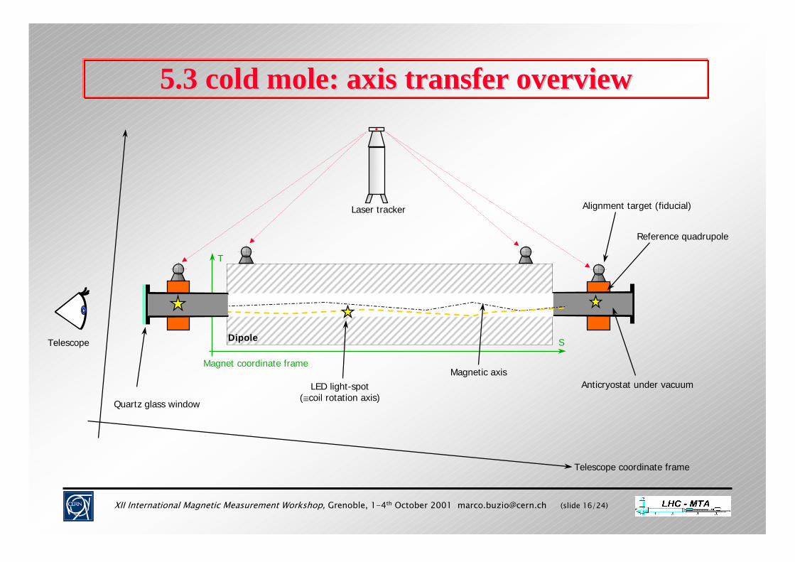
Telescope coordinate frame
Magnet coordinate frame
Dipole
Reference quadrupole
Telescope
Alignment target (fiducial)
Magnetic axisLED light-spot
(≅coil rotation axis)
Laser tracker
S
T
Anticryostat under vacuum
Quartz glass window

XII International Magnetic Measurement Workshop, Grenoble, 1-4th October 2001 [email protected] (slide 17/24)
5.4 cold mole: axis transfer detail5.4 cold mole: axis transfer detail
Telescope reference framex
y Magnet coordinate frame
Laser Tracker
Reference quadrupole (see G. Deferne’s talk)
QCD magnetic axis
LED light-spot(≡ search coil rotation axis)
Optical alignment targets (fiducials)
QCD Axis w.r.t. magnet frame →→→→ XY telescope measurement→→→→ harmonic measurement→ laser tracker →→→→ fiducialisation (EST/SU)→→→→ magnetic calibration
end result
→→→→ XY telescope measurement→→→→ harmonic measurement→ laser tracker →→→→ fiducialisation (EST/SU)→→→→ magnetic calibration
end result
R
T

XII International Magnetic Measurement Workshop, Grenoble, 1-4th October 2001 [email protected] (slide 18/24)
5.5 Cold mole: summary5.5 Cold mole: summary
Main benefits of cold mole measurementsMain benefits of cold mole measurements
1) Indispensable tool to transport axes and multipoles to the reference orbit frame.
2) Cold magnetic axes (of both dipole and correctors) can be given directly w.r.t. magnet fiducials, bypassing mechanical extrapolations used to define the cold reference orbit
3) Relative alignment between dipole and correctors can be verified directly with one instrument (bypassing the transformations to the fiducial and to the reference orbit frames)

XII International Magnetic Measurement Workshop, Grenoble, 1-4th October 2001 [email protected] (slide 19/24)
5.6 warm mole5.6 warm mole
warm mole
• fully automatic motorized travelling probe
• 750 mm × 400 turns dipole-compensated harmonic coil
• telescope+CCD camera transversal coil position sensor
• absolute coil position recovered at external reference marbles via laser tracker survey
• not optimised for mechanical axis measurement
• 1 unit operational + 1 expected Q1 2002
Front reference marble (transportation)
Back reference marble (optical system)

XII International Magnetic Measurement Workshop, Grenoble, 1-4th October 2001 [email protected] (slide 20/24)
5.7 warm mole: axis transfer overview5.7 warm mole: axis transfer overview
Telescope coordinate frame
Magnet coordinate frame
Dipole
Reference support
Telescope
Alignment target (fiducial)
Magnetic axisLED light-spot
(≅coil rotation axis)
Laser tracker
T
S

XII International Magnetic Measurement Workshop, Grenoble, 1-4th October 2001 [email protected] (slide 21/24)
5.8 warm mole: axis transfer detail5.8 warm mole: axis transfer detail
Telescope reference framex
y Magnet coordinate frame
Laser Tracker
Mole sitting on rest positionon reference marble
QCD magnetic axis
LED light-spot(≡ search coil rotation axis)
Optical alignment targets (fiducials)
QCD Axis w.r.t. magnet frame→→→→ XY telescope measurement→→→→ harmonic measurement→ laser tracker →→→→ fiducialisation (EST/SU)→→→→ mechanical calibration
end result
→→→→ XY telescope measurement→→→→ harmonic measurement→ laser tracker →→→→ fiducialisation (EST/SU)→→→→ mechanical calibration
end result
R
T

XII International Magnetic Measurement Workshop, Grenoble, 1-4th October 2001 [email protected] (slide 22/24)
5.9 warm mole: results5.9 warm mole: resultsPre-series Noell 1 dipole magnetic axis (QCD)
wrt harmonic coil rotation axis
-1.400
-1.200
-1.000
-0.800
-0.600
-0.400
-0.200
0.000
0.200
0.400
0.600
0.800
0 2000 4000 6000 8000 10000 12000 14000 16000 18000
longitudinal position (mm)
axis
offs
et (m
m)
External aperture (radial)
Internal aperture (radial)
External aperture (vertical)
Internal aperture (vertical)
XII International Magnetic Measurement Workshop, Grenoble, 1-4th October 2001 [email protected] (slide 23/24)
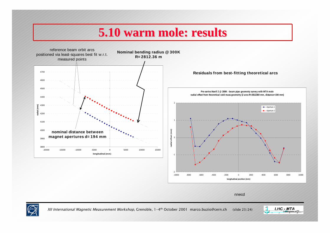
3800
3900
4000
4100
4200
4300
4400
4500
4600
4700
-20000 -15000 -10000 -5000 0 5000 10000 15000
longitudinal (mm)
radi
al (m
m)
5.10 warm mole: results5.10 warm mole: results
Pre-series Noell 2 @ 300K - beam pipe geometry survey with MTA mole radial offset from theoretical cold mass geometry (2 arcs R=2812360 mm, distance=194 mm)
-2
-1
0
1
2
-10000 -8000 -6000 -4000 -2000 0 2000 4000 6000 8000 10000
longitudinal position (mm)
rad
ial o
ffse
t (m
m)
Aperture 1
Aperture 2
Nominal bending radius @ 300K R=2812.36 m
nominal distance between magnet apertures d=194 mm
reference beam orbit arcs positioned via least-squares best fit w.r.t.
measured points
nnecd
Residuals from best-fitting theoretical arcs
XII International Magnetic Measurement Workshop, Grenoble, 1-4th October 2001 [email protected] (slide 24/24)
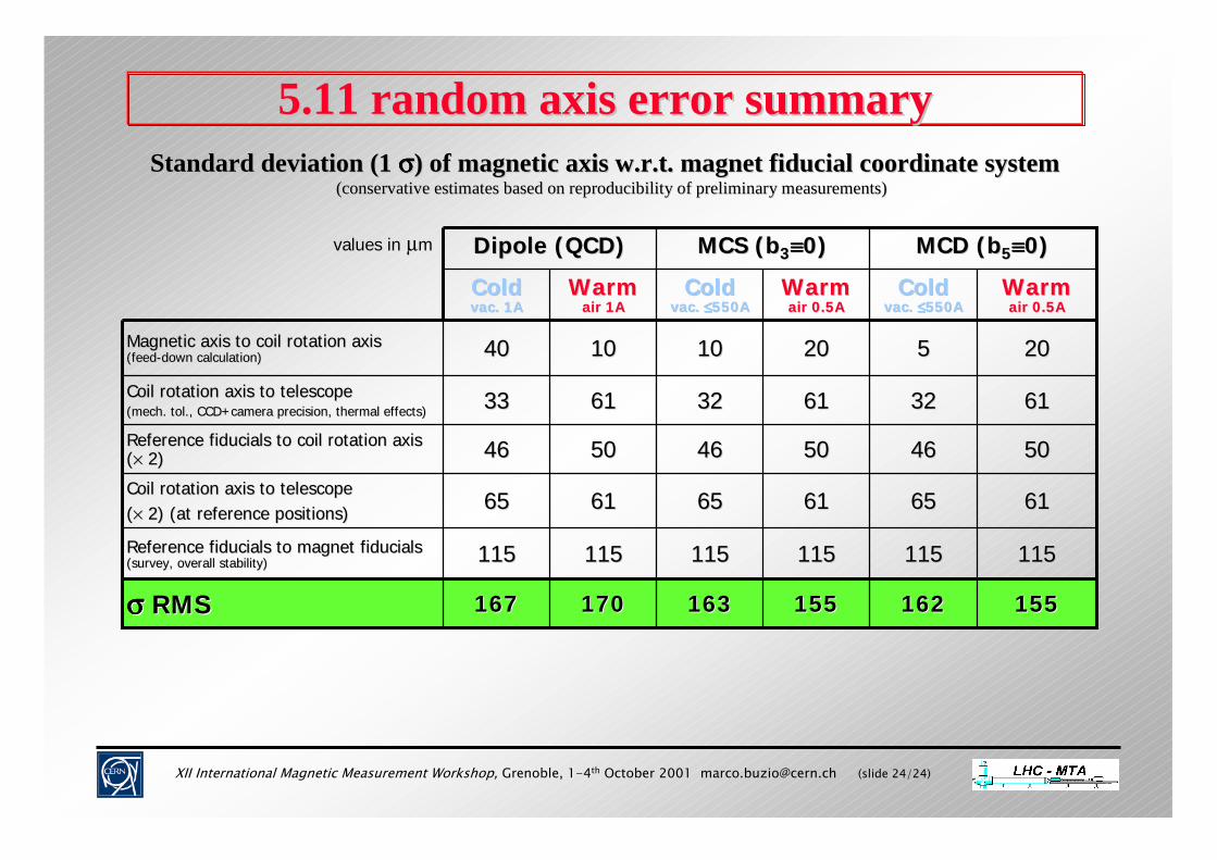
5.11 random axis error summary5.11 random axis error summary
155155162162155155163163170170167167σσσσσσσσ RMSRMS
115115
6565
4646
3333
4040
ColdColdvac. 1Avac. 1A
Dipole (QCD)Dipole (QCD)
115115
6161
5050
6161
1010
WarmWarmair 1Aair 1A
115115
6565
4646
3232
55
ColdColdvac. vac. ≤≤≤≤≤≤≤≤550A550A
MCD (bMCD (b55≡≡≡≡≡≡≡≡00))
115115
6161
5050
6161
2020
WarmWarmair 0.5Aair 0.5A
MCS (bMCS (b33≡≡≡≡≡≡≡≡00))values in µm
61616565Coil rotation axis to telescopeCoil rotation axis to telescope((×× 2) (2) (at reference positions)at reference positions)
61613232Coil rotation axis to telescopeCoil rotation axis to telescope(mech. (mech. toltol., CCD+camera precision, thermal effects)., CCD+camera precision, thermal effects)
50504646Reference Reference fiducialsfiducials to coil rotation axis to coil rotation axis ((×× 2)2)
115115115115Reference Reference fiducialsfiducials to magnet to magnet fiducialsfiducials(survey, overall stability)(survey, overall stability)
20201010Magnetic axis to coil rotation axisMagnetic axis to coil rotation axis(feed(feed--down calculation)down calculation)
WarmWarmair 0.5Aair 0.5A
ColdColdvac. vac. ≤≤≤≤≤≤≤≤550A550A
Standard deviation (1 Standard deviation (1 σσσσσσσσ) of magnetic axis w.r.t. magnet ) of magnetic axis w.r.t. magnet fiducialfiducial coordinate system coordinate system (conservative estimates based on (conservative estimates based on reproducibility of reproducibility of preliminary measurements)preliminary measurements)
XII International Magnetic Measurement Workshop, Grenoble, 1-4th October 2001 [email protected] (slide 25/24)
6.1 conclusions6.1 conclusions♦♦ Outlook Outlook
alignment test equipment needed for detailed study of pre-series dipole fully available as of end 2001
critical measurements will be cross-calibrated with multiple systems and cross-checked with results from other groups (LHC/MMS, EST/SU)
estimated accuracy in line with requirements and with comparable results in other superconducting accelerators
♦♦ Issues still to be assessed Issues still to be assessed
reproducibility of warm-cold QCD correlation dependence of axis deformation and field rotation upon thermal cycling, central jack position,
magnet current etc.. cross-talk between apertures in QCD mode ⇒ radial shift of QCD axis
XII International Magnetic Measurement Workshop, Grenoble, 1-4th October 2001 [email protected] (slide 26/24)
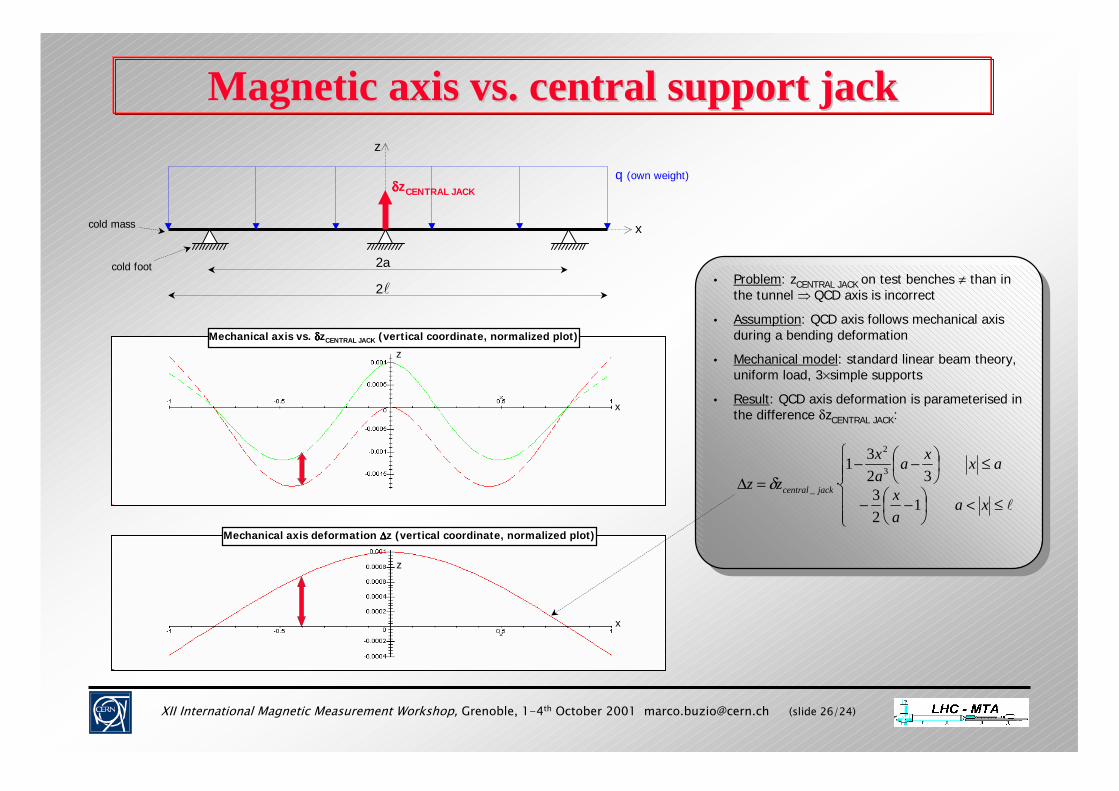
Magnetic axis vs. central support jackMagnetic axis vs. central support jack
• Problem: zCENTRAL JACK on test benches ≠ than in the tunnel ⇒ QCD axis is incorrect
• Assumption: QCD axis follows mechanical axis during a bending deformation
• Mechanical model: standard linear beam theory, uniform load, 3×simple supports
• Result: QCD axis deformation is parameterised in the difference δzCENTRAL JACK:
≤<
−−
≤
−−=∆
�xaax
axxaax
zz jackcentral
123
3231
·3
2
_δ
Mechanical axis vs. δδδδzCENTRAL JACK (vertical coordinate, normalized plot)
z
x
Mechanical axis deformation ∆∆∆∆z (vertical coordinate, normalized plot)
z
x
z
2�
2a
q (own weight)
x
cold foot
cold mass
δδδδzCENTRAL JACK