of access control systems - Honeywell Specifier Programme · An important part of an overall...
40
A specifier’s guide to the security classification of access control systems March 2011 For other information please contact: British Security Industry Association t: 0845 389 3889 f: 0845 389 0761 e: [email protected] www.bsia.co.uk © This document is the copyright of the BSIA and is not to be reproduced without the written consent of the copyright owner. Form No. 132. Issue 2
Transcript of of access control systems - Honeywell Specifier Programme · An important part of an overall...

A specifier’s guide to thesecurity classification
of access control systems
March 2011For other information please contact:
British Security Industry Associationt: 0845 389 3889
f: 0845 389 0761e: [email protected]
© This document is the copyright of the BSIA and is not to be reproduced without the written consent of the copyright owner.Form No. 132. Issue 2

Page 2
Contents
1. Foreword 52. Introduction 63. Scope 64. Definitions and Abbreviations 75. Referenced Documents 116. System Components 12 6.1 Access control system components and their operation 12 6.2 Credentials 12 6.3 Readers 12 6.3.1 Standalone readers and keypads 12 6.3.2 System readers 12 6.3.3 Combined Reader / Controller 12 6.3.4 Offline Readers 13 6.4 Controllers 13 6.5 Power Supply Units (PSUs) 13 6.6 PC & Software 13 6.7 Programmers 14 6.8 Door Contact 14 6.9 Egress devices 14 6.9.1 Normal Egress 15 6.9.2 Emergency Egress 15 6.10 Operation 157. Security Levels 15 7.1 Security Grading 15 7.1.1 Access Point Grading 16 7.1.2 Other components 16 7.2 Cross reference to existing standards 168. Door Types 189. Lock Types 19 9.1 Maglocks 19 9.2 Shearmags 20 9.3 Electric strikes 20 9.4 Solenoid Latch 21 9.5 Solenoid handle locks 22 9.6 Motor locks 22 10. Entrance Control 23 10.1 Door Type v Grading 23 10.2 Turnstiles 24 10.2.1 Types of Turnstile 25 10.2.2 Types of Speedgate 2511. Reader/Token Technology 28 11.1 Passive / Active 28

Page 3
12. Special Features 28 12.1 Security related 28 12.1.1 Anti-passback 28 12.1.2 Anti-tailgate 29 12.1.3 Multi card usage 29 12.1.4 Human verification 29 12.1.5 Lift Control 29 12.1.6 Automatic Number Plate Recognition (ANPR) 30 12.1.7 Long Range readers for vehicle identification 30 12.1.8 N Factor Authentication 30 12.1.9 Logical Access Control 31 12.1.10 Visitor Management 31 12.2 Non Security 31 12.2.1 Time and Attendance (T&A) 3113. Interconnection Communication Requirements 32 13.1 WIRED Interconnections 32 13.2 WIRELESS Interconnections 33 13.3 Interconnection Security 3314. Building Access 33 14.1 Access equipment locations 33 14.2 Escape routes 33 14.2.1 Panic escape 34 14.2.2 Emergency escape 3415. Installation Requirements 3416. Configuration 3417. System Management 34 17.1 Backups 34 17.2 Resilience 35 17.3 Token Management 35 17.4 Reporting 35 17.5 Data Protection 35 17.6 Information Security 3518. Service and Maintenance 3519. Interoperability 3620. Example Applications 37 20.1 Grade 1 37 20.2 Grade 2 37 20.3 Grade 3 38 20.4 Grade 4 3821. Appendices 39 21.1 Appendix A – Interconnection bus system definitions 3922. Further Reading 3923. Acknowledgments 40

Page 4
BACnet® is a registered trademark of American Society of Heating, Refrigerating andAir-Conditioning Engineers (ASHRAE).
Bluetooth® is a registered trademark of Bluetooth SIG
Fieldbus® is a registered trademark of Fieldbus Foundation
LonWorks® is a registered trademark of the Echelon Corporation
Mifare® is a registered trademark of NXP Semiconductors
Modbus® is a registered trademark of Schneider Automation, Inc.
Profibus® is a registered trademark of Profibus Nutzerorganisation e.V.
Wi-Fi® is a trademark of the Wi-Fi Alliance
© BSIA 2011The material in this guide is for general information purposes only and does not and is not intended to constitute professional advice. No liability is accepted for reliance upon this guide.

Page 5
1. Foreword
An integrated and structured security risk management plan is essential for all buildings, both business related
and residential, where there are multiple uses or occupancy. An effective and professionally installed access
control system must form part of such a management plan.
Modern technology has allowed designers and manufacturers of access control systems to constantly push the
boundaries and produce products with an ever increasing number of technical and innovative features. Whilst
such technology should be embraced, care must be taken to ensure that these new technologies and applica-
tions are suitable for the intended use, compatible with existing technologies, practical, effective and, where
required, aesthetically in tune with the building.
Standards and Codes play an ever important role in ensuring that products installed meet the exact requirements
and operational needs of each individual application. They also offer some reassurance that emerging technolo-
gies are assessed and where necessary tested and certificated before being installed in buildings, thereby
offering specifiers, tenants and owners of large multiuse/multi occupancy buildings some degree of protection
and peace of mind.
ACPO Secured by Design therefore welcomes this latest update to the BSIA Specifiers Guide for Access Control
Systems. The technical content, advice and guidance contained within this document will inform and assist
those involved in the specification and installation of access control systems. It will also be a valuable source of
information to those that may be asked to assess the suitability of access control systems, such as the insur-
ance industry, building facilities management and the police service.
Jon ColeNational Operations Manager
Association of Chief Police Officers
Secured by Design
Page 6
2. Introduction
An access control system is an effective form of security and its benefits include:
1. An important part of an overall electronic security system
2. Enhanced security of employees, buildings and assets
3. Ability to work with other in-house security measures
4. Reduction in the overall cost of managing security
Specifiers need to be aware of the potential contribution of access control systems when surveying premises, and should understand how and when to specify them to effectively control or restrict access. There is a suite of European standards which have been adopted as British standards and which adequately cover the system de-sign, installation and equipment requirements of access control systems. However, they do not provide guidance on the grading of systems - that is the purpose of this document.
This document has been produced as a guide to assist specifiers in grading access control systems in line with other security applications. It lists the various depths of security that may be required, and identifies what the specifier should take into account when specifying access control systems.
The main determinant of the security level required will be the outcome of the risk assessment of the premises, and this in turn will influence the choice and design of access control system to be used.
Design of the access control system should take account of the Equality Act and Disability Discrimination Act so that physical aspects permit goods and services to be accessible to disabled people.
Where this guide is used in conjunction with a recommendation to comply with Secured by Design requirements then specifiers should consult with Police Crime Prevention Design Advisors (CPDA).
For further information about Secured by Design refer to www.securedbydesign.com
3. Scope
This guide provides details of security grading for access control systems. It covers system components includ-ing tokens, barriers, doors and interconnection methods. The document provides security levels for:
• Reader / Token Technology
• Physical security classification of doors
• Electromechanical locks

Page 7
4. Definitions and Abbreviations
4.1 Definitions
Access Action of entry or exit from a security controlled area.
Access control installation The hardware part of the access control system
Access control system An electronic system restricting access (i.e. entry into and/or exit from a security controlled area).
Access group A number of users sharing the same access level
Access Level User authority based on a set of rules used to determine where and when a credential has authorized access. This may include special conditions such as specific allowed times.
Access point The location at which access can be controlled by a door, turn-stile or other secure barrier
“Airlock” Although commonly called an “airlock” this is technically incorrect. Preferred terms are: Interlocking doors / Man trap / Person Trap / Personal transfer units / Security Booth / Security Vestibule / Commodity transfer units
A combination of two or more doors, turnstiles, barriers, etc required to be used in sequence in order to gain access to a controlled area. The release of a subsequent door is conditional upon the closure of the previous door used. This design is effec-tive against piggybacking and tailgating can also be applied to vehicles. Some arrangements of interlocking doors are intended for transfer of goods such as money or commodities.
Alarm / Alert An indication to prompt human intervention.
Anti-passback A feature that traces individual credential access requests to a given area. It checks for granting of access not preceded by granting of exit (or vice versa) to check that the credential has not been “passed back” to another user. Also refer to hard anti-passback, soft anti-passback, logical anti-passback and timed anti-passback.
Anti-tailgate / Anti-piggybacking A system function that relocks the entry door or turnstile immediately upon closing and as quickly as possible after the authorised user has passed. This is to prevent an unauthorised person rushing through behind the user.
Area controlled anti-passback Operating mode which requires the user to be present in a designated security controlled area in order to be able to enter another security controlled area

Page 8
Authentication The system recognition process comparing a user’s credential with recorded credentials.
Badge A type of Token
Biometric Any measurable, unique physiological characteristic or personal trait used as a credential. (e.g. fingerprint, hand or face geom-etry, retinal/eye, face, voice, signature or keyboarding dynam-ics).
Card A type of Token
Chip Serial Number (CSN) A number stored on an RFID device
Code Usually a 4 or 5 digit code which a user has to remember; termed a PIN (Personal Identification Number).
Commodity Transfer Unit See “Airlock”
Common code A PIN used by all users of a single access control system.
Common token A token unique to a particular access control system, or reader, with all user tokens identical.
Configuration The process or the result of enabling/disabling systems func-tions and/or changing values as allowed by pre-set rules.
Controlled area / Protected area / The area accessed by the presentation of valid recognition data.Security controlled area
Credential Any token/memorized information/biometric image used to identify an individual to an access control system in order to verify user access rights.
See also badge, token, biometric, PIN.
Door forced Unauthorised opening of an access point
Door Held Alarm Detection that a door has not closed within a defined time after access has been granted.
Dual Access / Dual Badging A function granting access only after two sequential authorised access requests are made within a programmable limited time period.
Dual Occupancy A function, which counts the number of users entering and leaving the area and grants egress only if at least two author-ised users remain in the area at all times.
Duress alarm / alert An alarm/alert generated by a user being coerced into providing access. The alarm is hidden at the access point and typically generated by use of an alternative PIN that also grants access.

Page 9
Egress The action of leaving the security controlled area.
Elevator Control See Lift Control
Fail locked / Fail secure The securing of a locking mechanism in the event of an access control system failure (usually power failure).
Fail open / fail safe / fail unlocked The release of a locking mechanism in the event of an access control system failure (usually power failure).
Fail Maintained Locking device to which the removal of power does not change the locked or unlocked mode.
False acceptance The granting of access to an unauthorised user
False Acceptance Rate A percentage of erroneous recognition of users granting access.
False rejection The denial of access to an authorised user
False Rejection Rate A percentage of erroneous recognition of users denying access.
Hard anti-passback A feature, which generates an alert and denies further access following violation of anti-passback rules.
Interlocking doors See “Airlock”
Keypad A data entry point for the input of a numeric or alphanumeric code (PIN) into an access control system.
Lift Control A functionality restricting the use of a lift (elevator) car.
Logical anti-passback Operating mode which requires user validation when leaving a security controlled area in order to be able re-enter and vice versa
Man trap / Person trap See “Airlock”
Personal Identification Number (PIN) A sequence of characters allocated to an individual user of an access control system keypad.
Personal (or Personnel) transfer unit See “Airlock”
Power supply That part of an access control system which provides power for the operation of the system or any part of thereof
Reader An input device, which “reads” a credential consisting of spe-cific identifying characteristics.
Request-to-Exit (REX) A device used to initiate free egress.

Page 10
Security Booth / Security Vestibule See “Airlock”
Soft Anti-passback A system feature, which grants access but generates an alert following violation of anti-passback rules.
Standby In relation to power supply, refers to the operation of the system (perhaps with reduced functionality) when the mains supply is unavailable. Usually this is achieved with a battery backup.
Tailgating / Piggybacking When a person, without using a credential, passes through a portal with a person for whom access has been granted.
Tamper detection A means for the detecting unauthorised interference with a component of an access control system.
Tamper protection Methods used to protect an access control system or part thereof against deliberate interference.
Time Scheduled Free Access A period of time according to pre-set rules for which the sys-tem does not control access.
Timed Anti-passback A system feature, which denies access to a given area to a cre-dential following violation of anti-passback rules until a defined period of time has elapsed.
Token A credential containing a readable unique identifier. e.g, cards, keys, tags, etc. Tokens can be read from a distance (non-con-tact or proximity tokens) or by contact (where the token must physically touch a reader).
Transaction An event corresponding to the release of a door following an access granted by the system.
Uninterruptible power supply (UPS) A device that maintains power to equipment (typically a com-puter) for a short period after mains failure. Its use is intended to prevent loss or corruption of data.

Page 11
4.2 Abbreviations
ANPR Automatic Number Plate RecognitionBS British Standard (from BSI British Standards Institute - www.bsigroup.com) CSN Chip Serial NumberDDA Disability Discrimination ActEN European Norm (standard, see BS)FAR False Acceptance RateFRR False Rejection RateID IdentificationLAN Local Area NetworkLPCB Loss Prevention Certification Board (www.redbooklive.com)LPS Loss Prevention Standard (from LPCB)NSI National Security Inspectorate (www.nsi.org.uk)PAS Publicly Available Specification (see, BS)PC Personal ComputerPIN Personal Identification NumberPSU Power Supply UnitREX Request-to-ExitRFID Radio Frequency IdentificationSLA Service Level AgreementSSAIB Security Systems and Alarms Inspection Board (www.ssaib.org)STS Security Technical Schedule (from Warrington Certification – www.warringtonfire.net) T&A Time and AttendanceUPS Uninterruptible power supplyWAN Wide Area NetworkWCL Warrington Certification Limited
5. Referenced Documents
BS EN 50133-1:1997 System requirements for access control systems, British Standards
BS EN 50133-2:2000 Component requirements for access control systems, British Standards
BS EN 50133-7:1999 Application guidelines for access control systems, British Standards
EU Working Time Directive (officially: Directive 2003/88/EC of the European Parliament and of the Council of 4 November 2003 concerning certain aspects of the organisation of working time)
IEE Wiring Regulations (latest edition)
LPS 1175 Requirements and testing procedures for the LPCB approval and listing of intruder resistant building components, strongpoints, security enclosures and free standing barriers, LPCB
NSI Code of Practice for Planning, Installation and Maintenance of Access Control Systems, NSI
PAS 24: 2007+A1: 2009 Enhanced security performance requirements for door assemblies, British Standards
PAS 68: 2010 Impact test specifications for vehicle security barriers, British Standards

Page 12
SSAIB Code of Practice for Access Control Systems, SSAIB
STS201: Enhanced security requirements for doorsets and door assemblies for dwellings to satisfy the requirements of PAS23 and PAS24, Warrington Certification
STS202: Requirements for burglary resistance of construction products including hinged, pivoted, folding or sliding doorsets, windows, curtain walling, security grilles, garage doors and shutters, Warrington Certification
BSIA Guide to Integrated Security Management Systems (Form 203), BSIA
Disability Discrimination Act 1995 & Disability Discrimination Act 2005 as amended
Equality Act 2010
6. System Components
6.1 Access control system components and their operationAn access Control System typically consists of a number of components from those that identify a person to those that authorise access. This section defines the main components in the system.
6.2 CredentialsA credential is a physical or tangible object, a piece of knowledge or a facet of a person’s physical being that enables an individual to gain access to a controlled area. Typically, credentials can be something you know (such as number or PIN), something you have (such as an access token), something you are (such as a biometric feature) or any combination of these. The typical credential is an access card, key fob, or other token.
6.3 ReadersAccess control readers may be classified by functions they are able to perform:
6.3.1 Standalone readers and keypadsThese have all the necessary inputs and outputs to control door hardware, as well as the memory and processing power to make access decisions independently. A standalone reader usually has one credential (e.g. PIN) and anyone knowing that PIN is allowed access through the door. The access decision logic can be made on the unsecure side of the access point.
6.3.2 System readers These devices read the credential from a card, or a PIN from a keypad and forwards the data to a controller. Most also provide an audio and visual method of feedback to indicate to the user whether access has been granted or denied.
6.3.3 Combined Reader / ControllerAs the name suggests, some system readers combine the functions of the reader and the controller in a single device. They hold a copy of the user database allowing them to make the decision to grant or deny access even if the controller cannot access the network. The access decision logic can be made on the unsecure side of the access point.

Page 13
6.3.4 Offline ReadersAn Offline reader differs from a combined reader / controller in that it does not maintain a database. With offline readers, the card itself holds the information that defines which doors are valid, and the times that access is allowed. The offline reader analyses this information and grants or denies access as appropriate.
6.4 ControllersIn most networked systems, one or more readers and the relevant door hardware is connected to a controller. These intelligent devices hold information in a local database required to decide whether a user is allowed through a door at a given date and time. The controller should also be capable of working off-line should the network communications fail for any reason.
Controllers can be connected to a PC through a variety of interconnection methods. Subject to how the controllers communicate, alarm events and card transactions may be passed to other controllers. This communication can be used for event driven actions, such as activating a sounder in a different area, or for access control features such as anti-passback. This communication is often dependent upon the PC or master controller being operational and full communications being on-line.
In addition to storing credentials, access groups and time zones, controllers will also store transactions should the system go off-line. Then, once the communication path with the system PC or master controller is re-established, the audit trail of access and alarm events will be uploaded with date & time stamp.
Operation of the system is highly dependent on the controller, so consideration should be given to the number of readers connected to any one device. Failure of one controller could affect a large number of controlled points depending on the system design.
6.5 Power Supply Units (PSUs)The power supply requirements should be carefully checked to ensure that all necessary door hardware, including the chosen locks, can be supported simultaneously. It may be necessary to utilise a separate power supply for controlling the lock hardware.
If a controller does not contain its own power supply then a suitable PSU should be provided in accordance with the manufacturers recommendations.
It is recommended that systems be provided with battery back-up in the event of mains failure. The duration of standby should be agreed with the end user. It is recommended that the power supply standby batteries are monitored.
6.6 PC & SoftwareThe system software may range from a simple standalone solution installed on a PC in an insecure area to a secure solution installed on a server in a controlled area. Web based systems are also available which allow an authorised person to gain access from any PC. Careful consideration should be given to the level of access available, and the location of the software or any terminals.
It is important to ensure that the PC provided for the system meets the minimum specification recommended by the manufacturer.
In place of a standard PC or server, some systems now provide a controller with an industrial grade PC pre-loaded with the system software. This will be battery backed overcoming issues caused by mains failure. These devices are connected directly to either a dedicated or existing LAN/WAN or can be used in more traditional wiring configurations.

Page 14
For more information about IP Based Networks refer to the BSIA Guides listed in the Bibliography.
In addition to access control features, the software may offer ID badging, integration with Intruder or Video Surveillance Systems, lift control etc. There are a wide variety of options available providing a better return on investment and a system that is easier to use and manage.
Some access control systems are now ‘hosted’, with the software located offsite. Administration of the system can be handled by the end user via a web browser, or it may be fully managed by a third party on behalf of the end user, reducing the need for on-site user training, PC hardware and ID badge production equipment.
6.7 ProgrammersIf a system is not PC based, then a means of programming the system must be supplied, with a minimum requirement of adding and deleting cards. This could be via a hand held device, or keypad and display forming part of the master controller.
These devices should be password controlled and are often very simple to operate by means of Yes/No questions, allowing basic access to be granted which can also include day/time schedules on larger systems. For many entry level applications this solution is adequate for the level of security required BUT manual records of card holder details must be kept so that lost/stolen cards can be deleted as it is unlikely the user record will be ‘named’. The system may also lose the facility to provide historical reports of who went where and when.
6.8 Door ContactA door contact is used for sensing opening and closing of a controlled door. Typical door contacts are made up of two component parts: the contact switch that is installed on the door frame; and a magnet that is mounted on the door.
Door contacts are used to monitor events such as:
• Door forced alarm – a door being opened without the use of the reader or normal egress device• Door held alarm – someone holding the door for another party or blocking the door for delivery or to return
later if they have no card.
Door contacts are recommended for higher grades of security (see Section 7.1)
Grade 1 Grade 2 Grade 3 Grade 4
Optional Y Y
Recommended Y Y
Table 1 – Use of Door contacts
6.9 Egress devicesHaving replaced (or disabled) standard lock sets in most access control installations, a means of providing controlled and authorised egress may be required so that any door monitoring contact is isolated for the approved period of the door release. This is commonly achieved with a simple Request-to-Exit switch, a movement sensor or a reader.

Page 15
6.9.1 Normal EgressEgress buttons are the most common form of device used. These can be simple light duty rocker switches, heavy duty buttons or a touch sensitive switch – all of which send a signal to the controller to release the door lock.
If a movement sensor is used this should be designed for the purpose. The detection pattern must be fully adjustable to ensure that the door release is only signalled by a person wishing to leave and not simply walking past the door or standing in the general vicinity.
In addition to normal egress, a means of override will be required from the secure area and possibly from outside of the controlled area.
For fail safe locking, such as a maglock or shear lock, where no key override is supplied, then a means of removing the power from the lock from the unsecure side may be required if this is the only entrance into the secure area – or if all doors are controlled (see 6.9.2).
6.9.2 Emergency EgressTo comply with local authority and Building regulations and to meet local Fire officer requirements, emergency egress must not depend on the operation of the access control systems controller, software etc. In the case of Fail Safe locks this is normally supplied by a green breakglass device. Operation of this device will remove power from the lock and the door is no longer secure. This device should be monitored to show its operation. Opening an access control monitored door in this way would generate an alarm event (Door Forced).
It is considered best practice to use a double or even triple pole breakglass units to ensure both positive and negative connections are released and reporting of breakglass activation in the case of the triple pole unit.
6.10 OperationWhen a credential is presented to a reader, the information is sent to a door controller. The controller compares the credential to a list of authorised users in the database. If there is a match (taking account the day/time of the request if applicable), the controller will send a signal to release the door lock, gate, barrier or turnstile. The controller will then ignore a door open signal generated by a monitor contact to prevent an alarm. A signal is sent to the reader to provide audio/visual feedback to the user to show that access is granted.
Generally entry is controlled and exit is uncontrolled. If exit is to be controlled, a second reader is used on the opposite side of the door, otherwise, a Request-to-Exit is used.
An important safety feature to consider is the ability to exit a door if the access control system is unavailable – this is called mechanical free egress. This is usually achieved with a green breakglass device which removes power from the lock. This must always conform to local authority Building regulations and Fire Officer requirements.
7. Security Levels
7.1 Security GradingAccess control points are graded according to the type of business and risk associated with the premises being secured. The grade applies to the protected area and not the overall system, therefore mixed grades may be utilised within any premises.

Page 16
7.1.1 Access Point GradingThere are four grades:
Grade 1 (Low Risk)A standalone lock (PIN or token) controlled in a public area for low risk situations.
Grade 2 (Low to medium risk)An on-line system utilising token’s or PIN’s to prevent access to the premises. Events are received in real-time on the monitoring software.
Grade 3 (Medium to high risk)An on-line system using two factor authentication to prevent access to the premises. Events are received in real-time on the monitoring software.
Grade 4 (High risk)An on-line system using single factor biometric or above to prevent access to the premises. Events are received in real-time on the monitoring software. When using biometrics careful selection of the quality to reduce FAR shall be made.
The grade applied to each point may increase with time according the requirements, for example card only during office hours and card+PIN outside hours.
7.1.2 Other componentsWithin any system the main components that control and monitor the system, for example the pc and software must meet the highest grade installed. The following should also be considered for all systems:
• PC / Software access, auto lock when operator away from PC• UPS on PC• Battery backup of controllers• Logical access• Encryption• Physical location of PC 7.2 Cross reference of grading to other schemesTable 2 shows the approximate relationship between the recommendations for grading in this guide, the security classification used in the European Standard EN 50133-1 and the classification used by NSI in their Code of Practice for Planning, Installation and Maintenance of Access Control Systems 2011 version.
Note: The NSI document (being a replacement to NACP 30 published in 1990) was in the process of completion at the time of writing of this guide and therefore the grade may not correspond exactly.

Page 17
Access Security Grade
EN50133 Classification
NSI Level Access Grade
4 3B 3 factor
4 3B L4 2 factor including biometric
4 2B L4 1 factor biometric
3 3B L3 2 factor (non-biometric)
2 2B L2 Token
2 1B L2 PIN
1 2A L1 Standalone lock with token
1 1A, 1B L1 Standalone lock with PIN
Table 2 - Security Grading Cross Reference

Page 18
8. Door Types
There is an obvious association between the security provided by a door and its frame and the associated access control system. It can however be recognised that the access control system may be supplemented outside normal opening hours by extra security provision. The following table gives an indication of the relationship between the holding force applied by the access control locking system and the materials of a door together with any testing and certification of the door.
Holding Force
Hollow Core Softwood / uPVC
Hardwood Steel
3kN Internal door – not security, privacy only
Internal door – not security, privacy only
5kN Internal door – not security, privacy only
PAS 24, STS201Internal door – low risk only
7kN Internal door – not security, privacy only
PAS 24, STS201LPS 1175 SR 1, STS 202 BR 1Low risk external doors (use with separate night locking)
Medium risk internal doors
PAS 24,LPS 1175 SR 2, STS 202 BR 2
Medium risk external doors (use with separate night locking)
Medium risk internal doors
10kN PAS 24,LPS 1175 SR 2, STS 202 BR 2 (depending on door)
Medium risk external and internal
PAS 24,LPS 1175 SR 2, STS 202 BR 2
Medium risk external and internal
12kN PAS 24,LPS 1175 SR 2, STS 202 BR 2 (depending on door)
Medium risk external and internal
LPS 1175 SR 3, STS 202 BR 3
Medium / high risk external
Key:LPS 1175: Certified by LPCB to LPS 1175 with Security Rating (SR) as indicated. (SR can be from 1 to 8)
PAS 24: tested to meet PAS 24 (published by British Standards)
STS201: Certified by Warrington Certification to PAS 23/24 (formerly WCL1)
STS202: Certified by Warrington Certification to STS 202 (formerly WCL2) with Burglary Rating (BR) as indi-cated. (BR can be from 1 to 6)
For details of Warrington Certification and LPCB see 5. Referenced Documents
Table 3 - Door types and holding force

Page 19
kN Pounds (lbs) kg
0.45 100 45.4
1.0 225 102
1.5 337 153
3.0 674 306
5.0 1125 509
7.0 1570 713
10.0 2250 1020
12.0 2700 1220
15.0 3370 1530
Note: Conversions are approximate
Table 4 - Comparison of forces in lbs, kg and kN
9. Lock Types
9.1 Maglocks
Magnets
DescriptionAn electric magnet is perhaps the simplest means of remotely locking and unlocking doors. These again can vary tremendously in cost and performance ranging from 1kN to 14kN holding forces. The principle is very simply an electro-magnet and a ferrous plate that are in contact when the door is closed. The magnetic field is only on when an electric current (12v dc) is passed through the electromagnet. Because of this they are only available as fail unsecure (unlocked) and this reason alone they are generally seen as low security solutions.
SecuritySecurity is generally low as power failure to the magnet will release the door. Often only one magnet is used at the head of the door (top). The door can become vulnerable if attacked at the base through either the door failing or sufficient leverage being gained to break the holding force on the magnet.

Page 20
InstallationInstallation of the electromagnet is generally very easy and straight forward with power only being required to the frame. It is important for the alignment between the electro magnet and the ferrous plate to be correct to achieve the specified holding force. If the electromagnet is mounted on the top of the doorframe it is important that it does not restrict the height through the door sufficiently for it to become a health and safety issue. There have been a number of indicents where people have injured themselves on overhead electromagnets mounted on the doorframe.
ApplicationsThe electromagnet is generally used on low security doors with medium to heavy traffic. It is suitable on internal doors or external doors if there is a further mechanical lock for use at night or outside normal business hours. 9.2 ShearmagsA shearmag is similar to a maglock in that it relies on the attraction between an electromagnet and a plate on the edge of the door to lock. However in this case, the plate has a number of protruding metal pins on the surface, with matching recesses on the face of the magnet. When the door is locked, the electromagnet pulls the plate onto the face of the magnet. In this position the holding strength is then provided by the metal pins which are held within the recesses of the magnet. This provides much greater holding force than a conventional maglock, typically in the order of 7kN and upwards depending on size and type. Shearmags are always fail unlocked in operation and often require larger amounts of power to operate.
9.3 Electric strikes
DescriptionAn electric strike, or as it is sometimes described an electric release, is perhaps one of the most popular methods of unlocking a door electrically. It works on the principle of a solenoid which, when powered, moves a small pin that in turn engages or disengages a blocking mechanism which then allows a moving plate (usually referred to as the staple) to be released. This allows the release of a lock’s latch from the keep in the frame.
SecurityThe electric release is not always seen as the most secure means of electrically locking a door. They do however vary tremendously in their holding power from 1.5kN of side force up to 14kN or more on some of the higher security versions. Some versions are available with a monitoring switch that can detect whether the latch is engaged. This can save the need for a door monitor. The fact that the release is fitted to the doorframe also means that the doorframe material and size affect the security. Most strikes can be specified fail secure (locked) or fail insecure (unlocked), this being the status of the lock when power is withdrawn.

Page 21
InstallationGenerally easy to install as the strike is mounted in the door frame in the place of a conventional lock strike, so it is relatively easy to get electrical power (usually 12V dc ) to the unit. It is important that the latch on the lock is of the correct dimensions to work with the strike and the fitting needs to be precise to ensure the two units engage and work correctly without binding.
ApplicationsThe electric strike is generally used on low to medium security doors with medium to heavy traffic. It is suitable on internal doors or external doors if there is a further mechanical lock for use at night or outside normal business hours.
9.4 Solenoid Latch
Solenoid Locks
DescriptionA solenoid lock works in a similar way to an electric strike but the mechanism is contained within the lock case. The solenoid moves a pin, which engages or disengages the handle movement to the latch. In the locked position the handle will move as normal but will not connect to the latch, so the handle moves freely but has no effect. In the unlocked position the lock will respond like a conventional lock with movement on the handle pulling the latch in.
SecurityThis type of lock can achieve quite high levels of security as the lock will behave much like a traditional lock under attack. Most of these locks operate with a deadlocking latch lock, which in most instances will not give quite the high level of engagement as a standard deadlock. Like an electric release these can be specified as fail secure or fail insecure. These can be specified with different functions inside to outside. For example the inside lever handle can always be active (for emergency egress) but the external handle is only engaged when the solenoid is operated.
Installation Installation can be a bit more involved and specialist, the main challenge is to get cabling to the back of the lock mortise on the door where the lock is to be installed. This will involve a door loop to transfer the cable from the frame to the door leaf. On a timber door this may also involve drilling a 5mm hole across the width of the door leaf. One of the benefits of the solenoid lock is that it appears to be a conventional lock from outward appearances and will match closely other locks and door furniture on a site.

Page 22
ApplicationsThe Solenoid lock is generally used on medium security doors with medium to heavy traffic. It is suitable on internal doors or external doors up to a medium security application. Some solenoid locks have a built in mechanical deadbolt for dead locking for out of hours.
9.5 Solenoid handle locksThese operate like a conventional mechanical latch lock, but with the ability for either one or both handles to be electrically disabled. When an open signal is sent to the lock the controlled handle is then able to retract the bolts and the door can be opened. Models are available with either one or both handles controlled. The models where only the handle on the insecure side is disabled are suitable for escape routes and any area where there is free exit. Models where both internal and external handles are disabled are suitable for areas where access is restricted in both directions. Solenoid handle locks typically have a holding force in the range of 7-10kN and are available with either fail locked or fail unlocked operation.
9.6 Motor locks
Motor Locks
DescriptionIn outward appearance they appear very similar to a solenoid lock but rather than a solenoid have an electric motor that drives a dead bolt.
SecurityThis type of lock can achieve as high a security level as any mechanical single point lock generally and will behave much like a traditional lock under attack. Most of these locks operate with a deadbolt, which in the correct door and frame installation can achieve high levels of security. In the event of a power failure the lock will remain in the status it was in at the time of the power failure.
Installation Installation can be more involved and specialist, the main challenge is to get cabling to the back of the lock mortise on the door where the lock is to be installed. This will involve a door loop to transfer the cable from the frame to the door leaf. On a timber door this may also involve drilling a 5mm hole across the width of the door leaf. One of

Page 23
the benefits of the motor lock is that it appears to be a conventional lock from outward appearances and will match closely other locks and door furniture on a site. On many motor locks they require a small control box, which usually needs to be fitted in the vicinity of the door, often above a false ceiling on the secure side of the door.
ApplicationsThe motor lock is generally used on higher security doors with medium to low traffic. This is because the lock takes a few seconds to withdraw the deadbolt. For an office entrance at peak times it would not be the best choice. It is suitable on both high security internal and external doors.
Holiding force Grade
3kN 1
5kN 2
7kN 3
>=10kN 4
Table 5 - Holding Forces - recommendation by grade
10. Entrance Control
Entrance control includes pedestrian gates, barriers, turnstiles and doors. Entrance control solutions form a part of the overall access control security classification. Entrance Control products require an access control reader to be integrated with them so that users can present their credentials. The Entrance Control product increases the security level of the access control system by either providing a physical barrier to restrict unauthorised access or by providing a method of detecting unauthorised access and generating an alarm.
10.1 Door Type v GradingThe following table defines the type of allowable physical security based upon grade of access system.
Access Point Types (Entrances)
Grade 1 Grade 2 Grade 3 Grade 4
Hollow Core external door
Softwood external door
Single arm pedestrian barrier
Single arm vehicle barriers
UPVC, Full or part glazed external door
Hollow Core internal door
Softwood internal door
Low-level pedestrian entrances
Roller shutter doors with windows or access doors
Bottom skirted vehicle barriers
Solid hardwood door
Full height pedestrian entrances.
Roller shutter doors
Top and bottom skirted vehicle barriers meeting a full height perimeter wall / fence
Full height sliding vehicle gate
Surface or shallow Vehicle road blocker / Rising kerbs (see PAS 68:2006 and PAS 68:2006)
Steel doors
High security doors
Interlocking Doors e.g. Personal transfer units orCommodity transfer units
Deep Vehicle road blocker / Rising kerbs(see PAS 68:2006
Table 6- Entrance Selection

Page 24
10.2 TurnstilesThe major difference between turnstiles and doors is that they restrict passage, usually allowing only one person to pass at a time. They can also enforce a single direction of passage and can stop people that have not paid a fee or presented correct identification. There are numerous ways that they can be used and in addition to access control they can be used for Direction Control (e.g. Single direction exit from a property so that visitors must go to a controlled entrance) and Revenue Control (e.g. At a barrier requiring use of a ticket or coin).
Turnstiles are used in a variety of locations such as public-transport stations, office lobbies, toilets, visitor attractions, stadiums, etc.
As a security feature some turnstiles offer much greater security than others. For example a full height turnstile can hinder a person from gaining access at an unattended location whereas a half-height turnstile can be jumped over. The latter may be suitable in an office lobby environment where access to the building lobby will have required entrance through a lockable door and reception staff can monitor the turnstile use.
Turnstiles can be used as the main method of access control (e.g. in a lobby) or be used in combination with access control of other entrances and exits (e.g. to permit people to leave without use of the access control system but enter using only an access controlled entrance).
Many designs of turnstile are available. Some of these have advantages over other types and overcome problems in usage. For example the temporary need to open the turnstile entrance to allow free flow of people or goods may be impossible with certain designs.
General Features of Turnstile DesignPurchasers should consider many features of a turnstile before purchasing.
• How easy and obvious should it be to use?• How will the turnstile be supplied, delivered and erected• How easy is it to supply power to the turnstile?• Is appearance important?• How fast should it operate? The slower the throughput, the more lanes will be required.• How many lanes are required? Will they fit in the available space?• Will the restrictions of the turnstile need to be removed from time to time or are there alternative routes?• Would the turnstile prevent access or exit in the case of a fire?• How tall should it be (to prevent jumping or climbing)?• How strong should it be? How high a force should it resist?
It is particularly important to consider the requirements of the Disability Discrimination Act.

Page 25
10.2.1 Types of Turnstile
Tripod Barrier – A turnstile of traditional appearance where three arms on a base (like a three legged stool) rotate to allow passage.
Tripod barrier
Optical Turnstile – These do not have a traditional barrier and instead use a detection method (e.g. infrared beams) and sound an alarm if unauthorised access is attempted.
Optical turnstiles are the safest pedestrian solution as there are no moving barriers that will cause injury. This also makes them the ideal solution for wheelchairs. They could also be considered the most discreet and aesthetic solution. However, they are intended for use in well-managed reception areas where aesthetics is a priority.
Optical turnstile
Speedgates – These have a form of motor driven barrier that is Rising, Swinging or Sliding depending on its method of moving into or away from the passage lane. These combine optical detection technology with a physical barrier. They can be normally open, in which case they close in front of an unauthorised person, or normally closed, opening when a person is authorised.
10.2.2 Types of speedgate
Rising barrier Swinging barrier Sliding barrier

Page 26
Entrance gate – This is a motor driven gate that swings to allow passage. Frequently these are now madeof glass.
Some models may have detection beams but most do not. The lack of detection before or after the barrier means that these products are not ideal for high throughput areas; they are usually installed as additional devices for wheelchair users or occasional wide .
Entrance turnstile – This is constructed like three gates attached to a vertical pole (like a short revolving door).
Entrance gate Entrance turnstile
Full height turnstiles – These are usually rugged metal constructions tall enough to walk through and often associated with football stadiums.
Full height turnstile “Airlock” / security booth
“Airlock” / Security booths – These are constructions that work on a principle often described as an airlock. The person passes the first door which then closes before a second door opens. These can also be constructed using a rotating screen with an opening; the user steps through the opening into its centre and waits for the opening to rotate to the opposite side before leaving.
Revolving security door – Similar in appearance to a standard revolving door but incorporating access control and of higher strength.

Page 27
Turnstile type DDA compliant1
Physical security level2
Typical appearance
Speed3 Ease of use
Typical cost
Emergency egress4
Tripod barrier No Medium Prominent Slow15-25
Medium Low – medium
Hindered
Optical turnstile
Yes Low – medium
Low key Fast60
Easy Medium Unhindered
Rising barrier
Yes Medium
Medium Fast60
Medium
Medium – high
Unhindered
Sweeping barrier
Medium Fast60
Medium Unhindered
Sliding barrier Medium Fast60
Medium Medium
Entrance gate Yes Low – medium
Low key Slow15-25
Medium Low – medium
Medium
Entrance turnstile
No Medium Medium Slow15-25
Medium Medium Hindered
Full height turnstile
No High Highly prominent
Slow15-25
Awkward Medium Hindered
“Airlock” / Security Booth
No High Highly prominent
Slow6-10
Awkward High Hindered
Revolving security door
No Medium – high
Highly prominent
Slow10-15
Medium High Hindered
Key:1. Shows whether a product of this type is typically DDA Compliant. Products may vary and compliance can
be dependent on other circumstances.
2. Level of physical security compared to other turnstile types
3. Speed measured in persons per minute
4. Difficulty of gaining emergency access through the turnstile for a typical product of the type.
Table 7 - Comparison of Turnstile Types

Page 28
11. Reader / Token Technology
There are a number of different technologies that can be used as a token reader within an access control system. Each technology has a different level of security from the lowest (magnetic stripe) through to highest (biometric). Table 8 defines the suitability of the different reader technologies according to the grade of system being installed.
Grade 1 Grade 2 Grade 3 Grade 4
PIN Y Y Y1 Y3
Magnetic Y Y
Proximity Y Y Y1
RFID Y Y Y1 Y2
Biometric Y Y Y Y
Key:1. When used with another technology in 2 factor mode.2. When used with biometrics (use of CSN is not allowed).3. Only when used as third factor.
Consideration should also be made to the possibility of duplication of the card number used. The type of technology used will determine the probability of a duplicate number occurring and its potential to being used to gain access to the system.
Note: When using a biometric system the manufacturers FAR and FRR figures should be checked to ensure that they can meet the system requirements.
11.1 Passive / ActiveTokens can be obtained in either a passive form (no batteries) or an active form (with batteries). Active tokens typically provide a longer read range (> 10m), however they will require replacing over the lifetime of the system with the frequency dependent upon their usage.
12. Special Features
This section covers a number of security and non-security related features that may be utilised to enhance the security of the system. The choice of additional features should be discussed with the end user.• What is it• How it works• Advantages• Disadvantages
12.1 Security related
12.1.1 Anti-passbackAnti-passback is designed to detect whether a users credentials are used to enter an area when the system already believes the user to be in that area. This feature can be useful to stop a user who has entered an area from passing their token to another person outside the area. Two forms of anti-passback exist, namely hard anti-passback and soft anti-passback.

Page 29
• Hard anti-passback disallows a second access to an area if a valid exit has not previously been registered and generates an alarm.
• Soft anti-passback does allow a second access to an area if a valid exit has not previously been registered but generates an alarm.
Anti-passback rules are generally reset after a preset period after valid entry, at a fixed time each day, on exit from site or manually as an over-ride.
12.1.2 Anti-tailgateAnti-tailgate is a feature designed to prevent a situation where an unauthorised person attempts to enter or exit a security controlled area by passing through the access controlled point at the same time or immediately after a valid user. Two forms of anti-tailgate exist, namely hard anti-tailgate and soft anti-tailgate:
• Hard anti-tailgate employs physical means such as turnstiles to restrict movement
• Soft anti-tailgate does not prevent the unauthorised person but uses detection methods to generate an alarm.
12.1.3 Multi card usageThe system should be flexible enough to support different token technologies (e.g. Mifare®, Magstripe, 125Khz) to grant access on a single system. In this instance, each registered user should be capable of having multiple tokens assigned to them.
12.1.4 Human verificationTo increase the security of a system, a challenge or video verification mode is often available. When a token is presented at a reader, an operator at a PC is presented with the stored photograph of the user, together with a live image from a camera viewing the reader. Depending on whether the operator identifies the person in the live image against the displayed photograph, access can be manually granted or denied.
Specific personal data (name, details etc.) may also be displayed to the operator to aid identification.
Systems can provide human verification via audio rather than visual means, by integrating with multiple IP based intercoms for remote door control. Event audit trails can provide information on who either answered or initiated call, call time, date, relevant door, duration and action taken.
12.1.5 Lift ControlLift control is an extension to the concept of access control, using the user’s credentials to grant access to floors, rather than granting access through a door.
A token reader is fitted in each lift cab, using technologies compatible with the rest of the system. Depending on the user’s access rights, access to one or more floors may be granted. If the user does not have access to a given floor, the button for that floor is disabled. “Free access” is sometimes provided to allow anyone access to certain floor/s (e.g. ground floor).
For maximum flexibility, the lift control system should be capable of controlling multiple lift shafts simultaneously.

Page 30
12.1.6 Automatic Number Plate Recognition (ANPR)Access into and/or out of car parks can be automated by the use of ANPR. A camera is used to capture an image of the vehicle’s number plate, and this number is recognised and compared against a list of authorised vehicles stored in a database.
To improve the reliability of an ANPR system, the camera should be located where vehicles are lane controlled or constrained by a narrow width, where the vehicles are viewed head on and as close as possible.
Tailgating can be a problem, so measures are recommended to restrict this possibility (e.g. speed hump, barrier or electric gates).
12.1.7 Long Range readers for vehicle identificationSome readers are available which have an extended reading range, often over 10m (33ft). In addition, some readers can successfully read a passing tag at speeds up to 200km/hr (125mph).
When using such readers, it is important to consider their position and use, to avoid a single token being detected by multiple readers, as this may activate multiple barriers.
12.1.8 N Factor AuthenticationUser authentication in an access control system requires recognising certain data related to the user. Typically, credentials can be something you know (such as number or PIN), something you have (such as an access token), something you are (such as a biometric feature) or any combination of these.
Depending on the required security of the system, one or more of these factors may be used in combination to provide single, dual or multi-factor authentication:
• Single Factor authentication is where the user is identified against one element, e.g. something you are, such as a biometric.
• 2 factor authentication is where the user’s credentials are checked between two of the elements, e.g. something the user is and something the user knows such as biometric + PIN.
• 3 factor authentication is where the user’s credentials are checked between all three elements, e.g. something the user is, has and knows such as biometric + card + PIN.

Page 31
12.1.9 Logical Access ControlLogical access control enhances the security of a computer network by restricting a user from logging onto a computer system unless the access control system has previously granted that user access into the relevant area.
This requires a close integration between the access control system and the computer login system to ensure that the credentials for each can be cross referenced.
Logical access can also be useful to detect “hackers” by identifying attempts by a user to remotely access a computer system, when the user is physically on the premises.
12.1.10 Visitor ManagementVisitor Management allows visitors to a site temporary access to some or all areas within that site. It is important that visitor details can be quickly entered onto the system, often by pre-registration. Information to be considered for pre-registration includes the person being visited, visitor arrival and departure times, access rights to be given to the visitor and possibly even the visitor’s photo-ID image. A visitor badge is then printed on a card or label printer when the visitor arrives.
Visitor details can be made valid for a single visit, or for a predetermined period (e.g. contractors).
If visitor data is not pre-registered, the relevant information must be entered when the visitor arrives. Groups of visitors are often selectable as a group, and their status processed as a single action.
Some systems typically assign dual access for the visitor token such that the visitor and host must present their tokens to gain access to an area. This prevents the visitor from freely accessing areas without the host being present whilst providing an audit trail of the visitors whereabouts.
12.2 Non Security
12.2.1 Time and Attendance (T&A)A time and attendance system logs and monitors the arrival and departure times of staff and calculates number of hours worked and numbers of outstanding hours to be worked that day / week / month. Reports can then be issued by user, department etc.
When required, the system should meet standards set by the EU Working Time Directive.
Such systems can be a standalone dedicated T&A solutions or use information taken from integration with a suitable access control system. In either case, they should be capable of making flexible calculations on hours worked to suit bespoke site requirements. These include basic/overtime hours worked, flexi time calculations, complex and varied shift patterns and administer planning for labour and forecasting. Holiday and absence pre scheduling and booking are often possible.
A facility to export T&A data to a company payroll system improves the overall usability of the system.
Page 32
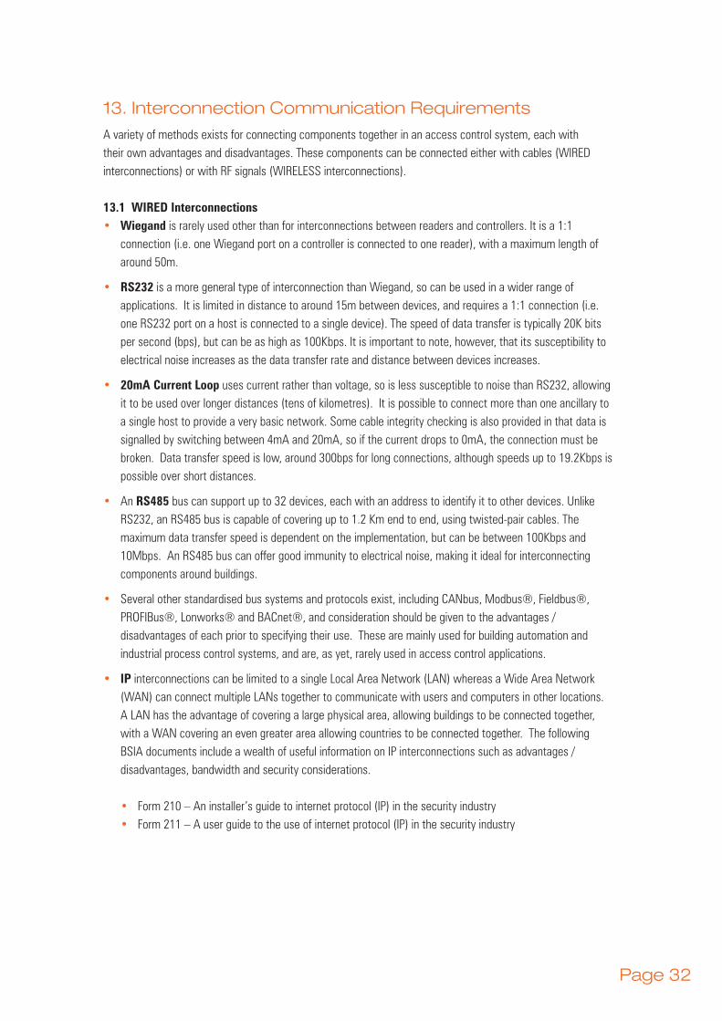
13. Interconnection Communication Requirements
A variety of methods exists for connecting components together in an access control system, each with their own advantages and disadvantages. These components can be connected either with cables (WIRED interconnections) or with RF signals (WIRELESS interconnections).
13.1 WIRED Interconnections• Wiegand is rarely used other than for interconnections between readers and controllers. It is a 1:1
connection (i.e. one Wiegand port on a controller is connected to one reader), with a maximum length of around 50m.
• RS232 is a more general type of interconnection than Wiegand, so can be used in a wider range of applications. It is limited in distance to around 15m between devices, and requires a 1:1 connection (i.e. one RS232 port on a host is connected to a single device). The speed of data transfer is typically 20K bits per second (bps), but can be as high as 100Kbps. It is important to note, however, that its susceptibility to electrical noise increases as the data transfer rate and distance between devices increases.
• 20mA Current Loop uses current rather than voltage, so is less susceptible to noise than RS232, allowing it to be used over longer distances (tens of kilometres). It is possible to connect more than one ancillary to a single host to provide a very basic network. Some cable integrity checking is also provided in that data is signalled by switching between 4mA and 20mA, so if the current drops to 0mA, the connection must be broken. Data transfer speed is low, around 300bps for long connections, although speeds up to 19.2Kbps is possible over short distances.
• An RS485 bus can support up to 32 devices, each with an address to identify it to other devices. Unlike RS232, an RS485 bus is capable of covering up to 1.2 Km end to end, using twisted-pair cables. The maximum data transfer speed is dependent on the implementation, but can be between 100Kbps and 10Mbps. An RS485 bus can offer good immunity to electrical noise, making it ideal for interconnecting components around buildings.
• Several other standardised bus systems and protocols exist, including CANbus, Modbus®, Fieldbus®, PROFIBus®, Lonworks® and BACnet®, and consideration should be given to the advantages / disadvantages of each prior to specifying their use. These are mainly used for building automation and industrial process control systems, and are, as yet, rarely used in access control applications.
• IP interconnections can be limited to a single Local Area Network (LAN) whereas a Wide Area Network (WAN) can connect multiple LANs together to communicate with users and computers in other locations. A LAN has the advantage of covering a large physical area, allowing buildings to be connected together, with a WAN covering an even greater area allowing countries to be connected together. The following BSIA documents include a wealth of useful information on IP interconnections such as advantages / disadvantages, bandwidth and security considerations.
• Form 210 – An installer’s guide to internet protocol (IP) in the security industry• Form 211 – A user guide to the use of internet protocol (IP) in the security industry
Page 33
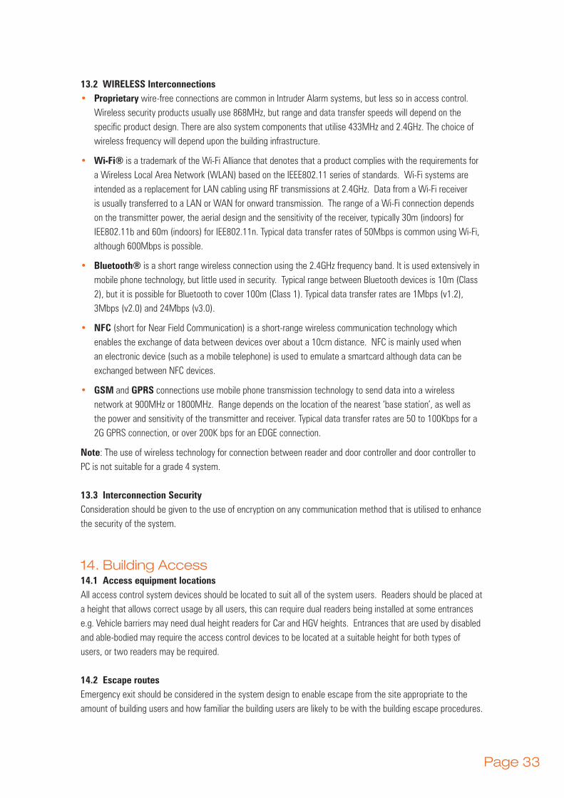
13.2 WIRELESS Interconnections• Proprietary wire-free connections are common in Intruder Alarm systems, but less so in access control.
Wireless security products usually use 868MHz, but range and data transfer speeds will depend on the specific product design. There are also system components that utilise 433MHz and 2.4GHz. The choice of wireless frequency will depend upon the building infrastructure.
• Wi-Fi® is a trademark of the Wi-Fi Alliance that denotes that a product complies with the requirements for a Wireless Local Area Network (WLAN) based on the IEEE802.11 series of standards. Wi-Fi systems are intended as a replacement for LAN cabling using RF transmissions at 2.4GHz. Data from a Wi-Fi receiver is usually transferred to a LAN or WAN for onward transmission. The range of a Wi-Fi connection depends on the transmitter power, the aerial design and the sensitivity of the receiver, typically 30m (indoors) for IEE802.11b and 60m (indoors) for IEE802.11n. Typical data transfer rates of 50Mbps is common using Wi-Fi, although 600Mbps is possible.
• Bluetooth® is a short range wireless connection using the 2.4GHz frequency band. It is used extensively in mobile phone technology, but little used in security. Typical range between Bluetooth devices is 10m (Class 2), but it is possible for Bluetooth to cover 100m (Class 1). Typical data transfer rates are 1Mbps (v1.2), 3Mbps (v2.0) and 24Mbps (v3.0).
• NFC (short for Near Field Communication) is a short-range wireless communication technology which enables the exchange of data between devices over about a 10cm distance. NFC is mainly used when an electronic device (such as a mobile telephone) is used to emulate a smartcard although data can be exchanged between NFC devices.
• GSM and GPRS connections use mobile phone transmission technology to send data into a wireless network at 900MHz or 1800MHz. Range depends on the location of the nearest ‘base station’, as well as the power and sensitivity of the transmitter and receiver. Typical data transfer rates are 50 to 100Kbps for a 2G GPRS connection, or over 200K bps for an EDGE connection.
Note: The use of wireless technology for connection between reader and door controller and door controller to PC is not suitable for a grade 4 system.
13.3 Interconnection SecurityConsideration should be given to the use of encryption on any communication method that is utilised to enhance the security of the system.
14. Building Access14.1 Access equipment locationsAll access control system devices should be located to suit all of the system users. Readers should be placed at a height that allows correct usage by all users, this can require dual readers being installed at some entrances e.g. Vehicle barriers may need dual height readers for Car and HGV heights. Entrances that are used by disabled and able-bodied may require the access control devices to be located at a suitable height for both types of users, or two readers may be required.
14.2 Escape routesEmergency exit should be considered in the system design to enable escape from the site appropriate to the amount of building users and how familiar the building users are likely to be with the building escape procedures.

Page 34
There are two emergency escape scenarios that should be considered in the access control system design: Panic escape and Emergency escape.
14.2.1 Panic escapeWhere members of the public use buildings or where there are high numbers of employees, there is a heightened risk of panic during an emergency evacuation. Users of the escape route may not be familiar with the operation of the escape hardware, they must be able to easily find and operate the hardware located on the exit door (see BS EN 1125).
14.2.2 Emergency escapeWhere the building users are all familiar with the site and the emergency exits, panic during an emergency evacuation is less likely. Operation of emergency exit devices and handles are acceptable as long as it is with one single operation to release the locking device (see BS EN 179).
15. Installation Requirements
Consideration should be given to industry codes of practice and any relevant standards as defined in section 5.
16. Configuration
The configuration of access control systems is carried out by the use of various system software tools. According to the authority of the system user, functions may be enabled and disabled, system values may be modified.
Typically, an access control system configuration may be seen as falling into two categories:
• System hardware configuration, i.e. readers, controllers and other control equipment – this step is carried out by the installer
• User database configuration, i.e. cardholder details, time schedules, access levels etc. – this step is usually carried out by the customer or end-user.
The system user database will contain information about personnel probably including a photographic image which may be printed onto a suitable credential. Additional information may be printed on the reverse of the access control credential, this may be site safety information e.g. fire emergency procedure instruction. There may also be information about what to do with the card if found.
Use of the system application software is restricted by passwords and/or PINs which may be simple, user generated, or may be time limited with complexity enforced or be linked to the user’s Operating System password rules.
17. System Management
As with any system, efficient management is key to ensuring the security and operability of the access control system is maintained. This section covers some of the main elements that shall be considered within any system.
17.1 BackupsThe access control system should have a suitable backup regime defined to ensure that in the event of any

Page 35
failure of the PC hardware, historic events can be recovered if required. This can take the form of a simple backup from the access control system through to a fully automated nightly backup of the server.
17.2 ResilienceAll door controllers should be battery backed to provide continuous operation in the event of a power failure. If the server is critical for operational use, for example fire alarm mustering, then this should also be provided with a suitable UPS. Controllers should retain any audit trail information in the event of a power failure.
17.3 Token ManagementThe management of tokens is critical to the secure operation of the system. The control and security of access to the system should be password protected to ensure that the registration of new users is controlled.
17.4 ReportingTo ensure that the system remains efficient regular reports should be run that check a range of events from the system, such as unauthorised access attempts, usage lists etc.
17.5 Data ProtectionAs the access control system will be storing personal data then it must be documented within the company’s data protection policy.
17.6 Information SecurityAccess to any terminals and servers that run the access control system must be secured from inadvertent access.
18. Service and Maintenance
To ensure the continued efficiency of any access control system throughout its lifespan, they should be regularly maintained.
A Service Level Agreement (SLA) should be agreed with a qualified maintenance provider (check the BSIA website for member companies). The SLA should include a preventative maintenance schedule (at least once per annum) detailing what is to be: tested, tightened, lubricated, replaced (etc) and the frequency. The SLA should also include a reactive maintenance agreement detailing what response times and repair times are expected.
The end user should ensure that the chosen maintainer is authorized by the manufacturer to service and maintain the system.
Due to the variety of components that are used in some access control systems, there is often a requirement for more than one maintenance contract to cover all of the system components. For example electronic access control and vehicle barriers could be from different maintenance providers. To ensure consistency with the maintenance service it maybe a consideration to have only one maintenance contract and allow that maintenance provider to contract out the other maintenance contracts that are required to fully maintain the access control system (back to back contracts).

Page 36
19. Interoperability
• Over the years, systems from different manufacturers have started to use common methods of interconnecting components, LAN technology being a common example. In addition, common communication protocols such as TCP/IP have also been developed. These developments have led to an increasing likelihood that systems from different disciplines can integrated to give a common benefit. This is called Interoperability.
• An integrated security solution can reduce cost and provide a return on investment by eliminating costly manual processes. However, the major benefit is the improved security that can be provided at a time when security is a great concern to all organisations whether they are in the public or private sector.
• Any system chosen must meet today’s requirements, but must also fit the customer’s needs into the future This is a difficult challenge, which requires predicting how the organisation may change and grow and ensure that the systems have the scope to expand to meet these needs.
• There are many advantages to integrating systems, the following list representing some of the major benefits:
• Different disciplines may be operable from a common user interface, where the operator can see access control events, intruder alarm activations and video activity on a single screen. This can make investigation much more straightforward and reduce the need to send security officers out to respond to security breaches.
• Access control and fire allows fire alarm mustering - know where your employees are at a given time. Furthermore, the access control system can monitor the fire alarm system to automatically release the appropriate electric locking mechanisms. The proposed link between the access control system and the fire system should be evaluated as part of the fire risk assessment.
• Access Control and other security detection systems can initiate pre and post-event video recording, linking the video clip with the event information. This can make searching for events more effective as it is much quicker to search for an event in the alarm log, rather than search through hours of video.
• Intruder & Hold up alarm system control functions can be managed by the access control system – allows the intruder alarm system to be unset on presentation of a card before entry is granted. If the user is not authorised to unset the system, access is denied.
• Initiate camera presets when specific pre-determined events occur, e.g. when entering a room in a bank, switch the camera to zoom onto the door to identify the individual.
• Use video with Time & Attendance system to detect / eradicate ‘buddy-clocking’, a practice where employees clock each other on and off work.
• Using an occupancy count from the access control system can reduce false alarms - the Intruder & Hold Up Alarm system can be notified not to set if the access control system is aware that not all users have exited the building.
• Building management systems are responsible for monitoring and controlling the environment of a building, for example lighting, heating and ventilation (HVAC). By integrating access control systems with BMS systems, the lighting can be switched on and the temperature can be increased to normal when a user enters an area.
• One of the fundamental objectives of a security system is to provide protection at the outermost

Page 37
perimeter of a property. A perimeter intruder detection system can be used, linked with video to provide early warnings and increased security through verification in the event of a breach. For example, external doors could be automatically locked if the perimeter system detects an abnormal event.
• By using smart card technology, cashless vending becomes a reality. The same card that gets you into the building can also hold money for the vending machines or canteen.
• Part of the definition of any system is the evaluation of risk within the business. Any system should evaluate and mitigate these risks by the careful selection of components and analysis of the requirements. The resulting system should aim to reduce any risks within the business that are associated with both people and property.
• When reviewing the opportunities for integration of different system components, consideration should always be given to the real advantages and benefits that integration brings to the customer in their specific situation in terms of increased security, increased efficiency, and reduced cost. If a clear business benefit cannot be identified then there is no requirement for integration.
• The definition and design of any integration requires careful consideration. Due care and attention should always be given when evaluating operational requirements to ensure that the system integrity is not compromised.
20. Example Applications
20.1 Grade 1
Application: Retail store, public area to private area
Number of doors: Low
Number of staff: Small
Risk level: Low
Customer requirement: Low cost solution, no audit trail
Lock type: Electric strike
Door type: Hollow core
System description: A standalone system utilising PIN or token access to secure the private areas from the general public.
20.2 Grade 2
Application: Hospital
Number of doors: Medium to high
Number of staff: Medium to high
Risk level: Medium
Customer requirement: Networked solution with audit trail and integration capability
Lock type: Maglock

Page 38
Door type: Solid wood
System description: A networked solution with tokens allowing full audit trail and definition of areas to allow varying access rights across the estate. The system allows for the remote control of the access point through the central software along with integration to other systems such as CCTV for remote monitoring of specific access conditions, such as door forced.
Specific areas may utilise higher security doors and locks depending upon the risk level and area to be protected.
20.3 Grade 3
Application: Data Centre
Number of doors: Low
Number of staff: Low
Risk level: Medium to high
Customer requirement: Networked solution with multi factor authentication to secure access to the data centre
Lock type: Shearlock or motorised
Door type: Solid hard wood
System description: A system providing two factor (i.e. card and PIN) or single factor biometric for increased security accessing the servers. This is coupled with a airlock to restrict access to one person at a time.
20.4 Grade 4
Application: Airport cargo screening (airside)
Number of doors: Small to Medium
Number of staff: Medium to high
Risk level: High
Customer requirement: Biometric solution with full audit trail and integrating CCTV
Lock type: Turnstile (full height)
Door type: Steel
System description: Turnstiles provide very secure access for one person at a time reducing the risk of tailgating. This coupled with biometrics ensures credentials cannot be duplicated or passed to other staff.

Page 39
21. Appendices
21.1 Appendix A – Interconnection bus system definitions
• Several other bus systems exist, but these are mainly used for industrial process control and are, as yet, rarely used in access control applications. These include:
• CANbus was originally designed for automotive applications, so works well in electrically noisy environments. The bus can support up to 64 devices, and its length varies depending on the data transmission speed, from 40m @ 1Mbps to 10Km @ 5Kbps.
• Modbus® is an open protocol for connecting industrial electronic devices, the main advantage being that it allows different types of devices to use a common serial bus. Unlike RS485 or RS232, Modbus defines the communications protocol, rather than the physical bus structure.
• Fieldbus® is a digital, serial communication system capable of supporting up to 16 devices per segment. Two implementations exist, H1 which has a data transfer speed of 31.25Kbps over a distance of 1.9Km, and HSE (High Speed Ethernet) with a data transfer speed of 100Mbps.
• PROFIBus® is a supplier-independent network standard, whose interface permits a vast application in processes, manufacture and building automation. PROFIBus is a communications protocol that can be used on physical buses such as Ethernet and RS485
• LonWorks® is a networking platform for connecting a large number of devices using standard bus structures such as RS232, RS485 or Ethernet, with data transfer rates in excess of 78Kbps (depending on the bus used).
• BACnet® (short for Building Automation and Control network) and allows communication over a variety of networks including Ethernet, ARCNET and RS-485. BACnet then simplifies the interoperability of devices on the different buses.
22. Further Reading
BSIA Guides – www.bsia.co.uk
BSIA Form 151 – User Guide to Access Control
BSIA Form 152 – An Installer Guide to Access Control
BSIA Form 173 – Guide to compliance with Disability Discrimination Act
BSIA Form 181 – Users practical guide to biometrics
BSIA Form 203 – Integrated Security Management Systems Guide
BSIA Form 210 – An installer’s guide to Internet Protocol (IP) in the security industry
BSIA Form 211 – A user guide to the use of Internet Protocol (IP) in the security industry
BSIA Form 242 – A Guide to Access Control for Manufacturing Sites
BSIA Form 246 – A Guide to Access Control for Offices
BSIA Form 261 – Installation of Access Control Systems Using IP Technology
BSIA Form 269 – A Guide to Access Control for the Education Sector

Page 40
BSIA Form 293 – A Guide to Access Control for the Healthcare Sector
Approvals and Certification Loss Prevention Certification Board (LPCB) – www.redbooklive.com
Secured by Design – www.securedbydesign.com
Warrington Certification – www.warringtonfire.net
23. Acknowledgments
The BSIA acknowledge the assistance given by the following member companies for the development of this guide.
ADT Fire and Security
Bradbury Security
Chubb Fire and Security
Gallagher Security Management Systems
G4S Technology
Integrated Design Limited (Fastlane Turnstiles)
Kaba
Romec Fire and Security
TDSi


![* * 0 Chapter 6 Java Methods. * * 0 Method Syntax [access specifier][qualifier] return type method name(argument list) Access specifier public – method.](https://static.fdocuments.in/doc/165x107/56649ebb5503460f94bc3caa/-0-chapter-6-java-methods-0-method-syntax-access-specifierqualifier.jpg)