OF :A PRESSURE TRANSDUCER - NASA · Forward V-I Characteristics of a Pressure Transducer (PT89)...
69
NASA CONTRACTOR REPORT !A "' FEASIBILITY STUDY OF :A MINIATURE SOLID-STATE PRESSURE TRANSDUCER by C. D. Pmker Prepared by RESEARCH TRIANGLE INSTITUTE Research Triangle Park, N. C. for Langley Research Center JATIONAL AERONAUTICS AND SPACE ADMINISTRATION WASHINGTON, D. C. JULY 1969 https://ntrs.nasa.gov/search.jsp?R=19690020346 2018-06-19T22:04:13+00:00Z
Transcript of OF :A PRESSURE TRANSDUCER - NASA · Forward V-I Characteristics of a Pressure Transducer (PT89)...
N A S A C O N T R A C T O R
R E P O R T
!A "' FEASIBILITY STUDY OF :A MINIATURE SOLID-STATE PRESSURE TRANSDUCER
by C. D. Pmker
Prepared by RESEARCH TRIANGLE INSTITUTE Research Triangle Park, N. C. for Langley Research Center
J A T I O N A L A E R O N A U T I C S A N D S P A C E A D M I N I S T R A T I O N W A S H I N G T O N , D. C. J U L Y 1 9 6 9
https://ntrs.nasa.gov/search.jsp?R=19690020346 2018-06-19T22:04:13+00:00Z
TECH LIBRARY KAFB, NM .. ~ ~
A FEASIBILITY STUDY OF A
MINIATURE SOLID-STATE PRESSURE TRANSDUCER
By C. D. Parker
Distribution of this report is provided in the interest of information exchange. Responsibility for the contents resides in the author or organization that prepared it.
Prepared under Contract No. NAS 1-7489 by RESEARCH TRIANGLE INSTITUTE
Research Triangle Park, N.C.
for Langley Research Center
NATIONAL AERONAUTICS AND SPACE ADMINISTRATION "
For sale by the Clearinghouse far Federal Scientif ic and Technical Information Springfield, Virginia 22151 - CFSTI pr ice $3.00
~-

FOREWORD
This report was prepared by the Research Triangle Institute, Research Triangle Park, North Carolina, on NASA Contract NAS1-7489, “A Feasibility Study of A Miniature Solid-state Pressure Transducer“. This work was administered under the direction of the Flight Instrument Division, Langley Research Center, by Mr. Charles A . Hardesty.
This investigation was performed by the Engineering and Environmental Sciences Division of the Research Triangle Institute under the general direction of Dr. R. M. Burger. Dr. J. J. Wortman was Laboratory Supervisor and C. D. Parker was the Project Leader. Other Institute staff members contributing to this effort include T. E. Pardue, F. T. Wooten, P. P. Rasberry, R. T. Pickett, and H. L. Honbarrier. Special thanks are also due to Mr. Hardesty of Langley Research Center for many valuable suggestions and assistance in testing the transducers.
iii
. .. .
ABSTRACT
The piezojunction effect, i.e., the sensitivity of the electrical characteristics of a p-n junction to mechanical strain, is summarized and its potential as a stress transducing mechanism discussed. Several configurations are described which provide for using the piezojunction effect as the sensory phenomenon in a pressure transducer, including a unique silicon needle sensor with a p-n junction in the needle apex. Needle sensors with excellent electrical characteristics were fabricated and demonstrated to be extremely sensitive to stress. These were fabri- cated into pressure transducers which detected pressure differentials of less than 100 VHg.
V

CONTENTS
Section
I INTRODUCTION
I1 THEORETICAL CONSIDERATIONS - A SUMMARY
Energy Band Considerations Deformation Potential Coefficients Calculated Values of y,(e)
Effect of Stress on p-n Junction Characteristics
I11 PRESSURE TRANSDUCER CONFIGURATION
The Silicon Needle Sensor Configuration The Simple Diaphragm The Indenter-Point Configuration Other Transducer Configurations Read-out Circuitry
IV CONCLUSIONS AND RECOMMENDATIONS
APPENDIX A THE RELATIONSHIP OF STRESS TO STRAIN
APPENDIX B NEEDLE FABRICATION PROCEDURE
APPENDIX C FUNDAMENTAL FREQUENCY OF A CIRCULAR DIAPHRAGM
Page
1
3
3 7 7
13
16
16 38 39 40 42
45
47
50
57
REFERENCES
vi i
58
LIST OF ILLUSTRATIONS
Figure
1. The Valence Bands of Silicon Near E = 0
Page
4
2. The Split Valence Bands of Silicon for a Compressional Stress 4
3. Ratio of Stressed to Unstressed Minority Carrier Density for a Hydrostatic, [loo], [Oll] and [lll] Uniaxial, Compressional Stress 8
4. Ratio of Stressed to Unstressed Minority Carrier Density for a [loo], [Oll] and [lll] Uniaxial, Tensional Stress 9
5. Ratio of Stressed to Unstressed Minority Carrier Density for a [lOO], [Oll] and [lll] Uniaxial, Compressional Stress 10
6. Ratio of Stressed to Unstressed Minority Carrier Density for a [loo], [Oll] and [lll] Uniaxial, Tensional Stress 11
7. Stressed and Unstressed V-I Characteristics of a p-n Junction (Silicon Needle Diode) 14
8. Schematic of a Silicon Needle Sensor 17
9. Photomicrograph of a Needle Sensor Prior to Metallization 17
10. An Illustration of the Needle Sensor Transducer Configuration 18
11. Oscillogram Illustrating the V-I-Stress Characteristics of a Needle Sensor (S#121) 19
12. A Shadow-profile of a Needle Sensor (S#l21) 20
13. V-I Stress Characteristics of a Needle Sensor with Leaky Reverse Characteristics 21
14. An Oscillogram of Frequently Observed Forward V-I Stress Characteris tics 23
15. A Shadow-profile Typical of the Sharpest Needle Sensors 23
16. A Basic Pressure Transducer with a Clear, Quartz Diaphragm 24
17. A Cut-a-Way View of a Pressure Transducer and Metal Housing 24
18. A Photograph of a Complete Transducer and Housing 25
19. Schematic of the Pressure Transducer Test Apparatus 26
v i i i
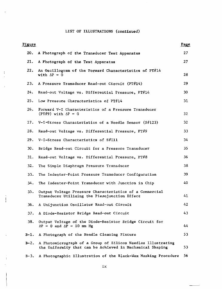
LIST OF ILLUSTRATIONS (continued)
Figure
20.
21.
22.
23.
24.
25.
26.
27.
28.
29.
30.
31.
32.
33.
34.
35.
36.
37.
38.
B-1.
B-2.
B-3.
A Photograph of the Transducer Test Apparatus
A Photograph of the Test Apparatus
An Oscillogram of the Forward Characteristics of PTC14 with AP = 0
A Pressure Transducer Read-out Circuit (PTtl4)
Read-out Voltage vs. Differential Pressure, PT#14
Low Pressure Characteristics of PT#14
Forward V-I Characteristics of a Pressure Transducer (PT89) with AP = 0
V-I-Stress Characteristics of a Needle Sensor (S11123)
Read-out Voltage vs. Differential Pressure, PTb9
V-I-Stress Characteristics of Sllll
Bridge Read-out Circuit for a Pressure Transducer
Read-out Voltage vs. Differential Pressure, PT#8
The Simple Diaphragm Pressure Transducer
The Indenter-Point Pressure Transducer Configuration
The Indenter-Point Transducer with Junction in Chip
Output Voltage Pressure Characteristics of a Commercial Transducer Utilizing the Piezojunction Effect
A Unijunction Oscillator Read-out Circuit
A Diode-Resistor Bridge Read-out Circuit
Output Voltage of the Diode-Resistor Bridge Circuit for AP = 0 and AP = 10 mm Hg
A Photograph of the Needle Cleaning Fixture
A Photomicrograph of a Group of Silicon Needles Illustrating the Uniformity that can be Achieved in Mechanical Shaping
Page
27
27
28
29
30
31
32
32
33
34
35
36
38
39
40
41
42
43
44
53
53
A Photographic Illustration of the Black-Wax Masking Procedure 56
ix
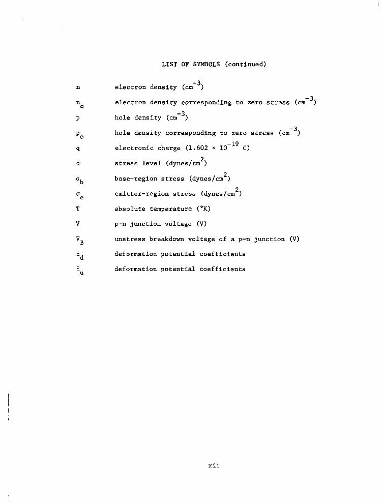
LIST OF SYMBOLS (continued)
n
n 0
P
U
U b
0 e T
V
vB
- I
U
electron density ( ~ m - ~ )
electron density corresponding to zero stress ( ~ m - ~ )
hole density (cm-j)
hole density corresponding to zero stress
electronic charge (1.602 X 10 C)
stress level (dynes/cm )
- 19
2
base-region stress (dynes/cm )
emitter-region stress (dynes/cm )
absolute temperature (OK)
p-n junction voltage (V)
unstress breakdown voltage of a p-n junction (VI
deformation potential coefficients
deformation potential coefficients
z
2
xii
A FEASIBILITY STUDY OF A MINIATURE SOLID-STATE
PRESSURE TRANSDUCER
By C. D. Parker R e s e a r c h T r i a n g l e I n s t i t u t e
SECTION I
INTRODUCTION
The o b j e c t i v e o f t h i s s t u d y w a s t o d e m o n s t r a t e t h e f e a s i b i l i t y o f u s i n g t h e p i e z o j u n c t i o n e f f e c t a s t h e s e n s o r y phenomenon i n a s o l i d - s t a t e pressure t ransducer . The p i e z o j u n c t i o n e f f e c t , i . e . , t h e s e n s i t i v i t y of t h e V-I c h a r a c t e r i s t i c s of a p-n j u n c t i o n t o stress, i s an extremely s e n s i t i v e mechanism and p o t e n t i a l l y p r o v i d e s f o r s i g n i f i c a n t improvements i n t h e t r a n s d u c e r a r t . The p i e z o j u n c t i o n e f f e c t o c c u r s a t h i g h stress
l e v e l s (a > lo9 dynes/cm2 i n s i l i c o n ) and i s cha rac t e r i zed by an expo- n e n t i a l i n c r e a s e i n m i n o r i t y carrier d e n s i t y a s stress is increased above t h e t h r e s h o l d l e v e l . The m i n o r i t y c a r r i e r d e n s i t y i s approximately l i n e a r l y r e l a t e d t o c u r r e n t i n a forward biased p-n junc t ion and an i n c r e a s e i n t h e m i n o r i t y c a r r i e r d e n s i t y c a n b e r e a d i l y d e t e c t e d i n t h e V-I c h a r a c t e r i s t i c s o f t h e j u n c t i o n . The exponent ia l re la t ionship be tween stress, minori ty carrier dens i ty and , consequent ly , forward cur ren t in a p-n j u n c t i o n make the p i ezo junc t ion phenomenon p a r t i c u l a r l y a t t r a c t i v e a s a stress transducing mechanism. Configurations which permit physical parameters such as p res su re and acce le ra t ion t o va ry t he stress app l i ed t o a p-n j u n c t i o n p o t e n t i a l l y p r o v i d e f o r a fami ly o f sens i t ive p iezo- junc t ion t ransducers .
Th i s i nves t iga t ion was a con t inua t ion of a p r e c e d i n g f e a s i b i l i t y s tudy and l a rge ly bu i ld s on t he r e su l t s o f t ha t e f fo r t (Re f . 1 ) . P r io r t o t h i s i n v e s t i g a t i o n , t h e s e n s i t i v i t y of p-n j u n c t i o n s t o stress had been demonstrated. The idea o f a s i l i c o n n e e d l e s e n s o r had been con- ceived as t h e s o l u t i o n t o numerous problems a s soc ia t ed w i th exp lo i t i ng t h e p i e z o j u n c t i o n phenomenon and t h e f e a s i b i l i t y o f f a b r i c a t i n g such a sensor demonst ra ted . Needle sensors had been fabr ica ted in to p ressure t r ansduce r s and u sed t o de t ec t changes i n d i f f e ren t i a l p re s su re . Seve ra l d e f i c i e n c i e s i n t h e n e e d l e s e n s o r were obvious. Few were fab r i ca t ed w i th d e s i r a b l e d i o d e c h a r a c t e r i s t i c s a n d c o n t a c t t o t h e d i f f u s e d t i p r e g i o n depended upon a p h y s i c a l c o n t a c t t o t h a t r e g i o n . A t t h e stress and cu r ren t levels r equ i r ed fo r s a t i s f ac to ry pe r fo rmance , t he phys i ca l con tac t is u n r e l i a b l e as a n e l e c t r i c a l c o n t a c t . I n o r d e r t o e l i m i n a t e t h e dependency on the phys ica l contac t be tween the needle t ip and the mater ia l against which i t is s t ressed ( the d iaphragm) ,severa l t echnica l p roblems had to b e s o l v e d . I n p a r t i c u l a r , a double window masking process was
e
needed t o p r o v i d e p o s i t i v e i s o l a t i o n of the j unc t ion and a good pass iva t ing ox ide was r e q u i r e d t o i n s u l a t e t h e b u l k s i l i c o n from t h e expanded aluminum con tac t .
S i l i c o n n e e d l e s e n s o r s w i t h d e s i r a b l e V-I-stress c h a r a c t e r i s t i c s have been fabr ica ted in to sens i t ive p ressure t ransducers which demonst ra te t h e f e a s i b i l i t y o f e x p l o i t i n g t h e p i e z o j u n c t i o n e f f e c t as a stress t rans- ducing mechanism. The f u l l p o t e n t i a l o f t h e p i e z o j u n c t i o n e f f e c t a n d e spec ia l ly o f t he s i l i con need le s enso r , however , has no t been demons t r a t ed . A l though p rocess ing p rocedures fo r f ab r i ca t ing s i l i con need le s enso r s evolved and were s i g n i f i c a n t l y r e f i n e d , a s u f f i c i e n t number of sensors f o r c a r r y i n g o u t t h e e x t e n s i v e e x p e r i m e n t a l p r o g r a m n e e d e d i n t h i s e f f o r t could not be produced. The e f f e c t s o f chang ing phys i ca l cha rac t e r i s t i c s o f t he s i l i con need le s enso r s such as p r i n c i p a l a x i s o r i e n t a t i o n , b u l k r e s i s t i v i t y and needle- t ip sharpness need to be experimental ly evaluated, and a s u f f i c i e n t number of good qua l i ty s enso r s p roduced t o p rov ide fo r ex tens ive parameter eva lua t ion exper iments in the p ressure t ransducers . Pressure t ransducer parameters such as diaphragm s i ze , t h i ckness and mater ia l ; bonding materials and over -pressure p ro tec t ive devices have no t been adequately evaluated due to the shortage of sensors . A technology fo r f ab r i ca t ing need le s enso r s has evo lved however , and t h e f e a s i b i l i t y of a piezojunct ion pressure t ransducer demonstrated.
2
SECTION I1
THEORETICAL CONSIDERATIONS - A SUMMARY
A comple t e t heo re t i ca l d i scuss ion of t h e p i e z o j u n c t i o n phenomenon i n s i l i c o n h a s b e e n p u b l i s h e d by Wortman, e t a l . , (Refs. 2-6). These d i scuss ions are summarized i n t h i s r e p o r t i n t h e i n t e r e s t of completeness.
Energy Band Considerat ions
The e lectr ical c h a r a c t e r i s t i c s of semiconductors and the piezo- j u n c t i o n phenomenon are conven ien t ly desc r ibed i n terms of the energy band s t r u c t u r e . S i l i c o n , a s i s t h e case f o r a l l semiconductors, has a forbidden energy region (energy gap) separat ing the valence energy levels (valence band) and the conduction energy levels (conduct ion band) . In momentum space (E-space) , t h e maximum v a l e n c e l e v e l s i n s i l i c o n o c c u r a t
= (000) and the minimum conduction levels o c c u r i n t h e < loo> d i r e c t i o n s .
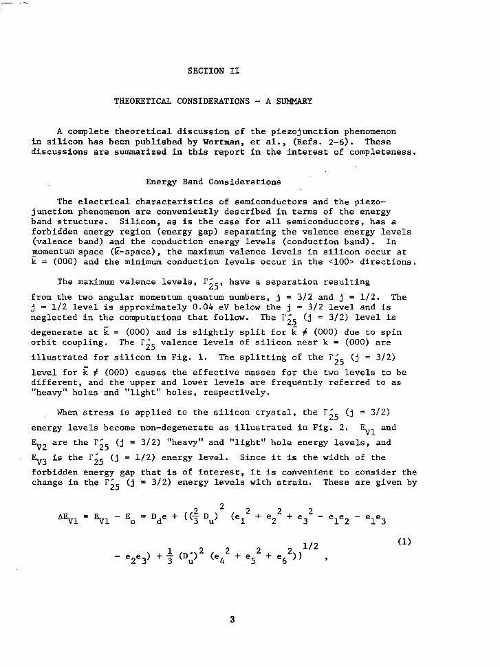
The maximum v a l e n c e l e v e l s , have a s e p a r a t i o n r e s u l t i n g 5 5 , from the two angular momentum quantum numbers, j = 312 and j = 1 / 2 . The j = 112 level is approximately 0.04 e V below the j = 3 /2 l e v e l and i s neg lec t ed i n t he computa t ions t ha t fo l low. The (j = 3 / 2 ) l e v e l is
d e g e n e r a t e a t = (000) and is s l i g h t l y s p l i t f o r k (000) due t o s p i n o rb i t coup l ing . The l";, valence levels of s i l i c o n near k = (000) a r e
i l l u s t r a t e d f o r s i l i c o n i n F i g . 1. The s p l i t t i n g of t h e r ' ( j = 3/2)
l e v e l f o r k # (000) causes t he e f f ec t ive masses fo r t he two l e v e l s t o b e d i f f e r e n t , and the upper and lower l eve ls a re f requent ly re fe r red to as "heavy" holes and "l ight" holes , r e spec t ive ly .
25
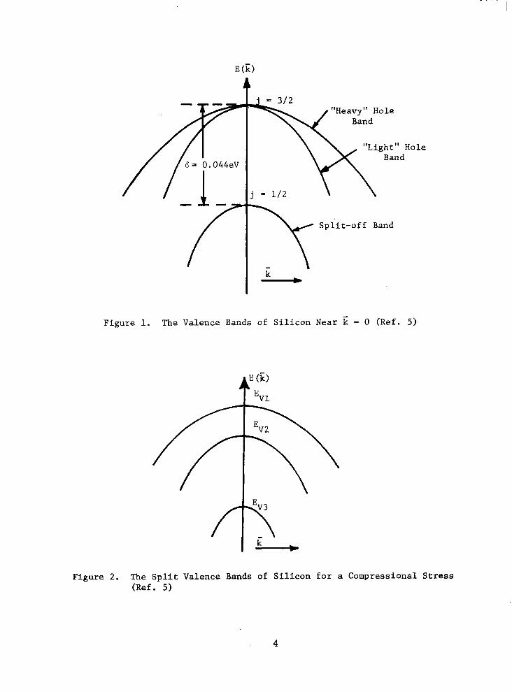
When stress i s a p p l i e d t o t h e s i l i c o n c r y s t a l , t h e r i 5 ( j = 3/2)
energy levels become non-degenerate as i l l u s t r a t e d i n F i g . 2. EV1 and
EV2 are the r' ( j = 3/2) "heavy" and "l ight" hole energy levels, and 25 . EV3 is t h e r i 5 ( j = 1/2) energy level . Since i t . is the w id th of t he
forbidden energy gap t h a t is of i n t e r e s t , i t is convenient to cons ider the change i n t h e r;, (j = 3/2) energy levels wi th s t r a in . These are given by
2 2 BEVl EV1 - Eo = D d e + 1(7 D ~ > (el2 + e 2 + e3 2 - ele2 - ele3
2
3
= 3 / 2 Heavy'' Hole
"Light" Hole Band
6 = 0.044eV
j = 1 / 2
-h/ S p l i t - o f f Band
F i g u r e 1. The Valence Bands of S i l i c o n Near E = 0 ( R e f . 5)
F igu re 2. The S p l i t V a l e n c e Bands of S i l i c o n f o r a Compress iona l S t r e s s ( R e f . 5)
4
and
AEV2 = EV2 - Eo = Dde - { ( ? j ~ ~ ) ~ ( e : + e 2 + e 2 3 2 - e e 1 2 - e e 1 3
where the D ' s are t h e d e f o r m a t i o n p o t e n t i a l c o e f f i c i e n t s , t h e ei's
are t h e e n g i n e e r i n g s t r a i n components along the crystal axes (see Appendix A ) , and
e = e l + e + e 2 3 - (3)
More s p e c i f i c a l l y , Dd is t h e e n e r g y l e v e l s h i f t p e r u n i t d i l a t i o n of t h e
r;5 ( j = 312) band edge, D is p r o p o r t i o n a l t o t h e s p l i t t i n g of the band
edge induced by u n i a x i a l s h e a r s t r a i n a l o n g t h e [ l o o ] a x i s , and D L is
p ropor t iona l t o t he band edge sp l i t t i ng i nduced by u n i a x i a l s h e a r s t r a i n a long the [ 1111 a x i s . E is the uns t r a ined I" ( j = 312) energy level (Refs. 2, 5 ) . 0 25
U
Strain a lso induces changes in the conduct ion bands, and changes in the conduction band minima are of equal importance with changes i n t h e valence band maximum. S i l i c o n h a s s i x c o n d u c t i o n band minima loca ted a l o n g t h e p r i n c i p a l c r y s t a l a x e s . S i n c e t h e s e minima change i n p a i r s , i . e . , s ince one cannot dis t inguish between the conduct ion band minima
loca ted a long the [ loo] and [io01 axes, only three conduction band minima need be considered, EC1, EC2 and EC3. Changes in t hese conduc t ion
band minima i n t h e stress reg ion of i n t e r e s t are given by (Refs. 2 , 5)
AEC1 = Ed e + Eu el ,
AEC2 = Ed e + C e -u 2 '
AEC3 = Z d e + ' - -u e3 , where the E's are, t h e d e f o r m a t i o n p o t e n t i a l c o e f f i c i e n t s .
Changes in the valence band and conduction band maxima and minima energy levels g ives rise t o a change i n t h e carrier c o n c e n t r a t i o n s i n t h e conduct ion and va lence bands . In s i l i con , for example , the dens i ty of e lec t rons assoc ia ted wi th the s ix conduct ion band minima is given by
2nkT
TI
31 2 n = 2 ~ 3 - 1 {mCl3I2 exp[-( kT 3'2 exp[-( kT
EC2 - EF)
where E = the Fermi energy level, and F
ci m = t h e e f f e c t i v e e l e c t r o n masses a s s o c i a t e d w i t h t h e e n e r g y minima.
Under t h e a p p l i c a t i o n of stress, Eq. (5) c a n b e w r i t t e n as
where n = uns t r e s sed e l ec t ron dens i ty , and
AEF = change i n t h e Fermi energy.
0
S i m i l a r l y , t h e carrier concen t r a t ion a s soc ia t ed w i th t he va l ence band maxima is given by
where "vi = e f f e c t i v e masses a s soc ia t ed w i th t he va l ence band maxima (E ). I n Eq. (7), t h e rG5 ( j = 1/2) energy leve l has been neglec ted . If t h e
small difference between yl and mv2 i s a l s o n e g l e c t e d , a good approxina-
t i o n f o r s i l i c o n , Eq. (7 ) c a n b e w r i t t e n f o r s t r e s s e d c o n d i t i o n s as
V i
P O AEF AEV1 AEV2 p = - exp (- 2 "> [exp (F) + exp (-zT-) 1 , kT
where p = the ho le concent ra t ion wi th no stress. 0
AEF The exp(- F) terms i n Eqs. ( 6 ) and (8) can be eva lua ted by s e t t i n g
the ma jo r i ty ca r r i e r dens i ty equa l t o t he impur i ty dens i ty and a s suming the i on iza t ion ene rgy t o be i ndependen t of stress. Consequently, the hole dens i ty remains cons tan t in p - type material, for example, and
AEF 1 A E V 1 AEV2 kT kT exp (-1 = 7 [exp (-1 + exp 1 .
6
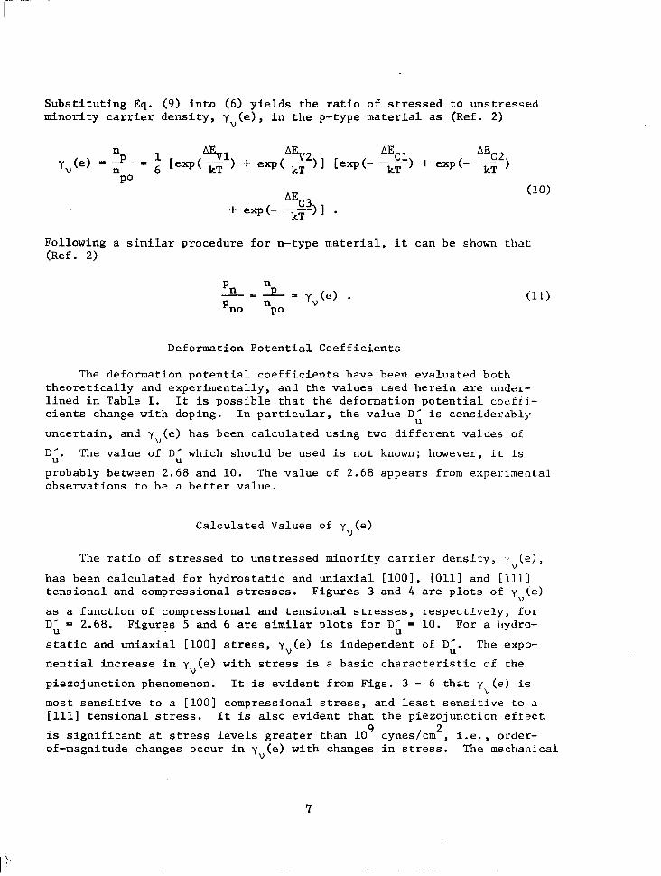
S u b s t i t u t i n g Eq. ( 9 ) i n t o (6) y i e l d s t h e r a t i o o f s t r e s s e d t o u n s t r e s s e d minor i ty carrier d e n s i t y , y ( e ) , i n t h e p - t y p e material as (Ref. 2)
V
Following a similar procedure for n- type material, i t can be shown that (Ref. 2)
Deformat ion Poten t ia l Coef f ic ien ts
The deformat ion po ten t ia l coef f ic ien ts have been eva lua ted bo th t h e o r e t i c a l l y and experimental ly , and the values used herein are undar- l i n e d i n T a b l e I. I t is p o s s i b l e t h a t t h e d e f o r m a t i o n p o t e n t i a l cozfij~- c i e n t s change with doping. In p a r t i c u l a r , t h e v a l u e D’ i s cons iderably
unce r t a in , and y (e) has been calculated using two d i f f e r e n t v a l u e s of
D’. The value of D‘ which should be used i s not known; however, i t is
probably between 2.68 and 10. The va lue of 2 .68 appears from experiaenLa1 obse rva t ions t o be a b e t t e r v a l u e .
U
V
U U
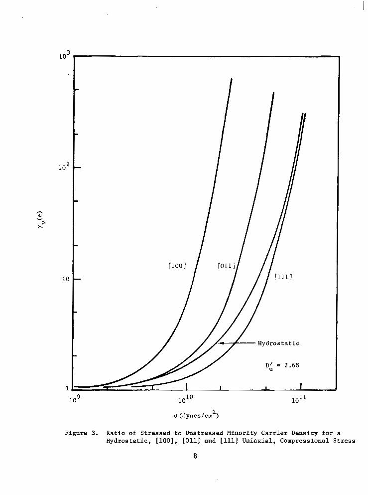
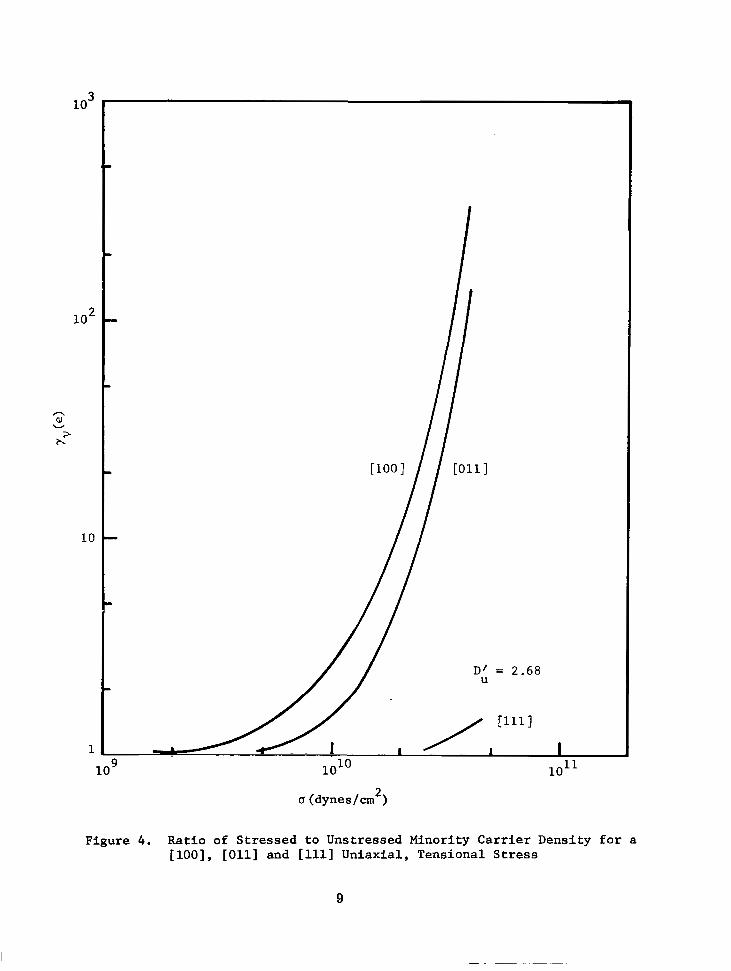
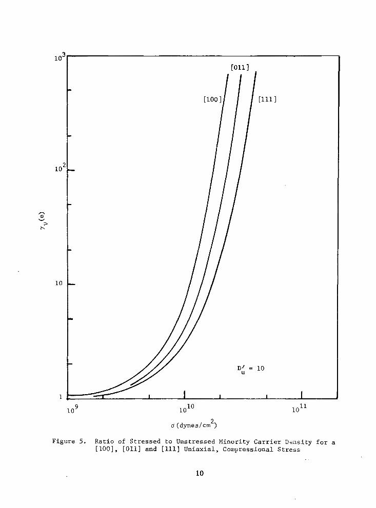
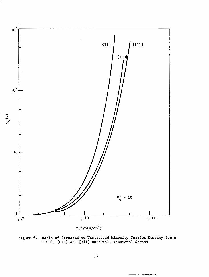
Calculated Values of yv(e)
The r a t i o of s t r e s s e d t o u n s t r e s s e d m i n o r i t y c a r r i e r d e n s i t y , ; ( e ) , V
has been ca lcu la ted for hydros ta t ic and un iax ia l [ l o o ] , [Oll] and [ l . l . l j tensional and compressional stresses. Figures 3 and 4 are p l o t s of y (e)
a s a func t ion of compressional and tensional stresses, r e s p e c t i v e l y , for D’ = 2.68. Figures 5 and 6 are similar p l o t s f o r D’ = 10. For a Ilydro-
s t a t i c and u n i a x i a l [ loo] stress, y (e ) is independent of D’. The expo-
n e n t i a l i n c r e a s e i n y ( e ) w i th stress is a b a s i c c h a r a c t e r i s t i c of the
p iezojunct ion phenomenon. It is evident from Figs. 3 - 6 t h a t - fv (e ) is
most s e n s i t i v e t o a [ l o o ] compressional stress, and least s e n s i t i v e to a [111] t ens iona l stress. It is a l s o e v i d e n t t h a t t h e p i e z o j u n c t i o n e f f e c t
is s i g n i f i c a n t a t stress levels g rea t e r t han lo9 dynes/cm , i . e . , order- of-magnitude changes occur i n y (e ) wi th changes in stress. The mechanical
U U
V U
V
2
V
7
n aJ W
> h
l o 2
10
1
l o 9 1o1O l o l l
Figure 3. Ratio of Stressed to Unstressed Minority Carrier Density for a Hydrostatic, [loo], [Oll] and [lll] Uniaxial, Compressional Stress
8
l o 2
h
v al > h
10
1
Figure 4. Ratio of Stressed to Unstressed Minority Carrier Density for a [loo], [Oll] and [lll] Uniaxial, Tensional Stress
9
10-
10'
n al
W
b >
10
1
l o 9 1o1O
IS (dynes/cm 2 )
l o l l
Figure 5. Ratio of Stressed to Unstressed Minority Carrier ' J ens i ty for a [lOO], [Oll] and [lll] Uniaxial, Compressional Stress
10
lo2
n
W al > b
10
1
D' = 10 u
u (dynes/cmL)
Figure 6. Ratio of Stressed to Unstressed Minority Carrier Density for a [loo], [Oll] and [ill] Uniaxial, Tensional Stress
11
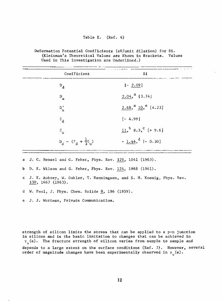
Table I. (Ref. 4)
Deformation Potential Coefficients (eV/unit dilation) for Si. (Kleinman's Theoretical Values are Shown in Brackets. Values Used in This Investigation are Underlined.)
Si
Dd
DU
D;
[ - 2 .091
2.04, [3.741 a
2.68, x, L4.231 a e
[- 4.991
11 8.3, [+ 9.61 C - 9
- 1.44, [ - 0.301 d
a J. C. Hensel and G. Feher, Phys. Rev. 129, 1041 (1963).
b D. K. Wilson and G. Feher, Phys. Rev. 124, 1968 (1961).
c J. E. Aubrey, W. Gubler, T. Henningsen, and S. H. Koenig, Phys. Rev.
-
130, 1667 (1963).
d W. Paul, J. Phys. Chem. Solids 8, 196 (1959). e J. J. Wortman, Private Communication.
strength of silicon limits the stress that can be applied to a p-n junction in silicon and is the basic limitation to changes that can be achieved in y,(e). The fracture strength of silicon varies from sample to sample and
depends to a large extent on the surface conditions (Ref. 7). However, several order of magnitude changes have been experimentally observed in y (e).
V
12
Effec t o f S t r e s s on p-n J u n c t i o n C h a r a c t e r i s t i c s
The e f f e c t o f stress on p-n j u n c t i o n c h a r a c t e r i s t i c s h a s b e e n d e s c r i b e d i n terms of y,(e) (Refs. 3, 5). Changes i n o t h e r p a r a m e t e r s
' are assumed t o b e n e g l i g i b l e as compared with the exponent ia l change of
y,(e) with stress above lo9 dynes/cm . This mode l a l so neg lec t s t he
cont r ibu t ion of sur face genera t ion- recombina t ion cur ren ts .
2
The t o t a l c u r r e n t ( I T ) i n p-n j u n c t i o n s is t h e sum o f t h e i d e a l
cu r ren t (I ) and the generat ion-recombinat ion currents (I ). T R
I T = I I + I R .
For forward biased condi t ions, the bulk generat ion-recombinat ion current i s given approximately by (Ref. 3)
a Y.. (e) [exp (qV/kT)-l]
and t h e i d e a l c u r r e n t is given by
such that Eq. (12) becomes (Ref. 3)
The e f f e c t of s t r e s s i n g o n l y p a r t o f t h e t o t a l j u n c t i o n a r e a i s accounted for by cons ide r ing t ha t t he t o t a l d iode cons i s t s of two d i o d e s i n p a r a l l e l , i . e . , (1) a s t r e s sed d iode , and (2) an unstressed diode. I f t h e t o t a l a r e a i s A , for example, and the s t ressed area is A then Eq. (14) becomes (Ref. 3) S '
I n
It is of i n t e r e s t h e r e d i f f e r e n t b i a s c o n d i t i o n s . approximately
t o c o n s i d e r t h e p-n junc t ion cur ren t under For large forward biases , Eq. (15) is
13
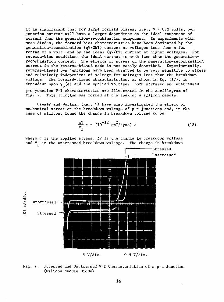
It is s i g n i f i c a n t t h a t f o r l a r g e f o r w a r d b i a s e s , i .e . , V > 0.3 v o l t s , p-n j u n c t i o n c u r r e n t w i l l have a la rger dependence on the idea l component of current than the generat ion-recombinat ion component. In exper iments wi th mesa diodes, the forward-bias character is t ics have been dominated by t h e generation-recombination (qV/2kT) c u r r e n t a t vo l t ages less than a few ten ths o f a vo l t , and by t h e i d e a l (qV/kT) c u r r e n t a t h igher vo l tages . For r e v e r s e - b i a s c o n d i t i o n s t h e i d e a l c u r r e n t i s much less than the genera t ion- recombinat ion current . The e f f e c t s of stress on the generat ion-recombinat ion c u r r e n t i n t h e r e v e r s e - b i a s e d mode i s no t ea s i ly desc r ibed . Expe r imen ta l ly , reverse-biased p-n junc t ions have been obse rved t o be ve ry s ens i t i ve t o stress and re la t ive ly independent o f vo l tage for vo l tages less than t he breakdown vo l t age . The fo rward -b ia sed cha rac t e r i s t i c s , as shown i n E q . (17), is dependent upon y (e ) and the appl ied vo l tage . Both s t ressed and uns t ressed
p-n j u n c t i o n V-I c h a r a c t e r i s t i c s are i l l u s t r a t e d i n t h e o s c i l l o g r a m o f F ig . 7. Th i s j unc t ion was formed a t t h e a p e x o f a s i l i c o n n e e d l e .
V
Hauser and Wortman (Ref. 4 ) h a v e a l s o i n v e s t i g a t e d t h e e f f e c t o f mechanical stress on t h e breakdown vol tage of p-n j u n c t i o n s a n d , i n t h e case of s i l icon, found the change in breakdown vol tage to be
- = - cm2/dyne) o AV
vB
where (5 i s the app l i ed stress, AV is the change in breakdown voltage and V is t h e u n s t r e s s e d breakdown vo l t age . The change i n breakdown B
I, S t r e s s e d Unstressed
5 V/div. 0.5 V/div.
F ig . 7 . S t r e s s e d and Unstressed V - I C h a r a c t e r i s t i c s o f a p-n Junct ion (Silicon Needle Diode)
14
vo l t age is also independent of or ientat ion. Since the breakdown vol tage is a l i n e a r f u n c t i o n of stress whereas j unc t ion cu r ren t is an exponent ia l f u n c t i o n of stress, t h e l a t te r mode of ope ra t ion is p o t e n t i a l l y a more s e n s i t i v e t r a n s d u c i n g mechanism. However, breakdown vo l t age i s less sens i t i ve t o t empera tu re changes t han j unc t ion cu r ren t s , and t h i s mode of ope ra t ion may have advantages i n some a p p l i c a t i o n s .
The e f f e c t s of stress on more complex s i l i c o n p-n j u n c t i o n s t r u c t u r e s is a l s o of i n t e r e s t . I n v e s t i g a t i o n s of t h e e f f e c t s of stress upon tran- s i s t o r c h a r a c t e r i s t i c s a n d p-n-p-n switches have been performed (Ref. 2) . I f bo th s ides of t h e e m i t t e r - b a s e j u n c t i o n a r e s t r e s s e d , t h e b a s e a n d c o l l e c t o r c u r r e n t s are changed several o rde r s of magnitude f o r s m a l l c h a n g e s i n stress above the threshold value, and current gain is n o t a f f e c t e d . I f o n l y t h e emitter s i d e of t h e j u n c t i o n is s t r e s s e d (a >> a ) the base cur ren t in -
creases orders of magnitude with stress w h i l e t h e c o l l e c t o r c u r r e n t r e m a i n s unchanged. Consequently, gain i s reduced by s t r e s s i n g t h e emitter s i d e o f t he base -emi t t e r j unc t ion . I f on ly t he base s ide o f t he j unc t ion is s t r e s s e d (a << Ob), t he base and co l l ec to r cu r ren t s r ema in approx ima te ly t h e same.
e b
e
The e f f e c t of stress on p-n-p-n d iodes has a l so been i nves t iga t ed and concluded t o b e a complex funct ion of numerous va r i ab le s , e .g . , t he uniformity and l o c a t i o n of t he app l i ed stress. The switching vol tage can inc rease o r dec rease w i th an i nc reas ing stress depending upon these various f a c t o r s . The changes i n s w i t c h i n g v o l t a g e w i t h stress can be very l a rge , however, and the four-layer configuration is a promising t ransducer conf igura t ion .
15
SECTION I11
PRESSURE TRANSDUCER CONFIGURATION
I n o r d e r t o u t i l i z e t h e stress s e n s i t i v i t y of a p-n j u n c t i o n as t h e sensory phenomenon i n a p res su re t r ansduce r , a t r ansduce r con f igu ra t ion i s r e q u i r e d i n which pressure var ia t ions cause a v a r i a n c e i n t h e stress app l i ed t o t h e j u n c t i o n . Of the va r ious t r ansduce r con f igu ra t ions wh ich have been cons ide red , t he s i l i con need le s enso r is concluded to be the most advantageous. The concept of the needle sensor evolved as a s o l u t i o n t o several p rob lems a s soc ia t ed w i th exp lo i t i ng t he p i ezo junc t ion phenom- enon in t r ansduce r s . Concep tua l ly , t he re are no l i m i t a t i o n s t o t h e q u a l i t y of a p-n j u n c t i o n f a b r i c a t e d i n t h e n e e d l e c o n f i g u r a t i o n , t h e j u n c t i o n area can be made small and alignment problems are non-exis tent . The fundamental disadvantages of the needle sensor are a l s o c h a r a c t e r i s t i c o f e v e r y o t h e r workable configurat ion.
The Silicon Needle Sensor Configuration
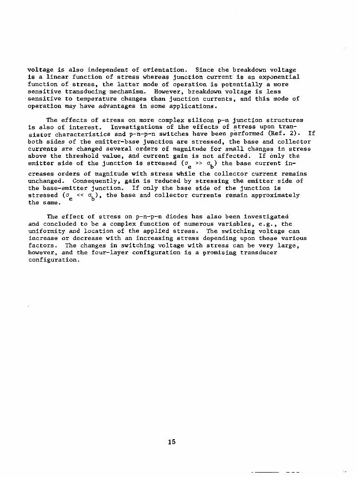
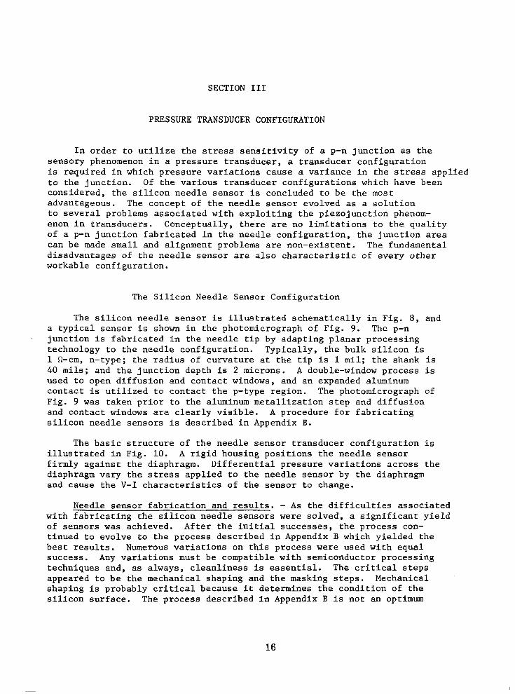
The s i l i c o n n e e d l e s e n s o r i s i l l u s t r a t e d s c h e m a t i c a l l y i n F i g . 8, and a t y p i c a l s e n s o r is shown in the photomicrograph of Fig. 9. The p-n j u n c t i o n i s f a b r i c a t e d i n t h e n e e d l e t i p by adapt ing p lanar p rocess ing t echno logy t o t he need le con f igu ra t ion . Typ ica l ly , t he bu lk s i l i con is 1 Q-cm, n- type ; the rad ius of cu rva tu re a t t h e t i p i s 1 m i l ; the shank i s 40 mils; and the junct ion depth is 2 microns. A double-window process i s used to open diffusion and contact windows, and an expanded aluminum con tac t i s u t i l i zed t o con tac t t he p - type r eg ion . The photomicrograph of Fig. 9 was t a k e n p r i o r t o t h e aluminum m e t a l l i z a t i o n s t e p and d i f fus ion and contact windows are c l e a r l y v i s i b l e . A p rocedure fo r f ab r i ca t ing s i l i c o n n e e d l e s e n s o r s is descr ibed in Appendix B.
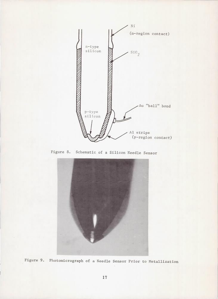
The b a s i c s t r u c t u r e o f t h e n e e d l e s e n s o r t r a n s d u c e r c o n f i g u r a t i o n i s i l l u s t r a t e d i n F i g . 1 0 . A r ig id hous ing pos i t i ons t he need le s enso r f i rmly aga ins t t he d i aphragm. D i f f e ren t i a l p re s su re va r i a t ions ac ross t he diaphragm vary the stress appl ied . to the needle sensor by the diaphragm and cause the V - I c h a r a c t e r i s t i c s o f t h e s e n s o r t o c h a n g e .
Needle sensor fabr ica t ion and resu l t s . - A s t h e d i f f i c u l t i e s a s s o c i a t e d w i t h f a b r i c a t i n g t h e s i l i c o n n e e d l e s e n s o r s were so lved , a s i g n i f i c a n t y i e l d of sensors was a c h i e v e d . A f t e r t h e i n i t i a l s u c c e s s e s , t h e p r o c e s s con- t i nued t o evo lve t o t he p rocess desc r ibed i n Append ix B which yielded the b e s t r e s u l t s . Numerous v a r i a t i o n s on t h i s p r o c e s s were used wi th equal success . Any variations must be compatible with semiconductor processing techniques and, as a lways , c leanl iness i s e s s e n t i a l . The c r i t i c a l s t e p s appeared to be the mechanical shaping and the masking s teps . Mechanical shaping i s p r o b a b l y c r i t i c a l b e c a u s e i t determines the condi t ion of the s i l i c o n s u r f a c e . The process descr ibed in Appendix B is not an optimum
16
n-type si l icon
Ni
(n-region contact)
Au "ball" bond
Ai stripe (p-region contact)
Figure 8. Schematic of a Silicon Needle Sensor
Figure 9. Photomicrograph of a Needle Sensor Prior to Metallization
17
Needle Sensor
Figure 10. An I l l u s t r a t i o n of t h e Needle Sensor Transducer Configuration
p rocess bu t one t ha t y i e lded cons i s t en t ly good r e s u l t s . I t i s probable t h a t f u r t h e r improvements are needed i n o r d e r t o r e a l i z e t h e f u l l p o t e n t i a l of s i l i c o n n e e d l e s e n s o r s . Some o f t h e b e s t o f the needle sensors are descr ibed in the fo l lowing paragraphs and f igures .
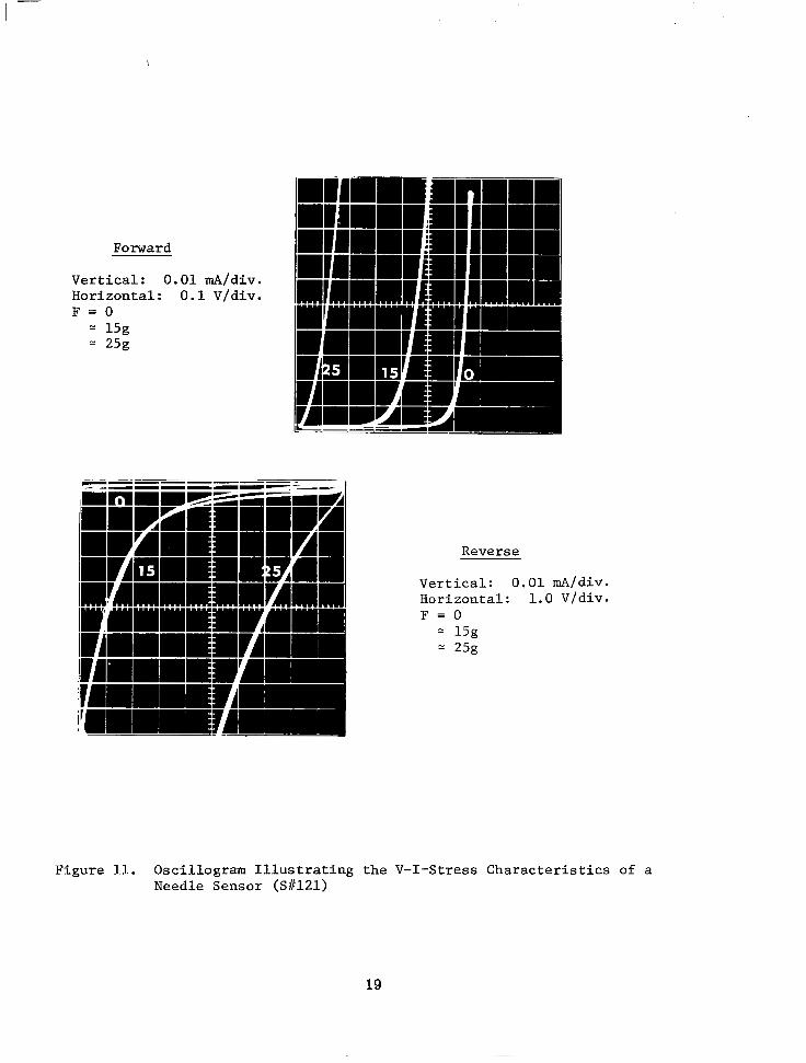
A u n i t w i t h e x c e l l e n t V - I c h a r a c t e r i s t i c s i s i l l u s t r a t e d i n t h e osci l lograms of Fig. 11. In t he fo rward cha rac t e r i s t i c s , t he t h ree cu rves c o r r e s p o n d t o z e r o f o r c e a g a i n s t t h e t i p of t he need le , a 15g force and 25g fo rce . (The gram f o r c e s are approximate, e .g . , 5 10 percenc) . Changes i n t h e V-I c h a r a c t e r i s t i c s o f t h i s s e w o r as t h e f o r c e i s incrzased tend t a b e i d e a l , i.e., t h e c h a r a c t e r i s t i c s move ho r i zon ta l ly ac ross t he s cope . The r e v e r s e c h a r a c t e r i s t i c s a l s o c o r r e s p o n d t o z e r o , 15g and 25g forces . The zero stress curve shows the s enso r t o be an exce l l en t d iode . Gene ra l ly Lhe r e v e r s e c h a r a c t e r i s t i c s t e n d t o b e more leaky. This sensor (SF121) was evc -n tua l ly f ab r i ca t ed i n to a p res su re t r ansduce r (PT#14) wi th exce l l en t r e s u l t s .
A shadow p r o f i l e o f S # l 2 l is shown in the photomicrograph of Fig. 12. Successive 90" r o t a t i o n s of t he s enso r showed a n i d e n t i c a l p r o f i l e . The r a d i u s of cu rva tu re on t he t i p is approximately 0.5 mils and the inc luded so l id angle approximate ly 90" . The s o l i d a n g l e was eventua l ly s tandard ized t o 60" a l though un i t s w i th ang le s less than 45' were successfu l ly p rocessed . E f f o r t s t o i n c r e a s e t h e s h a r p n e s s o f t h e t i p , i . e . , r educe t he r ad ius of curva ture , were not comple te ly successfu l .
18
I -
I
Forward
Vertical: 0.01 mA/div. Horizontal: 0.1 V/div. F = O
15g = 25g
Reverse
Vertical: 0.01 mA/div. Horizontal: 1.0 V/div. F = O
= 15g = 25g
Figure 11. Oscillogram Illustrating the V-I-Stress Characteristics of a Needle Sensor (S#121)
19
2 3 4 5
11111111) ) I II If I II 1111 lIi,,",1
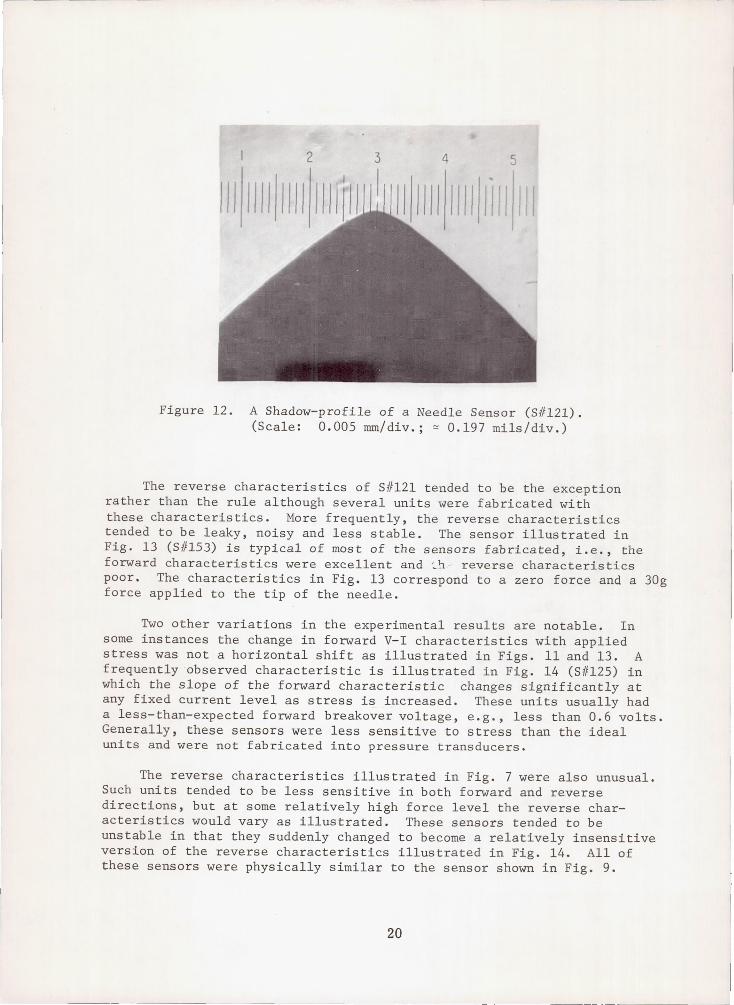
Figure 12. A Shadow-profile of a Needle Sensor (5#121). (Scale: 0.005 rnm/div.; ~ 0.197 mils/div.)
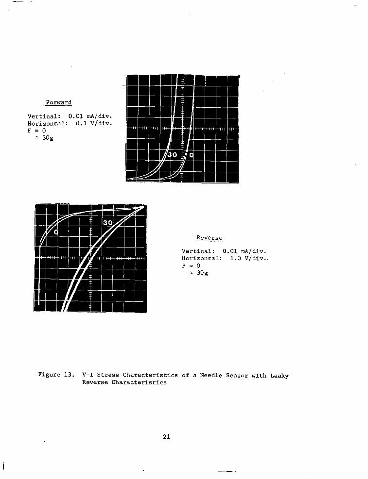
The reverse characteristics of 5#121 tended to be the exception rather than the rule although several units were fabricated with these characteristics. More frequently, the reverse characteristics tended to be leaky, noisy and less stable. The sensor illustrated in Fig. 13 (5#153) is typical of most of the sensors fabricated, i.e., the forward characteristics were excellent and -:..1:J. - reverse characteristics poor. The characteristics in Fig. 13 correspond to a zero force and a 30g force applied to the tip of the needle.
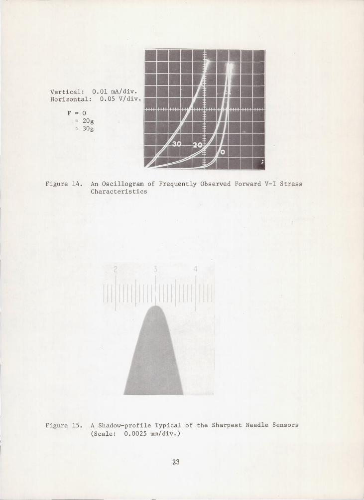
Two other variations in the experimental results are notable. In some instances the change in forward V-I characteristics with applied stress was not a horizontal shift as illustrated in Figs. 11 and 13. A frequently observed characteristic is illustrated in Fig. 14 (5#125) in which the slope of the forward characteristic changes significantly at any fixed current level as stress is increased. These units usually had a less-than-expected forward breakover voltage, e.g., less than 0.6 volts. Generally, these sensors were less sensitive to stress than the ideal units and were not fabricated into pressure transducers.
The reverse characteristics illustrated in Fig. 7 were also unusual. Such units tended to be less sensitive in both forward and reverse directions, but at some relatively high force level the reverse characteristics would vary as illustrated. These sensors tended to be unstable in that they suddenly changed to become a relatively insensitive version of the reverse characteristics illustrated in Fig. 14. All of these sensors were physically similar to the sensor shown in Fig. 9.
20
----------------------------- -------
”
Forward
Vertical: 0.01 mA/div. Horizontal : 0 .1 V/div. F = O
30g
Figure 13. V-I Stress C h a r a c t e r i s t i c s of a Needle Sensor with Leaky Rever se Cha rac t e r i s t i c s
21
An o b v i o u s a p p r o a c h t o i n c r e a s i n g t h e s e n s i t i v i t y a c h i e v e d w i t h i d e a l sensors such as S11121 w a s t o i n c r e a s e t h e s h a r p n e s s o f t h e s e n s o r i t se l f . The mechanical shaping process was m o d i f i e d t o y i e l d s h a r p e r p o i n t s s u c h a s t h o s e i l l u s t r a t e d i n F i g . 1 5 . I n t h i s case, t h e r a d i u s of cu rva tu re is 0 . 2 mils and t he i nc luded so l id ang le is 30". These un i t s were r e a d i l y fabr ica ted th rough the mechanica l shaping s teps , bu t the p rocessed sensors were unsa t i s f ac to ry . Op t i ca l examina t ion of these s enso r s showed c l e a r l y de f ined d i f fus ion and con tac t windows, and no apparent reason for the lack of success . T i m e permi t ted on ly a l i m i t e d number of t hese sha rpe r need le s to be p rocessed and i t is p r o b a b l y t h a t a c o n t i n u e d e f f o r t would even tua l ly be successfu l .
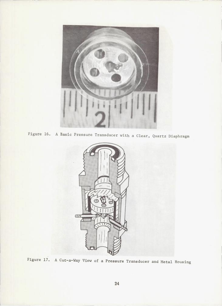
P re s su re t r ansduce r f ab r i ca t ion . - Most of t h e t r a n s d u c e r s f a b r i c a t e d d u r i n g t h i s s t u d y were b a s i c a l l y as i l l u s t r a t e d i n F i g . 10. Figure 16 i s a photograph of a bas ic t ransducer looking th rough the clear, q u a r t z diaphragm in to t he s enso r - s ide p re s su re po r t . Four ven t s are i n e v i d e n c e , and the sensor extends through a c e n t e r h o l e t o t h e rear of the t ransducer . Epoxy bonds a re u sed t h roughou t t he un i t . P re s su re va r i a t ions ac ross t he quartz diaphragm vary the stress on the s enso r . All of the t ransducers t o b e d e s c r i b e d are similar t o t h i s i l l u s t r a t i o n . The need le s enso r s have been improved and the i r shapes a l t e r ed , phys i ca l d imens ions have been changed and diaphragm materials have changed. The assembly of a t r ansduce r such as i l l u s t r a t e d i n F i g . 16 is b a s i c a l l y as fo l lows: the hous ing is completely assembled except for the needle sensor, and supported by placing the diaphragm face-down on a sho r t p i ece o f t ub ing s imi l a r t o t he tub ing u sed t o f ab r i ca t e t he hous ing . The needle sensor is he ld by a pin- v i c e i n a micro-manipulator , posi t ioned over the center hole and lowered s o t h e s e n s o r t i p is i n s i d e t h e center ho le . Epoxy is a p p l i e d t o t h e sensor shank and the sensor i s l o w e r e d u n t i l t h e t i p contacts the diaphragm and i s su i t ab ly s t r e s sed . Eve ry th ing i s h e l d r i g i d l y u n t i l t h e epoxy bond between the sensor and housing cures. The V - I c h a r a c t e r i s t i c s of the sensor a re moni tored wi th a curve tracer throughout the assembly. The gold wire bonded t o t h e expanded aluminum con tac t t o t he p - r eg ion i s fed through the center hole with the sensor and is a c c e s s i b l e a t t h e b a c k of the housing .
An e a r l i e r p r a c t i c e was t o fill an en la rged cen te r ho le w i th epoxy and d r i l l a h o l e i n t h e epoxy f o r t h e s e n s o r . Th i s p rac t i ce p roved t o be unnecessary. The t ransducer shown i n F i g . 16 was a s sembled t h i s way.
The b a s i c t r a n s d u c e r i l l u s t r a t e d i n F i g s . 1 0 a n d 1 6 was e n c l o s e d i n a metal h o u s i n g t o f a c i l i t a i :: handl ing and labora tory t es t ing . The completed transducer is shown s c h e m a t i c a l l y i n t h e cut-a-way drawing of Fig. 1 7 . Test appara tus was des igned to be compat ib le wi th th i s hous ing and i t was used fo r most transducers. A c o n d u c t i v e s i l v e r p a s t e , DuPont type 6730, was used to connec t go ld wires t o t h e back of the sensor shank and t h e metal feed-through ports. The end f i t t i n g s on the hous ing a r e s tock items. A photograph of a completed transducer i s shown i n F i g . 18.
22
Vertical: 0.01 mA/div. Horizontal: 0.05 V/div.
F 0 '" 20g '" 30g
;;;;
-=
'.4 -- ,,;:4
~ r.i
~ I~!:ii~
II 'J/ I ~
-;,
r •• ,j I·
, J '. ,
~
:
'"
~ ~r. I~ 0 . .... !Ij I
Figure 14. An Oscillogram of Frequently Observed Forward V-I Stress Characteristics
Figure 15. A Shadow-profile Typical of the Sharpest Needle Sensors (Scale: 0.0025 mm/div.)
23
J
,--- --
Figure 16. A Basic Pressure Transducer with a Clear, Quartz Diaphragm
Figure 17. A Cut-a-Way View of a Pressure Transducer and Metal Rousing
24
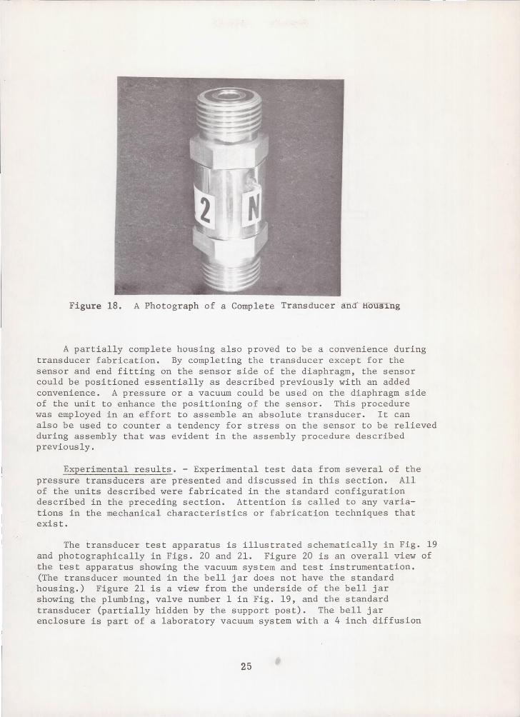
Figure 18. A Photograph of a Complete Transducer ana Hous1ng
A partially complete housing also proved to be a convenience during transducer fabrication. By completing the transducer except for the sensor and end fitting on the sensor side of the diaphragm, the sensor could be positioned essentially as described previously with an added convenience. A pressure or a vacuum could be used on the diaphragm side of the unit to enhance the positioning of the sensor. This procedure was employed in an effort to assemble an absolute transducer. It can also be used to counter a tendency for stress on the sensor to be relieved during assembly that was evident in the assembly procedure described previously.
Experimental results. - Experimental test data from several of the pressure transducers are presented and discussed in this section. All of the units described were fabricated in the standard configuration described in the preceding section. Attention is called to any variations in the mechanical characteristics or fabrication techniques that exist.
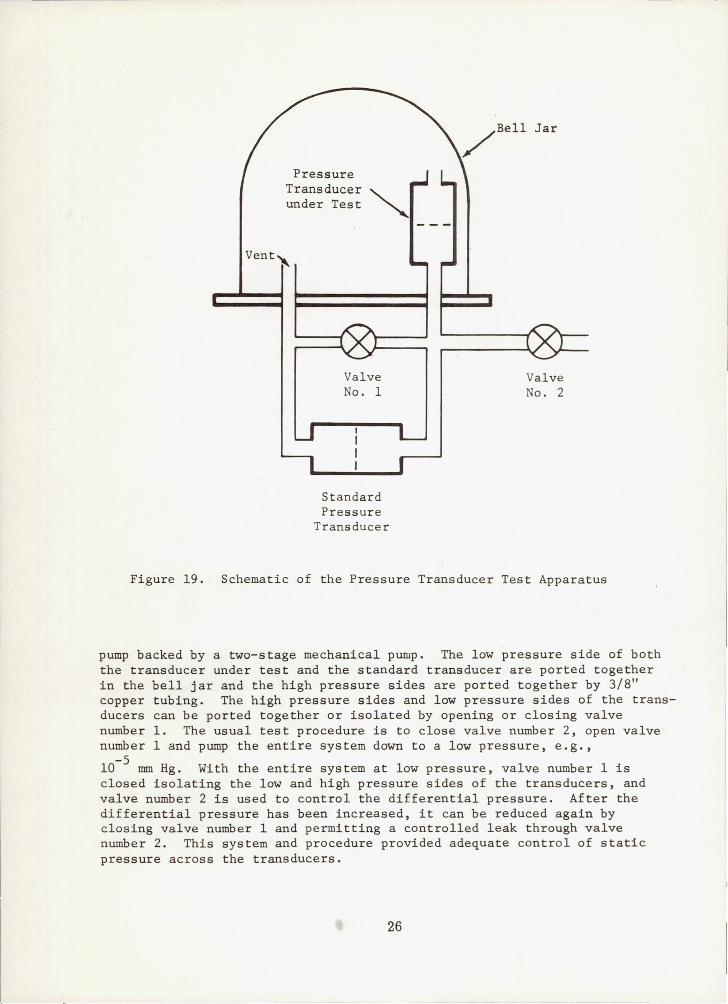
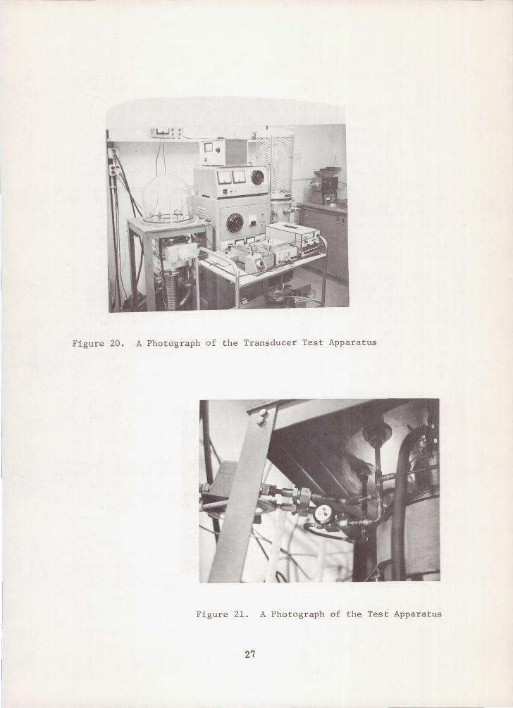
The transducer test apparatus is illustrated schematically in Fig. 19 and photographically in Figs. 20 and 21. Figure 20 is an overall view of the test apparatus showing the vacuum system and test instrumentation. (The transducer mounted in the bell jar does not have the standard housing.) Figure 21 is a view from the underside of the bell jar showing the plumbing, valve number 1 in Fig. 19, and the standard transducer (partially hidden by the support post). The bell jar enclosure is part of a laboratory vacuum system with a 4 inch diffusion
25
Pressure Transducer under Test
Vent~
Valve No. 1
Standard Pressure
Transducer
Valve No. 2
Figure 19. Schematic of the Pressure Transducer Test Apparatus
pump backed by a two-stage mechanical pump. The low pressure side of both the transducer under test and the standard transducer are ported together in the bell jar and the high pressure sides are ported together by 3/8" copper tubing. The high pressure sides and low pressure sides of the transducers can be ported together or isolated by opening or closing valve number 1. The usual test procedure is to close valve number 2, open valve number 1 and pump the entire system down to a low pressure, e.g.,
10-5
mm Hg. With the entire system at low pressure, valve number 1 is closed isolating the low and high pressure sides of the transducers, and valve number 2 is used to control the differential pressure. After the differential pressure has been increased, it can be reduced again by closing valve number 1 and permitting a controlled leak through valve number 2. This system and procedure provided adequate control of static pressure across the transducers.
26
--- - -------
I "----W' . ~- '--
(\ 1 _
Figure 20. A Photograph of the Transducer Test Apparatus
Figure 21. A Photograph of the Test Apparatus
27
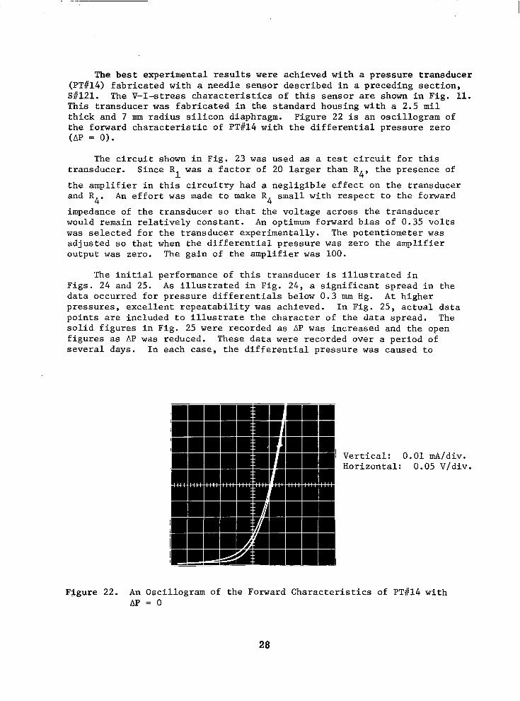
The b e s t e x p e r i m e n t a l r e s u l t s were achieved wi th a p res su re t r ansdu r :ce (PT1114) f a b r i c a t e d w i t h a n e e d l e s e n s o r d e s c r i b e d i n a pkeceding sec t ion , S#121. The V-I-stress c h a r a c t e r i s t i c s o f t h i s s e n s o r are shown i n F i g . 11. This t ransducer w a s f a b r i c a t e d i n t h e s t a n d a r d h o u s i n g w i t h a 2.5 m i l th ick and 7 m rad ius s i l i con d i aphragm. F igu re 22 is an osci l logram of t h e f o r w a r d c h a r a c t e r i s t i c o f PT1114 w i t h t h e d i f f e r e n t i a l p r e s s u r e z e r o (AP = 0 ) .
-
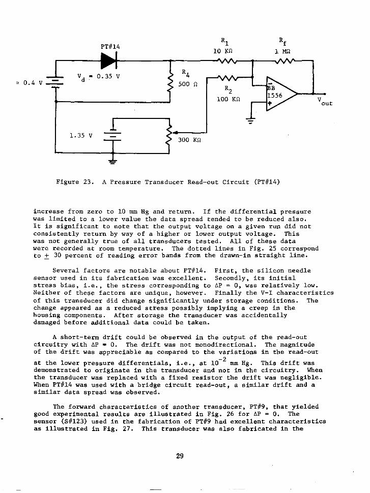
The c i r c u i t shown i n F i g . 23 was used as a tes t c i r c u i t f o r t h i s t ransducer . S ince R was a f a c t o r of 20 l a r g e r t h a n R4, t he p re sence of
t h e a m p l i f i e r i n t h i s c i r c u i t r y h a d a n e g l i g i b l e e f f e c t o n t h e t r a n s d u c e r and R An e f f o r t was made t o make R small wi th r e spec t t o t he fo rward
impedance of the t ransducer s o t h a t t h e v o l t a g e a c r o s s t h e t r a n s d u c e r would remain re la t ive ly cons tan t . An optimum forward b ias o f 0.35 v o l t s was s e l e c t e d f o r t h e t r a n s d u c e r e x p e r i m e n t a l l y . The poten t iometer was ad jus t ed s o t h a t when t h e d i f f e r e n t i a l p r e s s u r e was z e r o t h e a m p l i f i e r ou tput was zero. The ga in o f t he ampl i f i e r w a s 100.
1
4' 4
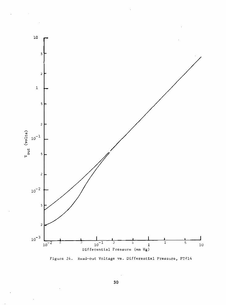
The i n i t i a l p e r f o r m a n c e of t h i s t r a n s d u c e r i s i l l u s t r a t e d i n F igs . 24 and 25. A s i l l u s t r a t e d i n F i g . 2 4 , a s i g n i f i c a n t s p r e a d i n t h e d a t a o c c u r r e d f o r p r e s s u r e d i f f e r e n t i a l s b e l o w 0 . 3 mm Hg. A t h ighe r p r e s s u r e s , e x c e l l e n t r e p e a t a b i l i t y was achteved . In F ig . 2 5 , a c t u a l d a t a p o i n t s are i n c l u d e d t o i l l u s t r a t e t h e c h a r a c t e r o f t h e d a t a s p r e a d . The s o l i d f i g u r e s i n F i g . 25 were recorded as AP was increased and t h e open f i g u r e s as AP was reduced. These data were recorded over a period of s e v e r a l d a y s . I n e a c h c a s e , t h e d i f f e r e n t i a l p r e s s u r e was caused t o
Vertical: 0.01 mA/div. Hor izonta l : 0.05 V/div.
F igure 22. An Osci l logram of the Forward Charac te r i s t ics of PTiI14 wi th AP = 0
28
PTW14 R1 Rf 10 KR 1MQ
= 0.4 v r
'd =
L
0.35 V R4 500 R
R2 100 KR Vout
1.35 v - 1- t 300 KR J
Figure 23. A Pressure Transducer Read-out Circuit (PT#14)
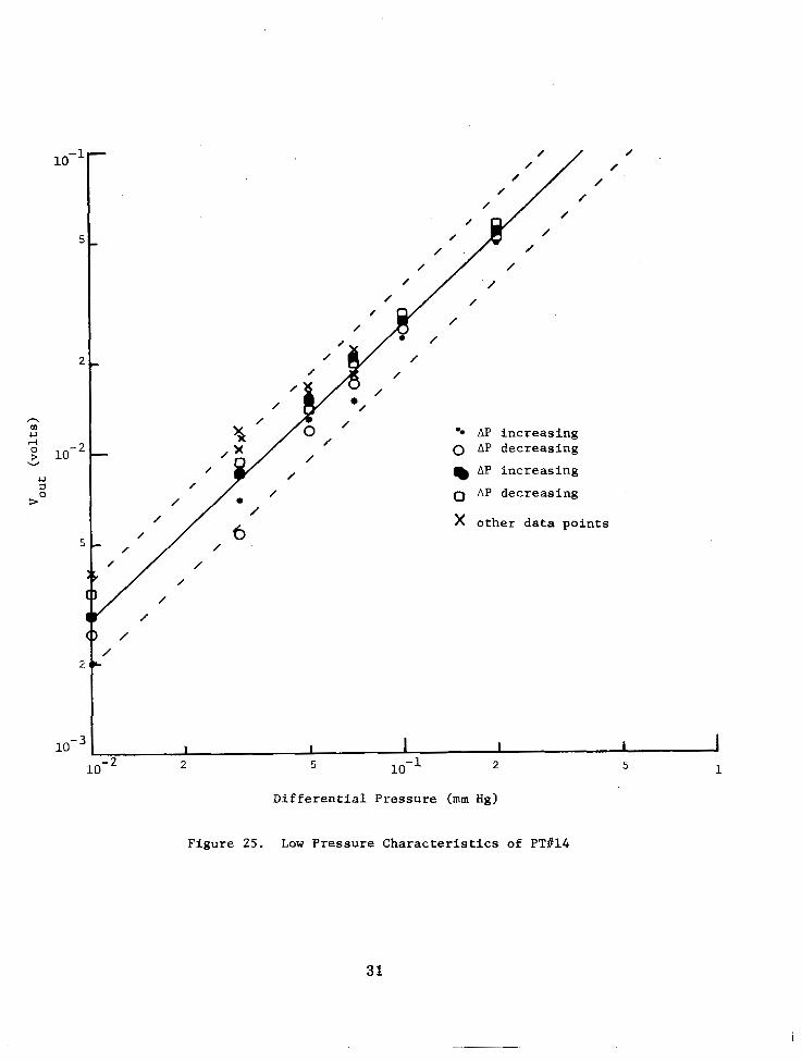
inc rease from zero to 10 mm Hg a n d r e t u r n . I f t h e d i f f e r e n t i a l p r e s s u r e was l i m i t e d t o a lower value the data spread tended to be reduced a lso. It is s i g n i f i c a n t t o n o t e t h a t t h e o u t p u t v o l t a g e on a g iven run d id no t c o n s i s t e n t l y r e t u r n by way of a h igher o r lower ou tput vo l tage . This was no t gene ra l ly t rue o f a l l t r a n s d u c e r s t e s t e d . A l l of t h e s e d a t a were recorded a t room temperature. The d o t t e d l i n e s i n F i g . 25 correspond t o 2 30 percent of reading error bands f rom the drawn-in s t ra ight l ine .
S e v e r a l f a c t o r s are notab le about PT#14. F i r s t , t h e s i l i c o n n e e d l e sensor used i n i ts f a b r i c a t i o n w a s excel lent . Secondly, i t s i n i t i a l stress b i a s , i . e . , t h e stress cor responding to AP = 0, was r e l a t i v e l y low. Nei ther of these factors are unique, however . Final ly the V-I c h a r a c t e r i s t i c s of t h i s t r ansduce r d id change s ign i f i can t ly unde r s to rage cond i t ions . The change appeared as a reduced stiress possibly implying a c r e e p i n t h e housing components. After storage the transducer was a c c i d e n t a l l y damaged be fo re add i t iona l da t a cou ld be t aken .
A shor t - t e rm d r i f t cou ld be obse rved i n t he ou tpu t o f t he r ead -ou t c i r c u i t r y w i t h AP = 0. The d r i f t was not monodirect ional . The magnitude of t h e d r i f t w a s app rec i ab le as compared t o t h e v a r i a t i o n s i n t h e r e a d - o u t
a t t h e l o w e r p r e s s u r e d i f f e r e n t i a l s , i. e., a t mm Hg. T h i s d r i f t w a s d e m o n s t r a t e d t o o r i g i n a t e i n t h e t r a n s d u c e r a n d n o t i n t h e c i r c u i t r y . When the t r ansduce r w a s rep laced wi th a f i x e d r e s i s t o r t h e d r i f t w a s n e g l i g i b l e . When PT#14 w a s used with a b r i d g e c i r c u i t r e a d - o u t , a similar d r i f t and a similar da ta spread was observed.
The fo rward cha rac t e r i s t i c s o f ano the r t r ansduce r , PT#9, t h a t y i e l d e d good e x p e r i m e n t a l r e s u l t s are i l l u s t r a t e d i n F i g . 26 f o r AP = 0. The sensor (S#123) used i n t h e f a b r i c a t i o n of PT#9 h a d e x c e l l e n t c h a r a c t e r i s t i c s as i l l u s t r a t e d i n F i g . 27. This t ransducer w a s a l s o f a b r i c a t e d i n t h e
29
10
5
2
1
5
2
n m 2 10-1 0 >
W
U 1 0 5
3
2
10- *
5
2
10-
.
Differential Pressure (mm Hg)
Figure 24. Read-out Voltage vs. Differential Pressure, PT!!14
30
/
/
/
/
AP increasing 0 AP decreasing
AP increasing
0 AP decreasing
x o t h e r data points
Differential Pressure (mm Hg)
Figure 25. Low Pressure Characteristics of PT#14
31
!
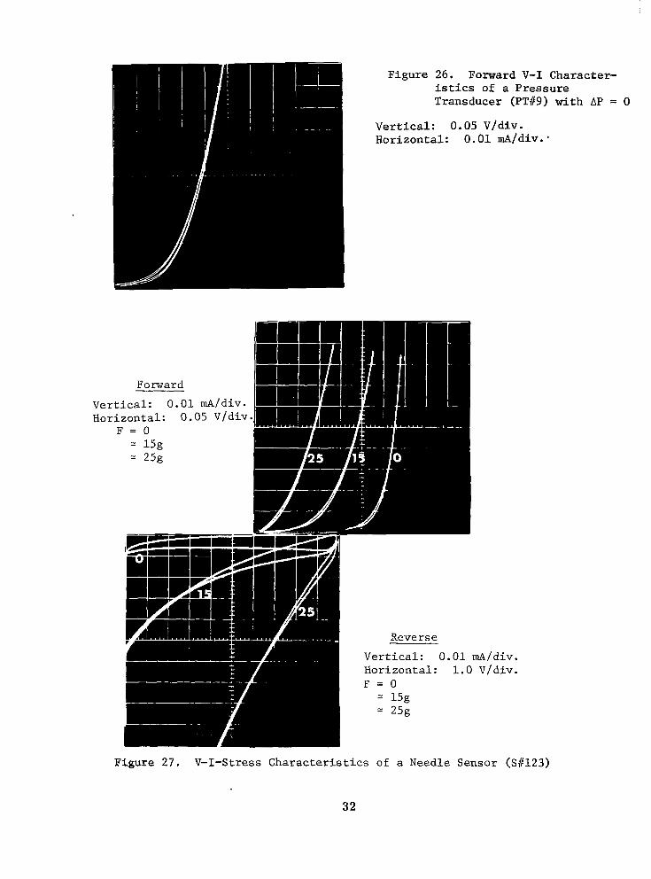
Figure 26. Forward V- I Character- istics of a P res su re Transducer (PTi19) wi th AP = 0
Vertical: 0.05 V/div. Hor izonta l : 0.01 rnA/div.'
Vert Hori
I
IAIdiv. V/div.
F igure 27. V-I-Stress C h a r a c t e r i s t i c s of a Needle Sensor (S i l 123 )
32
"
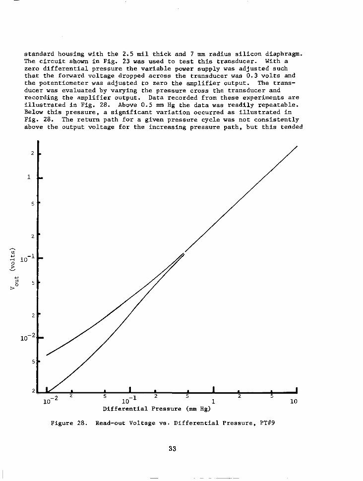
s tandard hous ing wi th the 2.5 m i l t h i c k and 7 mm rad ius s i l i con d iaphragm. The c i r c u i t shown i n F i g . 23 was u s e d t o test t h i s t r a n s d u c e r . With a z e r o d i f f e r e n t i a l p r e s s u r e t h e v a r i a b l e power supply was ad jus ted such that the forward vol tage dropped across the t ransducer was 0.3 v o l t s and the po ten t iome te r was ad jus t ed t o ze ro t he ampl i f i e r ou tpu t . The t rans- ducer w a s eva lua ted by va ry ing t he p re s su re c ros s t he t r ansduce r and r eco rd ing t he ampl i f i e r ou tpu t . Data recorded f rom these exper iments a re i l l u s t r a t e d i n F i g . 28. Above 0.5 mm Hg t h e d a t a was r ead i ly r epea tab le . Below t h i s p r e s s u r e , a s i g n i f i c a n t v a r i a t i o n o c c u r r e d as i l l u s t r a t e d i n Fig. 28. The r e t u r n p a t h f o r a g iven pressure cyc le was n o t c o n s i s t e n t l y above t he ou tpu t vo l t age fo r t he i nc reas ing p re s su re pa th , bu t t h i s t ended
D i f f e r e n t i a l P r e s s u r e (mm Hg)
Figure 28. Read-out Vo l t age v s . D i f f e ren t i a l P re s su re , PT#9
33

.I. I . . . .... . . . ... .- . .. .
t o b e t h e case. This experiment was repea ted a t room temperature over a per iod of several weeks with similar r e s u l t s . When the t r ansduce r was p l a c e d i n a low temperature environment, -50°C, and returned to room t empera tu re , t he t r ansduce r ' s cha rac t e r i s t i c s had changed and i t tended t o b e less s t a b l e .
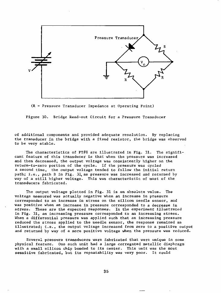
A more t y p i c a l t r a n s d u c e r t h a n e i t h e r PT#9 o r PT#14 is PTi18. The senso r (S#111) used i n t h e f a b r i c a t i o n o f t h i s t r a n s d u c e r was r e l a t i v e l y leaky. However, i t was s e n s i t i v e t o stress and the forward V-I charac te r - i s t i c w a s s t a b l e . The V-I-stress c h a r a c t e r i s t i c s o f Si1111 are i l l u s t r a t e d in t he o sc i l l og rams o f F ig . 29 . The f ab r i ca t ion t echn iques were s t anda rd and the s i l i con d iaphragm was 2.5 m i l s th ick and 7 mm i n d i a m e t e r . The read-out c i rcu i t ry used wi th PT#8 is i l l u s t r a t e d i n F i g . 30. A br idge of t h i s t y p e was f requent ly used as a r ead -ou t c i r cu i t ; i t r e q u i r e d a minimum
Forward
V e r t i c a l : 0 . 0 1 mA/div. Hor izonta l : 0.05 V/div.
F = O = 30g
Reverse
V e r t i c a l : 0.02 mAIdiv. Horizontal : 1 .0 Vldiv. F = O
30g
Figure 29. V-I-Stress C h a r a c t e r i s t i c s o f S f 1 1 1
34
- ~ "
H I
V
(R = Pressure Transducer Impedance a t O p e r a t i n g P o i n t )
Figure 30. Bridge Read-out Circui t for a Pressure Transducer
of additional components and provided adequate resolution. By r ep lac ing t h e t r a n s d u c e r i n t h e b r i d g e w i t h a f i x e d r e s i s t o r , t h e b r i d g e w a s observed t o b e v e r y s t a b l e .
The c h a r a c t e r i s t i c s of PT#8 are i l l u s t r a t e d i n F i g . 31. The s i g n i f i - c a n t f e a t u r e of t h i s t r a n s d u c e r is t h a t when t h e p r e s s u r e was increased and then decreased, the output vol tage was c o n s i s t e n t l y h i g h e r on t h e re turn- to-zero por t ion of the cyc le . If t h e p r e s s u r e w a s cycled a second t i m e , t h e o u t p u t v o l t a g e t e n d e d t o f o l l o w t h e i n i t i a l r e t u r n pa th ; i . e . , pa th B i n F i g . 34as p res su re was increased and re turned by way of a s t i l l h ighe r vo l t age . Th i s was c h a r a c t e r i s t i c of most of the t r ansduce r s f ab r i ca t ed .
The o u t p u t v o l t a g e p l o t t e d i n F i g . 31 is an abso lu t e va lue . The voltage measured w a s a c t u a l l y n e g a t i v e when a n i n c r e a s e i n p r e s s u r e cor responded to an increase in stress on t h e s i l i c o n n e e d l e s e n s o r , and w a s p o s i t i v e when an i nc rease i n p re s su re co r re sponded t o a d e c r e a s e i n stress. These are the expec ted r e sponses . In t he expe r imen t i l l u s t r a t ed i n F i g . 31 , an increas ing pressure cor responded to an increas ing stress. When a d i f f e r e n t i a l p r e s s u r e w a s app l i ed such t ha t an i nc reas ing p re s su re reduced the stress appl ied to the needle sensor , the response remained as i l l u s t r a t e d ; i . e . , the ou tput vo l tage increased f rom zero to a pos i t i ve ou tpu t and returned by way of a more p o s i t i v e v o l t a g e when t h e p r e s s u r e w a s reduced.
Several p re s su re t r ansduce r s were f a b r i c a t e d t h a t were unique i n some p h y s i c a l f e a t u r e . One such un i t had a large corregated metal l ic diaphragm wi th a small s i l i c o n c h i p bonded t o i t s cen te r . Th i s un i t was t h e most s e n s i t i v e f a b r i c a t e d , b u t its r e p e a t a b i l i t y w a s very poor. It could
35
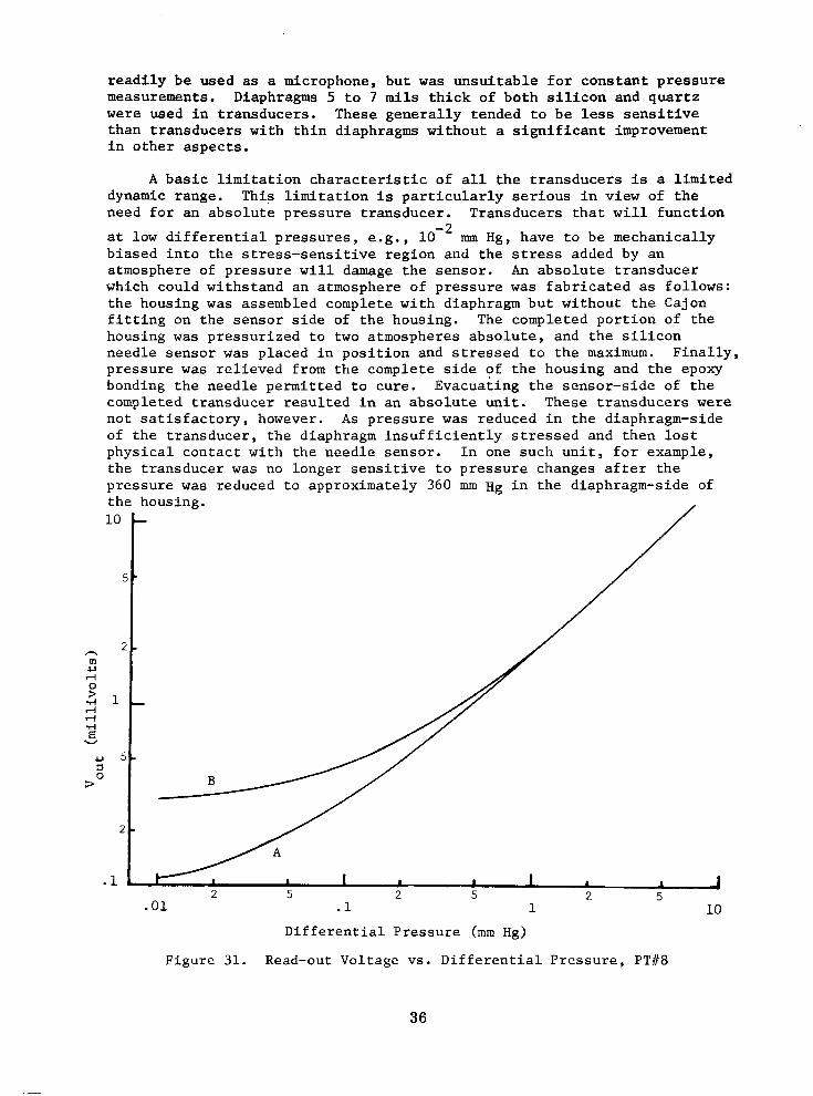
r e a d i l y b e u s e d as a microphone, but was u n s u i t a b l e f o r c o n s t a n t p r e s s u r e measurements. Diaphragms 5 t o 7 m i l s t h i c k of b o t h s i l i c o n and quar tz were used in t r ansduce r s . These gene ra l ly t ended t o be less s e n s i t i v e than t ransducers wi th th in d iaphragms wi thout a s i g n i f i c a n t improvement i n o t h e r a s p e c t s .
A b a s i c l i m i t a t i o n c h a r a c t e r i s t i c o f a l l t h e t r a n s d u c e r s i s a l i m i t e d dynamic range. This l imitat ion i s p a r t i c u l a r l y s e r i o u s i n v i e w o f t h e need fo r an abso lu t e p re s su re t r ansduce r . T ransduce r s t ha t w i l l f u n c t i o n
a t low d i f f e r e n t i a l p r e s s u r e s , e . g . , mm Hg, have to be mechanica l ly b i a s e d i n t o t h e s t r e s s - s e n s i t i v e r e g i o n a n d t h e stress added by an atmosphere of pressure w i l l damage t h e s e n s o r . An abso lu te t r ansduce r which could withstand an atmosphere of pressure w a s f a b r i c a t e d a s f o l l o w s : the housing was assembled complete with diaphragm but without the Cajon f i t t i n g on t he s enso r s ide of the hous ing . The completed port ion of the housing w a s p r e s s u r i z e d t o two a tmosphe res abso lu t e , and t he s i l i con needle sensor was p l a c e d i n p o s i t i o n a n d s t r e s s e d t o t h e maximum. F i n a l l y , p re s su re was relieved from the complete side of the housing and the epoxy bonding the needle permi t ted to cure . Evacuat ing the sensor -s ide of t h e comple t ed t r ansduce r r e su l t ed i n an abso lu t e un i t . These t r ansduce r s were n o t s a t i s f a c t o r y , however. A s pres su re was reduced in the d iaphragm-s ide of t h e t r a n s d u c e r , t h e d i a p h r a g m i n s u f f i c i e n t l y stressed and t hen l o s t phys ica l contac t wi th the needle sensor . In one such un i t , fo r example , t he t r ansduce r was no l o n g e r s e n s i t i v e t o p r e s s u r e c h a n g e s a f t e r t h e p re s su re was reduced to approximately 360 mm Hg in the d iaphragm-s ide of the housing.
D i f f e r e n t i a l P r e s s u r e (mm Hg)
Figure 31. Read-out Voltage vs. D i f f e r e n t i a l P r e s s u r e , PT#8
Discuss ion o f r e su l t s . - A l l o f t he da t a p re sen ted i n t he p reced ing s e c t i o n were recorded a t room temperature which was reasonably constant over the per iods o f time r e q u i r e d t o o b s e r v e d r i f t o r t o make an exper i - mental run. Furthermore, the observed dr i f t was no t a lways i n t he same di rec t ion . Consequent ly , t empera ture var ia t ions are concluded not to be t h e s o u r c e o f d r i f t a n d l a c k o f r e p e a t a b i l i t y o b s e r v e d i n t h e e x p e r i m e n t a l da t a . Se l f -hea t ing due t o an i n t e rna l power d i s s i p a t i o n c a n a l s o b e dismissed as a probable cause. Several experiments were run i n wh ich t he b r i d g e c i r c u i t and transducer were e l e c t r i c a l l y e x c i t e d o n l y when a d a t a po in t w a s t o b e r e a d a n d t h e r e s u l t s were similar to t hose ach ieved when e l e c t r i c a l e x c i t a t i o n was cons t an t ly app l i ed . Also, t h e d r i f t w a s no t a problem a t the h igh cu r ren t l eve l s co r re spond ing t o h igh stress.
The most p robable source o f the zero e r ror in t ransducers such as PT#8 i s c reep i n t he hous ing . When a d i f f e r e n t i a l p r e s s u r e is app l i ed s u c h t h a t t h e stress on the s enso r is increased, for example, the zero s h i f t i s i n a d i r e c t i o n t h a t c o r r e s p o n d s t o a n i n c r e a s e d stress. When the app l i ed p re s su re i s caused to decrease t h e stress a p p l i e d t o t h e senso r , t he ze ro sh i f t co r re sponds t o a decreased stress. The output vo l t age which e x i s t s a f t e r t h e d i f f e r e n t i a l p r e s s u r e h a s b e e n c y c l e d does no t d r i f t back t o ze ro . Gene ra l ly , t he d r i f t t ha t fo l lows such an experiment tends to be small r e l a t i v e l y t o t h e z e r o e r r o r t h a t h a s accumulated and i t is as l i k e l y t o i n c r e a s e as to re turn towards zero . It has been the experience of some manufac turers tha t a pre-s t ressed diaphragm w a s e s s e n t i a l t o z e r o s t a b i l i t y and low hys t e re s i s . Th i s s u g g e s t s t h a t a prestressed diaphragm may p r o v i d e f o r s i g n i f i c a n t improvements i n t r ansduce r s such a s PT#8.
Severa l t ransducers changed charac te r i s t ics dur ing tes t ing . In some i n s t a n c e s , t h e s e u n i t s were inadvertent ly exposed to excess pressure d i f f e r e n t i a l s . I n o t h e r cases, the reason for the change i s not obvious. The needle sensor from some of these t ransducers were recovered from the transducer housing and examined for damage. U s u a l l y , t h e s e n s o r t i p was found to be chipped.
The problem of damage and damage propagat ion a t t h e s e n s o r t i p c o u l d bene f i t f rom add i t iona l expe r imen ta l e f fo r t s . The u s u a l p r a c t i c e w i t h completed sensors w a s t o view t h e i r V-I c h a r a c t e r i s t i c s on a curve tracer and then apply an increasing stress t o e v a l u a t e t h e s e n s i t i v i t y of the sensors . This same procedure was a p p l i e d t o t h e s e n s o r s t h a t h a d good r e v e r s e c h a r a c t e r i s t i c s . It is p r o b a b l e t h a t a reverse leakage of 1 PA could not be observed on the curve tracer and, consequently, i t is p o s s i b l e t h a t t h e r e v e r s e l e a k a g e of a good sensor changed several o rde r s of magni- tude wi th increas ing stress be fo re i t w a s observed on the curve tracer.
37
It is u n f o r t u n a t e t h a t t h e b e t t e r s e n s o r s were not instrumented adequately t o o b s e r v e t h e reverse leakage a t zero stress.
Other needed inves t iga t ions were not completed due to a s h o r t a g e of needle sensors . Exper imenta l eva lua t ions o f d iaphragm s ize and material were inconc lus ive and i nves t iga t ions of bonding materials and environmental e f f e c t s were i n s u f f i c i e n t . An inc reased supp ly o f su i t ab le need le s enso r s w i l l make t h e s e i n v e s t i g a t i o n s p o s s i b l e .
The Simple Diaphragm
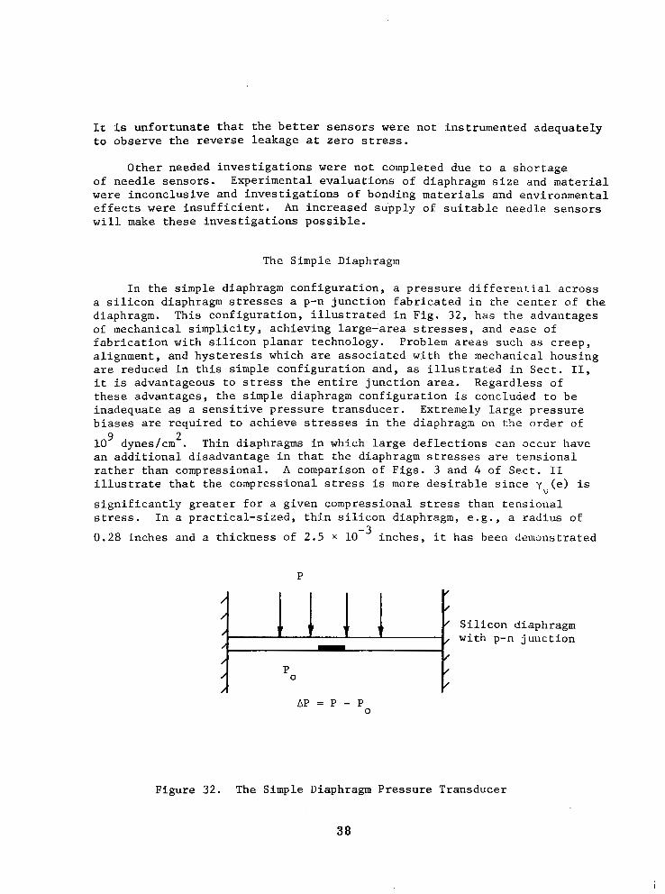
In the s imple diaphragm configurat ion, a p r e s s u r e d i f f e r e n t i a l a c r o s s a s i l i con d iaphragm stresses a p-n j u n c t i o n f a b r i c a t e d i n t h e c e n t e r o f t h e d iaphragm. This conf igura t ion , i l lus t ra ted in F ig . 32 , has t.he advantages of mechanical s implici ty , achieving large- 'area stresses, and ease of f ab r i ca t ion w i th s i l i con p l ana r t echno logy . P rob lem areas such as creep, alignment, and hysteresis which are assoc ia ted wi th the mechanica l hous ing are reduced in t h i s s imp le conf igu ra t ion and , as i l l u s t r a t e d i n Sec t . 11, i t is advantageous to stress t h e e n t i r e j u n c t i o n area. Regardless of these advantages, the s imple diaphragm configurat ion i s concluded to be inadequate as a sens i t i ve p re s su re t r ansduce r . Ex t r eme ly l a rge p re s su re b i a s e s are r equ i r ed t o ach ieve stresses i n t h e diaphragm on the order of
10 dynes/cm . Thin diaphragms i n which la rge def lec t ions can occur have an addi t iona l d i sadvantage in tha t the d iaphragm stresses are t e n s i o n a l ra ther than compressional . A comparison of Figs. 3 and 4 of Sect . I1 i l l u s t r a t e t h a t t h e c o m p r e s s i o n a l stress is more d e s i r a b l e s i n c e y (e) is
s i g n i f i c a n t l y g r e a t e r f o r a given compressional stress t h a n t e n s i o n a l stress. I n a p r a c t i c a l - s i z e d , t h i n s i l i c o n d i a p h r a g m , e . g . , a rad ius of
0.28 inches and a th ickness of 2.5 X 10 inches, i t has been demonstrated
9 2
v
-3
P
A P = P - P 0
Figure 32. The Simple Diaphragm Pressure Transducer
38
t h a t a p r e s s u r e d i f f e r e n t i a l o f more than 2 x lo3 mm Hg i s r e q u i r e d t o
achieve a diaphragm stress of 5 X lo9 dynes/cm2 (Ref. 1 ) . I n r e l a t i v e l y thick diaphragms i n which large compressional stresses can be achieved, e v e n g r e a t e r d i f f e r e n t i a l p r e s s u r e s are requi red . I f d iaphragm th ickness i s assumed t o b e a b o u t 1 / 4 of t h e r a d i u s , a p r e s s u r e d i f f e r e n t i a l o f
approximately 1.5 x lo3 mm Hg i s r e q u i r e d f o r a compressional stress of
10 dyneslcm . L a r g e r p r e s s u r e d i f f e r e n t i a l s r e s u l t i n a "ballooned" diaphragm and tensional stresses. I f t h e r a t i o of t h i c k n e s s t o r a d i u s i s reduced, the diaphragm w i l l "ba l loon" t o a t e n s i o n a l stress at a lower d i f f e ren t i a l p re s su re . These conc lus ions are based upon t h e r e s u l t s o f Roark (Ref. 8).
9 2
The Indenter-Point Configurat ion
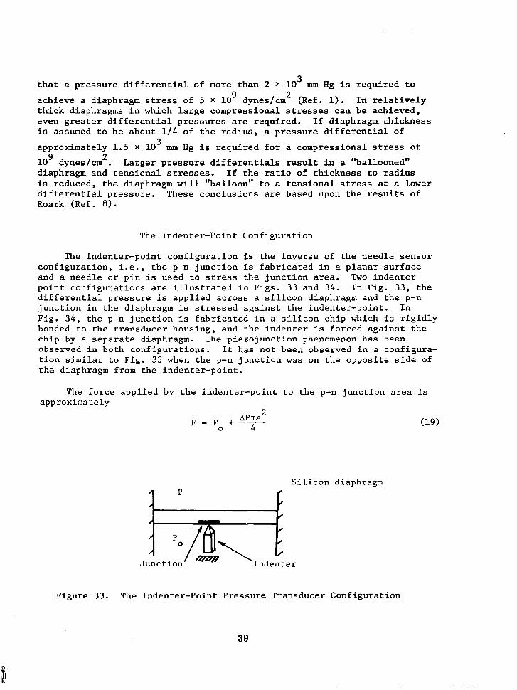
The indenter -poin t conf igura t ion is the i nve r se o f t he need le s enso r conf igu ra t ion , i . e . , t h e p-n j u n c t i o n is f a b r i c a t e d i n a p l a n a r s u r f a c e and a n e e d l e o r p i n i s u s e d t o stress t h e j u n c t i o n area. Two i nden te r po in t con f igu ra t ions are i l l u s t r a t e d i n F i g s . 33 and 3 4 . I n F i g . 3 3 , t h e d i f f e r e n t i a l p r e s s u r e is app l i ed ac ross a s i l icon diaphragm and the p-n junc t ion i n t he d i aphragm is stressed a g a i n s t t h e i n d e n t e r - p o i n t . I n F ig . 3 4 , t he p-n j u n c t i o n i s f a b r i c a t e d i n a s i l i c o n c h i p which i s r i g i d l y bonded to the t ransducer hous ing , and the indenter is fo rced aga ins t t he ch ip by a separate diaphragm. The p i ezo junc t ion phenomenon has been observed i n b o t h c o n f i g u r a t i o n s . It has no t been observed in a configura- t i o n similar t o F i g . 33 when t h e p-n j u n c t i o n was on t h e o p p o s i t e s i d e of the diaphragm from the indenter-point.
The fo rce app l i ed by the i nden te r -po in t t o t he p-n junc t ion area i s approximately
"
F = F +- A P T ~ ' 0 4
Junct ion Indent
S
:er
i l i c o n d i .aphragm
Figure 33. The Indenter-Point Pressure Transducer Configurat ion
39
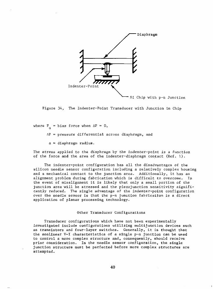
Inden ter-Point - Si Chip with p-n Junction Figure 3 4 , The Indenter-Point Transducer with Junction in Chip
where F = bias force when AP = 0 , 0
AP = pressure differential across diaphragm, and
a = diaphragm radius.
The stress applied to the diaphragm by the indenter-point is a function of the force and the area of the indenter-diaphragm contact (Ref. 1).
The indenter-point configuration has all the disadvantages of the silicon needle sensor configuration including a relatively complex housing and a mechanical contact to the junction area. Additionally, it has an alignment problem during fabrication which is difficult to overcome. In the event of misalignment it is likely that only a small portion of the junction area will be stressed and the piezojunction sensitivity signifi- cantly reduced. The single advantage of the indenter-point configuration over the needle sensor is that the p-n junction fabrication is a direct application of planar processing technology.
Other Transducer Configurations
Transducer configurations which have not been experimentally investigated include configurations utilizing multijunction devices such as transistors and four-layer switches. Generally, it is thought that the nonlinear V-I characteristics of a single p-n junction can be used to control a more complex structure and, consequently, should receive prior consideration. In the needle sensor configuration, the single junction structure must be perfected before more complex structures are attempted.
40
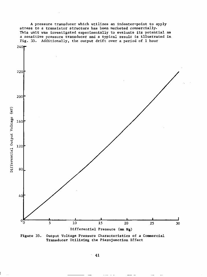
A pressure transducer which utilizes an indenter-point to apply stress to a transistor structure has been marketed commercially- This unit was investigated experimentally to evaluate its potential as a sensitive pressure transducer and a typical result is illustrated in Fig. 35. Additionally, the output drift over a period of 1 hour
5 10 15 20 25 30
Differential Pressure (nun Hg)
Figure 35. Output Voltage Pressure Characteristics of a Conrmercial Transducer Utilizing the Piezojunction Effect
41
correspond to approximate ly 7 mm Hg. The p u b l i s h e d s p e c i f i c a t i o n s r e f e r to' d i f f e r e n t i a l p r e s s u r e s g r e a t e r t h a n t h o s e o f i n t e r e s t h e r e a n d t h e t r ansduce r cou ld no t r e l i ab ly de t ec t t he low p r e s s u r e d i f f e r e n t i a l s
r equ i r ed , e .g . , lo-' mm Hg.
Read-out C i r c u i t r y
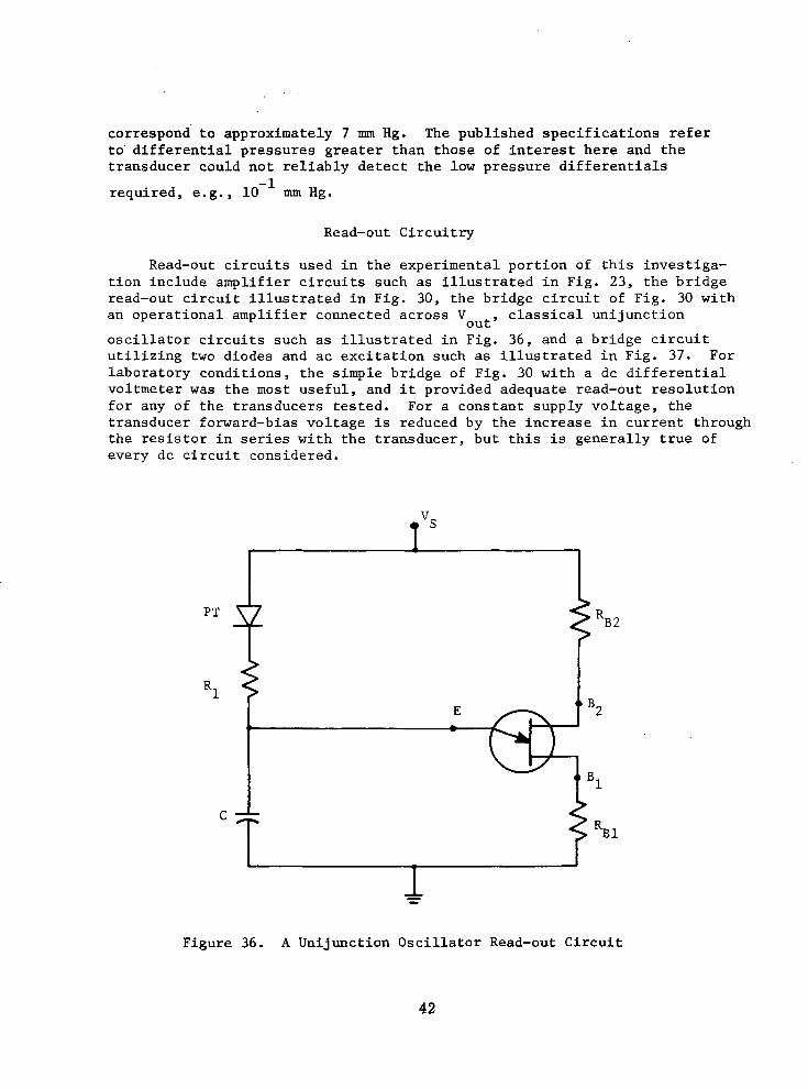
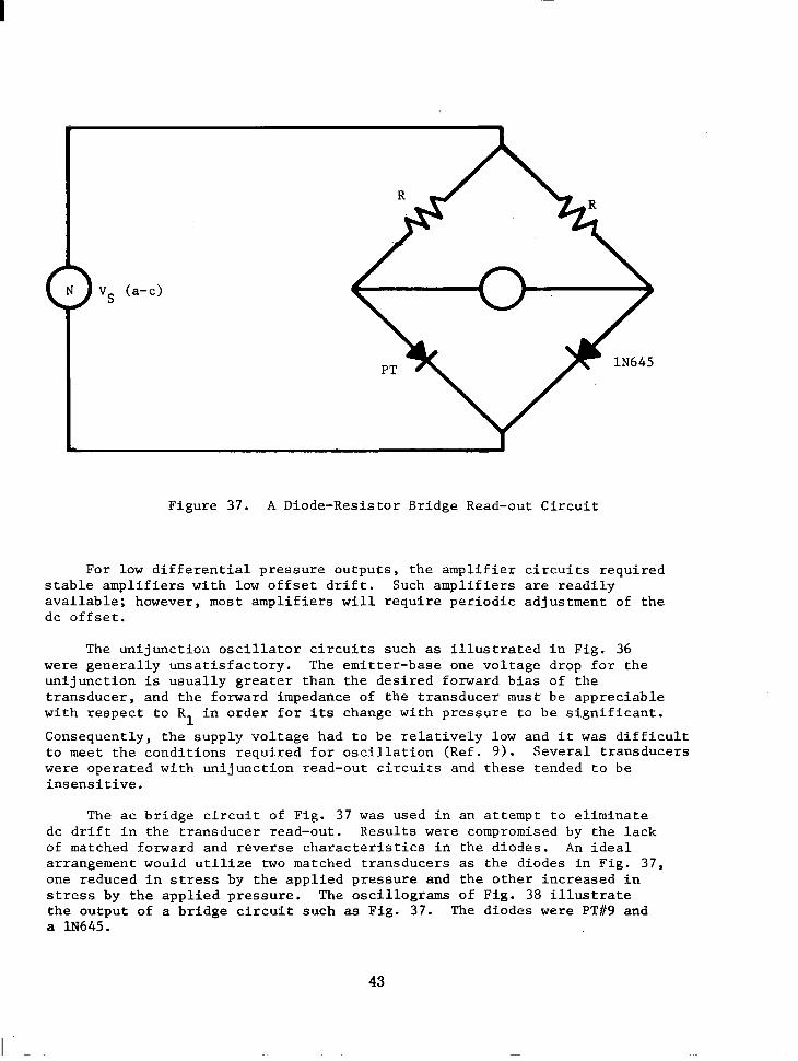
Read-out c i r c u i t s u s e d i n t h e e x p e r i m e n t a l p o r t i o n of t h i s i n v e s t i g a - t i o n i n c l u d e a m p l i f i e r c i r c u i t s s u c h a s i l l u s t r a t e d i n F i g . 23, t h e b r i d g e r e a d - o u t c i r c u i t i l l u s t r a t e d i n F i g . 30, t h e b r i d g e c i r c u i t of Fig. 30 wi th an opera t iona l ampl i f ie r connec ted across V c l a s s i c a l u n i j u n c t i o n
o s c i l l a t o r c i r c u i t s s u c h as i l l u s t r a t e d i n F i g . 36, and a b r i d g e c i r c u i t u t i l i z i n g two diodes and ac e x c i t a t i o n s u c h a s i l l u s t r a t e d i n F i g . 37. For l abora to ry cond i t ions , t he s imp le b r idge of F ig . 30 wi th a dc d i f f e r e n t i a l vo l tmeter was t h e most useful , and i t provided adequate read-out resolut ion f o r any of the t ransducers t es ted . For a cons tan t supply vo l tage , the t ransducer forward-bias vol tage i s reduced by the increase in cur ren t th rough t h e r e s i s t o r i n series w i t h t h e t r a n s d u c e r , b u t t h i s i s g e n e r a l l y t r u e of eve ry dc c i r cu i t cons ide red .
ou t ,
PT
R1
C
- Figure 36. A Uni junc t ion Osc i l l a to r Read-out C i r c u i t
r-
Figure 37 . A Diode-Resistor Bridge Read-out Circuit
For low d i f f e r e n t i a l p r e s s u r e o u t p u t s , t h e a m p l i f i e r c i r c u i t s r e q u i r e d s t a b l e a m p l i f i e r s w i t h low o f f s e t d r i f t . Such a m p l i f i e r s are r e a d i l y avai lable; however , most amplif iers w i l l r equi re per iodic ad jus tment o f the d c o f f s e t .
The u n i j u n c t i o n o s c i l l a t o r c i r c u i t s s u c h as i l l u s t r a t e d i n F i g . 36 w e r e g e n e r a l l y u n s a t i s f a c t o r y . The emi t te r -base one vo l tage d rop for the u n i j u n c t i o n i s usua l ly g rea te r than the des i red forward b ias o f the transducer, and the forward impedance of the transducer must be appreciable w i t h r e s p e c t t o R i n o r d e r f o r i ts change w i th p re s su re t o be s ign i f i can t .
C o n s e q u e n t l y , t h e s u p p l y v o l t a g e h a d t o b e r e l a t i v e l y low and i t w a s d i f f i c u l t t o meet t h e c o n d i t i o n s r e q u i r e d f o r o s c i l l a t i o n ( R e f . 9 ) . Several t ransducers were opera ted wi th un i junc t ion read-out c i rcu i t s and these t ended to be i n s e n s i t i v e .
1
The ac b r i d g e c i r c u i t o f F i g . 37 was used i n a n a t t e m p t t o e l i m i n a t e d c d r i f t i n t h e t r a n s d u c e r r e a d - o u t . R e s u l t s were compromised by t h e l a c k of matched forward and reverse c h a r a c t e r i s t i c s i n t h e d i o d e s . An i d e a l a r rangement would u t i l i ze two matched transducers as the d iodes i n F ig . 37 , one reduced i n stress by the app l i ed p re s su re and t h e o t h e r i n c r e a s e d i n stress by t h e a p p l i e d p r e s s u r e . The osci l lograms of Fig. 38 i l l u s t r a t e the ou tput o f a b r i d g e c i r c u i t s u c h as Fig. 37 . The diodes were PT#9 and a 1N645.
43
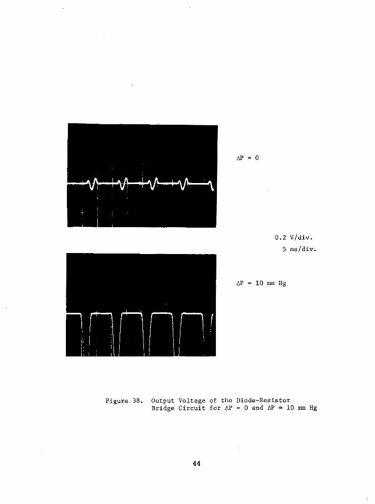
0.2 Vldiv.
5 msldiv.
Figure 38. Output Voltage of the Diode-Resistor B r i d g e C i r c u i t f o r AP = 0 and AP = 10 mm Hg
44
SECTION I V
CONCLUSIONS AND RECOMMENDATIONS
D u r i n g t h e c o u r s e o f t h i s i n v e s t i g a t i o n , s i g n i f i c a n t p r o g r e s s w a s made toward the development of p i e z o j u n c t i o n t r a n s d u c e r s . S e n s i t i v e s i l i c o n need le s enso r s were f a b r i c a t e d w i t h e x c e l l e n t p-n j u n c t i o n c h a r a c t e r i s t i c s , and these were used in p re s su re t r ansduce r s w i th encourag ing r e su l t s . These r e s u l t s d e m o n s t r a t e t h e f e a s i b i l i t y of u t i l i z i n g t h e s e n s i t i v e , p i e z o - j u n c t i o n phenomenon i n a small, so l id - s t a t e p re s su re t r ansduce r . Th i s i s an excellent beginning; however, much development remains t o b e done.
Because of t h e many advantages o f the needle sensor conf igura t ion , much o f t h e e f f o r t of t h i s s t u d y w a s directed toward the development of a process fo r f ab r i ca t ing t hese s enso r s . A l though t he y i e ld of sensors remained low and a c t u a l l y compromised t h e t o t a l r e s u l t s of t h i s i n v e s t i g a t i o n , i t i s very probable tha t a h i g h - y i e l d f a c i l i t y w i l l evolve. I n view of developments t ha t have occu r red i n o the r areas of semiconductor processing, there i s every reason to expect the eventual development of an automated, high-yield f a c i l i t y p r o d u c i n g c o n s i s t e n t l y g o o d - q u a l i t y n e e d l e s e n s o r s . I t i s a l s o reasonable to expec t the sensor qua l i ty to improve s o as t o y i e l d more s e n s i t i v e devices.
The t r a n s d u c e r s f a b r i c a t e d d u r i n g t h i s i n v e s t i g a t i o n were l i m i t e d i n number by t h e low y i e l d of needle sensors . Transducers were f a b r i c a t e d ,
however , which resolved different ia l pressures of 10 mm Hg. The usefu lness of these t ransducers were l i m i t e d by z e r o e r r o r , d r i f t and a lack of r epea tab i l i t y a t t he l ower p re s su res . These l imi t a t ions a r e l i ke ly t o be c h a r a c t e r i s t i c o f t he hous ing conf igu ra t ion r a the r t han t he need le s enso r o r t h e p i e z o j u n c t i o n phenomenon. An adequate supply o f need le s enso r s w i l l provide opportuni ty for the development of an improved housing and an expe r imen ta l p rog ram to eva lua te t he cha rac t e r i s t i c s o f t h e s e n s o r s independent ly of a housing.
-2
The bes t t r ansduce r s f ab r i ca t ed were no t a typ ica l , bu t t hey were similar t o e a c h o t h e r i n t h a t t h e y u t i l i z e d good q u a l i t y n e e d l e s e n s o r s and t he ze ro p re s su re s t r e s s -b i a s w a s r e l a t i v e l y small. Typical ly , they used a th in s i l i con d iaphragm which w a s n o t s t r e s s e d when bonded t o t h e t ransducer housing. It is r e a s o n a b l e t o e x p e c t t h a t s i g n i f i c a n t improve- ments could be achieved through improved diaphragm design, and it is reasonab le t ha t good q u a l i t y s e n s o r s a n d s m a l l i n i t i a l stresses y ie lded t h e b e s t e x p e r i m e n t a l r e s u l t s . A t r ansduce r des ign fo r t he need le s enso r is i n i t s infancy and w i l l mature with an adequate supply of sensors .
While t h e r e is e v e r y r e a s o n t o e x p e c t s i g n i f i c a n t improvement i n these t r ansduce r s , t he re are f a c t o r s t h a t may l i m i t t h e i r u l t i m a t e usefu lness . The s e n s i t i v e t r a n s d u c e r s f a b r i c a t e d d u r i n g t h i s i n v e s t i g a t i o n
45
were l i m i t e d i n t h e maximum d i f f e r e n t i a l p r e s s u r e t h e y c o u l d w i t h s t a n d . The high stress r e q u i r e d f o r t h e p i e z o j u n c t i o n phenomenon t o o c c u r is c l o s e t o t h e f r a c t u r e stress of s i l i c o n , a n d t h e s e n s o r s a r e e a s i l y damaged by s m a l l i n c r e a s e s i n stress. T h i s f a c t o r d o e s n o t limit s e n s i t i v i t y , however , and the sensi t ivi ty can be t raded-off for dynamic range. These t ransducers are a l s o s e n s i t i v e t o t e m p e r a t u r e s i n c e t h i s is i n h e r e n t i n t h e p-n junct ion, and temperature compensat ion w i l l be r equ i r ed i n most a p p l i c a t i o n s . The ou tpu t o f t he p i ezo junc t ion t r ansduce r s a l so tends to be smal l , i . e . , on t h e o r d e r of the forward vo l tage across the p-n junc t ion ; however , th i s is c h a r a c t e r i s t i c o f m o s t s e n s i t i v e t r a n s d u c e r s .
The e x p e r i m e n t a l r e s u l t s a c h i e v e d i n t h i s i n v e s t i g a t i o n r e p r e s e n t a good beg inn ing . Sens i t i ve p re s su re t r ansduce r s u t i l i z ing t he p i ezo junc t ion phenomenon were f a b r i c a t e d . T h e s e r e s u l t s are not conclusive, however. The low y i e l d of need le s enso r s l imi t ed t he expe r imen ta l eva lua t ion of var ious a t t r ibu tes o f the comple te t ransducer assembly and addi t iona l e f f o r t s i n t h i s p h a s e of the development are needed. It is concluded tha t an adequate supply o f needle sensors would qu ick ly y ie ld s ign i f icant improvements i n t h e p i e z o j u n c t i o n p r e s s u r e t r a n s d u c e r s , a n d t h a t a n e f f o r t t o ob ta in such a supply is warranted.
46
APPENDIX A
THE REIATIONSHIP OF STRESS TO STRAIN
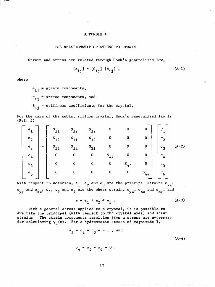
S t r a i n and stress are re la ted th rough Hook's gene ra l i zed l a w ,
where
eij = s t r a i n components,
u = stress components, and
S = s t i f f n e s s c o e f f i c i e n t s for t h e c r y s t a l . i j
i j
For the case o f t h e c u b i c , s i l i c o n c r y s t a l , Hook's generalized law is (Ref. 5)
el
e2
e 3
e4
e5
e6
- - 11 12 3 2
12 sll
s12 s12 sll 0 0
s44 0
0 0 0
0 0 0
0
0
0
0 0 0
0 0 0 0
0 0 0 0 0
s44
s44
"
'1
u2
U 3
u4
u5
'6 "
. (A-2)
With r e s p e c t t o n o t a t i o n , el, e2 and e a r e t h e p r i n c i p a l s t r a i n s e 3 xx ' e and e - e4? e5 and e6 are t h e s h e a r s t r a i n s e e and e - and
YY zz' yz' xz Xy'
e = e l + e 2 + e 3 . (A- 3
With a gene ra l stress a p p l i e d t o a c r y s t a l , i t is p o s s i b l e t o e v a l u a t e t h e p r i n c i p a l ( w i t h r e s p e c t t o t h e c r y s t a l a x e s ) a n d s h e a r s t r a i n s . The s t r a i n components r e s u l t i n g from a stress a re necessa ry f o r c a l c u l a t i n g y (e) . For a h y d r o s t a t i c stress of magnitude T,
V
u1 = u2 = O 3 - - - T , and
(A-4)
47
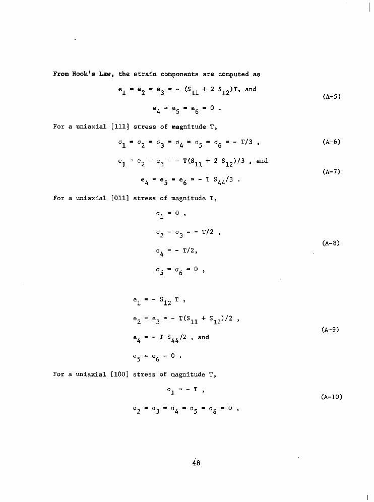
From Hook's Law, the strain components are computed as
el = e2 = e3 = - (Sll + 2 S )T, and
e 4 - e 5 = e 6 = 0 . - 12
For a uniaxial [111] stress of magnitude T,
u1 = a2 = u3 - - u4 = u5 - - u6 = - T/3 ,
el = e2 = e3 = - T(Sll + 2 S12)/3 , and
e4 = e5 = e6 = - T S 4 4 / 3 . For a uniaxial [Oll] stress of magnitude T,
u = o , 1
a2 = a3 = - T/2 ,
a4 = - T/2,
u 5 - u 6 = 0 - ,
e = - S12T , 1
e2 = e3 = - T(Sll + SI2)/2 ,
e4 = - T S44/2 , and
e 5 = e 6 = 0 .
For a uniaxial [10O] stress of magnitude T,
u = - 1 T Y
u 2 = u 3 = u 4 - u 5 = u 6 = 0 - ,
(A-5)
(A-10)
48
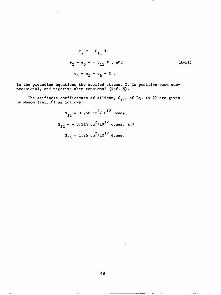
e = - S l l T , 1
e2 = e3 = - S12 T , and
e4= e5 = e6 = 0 . In the preceding equations the applied stress, T, is positive when com- pressional, and negative when tensional (Ref. 5).
The stiffness coefficients of silicon, S of Eq. (A-2) are given by Mason (Ref. lo) as follows: ij '
sll = 0.768 cm2/1012 dynes,
s12 = - 0.214 cm2/1012 dynes, and
(A-11)
s44 = 1.26 cm2/1012 dynes.
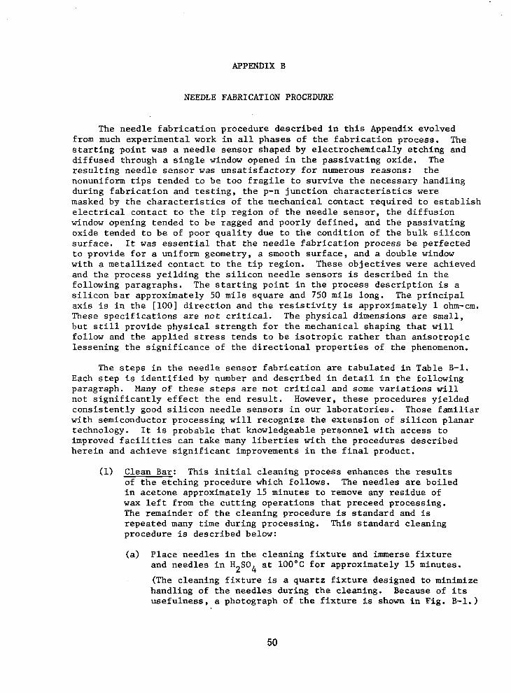
APPENDIX B
NEEDLE FABRICATION PROCEDURE
The n e e d l e f a b r i c a t i o n p r o c e d u r e d e s c r i b e d i n t h i s Appendix evolved from much experimental work i n a l l phases o f t he f ab r i ca t ion p rocess . The s t a r t i n g p o i n t w a s a needle sensor shaped by e lec t rochemica l ly e tch ing and diffused through a s i n g l e window opened i n the pas s iva t ing ox ide . The r e s u l t i n g n e e d l e s e n s o r was u n s a t i s f a c t o r y f o r numerous reasons : the nonuniform t i p s t e n d e d t o b e t o o f r a g i l e t o s u r v i v e t h e n e c e s s a r y h a n d l i n g d u r i n g f a b r i c a t i o n and t e s t i n g , t h e p-n j u n c t i o n c h a r a c t e r i s t i c s were masked by the cha rac t e r i s t i c s o f t he mechan ica l con tac t r equ i r ed t o e s t ab l i sh e l e c t r i c a l c o n t a c t t o t h e t i p r e g i o n of t h e n e e d l e s e n s o r , t h e d i f f u s i o n window opening tended to b e ragged and poorly def ined, and the passivat ing ox ide t ended t o be o f poor qua l i t y due t o t he cond i t ion o f t he bu lk s i l i con su r face . It was e s s e n t i a l t h a t t h e n e e d l e f a b r i c a t i o n p r o c e s s b e p e r f e c t e d t o p r o v i d e f o r a uniform geometry, a smooth sur face , and a double window wi th a me ta l l i zed con tac t t o t he t i p r eg ion . These ob jec t ives were achieved and t h e p r o c e s s y e i l d i n g t h e s i l i c o n n e e d l e s e n s o r s is d e s c r i b e d i n t h e fol lowing paragraphs. The s t a r t i n g p o i n t i n t h e p r o c e s s d e s c r i p t i o n is a s i l i con ba r app rox ima te ly 50 mils square and 750 m i l s long. The p r i n c i p a l a x i s i s i n t h e [ l o o ] d i r e c t i o n and t h e r e s i s t i v i t y is approximately 1 ohm-cm. T h e s e s p e c i f i c a t i o n s a r e n o t c r i t i c a l . The physical dimensions are small, bu t s t i l l p rov ide phys i ca l s t r eng th fo r t he mechan ica l shap ing t ha t w i l l fol low and the app l i ed stress t e n d s t o b e i s o t r o p i c r a t h e r t h a n a n i s o t r o p i c l e s sen ing t he s ign i f i cance o f t he d i r ec t iona l p rope r t i e s of t h e phenomenon.
The s t e p s i n t h e n e e d l e s e n s o r f a b r i c a t i o n are t a b u l a t e d i n T a b l e B-1. Each s t e p is i d e n t i f i e d by number a n d d e s c r i b e d i n d e t a i l i n t h e f o l l o w i n g paragraph. Many of these s teps are not c r i t i ca l and some v a r i a t i o n s w i l l n o t s i g n i f i c a n t l y e f f e c t t h e end r e s u l t . However, these p rocedures y ie lded c o n s i s t e n t l y good s i l i con need le s enso r s i n ou r l abo ra to r i e s . Those f ami l i a r with semiconductor processing w i l l r ecognize the ex tens ion of s i l i c o n p l a n a r technology. It is probable that knowledgeable personnel with access to improved f a c i l i t i e s c a n t a k e many l iber t ies wi th the p rocedures descr ibed h e r e i n and ach ieve s ign i f icant improvements in the f ina l p roduct .
(1) Clean Bar: T h i s i n i t i a l c l e a n i n g p r o c e s s e n h a n c e s t h e r e s u l t s of the e tch ing procedure which fo l lows . The needles are bo i l ed in ace tone approx ima te ly 15 minu te s t o remove any r e s idue of wax l e f t from the cu t t i ng ope ra t ions t ha t p receed p rocess ing . The remainder of the c leaning procedure is s tandard and is repea ted many t i m e during processing. This s tandard c leaning procedure is described below:
( a ) P l ace need le s i n t he c l ean ing f i x tu re and immerse f i x t u r e and need le s i n H SO a t 100°C for approximately 15 minutes.
(The c l e a n i n g f i x t u r e is a qua r t z f i x tu re des igned t o min imize handl ing of the needles during the c leaning. Because of i t s use fu lness , a photograph of the f ix ture is shown i n F i g . B-1.)
2 4
50
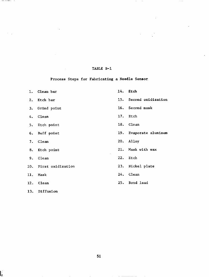
TABLE B-1
1.
2.
3.
4.
5.
6 .
7.
8 .
9 .
10.
11.
12.
13.
Process S teps for Fabricating a Needle Seneor
Clean bar
Etch bar
Grind point
Clean
Etch point
Buff point
Clean
Etch point
Clean
First oxidization
Mask
Clean
Diffusion
14.
15.
16.
17.
18.
19.
20.
21.
22.
23.
24.
25.
Etch
Second oxidization
Second mask
Etch
Clean
Evaporate aluminum
Alloy
Mask with wax
Etch
Nickel plate
Clean
Bond lead
51
Rinse f i x tu re and need le s i n f l owing D I H20 f o r one minute.
Immerse f i x t u r e a n d n e e d l e s i n g e n t l y b o i l i n g D I H 0 f o r
5 minu tes , and r i n se i n f l owing D I H20 f o r 5 minutes.
Immerse f i x t u r e and needles i n HNO a t 8OoC fo r 15 minu te s .
Repeat Step (b).
2
3
Immerse n e e d l e s i n g e n t l y b o i l i n g D I H 0 f o r 5 minutes, and r i n s e i n f l o w i n g D I H 0 f o r 20 minutes. 2
Immerse t h e n e e d l e s i n warm Transene fo r 5 minutes .
2
Using clean tweezers, remove the needles from the need le c l e a n i n g f i x t u r e and blow each needle dry with N Keep
n e e d l e s i n T r a n s e n e u n t i l t h e y are removed f o r blowing dry. Load the d ry needles immedia te ly in to a c l e a n p e t r i d i s h w i t h c l e a n f i l t e r p a p e r and t r a n s f e r as qu ick ly a s poss ib l e in to t he appropr i a t e fu rnace boa t . (No te : The maximum hold time is only the time n e c e s s a r y t o blow the need le s d ry , p l ace them on a fu rnace boa t and p l ace t he boa t i n t h e p r o f i l e f l a t zone of t he fu rnace t ube . Only v i s u a l i n spec t ion i s pe rmi t t ed du r ing t he d ry n i t rogen blow o f f per iod . Any e x t r a h o l d i n g o r h a n d l i n g a t t h i s s t a g e r e q u i r e s a r e p e a t o f t h e e n t i r e c l e a n i n g p r o c e s s ) .
2'
Etch Bar: The needle bars are immersed f o r 20 s e c o n d s i n a n a g i t a t e d e t c h s o l u t i o n c o n s i s t i n g o f 3 p a r t s HNO and 1 p a r t HF. 3
Grind Point: The i n i t i a l p o i n t s h a p i n g is done by b r i n g i n g t h e sp inn ing need le i n to con tac t w i th a s t a t i o n a r y c o p p e r p l a t e a t an angle of 60" . The needle is tu rn ing a t approximately 10,000 rpm. The coppe r p l a t e is coa ted wi th a 15 micron alumina g r i t . G r i n d i n g i s terminated when the need le p ro f i l e app rox ima tes t h e s h a p e i l l u s t r a t e d i n F i g . B - 2 . This r equ i r e s a judgment dec i s ion by a n e x p e r i e n c e d , s k i l l e d o p e r a t o r .
C l e a n : B o i l t h e n e e d l e s i n a c e t o n e f o r 1 5 m i n u t e s a n d i n TCE fo r 15 minu te s . The remainder of this c leaning procedure i s t h e s tandard p rocedure descr ibed in No. 1.
Etch Point : The need le s a r e e t ched i n t he so lu t ion o f 3 p a r t s HNO and 1 p a r t HF f o r 10 t o 20 seconds as required to round the po in t and smooth t h e s u r f a c e . The e t c h s o l u t i o n is caused to flow smoothly around a beaker and the needle i s immersed i n t o t h e e t c h a n t w i t h t h e p o i n t h e a d e d d i r e c t l y i n t o t h e e t c h a n t flow. The n e e d l e s a r e h e l d i n t h e e t c h a n t by tweezers a t t h e very back of the shank.
3
52
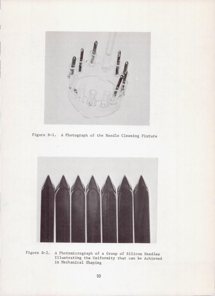
,....--0---
Figure B-1. A Photograph of the Needle Cleaning Fixture
Figure B-2. A Photomicrograph of a Group of Silicon Needles Illustrating the Uniformity that can be Achieved in Mechanical Shaping
53
( 6 ) Buff Point: The need le po in t ' is b u f f e d a g a i n s t a 1 1/2" f e l t wheel turning a t 1800 rpm and is charged wi th a 6 micron diamond g r i t p a s t e . The needle is a l so caused t o spin a t approximately 1800 rpm. Buffing is c o n t i n u e d u n t i l t h e n e e d l e p o i n t h a s acqu i r ed t he des i r ed shape . I n Step ( 5 ) and ( 6 ) , a judgement dec i s ion by an expe r i enced , sk i l l ed ope ra to r i s requ i r ed .
(7) Clean: This cleaning procedure is i d e n t i c a l t o t h e c l e a n i n g p rocedure desc r ibed i n No. ( 4 ) .
(8) A Fina l E tch : This e tch p rocedure is i d e n t i c a l t o t h e p r o c e d u r e d e s c r i b e d i n No. (5).
(9) Clean: This procedure is i d e n t i c a l t o the s tandard p rocedure o f No. (1). A t the conclus ion of th i s c leaning s tep , the mechanica l shaping of the needles is completed. As no ted , several of these s t eps r equ i r e i nd iv idua l hand l ing o f t he need le s by an ope ra to r , and a l s o a q u a l i t y judgement by the operator. The extent to which uniformity of shape was achieved is remarkable. This uniformity is i l l u s t r a t e d i n F i g . B-2 which is a photomicrograph of a group of 7 needles which were mechanically shaped from a l o t of 8.
(10) F i r s t Ox id iza t ion : Place t h e c l e a n e d n e e d l e s i n a n o x i d a t i o n 0
f u r n a c e a t 1100°C and grow a 10,000 A oxide. A dry-wet-dry oxidat ion procedure is used as fol lows: 10 minutes i n O2 at
1000 cc per minute; 115 minutes in steam and 20 m i n u t e s i n O2 a t 1000 cc per minute.
(11) Mask: The masking procedure is as fol lows:
(a) Preheat the needles in an oven and dip the s t i l l warm needles i n t o a container of JKPR t o a po in t abou t ha l f way up t h e shank three times.
(b) Heat t h e n e e d l e s i n a n oven a t 85OC fo r 15 minu te s .
(c ) Melt apiezon black wax on a g l a s s s l i d e a n d p u l l a second s l i d e o v e r t h e wax so as t o o b t a i n a v e r y t h i n l a y e r .
(d) Using a s p e c i a l s p r i n g h o l d e r , h o l d t h e t i p s o f t h e n e e d l e s aga ins t the wax-coa ted s l ide for one minute .
( e ) L i f t t h e n e e d l e s f r e e of t h e w a x and a l low to a i r d r y f o r 2 minutes.
( f ) As b e f o r e , d i p t h e n e e d l e s i n t o t h e c o n t a i n e r o f KPR t h r e e times and a i r d ry fo r t en minu te s .
(8) Repeat Steps (dl and (e).
54
(h) Expose each needle under UV l i g h t f o r f o u r m i n u t e s .
( i ) Develop i n TCE f o r 2.5 minutes.
( j ) B a k e a t 16OoC f o r 15 minutes.
(k) Etch i n b u f f e r e d HF f o r 7 minutes.
(1) Remove KPR by immersing i n H2S04.
Except for the b lack wax masking these procedures were r e a d i l y adapted from si l icon planar technology. This unique masking technique is i l l u s t r a t e d i n t h e p h o t o g r a p h of Fig. B-3 which shows a s i n g l e n e e d l e mounted i n t h e s p e c i a l s p r i n g f i x t u r e and he ld aga ins t the wax-coa ted s l ide .
Clean: Use the s tand procedure of No. (1) .
Diffusion: The d i f fus ion parameters are t y p i c a l l y as fol lows: 20 minutes a t llOO°C, 40 ppm of B2H6 and 50 cc per minute of 0
A f t e r t h e d i f f u s i o n t h e O2 flow i s cont inued for approximate ly
5 minutes.
2'
Etch: The n e e d l e s a r e e t c h e d i n a s o l u t i o n of 10 p a r t s D I H20
and one p a r t HF f o r 20 seconds.
Second Oxidation: The second oxide is grown a t 1100°C using a dry-wet-dry procedure as fol lows: 10 minu tes i n 02, 30 minutes i n steam, and 20 m i n u t e s i n 02.
Second Mask: The second masking procedure provides for a contac t window t o t h e d i f f u s e d t i p of the needle . The procedure is i d e n t i c a l t o t h e f i r s t masking s t e p d e s c r i b e d i n No. (11) excep t i n one impor t an t de t a i l . It is r e q u i r e d t h a t t h e c o n t a c t window be made smaller than t he f irst o r d i f f u s i o n window, and l i e w h o l l y i n s i d e t h e d i f f u s i o n window. This i s accomplished by using a t h i n n e r l a y e r of wax on t h e wax-coated s l ide . Success i s dependent upon the judgement and s k i l l of t h e o p e r a t o r . I f s u c c e s s f u l , t h e two openings can be readi ly ident i f ied under a micros cope.
Etch: The contact window is opened by a 7 minu te e t ch i n bu f fe red HI?. Clean: This procedure is i d e n t i c a l t o t h e s t a n d a r d p r o c e d u r e of No. (1).
Evaporate Aluminum: In t he evapora t ion fu rnace t he need le s are masked i n a s p e c i a l f i x t u r e so as t o restrict t h e aluminum t o a narrow s t r i p from t h e t i p t o a po in t s t i l l below the beginning
55
I. .
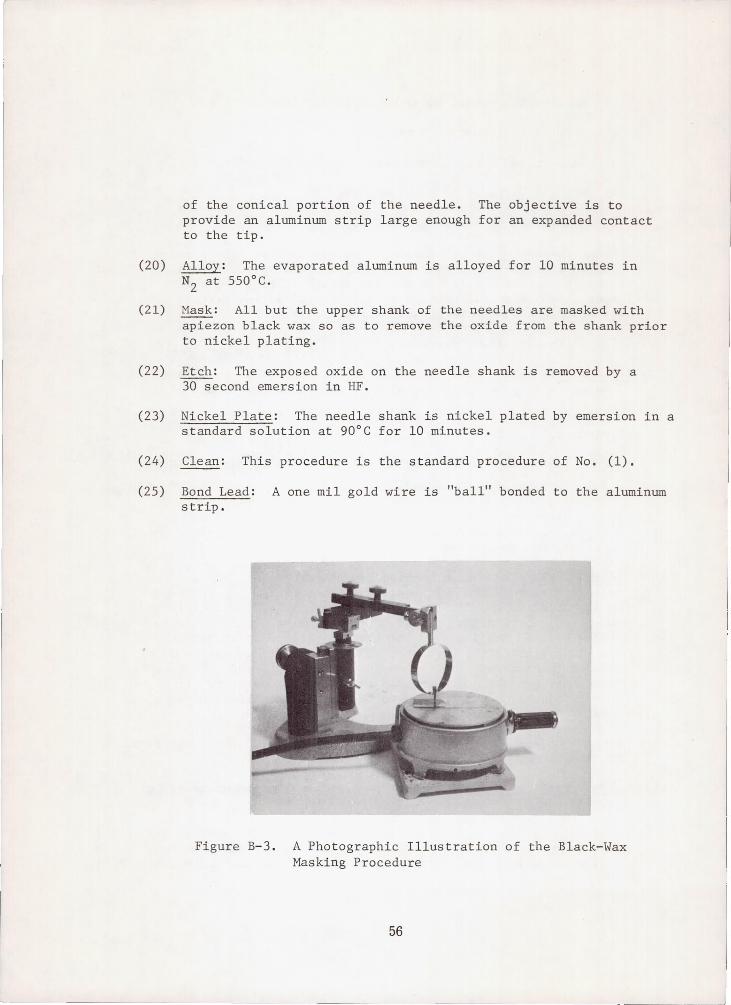
of the conical portion of the needle. The objective is to provide an aluminum strip large enough for an expanded contact to the tip.
(20) Alloy: The evaporated aluminum is alloyed for 10 minutes in N2 at 550°C.
(21) Mask: All but the upper shank of the needles are masked with apiezon black wax so as to remove the oxide from the shank prior to nickel plating.
(22) Etch: The exposed oxide on the needle shank is removed by a 30 second emersion in HF.
(23) Nickel Plate: The needle shank is nickel plated by emersion in a standard solution at 90°C for 10 minutes.
(24) Clean: This procedure is the standard procedure of No. (1).
(25) Bond Lead: A one mil gold wire is "ball" bonded to the aluminum strip.
Figure B-3. A Photographic Illustration of the Black-Wax Masking Procedure
56
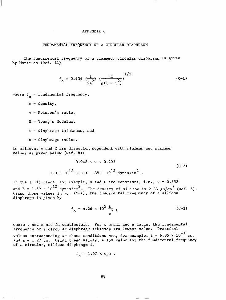
APPENDIX C
FUNDAMENTAL FREQUENCY OF A CIRCULAR DIAPHRAGM
The fundamental frequency of a clamped, circular diaphragm is given by Morse as (Ref. 11)
t E 11 2 fo = 0 . 9 3 4 (7) ( 2 ) 2a p(1 - w )
where f = fundamental frequency, 0
p = density,
v = Poisson's ratio,
E = Young's Modulus,
t = diaphragm thickness, and
a = diaphragm radius.
In silicon, v and E are direction dependent with minimum and maximum values as given below (Ref. 6 ) :
0.048 < v < 0.403
1.3 x 10l2 < E < 1.88 x 10l2 dynes/cm . (C-2)
2
In the (111) plane, for example, v and E are constants, i.e., v = 0.358 and E = 1.69 x 1OI2 dynes/cm2. The density of silicon is 2.33 grn/cm3 (Ref. 6). Using those values in Eq. (C-l), the fundamental frequency of a silicon diaphragm is given by
fo = 4.26 x lo5 5 , a
where t and a are in centimeters. For t small and a large, the fundamental frequency of a circular diaphragm achieves its lowest value. Practical values corresponding to these conditions are, for example, t = 6.35 X cm. and a = 1.27 cm. Using these values, a low value for the fundamental frequency of a circular, silicon diaphragm is
fo = 1.67 k cps .
57
I
LIST OF REFERENCES
1. R e s e a r c h T r i a n g l e I n s t i t u t e , F e a s i b i l i t y S t u d y of a Minia ture Sol id- S ta te Pressure Transducer , by C. D. Parker , Cont rac t No. NAS1-6249, Research Triangle Park, N. C . , July 1967 ( U ) .
2. J . J . Wortman, J . R . Hauser, and R. M. Burger, J. Appl. Phys. 3 5 , 2122-2131, July 1964.
3. J. J. Wortman and J. R. Hauser, J . Appl. Phys. 37, 3527-3530, August 19 66.
4. J. R . Hauser and J. J. Wortman, J . Appl. Phys. 37, 3884-3892, September 1966.
5. J . J. Wortman, E f f e c t of Mechanical Strain on p-n J u n c t i o n s , NASA CR-275, 1-106, August 1965.
6. J . J . Wortman, Semiconductor Piezojunct ion Transducers , NASA CR-1089, 1-85, June 1968.
7. R e s e a r c h T r i a n g l e I n s t i t u t e , I n t e g r a t e d S i l i c o n Device Technology Volume V----Physical/Electrical P r o p e r t i e s of S i l i c o n , by R. A. Evans, Technical Documentary Report No. ASD-TDR-63-316, Vol. V . Contract AF 33(657)-10340, burham, N . C . , Ju ly 1965 (U) AD 605.558.
8. R . J . Roark, Formulas for St re s s and S t r a in , 4 th Ed . , M c G r a w - H i l l Book Company, New York, New York (1965).
9. J . F. Cleary, Transis tor Manual , General Electric Company, Syracuse, New York, 1962.
10. W. P . Mason, Phys ica l Acous t i c s and t he P rope r t i e s of S o l i d s , (D. Van Nostrand Company, New York, 1958).
11. p. B. Morse, Vibration and Sound, 1st Ed., McGraw-Hill Book Company, New York, N. Y . (1936).
58 NASA-Langley, 1969 - 26 CH-1366