
OEM Safety and System Integration Manual - … · OEM Safety and System Integration Manual: Module...
18
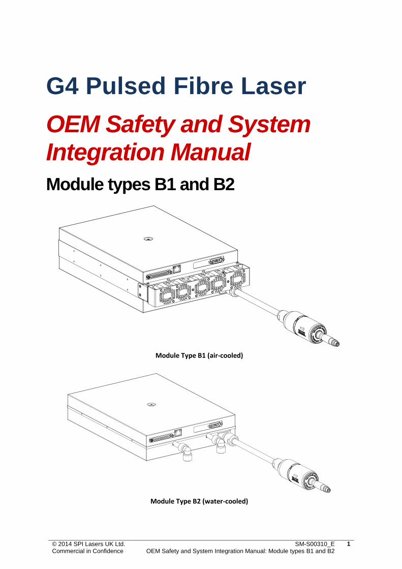
© 2014 SPI Lasers UK Ltd. Commercial in Confidence SM-S00310_E OEM Safety and System Integration Manual: Module types B1 and B2 1 G4 Pulsed Fibre Laser OEM Safety and System Integration Manual Module types B1 and B2 Module Type B1 (air-cooled) Module Type B2 (water-cooled)
Transcript of OEM Safety and System Integration Manual - … · OEM Safety and System Integration Manual: Module...
© 2014 SPI Lasers UK Ltd. Commercial in Confidence
SM-S00310_E OEM Safety and System Integration Manual: Module types B1 and B2
1
G4 Pulsed Fibre Laser
OEM Safety and System Integration Manual
Module types B1 and B2
Module Type B1 (air-cooled)
Module Type B2 (water-cooled)
© 2014 SPI Lasers UK Ltd. Commercial in Confidence
SM-S00310_E OEM Safety and System Integration Manual: Module types B1 and B2
2
Preface
Definition of Symbols and Terms
This symbol is to alert the user to the danger to exposure of
hazardous invisible laser radiation
This symbol is to emphasize important information regarding
installation points or operating procedures
DANGER: Describes hazards that could directly or indirectly lead to serious
personal injury or death.
WARNING: Describes hazards or practices that could directly or indirectly lead
to serious personal injury or death.
CAUTION: Describes hazards or practices that could lead to minor personal
injury or product damage.
LASER
INTEGRATOR
Any person that integrates the laser into their equipment, or any
person who uses the laser in the form as supplied by SPI.
PRODUCT The definition of “Product” as used herein means the item that was
procured from SPI Lasers UK Limited. The Product is sold ready
for use for its intended purpose as a laser component for
incorporation.
Document References
Please refer to the Product Specification and the Laser Interface Manual appropriate to your SPI G4
laser for functional specifications and instruction on laser control and electrical interfaces.
Document number Description
SM-S00360 G4 V8 control interface manual
SM-S00220 G4 accessories datasheet
CSE00106 Tech Note: G4 ILLK Protective Green Tape Warning
CSE00081 Tech Note: G4 ILLK Safe De-Focus Operating Limits
© 2014 SPI Lasers UK Ltd. Commercial in Confidence
SM-S00310_E OEM Safety and System Integration Manual: Module types B1 and B2
3
Warnings
WARNING: If the fibre laser described in this manual is used in a
manner not specified by SPI Lasers UK Ltd, the protection
provided by the equipment may be impaired.
WARNING: Attempts to modify or alter the product, or the use of
controls, adjustments or performance of procedures other than
those specified herein may result in hazardous radiation
exposure.
CAUTION: Modifications to the product or the use of controls or
adjustments or performance of procedures other than those
specified herein:
will invalidate the warranty
may result in patent infringement
Laser Integrators are not authorized to modify the specification of the Product.
Licensing
This product carries no license by IMRA America, Inc. for pulsed operation less than 100ps.
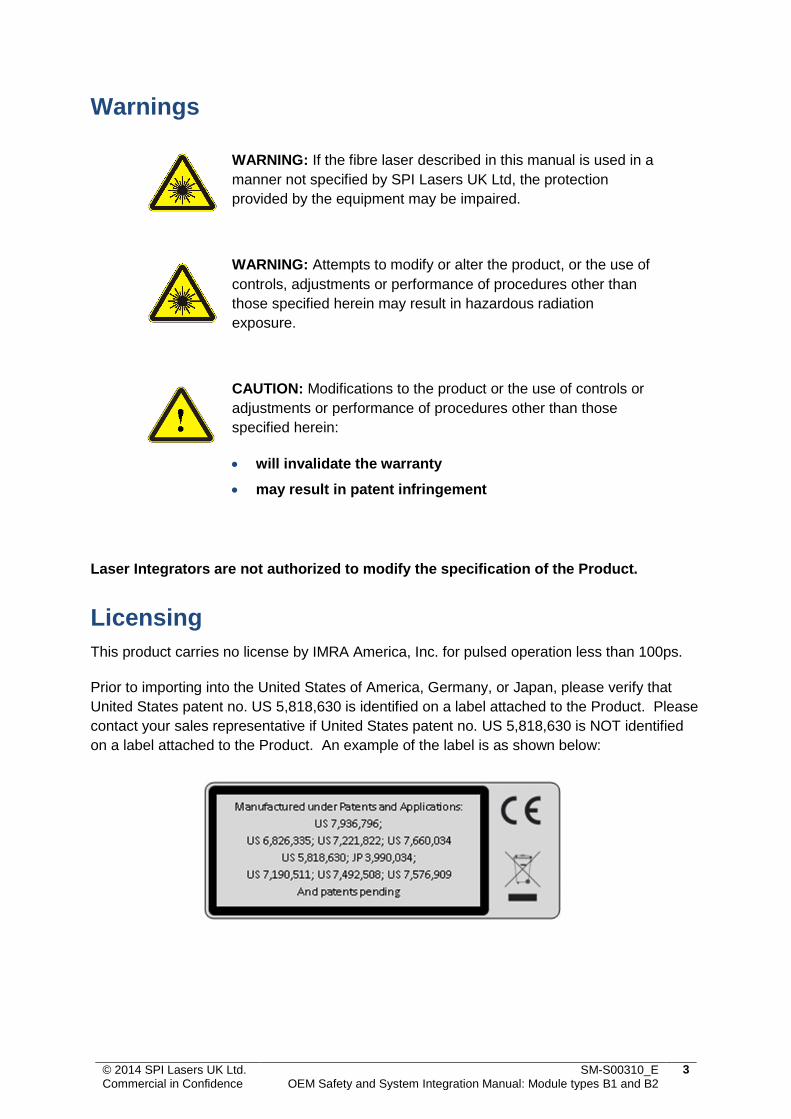
Prior to importing into the United States of America, Germany, or Japan, please verify that
United States patent no. US 5,818,630 is identified on a label attached to the Product. Please
contact your sales representative if United States patent no. US 5,818,630 is NOT identified
on a label attached to the Product. An example of the label is as shown below:
© 2014 SPI Lasers UK Ltd. Commercial in Confidence
SM-S00310_E OEM Safety and System Integration Manual: Module types B1 and B2
4
Table of Contents Preface 2
Definition of Symbols and Terms 2
Document References 2
Warnings 3
Licensing 3
1 Laser Safety 5
1.1 Laser Hazard Information 5
1.2 Protective Eyewear 5
1.3 Laser Safety on Installation 6
1.4 Laser Safety under Ethernet Control 7
1.5 Laser Safety Labeling 8
2 Compliance 9
2.1 Compliance 9
2.2 RoHS Directive Compliance 10
2.3 WEEE Directive Compliance 10
2.4 Compliance Labeling 10
3 Electrical Integration Details 11
3.1 Safety Warning 11
3.2 Location of Connectors 11
3.3 Earth Bonding 11
3.4 Power Connector 12
4 Mechanical Integration Details 13
4.1 Top View and Label Locations 13
4.2 Front View, Cable Locations and Earth Stud Label 14
4.3 Beam Delivery Optic (ILLK) Dimensions and Labeling 15
4.4 Side View and Mounting Hole Location 16
4.5 Mass of Laser Modules and ILLK 16
5 Environmental and Cooling Details 17
5.1 Air-Cooled Laser Installation Requirements 17
5.2 Water-Cooled Laser Installation Requirements 18
© 2014 SPI Lasers UK Ltd. Commercial in Confidence
SM-S00310_E OEM Safety and System Integration Manual: Module types B1 and B2
5
1 Laser Safety
1.1 Laser Hazard Information
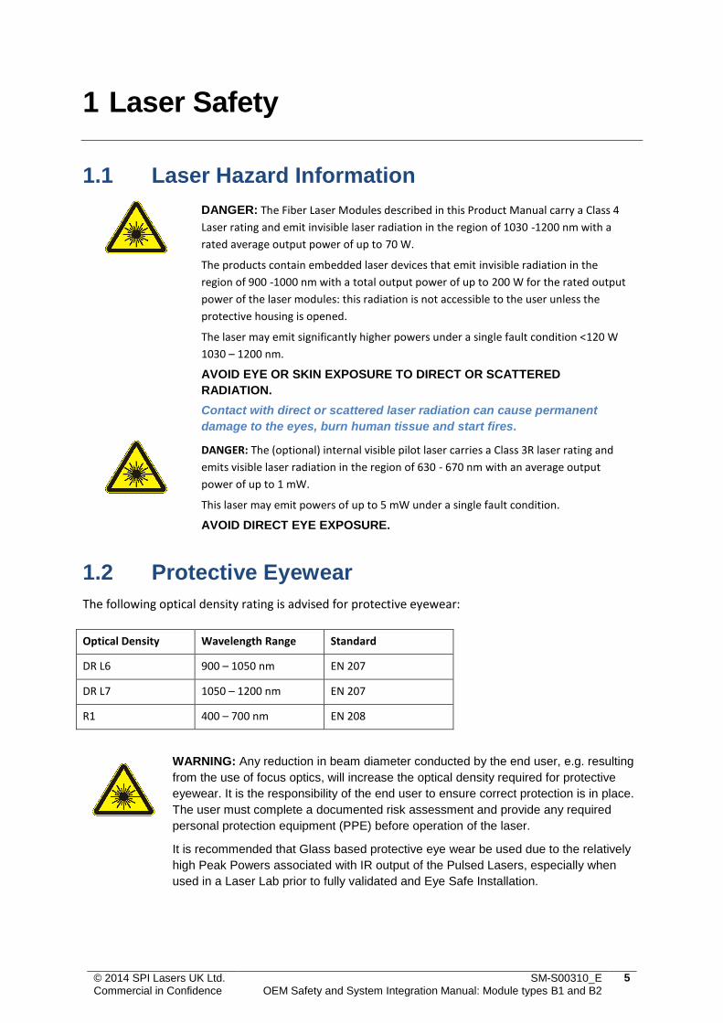
DANGER: The Fiber Laser Modules described in this Product Manual carry a Class 4
Laser rating and emit invisible laser radiation in the region of 1030 -1200 nm with a
rated average output power of up to 70 W.
The products contain embedded laser devices that emit invisible radiation in the
region of 900 -1000 nm with a total output power of up to 200 W for the rated output
power of the laser modules: this radiation is not accessible to the user unless the
protective housing is opened.
The laser may emit significantly higher powers under a single fault condition <120 W
1030 – 1200 nm.
AVOID EYE OR SKIN EXPOSURE TO DIRECT OR SCATTERED
RADIATION.
Contact with direct or scattered laser radiation can cause permanent
damage to the eyes, burn human tissue and start fires.
DANGER: The (optional) internal visible pilot laser carries a Class 3R laser rating and
emits visible laser radiation in the region of 630 - 670 nm with an average output
power of up to 1 mW.
This laser may emit powers of up to 5 mW under a single fault condition.
AVOID DIRECT EYE EXPOSURE.
1.2 Protective Eyewear
The following optical density rating is advised for protective eyewear:
Optical Density Wavelength Range Standard
DR L6 900 – 1050 nm EN 207
DR L7 1050 – 1200 nm EN 207
R1 400 – 700 nm EN 208
WARNING: Any reduction in beam diameter conducted by the end user, e.g. resulting
from the use of focus optics, will increase the optical density required for protective
eyewear. It is the responsibility of the end user to ensure correct protection is in place.
The user must complete a documented risk assessment and provide any required
personal protection equipment (PPE) before operation of the laser.
It is recommended that Glass based protective eye wear be used due to the relatively
high Peak Powers associated with IR output of the Pulsed Lasers, especially when
used in a Laser Lab prior to fully validated and Eye Safe Installation.

© 2014 SPI Lasers UK Ltd. Commercial in Confidence
SM-S00310_E OEM Safety and System Integration Manual: Module types B1 and B2
6
1.3 Laser Safety on Installation
This product is a Class 4 OEM laser product specifically designed for incorporation or integration into
other equipment. As such, it DOES NOT MEET the full requirements for a stand-alone laser system as
defined by 21 CFR 1040.10 and IEC/EN 60825-1:2007.
During installation it is vital that the laser hazard is fully managed. In particular, the laser integrator is
required to provision the engineering requirements detailed in IEC/EN 60825-1. These include, but are
not limited to:
Provision of a protective housing which prevents human access to laser radiation in excess of
the Accessible Emission Limit (AEL) for Class 1 (see section 4.2 detailed in IEC/EN 60825-1).
The beam delivery cable is not Class 1 under a worst-case single fault, no cable break or fibre
break detection is offered on this product. The integrator must either include the beam
delivery cable inside the Class 1 enclosure with the Pulsed Laser Aperture or undertake
suitable measures to ensure that under reasonable and foreseeable use, the cable is suitably
positioned to prevent it from becoming damaged or mishandled.
The beam delivery cable has not been designed for robotic applications. The Laser must not be
designed into systems where the Beam Delivery Cable will be subject to high levels of
acceleration, torsion and twist, or combination thereof. If this is a requirement for the
integration please contact SPI to discuss the application in more detail.
Provision of a remote interlock connector which, when open-circuited, prevents access to
laser radiation in excess of Class 1M (section 4.4 detailed in IEC/EN 60825-1).
Provision of a manual reset function to enable resumption of accessible Class 4 laser radiation
emission after interruption of emission caused by use of the remote interlock connector or an
interruption of longer than 5s of electrical mains power (section 4.5 detailed in IEC/EN 60825-
1).
Provision of a key-operated master control. The key should be removable and the laser
radiation shall not be accessible when the key is removed (section 4.6 detailed in IEC/EN
60825-1).
Provision of a fail-safe or redundant audible or visible emission indicator. This should be
repeated at the laser aperture if it is located more than 2m from the original emission
indicator (section 4.7 detailed in IEC/EN 60825-1).
Provision of a beam stop or attenuator is permanently attached to prevent access to laser
radiation in excess of Class 1M (section 4.8 detailed in IEC/EN 60825-1).
If the laser module has the optional internal, visible Pilot Laser, it is vital that the laser integrator
ensures that the laser hazard is fully managed. In particular, the laser integrator is required to
provision the engineering requirements detailed in IEC/EN 60825-1. Be aware that the visible Pilot
Laser carries a Class 3R eye safety rating and as such SPI recommends use of suitable safety goggles as
detailed in section 1.2.
If the enclosure in which the laser is mounted is opened, the interlock must interrupt the IR but not
necessarily the Pilot Laser, under this condition the enclosure is classed as a 3R Laser Product and
should be labeled so.

© 2014 SPI Lasers UK Ltd. Commercial in Confidence
SM-S00310_E OEM Safety and System Integration Manual: Module types B1 and B2
7
i.e. for the Laser to be considered Class3R, the selection of the Pilot Laser must physically interrupt
the 24V Laser Diode Supply, to prevent any IR emission under a single fault condition (see manual).
The pilot laser operates from the 24V logic supply so will still function. See manual for the pin
allocation for the diode and logic 24V power supplies.
It is the Integrators responsibility to provide the engineering requirements to meet section 4.0 of
IEC/EN 60825-1. Review this section for guidance on compliance.
WARNING: Take care when in close proximity to the beam delivery optic (ILLK) - HIGH
MAGNETIC FIELDS MAY BE PRESENT. PACEMAKERS OR OTHER SIMILAR
IMPLANTED DEVICES MAY BE AFFECTED
1.4 Laser Safety under Ethernet Control
WARNING: It is possible for multiple users to connect to and control a G4 laser simultaneously via the Ethernet port. The laser will respond to each command in the order in which it is received and does not differentiate between commands sent from different Ethernet controllers.
Care should be taken especially when controlling the laser remotely across a network as another user could be working with the laser.
It is the Integrators responsibility to ensure that any remote connectivity to the Laser cannot inadvertently allow the Laser IR to be enabled during the Integration process when, IR, Pilot Laser and interlock systems are being installed.
We recommend that any user intending to control the laser via Ethernet, remotely across a network should first check that the laser is installed in an interlocked, Class 1 enclosure.
© 2014 SPI Lasers UK Ltd. Commercial in Confidence
SM-S00310_E OEM Safety and System Integration Manual: Module types B1 and B2
8
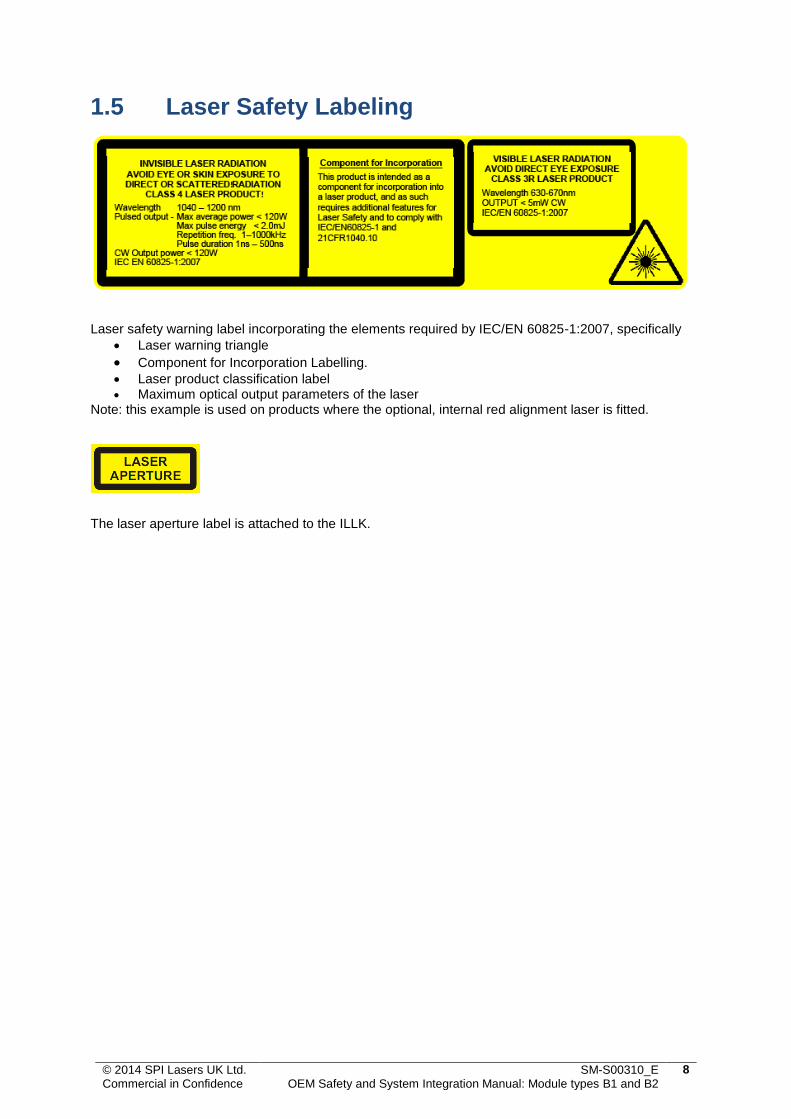
1.5 Laser Safety Labeling
Laser safety warning label incorporating the elements required by IEC/EN 60825-1:2007, specifically
Laser warning triangle
Component for Incorporation Labelling. Laser product classification label Maximum optical output parameters of the laser
Note: this example is used on products where the optional, internal red alignment laser is fitted.
The laser aperture label is attached to the ILLK.

© 2014 SPI Lasers UK Ltd. Commercial in Confidence
SM-S00310_E OEM Safety and System Integration Manual: Module types B1 and B2
9
2 Compliance
2.1 Compliance
CAUTION: - If the laser is used in a manner not specified by the
manufacturer, the protections incorporated may be impaired and the
warranty will be void.
The product is specifically designed as an OEM, low-voltage, DC-powered laser device for
incorporation or integration into other equipment and has a requirement for a current-controlled
power supply for incorporation within a Finished Laser System.
As such, it DOES NOT MEET the full requirements for a stand-alone laser system as defined by IEC/EN
60825-1 and 21 CFR 1040.10 under the Radiation Control for Health and Safety Act of 1968.
It is the responsibility of the equipment manufacturer to meet all of the regulatory requirements for
the final system. Nonetheless, the module has been labeled to facilitate final system compliance with
regulatory requirements.
The product is CE marked and is compliant with the requirements of the EMC Directive 2004/108/EC if
used and installed according to the recommendations in this document. The laser module and its
cables have been designed as a product for incorporation into equipment that operate in industrial or
light industrial environments against the following standards.
Standard Specifics
EN 61010-1:2001 Safety requirements for electrical equipment for measurement, control and laboratory use - Part 1: General requirements
EN61000-6-2:2005 Immunity for industrial environments (2, 3)
EN61000-6-4:2007 Emissions for industrial environments
FCC Part 15 Emissions (Class A)
IEC 61000-4-2 ESD 4kV Contact Discharge
IEC 61000-4-2 ESD 8kV Air Discharge
1. Pass with Ferrites detailed on the G4 Accessory sheet. 2. Pass with Shielded Diode and Logic PSU cable accessory. With standard, unshielded
cable G4 passed at <7 V/m. 3. Tests were carried out using a shielded 5m Cat5e RJ45 STP patch lead.
SPI recommends the use of a power supply incorporating reinforced (double) insulation rated to a
withstand voltage level of 3 kV AC. Alternative electrical power supply configurations are possible. For
the laser product integration in an industrial environment, the selected power supply should be
compatible with the intended environment and additional screening may be required to meet the
applicable EMC standards. Suitable signal cables of length less than 3m should be used.
© 2014 SPI Lasers UK Ltd. Commercial in Confidence
SM-S00310_E OEM Safety and System Integration Manual: Module types B1 and B2
10
2.2 RoHS Directive Compliance
This product is RoHS compliant in accordance with Directive 2002/95/EC on the restriction of the use
of certain hazardous substances in electrical and electronic equipment.
2.3 WEEE Directive Compliance
This logo is incorporated in SPI’s laser module labeling. It indicates that, at end of life, this
product should be separately collected from unsorted waste with a view to meeting the
recovery and recycling targets specified in the appropriate national regulations
implementing “Directive 2002/96/EC on waste electrical and electronic equipment (WEEE)”
for a product of its class.
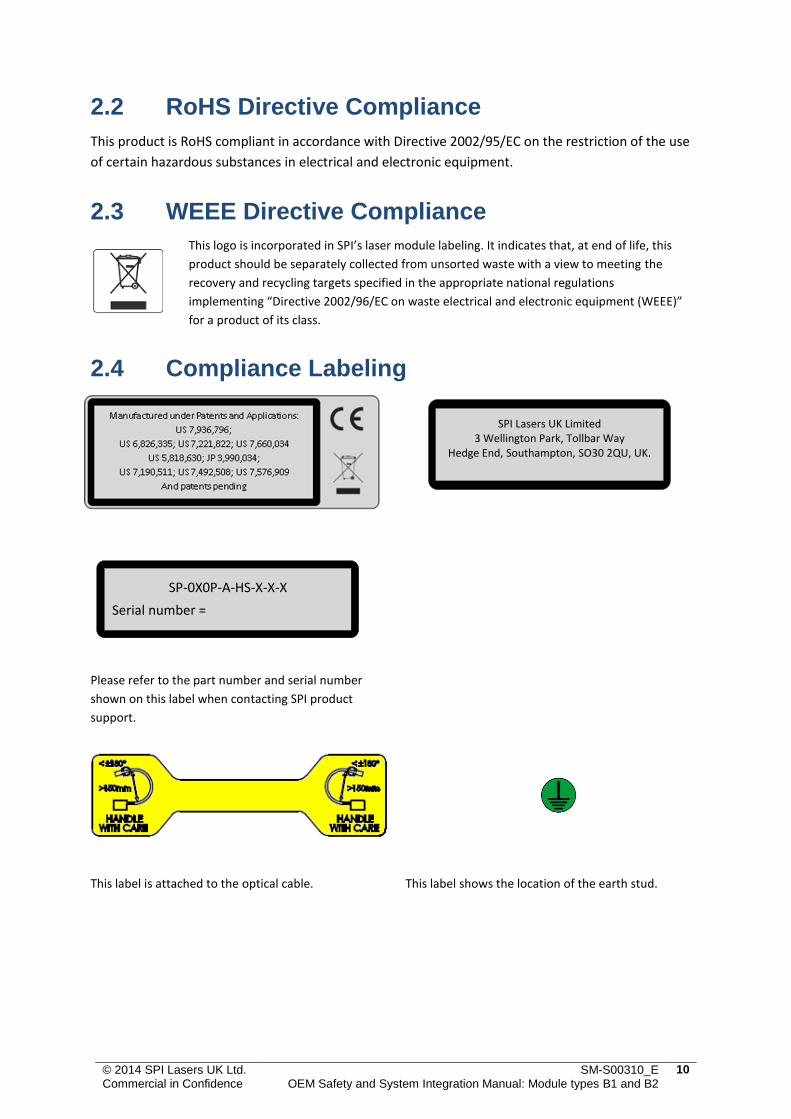
2.4 Compliance Labeling
Please refer to the part number and serial number
shown on this label when contacting SPI product
support.
This label is attached to the optical cable. This label shows the location of the earth stud.
SPI Lasers UK Limited 3 Wellington Park, Tollbar Way
Hedge End, Southampton, SO30 2QU, UK.
SP-0X0P-A-HS-X-X-X
Serial number =
© 2014 SPI Lasers UK Ltd. Commercial in Confidence
SM-S00310_E OEM Safety and System Integration Manual: Module types B1 and B2
11
3 Electrical Integration Details
3.1 Safety Warning
WARNING: Connecting the Laser module to non-isolated (active) power supplies and with unspecified control-line states could lead to uncontrolled Laser emission with the associated risk of personal exposure to hazardous radiation and product damage.
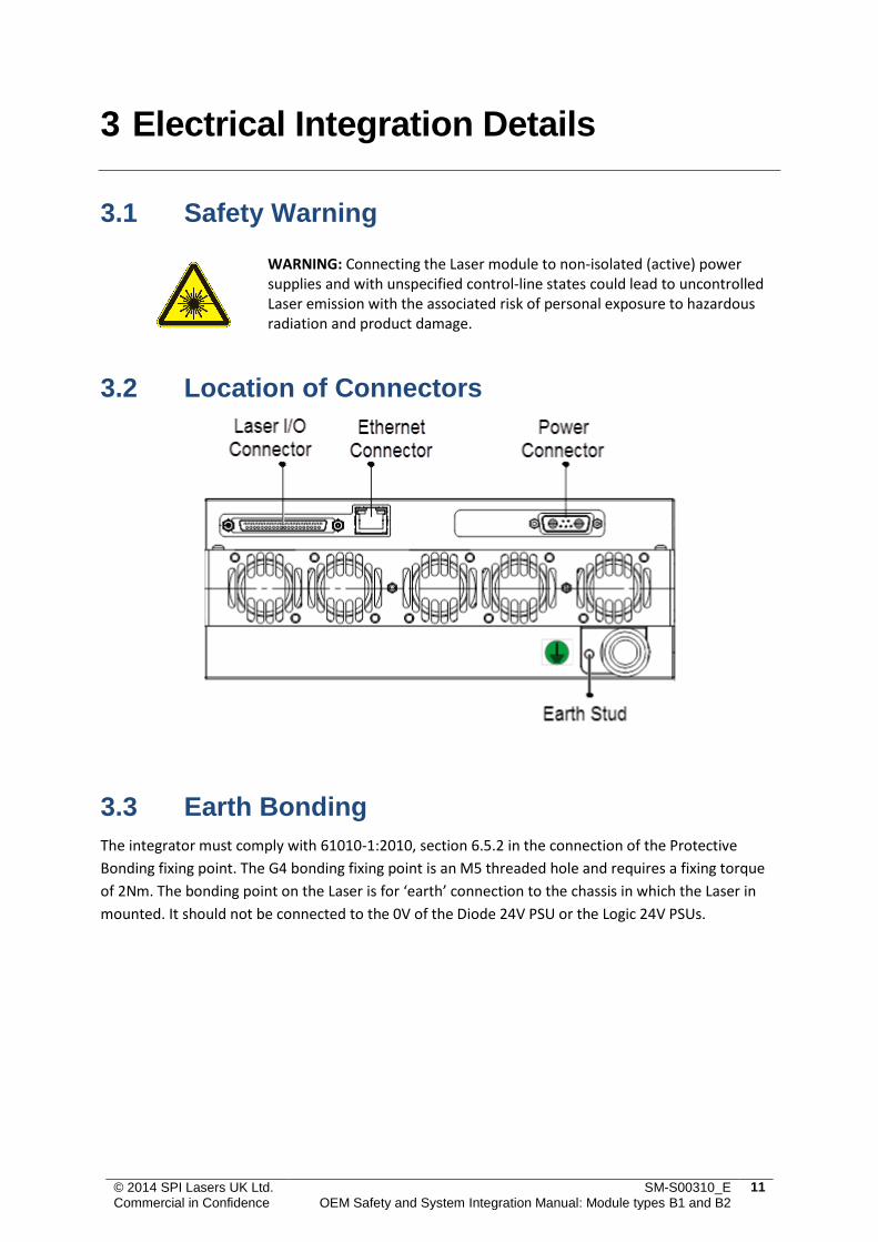
3.2 Location of Connectors
3.3 Earth Bonding
The integrator must comply with 61010-1:2010, section 6.5.2 in the connection of the Protective
Bonding fixing point. The G4 bonding fixing point is an M5 threaded hole and requires a fixing torque
of 2Nm. The bonding point on the Laser is for ‘earth’ connection to the chassis in which the Laser in
mounted. It should not be connected to the 0V of the Diode 24V PSU or the Logic 24V PSUs.
© 2014 SPI Lasers UK Ltd. Commercial in Confidence
SM-S00310_E OEM Safety and System Integration Manual: Module types B1 and B2
12
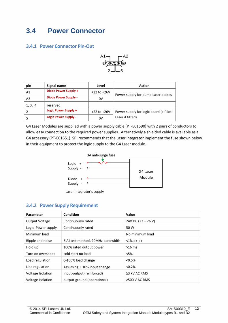
3.4 Power Connector
3.4.1 Power Connector Pin-Out
pin Signal name Level Action
A1 Diode Power Supply + +22 to +26V Power supply for pump Laser diodes
A2 Diode Power Supply - 0V
1, 3, 4 reserved
2 Logic Power Supply + +22 to +26V Power supply for logic board (+ Pilot
Laser if fitted) 5 Logic Power Supply - 0V
G4 Laser Modules are supplied with a power supply cable (PT-E01590) with 2 pairs of conductors to
allow easy connection to the required power supplies. Alternatively a shielded cable is available as a
G4 accessory (PT-E01651). SPI recommends that the Laser integrator implement the fuse shown below
in their equipment to protect the logic supply to the G4 Laser module.
3.4.2 Power Supply Requirement
Parameter Condition Value
Output Voltage Continuously rated 24V DC (22 – 26 V)
See product specification for required current Logic Power supply Continuously rated 50 W
Minimum load No minimum load
Ripple and noise EIAJ test method, 20MHz bandwidth <1% pk-pk
Hold up 100% rated output power >16 ms
Turn on overshoot cold start no load <5%
Load regulation 0-100% load change <0.5%
Line regulation Assuming 10% input change <0.2%
Voltage Isolation input-output (reinforced) ≥3 kV AC RMS
Voltage Isolation output-ground (operational) ≥500 V AC RMS
Logic + Supply -
Diode + Supply -
G4 Laser
Module
Laser Integrator’s supply
3A anti-surge fuse
A2A1
2 5
© 2014 SPI Lasers UK Ltd. Commercial in Confidence
SM-S00310_E OEM Safety and System Integration Manual: Module types B1 and B2
13
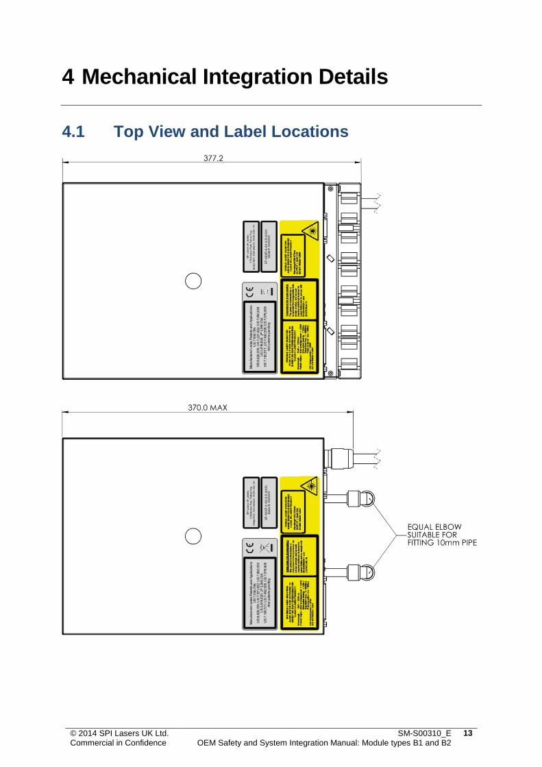
4 Mechanical Integration Details
4.1 Top View and Label Locations

© 2014 SPI Lasers UK Ltd. Commercial in Confidence
SM-S00310_E OEM Safety and System Integration Manual: Module types B1 and B2
14
4.2 Front View, Cable Locations and Earth Stud
Label
© 2014 SPI Lasers UK Ltd. Commercial in Confidence
SM-S00310_E OEM Safety and System Integration Manual: Module types B1 and B2
15
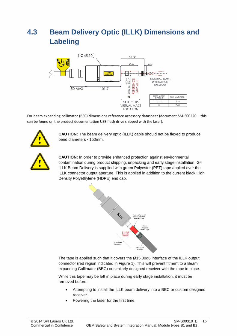
4.3 Beam Delivery Optic (ILLK) Dimensions and
Labeling
For beam expanding collimator (BEC) dimensions reference accessory datasheet (document SM-S00220 – this
can be found on the product documentation USB flash drive shipped with the laser).
CAUTION: The beam delivery optic (ILLK) cable should not be flexed to produce
bend diameters <150mm.
CAUTION: In order to provide enhanced protection against environmental
contamination during product shipping, unpacking and early stage installation, G4
ILLK Beam Delivery is supplied with green Polyester (PET) tape applied over the
ILLK connector output aperture. This is applied in addition to the current black High
Density Polyethylene (HDPE) end cap.
The tape is applied such that it covers the Ø15.00g6 interface of the ILLK output
connector (red region indicated in Figure 1). This will prevent fitment to a Beam
expanding Collimator (BEC) or similarly designed receiver with the tape in place.
While this tape may be left in place during early stage installation, it must be
removed before:
Attempting to install the ILLK beam delivery into a BEC or custom designed
receiver.
Powering the laser for the first time.
FIBER MODE
REFER
EN
CE
SU
RFA
CE
48.00
50 MAX
© 2014 SPI Lasers UK Ltd. Commercial in Confidence
SM-S00310_E OEM Safety and System Integration Manual: Module types B1 and B2
16
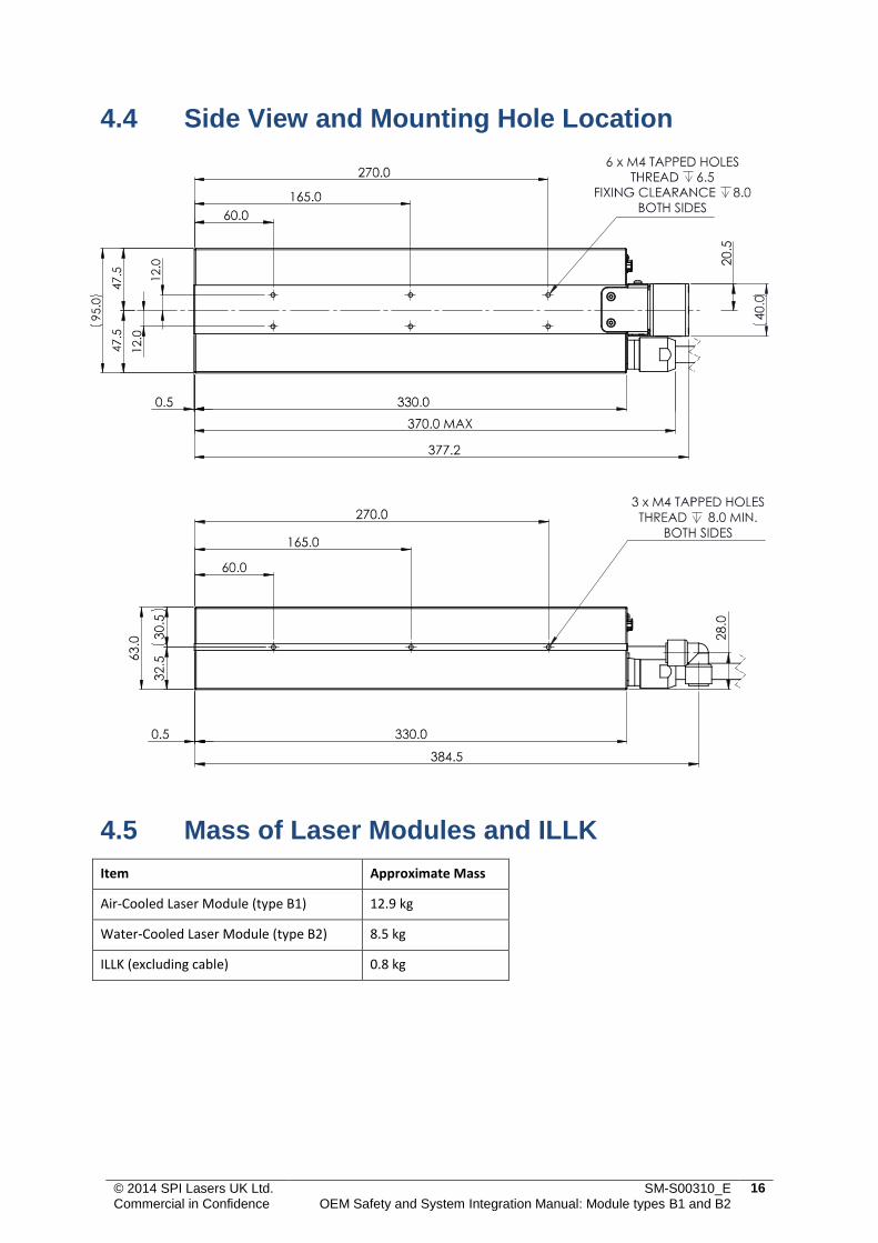
4.4 Side View and Mounting Hole Location
4.5 Mass of Laser Modules and ILLK
Item Approximate Mass
Air-Cooled Laser Module (type B1) 12.9 kg
Water-Cooled Laser Module (type B2) 8.5 kg
ILLK (excluding cable) 0.8 kg
© 2014 SPI Lasers UK Ltd. Commercial in Confidence
SM-S00310_E OEM Safety and System Integration Manual: Module types B1 and B2
17
5 Environmental and Cooling Details
5.1 Air-Cooled Laser Installation Requirements
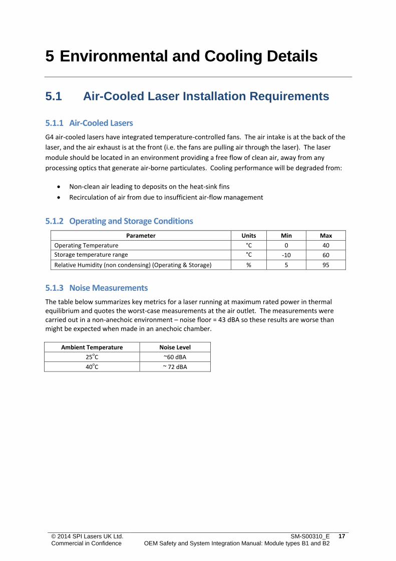
5.1.1 Air-Cooled Lasers
G4 air-cooled lasers have integrated temperature-controlled fans. The air intake is at the back of the
laser, and the air exhaust is at the front (i.e. the fans are pulling air through the laser). The laser
module should be located in an environment providing a free flow of clean air, away from any
processing optics that generate air-borne particulates. Cooling performance will be degraded from:
Non-clean air leading to deposits on the heat-sink fins
Recirculation of air from due to insufficient air-flow management
5.1.2 Operating and Storage Conditions
Parameter Units Min Max
Operating Temperature °C 0 40
Storage temperature range °C -10 60
Relative Humidity (non condensing) (Operating & Storage) % 5 95
5.1.3 Noise Measurements
The table below summarizes key metrics for a laser running at maximum rated power in thermal equilibrium and quotes the worst-case measurements at the air outlet. The measurements were carried out in a non-anechoic environment – noise floor = 43 dBA so these results are worse than might be expected when made in an anechoic chamber.
Ambient Temperature Noise Level
25oC ~60 dBA
40oC ~ 72 dBA
© 2014 SPI Lasers UK Ltd. Commercial in Confidence
SM-S00310_E OEM Safety and System Integration Manual: Module types B1 and B2
18
5.2 Water-Cooled Laser Installation Requirements
5.2.1 Water-Cooled Lasers
G4 water-cooled lasers have simple water connections to allow connection to a water-cooling circuit.
There is no flow control provided by the laser, and there is no preferred direction of water flow.
The laser must be filled and primed before being switched on. To do this:
Remove the bungs from the laser flow/return pipe fittings
Connect the chiller to the laser and open any flow valve
Switch on the chiller unit, ensuring that the water level remains
Specifications for the cooling water are tabulated below:
Parameter Units Min Max
Cooling Water Temperature Specification °C 18 32
Cooling Water Flow Rate L / min 3 7
Input Pressure bar 8
Pressure Drop bar 2
Use of de-ionised water Not permitted
5.2.2 Operating and Storage Conditions
Parameter Units Min Max
Operating Temperature – 50W °C 15 35
Storage temperature range °C 5
(-10 if blown through)
60
Relative Humidity (non condensing) (Operating & Storage) % 5 95
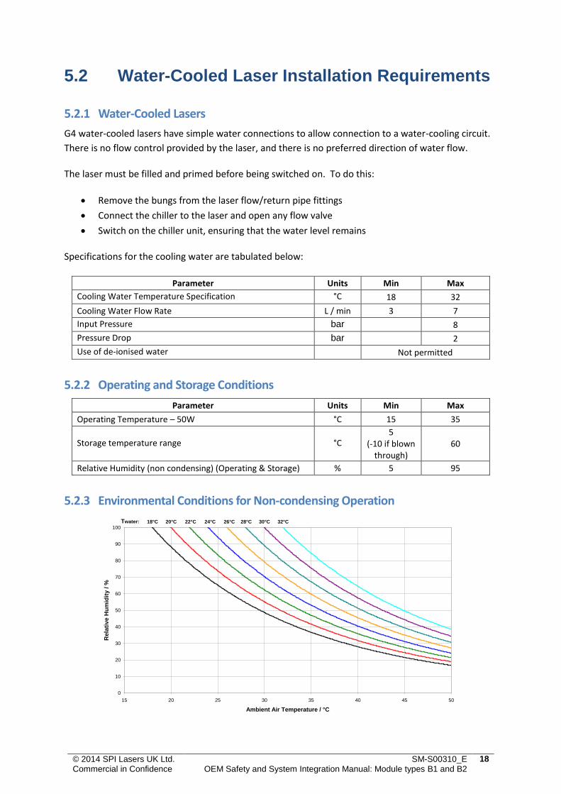
5.2.3 Environmental Conditions for Non-condensing Operation
Environmental Conditions for Non-Condensing Operation
0
10
20
30
40
50
60
70
80
90
100
15 20 25 30 35 40 45 50
Ambient Air Temperature / °C
Re
lati
ve
Hu
mid
ity
/ %
Twater: 18°C 20°C 22°C 24°C 26°C 28°C 30°C 32°C