OEM Adjustable
18
www.enidine.eu Email: [email protected] Tel.: +49 7621 98679-0 Fax: +49 7621 98679-29 17 Adjustable Series Adjustable Series Hydraulic Shock Absorbers OEM Series Overview Features and Benefits Enidine Adjustable Hydraulic Series shock absorbers offer the most flexible solutions to energy absorption application requirements when input parameters vary or are not clearly defined. By simply turning an adjustment knob, the damping force can be changed to accommodate a wide range of conditions. Enidine offers the broadest range of adjustable shock absorbers and mounting accessories in the marketplace today. The Enidine OEMXT Series provides a low profile adjustment knob offered in metric or imperial thread configurations with stroke lengths of 25 to 150 mm for drop-in competitive interchange. Low Range (LROEMXT) Series products are also available to control velocities as low as 0,08 m/s and propelling forces as high as 17 790 N. OEMXT and OEM Large Series shock absorbers are fully field repairable. • Adjustable design lets you “fine-tune” your desired damping and lock the numbered adjustment setting. • Internal orifice design provides deceleration with the most efficient damping characteristics, resulting in the lowest reaction forces in the industry. • Threaded cylinders provide mounting flexibility and increased surface area for improved heat dissipation. • Incorporated optional fluids and seal packages can expand the standard operating temperature range from (-10°C to 80°C) to (–30°C to 100°C) • ISO quality standards result in reliable, long-life operation. OEM Large Series OEM Xtreme Mid-Bore Series • Operational parameters can be expanded through the use of Enidine’s Low Range and High Performance products. • Fully field repairable units are available in mid-bore and larger bore product ranges. • Custom orificed non-adjustable units (CBOEM) can be engineered to meet specific application requirements. • A select variety of surface finishes maintains original quality appearance and provides the longest corrosion resistance protection. OEM XT OEM Small Bore Platinum Series
-
Upload
karimziani -
Category
Documents
-
view
301 -
download
14
Transcript of OEM Adjustable
www.enidine.eu Email: [email protected] Tel.: +49 7621 98679-0 Fax: +49 7621 98679-2917
Ad
just
ab
le S
eri
es
Adjustable Series Hydraulic Shock AbsorbersOEM Series
Overview
Features and Benefits
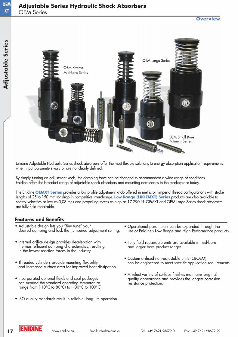
Enidine Adjustable Hydraulic Series shock absorbers offer the most flexible solutions to energy absorption application requirementswhen input parameters vary or are not clearly defined.
By simply turning an adjustment knob, the damping force can be changed to accommodate a wide range of conditions. Enidine offers the broadest range of adjustable shock absorbers and mounting accessories in the marketplace today.
The Enidine OEMXT Series provides a low profile adjustment knob offered in metric or imperial thread configurations with stroke lengths of 25 to 150 mm for drop-in competitive interchange. Low Range (LROEMXT) Series products are also available to control velocities as low as 0,08 m/s and propelling forces as high as 17 790 N. OEMXT and OEM Large Series shock absorbers are fully field repairable.
• Adjustable design lets you “fine-tune” your desired damping and lock the numbered adjustment setting.
• Internal orifice design provides deceleration with the most efficient damping characteristics, resulting in the lowest reaction forces in the industry.
• Threaded cylinders provide mounting flexibility and increased surface area for improved heat dissipation.
• Incorporated optional fluids and seal packages can expand the standard operating temperature range from (-10°C to 80°C) to (–30°C to 100°C)
• ISO quality standards result in reliable, long-life operation.
OEM Large Series
OEM Xtreme Mid-Bore Series
• Operational parameters can be expanded through the use of Enidine’s Low Range and High Performance products.
• Fully field repairable units are available in mid-bore and larger bore product ranges.
• Custom orificed non-adjustable units (CBOEM) can be engineered to meet specific application requirements.
• A select variety of surface finishes maintains original quality appearance and provides the longest corrosion resistance protection.
OEMXT
OEM Small Bore Platinum Series
A4-Metric:Project1-A4-Metric 2/13/08 8:58 AM Page 17
18www.enidine.eu Email: [email protected] Tel.: +49 7621 98679-0 Fax: +49 7621 98679-29
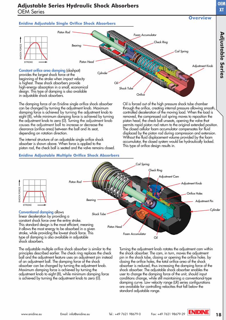
Adjustment Knob
Coil Spring
Shock Tube
Piston Head
Piston Rod
Check Ring
Orifice
Cylinder
Oil
Foam Accumulator
Bearing
Adjustment Knob
Coil Spring
Shock Tube
Piston Head
Piston Rod
Check Ring
Orifice Holes
Cylinder
OilFoam Accumulator
Adjustment Cam
Bearing Adjustment Pin
Adjustable Series Hydraulic Shock AbsorbersOEM Series
Overview
The adjustable multiple orifice shock absorber is similar to theprinciples described earlier. The check ring replaces the checkball and the adjustment feature uses an adjustment pin insteadof an adjustment ball. The damping force of the shockabsorber can be changed by turning the adjustment knob.Maximum damping force is achieved by turning the adjustment knob to eight (8), while minimum damping force is achieved by turning the adjustment knob to zero (0).
Turning the adjustment knob rotates the adjustment cam withinthe shock absorber. The cam, in turn, moves the adjustmentpin in the shock tube, closing or opening the orifice holes. byclosing the orifice holes, the total orifice area of the shockabsorber is reduced, thus increasing the damping force of theshock absorber. The adjustable shock absorber enables theuser to change the damping force of the unit, should inputconditions change, while still maintaining a conventional-typedamping curve. Low velocity range (LR) series configurationsare available for controlling velocities that fall below the standard adjustable range.
Ad
justa
ble
Serie
sOEMXT
Enidine Adjustable Single Orifice Shock Absorbers
Enidine Adjustable Multiple Orifice Shock Absorbers
The damping force of an Enidine single orifice shock absorbercan be changed by turning the adjustment knob. Maximumdamping force is achieved by turning the adjustment knob toeight (8), while minimum damping force is achieved by turningthe adjustment knob to zero (0). Turning the adjustment knobcauses the adjustment ball to increase or decrease the clearance (orifice area) between the ball and its seat, depending on rotation direction.
The internal structure of an adjustable single orifice shockabsorber is shown above. When force is applied to the piston rod, the check ball is seated and the valve remains closed.
Oil is forced out of the high pressure shock tube chamberthrough the orifice, creating internal pressure allowing smooth,controlled deceleration of the moving load. When the load is removed, the compressed coil spring moves to reposition the piston head, the check ball unseats, opening the valve that permits rapid piston rod return to the original extended position.The closed cellular foam accumulator compensates for fluid displaced by the piston rod during compression and extension.Without the fluid displacement volume provided by the foamaccumulator, the closed system would be hydraulically locked.This type of orifice design results in.
Constant orifice area damping (dashpot) provides the largest shock force at the beginning of the stroke when impact velocity is highest. These shock absorbers provide high-energy absorption in a small, economicaldesign. This type of damping is also availablein adjustable shock absorbers.
Conventional damping allows linear deceleration by providing a constant shock force over the entire stroke. This standard design is the most efficient, meaning it allows the most energy to be absorbed in a given stroke, while providing the lowest shock force. This type of damping is also available in adjustable shock absorbers.
A4-Metric:Project1-A4-Metric 2/13/08 8:58 AM Page 18
www.enidine.eu Email: [email protected] Tel.: +49 7621 98679-0 Fax: +49 7621 98679-2919
OEMXT
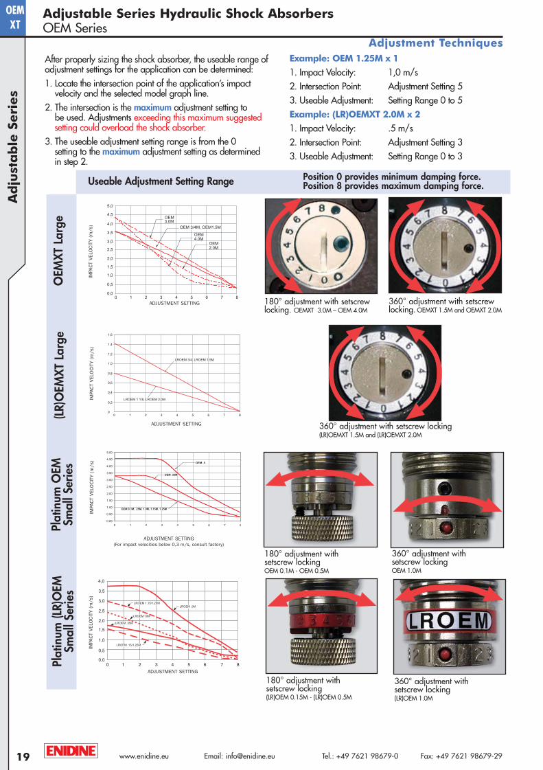
After properly sizing the shock absorber, the useable range ofadjustment settings for the application can be determined:1. Locate the intersection point of the application’s impact
velocity and the selected model graph line.2. The intersection is the maximum adjustment setting to
be used. Adjustments exceeding this maximum suggestedsetting could overload the shock absorber.
3. The useable adjustment setting range is from the 0 setting to the maximum adjustment setting as determined in step 2.
Example: OEM 1.25M x 1
1. Impact Velocity: 1,0 m/s2. Intersection Point: Adjustment Setting 53. Useable Adjustment: Setting Range 0 to 5Example: (LR)OEMXT 2.0M x 2
1. Impact Velocity: .5 m/s2. Intersection Point: Adjustment Setting 33. Useable Adjustment: Setting Range 0 to 3
(LR)
OEM
XT L
arge
OEM
XT L
arge
Position 0 provides minimum damping force.Position 8 provides maximum damping force.
360° adjustment with setscrew locking. OEMXT 1.5M and OEMXT 2.0M
Useable Adjustment Setting Range
360° adjustment with setscrew locking (LR)OEMXT 1.5M and (LR)OEMXT 2.0M
180° adjustment with setscrewlocking. OEMXT 3.0M – OEM 4.0M
Adjustable Series Hydraulic Shock AbsorbersOEM Series
Adjustment Techniques
360° adjustment with setscrew locking (LR)OEM 1.0M
180° adjustment with setscrew locking(LR)OEM 0.15M - (LR)OEM 0.5M
360° adjustment with setscrew locking OEM 1.0M
180° adjustment with setscrew locking OEM 0.1M - OEM 0.5M
Plat
inum
(LR)
OEM
Smal
l Ser
ies
Plat
inum
OEM
Smal
l Ser
ies
Ad
just
ab
le S
eri
es
ADJUSTMENT SETTING(For impact velocities below 0,3 m/s, consult factory)
IMPA
CT
VELO
CIT
Y (m
/s)
ADJUSTMENT SETTING
IMPA
CT
VELO
CIT
Y (m
/s)
ADJUSTMENT SETTING
IMPA
CT
VELO
CIT
Y (m
/s)
ADJUSTMENT SETTING
IMPA
CT
VELO
CIT
Y (m
/s)
A4-Metric:Project1-A4-Metric 2/13/08 8:59 AM Page 19
20www.enidine.eu Email: [email protected] Tel.: +49 7621 98679-0 Fax: +49 7621 98679-29
OEMXT
APPLICATION DESCRIPTIONATA
Motion Direction (Check One):
■■ Horizontal ■■ Vertical ■■ Incline
■■ Rotary Horizontal ■■ Rotary VerticalWeight (Min./Max.): __________________________________________________ (Kg)Cycle Rate ____________________________________________________ (cycles/hour)Additional Propelling Force (If known) ________________________________ (N)■■ Air Cyl: Bore ______ (mm) Max. Pressure ______(bar) Rod Dia.______(mm)■■ Hydraulic Cyl: Bore ______ (mm) Max. Pressure ______(bar)
Rod Dia.______ (mm)■■ Motor _____________ (kW) Torque _____________(Nm)Ambient Temp. ___________________________________________________________(°C)Environmental Considerations: _____________________________________________
__________________________________________________________________________________
SHOCK ABSORBER APPLICATION
Number of Shock Absorbers to Stop Load Impact Velocity (min./max.)__________________________________________ (m/s)Shock Absorber Stroke Requirements: ______________________________(mm)(a) Load Requirements _______________(m/s2)
RATE CONTROL APPLICATIONNumber of Rate Controls to Control the Load ____________________________
Control Direction: ■■ Tension (T) ■■ Compression (C)Required Stroke: __________(mm) Est. Stroke Time ______________________(s)Estimated Velocity at the Rate Control _______________________________(m/s)
Adjustable Series Hydraulic Shock AbsorbersOEM Series
Ordering Information/Application Worksheet
Ad
justa
ble
Serie
s
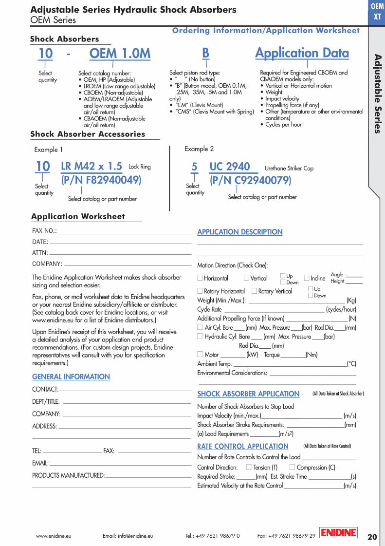
Select piston rod type:• “___” (No button)• “B” (Button model, OEM 0.1M,
.25M, .35M, .5M and 1.0Monly)• “CM” (Clevis Mount)• “CMS” (Clevis Mount with Spring)
-Select quantity
Example 1
LR M42 x 1.5 (P/N F82940049)
Select quantity
Select catalog or part number
Lock Ring
Example 2
5 UC 2940(P/N C92940079)
Select quantity
Select catalog or part number
Urethane Striker Cap
Select catalog number:• OEM, HP (Adjustable)• LROEM (Low range adjustable)• CBOEM (Non-adjustable)• AOEM/LRAOEM (Adjustable
and low range adjustable air/oil return)
• CBAOEM (Non-adjustable air/oil return)
Required for Engineered CBOEM and CBAOEM models only:• Vertical or Horizontal motion• Weight• Impact velocity• Propelling force (if any)• Other (temperature or other environmental
conditions)• Cycles per hour
Shock Absorbers
Shock Absorber Accessories
The Enidine Application Worksheet makes shock absorber sizing and selection easier.
Fax, phone, or mail worksheet data to Enidine headquartersor your nearest Enidine subsidiary/affiliate or distributor. (See catalog back cover for Enidine locations, or visit www.enidine.eu for a list of Enidine distributors.)
Upon Enidine’s receipt of this worksheet, you will receive a detailed analysis of your application and product recommendations. (For custom design projects, Enidine representatives will consult with you for specifi cation requirements.)
GENERAL INFORMATION
CONTACT:
DEPT/TITLE:
COMPANY:
ADDRESS:
TEL: FAX:
EMAIL:
PRODUCTS MANUFACTURED:
FAX NO.:
DATE:
ATTN:
COMPANY:
■■ Up■■ Down
■■ Up■■ Down
(All Data Taken at Shock Absorber)
(All Data Taken at Rate Control)
Application Worksheet
10 OEM 1.0M Application DataB
Angle _______Height _______
10
A4-Metric:Project1-A4-Metric 2/13/08 8:59 AM Page 20
www.enidine.eu Email: [email protected] Tel.: +49 7621 98679-0 Fax: +49 7621 98679-2921
OEM
Optimal FP FD(S) Velocity ET ETC Max. Max.
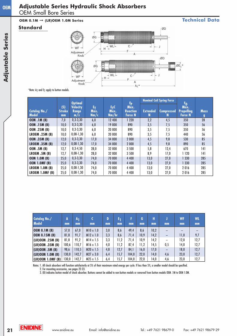
Catalog No./ Stroke Range Max. Max. Reaction Extended Compressed Propelling MassModel mm m/s Nm/c Nm/hr Force N N N Force N gOEM .1M (B) 7,0 0,3-3,30 6,0 12 400 1 220 2,2 4,5 350 28OEM .15M (B) 10,0 0,3-3,30 6,0 19 000 890 3,5 7,5 350 56OEM .25M (B) 10,0 0,3-3,30 6,0 20 000 890 3,5 7,5 350 56LROEM .25M (B) 10,0 0,08-1,30 6,0 20 000 890 3,5 7,5 440 56OEM .35M (B) 12,0 0,3-3,30 17,0 34 000 2 000 4,5 9,8 530 85LROEM .35M (B) 12,0 0,08-1,30 17,0 34 000 2 000 4,5 9,8 890 85OEM .5M (B) 12,7 0,3-4,50 28,0 32 000 3 500 5,8 12,4 670 141LROEM .5M (B) 12,7 0,08-1,30 28,0 32 000 3 500 8,9 17,0 1 120 141OEM 1.0M (B) 25,0 0,3-3,30 74,0 70 000 4 400 13,0 27,0 1 330 285OEM 1.0MF (B) 25,0 0,3-3,30 74,0 70 000 4 400 13,0 27,0 1 330 285LROEM 1.0M (B) 25,0 0,08-1,30 74,0 70 000 4 400 13,0 27,0 2 016 285LROEM 1.0MF (B) 25,0 0,08-1,30 74,0 70 000 4 400 13,0 27,0 2 016 285
Catalog No./ A A1 C D E1 F G H J WF WLModel mm mm mm mm mm mm mm mm mm mm mm
OEM 0.1M (B) 57,0 67,0 M10 x 1.0 3,0 8,6 49,4 8,6 10,2 – – –OEM 0.15M (B) 81,8 91,7 M12 x 1.0 3,3 8,6 71,4 10,9 14,2 – 11,0 9,7(LR)OEM .25M (B) 81,8 91,2 M14 x 1.5 3,3 11,2 71,4 10,9 14,2 – 12,0 12,7(LR)OEM .35M (B) 100,6 110,7 M16 x 1.5 4,0 11,2 87,4 11,2 14,5 0,5 14,0 12,7(LR)OEM .5M (B) 98,6 110,5 M20 x 1.5 4,8 12,7 84,1 16,0 17,0 – 18,0 12,7(LR)OEM 1.0M (B) 130,0 142,7 M27 x 3.0 6,4 15,7 104,0 22,0 14,0 4,6 23,0 12,7(LR)OEM 1.0MF (B) 130,0 142,7 M25 x 1.5 6,4 15,7 104,0 22,0 14,0 4,6 23,0 12,7
Ad
just
ab
le S
eri
es
Nominal Coil Spring Force
*Note: A1 and E1 apply to button models.
OEM 0.1M ➞ (LR)OEM 1.0M Series
Adjustable Series Hydraulic Shock AbsorbersOEM Small Bore Series
Technical Data
Standard
Notes: 1. All shock absorbers will function satisfactorily at 5% of their maximum rated energy per cycle. If less than 5%, a smaller model should be specified.2. For mounting accessories, see pages 22-23.3. (B) indicates button model of shock absorber. Buttons cannot be added to non-button models or removed from button models OEM .1M to OEM 1.0M.
ØD
ØE1*
ØG
H
A1*
C JF
A
WF WL
Adjustment Knob
ØD
ØG
HC J
FA
WF WL
Adjustment Knob
A4-Metric:Project1-A4-Metric 2/13/08 8:59 AM Page 21
B F
D
C
E
D
A
IK
G
J
Ø5,5
Ø5,5
Ø8,0
Ø4,5
Ø8,0
Ø4,5
B
E
HG
A
5
F
C
22www.enidine.eu Email: [email protected] Tel.: +49 7621 98679-0 Fax: +49 7621 98679-29
OEM
ØCD
CAHEX JAM NUT(NOT INCLUDED)
Ad
justa
ble
Serie
sAdjustable Series Hydraulic Shock AbsorbersOEM Small Bore Series
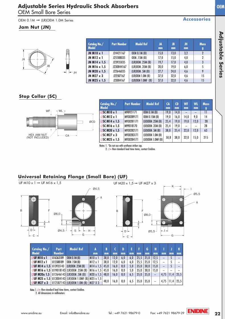
AccessoriesOEM 0.1M ➞ (LR)OEM 1.0M Series
Notes: 1. *Do not use with urethane striker cap. 2. ∅= Non-standard lead time items, contact Enidine.
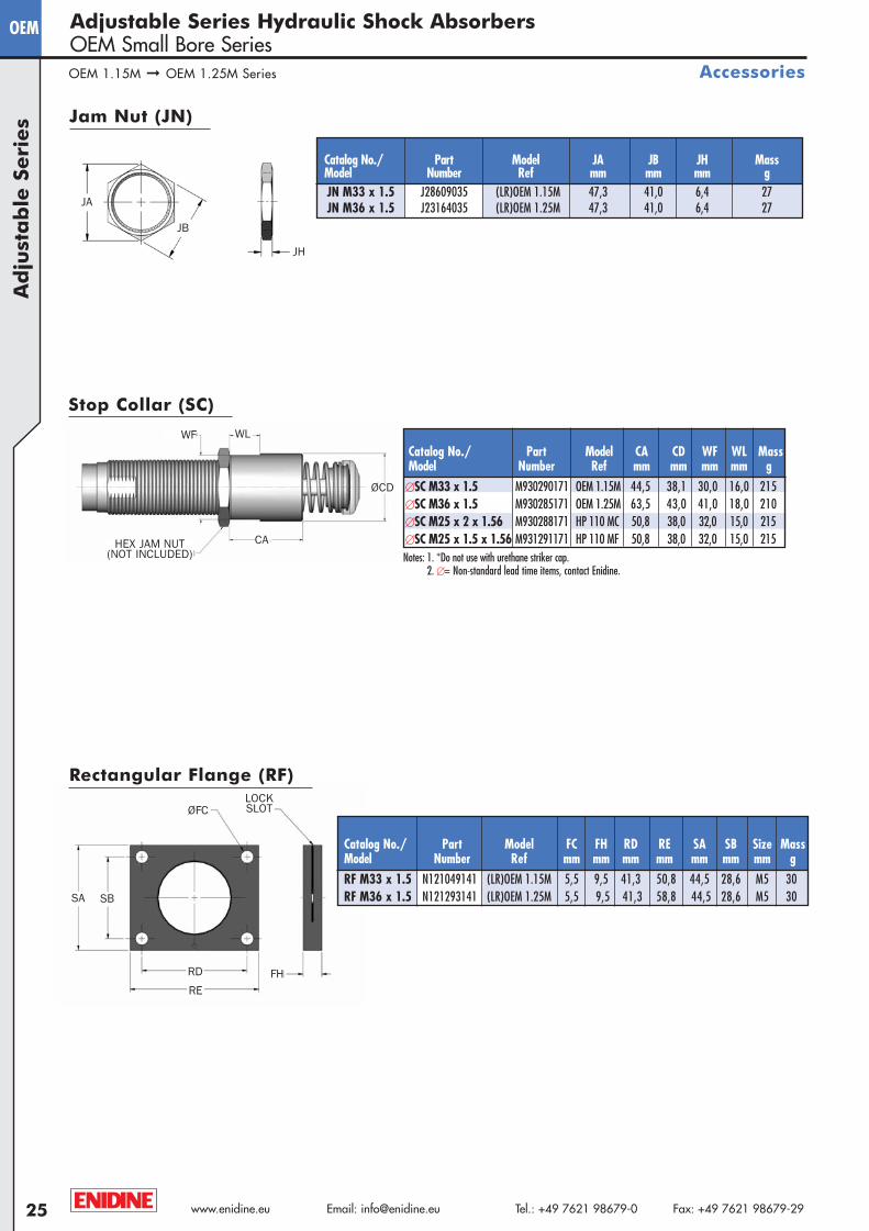
Jam Nut (JN)
JH
JB
JA
Stop Collar (SC)
UF M20 x 1,5 ➞ UF M27 x 3UF M10 x 1 ➞ UF M16 x 1,5
Universal Retaining Flange (Small Bore) (UF)
Catalog No./ Part Number Model Ref CA CD WF WL MassModel mm mm mm mm g∅SC M10 x 1 M98921171 OEM 0.1M (B) 19,0 14,0 – – 11∅SC M12 x 1 M930289171 OEM 0.15M (B) 19,0 16,0 14,0 9,0 14∅SC M14 x 1.5 M930281171 (LR)OEM .25M (B) 25,4 19,0 19,0 12,0 28∅SC M16 x 1.5 M99018170 (LR)OEM .35M (B) 25,4 19,0 – – 28∅SC M20 x 1.5 M930282171 (LR)OEM .5M (B) 38,0 25,4 22,0 12,0 63∅SC M27 x 3 M930283171 (LR)OEM 1.0M (B)
50,8 38,0 32,0 15,0 215∅SC M25 x 1.5 M930284171 (LR)OEM 1.0MF (B)
WLWF
Notes: 1. ∅= Non-standard lead time items, contact Enidine.2. All dimensions in millimeters
Catalog No./ Part Number Model Ref JA JB JH MassModel mm mm mm gJN M10 x 1 J24421167 OEM 0.1M (B) 15,0 13,0 3,2 2JN M12 x 1 J25588035 OEM .15M (B) 17,0 15,0 4,0 2JN M14 x 1.5 J23935035 (LR)OEM .25M (B) 19,7 17,0 4,0 3JN M16 x 1.5 J230844167 (LR)OEM .35M (B) 20,0 19,0 6,0 5JN M20 x 1.5 J22646035 (LR)OEM .5M (B) 27,7 24,0 4,6 9JN M27 x 3 J22587167 (LR)OEM 1.0M (B) 37,0 32,0 4,6 15JN M25 x 1.5 J23004167 (LR)OEM 1.0MF (B) 37,0 32,0 4,6 15
Catalog No./ Part Model Ref A B C D E F G H I J KModel Number mm mm mm mm mm mm mm mm mm mm mm∅UF M10 x1 U16363189 OEM 0.1M (B) M10 x 1 38,0 12,0 6,0 6,0 25,5 25,0 12,5 – 5 –∅UF M12 x1 U15588189 OEM .15M (B) M12 x 1 38,0 12,0 6,0 6,0 25,5 25,0 12,5 – 5 –∅UF M14 x 1.5 U13935143 (LR)OEM .25M (B) M14 x 1,5 45,0 16,0 8,0 5,0 35,0 30,0 15,0 – 5 –∅UF M16 x 1.5 U19018143 (LR)OEM .35M (B) M16 x 1,5 45,0 16,0 8,0 5,0 35,0 30,0 15,0 – – –∅UF M20x 1.5 U12646143 (LR)OEM .5M (B) M20 x 1,5 48,0 16,0 8,0 6,5 35,0 35,0 – 4,75 11,4 25,5∅UF M25 x 1.5 U13004143 (LR)OEM 1.0MF (B) M25 x 1,5
48,0 16,0 8,0 6,5 35,0 35,0 – 4,75 11,4 25,5∅UF M27 x 3 U12587143 (LR)OEM 1.0M (B) M27 X 3
A4-Metric:Project1-A4-Metric 4/10/08 8:43 AM Page 22
www.enidine.eu Email: [email protected] Tel.: +49 7621 98679-0 Fax: +49 7621 98679-2923
OEM
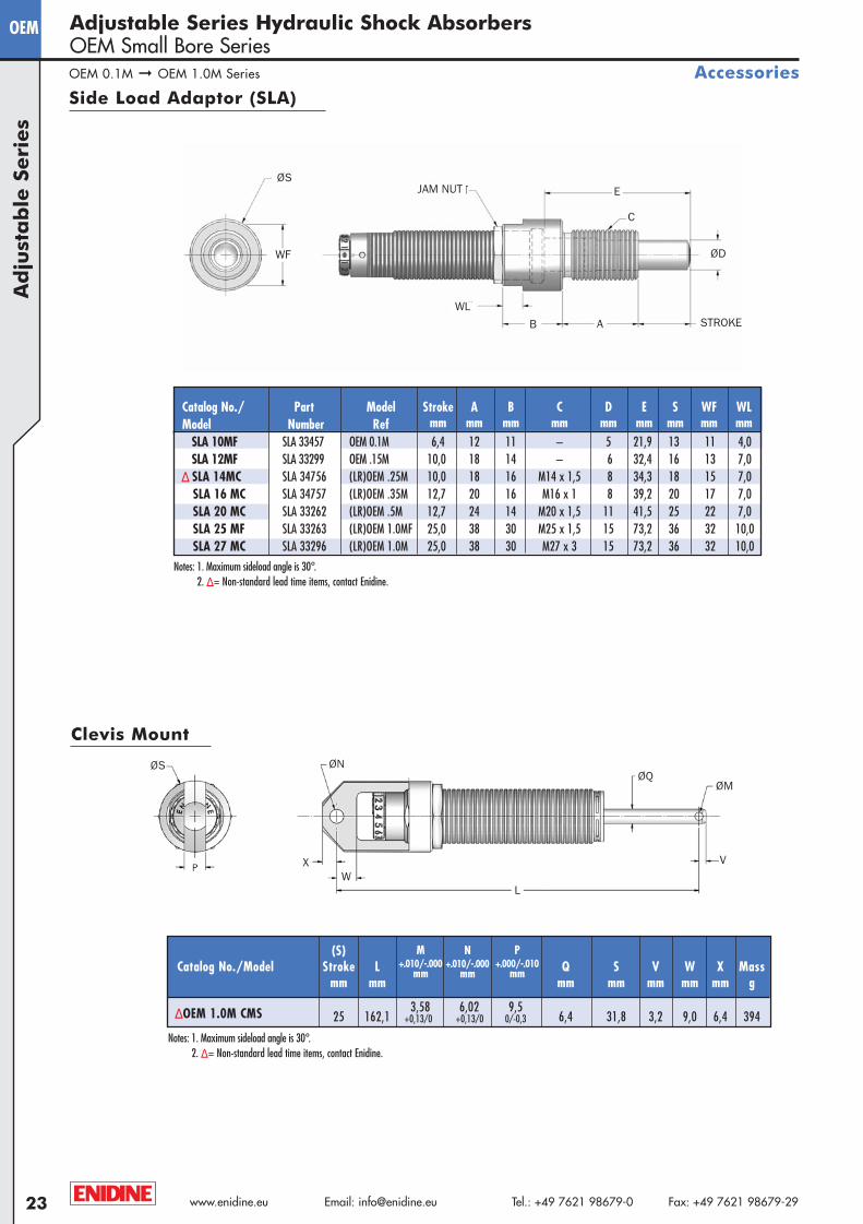
Side Load Adaptor (SLA)
Notes: 1. Maximum sideload angle is 30°. 2. Δ = Non-standard lead time items, contact Enidine.
Ad
just
ab
le S
eri
es
Adjustable Series Hydraulic Shock AbsorbersOEM Small Bore Series
Accessories
JAM NUTØS
WF
WL
B A
E
C
ØD
STROKE
(S)Catalog No./Model Stroke L Q S V W X Mass
mm mm mm mm mm mm mm g
ΔOEM 1.0M CMS 25 162,13,58 6,02 9,5
6,4 31,8 3,2 9,0 6,4 394
P+.000/-.010
mm
M+.010/-.000
mm
N+.010/-.000
mm
+0,13/0 +0,13/0 0/-0,3
Clevis Mount
ØNØQ
ØM
VW
ØS
L
OEM 0.1M ➞ OEM 1.0M Series
X
Notes: 1. Maximum sideload angle is 30°. 2. Δ = Non-standard lead time items, contact Enidine.
Catalog No./ Part Model Stroke A B C D E S WF WLModel Number Ref mm mm mm mm mm mm mm mm mm
SLA 10MF SLA 33457 OEM 0.1M 6,4 12 11 – 5 21,9 13 11 4,0SLA 12MF SLA 33299 OEM .15M 10,0 18 14 – 6 32,4 16 13 7,0
Δ SLA 14MC SLA 34756 (LR)OEM .25M 10,0 18 16 M14 x 1,5 8 34,3 18 15 7,0SLA 16 MC SLA 34757 (LR)OEM .35M 12,7 20 16 M16 x 1 8 39,2 20 17 7,0SLA 20 MC SLA 33262 (LR)OEM .5M 12,7 24 14 M20 x 1,5 11 41,5 25 22 7,0SLA 25 MF SLA 33263 (LR)OEM 1.0MF 25,0 38 30 M25 x 1,5 15 73,2 36 32 10,0SLA 27 MC SLA 33296 (LR)OEM 1.0M 25,0 38 30 M27 x 3 15 73,2 36 32 10,0
A4-Metric:Project1-A4-Metric 2/13/08 8:59 AM Page 23
24www.enidine.eu Email: [email protected] Tel.: +49 7621 98679-0 Fax: +49 7621 98679-29
OEMA
dju
stab
le Se
ries
Adjustable Series Hydraulic Shock AbsorbersOEM Small Bore Series
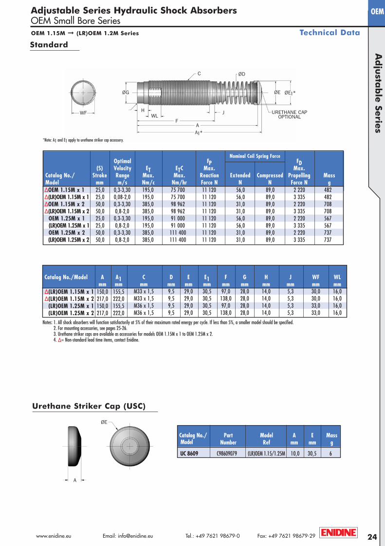
Technical DataOEM 1.15M ➞ (LR)OEM 1.2M Series
Standard
*Note: A1 and E1 apply to urethane striker cap accessory.
Nominal Coil Spring Force
Catalog No./Model A A1 C D E E1 F G H J WF WLmm mm mm mm mm mm mm mm mm mm mm mm
Δ(LR)OEM 1.15M x 1 150,0 155,5 M33 x 1,5 9,5 29,0 30,5 97,0 28,0 14,0 5,3 30,0 16,0Δ(LR)OEM 1.15M x 2 217,0 222,0 M33 x 1,5 9,5 29,0 30,5 138,0 28,0 14,0 5,3 30,0 16,0
(LR)OEM 1.25M x 1 150,0 155,5 M36 x 1,5 9,5 29,0 30,5 97,0 28,0 14,0 5,3 33,0 16,0(LR)OEM 1.25M x 2 217,0 222,0 M36 x 1,5 9,5 29,0 30,5 138,0 28,0 14,0 5,3 33,0 16,0
Notes: 1. All shock absorbers will function satisfactorily at 5% of their maximum rated energy per cycle. If less than 5%, a smaller model should be specified.2. For mounting accessories, see pages 25-26.3. Urethane striker caps are available as accessories for models OEM 1.15M x 1 to OEM 1.25M x 2.4. Δ = Non-standard lead time items, contact Enidine.
WF
C
HWL
A
J
F
A1*
ØE1*ØE
ØD
URETHANE CAPOPTIONAL
ØG
Catalog No./ Part Model A E MassModel Number Ref mm mm g
UC 8609 C98609079 (LR)OEM 1.15/1.25M 10,0 30,5 6
Urethane Striker Cap (USC)
A
ØE
Optimal FP FD(S) Velocity ET ETC Max. Max.
Catalog No./ Stroke Range Max. Max. Reaction Extended Compressed Propelling MassModel mm m/s Nm/c Nm/hr Force N N N Force N gΔOEM 1.15M x 1 25,0 0,3-3,30 195,0 75 700 11 120 56,0 89,0 2 220 482Δ(LR)OEM 1.15M x 1 25,0 0,08-2,0 195,0 75 700 11 120 56,0 89,0 3 335 482ΔOEM 1.15M x 2 50,0 0,3-3,30 385,0 98 962 11 120 31,0 89,0 2 220 708Δ(LR)OEM 1.15M x 2 50,0 0,8-2,0 385,0 98 962 11 120 31,0 89,0 3 335 708
OEM 1.25M x 1 25,0 0,3-3,30 195,0 91 000 11 120 56,0 89,0 2 220 567(LR)OEM 1.25M x 1 25,0 0,8-2,0 195,0 91 000 11 120 56,0 89,0 3 335 567OEM 1.25M x 2 50,0 0,3-3,30 385,0 111 400 11 120 31,0 89,0 2 220 737(LR)OEM 1.25M x 2 50,0 0,8-2,0 385,0 111 400 11 120 31,0 89,0 3 335 737
A4-Metric:Project1-A4-Metric 2/13/08 8:59 AM Page 24
www.enidine.eu Email: [email protected] Tel.: +49 7621 98679-0 Fax: +49 7621 98679-2925
OEM
ØCD
HEX JAM NUT(NOT INCLUDED) Notes: 1. *Do not use with urethane striker cap.
2. ∅= Non-standard lead time items, contact Enidine.
CA
JH
JB
JA
Accessories
Ad
just
ab
le S
eri
es
Adjustable Series Hydraulic Shock AbsorbersOEM Small Bore Series
Stop Collar (SC)
Jam Nut (JN)
Catalog No./ Part Model JA JB JH MassModel Number Ref mm mm mm gJN M33 x 1.5 J28609035 (LR)OEM 1.15M 47,3 41,0 6,4 27JN M36 x 1.5 J23164035 (LR)OEM 1.25M 47,3 41,0 6,4 27
Rectangular Flange (RF)
Catalog No./ Part Model FC FH RD RE SA SB Size MassModel Number Ref mm mm mm mm mm mm mm gRF M33 x 1.5 N121049141 (LR)OEM 1.15M 5,5 9,5 41,3 50,8 44,5 28,6 M5 30RF M36 x 1.5 N121293141 (LR)OEM 1.25M 5,5 9,5 41,3 58,8 44,5 28,6 M5 30
ØFC
FH
SA SB
RD
RE
LOCKSLOT
OEM 1.15M ➞ OEM 1.25M Series
WF WL
Catalog No./ Part Model CA CD WF WL MassModel Number Ref mm mm mm mm g
∅SC M33 x 1.5 M930290171 OEM 1.15M 44,5 38,1 30,0 16,0 215∅SC M36 x 1.5 M930285171 OEM 1.25M 63,5 43,0 41,0 18,0 210∅SC M25 x 2 x 1.56 M930288171 HP 110 MC 50,8 38,0 32,0 15,0 215∅SC M25 x 1.5 x 1.56 M931291171 HP 110 MF 50,8 38,0 32,0 15,0 215
A4-Metric:Project1-A4-Metric 4/10/08 8:42 AM Page 25
26www.enidine.eu Email: [email protected] Tel.: +49 7621 98679-0 Fax: +49 7621 98679-29
OEMA
dju
stab
le Se
ries
Adjustable Series Hydraulic Shock AbsorbersOEM Small Bore Series
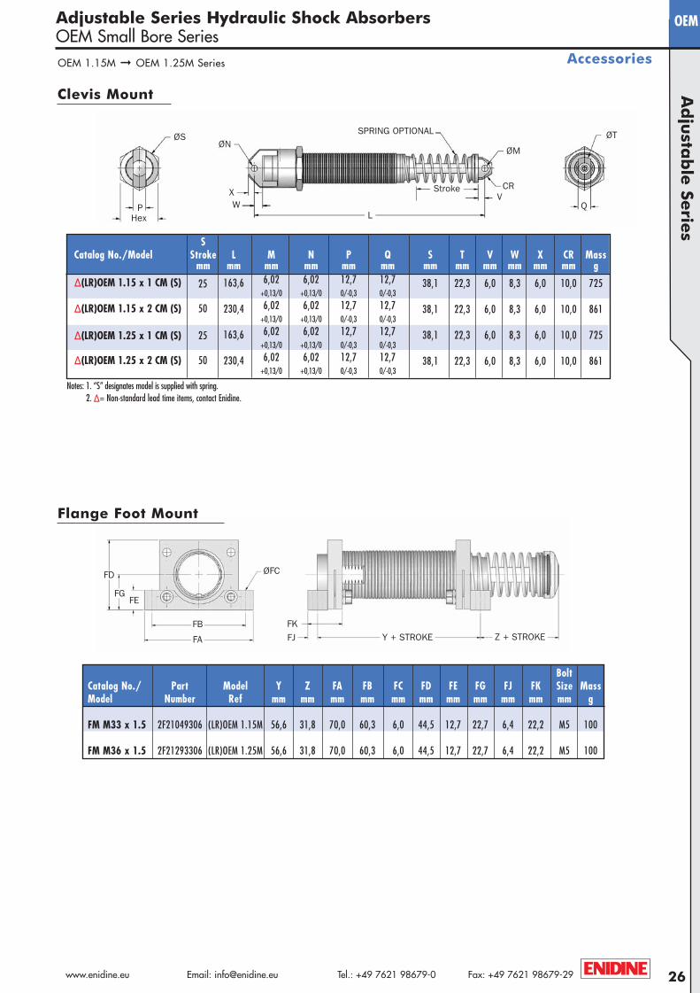
Flange Foot Mount
BoltCatalog No./ Part Model Y Z FA FB FC FD FE FG FJ FK Size MassModel Number Ref mm mm mm mm mm mm mm mm mm mm mm g
FM M33 x 1.5 2F21049306 (LR)OEM 1.15M 56,6 31,8 70,0 60,3 6,0 44,5 12,7 22,7 6,4 22,2 M5 100
FM M36 x 1.5 2F21293306 (LR)OEM 1.25M 56,6 31,8 70,0 60,3 6,0 44,5 12,7 22,7 6,4 22,2 M5 100
ØFC
FKFJFA
FB
FD
FGFE
OEM 1.15M ➞ OEM 1.25M Series Accessories
Clevis Mount
Notes: 1. “S” designates model is supplied with spring. 2. Δ = Non-standard lead time items, contact Enidine.
XW
L
VCR
P Q
ØM
ØTØN
ØS
Hex
Stroke
SPRING OPTIONAL
SCatalog No./Model Stroke L M N P Q S T V W X CR Mass
mm mm mm mm mm mm mm mm mm mm mm mm g
Δ(LR)OEM 1.15 x 1 CM (S) 25 163,6 6,02 6,02 12,7 12,7 38,1 22,3 6,0 8,3 6,0 10,0 725+0,13/0 +0,13/0 0/-0,3 0/-0,3
Δ(LR)OEM 1.15 x 2 CM (S) 50 230,4 6,02 6,02 12,7 12,7 38,1 22,3 6,0 8,3 6,0 10,0 861+0,13/0 +0,13/0 0/-0,3 0/-0,3
Δ(LR)OEM 1.25 x 1 CM (S) 25 163,6 6,02 6,02 12,7 12,7 38,1 22,3 6,0 8,3 6,0 10,0 725+0,13/0 +0,13/0 0/-0,3 0/-0,3
Δ(LR)OEM 1.25 x 2 CM (S) 50 230,4 6,02 6,02 12,7 12,7 38,1 22,3 6,0 8,3 6,0 10,0 861+0,13/0 +0,13/0 0/-0,3 0/-0,3
Y + STROKE Z + STROKE
A4-Metric:Project1-A4-Metric 2/13/08 8:59 AM Page 26
www.enidine.eu Email: [email protected] Tel.: +49 7621 98679-0 Fax: +49 7621 98679-2927
OEMXT
Ad
just
ab
le S
eri
es
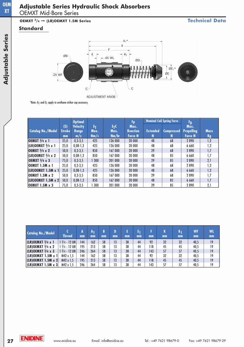
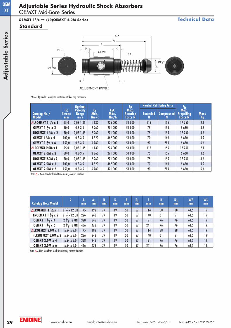
*Note: A1 and E1 apply to urethane striker cap accessory.
Adjustable Series Hydraulic Shock AbsorbersOEMXT Mid-Bore Series
Technical Data
Standard
A1*A
ØB
ØE1*
ØE
ØD
K1
F
4X WL
2X WF
ADJUSTMENT KNOB
C C
Nominal Coil Spring Force
C A A1 B D E E1 F K K1 WF WLCatalog No./ModelThread mm mm mm mm mm mm mm mm mm mm mm
(LR)OEMXT 3/4 x 1 1 3/4 - 12 UN 144 162 58 13 38 44 92 32 32 40,5 19(LR)OEMXT 3/4 x 2 1 3/4 - 12 UN 195 213 58 13 38 44 118 45 45 40,5 19(LR)OEMXT 3/4 x 3 1 3/4 - 12 UN 246 264 58 13 38 44 143 57 57 40,5 19(LR)OEMXT 1.5M x 1 M42 x 1,5 144 162 58 13 38 44 92 32 32 40,5 19(LR)OEMXT 1.5M x 2 M42 x 1,5 195 213 58 13 38 44 118 45 45 40,5 19(LR)OEMXT 1.5M x 3 M42 x 1,5 246 264 58 13 38 44 143 57 57 40,5 19
OEMXT 3/4 ➞ (LR)OEMXT 1.5M Series
Optimal Fp FD(S) Velocity ET ETC Max. Max.
Catalog No./Model Stroke Range Max. Max. Reaction Extended Compressed Propelling Massmm m/s Nm/c Nm/hr Force N N N Force N Kg
OEMXT 3/4 x 1 25,0 0,3-3,5 425 126 000 20 000 48 68 2 890 1,2(LR)OEMXT 3/4 x 1 25,0 0,08-1,3 425 126 000 20 000 48 68 6 660 1,2OEMXT 3/4 x 2 50,0 0,3-3,5 850 167 000 20 000 29 68 2 890 1,7(LR)OEMXT 3/4 x 2 50,0 0,08-1,3 850 167 000 20 000 48 85 6 660 1,7OEMXT 3/4 x 3 75,0 0,3-3,5 1 300 201 000 20 000 29 85 2 890 2,1OEMXT 1.5M x 1 25,0 0,3-3,5 425 126 000 20 000 48 68 2 890 1,2(LR)OEMXT 1.5M x 1 25,0 0,08-1,3 425 126 000 20 000 48 68 6 660 1,2OEMXT 1.5M x 2 50,0 0,3-3,5 850 167 000 20 000 29 68 2 890 1,7(LR)OEMXT 1.5M x 2 50,0 0,08-1,3 850 167 000 20 000 48 85 6 660 1,7OEMXT 1.5M x 3 75,0 0,3-3,5 1 300 201 000 20 000 29 85 2 890 2,1
A4-Metric:Project1-A4-Metric 2/13/08 8:59 AM Page 27
28www.enidine.eu Email: [email protected] Tel.: +49 7621 98679-0 Fax: +49 7621 98679-29
OEMXT
Ad
justa
ble
Serie
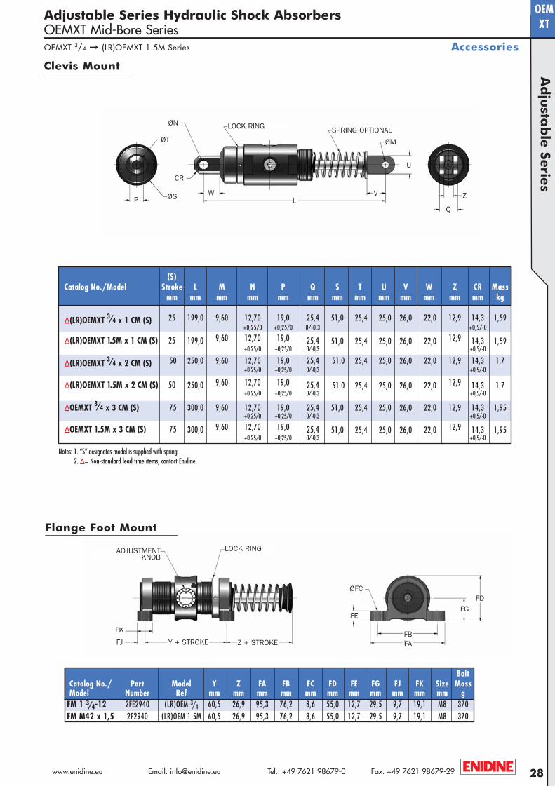
sAdjustable Series Hydraulic Shock AbsorbersOEMXT Mid-Bore Series
Accessories
Clevis Mount
Flange Foot Mount
BoltCatalog No./ Part Model Y Z FA FB FC FD FE FG FJ FK Size MassModel Number Ref mm mm mm mm mm mm mm mm mm mm mm g
FM 1 3/4-12 2FE2940 (LR)OEM 3/4 60,5 26,9 95,3 76,2 8,6 55,0 12,7 29,5 9,7 19,1 M8 370FM M42 x 1,5 2F2940 (LR)OEM 1.5M 60,5 26,9 95,3 76,2 8,6 55,0 12,7 29,5 9,7 19,1 M8 370
SPRING OPTIONALLOCK RING
ØM
ØS
ØT
CR
QP Z
LV
U
W
ØN
ØFC
FE
FAFB
FGFD
FJ
FK
LOCK RING
Z + STROKEY + STROKE
ADJUSTMENTKNOB
(S)Catalog No./Model Stroke L M N P Q S T U V W Z CR Mass
mm mm mm mm mm mm mm mm mm mm mm mm mm kg
Δ (LR)OEMXT 3/4 x 1 CM (S) 25 199,0 9,60 12,70 19,0 25,4 51,0 25,4 25,0 26,0 22,0 12,9 14,3 1,59+0,25/0 +0,25/0 0/-0,3 +0,5/-0
Δ (LR)OEMXT 1.5M x 1 CM (S) 25 199,0 9,60 12,70 19,0 25,4 51,0 25,4 25,0 26,0 22,0 12,9 14,3 1,59+0,25/0 +0,25/0 0/-0,3 +0,5/-0
Δ (LR)OEMXT 3/4 x 2 CM (S) 50 250,0 9,60 12,70 19,0 25,4 51,0 25,4 25,0 26,0 22,0 12,9 14,3 1,7+0,25/0 +0,25/0 0/-0,3 +0,5/-0
Δ (LR)OEMXT 1.5M x 2 CM (S) 50 250,0 9,60 12,70 19,0 25,4 51,0 25,4 25,0 26,0 22,0 12,9 14,3 1,7+0,25/0 +0,25/0 0/-0,3 +0,5/-0
Δ OEMXT 3/4 x 3 CM (S) 75 300,0 9,60 12,70 19,0 25,4 51,0 25,4 25,0 26,0 22,0 12,9 14,3 1,95+0,25/0 +0,25/0 0/-0,3 +0,5/-0
Δ OEMXT 1.5M x 3 CM (S) 75 300,0 9,60 12,70 19,0 25,4 51,0 25,4 25,0 26,0 22,0 12,9 14,3 1,95+0,25/0 +0,25/0 0/-0,3 +0,5/-0
OEMXT 3/4 ➞ (LR)OEMXT 1.5M Series
Notes: 1. “S” designates model is supplied with spring. 2. Δ = Non-standard lead time items, contact Enidine.
A4-Metric:Project1-A4-Metric 2/13/08 8:59 AM Page 28
www.enidine.eu Email: [email protected] Tel.: +49 7621 98679-0 Fax: +49 7621 98679-2929
OEMXT
Ad
just
ab
le S
eri
es
Adjustable Series Hydraulic Shock AbsorbersOEMXT Mid-Bore Series
Technical Data
*Note: A1 and E1 apply to urethane striker cap accessory.
Standard
Nominal Coil Spring Force
Note: Δ= Non-standard lead time items, contact Enidine.
Note: Δ= Non-standard lead time items, contact Enidine.
Optimal Fp FD(S) Velocity ET ETC Max. Max.
Catalog No./ Stroke Range Max. Max. Reaction Extended Compressed Propelling MassModel mm m/s Nm/c Nm/hr Force N N N Force N Kg
Δ LROEMXT 1 1/8 x 1 25,0 0,08-1,35 1 130 226 000 51 000 115 155 17 760 2,1OEMXT 1 1/8 x 2 50,0 0,3-3,5 2 260 271 000 51 000 75 155 6 660 3,6LROEMXT 1 1/8 x 2 50,0 0,08-1,35 2 260 271 000 51 000 75 155 17 760 3,6OEMXT 1 1/8 x 4 100,0 0,3-3,5 4 520 362 000 51 000 70 160 6 660 4,9OEMXT 1 1/8 x 6 150,0 0,3-3,5 6 780 421 000 51 000 90 284 6 660 6,4
Δ LROEMXT 2.0M x1 25,0 0,08-1,35 1 130 226 000 51 000 115 155 17 760 2,1
OEMXT 2.0M x 2 50,0 0,3-3,5 2 260 271 000 51 000 75 155 6 660 3,6
LROEMXT 2.0M x2 50,0 0,08-1,35 2 260 271 000 51 000 75 155 17 760 3,6OEMXT 2.0M x 4 100,0 0,3-3,5 4 520 362 000 51 000 70 160 6 660 4,9OEMXT 2.0M x 6 150,0 0,3-3,5 6 780 421 000 51 000 90 284 6 660 6,4
A1*A
ØB
ØE1*
ØE
ØD
K1KF
4X WL
2X WF
ADJUSTMENT KNOB
C C
OEMXT 11/8 ➞ (LR)OEMXT 2.0M Series
C A A1 B D E E1 F K K1 WF WLCatalog No./Model mm mm mm mm mm mm mm mm mm mm mm
Δ LROEMXT 1 1/8 x 1 2 1/2 - 12 UN 175 192 77 19 50 57 114 38 38 61,5 19LROEMXT 1 1/8 x 2 2 1/2 - 12 UN 226 243 77 19 50 57 140 51 51 61,5 19OEMXT 1 1/8 x 4 2 1/2 -12 UN 328 345 77 19 50 57 191 76 76 61,5 19OEMXT 1 1/8 x 6 2 1/2 -12 UN 456 473 77 19 50 57 241 76 76 61,5 19
Δ LROEMXT 2.0M x 1 M64 x 2,0 175 192 77 19 50 57 114 38 38 61,5 19(LR)OEMXT 2.0M x 2 M64 x 2,0 226 243 77 19 50 57 140 51 51 61,5 19OEMXT 2.0M x 4 M64 x 2,0 328 345 77 19 50 57 191 76 76 61,5 19OEMXT 2.0M x 6 M64 x 2,0 456 473 77 19 50 57 241 76 76 61,5 19
A4-Metric:Project1-A4-Metric 2/13/08 8:59 AM Page 29
30www.enidine.eu Email: [email protected] Tel.: +49 7621 98679-0 Fax: +49 7621 98679-29
OEMXT
ØFC
FE
FAFB
FGFD
FK
LOCK RING
Z + STROKEY + STROKE
ADJUSTMENTKNOB
Ad
justa
ble
Serie
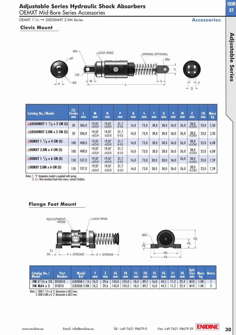
sAdjustable Series Hydraulic Shock AbsorbersOEMXT Mid-Bore Series Accessories
Accessories
Clevis Mount
Flange Foot Mount
Notes: 1. “S” designates model is supplied with spring. 2. Δ= Non-standard lead time items, contact Enidine.
BoltCatalog No./ Part Model Y Z FA FB FC FD FE FG FJ FK Size Mass NotesModel Number Ref mm mm mm mm mm mm mm mm mm mm mm kgFM 2 1/2 x 12 2FE3010 (LR)OEM 1 1/8 76,2 39,6 143,0 124,0 10,4 89,7 16,0 44,5 11,2 22,4 M10 1.08 1FM M64 x 2 2F3010 (LR)OEM 2.0M 76,2 39,6 143,0 124,0 10,4 89,7 16,0 44,5 11,2 22,4 M10 1.08 2
ØM
ØS
ØT
CR
QP ZL
V
U
W
SPRING OPTIONALLOCK RINGØN
Note: 1. OEM 1 1/8 x 6 ‘Z’ dimension is 68,3 mm.2. OEM 2.0M x 6 ‘Z’ dimension is 68,3 mm.
FJ
OEMXT 11/8 ➞ (LR)OEMXT 2.0M Series
(S)Catalog No./Model Stroke L M N P Q S T U V W Z CR Mass
mm mm mm mm mm mm mm mm mm mm mm mm mm kg
Δ (LR)OEMXT 1 1/8 x 2 CM (S) 50 306,0 19,07 19,07 31,7 16,0 73,0 38,0 38,0 36,0 26,0 38,0 23,0 5,30+0,25/0 +0,25/0 0/-0,3 +0,5/0,0
Δ (LR)OEMXT 2.0M x 2 CM (S) 50 306,0 19,07 19,07 31,7 16,0 73,0 38,0 38,0 36,0 26,0 38,0 23,0 5,30+0,25/0 +0,25/0 0/-0,3 +0,5/0,0
Δ OEMXT 1 1/8 x 4 CM (S) 100 408,0 19,07 19,07 31,7 16,0 73,0 38,0 38,0 36,0 26,0 38,0 23,0 6,08+0,25/0 +0,25/0 0/-0,3 +0,5/0,0
Δ OEMXT 2.0M x 4 CM (S) 100 408,019,07 19,07 31,7
16,0 73,0 38,0 38,0 36,0 26,0 38,0 23,0 6,08+0,25/0 +0,25/0 0/-0,3 +0,5/0,0
Δ OEMXT 1 1/8 x 6 CM (S) 150 537,0 19,07 19,07 31,7 16,0 73,0 38,0 38,0 36,0 26,0 38,0 23,0 7,39+0,25/0 +0,25/0 0/-0,3 +0,5/0,0
Δ OEMXT 2.0M x 6 CM (S) 150 537,019,07 19,07 31,7
16,0 73,0 38,0 38,0 36,0 26,0 38,0 23,0 7,39+0,25/0 +0,25/0 0/-0,3 +0,5/0,0
A4-Metric:Project1-A4-Metric 2/13/08 8:59 AM Page 30
www.enidine.eu Email: [email protected] Tel.: +49 7621 98679-0 Fax: +49 7621 98679-2931
OEM
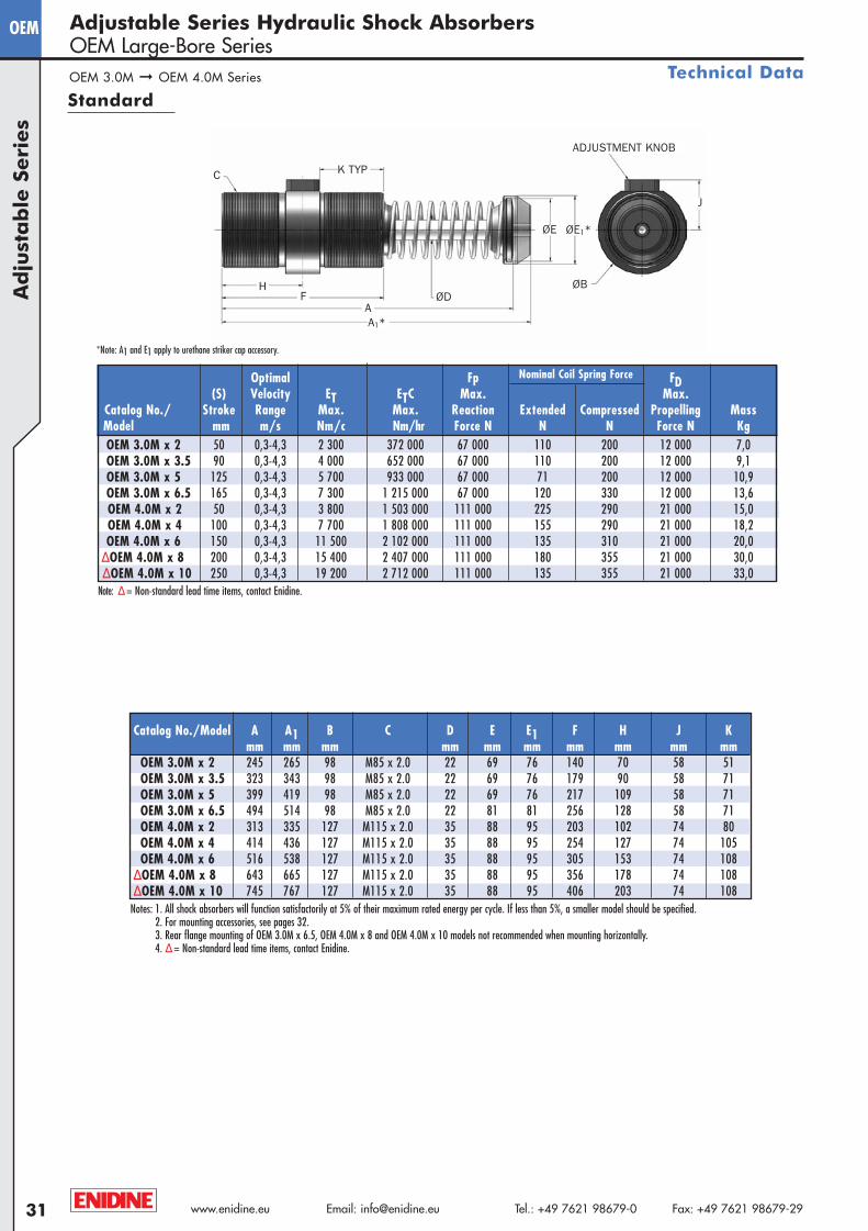
OEM 3.0M ➞ OEM 4.0M Series
Ad
just
ab
le S
eri
es
Adjustable Series Hydraulic Shock AbsorbersOEM Large-Bore Series
Technical Data
Standard
*Note: A1 and E1 apply to urethane striker cap accessory.
Catalog No./Model A A1 B C D E E1 F H J Kmm mm mm mm mm mm mm mm mm mm
OEM 3.0M x 2 245 265 98 M85 x 2.0 22 69 76 140 70 58 51OEM 3.0M x 3.5 323 343 98 M85 x 2.0 22 69 76 179 90 58 71OEM 3.0M x 5 399 419 98 M85 x 2.0 22 69 76 217 109 58 71OEM 3.0M x 6.5 494 514 98 M85 x 2.0 22 81 81 256 128 58 71OEM 4.0M x 2 313 335 127 M115 x 2.0 35 88 95 203 102 74 80OEM 4.0M x 4 414 436 127 M115 x 2.0 35 88 95 254 127 74 105OEM 4.0M x 6 516 538 127 M115 x 2.0 35 88 95 305 153 74 108
Δ OEM 4.0M x 8 643 665 127 M115 x 2.0 35 88 95 356 178 74 108Δ OEM 4.0M x 10 745 767 127 M115 x 2.0 35 88 95 406 203 74 108
Notes: 1. All shock absorbers will function satisfactorily at 5% of their maximum rated energy per cycle. If less than 5%, a smaller model should be specified.2. For mounting accessories, see pages 32.3. Rear flange mounting of OEM 3.0M x 6.5, OEM 4.0M x 8 and OEM 4.0M x 10 models not recommended when mounting horizontally.4. Δ= Non-standard lead time items, contact Enidine.
ADJUSTMENT KNOB
K TYPC
ØD
ØE ØE1*
A1*
HF
A
J
ØB
Note: Δ= Non-standard lead time items, contact Enidine.
Nominal Coil Spring ForceOptimal Fp FD(S) Velocity ET ETC Max. Max.
Catalog No./ Stroke Range Max. Max. Reaction Extended Compressed Propelling MassModel mm m/s Nm/c Nm/hr Force N N N Force N KgOEM 3.0M x 2 50 0,3-4,3 2 300 372 000 67 000 110 200 12 000 7,0OEM 3.0M x 3.5 90 0,3-4,3 4 000 652 000 67 000 110 200 12 000 9,1OEM 3.0M x 5 125 0,3-4,3 5 700 933 000 67 000 71 200 12 000 10,9OEM 3.0M x 6.5 165 0,3-4,3 7 300 1 215 000 67 000 120 330 12 000 13,6OEM 4.0M x 2 50 0,3-4,3 3 800 1 503 000 111 000 225 290 21 000 15,0OEM 4.0M x 4 100 0,3-4,3 7 700 1 808 000 111 000 155 290 21 000 18,2OEM 4.0M x 6 150 0,3-4,3 11 500 2 102 000 111 000 135 310 21 000 20,0
Δ OEM 4.0M x 8 200 0,3-4,3 15 400 2 407 000 111 000 180 355 21 000 30,0Δ OEM 4.0M x 10 250 0,3-4,3 19 200 2 712 000 111 000 135 355 21 000 33,0
A4-Metric:Project1-A4-Metric 2/13/08 8:59 AM Page 31

32www.enidine.eu Email: [email protected] Tel.: +49 7621 98679-0 Fax: +49 7621 98679-29
OEMA
dju
stab
le Se
ries
Adjustable Series Hydraulic Shock AbsorbersOEM Large-Bore Series
AccessoriesOEM 3.0M ➞ OEM 4.0M Series
Clevis Mount
Flange Foot Mount
Notes: 1. “S” indicates model is supplied with spring. 2. Δ= Non-standard lead time items, contact Enidine.
BoltCatalog No./ Part Model Ref J Y Z FA FB FC FD FE FG FJ FK Size Mass NotesModel Number mm mm mm mm mm mm mm mm mm mm mm mm kgFM M85 x 2 2F3330 OEM 3.0M 58 81,0 59,0 165,0 139,7 13,5 103,0 25,4 52,3 14,1 28,7 M12 1 984 1FM M115 x 2 2F3720 OEM 4.0M 74 190,5 37,0 203,2 165,0 16,8 149,4 38,0 79,5 16,0 50,8 M16 3 900 2
Notes: 1. OEM 3.0M x 6,5, Z dimension is 77,7mm.2. OEM 4.0M x 8 and 4.0M x 10M, Z dimension is 62,0mm.3. For rear foot mount, dimension FJ is 22,4mm.
SPRING OPTIONALLOCK RING
ØM
ØS
ØT
CR
QP
ZL
V
U
ØN
ØFC
FE
FA
FB
FG
FD
FJ
LOCK RING
Z + STROKEY + STROKE
ADJUSTMENTKNOB
(S)Catalog No./Model Stroke L M N P Q S T U V W Z CR Mass
mm mm mm mm mm mm mm mm mm mm mm mm mm kg
Δ OEM 3.0M x 2 CM (S) 50 325,0 19,07 19,07 31,7 38,0 98,0 38,1 38,1 36,0 26,0 16,0 23,0 8,66+0,25/0 +0,25/0 0/-0,3 +0.5/0
Δ OEM 3.0M x 3.5 CM (S) 90 402,0 19,07 19,07 31,7 38,0 98,0 38,1 38,1 36,0 26,0 16,0 23,0 10,70+0,25/0 +0,25/0 0/-0,3 +0.5/0
Δ OEM 3.0M x 5 CM (S) 125 479,0 19,07 19,07 31,7 38,0 98,0 38,1 38,1 36,0 26,0 16,0 23,0 12,52+0,25/0 +0,25/0 0/-0,3 +0.5/0
Δ OEM 3.0M x 6.5 CM (S) 165 574,0 19,07 19,07 31,7 38,0 98,0 38,1 38,1 36,0 26,0 16,0 23,0 15,24+0,25/0 +0,25/0 0/-0,3 +0.5/0
Δ OEM 4.0M x 2 CM (S) 50 432,0 25,42 25,42 38,1 90,5 127,0 57,2 51,0 51,0 44,0 38,2 35,0 19,23+0,25/0 +0,25/0 0/-0,3 +0.5/0
Δ OEM 4.0M x 4 CM (S) 100 533,0 25,42 25,42 38,1 90,5 127,0 57,2 51,0 51,0 44,0 38,2 35,0 22,41+0,25/0 +0,25/0 0/-0,3 +0.5/0
Δ OEM 4.0M x 6 CM (S) 150 635,0 25,42 25,42 38,1 90,5 127,0 57,2 51,0 51,0 44,0 38,2 35,0 24,22+0,25/0 +0,25/0 0/-0,3 +0.5/0
Δ OEM 4.0M x 8 CM (S) 200 762,0 25,42 25,42 38,1 90,5 127,0 57,2 51,0 51,0 44,0 38,2 35,0 34,20+0,25/0 +0,25/0 0/-0,3 +0.5/0
Δ OEM 4.0M x 10 CM (S) 250 864,0 25,42 25,42 38,1 90,5 127,0 57,2 51,0 51,0 44,0 38,2 35,0 37,37+0,25/0 +0,25/0 0/-0,3 +0.5/0
A4-Metric:Project1-A4-Metric 2/13/08 8:59 AM Page 32
www.enidine.eu Email: [email protected] Tel.: +49 7621 98679-0 Fax: +49 7621 98679-2933
OEM
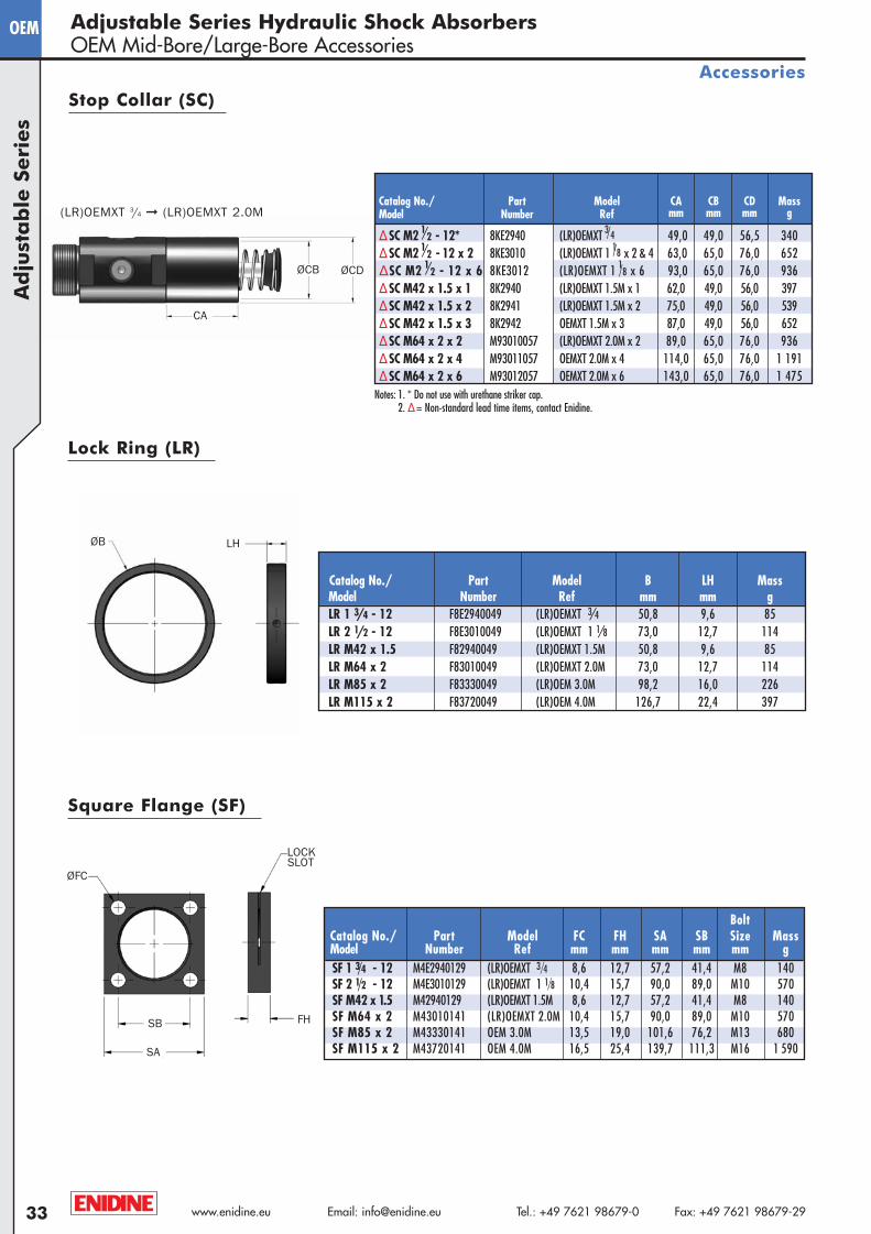
(LR)OEMXT 3/4 ➞ (LR)OEMXT 2.0M
Ad
just
ab
le S
eri
es
Adjustable Series Hydraulic Shock AbsorbersOEM Mid-Bore/Large-Bore Accessories
Accessories
Stop Collar (SC)
Notes: 1. * Do not use with urethane striker cap. 2. Δ= Non-standard lead time items, contact Enidine.
Catalog No./ Part Model B LH MassModel Number Ref mm mm gLR 1 3/4 - 12 F8E2940049 (LR)OEMXT 3/4 50,8 9,6 85LR 2 1/2 - 12 F8E3010049 (LR)OEMXT 1 1/8 73,0 12,7 114LR M42 x 1.5 F82940049 (LR)OEMXT 1.5M 50,8 9,6 85LR M64 x 2 F83010049 (LR)OEMXT 2.0M 73,0 12,7 114LR M85 x 2 F83330049 (LR)OEM 3.0M 98,2 16,0 226LR M115 x 2 F83720049 (LR)OEM 4.0M 126,7 22,4 397
Lock Ring (LR)
BoltCatalog No./ Part Model FC FH SA SB Size MassModel Number Ref mm mm mm mm mm gSF 1 3/4 - 12 M4E2940129 (LR)OEMXT 3/4 8,6 12,7 57,2 41,4 M8 140SF 2 1/2 - 12 M4E3010129 (LR)OEMXT 1 1/8 10,4 15,7 90,0 89,0 M10 570SF M42 x 1.5 M42940129 (LR)OEMXT 1.5M 8,6 12,7 57,2 41,4 M8 140SF M64 x 2 M43010141 (LR)OEMXT 2.0M 10,4 15,7 90,0 89,0 M10 570SF M85 x 2 M43330141 OEM 3.0M 13,5 19,0 101,6 76,2 M13 680SF M115 x 2 M43720141 OEM 4.0M 16,5 25,4 139,7 111,3 M16 1 590
Square Flange (SF)
CA
ØCB
ØB LH
ØFC
SB
SA
FH
LOCKSLOT
ØCD
Catalog No./ Part Model CA CB CD MassModel Number Ref mm mm mm g
ΔSC M2 1/2 - 12* 8KE2940 (LR)OEMXT 3/4 49,0 49,0 56,5 340ΔSC M2 1/2 - 12 x 2 8KE3010 (LR)OEMXT 1 1/8 x 2 & 4 63,0 65,0 76,0 652ΔSC M2 1/2 - 12 x 6 8KE3012 (LR)OEMXT 1 1/8 x 6 93,0 65,0 76,0 936ΔSC M42 x 1.5 x 1 8K2940 (LR)OEMXT 1.5M x 1 62,0 49,0 56,0 397ΔSC M42 x 1.5 x 2 8K2941 (LR)OEMXT 1.5M x 2 75,0 49,0 56,0 539ΔSC M42 x 1.5 x 3 8K2942 OEMXT 1.5M x 3 87,0 49,0 56,0 652ΔSC M64 x 2 x 2 M93010057 (LR)OEMXT 2.0M x 2 89,0 65,0 76,0 936ΔSC M64 x 2 x 4 M93011057 OEMXT 2.0M x 4 114,0 65,0 76,0 1 191ΔSC M64 x 2 x 6 M93012057 OEMXT 2.0M x 6 143,0 65,0 76,0 1 475
A4-Metric:Project1-A4-Metric 2/13/08 9:00 AM Page 33
34www.enidine.eu Email: [email protected] Tel.: +49 7621 98679-0 Fax: +49 7621 98679-29
OEMA
dju
stab
le Se
ries
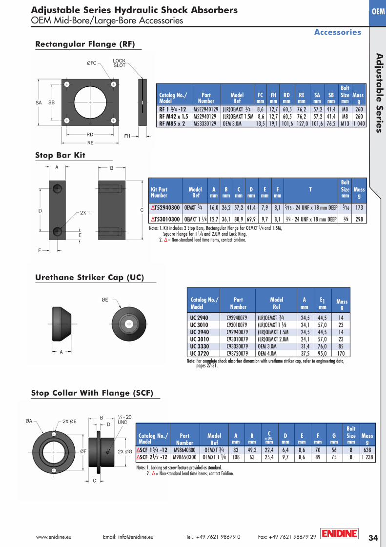
Adjustable Series Hydraulic Shock AbsorbersOEM Mid-Bore/Large-Bore Accessories
Accessories
Note: For complete shock absorber dimension with urethane striker cap, refer to engineering data,pages 27-31.
Catalog No./ Part Model A E1 MassModel Number Ref mm mm g
UC 2940 C92940079 (LR)OEMXT 3/4 24,5 44,5 14UC 3010 C93010079 (LR)OEMXT 1 1/8 24,1 57,0 23UC 2940 C92940079 (LR)OEMXT 1.5M 24,5 44,5 14UC 3010 C93010079 (LR)OEMXT 2.0M 24,1 57,0 23UC 3330 C93330079 OEM 3.0M 31,4 76,0 85UC 3720 C93720079 OEM 4.0M 37,5 95,0 170
BoltKit Part Model A B C D E F T Size MassNumber Ref mm mm mm mm mm mm mm g
ΔT52940300 OEMXT 3/4 16,0 26,2 57,2 41,4 7,9 8,1 5/16 - 24 UNF x 18 mm DEEP 5/16 173
ΔT53010300 OEMXT 1 1/8 12,7 36,1 88,9 69,9 9,7 8,1 3/8 - 24 UNF x 18 mm DEEP 3/8 298Notes: 1. Kit includes 2 Stop Bars, Rectangular Flange for OEMXT 3/4 and 1.5M,
Square Flange for 1 1/8 and 2.0M and Lock Ring.2. Δ= Non-standard lead time items, contact Enidine.
Rectangular Flange (RF)
BoltCatalog No./ Part Model FC FH RD RE SA SB Size MassModel Number Ref mm mm mm mm mm mm mm gRF 1 3/4 -12 M5E2940129 (LR)OEMXT 3/4 8,6 12,7 60,5 76,2 57,2 41,4 M8 260RF M42 x 1.5 M52940129 (LR)OEMXT 1.5M 8,6 12,7 60,5 76,2 57,2 41,4 M8 260RF M85 x 2 M53330129 OEM 3.0M 13,5 19,1 101,6 127,0 101,6 76,2 M13 1 040
Stop Bar Kit
Urethane Striker Cap (UC)
Stop Collar With Flange (SCF)
±.002
Notes: 1. Locking set screw feature provided as standard. 2. Δ= Non-standard lead time items, contact Enidine.
RD
RE
SBSA
FH
ØFC LOCK SLOT
B
CD
A
E
F
2X T
A
ØE
ØA
ØF 2X ØG
2X ØEB
D
C
1/4 - 20 UNC
BoltCatalog No./ Part Model A B C D E F G Size MassModel Number Ref mm mm mm mm mm mm mm mm g
ΔSCF 13/4 -12 M98640300 OEMXT 3/4 83 49,3 22,4 6,4 8,6 70 56 8 638ΔSCF 21/2 -12 M98650300 OEMXT 1 1/8 108 63 25,4 9,7 8,6 89 75 8 1 238
A4-Metric:Project1-A4-Metric 2/13/08 9:00 AM Page 34