LRFD design and construction of shallow foundations for highway bridge structures

Ohio Department of Transportation
John R. Kasich, Governor Jerry Wray, Director
ODOT LRFD Foundations
May 07, 2013
Alexander Dettloff, P.E. Foundation Engineer
Office of Geotechnical Engineering

2
AASHTO 6th Ed. versus 5th Ed.
Check the Plan Sheets:
AASHTO 6th Edition (2012) versus 5th Edition (2010)
3
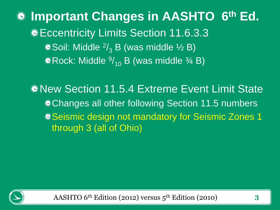
Important Changes in AASHTO 6th Ed.
Eccentricity Limits Section 11.6.3.3
Soil: Middle 2/3 B (was middle ½ B)
Rock: Middle 9/10 B (was middle ¾ B)
New Section 11.5.4 Extreme Event Limit State
Changes all other following Section 11.5 numbers
Seismic design not mandatory for Seismic Zones 1
through 3 (all of Ohio)
AASHTO 6th Edition (2012) versus 5th Edition (2010)

4
Important Changes in AASHTO 6th Ed.
Section 10.8.3.6.3 - Group Reduction Factors
for Bearing Resistance of Shafts in Sand
AASHTO 6th Edition (2012) versus 5th Edition (2010)

5
Coulomb vs. Rankine Earth Pressure
Short-heeled vs. Long-heeled Walls
Incline EH load at δ for Coulomb
Incline EH load at β for Rankine
Coulomb versus Rankine Earth Pressure

6
Coulomb Earth Pressure
Coulomb Earth Pressure

7
Broken Back Slope Analysis
Calculate B instead of β for infinite slope
For h, don't use B, use β
Broken Back Slope Analysis
Please note: In this
figure, “B” is the
“notional” or effective
slope angle.
However, in other
publications (by
FHWA), β′ or βeq are
often used.

8
Global (Overall) Stability
Global (Overall) Stability

9
Global (Overall) Stability
Resistance Factor 0.75 = Factor of Safety 1.3
Resistance Factor 0.65 = Factor of Safety 1.5
“Contains or Supports a Structural Element”
Includes:
Another wall above the lower wall
Bridge Abutment or Wing Walls
Walls with bridge foundations above or behind
(including deep foundations) where a wall failure
surface could intersect the bridge foundations
Do not cite irrelevant Factor of Safety for the
condition being analyzed
Global (Overall) Stability

10
Global (Overall) Stability
Pay attention to stability model limits
Global (Overall) Stability

11
Pile Foundations Driven to Rock
Cite Factored Load per Pile (Qp) per BDM
202.2.3.2.a
Compare Qp to maximum structural resistance
of pile, RR max = Pr = φc Pn = φc As Fy, where
φc = 0.50 for severe driving conditions
Fy = 50 ksi for H-piles
Assume pile embedment in bedrock to top of
cored bedrock per BDM 202.2.3.2.a
Include embedment in pile cap and round up
Estimated Pile Length to nearest 5 feet, per
BDM 202.2.3.2
Pile Foundations Driven to Rock

12
Driven Friction Pile Foundations
Cite Factored Load per Pile (Qp) and UBV
(Rndr) per BDM 202.2.3.2.b
Use φDYN = 0.70 to calculate UBV
Do not use Maximum UBV per pile
Compare UBV to Ultimate Capacity not to
Driving Resistance with driving strength loss
Provide justification if using a pile larger than
required by the Factored Load per Pile
Include embedment in pile cap and round up
Estimated Pile Length to nearest 5 feet, per
BDM 202.2.3.2
Driven Friction Pile Foundations

13
Driven Friction Pile Foundations
Determine minimum pipe pile wall thickness
per Construction and Material Specifications,
Section 507.06.D, UBV / 900 kip/in
Ensure Wave Equation Drivability Analyses
correspond to Static Analyses (typically
GRLWEAP versus DRIVEN)
Soil strata match in depth and strength
UBV capacity reached at same depth
UBV plot the same shape and magnitude
Use an appropriate shaft gain/loss factor per
DRIVEN user manual, Chapter 5, and GRLWEAP
manual Sections 6.1 and 6.2.
Driven Friction Pile Foundations

14
Driven Pile Foundations
When performing Drivability Analysis, per
BDM Section 202.2.3.2.b & AASHTO 10.7.8,
compare calculated driving stresses to Maximum Permissible Driving Stress, σdr
For Steel Piles, per AASHTO 10.7.8, σdr = 0.9 φda fy
Per AASHTO 6.5.4.2, φda = 1.00
Per ASTM A252, for pipe piles,
Grade 1, fy = 30 ksi (not allowed)
Grade 2, fy = 35 ksi (most common, default)
Grade 3, fy = 45 ksi (must be specified for use)
Driven Pile Foundations

15
Drilled Shaft Foundations
Self weight of drilled shaft is counteracted by
Archimedes’ principle of buoyancy:
γeffective self weight = γconcrete – γsoil
Friction drilled shaft includes side resistance
and end-bearing in soil.
Rock-socketed drilled shaft includes side
resistance and end-bearing in rock, but
neglects side resistance in soil, due to greater
amount of displacement required to engage
side resistance in soil.
Drilled Shaft Foundations

16
Drilled Shaft Foundations
Axial End-Bearing Resistance in Bedrock
AASHTO 10.8.3.5.4c-1; qp = 2.5 qu, Ncr* = 2.5.
Minimum rock socket = 1.5 B, where B = shaft
diameter (see also FHWA GEC 10, Equation 13-
20, and the associated narrative).
FHWA GEC 10, Equation 13-21 is a refinement of
the above equation for rock where spacing (sv) and
aperture (td) of discontinuities (horizontal joints) is
well known. Ncr* = 0.4 to 5.1 Requires sv ≥ 1.0 feet
and td ≤ 0.25 inch. Do not use otherwise; default to
above AASHTO 10.8.3.5.4c-1.
AASHTO 10.8.3.5.4c-1 and GEC 10, Equation 13-
20 are for “massive rock.”
Drilled Shaft Foundations

17
Drilled Shaft Foundations Per GEC 10, “Massive rock can be defined, for
purposes of bearing capacity analysis, as rock
mass for which the effects of discontinuities are
insignificant. Practically, if joint spacing is more
than four to five times the shaft diameter, or if
jointing is horizontal but the joints are tight (no
compressible or gouge-filled seams) the rock can
be treated as massive.”
Consider AASHTO Equation 10.8.3.5.4c-2 or
GEC 10 Equation 13-24 if:
Rock is highly fractured and adversely jointed
Rock contains solution cavities or voids
Open seams contain compressible material (clay)
Drilled Shaft Foundations

18
Drilled Shaft Foundations
Please Note:
AASTO Eqn. 10.8.3.5.4c-2 uses RMR, Rock Mass
Rating system.
GEC 10 Equation 13-24 uses GSI, Geologic
Strength Index.
The next edition of AASHTO will go to GSI
Drilled Shaft Foundations

19
Drilled Shaft Foundations
For Lateral Resistance using LPILE, when
foundation is Embedded in Rock, always use
LPILE Weak Rock Model, per FHWA GEC 10
12.3.3.4.4. Use of qu > 1000 psi results in a
non-critical error, which should be ignored.
LPILE Strong Rock Model is calibrated to one
certain vuggy limestone formation in southern
Florida, which crushes under load: resistance
drops to zero if deflection equals 0.24% of the
shaft diameter. This does not reflect the p-y
behavior of Ohio rocks.
Drilled Shaft Foundations

20
Wall RF Calibrated to
old Factor of Safety:
For example:
γEH =1.50 / φτ = 1.00
: FoS = 1.5
Wall Resistance Factors: AASHTO Section 10 vs. 11
Resistance Factors for Walls

21
CIP Gravity and Semi-Gravity Walls
For Sliding on Granular soils, use AASHTO Equation 10.6.3.4-2, Rτ = V tan δ.
Please note that “δ” in this equation does not equal
δ angle of interface friction in 3.11.5.3.
For Sliding on Cohesive soils, use AASHTO
Figure 10.6.3.4-1.
Note: bedding on “6.0 in. of compacted granular
material” is always assumed, and the comparison
between Su and 0.5σv is always performed.
This limits sliding resistance in stiffer clays to ½ the
contact pressure (which would be less than Su),
and limits sliding resistance in softer clays to Su,
which would be less than ½ the contact pressure.
Cast-in-Place Gravity and Semi-Gravity Walls

22
CIP Gravity and Semi-Gravity Walls
Cast-in-Place Gravity and Semi-Gravity Walls

23
CIP Gravity and Semi-Gravity Walls
For AASHTO Figure 10.6.3.4-1, read this as
“For footings that rest on clay, where footings
are supported on at least 6.0 in. of compacted
granular material, the sliding resistance may
be taken as the lesser of: The cohesion of the
clay, or one-half the normal stress on the
interface between the footing and soil, as
shown in Figure 10.6.3.4-1 for retaining
walls.”
Cast-in-Place Gravity and Semi-Gravity Walls
24
Mechanically Stabilized Earth Walls
For Sliding on Granular soils, using AASHTO
Equation 10.6.3.4-2, compare internal friction
angle, ϕr, to external friction angle, ϕf.
Since an MSE wall is composed of soil, a check of
internal sliding along the base should also be
made, and compared to external sliding along the base, i.e. δ = ϕf or ϕr. Whichever generates the
least resistance should be used for foundation
sliding resistance, per AASHTO 11.10.5.3.
Mechanically Stabilized Earth (MSE) Walls

25
Mechanically Stabilized Earth Walls
For Sliding on Cohesive soils:
Do not use the trapezoidal or triangular pressure
distribution shown in AASHTO Figure 10.6.3.4-1.
Per AASHTO C11.10.5.4, “Due to the flexibility of
MSE walls, a triangular pressure distribution at the
wall base cannot develop, even if the wall base is
founded on rock, as the reinforced soil mass has
limited ability to transmit moment. Therefore, an
equivalent uniform base pressure distribution is
appropriate for MSE walls founded on either soil or
rock.”
One-half the average vertical stress σ′v over the
entire base width B should be used.
Mechanically Stabilized Earth (MSE) Walls

26
MSE or Spread Footing Founded Walls
For Sliding and Eccentricity of Load, use Limit
State “Strength I-a” per AASHTO Figure
C11.5.6-2.
CIP Gravity, Semi-Gravity, and MSE Walls

27
MSE or Spread Footing Founded Walls
For Bearing Resistance, use Limit State
“Strength I-b” per AASHTO Figure C11.5.6-1.
CIP Gravity, Semi-Gravity, and MSE Walls

28
MSE or Spread Footing Founded Walls
Apply LS load directly for Bearing, only apply
LS load indirectly (as a component of earth
pressure) for Sliding and Eccentricity.
CIP Gravity, Semi-Gravity, and MSE Walls
29
MSE or Spread Footing Founded Walls
Because of differing Load Factors and
application of loads, “Strength I-a” bearing
pressure is always less than “Strength I-b”
bearing pressure.
Bearing is always more critical in the
“Strength I-b” limit state.
Sliding and Eccentricity are always more
critical in the “Strength I-a” limit state.
Do not perform “Strength I-a” bearing
analyses, and do not perform “Strength I-b”
sliding or limiting eccentricity analyses.
CIP Gravity, Semi-Gravity, and MSE Walls

30
MSE or Spread Footing Founded Walls
For bearing analyses on soil, always use
effective base width B′ = B – 2e, and uniform
bearing pressure per AASHTO Sections
10.6.1.3 and 11.6.3.2.
For this case, calculate eccentricity (e) with
“Strength I-b” limit state loading.
For bearing analyses on rock, use a linearly
distributed pressure over the entire base
width B.
For MSE Walls on rock, use the average
pressure over the entire base width B.
CIP Gravity, Semi-Gravity, and MSE Walls

31
Cantilever Non-Gravity Walls
For Minimum Embedment, use maximum of:
1. Minimum Embedment depth to resist Factored
(Strength I) Axial Loads; however, this is typically
neglected for non-anchored walls.
2. Minimum Embedment depth to meet Service-
ability deflection limit at head of wall (under
Service I limit state loading), typically:
1% of exposed height, if adjacent and above roadway
2 inches, if adjacent and below existing roadway
1% of length above bedrock otherwise
3. Minimum Embedment Depth for moment
equilibrium about toe (point F), per AASHTO
Figure 3.11.5.6-1 through Figure 3.11.5.6-3
Cantilever Non-Gravity Walls

32
Cantilever Non-Gravity Walls
Cantilever Non-Gravity Walls

33
Cantilever Non-Gravity Walls For AASHTO Figure 3.11.5.6-1 through Figure
3.11.5.6-3,
b = width of vertical member
S = spacing of vertical members
Use b where S > 3b
Use S where S ≤ 3b
Use Strength I factored load and factored resistance
γEH = 1.50 per AASHTO Table 3.4.1-2
γLS = 1.75 per AASHTO Table 3.4.1-2
φp = 0.75 per AASHTO Table 11.5.7-1
See AASHTO C11.8.4.1 for an example of how to use
the load and resistance factors with Figure 3.11.5.6-3.
Similar principles can be used with Figure 3.11.5.6-1 and
Figure 3.11.5.6-2.
Cantilever Non-Gravity Walls

34
Cantilever Non-Gravity Wall
For Structural Design, calculate Maximum
Moment and Shear in vertical members, both
within exposed height (cantilever section) and
in vertical member as a whole.
Consider exposed height as unbraced member
Unbraced Length (Lb per AASHTO 6.10.8.2.3) =
Exposed Height
Consider embedded length as continuously braced
member
Cantilever Non-Gravity Walls

35
Anchored Walls
Use Apparent Earth Pressure (AEP) model
per AASHTO Section Section 3.11.5.7
Use Load Factor γEH = 1.35 for AEP per
AASHTO Table 3.4.1-2
For Minimum Embedment, use maximum of:
1. Minimum Embedment depth to resist Axial
Loads, including anchor loads and self weight
2. Minimum Embedment depth per FHWA GEC 4,
Section 5.5 for passive lateral resistance.
3. Minimum Embedment Depth for moment
equilibrium about toe
Anchored Walls
36
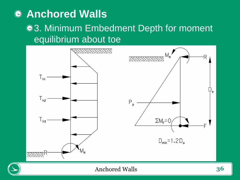
Anchored Walls
3. Minimum Embedment Depth for moment
equilibrium about toe
Anchored Walls

37
Anchored Walls
3. Determine Minimum Embedment Depth for
moment equilibrium about toe, where:
b = width of vertical member
S = spacing of vertical members
Pp = 3/2 φp kp γ′ b D2, where S > 3b
Pp = ½ φp kp γ′ S D2, where S ≤ 3b
φp = 0.75 per AASHTO Table 11.5.7-1
ΣMF = MR + DO R + Do/3 Pp = 0
Dmin = 1.2 DO
These are Strength I Factored Loads
Soil Nail Walls are not Anchored Walls:
design soil nail walls per FHWA GEC 7
Anchored Walls

38
Thank You
Questions?
ODOT LRFD Foundations