
ODOT InRoads V8i SS4 User Guide - Home · PDF fileMicroStation InRoads V8i SS2 Instruction...
61
Transcript of ODOT InRoads V8i SS4 User Guide - Home · PDF fileMicroStation InRoads V8i SS2 Instruction...


Page | 2 Oregon Department of Transportation May 2018 Engineering Applications Support Team
US-20 ROUNDABOUT AT W BARCLAY DR., SISTERS, OREGON
COVER PHOTO AND DESIGN BY ODOT PHOTO/VIDEO
MAY 2018

May 2018 Oregon Department of Transportation Page | 3 Engineering Applications Support Team
Table of Contents HOW TO USE THIS GUIDE ................................................................................................................ 7
Assumptions and Layout ......................................................................................................................... 7
Assumptions 7
Layout 7
Acknowledgement 7
Text and Format Conventions................................................................................................................. 7
Fonts and Formats 7
Blue boxes 8
Naming copied files 8
ABOUT INROADS V8I (SELECTSERIES 4) ............................................................................................ 9
OpenRoads Technology .......................................................................................................................... 9
Legacy Tools and Workflows .................................................................................................................. 9
Concurrent Use of SS2 and SS4 ............................................................................................................... 9
Civil Tools Workflows versus InRoads Explorer .................................................................................... 10
Civil Tools 10
Legacy Tools and “Native” Data Types 11
Other Notable Changes ........................................................................................................................ 11
Known Issues with SS4 .......................................................................................................................... 11
Slower Launch and Exit 11
Slower Model Changes 11
Input While Command Active Can Cause a Crash 12
WORKING WITH CIVIL GEOMETRY ................................................................................................. 13
Feature Definitions with Civil Geometry .............................................................................................. 13
Annotation for Plans 13
Auto Annotation ................................................................................................................................... 14
Auto Export ........................................................................................................................................... 14
Civil Geometry Annotation Known Issues ............................................................................................ 15
Auto Annotation Stationing Disappears 15
Missing Major Station after Equation 15
Legacy Geometry Known Issues ........................................................................................................... 16
Cannot Load a Read-Only .alg file 16
WORKING WITH SURFACES: TERRAIN MODELS AND DTMS ............................................................ 18

Page | 4 Oregon Department of Transportation May 2018 Engineering Applications Support Team
Terrain Models ...................................................................................................................................... 18
Terrain Model Features 18
Terrain Models from .dtm files 19
Graphical Filters 20
WORKING WITH TEMPLATES ......................................................................................................... 21
Location ................................................................................................................................................ 21
What’s in ODOTSS4_seed.itl? ............................................................................................................... 21
Structure of ODOTSS4_seed.itl 22
What’s Different in ODOTseed_SS4.itl? ................................................................................................ 23
Superelevation Flags 23
Rollover Locks 23
Feature Definitions for Material Layers 24
Create Template Dialog Opens Empty 24
WORKING WITH CORRIDORS ......................................................................................................... 26
Creating Corridors ................................................................................................................................. 26
How to Change Design Stage ................................................................................................................ 26
WORKING WITH SUPERELEVATION AND POINT CONTROLS ............................................................ 28
Known Superelevation Issues in SS4 28
WORKING WITH CROSS SECTIONS, VOLUMES AND PROFILES ......................................................... 30
OpenRoads vs. Legacy........................................................................................................................... 30
Cross Sections - Dynamic and Permanent ............................................................................................ 30
Known Issues ........................................................................................................................................ 31
Big Plus Signs in Cross Sections 31
Corridor Components are not displayed in Dynamic Cross Sections 31
Known Issues with Dynamic Cross Sections and Profile Model 31
Create Cross Sections 32
Annotate Cross Sections ....................................................................................................................... 33
WORKING WITH REPORTS ............................................................................................................. 35
Creating Reports ................................................................................................................................... 35
Known Issue with Reports in InRoads SS4 ............................................................................................ 35
Final Cumulative Earthwork Volumes not Totaled 35
WORKING WITH DRAINAGE .......................................................................................................... 36
InRoads V8i SS4 Legacy Versus SS2 ...................................................................................................... 36
Drainage in SS4 36

May 2018 Oregon Department of Transportation Page | 5 Engineering Applications Support Team
Storm and Sanitary Drainage in SS2 36
Drainage Network Display in Plan View ................................................................................................ 36
WORKING WITH SURVEY ............................................................................................................... 37
APPENDIX A: LAUNCHING INROADS .............................................................................................. 38
InRoads Shortcuts ................................................................................................................................. 38
Concurrent Use of SS2 and SS4 ............................................................................................................. 38
Launching InRoads SS4 ......................................................................................................................... 38
Initial Launch Interface ......................................................................................................................... 38
Working Offline ..................................................................................................................................... 39
Before Working Offline 39
APPENDIX B: INROADS V8I SS4 FILES IN F:\ODOT_DATA\USERCFG\INROADS\SS4 .......................... 41
Shortcut 41
Preference File (.xin) 43
Template Library Seed File (.itl) 43
APPENDIX C: PREFERENCE FILES (.XIN) ........................................................................................... 44
Preference Files .................................................................................................................................... 44
CivilSS4.xin 44
Can I Customize My XIN file? 44
Preference Sets 45
ODOT Preference Set 45
ODOT-Plans preference set 46
Determining Command Dialog Preference Settings 46
How Preferences Are Named 47
Styles and Named Symbologies 48
APPENDIX D: SETTINGS AND PREFERENCES .................................................................................... 50
Settings in Seed Design Files ................................................................................................................. 50
Model Names 50
Design File Settings 50
InRoads V8i SS4 Default Preferences .................................................................................................... 52
Changing Your Preferences 52
APPENDIX E: CIVIL STANDARDS ..................................................................................................... 54
Civil Cells ............................................................................................................................................... 54
Design Standards .................................................................................................................................. 55
Using the Design Standards Toolbar 55

Page | 6 Oregon Department of Transportation May 2018 Engineering Applications Support Team
Feature Definitions and Element Templates ........................................................................................ 56
About Feature Definitions 56
About Element Templates 57
Project Settings –Design Stages ............................................................................................................ 59
Terrain Filters and Filter Groups ........................................................................................................... 60
APPENDIX F: VARIABLES (REGISTRY) .............................................................................................. 61

May 2018 Oregon Department of Transportation Page | 7 Engineering Applications Support Team
How to Use This Guide
Assumptions and Layout
Assumptions
This guide focuses on ODOT configuration and customization of the Bentley InRoads V8i
SELECTSeries4 (SS4) product. It is intended as a reference for InRoads users migrating to InRoads V8i
SS4 from InRoads V8i SS2.
This guide assumes previous training on, and a working knowledge of:
ProjectWise
MicroStation
InRoads V8i SS2
Instruction for basic use of these applications is presented in training and other instructional
material from Bentley and third-party training vendors.
Layout
This guide indicates when procedures in SS4 use tools in the MicroStation Tasks>Civil Tools groups
and when they follow legacy workflows using InRoads Explorer menus. Workflows for typical ODOT
procedures using InRoads V8i SS4 are provided on the EAST website.
Acknowledgement
Many of the images in this guide were produced from project data that was provided for training by
CAD Productivity Incorporated from Nashville, Tennessee. The dataset provides consistency in the
images with the application of ODOT standards as you step through workflows. Thanks go out to
Sam Nugent and Todd Stutts for their work in applying ODOT standards to the project data.
Text and Format Conventions In this guide, certain conventions are used.
Fonts and Formats
Franklin Gothic Medium Cond font indicates an InRoads Explorer file menu option.
Example: “Use the InRoads command Geometry>View Geometry>Stationing…”
Bold Calibri font indicates:
The name of a screen element, such as a dialog box, tool, checkbox or field. Examples:
Example: “The Print Organizer icon” Example: “The Pattern Area dialog”
A menu option that you select from top-line menus other than that of InRoads Explorer (e.g., MicroStation, Windows, Print Organizer, etc.)
MicroStation top menu items are in Bold Calibri font and preceded with “MS:”

Page | 8 Oregon Department of Transportation May 2018 Engineering Applications Support Team
“MS: Tools>Cells>Place Active Cell”
Bold italicized Calibri font indicates a selection you make in a field.
Example: “In the Pattern Definition field select From Cell.”
Courier New bold, 10 pt. indicates a file name, a path to a folder or file, and commands
that you key in (enter on a command line) as text.
Example: “The legacy geometry style definitions are in the civilSS4.xin file” Example: “A new template library seed file is named ODOTSS4_seed.itl and is stored in the F:\ODOT_DATA\USERCFG\InRoads\SS4 folder.”
Arial 11-pt. font is used for names of preference, feature definitions, and styles.
Example: “ODOT-Plans uses a style named CL_Main.” Example: “CL_Scratch is the only feature definition with both settings set to False…”
The “greater than” (“>”) angled bracket indicates sub menu and sub-sub menu selections,
and sub-folder and sub-sub folder selections.
Example: “Annotate Cross Sections is under Civil Tools >Corridor Modeling”
Blue boxes
Additional information is provided in shaded one-row tables with icons indicating the type
information.
Note: Notes contain additional information about a topic to help you understand how it works, why it is configured as it is, or how to use it.
Tip! Tips describe non-essential information about actions that may help you to use the application more efficiently.
Reminder: Reminders re-state information that is presented elsewhere in the guide that is also of relevance in the current section. An example would be: a reiteration of what characters may be used for file names, under a section on saving files.
Caution! Cautions alert you to actions or non-actions that might result in loss of data (overwriting files), corruption of files or a substantial loss of time. An example would be failing to run the Offline_Workspace before departing for the field, and being unable to run MicroStation until you reconnect to the network.
Naming copied files
Where copied or customized file or folder names are recommended; please use the following
substitutions:
keynu = project key number (5 digit numeric value) myname = your name (first or last or both)
------------------------------------------

May 2018 Oregon Department of Transportation Page | 9 Engineering Applications Support Team
About InRoads V8i (SELECTseries 4)
OpenRoads Technology
Figure 1. The Bentley InRoads SS4 splash screen
Starting with the InRoads V8i SS3 release, and continuing with SS4, Bentley began incorporating
what they call OpenRoads technology, to integrate more functionality of InRoads into the
MicroStation interface, moving the commands from the InRoads Explorer menus to the MS Tasks
dialog under Civil Tools. This produces significant differences in some SS4 workflows from SS2
workflows, and some new features are available in SS4 that did not exist in the InRoads V8i SS2
version.
Legacy Tools and Workflows
In this manual, the term legacy refers to tools and workflows in SS4 that still use the InRoads
Explorer menus (File, Surface, Geometry, Drainage, Evaluation, Drafting, Quantities, Tools). Legacy
procedures will be much the same in SS4 as in SS2, with minor changes that are called out.
In a few cases, ODOT has not yet developed workflows that use InRoads V8i SS4 to perform tasks
that align with ODOT conventions; in these cases we note that the work should be performed using
the SS2 version of the software.
Concurrent Use of SS2 and SS4
Do not run InRoads SS4 and SS2 at the same time. This includes not running InRoads SS2 Lite at the
same time as InRoads SS4. Specifically, do not launch InRoads SS2 Lite from the MicroStation ODOT
menu when you have InRoads SS4 open, even though the link to open it may be there.

Page | 10 Oregon Department of Transportation May 2018 Engineering Applications Support Team
Civil Tools Workflows versus InRoads Explorer In InRoads V8i SS4, you use workflows and commands under MicroStation Tasks>Civil Tools to
perform many of the functions that were previously initiated using InRoads Explorer.
Figure 2. Workflows under Tasks> Civil Tools
used for InRoads SS4 functionality
Civil Tools
Workflows for which you now use MicroStation Tasks>Civil Tools include:
General Geometry (formerly under Geometry)
Horizontal Geometry (formerly under Geometry)
Vertical Geometry (formerly under Geometry)
Terrain Models (alternatives to Surface .dtm files)
Corridor Modeling: o Create Corridor (formerly under Modeler>Roadway Designer) o Create Cross Sections (formerly under Evaluation>Cross Section) o Annotate Cross Sections (formerly under Evaluation>Cross Section) o End Area Volumes (formerly under Evaluation>Volumes)
Civil Cells
Survey replaces “Survey” Add-In

May 2018 Oregon Department of Transportation Page | 11 Engineering Applications Support Team
Note that there is no replacement for the Storm and Sanitary Add-In in SS4. For that functionality
you must use InRoads V8i SS2. A different Bentley product runs in SS4 named Subsurface Utility
Engineering, which includes Subsurface Utility Design and Analysis. SUE/SUDA will be implemented
at a later date and information about SUE/SUDA is not included in this user guide.
Legacy Tools and “Native” Data Types
Some workflows still require InRoads Explorer commands, used in the same manner as in SS2. The
ODOT configuration of InRoads V8i SS4 is set to open the InRoads Explorer window upon launching
the application. In this manual and elsewhere, you will see the term legacy used to refer to design
approaches that still rely on the InRoads Explorer interface. Some of these are listed below.
Create and Annotate Profiles
Drainage Annotation
Display of Horizontal and Vertical Alignments
Vertical Alignment Annotation
The term “native” refers to data types, such as styles, used by legacy tools. These data types are
stored in standalone files (e.g., .dtm, .alg, .xin), rather than being included in the .dgn.
Other Notable Changes Feature Definitions
Greater use of Element Templates
Civil Standards provided through design libraries (.dgnlib)
Civil Message Center – logging actions and messages similar to MS Message center
Separate .xin and .itl files (in separate locations) for SS2 And SS4 (to take advantage of new functionality and operation in SS4)
Known Issues with SS4
Slower Launch and Exit
InRoads V8i SS4 is slower to launch and exit than InRoads V8i SS2. Part of the reason for the
slowness is that the Civil Model must be scanned to display the civil data. Another reason is the SS4
interface must always consider which tasks to display based upon the dimensionality of the active
model in the .dgn (2D or 3D). In the course of designing a roadway, you will change the active
model from 2D to 3D, and back again - many times.
Slower Model Changes
Each time the model dimensionality changes, the interface must reload. Also, each time you change
models, the civil data has to be gathered from the active model and its references. Changing models
takes time.

Page | 12 Oregon Department of Transportation May 2018 Engineering Applications Support Team
Input While Command Active Can Cause a Crash
If you provide input (click the mouse) before InRoads is ready, you will cause a crash. Some of the
InRoads V8i SS4 commands do not display a progress bar, so it is difficult to determine when a
command has finished and InRoads is ready.
What Does a Crash Look Like?
Three signs of a crash:
The application may freeze and display “(Not Responding)” in the title bar
The mouse cursor may turn into the spinning refresh wheel and stay that way for more than 20 seconds
(After a while) Microsoft, MicroStation or InRoads produces a Problem Notification dialog.
If you experience any of these signs, look around the interface - if you have a progress bar in the
lower right corner, InRoads may just be busy executing your command.
How to Avoid a Crash
If you have just executed a command or changed the active model, and you are not sure if InRoads
is ready for more input - move the mouse cursor over the buttons on the task menu. If the buttons
highlight yellow and you see tool tips, InRoads is ready for you to click the mouse.
How to Recover From a Crash
Locate the InRoads icon on the taskbar, right-click on it and choose "Close window". You should
then be able to relaunch InRoads. Although it also works to cancel the operation of InRoads through
Problem Notification dialogs, this method can take a lot of time.
----------------------------------------------

May 2018 Oregon Department of Transportation Page | 13 Engineering Applications Support Team
Working with Civil Geometry
Feature Definitions with Civil Geometry
The behavior and appearance of civil geometry are controlled by the feature definition assigned to
it. Feature definitions for linear geometry use the same native styles for alignments that are used
with SS2, so their appearance has not changed. But there are two new properties that control:
Automatic stationing
Creating and updating in the native format (.alg).
The table below shows the automatic settings of some of the feature definitions for linear geometry.
Table 1. Automatic Settings for Linear Geometry Feature Definitions
Name Auto Annotate Auto Export Use for
CL_Scratch False False All geometry elements prior to complexing
ODOT True True Complexed working and final geometry
CL_Main True True Complexed working and final geometry
CL_Minor True True Complexed working and final geometry
CL_Ramp True True Complexed working and final geometry
CL_Scratch is the only feature definition with both settings set to False and though most CL_
feature definitions auto annotate, they do so with the ODOT native style. When you are sketching
in lines, use CL_Scratch. When you need to see automatic stationing, you can use the command
Civil Tools>General Geometry>Set Feature Definition to assign the ODOT feature definition.
Figure 3. The General Geometry group of tools under Tasks> Civil Tools
An alignment can retain the ODOT feature definition and not ever be changed to a CL_ feature
definition.
Annotation for Plans
Annotations for plans do not use automatic stationing of the civil geometry. Annotation for plans is
covered in the SS4 workflow Annotating Horizontal Alignments for Plans.

Page | 14 Oregon Department of Transportation May 2018 Engineering Applications Support Team
Auto Annotation
Auto annotation is useful for designers. When you are working with civil geometry, it is often nice to
be able to see the stationing and have it update dynamically as you make changes. The auto
annotation is ruled to the geometry, so it is not permanent and is not really within your control.
When geometry is auto annotated prior to being complexed and is then modified by adding curves
and spirals, the trimmed tangents retain the auto annotation, even though you no longer see the
tangent piece. It is for this reason that the CL_Scratch feature definition was created. Use
CL_Scratch as the feature definition while you are building your alignment. Once the alignment
has been complexed, you may assign the ODOT or other CL_ feature definition.
Figure 4. Element Information dialogs comparing linear geometry properties of
CL_Main (left) and CL_Scratch (right)
Auto Export
By default in the ODOT workspace, civil geometry alignments do not Auto Export (even though Auto
Export is set to True in the Feature Definitions for Linear Geometry). ODOT’s preferred method is to
manually export at the time an .alg or annotation for plans is required.
To manually export a civil geometry alignment, use the command Export to Native from the Civil
Tools>General Geometry tasks.
Figure 5. The Terrain Model group of tools under Tasks> Civil Tools

May 2018 Oregon Department of Transportation Page | 15 Engineering Applications Support Team
To Auto Export and have the changes to civil geometry alignment update the .alg, open MS:
Settings>Design File>Civil Formatting and set the value of the Export to Native field to Use Feature
Setting.
Figure 6. Design File Settings in ODOT seed .dgn file.
Export to Native is set to Manual
Civil Geometry Annotation Known Issues
Auto Annotation Stationing Disappears
When using the ODOT feature definition, which is set to auto annotate stationing, you may notice
that the stationing has vanished. This is a temporary display issue; the graphics are still in the file. If
you fit the view, you may see the stationing displayed miles away to the upper right. To fix this
display problem, exit InRoads and re-open the .dgn file containing the geometry. You may need to
slightly adjust the geometry using the manipulators to force the auto annotation to update.
Missing Major Station after Equation
When viewing auto annotation or legacy stationing, the major station and its tick following a station
equation are not displayed. This is a defect. Ignore the behavior in auto annotation and use manual
methods to place the tick and the station text when performing legacy annotation for plans.

Page | 16 Oregon Department of Transportation May 2018 Engineering Applications Support Team
Figure 7. Missing major station text and tick for "J" 125
--------------------------------------
Legacy Geometry Known Issues
Cannot Load a Read-Only .alg file
Upon attempting to open a geometry project file (.alg), you may get an “Error writing to file”
message and the project doesn’t load.
This can happen if:
The file attribute is set to Read-Only
If you are attempting to load a geometry project file from another person’s F:\ODOT_DATA\Projects folder structure.

May 2018 Oregon Department of Transportation Page | 17 Engineering Applications Support Team
Figure 8. Error messages when loading Read-only files. The status bar reports the error, and
it is also logged in the Civil Message Center
To avoid this, ensure that the geometry project is in a location where you have write access and that
the file is not set to Read-Only. This may entail copying the .alg file from someone else’s
F:\ODOT_DATA\Projects folder and saving it in your own.
--------------------------------------------

Page | 18 Oregon Department of Transportation May 2018 Engineering Applications Support Team
Working with Surfaces: Terrain Models and DTMs
Terrain Models
Terrain Models (“Terrains”) are a new element type in MicroStation. They are similar to legacy
InRoads Surfaces (digital terrain models - .dtm files); however, terrain models are stored in .dgn
files, not as .dtm files. They can be attached as references.
Terrains are three dimensional, so if you create one in 2D, MicroStation automatically creates a 3D
model and attaches it as a reference.
Commands for creating and editing Terrain Models are in the Civil Tools>Terrain Model tasks.
Figure 9. The Terrain Model group of tools under Tasks> Civil Tools
Note: Terrain Models are elements, and should not be confused with MicroStation models. Likewise, do not confuse them with digital terrain model files.
Terrain Model Features
Terrain Models are made up of named sets of points known as features. A feature can be of various types, corresponding to the type of points it contains:
Spot or Spot Elevation
Breakline or Soft Breakline
Boundary (external)
Drape Boundary
Contour
Hole
May 2018 Oregon Department of Transportation Page | 19 Engineering Applications Support Team
Void
Drape Void
Break Void
Island
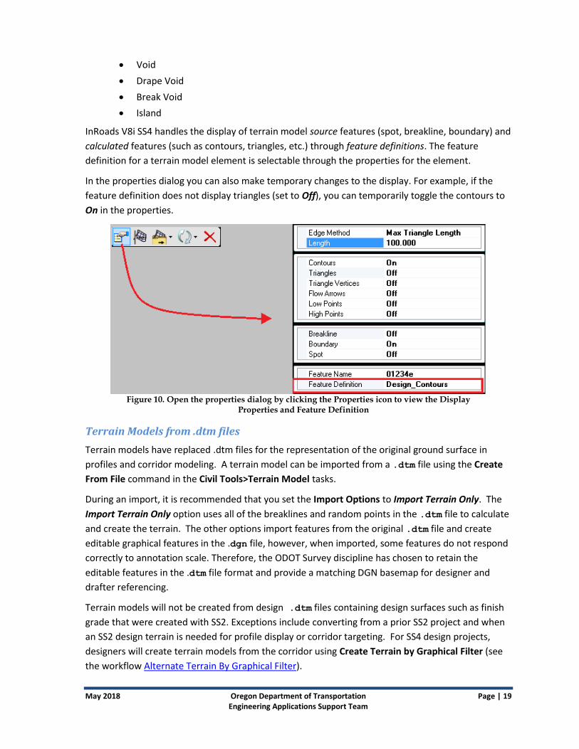
InRoads V8i SS4 handles the display of terrain model source features (spot, breakline, boundary) and
calculated features (such as contours, triangles, etc.) through feature definitions. The feature
definition for a terrain model element is selectable through the properties for the element.
In the properties dialog you can also make temporary changes to the display. For example, if the
feature definition does not display triangles (set to Off), you can temporarily toggle the contours to
On in the properties.
Figure 10. Open the properties dialog by clicking the Properties icon to view the Display
Properties and Feature Definition
Terrain Models from .dtm files
Terrain models have replaced .dtm files for the representation of the original ground surface in
profiles and corridor modeling. A terrain model can be imported from a .dtm file using the Create
From File command in the Civil Tools>Terrain Model tasks.
During an import, it is recommended that you set the Import Options to Import Terrain Only. The
Import Terrain Only option uses all of the breaklines and random points in the .dtm file to calculate
and create the terrain. The other options import features from the original .dtm file and create
editable graphical features in the .dgn file, however, when imported, some features do not respond
correctly to annotation scale. Therefore, the ODOT Survey discipline has chosen to retain the
editable features in the .dtm file format and provide a matching DGN basemap for designer and
drafter referencing.
Terrain models will not be created from design .dtm files containing design surfaces such as finish
grade that were created with SS2. Exceptions include converting from a prior SS2 project and when
an SS2 design terrain is needed for profile display or corridor targeting. For SS4 design projects,
designers will create terrain models from the corridor using Create Terrain by Graphical Filter (see
the workflow Alternate Terrain By Graphical Filter).

Page | 20 Oregon Department of Transportation May 2018 Engineering Applications Support Team
Graphical Filters
At times it may be necessary to create a terrain from specific features in a corridor. For this, use the
command Create Terrain Model by Graphical Filter in Civil Tools>Terrain Model tasks. Two design
Graphical Filter groups are provided: Road Finish Terrain and Road Subgrade Terrain.
The filter groups are made up of filters that create selections based upon the feature definition
assigned to the feature in the terrain. Road Finish Terrain uses two filters to select all of the
features at finish grade elevation: interior and limits of construction. Road Subgrade Terrain uses
three filters: subgrade beneath the impervious surface of the roadway, side slopes, and the limits of
construction.
Figure 11. 3D view showing the selection (cyan) of features of a subgrade terrain while creating
terrain by Graphical Filter using the Road Subgrade Terrain Graphical Filter Group.
Known Issues with Graphical Filters
Graphical filters cannot be used to select feature definitions from a civil cell. In addition, graphical
filter selection sometimes misses features in a corridor. When creating a terrain model from a
corridor using graphical filters, carefully check the features in your resulting terrain. Missed features
may be appended to the terrain using the command Add Features in Civil Tools>Terrain Model
tasks.
Figure 12. Add Features in the Terrain Model group of tools under Tasks> Civil Tools
----------------------------

May 2018 Oregon Department of Transportation Page | 21 Engineering Applications Support Team
Working with Templates InRoads V8i SS4 provides a few enhancements to the templates used with InRoads V8i SS2. ODOT
has delivered a separate template library seed file specifically configured to be used with SS4. The
most notable enhancement is the Superelevation flag. The Superelevation flag has been set on all
appropriate points in the ODOT components and sample templates so that you may apply
superelevation when you perform corridor modeling.
Location
The new ODOT InRoads V8i SS4 template library seed file is named ODOTSS4_seed.itl and is
stored in the F:\ODOT_DATA\USERCFG\InRoads\SS4 folder.
We recommend that you copy ODOTSS4_seed.itl into your project directory in the Windows file system or import it into a ProjectWise project folder structure and rename it according to ODOT naming conventions.
You can use the Engineering folder shortcut on the desktop of your workstation to access the
ODOTSS4_seed.itl file.
1. Open the Engineering folder (go to the desktop and double-click on the shortcut).
2. Double-click on the ODOT_User_Configuration shortcut to open a Windows Explorer dialog.
3. Open the InRoads folder.
4. Open the SS4 folder.
The ODOTSS4_seed.itl file is in the SS4 folder.
What’s in ODOTSS4_seed.itl? ODOT’s SS4 template library seed file contains:
A Point Name List of point names to be assigned to points in your templates
Folders of three categories of components:
o Roadbed Components
o End Condition Components
o Advanced Components
Several “Sample Templates”
An empty “Templates” folder for you to use.
Each component in ODOTSS4_seed.itl has been assigned a
feature definition whose name begins with MAT-. Only MAT-
feature definitions allow components to be displayed in cross
sections and to have their quantities accumulated in end-area
volume reports.

Page | 22 Oregon Department of Transportation May 2018 Engineering Applications Support Team
Structure of ODOTSS4_seed.itl
Folders
Folders in ODOTSS4_seed.itl separate roadbed components from end conditions and more
advanced components. The Roadbed and Advanced Components folders include sub-folders
containing components for assembling templates. Roadbed component sub-folders are further
divided by material/type.
Component names
Component names within each folder begin with either a sub-type or a material, for sorting
purposes. Descriptions have been added to most components to further describe their use or a
setting. To read a component description, double-click on that component in the Template Library
window to make it the Current Template.
Figure 13. Create Template dialog showing Sidewalk, Curb & Gutter,
Standard template loaded with its description displayed
Point names
Points within components are named beginning with the location, followed by the material layer on
which the point resides. Examples of point names are TL, CurbTF, CL-SG, and EP-LV.
Each point name is associated to a feature definition which controls the display of the feature
created when modeling a corridor. When naming points, it is a best practice to select a name from

May 2018 Oregon Department of Transportation Page | 23 Engineering Applications Support Team
the Point Name List, which assigns the correct feature definition to the point. The feature definition
is retained when you edit the point name.
More information about using the components to create templates can be found in the ODOT
InRoads V8i SS2 User Guide.
What’s Different in ODOTseed_SS4.itl?
The following changes to the points and components in the SS4 template library allow more
functionality when assigning superelevation to a corridor and when creating terrain models using
graphical filters.
Superelevation flags
Rollover locks
RDWY-Subgrade, -Base, and -Rock feature definitions assigned to points below finish
grade
There are also a few additional styles for points that are only found in SS4.
Superelevation Flags
In SS4, superelevation flags are set on component template points at the finish grade from the
center line out to the travel lane.
Rollover Locks
You will need to set locks on Rollover Values for points in your assembled templates that are at the
finish grade, but outside the edge of the traveled way. Points that are required to maintain the same
superelevation as the travel lane are points such as: EP, Erk, GrF, and BarBF.
To see the correct settings of rollover locks, open the Point Properties dialog for the points in the
sample template, 2 Lane with Guardrail as illustrated below.
1. In the Create Template dialog, open the Sample Template, 2 Lane with Guardrail.
2. Zoom in on the sample image.
3. Right-click on a point of the type for which you want to see the rollover lock settings and
select Edit Point….
4. In the Point Properties dialog, you can see where the lock for Rollover Values is set by
looking for a check mark to the left of the [Rollover Values] button under any Constraint of
type Slope.

Page | 24 Oregon Department of Transportation May 2018 Engineering Applications Support Team
Figure 14. Image showing the lock selected for Rollover Values
in the Point Properties dialog for a GrF_R point
Feature Definitions for Material Layers
InRoads V8i SS4 does not use feature filters, so there is no easy way to select all of the features
created on one material layer, as you might for an alternate surface. New styles have been created
that correspond to the material layers. The new styles are paired with feature definitions of the
same name, which allows the selection of all of the features on one material layer. The new feature
definitions are applied in the components and sample templates in ODOTSS4_seed.itl.
RDWY-Subgrade is the feature definition assigned to all points at the subgrade layer, which lies along the bottom of the aggregate base
RDWY-Rock is assigned to points at the top of rock
RDWY-Base is assigned to points at the top of the base course
Create Template Dialog Opens Empty
The Create Template dialog (opened from Tasks>Civil Tools>Corridor Modeling ) is configured
to open the first time without a template library (.itl) loaded. This is to encourage you to open the
ODOTSS4_seed.itl and save it (with a new name) to your project folder the first time you need
the template library. The ODOTSS4_seed.itl file is in USERCFG\InRoads\SS4.
The Create Template dialog is set to look in your working directory for the .itl in the Project
Defaults, so subsequent opening does not require any navigation.

May 2018 Oregon Department of Transportation Page | 25 Engineering Applications Support Team
Figure 15. Create Template dialog
--------------------------------------

Page | 26 Oregon Department of Transportation May 2018 Engineering Applications Support Team
Working with Corridors
Creating Corridors
The prerequisite for creating a corridor is to have a civil geometry horizontal alignment with a
vertical profile, either loaded or referenced.
When you create a corridor, a 3D model is automatically created and attached to the 2D model. In
addition, the 3D versions of 2D models which are attached to the 2D model are attached to the 3D
model.
How to Change Design Stage
Corridor design stages are numbered to indicate increased complexity as the numbers increase. The
design stage name indicates a typical design phase that is associated with the complexity.
Figure 16. Design Stage Options
Set the Design Stage for your corridor based upon the amount of detail you need or what the output
of the model needs to be (see Table below). Lower-numbered Design Stages (0-2) show less detail
and process faster. If you need more detail, select one of the higher numbered Design Stages.
1. Left-click on the corridor (tip: click on a handle, or confirm from the pop up upon clicking
that you have selected a corridor).
2. From the context-sensitive commands, select Properties (the left-most icon).
3. In the properties table that opens, use the dropdown to select a Design Stage.
4. After making the selection, WAIT until the properties box goes away. It can take a while for
the model to update, and making another selection while it is processing might cause the
application to crash (see Input While Command Active Can Cause a Crash).

May 2018 Oregon Department of Transportation Page | 27 Engineering Applications Support Team
Table 2. Design Stage Settings
Design Stage >> 0 1 2 3 4 5 6 7 8 9
Template Drop Multiplier 10 5 2 1 1 1 1 1 1 1
INCLUDE Critical Sections
Horizontal Cardinal Points FALSE TRUE TRUE TRUE TRUE TRUE TRUE TRUE TRUE TRUE
Vertical Cardinal Points FALSE TRUE TRUE TRUE TRUE TRUE TRUE TRUE TRUE TRUE
External Control Points FALSE TRUE TRUE TRUE TRUE TRUE TRUE TRUE TRUE TRUE
Densify Horizontal Curves FALSE TRUE TRUE TRUE TRUE TRUE TRUE TRUE TRUE TRUE
Densify Vertical Curves FALSE FALSE FALSE TRUE TRUE TRUE TRUE TRUE TRUE TRUE
OUTPUT Settings
Create Top Mesh FALSE FALSE FALSE TRUE TRUE TRUE FALSE FALSE FALSE TRUE
Top Mesh Feature Definition No FD No FD No FD Top
Mesh Top
Mesh Top
Mesh No FD No FD No FD Top
Mesh
Create Bottom Mesh FALSE FALSE FALSE FALSE TRUE FALSE TRUE FALSE FALSE FALSE
Bottom Mesh Feature
Definition No FD No FD No FD No FD Bottom Mesh No FD
Bottom Mesh No FD No FD No FD
Create Linear Features TRUE TRUE TRUE TRUE TRUE FALSE FALSE TRUE FALSE TRUE
Create Component Meshes TRUE TRUE TRUE TRUE TRUE FALSE FALSE FALSE TRUE TRUE
Include Null Point Linear
Features FALSE FALSE FALSE FALSE FALSE FALSE FALSE FALSE FALSE FALSE
-------------------------------------------

Page | 28 Oregon Department of Transportation May 2018 Engineering Applications Support Team
Working with Superelevation and Point Controls In InRoads V8i SS4, the superelevation may be created in an entirely separate, 2D .dgn file and is
not required to be in the same model as the corridor. The superelevation uses the referenced in
horizontal alignment geometry to define sections and lanes, and to calculate transitions. When the
superelevation is assigned to a corridor, it creates point controls on every point in the templates
that are marked with the superelevation flag.
Designers may also create point controls using features or feature definitions from a 3D terrain
model referenced into a 2D corridor. See the workflow Using DTM Features as Targets for Point
Controls in SS4.
Known Superelevation Issues in SS4
There are currently two known issues in InRoads SS4 that relate to superelevation.
1) The command Assign Superelevation to Corridor may create unnecessary point controls
that may be removed.
2) In Dynamic sections, the cross slope is calculated mathematically, such that slopes that rise
in elevation from left to right have a positive sign and slopes where the elevation drops
from left to right have a negative slope. The sign of the cross slope in a dynamic section
may differ in sign when compared to the cross slope in a superelevation report at the same
station. The sign of the cross slope in superelevation reports is determined by the following:
when the elevation of the lane edge is higher than the pivot point (the inside edge of travel
lane, for example) the slope is positive.
Figure 17. Dynamic Cross Sections at 135+39.211

May 2018 Oregon Department of Transportation Page | 29 Engineering Applications Support Team
Figure 18. Superelevation Report with Station 135+39.211 Outlined
-------------------------------------------

Page | 30 Oregon Department of Transportation May 2018 Engineering Applications Support Team
Working With Cross Sections, Volumes and Profiles
OpenRoads vs. Legacy
Many tools for creating Cross Sections and Volumes that were under the InRoads Explorer Evaluation
menu in InRoads V8i SS2 are now performed with OpenRoads technology using the Civil Tools tasks.
Although OpenRoads tools do not include a tool for Triangle volumes, an alternative tool, "Analyze
Volumes", calculates the volume between meshes. You may also still use the legacy Triangle Volume
or Grid Volume tools under the InRoads Evaluation menu with legacy data format of .dtm.
All tools for creating profiles also remain under the Evaluation menu (see Vertical Alignment
Annotations in Profiles for Plans).
These Corridor and Volume tasks are now under Civil Tools>Corridor Modeling
Create Cross Sections
Annotate Cross section
End-Area Volume
These Corridor and Volume tasks are still under the InRoads
Evaluation menu:
Cross Section Report
Triangle Volume (legacy tools)
Grid volume (legacy tools)
Cross Sections - Dynamic and Permanent
When cross sections are extracted across a horizontal alignment, any element displayed in, or
referenced into, the 3D model displays as a crossing point in the cross sections if it is:
A 3D Linear Element (from a corridor)
A Linear Element with a profile (like a featurized and profiled RW line)
Assigned a feature definition set up for Cross Section display using an element template or native style
A MicroStation 3D element such as a mesh, surface, or solid

May 2018 Oregon Department of Transportation Page | 31 Engineering Applications Support Team
You can only annotate and report on elements that are actually displayed in the permanent cross
sections. To that end, the corridor design stages are named to indicate what is displayed so that you
can set the appropriate design stage for what you wish to see in the cross sections.
The feature definitions for template points are all set to native styles that display a very small plus
sign, but that is enough for the feature to be annotated and to appear on a report.
Known Issues
Big Plus Signs in Cross Sections
There will be times when the crossing point features display as very large plus signs instead of the
normal tiny size. This has been seen in both the permanent cross sections (Create Cross Sections)
and the dynamic cross sections (Open CrossSection View). This is a display issue, not a data issue.
You may continue to work as normal, or try the following fixes.
Fixing Big Plus Signs in Dynamic Cross Sections
Close the view displaying the dynamic cross sections and reopen it using the Open CrossSection View command. If reopening the view fails to work:
1. Right-click in the dynamic cross section view window and select "Delete Dynamic Cross
Section Views."
2. Exit InRoads.
3. Relaunch InRoads.
4. Use the Open CrossSection View command.
Fixing Big Plus Signs in Permanent Cross Sections
To fix the big plus signs display in dynamic cross sections, exit InRoads and relaunch InRoads.
Corridor Components are not displayed in Dynamic Cross Sections
There may be times when a dynamic cross section view is opened using Open CrossSection View
and no components are seen. The fix is the same as the fix for the big plus signs in Dynamic Cross
Sections – use Delete Dynamic Cross Section Views. You will likely not need to exit InRoads, just use
the Open CrossSection View tool again.
Known Issues with Dynamic Cross Sections and Profile Model
The dynamic cross sections and profiles are created in temporary models that are displayed through
a view window. When you switch from a dynamic cross section or profile being the active view to
your 2D geometry or corridor being the active view - you are actually changing models. Wait until
the new view is loaded before entering a new command; InRoads V8i SS4 has a known issue where
impatience can cause a crash (see Input While Command Active Can Cause a Crash on page 12).

Page | 32 Oregon Department of Transportation May 2018 Engineering Applications Support Team
Create Cross Sections
The Create Cross Section dialog in SS4 is different from that in SS2 dialog in several ways. First, it
doesn't just create a cross section set; it creates a whole new model (Drawing type) that contains
only one set of cross sections. Each time you create cross sections, you create a new model.
There are two additional fields on the General category of the Create Cross Section dialog: Model
Name and Scale. The default name of the model that will contain the cross sections is the same as
the active horizontal alignment - you may change this. The default scale is set to Full Size 1=1 and
you should not change the scale.
All preferences for Create Cross Section at ODOT use text that is sized for Full Size 1=1 drawing scale
models. The preferences that use "ForAnnotation" in the name, such as Inch40ForAnnotation,
create a border for printing at that scale (1"=40') around the sheets that are created in the Full Size
1=1 model. Each section leaves room for annotation above the surface lines and components.
Figure 19. Create Cross Section dialog filled out with Scale set at Full Size 1=1; Model name
includes "Inch40' because the loaded preference set is Inch40ForAnnotation.
When creating cross sections that include a corridor, a surface line displays, as well as the
components, as long as the design stage assigned to the corridor is one that displays a mesh. The
surface line gets its symbology (color, weight, level) from the properties of the mesh element
displayed in the Default-3D model. There is only one element template for a Top Mesh. But if you
wish the surface line to be displayed differently, simply change the symbology of the mesh element
with your MicroStation tools, and then create the cross sections.

May 2018 Oregon Department of Transportation Page | 33 Engineering Applications Support Team
Annotate Cross Sections
In InRoads SS4, cross sections are in separate models. For this reason, the Annotate Cross Section
dialog has a Cross Section Model field for you to choose the model containing sections you would
like to annotate.
All preferences for annotating cross sections at ODOT use text that is sized for Full Size 1=1 drawing
scale models. Preferences with names that indicate a scale, such as Inch40Annotation, are
designed to be used in cross section sets that used a "ForAnnotation" preference with the same
scale when they were created.
Figure 20. Annotate Cross Section dialog General page, with design Surface HWY_28 selected to
annotate.
When using an "Annotation" preference, before you click [Apply] on the Annotate Cross Section
dialog, do the following:
On the General page, in the Surface field, select the surface for slope annotation - usually the design surface
On the Features>Annotate page, select all of the Crossing Features to annotate.
Page | 34 Oregon Department of Transportation May 2018 Engineering Applications Support Team
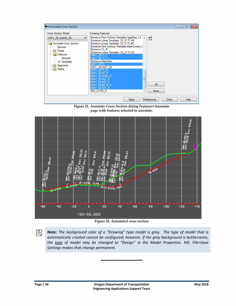
Figure 21. Annotate Cross Section dialog Features>Annotate
page with features selected to annotate.
Figure 22. Annotated cross section
Note: The background color of a “Drawing” type model is gray. The type of model that is automatically created cannot be configured; however, if the gray background is bothersome, the type of model may be changed to “Design” in the Model Properties. MS: File>Save Settings makes that change permanent.
-----------------------------------

May 2018 Oregon Department of Transportation Page | 35 Engineering Applications Support Team
Working with Reports
Creating Reports Reports on civil geometry, terrains, and corridors are created from Civil Tools>Analysis
& Reporting and also other groups.
Reports from Legacy Data (.alg, .dtm) are created using InRoads Explorer Tools>XML
Reports
Known Issue with Reports in InRoads SS4
Final Cumulative Earthwork Volumes not Totaled
When you create reports, if the final cross section has no cut or fill, the report will not show the
total quantity for that work (see example below). The workaround is to export the report data to an
XLS file and sum the table columns in Excel.
Figure 23. Grand Total line at the bottom of a report showing a known issue in InRoads SS4.
There is no total for the columns where the final cross section had no fill entries.
----------------------------------------

Page | 36 Oregon Department of Transportation May 2018 Engineering Applications Support Team
Working with Drainage
InRoads V8i SS4 Legacy Versus SS2
Drainage in SS4
The legacy InRoads V8i Drainage menu item and tab on InRoads Explorer are still there, and in
InRoads V8i SS4 you will still use them in the same manner as you have in other V8i versions. You
may load a drainage database (.sdb) into InRoads V8i SS4 and review/edit the structures as well as
view the structures in Plan View. Editing structures in the database is limited to setting a Top Height
on inlets and manholes and setting styles for display.
Storm and Sanitary Drainage in SS2
Use InRoads V8i SS2 with Storm and Sanitary to perform drainage workflows for designing
networks and to display networks in profile.
Drainage Network Display in Plan View
The ODOT preference set is configured to display drainage objects that are typically displayed in
contract plans and to use the symbology typically used for contract plans. Pipe and culvert center
lines are drawn, and cells are placed to locate manholes and inlets.
Drainage Annotation
Cells placed with the View Drainage tools display the correct size for 1”=100’ contract plans only.
You should place your drainage annotations in a separate model to avoid adding annotation scale
where it is not necessary. The annotated drainage network does not respond to annotation scale
when referenced into a model with a different drawing scale.
Use a cell scale factor (Tools>Global Scale Factors) of 0.50000000 to display drainage structures in plan
for 1"=50' scale plans.
--------------------------------

May 2018 Oregon Department of Transportation Page | 37 Engineering Applications Support Team
Working with Survey InRoads V8i SS4 does not have an Add-In for Survey. This means that the InRoads Explorer has
neither a Survey tab nor a Survey menu.
Survey tools are now available under the Civil Tools>Survey in MicroStation Tasks and the Project
Explorer has been configured to display the Survey browser.
Figure 24. The Survey Workflow in MicroStation Tasks>Civil Tools (left)
and the Survey browser in Project Explorer (right)
--------------------------------------

Page | 38 Oregon Department of Transportation May 2018 Engineering Applications Support Team
Appendix A: Launching InRoads
InRoads Shortcuts
During the installation of InRoads V8i SS4, if you have a shortcut for SS2 on your workstation, it is
removed. Two new shortcuts are created: one for SS4, named SS4_InRoads and a new desktop
shortcut for SS2, now named InRoads_SS2. The name is the only thing that distinguishes these; the
icon looks the same.
Note: If you pin a shortcut for InRoads V8i SS2 or SS4 to the task bar, the name text is not shown. Since the icons are the same, to avoid confusion you may want to only pin one of the shortcuts.
Concurrent Use of SS2 and SS4
Do not run InRoads SS4 and SS2 at the same time. This includes not running InRoads Lite (renamed
“InRoads SS2 Lite”) at the same time as InRoads SS4. Specifically, do not launch InRoads SS2 Lite
from the MicroStation ODOT menu when you have InRoads SS4 open, even though the link to open
it is there.
Launching InRoads SS4
You can launch InRoads V8i SS4 from:
The shortcut on the desktop (or any other place you put it)
The Start Menu: All Programs>Bentley>InRoads Group V8i (SELECTseries 4)
There is no “Lite” version of InRoads V8i SS4; nor any way to launch the full version of InRoads V8i
SS4 from within MicroStation.
Initial Launch Interface When InRoads SS4 opens the first time, the interface setup from the new MicroStation preference
file (UPF) for design is applied. Note that it is different than the interface for drafting. The main
features of the layout are described below.

May 2018 Oregon Department of Transportation Page | 39 Engineering Applications Support Team
Figure 25. Initial Launch Interface for InRoads SS4
Project Explorer and Element Information are docked and unpinned at the left side.
Tasks is open to Civil Tools, docked on the left and unpinned.
The Tasks> Main toolbar is docked on the right.
The InRoads Explorer window is open showing the SS4 legacy tools.
Snaps, Civil AccuDraw, Feature Definitions Toggle Bar, and Design Standards are all open and docked.
The Civil Message Center (analogous to the MicroStation message center) is docked and unpinned at the bottom.
--------------------------------------
Working Offline After launching InRoads V8i on the network one time, you are granted a 30-day use license that allows you to work offline for 30 days.
Before Working Offline
Prior to working on a laptop offline from the ODOT network, follow these steps:
1. While still connected to the ODOT network, launch Offline_Workspace from the shortcut in the Engineering folder on your desktop. This copies your Engineering

Page | 40 Oregon Department of Transportation May 2018 Engineering Applications Support Team
Workspace, along with your user customizations from your Engineering Personal Server Share, to the C:\ drive of your laptop.
When working offline after using the Offline_Workspace the workspace files are found in C:\ProgramData\odot_space.
Caution: If you don’t run the Offline_Workspace, you will be unable to run MicroStation. Instead, the following error message appears in a black text window: “ODOT Workspace not found — Refer to Support for Assistance”
When this error message appears, you will be unable to run MicroStation until you reconnect to the network.
Note: The Engineering Workspace is updated regularly. It is important to have the latest customizations and standards available. After receiving any Workspace Update email, run Offline_Workspace to copy the latest files to your computer.
2. Copy the CAD files you will need from your F:\ drive or wherever else they are stored and put them in one of the C: Drive folders described above so that you can access them while you are offline.
3. Launch MicroStation and InRoads and/or any other Bentley software you will be using while on the ODOT network.
Figure 26. Launching Offline_Workspace from the Engineering Folder
While working offline, you may get an “Activation Status” dialog that pops up and alerts you to the time remaining before you have to connect to a network and launch InRoads while online to refresh the license. Dismiss the dialog by clicking the [Try It] button.
------------------------------------

May 2018 Oregon Department of Transportation Page | 41 Engineering Applications Support Team
Appendix B: InRoads V8i SS4 files in F:\ODOT_DATA\USERCFG\InRoads\SS4
Both versions of InRoads in use by ODOT (V8i SS2 and V8i SS4), have version-specific preference files
that define how operations are performed and provide symbologies and styles for the display of
graphical elements. While the preference file for SS2 (civil.xin) may be opened with SS4, some
dialog boxes have changed, and so separate preferences for SS4 were established in a preference
file named civilSS4.xin. InRoads opens the appropriate preference file for the version that you
launch.
Files used by InRoads V8i SS4 for preferences and the template library are stored in your
engineering personal server share, F:\ODOT_DATA\USERSCFG\InRoads\SS4.
These files are delivered to consultants in the ODOT workspace that can be downloaded from
ODOT’s ftp site.
Shortcut
You can use a shortcut in the Engineering folder on your desktop to access the folder that
contains the SS4 .itl and .xin files:
1. From the Desktop (under Favorites), open the Engineering folder.
2. Double-click on the ODOT_User_Configuration shortcut to open the USERCFG folder. It
contains the InRoads folder.

Page | 42 Oregon Department of Transportation May 2018 Engineering Applications Support Team
3. Open the InRoads folder. In this you see the .xin and .itl files for InRoads SS2, and an
SS4 folder.
4. Open the SS4 folder to see the SS4 versions of the preference (civilSS4.xin) and
template library (ODOTSS4_seed.itl) files. An additional file in the SS4 folder named
SyncXS_LevelList.txt may be used to personalize the SyncXS utility.
Figure 27. Contents of ODOT_DATA_USERCFG\InRoads\SS4 folder
------------------------------------

May 2018 Oregon Department of Transportation Page | 43 Engineering Applications Support Team
Preference File (.xin)
The InRoads preference file for the SS4 version, civilSS4.xin, is refreshed with each logon so
that you always have access to the current standards.
The civilSS4.xin file may be copied into your project folder and thereafter retains project-
specific customizations. If you copy civilSS4.xin into a project folder, it is recommended that
you rename it to keynuSS4.xin.
For more information about the preference files for ODOT, see Appendix C: Preference Files (.xin).
Template Library Seed File (.itl)
A template library seed file (.itl) for ODOT use with InRoads V8i SELECTseries 4, named
ODOTSS4_seed.itl, is stored in the F:\ODOT_DATA\USERCFG\InRoads\SS4 folder. It is
recommended that you copy the ODOTSS4_seed.itl file, save it in your project directory, and
rename it according to new naming conventions.
For more information on the ODOT template libraries, see What’s in ODOTSS4_seed.itl?.
-----------------------------------------------------

Page | 44 Oregon Department of Transportation May 2018 Engineering Applications Support Team
Appendix C: Preference Files (.xin)
Preference Files
When you perform an operation in InRoads you choose Preferences to define how that operation is
to be performed. Preferences are saved to a preference file that has the extension “.xin”. A .xin
file contains InRoads settings such as:
Preference Sets
Styles
Named Symbologies
Locks
InRoads V8i SS4 uses feature definitions to define the symbology and display of civil data including terrains and geometry. The feature definitions for geometry and roadway features (both existing and design) are set to use a Native Style, which is stored in the .xin. Also included in the SS4 preference file are the feature styles used with the SS2 version of InRoads, to display the graphics from InRoads with the same symbology.
CivilSS4.xin
ODOT’s standard preference file for use in InRoads V8i SS4 is named civilSS4.xin. Every time
you log on and launch InRoads V8i SS4, a batch file places a fresh civilSS4.xin file in your
F:\ODOT_DATA\USERCFG\InRoads\SS4 folder.
You may load a different preference set by selecting the [Preferences…] button on any dialog.
The civilSS4.xin file contains two preference sets of particular importance: The ODOT
preference set, and the ODOT-Plans preference set. These are described in greater detail below.
CivilSS4.xin opens automatically when InRoads V8i SS4 is launched. It is stored separately from
the SS2 .xin file because there are some key differences in the two main preference sets for
Vertical Annotation of geometry. ODOT and ODOT-Plans have been entirely reworked for SS4 to
match the annotation from SS2.
Styles and Symbologies from the currently-loaded .xin are used any time the properties of a
feature definition are set to use "Native Style".
Can I Customize My XIN file?
Use the ODOT standard civilSS4.xin for production work unless you have a compelling reason
to do otherwise.
If you find settings that don’t match established drafting standards for contract plans, or find a need
for additional settings, please submit a change request to the EAST team so that the standard
preference file can be improved for everyone’s use.

May 2018 Oregon Department of Transportation Page | 45 Engineering Applications Support Team
Naming Customized Preference Files
If you intend to modify the standard preference files for special purposes, follow these guidelines for
renaming and file location.
If you want to create a project-specific .xin file, copy civilSS4.xin from F:\ODOT_DATA\USERCFG\InRoads\SS4 to the project location and rename it to keynuSS4.xin.
If the .xin file is for your own use with more than one project, you may find it easier to make a copy within F:\ODOT_DATA\USERCFG\InRoads\SS4 and rename it mynameSS4.xin.
Managing Customized Preference Files
Bear in mind that you are responsible for managing your custom preference files. Your
customizations could be lost in future releases if you are not careful in how you name your files and
where you store them.
Also recognize that when the standard civilSS4.xin is updated, those updates do not appear in
your customized .xin file. As important updates to preferences are made, you will need to match
them in your customized .xin file.
It is possible to copy preferences from one .xin into another using the Copy Preferences… tool. Copy
Preferences… is an Add-In which appears under the InRoads Tools menu after it is added.
Tip: If you are customizing your preferences, consider saving your changes to the ODOT preference set because the ODOT preference set is loaded initially. Saving preferences to the ODOT preference set in a custom XIN file saves the step of clicking on the [Preferences…] button in a dialog and loading another set.
Preference Sets
A preference set automates much of the decision making and ensures reproducibility and
standardization of similar projects.
For example, when using View Stationing to label stations on an alignment, there are nine tabs, each
with check boxes, radio buttons, drop-down menus, and symbology settings about which you must
make decisions. If you use a preference set, those decisions are automatically made for you, and the
choices align with ODOT standards.
ODOT Preference Set
The ODOT preference set is the preferred preference set, and is loaded by default when you launch
InRoads. Unless you change the Project Defaults, the ODOT preference set is initially loaded for
every command.
The ODOT preference set has initialized settings for more than 75% of the dialog boxes found on
InRoads’ menus. It draws plan graphics and annotation symbologies similar to contract plans, but
places on-board symbols instead of standard cells, to speed up the design process of redrawing and
annotating graphics.

Page | 46 Oregon Department of Transportation May 2018 Engineering Applications Support Team
ODOT-Plans preference set
An ODOT-Plans preference set has been created for use in drawing and annotating the design in
Plan View, using an annotation scale according to contract plans symbology. The ODOT-Plans
preference set makes all of the choices so that the stationing appearance matches the drafting
standards for contract plans as closely as possible.
Determining Command Dialog Preference Settings
You may ask: for which command dialogs does a preference set apply? In other words, for which
command dialogs is a preference set initialized (i.e., in the list opened by clicking [Preferences]).
There are two ways to find that information – (1) in any command dialog, click [Preferences…] and
see if any preferences are listed, or (2) Use the Preference Manager to see if a particular preference
is initialized for that command.
Viewing Preference Settings in Preference Manager
The tabs in the Preference Manager (Tools > Preference Manager…) correspond to the InRoads
Explorer menu items (File, Surface, Geometry, Drainage, Evaluation, Drafting, Quantities, Tools).
Figure 28. Preference Manager
To determine whether a preference set is initialized for a menu command on a menu:
1. Select the tab for that menu.
2. Select the preference set name from the drop-down list.
3. Find the command in the Commands list. If the status column shows initialized, then that
preference set is available for that command.
May 2018 Oregon Department of Transportation Page | 47 Engineering Applications Support Team
You can quickly shift from tab to tab and find commands for which the selected preference set is
initialized. The ODOT preference set is initialized for more commands than any other preference
set.
How Preferences Are Named
Preferences are generally named with the first group of characters defining functionality, such as:
CL = Geometry-related preferences
DTM = Surface related preferences
RW = Right-of-Way preferences
SURV = Survey Filing Map Preferences
A second grouping describes the preferences set. For example, within the DTM preference sets are
_BaseRock, _Existing, _Subgrade, and _Finish.
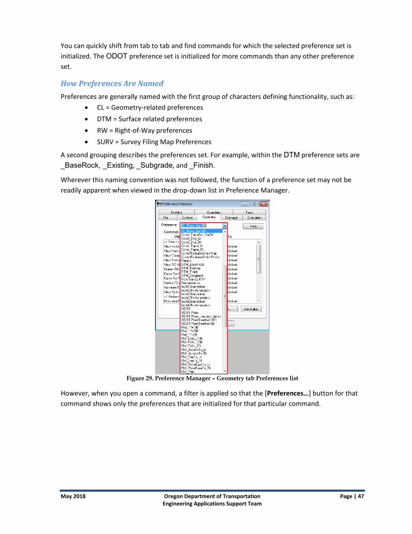
Wherever this naming convention was not followed, the function of a preference set may not be
readily apparent when viewed in the drop-down list in Preference Manager.
Figure 29. Preference Manager – Geometry tab Preferences list
However, when you open a command, a filter is applied so that the [Preferences…] button for that
command shows only the preferences that are initialized for that particular command.
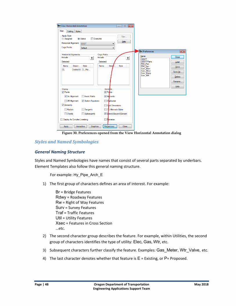
Page | 48 Oregon Department of Transportation May 2018 Engineering Applications Support Team
Figure 30. Preferences opened from the View Horizontal Annotation dialog
Styles and Named Symbologies
General Naming Structure
Styles and Named Symbologies have names that consist of several parts separated by underbars.
Element Templates also follow this general naming structure.
For example: Hy_Pipe_Arch_E
1) The first group of characters defines an area of interest. For example:
Br = Bridge Features Rdwy = Roadway Features Rw = Right of Way Features Surv = Survey Features Traf = Traffic Features Util = Utility Features Xsec = Features in Cross Section …etc.
2) The second character group describes the feature. For example, within Utilities, the second
group of characters identifies the type of utility: Elec, Gas, Wtr, etc.
3) Subsequent characters further classify the feature. Examples: Gas_Meter, Wtr_Valve, etc.
4) The last character denotes whether that feature is E = Existing, or P= Proposed.

May 2018 Oregon Department of Transportation Page | 49 Engineering Applications Support Team
Material Styles
Material styles and their matching Named Symbologies begin with MAT- and do not use the E or P
at the end of the name. These styles were created specifically for use with components used in
roadway modeling. When components of a design template are assigned an MAT- style, the
resulting component from a design surface may be displayed in Plan View or in cross sections. The
ODOTSS4_seed.itl template library contains components with MAT- styles correctly assigned.
End-Area volume reports produced after displaying design surfaces in cross section rely on the
MAT- style setting that allows the components to be displayed in the cross section.
Cross-Section Feature Styles
Certain styles were created specifically for features that might be commonly displayed or labeled in
cross sections, such as barrier, guardrail, fence, and RW labels. Styles beginning with Xsec are based
upon the Rdwy or Rw style for that particular feature, but have the cross section point defined to
place a cell in the cross section as opposed to a “plus sign”. These styles were created for both left
(_Lt) and right (_Rt), as well as for both proposed (_P) and existing (_E) features. The cells and labels
are pulled from XSEC.cel in the workspace. XSEC.cel contains more cells that could easily be used
for more styles. There are a few different kinds of curb cells and labels for EP, as well as
underground utilities.
Xsec_Barrier_Lt_E
Xsec_Barrier_Rt_E
Xsec_Barrier_Lt_P
Xsec_Barrier_Rt_P
Xsec_Guardrail_Lt_E
Xsec_Guardrail_Rt_E
Xsec_Guardrail _Lt_P
Xsec_Guardrail _Rt_P
Xsec_Fence_Label_E
Xsec_RW_Label_E
Xsec_RW_Label_P
Xsec_RW_AC_Label_P
Xsec_RW_PEase_Label_P
Xsec_RW_TEase_Label_P
Exterior Boundary and Transverse Feature Styles
Two styles, named Exterior_Boundary and Transverse_Feature, were created specifically for exterior
boundaries and transverse features. Both place only the lines connecting the points but do not
place point symbols at vertices, thereby making it easier to use the graphics drawn by these styles
for other purposes. These styles would typically be used with the legacy tool “Import Surface”.

Page | 50 Oregon Department of Transportation May 2018 Engineering Applications Support Team
Appendix D: Settings and Preferences
Settings in Seed Design Files
Model Names
Two seed design files are set up for use by ODOT designers creating design products in SS4:
seed2d.dgn and seed3d.dgn. Because designers may take advantage of dragging and dropping
from the Project Explorer to make reference attachments of civil design data, the default model in
seed3d.dgn has been named Default-3D. In SS4 you will be able to discern which view window is
displaying your 3D data, just by looking at the view window title bar. The 2D model is simply named
Default.
Figure 31. View window title bars and Project Explorer showing that
3D models have -3D in their names
Design File Settings
The command MS: Settings>Design File for both seed files (2D and 3D) contains settings that affect
angular and linear precision and formatting. The InRoads command File>Project Options… displays an
Alert dialog to remind you that these settings have moved into the .dgn so that the civil geometry
can use them.

May 2018 Oregon Department of Transportation Page | 51 Engineering Applications Support Team
Figure 32. Alert indicating that some settings have
moved from the .xin to the .dgn
In the seed files, MS: Settings>Design File>Working Units>Accuracy has been set to 0.123, and MS:
Settings>Design File>Angle Readout: Format, Accuracy, and Distance Mode have all been set so
that civil geometry data displayed in InRoads V8i SS4 matches annotation.
Figure 33. Design File dialog showing the Angle Readout
settings that affect civil geometry
The Angle Readout settings control the display of fields in commands that use an angle, but do not
limit the format of the angle input. If you prefer to input angles in decimal, do so; the DD.DDDD
format will be converted into the DD MM SS format.
Tip! For changes to Design File Settings to be retained in the .dgn from session to session, save the settings prior to exiting the file, using the command File>Save Settings.

Page | 52 Oregon Department of Transportation May 2018 Engineering Applications Support Team
InRoads V8i SS4 Default Preferences The ODOT default preferences for InRoads V8i SS4 are different than those for MicroStation and were created with designers in mind.
Figure 34. The default interface for InRoads V8i SS4 showing the InRoads Explorer.
The Legacy InRoads Explorer is not hidden and will reappear with each fresh log on. The Project
Explorer, Tasks, and Element Information are all open, docked, but unpinned, showing just the tabs,
at the left. The Main toolbox is docked at the right and several “civil” toolboxes are docked at the
bottom, including the Civil Message Center, the Feature Toggle Bar, Civil AccuDraw, and Design
Standards.
Changing Your Preferences
When you change the look of your InRoads V8i SS4 interface by pinning open tasks or opening
toolboxes, it does not affect how MicroStation V8i SS4 or InRoads V8i SS2 appears. InRoads V8i SS4
uses its own preference, docking, group and navigation files that are all named with “SS4_Civil”. SS4
is configured separately so that designers may optimize their interface for design work, separate
from drafting work.

May 2018 Oregon Department of Transportation Page | 53 Engineering Applications Support Team
Figure 35. MS: Workspace>Preferences dialog showing “ODOTSS4_Civil” in the
title bar and the name “ODOT Design Preferences”.
--------------------------------------------

Page | 54 Oregon Department of Transportation May 2018 Engineering Applications Support Team
Appendix E: Civil Standards Features and settings that have been configured by ODOT are stored in design Libraries (.dgnlib)
that use "ODOT" in the name. These are under the Civil Standards hierarchy.
The Civil Standards are loaded at launch and are accessed through the Project Explorer.
There are five important subsections to Civil Standards, described below in greater detail.
Civil Cells
Design Standards
Feature Definitions
Project Settings
Terrain Filters
Civil Cells
The .dgnlib files containing civil cells have been copied from the Bentley Examples workspace and
made available in the ODOT workspace. Civil cells created for ODOT use have names that begin with
"ODOT".

May 2018 Oregon Department of Transportation Page | 55 Engineering Applications Support Team
Figure 36. Picking an ODOT civil cell
Design Standards
The horizontal design standards delivered in ODOT_DesignStandards2012.dgnlib provide curve
radii and spiral lengths from the Superelevation & Spiral Lengths tables in Chapter 3 of the ODOT
Highway Design Manual 2012. The vertical design standards provide the maximum grade for
different highway classifications shown in chapters 5, 6, and 7 of the ODOT HDM 2012. The AASHTO
design standards for 2011 and 2004 are also included in the workspace.
Figure 37. Horizontal Design Standards list tree
Using the Design Standards Toolbar
The Design Standards Toolbar is docked by default at the bottom of the screen in InRoads V8i SS4; it
may be reopened from Tasks>Civil Tools>General Geometry.

Page | 56 Oregon Department of Transportation May 2018 Engineering Applications Support Team
It may be used in two different modes:
Set Design Standard (1) mode - used to check the curvature of an alignment against a minimum value after placement
Toggle Active Design Standard (2) mode - used to provide a default radius as you place the PIs
For either mode, when you select a horizontal design standard (3), the most conservative vertical
design standard (4) is automatically selected and displayed. You may select an exact vertical design
standard by opening the pull-down menu (5) expanding the highway classifications and choosing the
standard from the tables.
If standards are active during placement, a default 2° curve is placed at PIs with standard spiral
lengths for the selected speed. It is up to you to change the radius as you move from PI to PI. If you
use a tighter curve than 2°– the Civil Message Center displays warnings.
Note: Warnings are typically about curves being tighter than the default radius and can usually be ignored. Errors, however, mean that your design does not meet the minimum standard radius. Consult the ODOT Highway Design Manual to resolve errors.
Feature Definitions and Element Templates
Feature definitions and element templates for elements drawn by InRoads V8i SS4 are provided in
one design library named Civil_ET_FD_odot.dgnlib.
About Feature Definitions
In InRoads V8i SS4, feature definitions take the place of feature styles used by SS2. When InRoads
V8i SS4 draws graphical elements, it looks to the feature definition to determine where the element
will be drawn (e.g., 3D, Plan, Cross Section, Profile) and the source for the symbology that will be
used to display the element: Level, Color, Line Style, Weight, etc.
There are two sources for symbology: Native Style (this is named symbology sourced from the .xin)
and element templates.
Native Style is used for all ODOT linear feature definitions that were imported from the SS2 civil.xin.
Element templates provide the symbology for feature definitions for terrains, corridor graphics, and corridor meshes.
A combination of Native Style and Element Templates is used to define ODOT symbology for Components (Materials). In general, native style is used for components in profiles and Element Templates are used for components in 3D display.

May 2018 Oregon Department of Transportation Page | 57 Engineering Applications Support Team
Note: To see the properties of feature definitions, including where they source symbology, open Project Explorer>Civil Standards, open Libraries\Feature Definitions and then drill down to the Feature Definition that you want to see. Right-click on it, and select Properties.
About Element Templates
Element templates define the display for new graphical element types such as: Terrains, Corridor
Meshes, and Corridor Graphics (see below). Components use a combination of native style for
Profile display and an element template with a material assigned for 3D visualization.
Element templates are stored in the same design library as the feature definitions, but are accessed
from MS: Element>Element Templates.
Figure 38. Element Templates dialog
General Settings are used in temporary cross sections and profiles, as well as the permanent cross sections.
Calculated Feature Settings are used to display the elements in 3D and Plan.
Once an element template is used from a design library, it is written to the .dgn file and can be
edited to change the attributes.
Terrain
For each Terrain Display feature definition there is a corresponding element template. The feature
definition for a terrain controls what displays (e.g., contours, boundary, features, triangles) and the
element template defines how it appears (color, level, weight, etc.).

Page | 58 Oregon Department of Transportation May 2018 Engineering Applications Support Team
Corridor Meshes
The corridor mesh is a new element type. It is an output from corridor modeling.
ODOT has two element templates for meshes: Top Mesh and Bottom Mesh. The mesh element is
drawn with primary class graphics on Level 46 for Top Mesh and Level 47 for Bottom Mesh.
Corridor Graphics
The element templates for Corridor Graphics define how elements related to corridor modeling
display in order to graphically select and modify them.
The symbology for corridor graphics uses the Construction class and numbered levels: Level 30 -
Level 45.
Components (Mat)
ODOT has assigned materials element templates for certain components for visualization. These are
found in the Mat subfolder under Components.
Figure 39. The Mat subfolder under Components
When component graphics are displayed in a design file (e.g., by Corridor Design Stage 3 – Final),
the element template defining the 3D display is written to the .dgn. You may edit the element
template to change the assigned material.
-------------------------------------------

May 2018 Oregon Department of Transportation Page | 59 Engineering Applications Support Team
Project Settings –Design Stages
ODOT_Project_Settings.dgnlib was copied from Bentley's Examples workspace and the
Corridor Design Stages have been modified for ODOT use. Design stages range from Functional with
the least complexity and no critical sections, to six different Final stages that all include critical
sections.
Stages differ mainly in the output settings that control which graphics are displayed and are
available for cross sections.
Two of these that you may find particularly useful are:
3 - Final displays the top mesh only, features, and components which provide cross sections for a grade report or annotation.
8 - Final Components may be beneficial for quantities or visualization.
Figure 40. Element Information dialog showing the Output Settings of Corridor
Design Stage 3 – Final (left); Project Explorer Civil Standard tree is expanded to show ODOT_Project_Settings.dgnlib (right)
For each Corridor Design Stage, there is a matching Linear Design Stage, provided in order to
maintain corresponding corridor output settings to templates that are applied linearly.
--------------------------------------------

Page | 60 Oregon Department of Transportation May 2018 Engineering Applications Support Team
Terrain Filters and Filter Groups
Graphical filters and graphical filter groups are stored in ODOT_Terrain_Model_Filters.dgnlib.
The filters can also be combined into groups to form different terrains. For example, using the Road
Subgrade Terrain filter group, you can create a terrain that combines roadbed features that use the
RDWY-Subgrade feature definition, as well as features on the side slopes, such as ditches and slope
breaks, and the catch features that mark the limits of construction.
Figure 41. ODOT_Terrain_Models_Filters.dgn expanded to show terrain filters combined in
three groups for creating Existing, Road Finish, and Road Subgrade terrains
--------------------------------------------

May 2018 Oregon Department of Transportation Page | 61 Engineering Applications Support Team
Appendix F: Variables (Registry) InRoads V8i SS4 has been customized for ODOT use by setting options defined in the current user’s
computer registry. The default variable settings are recommended by the InRoads Standards
Committee and should provide the optimum performance in the ODOT environment. The default
behavior is set at the time of logon using a logon script file. The behavior may be modified during an
InRoads session using the “Variable Manager” in the InRoads Tools menu.
------------------------------------------