ODC 3453135556 eng - Garage Doors from Overhead Door ... · 3453135556 Included Wall Control MUST...
28
3453135556 Included Wall Control MUST be installed prior to operation of this Garage Door Operator Safe-T-Beam ® Safety Reverse System Must be installed to close door SAVE THIS MANUAL FOR FUTURE REFERENCE NOTE: Your Operator comes with a Rail Assembly which is standard for up to a 7 foot 6 inch high door. An extension kit for an 8 foot high door is available. For Answers and Assistance: 1.800.929.3667 or visit www.overheaddoor.com Includes Remote Control and SERIES II Electronics Series OCG
Transcript of ODC 3453135556 eng - Garage Doors from Overhead Door ... · 3453135556 Included Wall Control MUST...

3453135556
Included Wall Control MUST be installed prior to operation of this GarageDoor Operator
Safe-T-Beam® Safety Reverse System Must be installed to close door
SAVE THIS MANUAL FOR FUTURE REFERENCE
NOTE: Your Operator comes with a Rail Assembly which is standard forup to a 7 foot 6 inch high door. An extension kit for an 8 foot high door is available.
For Answers and Assistance:
1.800.929.3667or visit www.overheaddoor.com
Includes Remote Controland SERIES II Electronics
Series OCG

6 To avoid damage to your door and/or operator, make sure you disable any door
locks prior to installing your operator.
1 Check your ceiling where the power head of your new unit will be mounted.
Plan how you will be mounting the power head.It is possible that ceiling joists may not be in theexact position needed with respect to the garagedoor operator. In any case, it may be necessaryto add an additional bracket and fasteners (notincluded with your new door operator kit).
2 Check the wall directly above the garagedoor. The door operator’s header bracket
must be securely fastened to this wall. Insurethat the structure will provide a strong mountinglocation.
3 Check to see if the mounting location for the Safe-T-Beam® System “STB” is
clear from obstruction and has a wood surface available for attaching the “STB”brackets. The brackets may also be attached toconcrete if necessary but extra tools and specialfasteners (not supplied) will be required.
NOTE: 1-1/2" “STB” bracket adapters are available through your local Overhead door Dealer.
4 Is your garage door made of light-weight steel, aluminum, fiberglass
or glass panels? Additional support bracingmust be added to these type doors. If this is thecase, please contact the door distributor or manufacturer so that they can furnish you with a“bracing kit.”
7 Insure that your door is properly balanced and moving freely. SEE WARNING BELOW.
8 (NOT SHOWN) If your garage does not havea separate entry door, you might want to
consider an emergency release kit (GER-2) for installation on your garage door. See page A at thecenter of this manual.
5 You need a 110-120 Volt power supply available. If you plan to plug the unit into a
standard electrical outlet, is one available? The outlet should be no more than about 3 feet from thepower head once it is mounted. (The cord is 4 ft. inlength.) SEE WARNING BELOW.
2
PRE-INSTALLATION CHECK LIST FOR HELP-1.800.929.3667 OR OVERHEADDOOR.COM
Things to consider if you are planning to “do-it-yourself.”In many cases you will be replacing an existing door operator with a new one, however, if thiswill be the first operator installed there are some pre-installation issues which need to beaddressed. They are as follows:
The Overhead Door Corporation recommends that you read and fully understandall information and instructions contained herein before choosing a “Do-it-yourself” installation. Any questions should be directed to Overhead Door Corp. or an authorizedOverhead Door Dealer.
If your door sticks, binds, or is out of balance, have it adjusted by a professional.Door springs, cables, pulleys, brackets andassociated hardware are under extreme tension and can cause serious injury ordeath.
WARNING
DO NOT USE EXTENSION CORD!Extension cords can cause dangerousoverheating conditions.DO NOT USE PORTABLE GENERATOR!This product is designed to operate onstandard house current. Do not use alternate power supplies.
WARNING
(The issue numbers below refer to the circled numbers in the illustrations on page 3.)

3
7
TYPICAL SECTIONAL DOOR INSTALLATION FOR HELP-1.800.929.3667 OR OVERHEADDOOR.COM
TYPICALSUPPORTBRACKET
EXTENSION SPRINGOR
TORSION SPRING
SAFE-T-BEAM®
BRACES
ADDEDHEADER BRACKETMOUNTING BOARD
TYPICAL 1-PIECE DOOR INSTALLATION
48" POWER CORDTO
120V GROUNDEDOUTLET
4
1
36
2
3
5
SECTIONAL DOOR 1-PIECE DOOR

4
SECTION . . . . . . . . . . . . . . . . . . . . . . . . . . . . . . . . . . . . . . . . . PAGE
PRE-INSTALLATION CHECKS . . . . . . . . . . . . . . . . . . . . . . . . . . 2-3
OPERATOR FEATURES. . . . . . . . . . . . . . . . . . . . . . . . . . . . . . . . . 4
SAFETY FEATURES. . . . . . . . . . . . . . . . . . . . . . . . . . . . . . . . . . . . 4
TOOLS RECOMMENDED. . . . . . . . . . . . . . . . . . . . . . . . . . . . . . . . 5
PARTS IDENTIFICATION . . . . . . . . . . . . . . . . . . . . . . . . . . . . . . 5-7
SAFETY INFORMATION . . . . . . . . . . . . . . . . . . . . . . . . . . . . . . . . . 7
OPERATOR . . . . . . . . . . . . . . . . . . . . . . . . . . . . . . . . . . . . . . . . . . . . . 1 ASSEMBLY. . . . . . . . . . . . . . . . . . . . . . . . . . . . . . . . . . . . 8-10
2 INSTALLATION . . . . . . . . . . . . . . . . . . . . . . . . . . . . . . . . 11-14
ELECTRICAL INSTALLATION . . . . . . . . . . . . . . . . . . . . . . . . . 15-18
3 SAFE-T-BEAM ® SYSTEM INSTALLATION . . . . . . . . . . 15-16
4 WALL CONTROL INSTALLATION. . . . . . . . . . . . . . . . . . . . 17
5 CONNECT OPERATOR TO POWER . . . . . . . . . . . . . . . . . 18
ADJUSTMENTS . . . . . . . . . . . . . . . . . . . . . . . . . . . . . . . . . . . . 19-21
6 LIMIT SWITCHES & FORCE ADJUSTMENT . . . . . . . . . . . 19. CONTACT REVERSE . . . . . . . . . . . . . . . . . . . . . . . . . . . . . 20
7 PROGRAMMING REMOTE CONTROLS . . . . . . . . . . . 20-21
8 BATTERY/VISOR CLIP INSTALLATION. . . . . . . . . . . . . . . 21
9 LIGHT BULB AND LENS INSTALLATION. . . . . . . . . . . . . . 21
SAFETY INSTRUCTIONS . . . . . . . . . . . . . . . . . . . . . . . . . . . . . . . 22
MAINTENANCE & TROUBLESHOOTING . . . . . . . . . . . . . . . 22-24
SAFE-T-BEAM ® . . . . . . . . . . . . . . . . . . . . . . . . . . . . . . . . . 22
OPERATOR /RADIO . . . . . . . . . . . . . . . . . . . . . . . . . . . . . . 23
WIRING DIAGRAM . . . . . . . . . . . . . . . . . . . . . . . . . . . . . . . 24
WARRANTY . . . . . . . . . . . . . . . . . . . . . . . . . . . . . . . . . . . . . . . . . 26
ACCESSORIES . . . . . . . . . . . . . . . . . . . . . . . . . . . . . . . . . . . . . . . . A
TABLE OF CONTENTS OPERATOR FEATURESCODEDODGER® Rolling Code Security System.An electronic rolling code system that enhances the security ofthe door operator by continuously changing the access codeeach time the remote control is used. The door operatorresponds to each new code only once. An access code copiedfrom a working system and tried again will not control the dooroperator.
CODEDODGER® 1, 2 or 3-Button Remote Control (includedwith some models).Operates 1, 2 or 3 garage doors from car.
Lighted Wall Button*.Operates door operator from inside garage.
Lighted Wall Console* (included with some models).Security vacation lock switch disables all controls. LEDIndicator shows whether system is locked or unlocked. Makesconsole easy to find in dark. Controls door operator from insidegarage. Independent light control allows convenient manualcontrol of the automatic lighting system.
NOTE: Your garage door operator may not come with all aboveitems included as standard equipment.
*Operator MUST be installed with the included Wall Control.
SAFETY FEATURES
Safe-T-Beam® (STB) Non-Contact Reversing System**.Puts an invisible beam across the door opening. The door stopsand reverses to the full open position if anything passesthrough the beam. Red and green LED indicators provide a selfdiagnostic code if an operational problem exits.
Safe-T-Reverse® Contact Reversing System.Automatically stops and reverses a closing door within 2 seconds of contact with an object.
Safe-T-Stop® Timed Reversed System.Automatically opens a closing door if it fails to close completelywithin 30 seconds.
Force Guard® Control.Features adjustable open and close force settings. For maximum safety, these must be set to the minimum forcerequired to fully open and close the door.
Relay Monitoring System.Automatically stops and reverses a closing door if the closingrelay malfunctions.
Watch Dog® Monitoring System.Automatically stops and reverses a closing door if the Safe-T-Beam System** has an operational problem.
Automatic Lighting System.One bulb lighting supplies up to 100 Watts of light for saferevening exits and entries. Turns on when door is activated andautomatically turns off 5 minutes later.
Manual Emergency Release.Manually releases door from door operator. Use during a powerfailure or other emergency to allow manual opening and closingof door.
**Safe-T-Beam® Safety Reverse System MUST Be Installed To Close door.

5
TOOLS RECOMMENDED FOR HELP-1.800.929.3667 OR OVERHEADDOOR.COM
5/32" Drill Bit 7/16" and 9/16"SocketsStep ladder
Drill
Ratchet Carpenter’s levelPencil
Tape measure Wire strippersPhillips screwdriver
Adjustable wrench
PARTS IDENTIFICATION - Not Shown Full Size .
30
40Single-buttonremote control
Multi-buttonremote control
OR
38
44
29
36 35
33
31
32
37
FASTENERS - Shown Full Size . See Parts List for description.
Lag screw - 1/4" x 2"
[22]
Screw - #8-32 x 1"
[39]Self-drilling Screw
1/4"-20 x 3/4"
[42]Nut - 1/4"-20
[10]Cotter pin[25]
Clevis pin[24]
Wire clip[41]
Bolt - 3/8"-16 x 7/8"
[27]
Nut - 3/8"-16
[28]Bolt - 1/4"-20 x 5/8"
[9]
34
Wall console
Wall button
Nut - 5/16"-18
[47]
#6 x 1-1/4" Pan Head Phillips
Screw Safety BrochureEntrapment Warning
Label
#10"-16 x 1-1/4"Machine Screw
Source STB(Red LED)
Sensor STB(Green LED)
Wire
STB Bracket
Insulated Staple
Bolt - 5/16"-18 x 3/4"
[46]
33
#6 x 1-1/4" Pan Head Phillips
Screw

6
Item Part Name Number Required
1 Power head assembly (box) 12 Boom assembly (box) 13 Boom (box) 19 1/4"-20 x 5/8" hex head bolt (blue bag) 410 1/4"-20 hex flange nut (blue bag) 411 Carriage assembly (box) 112 Boom strap (blue bag) 113 Limit switch OPEN (white wire)(green bag) 114 Limit switch CLOSE (brown wire)(green bag) 115 Release cord (green bag) 116 Release knob (green bag) 117 Emergency release tag (green bag) 118 Header bracket (orange bag) 120 Door bracket (orange bag) 122 1/4" x 2" lag screw (orange bag) 823 Straight door arm (box) 124 Clevis pin (yellow bag) 225 Cotter pin (yellow bag) 226 Curved door arm (box) 127 3/8"-16 x 7/8" hex head bolt (yellow bag) 2
PARTS LIST
1-PIECE BOOM HARDWARE EXPLODED VIEW FOR HELP-1.800.929.3667 OR OVERHEADDOOR.COM
[2]
10
13
39
3
9
11
25
15
16
23
28
17
27
25
26
42
24
20 12
1847
22
9
10
39
4114
22
Item Part Name Number Required
28 3/8"-16 hex flange nut (yellow bag) 229 Wire (box) 130 Insulated staple (red bag) varies/model31 Wall button (red bag) varies/model32 Wall console (box) varies/model33 No. 6 x 1-1/4" flat head phillips screw (red bag) varies/model34 Entrapment WARNING label (manual) 135 Safe-T-Beam (STB) sensor (green LED)(box) 136 Safe-T-Beam (STB) source (red LED)(box) 137 Safe-T-Beam (STB) bracket (yellow bag) 138 Remote operator (box) varies/model39 #8-32 x 1" machine screw (green bag) 240 Safety & maintenance guide (manual) 141 Wire clip (wide)(green bag) varies/model42 1/4"-20 x 3/4" self-drilling screw (orange bag) 344 #10-16 x 1-1/4" phillips hex head screw (yellow bag) 446 5/16"-18 x 3/4" hex head bolt (orange bag) 347 5/16"-18 hex flange nut (orange bag) 4
1

Power Head Assembly
1J
1N
1X
1L
1N
1E
1K
1D
1A
1N
1H
1B
1Q1G1D
1F
49
1P
1M
1N
7
POWER HEAD EXPLODED VIEW
Item Part Name1 Power head assembly1A Cover (by series/model)1B Front panel assembly1D Motor parts1E Circuit board assembly1F Capacitor (by series/model)1G Opto wheel (not shown)1H Carriage slide1J Chain1K Circuit board bracket1L Drive module1M Terminal strip1N No. 8 x 3/4" hex washer head screw1P Shock absorption stop (not shown)1Q Motor mount bracket (not shown)1X Chassis49 Lens
POWER HEAD PARTS LIST (pre-assembled)
Garage doors are large, heavy objects that move with the help of springs underhigh tension and electric motors. Since moving objects, springs under tension,and electric motors can cause injuries, your safety and the safety of othersdepend on you reading the information in this manual. If you have questions or donot understand the information presented, call your nearest service representative. Ifyou have questions or do not understand the information presented, contactOverhead Door Corp. or an authorized Overhead Door Dealer.
In this section and those that follow, the words Danger, Warning, and Cautionare used to emphasize important safety information. The word:
DANGER means that severe injury or death will result from failure to followinstructions.
WARNING means that severe injury or death can result from failure to followinstructions.
CAUTION means that property damage or injury can result from failure to follow instructions.
The word NOTE is used to indicate important steps to be followed or important considerations.
OVERVIEW OFPOTENTIAL HAZARDS
SAFETY INFORMATION
POTENTIALHAZARD EFFECT PREVENTION
Keep people clear of opening while door ismoving.
Do Not allow children to play with the dooroperator.
Do Not operate a door that jams or onethat has a broken spring.MOVING DOOR
WARNING:Can Cause
Serious Injuryor Death
Turn off power before removing operatorcover.
When replacing cover, make sure wiresare not pinched or near moving parts.
Operator must be properly grounded.ELECTRICALSHOCK
WARNING:Can Cause
Serious Injuryor Death
Do Not try to remove, repair or adjustsprings or anything to which door springparts are fastened, such as, wood blocks,steel brackets, cables or other like items.
Repairs and adjustments must be madeby a trained service person using propertools and instructions.
HIGHSPRING
TENSION
WARNING:Can Cause
Serious Injuryor Death
[1]

FIG. 1-2 Align arrow.
FIG. 1-1 Attach boom strap.
8
OPERATOR ASSEMBLY FOR HELP-1.800.929.3667 OR OVERHEADDOOR.COM1
NOTE:Boom assemblies are for7 foot 6 inch highdoor.An extension kit for an 8 foot high door is available.
OPEN BLUE PARTS BAG
1. Attach boom strap (Fig. 1-1).• Place boom strap against boom so that projection
on strap mates with second hole from end of boom.– Place 2 bolts (9) through boom strap and boom.– Ignore fourth hole. (See NOTE)– Securely tighten bolts and nuts (10).
NOTE: Your boom has 4 holes in the boom strapend. The hole furthest away from the end is for anextension kit if needed.
Drive chain can slide out of booms. Do not run until operatoris fully assembled.
CAUTION
Make sure that the carriage magnet is in place in thetop of the carriage slide.
CAUTION
[10][9]
BOOM ASSEMBLY: Use a clean, flat surface.
Boom is up-sidedown
2. Slip carriage into carriage slot of boom.• Flip the boom assembly up-side down.• Place emergency release lever in “release”
position (See below).– Check arrow on the side of carriage points
toward door end of boom.– Slide carriage into boom at power head end
(Fig. 1-2).– Flip boom assembly right-side up.
Lever in release position.
1/4"-201/4"-20 x 5/8"
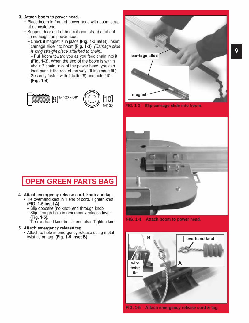
FIG. 1-5 Attach emergency release cord & tag.
9
3. Attach boom to power head.• Place boom in front of power head with boom strap
at opposite end.• Support door end of boom (boom strap) at about
same height as power head.– Check if magnet is in place (Fig. 1-3 inset). Insert
carriage slide into boom (Fig. 1-3). (Carriage slideis long straight piece attached to chain.)– Pull boom toward you as you feed chain into it. (Fig. 1-3). When the end of the boom is within about 2 chain links of the power head, you can then push it the rest of the way. (It is a snug fit.)
– Securely fasten with 2 bolts (9) and nuts (10) (Fig. 1-4).
OPEN GREEN PARTS BAG
FIG. 1-3 Slip carriage slide into boom.
FIG. 1-4 Attach boom to power head.
magnet
4. Attach emergency release cord, knob and tag.• Tie overhand knot in 1 end of cord. Tighten knot.
(FIG. 1-5 inset A).– Slip opposite (no knot) end through knob. – Slip through hole in emergency release lever
(Fig. 1-5). – Tie overhand knot in this end also. Tighten knot.
5. Attach emergency release tag. • Attach to hole in emergency release using metal
twist tie on tag. (Fig. 1-5 inset B).
[10][9]
carriage slide
wiretwisttie
overhand knotB
A
1/4"-20
1/4"-20 x 5/8"

10
7. Attach limit switch wires.• Uncoil limit switch wires.
– Place into channels located along top of boom.– Run wires back to power head through hole in top
of power head (Fig. 1-8).– Use wire clips to hold wires in place (Fig. 1-9).
• Attach limit switch wires to terminals on power head (Fig. 1-10).– White wire (“OPEN”) to terminals #4 and #5. – Brown wire (“CLOSE”) to terminals #5 and #6.
• Bundle extra wire and lay it on top of power head (Fig. 1-10 inset).
6. Attach limit switches.2 switches included, “CLOSE” limit switch (brown wire) and “OPEN” limit switch (white wire) (Fig. 1-6).
• Turn set screws (39) into threaded holes, just enough so screw stays in place. (Fig. 1-6).
• Point arrow on top “CLOSE” limit switch toward door end of boom.– Place “CLOSE” limit switch (Brown wire) on boom
about 12” from boom strap (Fig. 1-7). – Gently tighten set screw enough to keep switch
from moving.• Point arrow on top “OPEN” limit switch toward
door end of boom.– Place “OPEN” limit switch (white wire) on boom
where chain attaches to carriage slide. (Near the power head.)
– Gently tighten set screw enough to keep switch from moving.
FIG. 1-6 Identify limit switches / insert set screws.
FIG. 1-7 Place limit switches.
FIG. 1-9 Wire clips.
FIG. 1-8 Run wire to power head.
FIG. 1-10 Attach wire at power head terminals.
[39]
[41]
BundleWire
hole
4
5
6
#8-32 x 1"

FIG. 2-1 Finding highest point of travel (sectional).
11
INSTALLATION FOR HELP-1.800.929.3667 OR OVERHEADDOOR.COM2I M P O R TA N T
1. READ AND FOLLOW ALL SAFETY, INSTALLATION AND OPERATION INSTRUCTIONS. If you have questions or do not understand an instruction, call Overhead Door Corp. or an authorized Overhead Door Dealer.
2. Do Not install operator on an improperly balanced door. An improperly balanced door could cause severe injury. Repairs and adjustments to cables, spring assembly, andother hardware must be made by a trained service person using proper tools and instructions.
3. Remove all ropes and disable all locks connected to the door before installing operator.
4. Install door operator 7 feet or more above floor. Mount emergency release knob 6 feet above floor.
To reduce the risk of severe injury or death:WARNING :
5. Do Not connect the operator to the source of power until instructed to do so.
6. Locate the control button:• Within sight of door.• At minimum height of 5 feet, so small children cannot
reach it.• Away from all moving parts of the door.
7. Install the Entrapment WARNING Label next to the wall button or wall console. Install the emergency release tag on, or next to, the emergency release.
8. The operator must reverse when the door contacts a 1-1/2 inch high object on the floor at the center of the doorway. This is the size of a 2” x 4” board laid flat.
HEADER AND DOORMOUNTING BRACKETS:
1. Finding header bracket mounting location.• Close garage door.
– Use a pencil. - Mark center of garage door (one-half overall
width) with 6” vertical line at top edge of door.- Continue this line on wall above door for
about 12" (Fig. 2-1).• Raise garage door until top edge of door
reaches its maximum height (Fig. 2-2).• Place door at highest point.
– Measure height from top edge of door to floor.• Close door again.• Mark height measurement on wall above door.
– Make your mark across vertical line made earlier.
• Marking final height:
The 2 basic types of garage door mechanisms are:Track guided doors–have rollers on each side which ride in “tracks” to guide the door up and down.Trackless doors–swivel on large spring loaded hinges as the door opens and closes. For track guided – add 2-1/2" to height mark just made on wall. This is location for header bracket.
NOTE: If spring or its shaft is in way, measure 2-1/2"above spring or shaft and mark this height as yourlocation for header bracket.
For trackless – add 6"- 12” to your height mark just made on the wall. This is location forheader bracket.
FIG. 2-2 Finding highest point of travel (1-piece).
FIG. 2-3 Final height mark.
Header bracket must be fastened to garage framing. Do Not fasten to drywall, particle board, plaster or othersuch materials.
CAUTION
top of door
from here tofloor
from here tofloor
final heightmark

12
FIG. 2-4 Adding mounting surface.
[22]
Doors made of masonite, lightweight wood, fiberglass, andsheet metal must be properly braced before mounting dooroperator. Contact door manufacturer or distributor for a bracingkit. The Overhead Door Corporation is not responsible fordamage caused due to improperly braced door.(Fig. 2-6)
CAUTIONFIG. 2-5 Header bracket in place (3 methods).
FIG. 2-6 Examples of door bracing.
FIG. 2-7 Mounting door Bracket (sectional).[42]
Carriage bolt & nut.
preferred
1 2 3
FIG. 2-7B Mounting door Bracket (one-piece).
on top edge at top of back
bolted to studs in wall
NO SLOT
1/4" x 2"
1/4"-20 x 3/4"
even with orabove top roller
[22] 1/4" x 2"
NOTE: If header bracket location needs to beabove header for garage door opening, you need toadd a “mounting surface.” A 2" x 6" board securelyattached (fasteners not included) across wall studson either side of your mark is sufficient (Fig. 2-4).
OPEN ORANGE PARTS BAG2. Mounting the header bracket.NOTE: Although header bracket may be orientedseveral ways, method 1 is preferred if possiblebecause of added strength over other methods(Fig. 2-5).
• Hold header bracket against wall (Fig. 2-5).– Place left edge on vertical line. – Bottom edge on final height line.
• Mark screw hole locations on wall.• Drill 5/32" pilot holes at each screw hole mark.
– Fasten header bracket with 3 lag screws (22)(Fig. 2-5).
DOOR BRACKET:
3. Finding door bracket mounting location.• Door bracket is mounted as high on door as
possible along vertical centerline.NOTE: In the case of sectional type doors, doorbracket must be mounted NO LOWER THAN top setof rollers (Fig. 2-7).For 1-piece doors, door bracket must be mounted attop edge of door.4. Mounting the door bracket.
• Proper bracing should be verified at this point. – Align door bracket centered on your
vertical centerline. – Attach using 3 self-drilling screws (42).– Use lag screws (22) for solid wooden doors.
NOTE: For solid wood doors, carriage bolts WITHOUT SLOTTED HEADS (not included, but available by calling the Overhead Door help line) maybe used for attaching door bracket.

Mounting Straps
[22]
13
MOUNTING THE OPERATOR:1. Getting Started.
• Position boom/power head assembly (Fig. 2-7).– Boom strap leaning on wall next to
header bracket.– Place material on floor under power head to
protect from scratching. (A box, stool, or similardevice may be needed to clear a torsion spring, as shown.)
2. Mounting the assembly.• Attach boom strap to header bracket using nut (47)
(Fig. 2-7 inset). FINGER TIGHT ONLY.
• Support power head on step-ladder.
NOTE: Before final attachment to ceiling, insure thatassembly is in proper alignment (Fig. 2-9).
• Attach mounting straps to ceiling using lag bolts (22) (Fig. 2-10).
• Set height of power head according to following: – Track guided doors.
- Boom must clear door at highest point of travel.
- Be level or, power head slightly below level.– Trackless doors.
- Boom must clear door at highest point of travel by 1" to 1-1/2".
• Securely tighten power head mounting bolts (46)and nuts (47).
• Lower door.• Fully tighten boom strap nut. • DO NOT PLUG UNIT IN YET!
3. Adjusting length of emergency release cord.• Check release knob height.
– Low enough you can reach it.– High enough to clear your vehicle, but
NO HIGHER THAN 6 FEET ABOVE FLOOR.• Tie a new overhand knot where desired.
– Cut off any extra cord.
YES NONO
FIG. 2-10 Mounting the power head.
ANGLE IRON ON FINISHED CEILING
Attach angle iron to beams
UNFINISHED OR OPEN BEAM
Extra framingnot needed
Extra framingNEEDED
VIEW FROM ABOVE(not to scale)
[22]
[22]
[46] [47]
[47]
90°
DOOR
HEADER BRACKET
DRYWALL
[46 & 47][46 & 47]
5/16"-18 5/16"-18 x 3/4"
5/16"-18
1/4" x 2"
FIG. 2-7 Position assembly.
FIG. 2-9 Operator must be aligned.
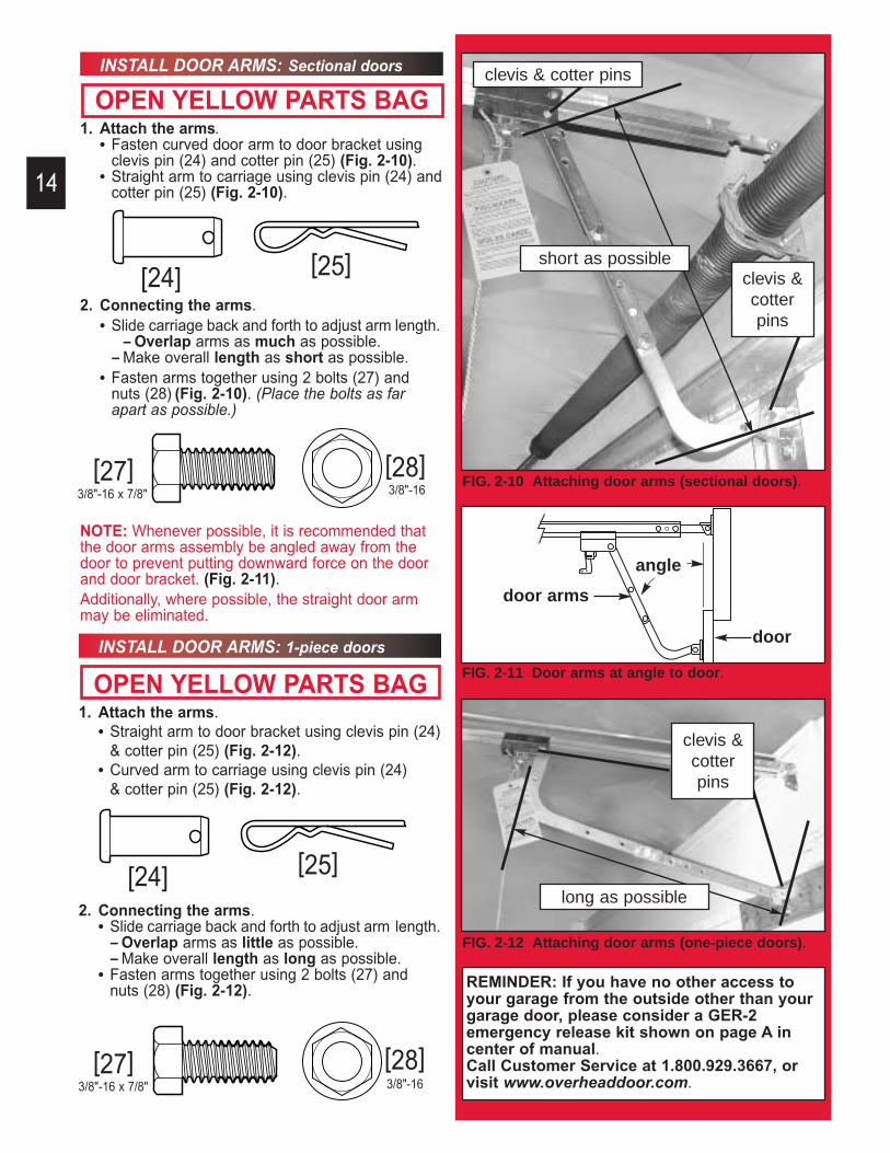
INSTALL DOOR ARMS: Sectional doors
OPEN YELLOW PARTS BAG1. Attach the arms.
• Fasten curved door arm to door bracket usingclevis pin (24) and cotter pin (25) (Fig. 2-10).
• Straight arm to carriage using clevis pin (24) andcotter pin (25) (Fig. 2-10).
2. Connecting the arms.• Slide carriage back and forth to adjust arm length.
– Overlap arms as much as possible. – Make overall length as short as possible.
• Fasten arms together using 2 bolts (27) and nuts (28) (Fig. 2-10). (Place the bolts as far apart as possible.)
NOTE: Whenever possible, it is recommended thatthe door arms assembly be angled away from thedoor to prevent putting downward force on the doorand door bracket. (Fig. 2-11).Additionally, where possible, the straight door armmay be eliminated.
[25][24]
FIG. 2-10 Attaching door arms (sectional doors).[27] [28]
INSTALL DOOR ARMS: 1-piece doors
OPEN YELLOW PARTS BAG1. Attach the arms.
• Straight arm to door bracket using clevis pin (24)& cotter pin (25) (Fig. 2-12).
• Curved arm to carriage using clevis pin (24) & cotter pin (25) (Fig. 2-12).
2. Connecting the arms.• Slide carriage back and forth to adjust arm length.
– Overlap arms as little as possible.– Make overall length as long as possible.
• Fasten arms together using 2 bolts (27) and nuts (28) (Fig. 2-12).
[25][24]
FIG. 2-12 Attaching door arms (one-piece doors).
14
REMINDER: If you have no other access toyour garage from the outside other than yourgarage door, please consider a GER-2 emergency release kit shown on page A incenter of manual.Call Customer Service at 1.800.929.3667, orvisit www.overheaddoor.com.
[27] [28]
short as possible
long as possible
clevis & cotter pins
clevis &cotterpins
clevis &cotterpins
3/8"-16 x 7/8" 3/8"-16
3/8"-16 x 7/8" 3/8"-16
FIG. 2-11 Door arms at angle to door.
door arms
door
angle

3. Wiring. • Routewires (29)using either method shown (Fig. 3-5).• Wires along boom are held in place with
wire clips.
– Wires can be slipped under the wire clips already in place.
15
SAFE-T-BEAM ® SYSTEM INSTALLATION FOR HELP-1.800.929.3667 OR OVERHEADDOOR.COM3
NOTE: The operator will not close the door automatically unless the Safe-T-Beam® System isinstalled.1. Mounting brackets.
• Mark both sides of garage door frame or wall 5" above floor. (Fig. 3-1).
• Hold bracket against door frame or wall.– Check brackets extend out from wall far
enough that tongue of bracket is beyond door, tracks or any door hardware.
– If not:- “STB” bracket extensions are available
at local dealer. - Blocks of wood, etc. may be substituted for
extensions.• Center bracket on your mark (Fig. 3-2). • Fasten each with 2 screws (44) (Fig. 3-2).
NOTE: Mounting brackets can be attached to thefloor using concrete anchors (not provided).2. Mounting “STB” source and sensor.
• If garage has only one garage door.– Determine which side of garage receives most
direct sunlight (Fig. 3-4).– Red LED should always be on sunny side
whenever possible (Fig. 3-4). • For multiple doors.
– Preventing crossed signals is critical.– Place source and sensor modules on adjacent
doors facing in opposite directions (Fig. 3-4).NOTE: To help prevent interference from sun, “STB”sensors (Green LED) may be placed further away fromthe door opening where they will spend more time inshadows.
• Slide source/sensor onto tongue of bracket until it clicks into place (Fig. 3-3).
There should be no electrical power to the operatorwhile installing Safe-T-Beam System® wires. If youhave plugged in the power cord—UNPLUG IT NOW.
WARNING
FIG. 3-1 Mark door frame.
FIG. 3-2 Mountbrackets.
FIG. 3-3 Attaching “STB’s” to brackets.
[41]
FIG. 3-5 “STB” wiring methods.
SensorSource
RedGreen
PowerHead
SensorSource
RedGreen
PowerHead
A B
Dashed Line = striped wireSolid Line = white wire
tongue
mark
center ofbracket
FIG. 3-4 “STB” locations.
#10"-16 x 1-1/4" [44] SUN
ONE DOORGARAGE
THREE DOORGARAGE
REDLED
REDLED
GREENLED
REDLED
GREENLED
GREENLED
GREENLED
REDLED
REDLED
REDLED
GREENLED
GREENLED
TWO DOORGARAGE

FIG. 3-8 Terminal attachments at power head.
OPEN RED PARTS BAG3. Wiring (cont’).
• Securely fasten wires to wall as you go.– Use insulated staples (included).
– Staples should be snug only.
16
• Make wire attachments at “STB’s.”– Splitting and stripping wire ends to be
connected as shown (Fig. 3-6).– Loosen terminal screws. – Insert wire under flat plate and tighten screw.
It does not matter which wire, white or striped, goes on which terminal (Fig. 3-7).
• Make wire attachments at power head.– “STB’s” are connected to terminals #2 and #3
on power head (Fig. 3-8).4. Check the following.
• Insure that no part of door or its hardware is in path between lenses of source and sensor.
• Insure that tops of lenses are between 5"-6" above the floor (Fig. 3-9). The brackets are flexible, and can be adjusted slightly if needed.
NOTE: “STB” alignment check must be performed following connection to electrical power (see page18).DO NOT PLUG IN YET!
Staples which are too tight can cut or pinch wires. Cut orpinched wires can cause the “STB” System to stop working.When using the insulated staples, make sure you fastenthem only as tightly as needed to hold the wire snugly.
CAUTION
[30]
FIG. 3-7 Terminal attachments at STB.
FIG. 3-9 Check lens height.
top edge of lensbetween 5" - 6"
above floor.
FIG. 3-6 Splitting and stripping.
2
3

FIG. 5-1 Terminal attachments at power head.
WALL CONTROL INSTALLATION FOR HELP-1.800.929.3667 OR OVERHEADDOOR.COM4
1. Finding the mounting location.• Pick a convenient location for mounting
wall control. – Location you choose should be in direct sight
of door. – It should be at least 5' above floor to prevent
small children from operating door.– It must be away from any moving parts. (You
should not be able to reach the door while standing at wall control.)
2. Wiring.• Run wire from power head to wall control.• Securely fasten to ceiling using insulated
staples provided.• Split and strip ends of wire (Fig. 4-5). • On power head:
– Attach the striped wire to terminal #1 andwhite wire to terminal #2 (Fig. 5-1).
• On back of wall control:– Attach striped wire to terminal “B”, and
white wire to terminal “W.” (Fig. 5-2).3. Mounting.
• Fasten wall control to wall with 2 screws (either wall button or console use 33)(Fig. 5-3).
• Remove protective backing from “entrapment” warning label (Fig. 5-4).– Stick label on wall near wall control.
NOTE: Additional wall controls are available fromyour dealer. ONLY ONE OF YOUR WALLCONTROLS MAY BE THE LIGHTED TYPE. If youhave a lighted wall control, all your additional controlsmust be un-lighted. More than one lighted wall control per operator will cause a malfunction.
Verify there is no power to the operator beforeinstalling wall control wires.
WARNING
Use of any wall control other than the type supplied will prevent the light from working andcould cause the door to operate on its own.Cut or pinched wires can cause the wall control tostop working. When using the insulated staples,make sure you only pound them in as far as needed to hold the wire snugly.
CAUTION
FIG. 5-2 Wall control wire attachment.
FIG. 5-3 Mounting wall control.
17
[33]
FIG. 5-4 Entrapment warning label.
button console
1
2
#6 x 1-1/4"

18
CONNECTING TO POWER FOR HELP-1.800.929.3667 OR OVERHEADDOOR.COM5
1. Plug the operator into a properly grounded electrical outlet.
2. Check Safe-T-Beam® alignment (Fig. 6-3).
To reduce the risk of electrical shock, this equipment has a grounded type plug that includesa third (grounding) pin. This plug will only fit agrounded type outlet. If you do not have a grounded outlet, contact a qualified electrician toinstall one. DO NOT alter the plug in any way. Thedoor operator must be properly grounded in orderto prevent personal injury and damage to the components.
WARNING
FIG. 6-1 Removing motor cover.Check local building codes to make sure that youare not required to have your garage door operatorpermanently wired, with circuit breaker protection.If permanent wiring is required, have this installedby a qualified electrician.
CAUTION
1. Instructions for electrician.• Remove power from circuit.• Remove motor cover (Fig. 6-1).
– Removing hex head screw located in center on bottom of cover.
– Slide cover down and off.• Remove and throw away existing power cord.• Remove 7/8" knockout plug (Fig. 6-2).
– Install a suitable entrance bushing.• Connect permanent wiring to power head.
– White to white /black to black/ground to green– Use only UL recognized wire nuts.
• Wires inside power head must be at least 6" in length.
• Replace motor cover, and re-energize the circuit.
2. Check Safe-T-Beam® alignment (Fig. 6-3).
The electrical power to the door operator MUSTBE turned off when the motor cover is removed.Electrical power must remain off while making electrical connections.
WARNING
WITH GROUNDED PLUG:
WITH PERMANENT WIRING:
The circuit board is light sensitive. Make sure the motor cover has been replaced prior to re-energizing the circuit.
CAUTION
Safe-T-Beam® Alignment Check
FIG. 6-2 Knock-out plug.
NOTE: The Overhead Door Corporation is notresponsible for charges resulting from work performed by an independent electrician.
FIG. 6-3
screw
knock-out plug
After turning the electrical power on, if theSTB’s are not in proper alignment, the redLED (Source) will blink continuously.
To correct the problem — the brackets areflexible and can be adjusted slightly to bringthe system into alignment.
When the STB’s are in alignment the red LEDwill stop blinking and stay on.
NOTE: If a problem exists with the “STB” that is preventing the door from closing, the door can beclosed by holding the wall control button in until thedoor is fully closed. (The remote control will not work.)

19
LIMIT SWITCH / FORCE ADJUSTMENT FOR HELP-1.800.929.3667 OR OVERHEADDOOR.COM6
NOTE: During operator cycling for force adjustment,the motor protector may shut off power to the operator. If this occurs, wait about 20 minutes toallow the motor protector to reset.1. Adjusting limit switches.
• Locate force control knobs on power head (Fig. 7-1).– Gently turn both control knobs
counter-clockwise until they stop.• Verify emergency release lever in disengaged
position.• Verify “OPEN” limit switch at point where chain
attaches to carriage slide (Fig. 7-2).• Manually close door.• Move the “CLOSE” limit switch:
– Loosen set screw.– Slide limit switch along boom to align front edge
of switch with back edge of carriage (Fig. 7-3).– Gently tighten set screw.
• Press wall control button.– Carriage slide will move toward power head
and stop at the “OPEN” limit switch.• Manually open door.• Move the “OPEN” limit switch:
– Loosen set screw.– Slide limit switch along boom to align front edge
of switch with back edge of carriage (Fig. 7-4).– Gently tighten set screw.– Manually close door.
• Place emergency release lever in engagedposition.
• Press wall control button.– Carriage slide will move toward door, engage
with carriage and stop at “CLOSE” limit switch.2. Adjusting “OPEN” force.
• Press wall control button.– Door should open and stop at “OPEN” limit.
• Door does not fully open.– Press wall control button.– Door should close and stop at “CLOSE” limit.– Turn “OPEN” force control knob slightly in
clockwise direction.– Press wall control button.
- Continue step 2 until door opens completely.3. Adjusting “CLOSE” force.
• Door is not fully closing.– Cycle door, turning “CLOSE” force knob
clockwise slightly each time until door reaches fully closed.
DOOR OPENS RAPIDLY.
Keep the path clear.Position the ladder to the side of the power headso it is clear of all moving parts of the operator and door.Always set the door operator to the minimum force required to operate the door.
WARNING
FIG. 7-1 Force adjustment screws.
FIG. 7-3 Align “CLOSE” limit switch.
FIG. 7-4 Align “OPEN” limit switch.
FIG. 7-2 Place “Open” limit switch.

FCC and IC CERTIFIED
20
PROGRAMMING REMOTE CONTROLS7
FIG. 8-1 Learn code button and LED.
1. Programming.• Locate learn code button and indicator LED
on front of power head (under force adjustment screws) (Fig. 8-1).
• Press and release learn code button.– Indicator LED will blink at a rate of twice
per second.• Within 30 seconds, push remote control
button once.– Indicator LED will stop blinking and stay on.
• Press remote control button again.– LED will go out. Remote is now programmed.
2. Operating.• Press remote button once.
– Door will move.• Press button again.
– Door will stop.• Press button again.
– Door will move in opposite direction.The door will stop automatically at the fully open or fully closed position.
SINGLE BUTTON REMOTE
This device complies with FCC Part 15 and RSS210 of Industry Canada. This equipment has beentested and found to comply with the limits for aClass B digital device, pursuant to Part 15 of theFCC Rules. These limits are designed to providereasonable protection against harmful interferencein a residential installation. This equipment generates, uses and can radiate radio frequencyenergy, and if not installed and used in accordance with the instructions may cause harmful interference to radio communications.However, there is no guarantee that interferencewill not occur in a particular installation. If thisequipment does cause harmful interference toradio or television reception, which may be determined by turning the equipment off and on,the user is encouraged to try to correct the interference by one or more of the following measures:
Re-orient or relocate the receiver antenna.Increase the separation between the operator and receiver.Connect the operator into an outlet on a circuit different from that to which the receiver is connected.Consult your local dealer.
CONTACT REVERSE TEST
The force adjustments and limit switch settings MUST BE COMPLETED before testingcontact reverse.1. Testing.
• Open garage door using wall control.– Place a 2" x 4" board (laid flat) under center
of garage door opening (Fig. 7-5). – Close door using wall control.
• When door hits board, it must stop and reverse (within 2 seconds) to open position.
2. Adjustment.• Door does not properly reverse.
– Check to see if door is at “close” limit. – It should not have reached limit switch
before hitting board.• Door is at close limit switch.
– Move limit switch closer to door.• Test again. Repeat as necessary. • Door is not reaching “close” limit, but
still does not reverse:– Decrease “CLOSE FORCE “ setting
slightly (turn it counter-clockwise).• Test again. Repeat as necessary.
FIG. 7-5 2 x 4 under center of door opening.

21
MULTI-BUTTON REMOTE1. Programming.NOTE: Each button on a multi-button remote is designed for use with 1 door. You cannot program 2buttons to operate the same door, nor can you program 1 button to operate 2 doors.
• For each button.– Program each button separately.– Follow single button remote procedure
(previous page) for each button. 2. Operating.
• Same as single button remote.
LOST OR STOLEN REMOTE1. Clear memory.
• Press and hold learn code button (on power head) for 10 seconds or until Indicator LEDgoes out.
• Program remaining or new remote controls as done previously. Your door operator will no longer recognize any signal received from the missing remote control, or any other which has not been reprogrammed.
REMOTE CONTROLBATTERY REPLACEMENT ANDVISOR CLIP INSTALLATION
8
FIG. 9-1 Open battery cover.
1. Battery replacement.• Use coin, ball-point pen or similar device.
– Gently push straight in on battery cover lock tab as shown (Fig. 9-1).
• Flip open battery cover.– Remove old battery.
• Make sure new battery is facing proper direction (Match battery polarity with symbols inside battery cover) (fig. 9-2).– Recommended replacement battery is
Eveready A-23, 12 volt. • Slip new battery into place.
– Snap battery cover shut.• Operate remote to make sure it is working
properly. (No re-programming is needed.)2. Visor clip.
• Slide visor clip into back of remote control.– It will snap into place (Fig. 9-3).
FIG. 9-3 Attach visor clip.
FIG. 9-2 Match battery polarity.
LIGHT BULB/LENS INSTALLATION9
FIG. 10-2 Fasten Lens.
1. Light bulb.• Recommendations.
– Do not use a short neck bulb.– Light bulb should be no more than 100 Watts.– Use a heavy duty service bulb for longer life.
• Screw bulb into socket.2. Lens.
• Slide hinges into slots on motor cover (Fig. 10-1).• Swing lens up.
– Fit tabs into slots provided on power head.
+ polarity marks
FIG. 10-1 Slide hinges into motor cover.
22
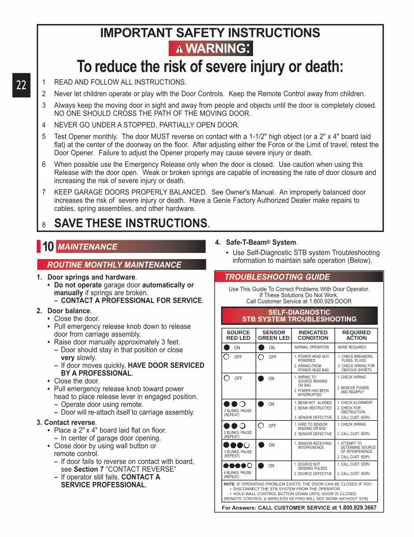
IMPORTANT SAFETY INSTRUCTIONSWARNING:
To reduce the risk of severe injury or death:
MAINTENANCE
1. Door springs and hardware.• Do not operate garage door automatically or
manually if springs are broken. – CONTACT A PROFESSIONAL FOR SERVICE.
2. Door balance.• Close the door.• Pull emergency release knob down to release
door from carriage assembly.• Raise door manually approximately 3 feet.
– Door should stay in that position or close very slowly.
– If door moves quickly, HAVE DOOR SERVICEDBY A PROFESSIONAL.
• Close the door.• Pull emergency release knob toward power
head to place release lever in engaged position. – Operate door using remote.– Door will re-attach itself to carriage assembly.
3. Contact reverse.• Place a 2" x 4" board laid flat on floor.
– In center of garage door opening.• Close door by using wall button or
remote control.– If door fails to reverse on contact with board,
see Section 7 “CONTACT REVERSE”– If operator still fails, CONTACT A
SERVICE PROFESSIONAL.
ROUTINE MONTHLY MAINTENANCE
Use This Guide To Correct Problems With Door Operator. If These Solutions Do Not Work,
Call Customer Service at 1.800.929.DOOR
SELF-DIAGNOSTICSTB SYSTEM TROUBLESHOOTING
SOURCERED LED
SENSORGREEN LED
INDICATEDCONDITION
REQUIREDACTION
ON ON NORMAL OPERATION NONE REQUIRED
OFF OFF 1. POWER HEAD NOTPOWERED
2. WIRING FROM POWER HEAD BAD
1. CHECK BREAKERS, FUSES, PLUGS
2. CHECK WIRING FOR OBVIOUS SHORTS
OFF ON 1. WIRING TO SOURCE MISSING OR BAD
2. POWER HAS BEENINTERRUPTED
1. CHECK WIRING
2. REMOVE POWER AND REAPPLY
2 BLINKS, PAUSE(REPEAT)
ON 1. BEAM NOT ALIGNED2. BEAM OBSTRUCTED
3. SENSOR DEFECTIVE
1. CHECK ALIGNMENT2. CHECK FOR
OBSTRUCTION3. CALL CUST. SERV.
2 BLINKS, PAUSE(REPEAT)
1. WIRE TO SENSOR MISSING OR BAD
2. SENSOR DEFECTIVE
1. CHECK WIRING
2. CALL CUST. SERV.
OFF
3 BLINKS, PAUSE(REPEAT)
ON 1. SENSOR RECEIVING INTERFERENCE
1. ATTEMPT TO DETERMINE SOURCEOF INTERFERENCE
2. CALL CUST. SERV.
4 BLINKS, PAUSE(REPEAT)
ON 1. SOURCE NOTSENDING PULSES
2. SOURCE DEFECTIVE
1. CALL CUST. SERV.
2. CALL CUST. SERV.
NOTE: IF OPERATING PROBLEM EXISTS, THE DOOR CAN BE CLOSED IF YOU:• DISCONNECT THE STB SYSTEM FROM THE OPERATOR• HOLD WALL CONTROL BUTTON DOWN UNTIL DOOR IS CLOSED
(REMOTE CONTROL & WIRELESS KEYPAD WILL NOT WORK WITHOUT STB)
For Answers: CALL CUSTOMER SERVICE at 1.800.929.3667
TROUBLESHOOTING GUIDE
4. Safe-T-Beam® System.• Use Self-Diagnostic STB system Troubleshooting
information to maintain safe operation (Below).
10
1 READ AND FOLLOW ALL INSTRUCTIONS.
2 Never let children operate or play with the Door Controls. Keep the Remote Control away from children.
3 Always keep the moving door in sight and away from people and objects until the door is completely closed.NO ONE SHOULD CROSS THE PATH OF THE MOVING DOOR.
4 NEVER GO UNDER A STOPPED, PARTIALLY OPEN DOOR.
5 Test Opener monthly. The door MUST reverse on contact with a 1-1/2" high object (or a 2" x 4" board laid flat) at the center of the doorway on the floor. After adjusting either the Force or the Limit of travel, retest theDoor Opener. Failure to adjust the Opener properly may cause severe injury or death.
6 When possible use the Emergency Release only when the door is closed. Use caution when using this Release with the door open. Weak or broken springs are capable of increasing the rate of door closure and increasing the risk of severe injury or death.
7 KEEP GARAGE DOORS PROPERLY BALANCED. See Owner's Manual. An improperly balanced door increases the risk of severe injury or death. Have a Genie Factory Authorized Dealer make repairs to cables, spring assemblies, and other hardware.
8 SAVE THESE INSTRUCTIONS.

23
TROUBLESHOOTING GUIDE (CONTINUED) FOR HELP-1.800.929.3667 OR OVERHEADDOOR.COM
• Check lock switch on wall console.• Check power source.
– Plug a lamp into outlet used for power head. If lamp works, power source is OK.
– If not, check fuse or circuit breaker.• Power is OK.
– Check connections at power head terminals.
– Check connections at wall control.• Check wires to ensure they are not cut.
Staples can cut insulation and short wires. If wire is cut, replace it.
• Was a remote control lost or stolen? Erase all remote control codes from receiver memory and reprogram (See section ).
• Button stuck on wall control.• Check CLOSE limit switch setting
(See section ).• Wires shorted.
• Check CONTACT REVERSE(See section ).
• Check “STB” system for beam obstruction or misalignment of lenses (See section ).
• Check “STB” diagnostic code.• Check “CLOSE FORCE” adjustment
(See section ).
• Check OPEN limit switch for short and proper wiring.
• Check “OPEN FORCE” adjustment(See section ).
• Check door condition and door spring.
• Check “STB” system (See self-diagnostic STB Troubleshooting Chart).
• Check CLOSE limit switch for short and proper wiring.
• Check “CLOSE FORCE” adjustment (See section ).
• Disconnect and reconnect wires on wall control(See section ).
• Check wiring.• Incompatible wall control.
4
6
6
6
3
6
6
7
Use wall control supplied with operator. Any other wall control can causethe operator to operate unexpectedly and light not to work.
CAUTION
Door starts down,then stops beforeit’s closed.
• Be sure door, operator, and springs are in good repair, properly lubricated and balanced (See maintenance section).
• Check “OPEN” limit switch setting (See section ).
• Check “OPEN FORCE” adjustment (See section ).
• Make sure carriage is engaged to carriage slide.– place carriage lever in lock position.
• Check force adjustment (See section ).Door operator will NOT run more than 30 seconds each way if door does not move.
• Relocate remote control inside car.• Point remote control at garage door.• Replace battery (See section ).• Reposition door operator antenna.• DO NOT attempt to retune remote controls.
• Program remote control code into receiver memory. (See section ).
• Replace remote control battery with good one. (See section ).
• Be sure all fasteners are tight.• Be sure door and operator is in good repair,
properly lubricated and balanced (See monthly maintenance section).
If an operational problem exists, and operatorwill not run closed. The operator can be forcedto close as shown below (See section ).• Disconnect the “STB” system from the
operator.• Hold the wall control button down until door is
completely closed.
Use self-diagnostic “STB” system Troubleshootinginformation to maintain safe operation.
5
8
7
8
6
6
6
Door starts up,but stops beforeit’s completelyopen.
Door will onlyrun closed.
Door operatorstarts for no reason.
Operator does not run from wall control
Door startsdown, then stopsand goes back up.
Lights will not goout.
Door will onlyrun open.
Remote controlhas less than 25feet operatingrange.
Operator runs,but door doesnot move.
Safe-T-Beam®
systemmalfunction.
Noisy operation.
Operator worksfrom wall control, but not from remote control.
If you have any questions, please do not hesitate tocontact customer service at:
1.800.929.3667

24
WIRING DIAGRAM FOR HELP-1.800.929.3667 OR OVERHEADDOOR.COMST
B Br
acke
t Ext
ensi
ons
-Pro
vides
add
itiona
l bra
cket
leng
th w
here
it m
ay b
e ne
eded
for c
leara
nce.

25
INSTALLATION NOTES FOR HELP-1.800.929.3667 OR OVERHEADDOOR.COM
Transmitters comply with all United States and Canadian legal requirements as of the date of manufacture. No warranty is madethat they comply with all legal requirements of any other jurisdiction. If transmitters are to be used in another country, the importermust determine compliance with any local laws and regulations which may differ from United States and Canadian requirementsprior to use.
Los transmisores cumplen con todas las reglamentaciones legales de los Estados Unidos y del Canadá, en la fecha de fabricación.Ninguna garantía se da que cumplan con todas las reglamentaciones legales de ninguna otra jurisdicción. Si los transmisores sevan a utilizar en otro país, el importador debe determinar si cumplen con las reglamentaciones y leyes locales que puedan serdiferentes a las reglamentaciones de los Estados Unidos y del Canadá, antes de usar los mismos.
Les émetteurs sont conformes à la réglementation américaine et canadienne à compter de leur date de fabrication. Aucune garantien’est stipulée indiquant qu’ils sont conformes à toutes les prescriptions juridiques d’autres autorités. Si les émetteurs sont utilisésdans d’autres pays, il incombe à l’importateur d’en déterminer leur conformité aux lois et règles locales pouvant différer de cellesdes États-Unis et du Canada avant toute utilisation desdits émetteurs.
Sendegeräte entsprechen allen gesetzlichen Bestimmungen in den USA und Kanada zum Zeitpunkt der Herstellung. Wirübernehmen keine Gewährleistung für die Einhaltung aller gesetzlichen Bestimmungen in anderen Ländern. Sollen Sendegeräte inanderen Ländern eingesetzt werden, so muss der Importeur vor dem Gebrauch sicherstellen, dass die Sendegeräte auch solchenlokalen Bestimmungen entsprechen, welche von den Bestimmungen der USA und Kanadas abweichen.
TRANSMITTER COMPLIANCE STATEMENT

26
SAVE THESE INSTRUCTIONS
Visit Our Website at: www.overheaddoor.com
Manufactured under one or more of the following U.S. patents:3,898,582 4,041,259 4,048,6304,064,487 4,103,238 5,222,403
Other Patents applied for.
CORRESPONDENCE WITH FACTORYMUST INCLUDE DATE / MFG. NO.
(LOCATED UNDER LENS OF POWER HEAD)
FILL THIS IN AT TIME OF INSTALLATION FOR YOUR OWN RECORDS, SO THAT IT WILLBE AVAILABLE IF YOU EVER NEED TO CALL US.
Date Purchased _____/_____/_____ Date/Mfg. No. _____/_____/______ Serial Number__________________________________________________________________________Operator Model _________________________________________________________________________Remote Control Model____________________________________________________________________Dealer Name ____________________________________________________________________________Dealer Address _________________________________________________________________________City ___________________________________________________________________________________State __________________________________________________________________________________Zip _____________________
WK YR PIMO D YR
Overhead Door Corporation (“ODC”) warrants to the originalpurchaser of the garage door operator as follows:
Model OCG600ML - Motor 5 years and all other parts 3 years.Model OCG800ML -Motor Lifetime* and all other parts 3 years.
*Lifetime warranty -warranted for as long as you own your home.
ODC’s obligation under this warranty is specifically limited torepairing or replacing at its option, any parts which shall bedetermined by ODC to be defective during the applicablewarranty period. This warranty applies only to the original purchaser and is not transferable.
Repair or replacement labor is included for a period of oneyear from the date of installation. After one year, all laborcharges will be the responsibility of the owner. This warrantyapplies only to the original purchaser and is not transferable.
This warranty does not apply to any operator installed in acommercial, industrial, or other non-residential application.This warranty does not apply to any operator which has beenaltered or repaired by any person not expressly authorized byODC in writing to do so. This warranty does not apply to anyboom or part which has been damaged or deteriorated due tomisuse, accident, or failure to provide necessary maintenance,fire, flood or acts of God.
Limited WarrantyTHERE IS NO WARRANTY OF MERCHANTABILITY, WARRANTY OF FITNESS FOR ANY PARTICULAR PURPOSE OR ANY OTHER IMPLIED WARRANTYBEYOND ONE YEAR FROM THE DATE OF INSTALLATION.ODC SHALL NOT BE LIABLE FOR INCIDENTAL ORCONSEQUENTIAL DAMAGES NOR FOR ANY FURTHERLOSS WHICH MAY ARISE IN CONNECTION WITH ANY CLAIM.
This warranty gives you specific legal rights, and you mayalso have other rights which vary from state to state. Somestates do not allow limitations on how long an implied warranty lasts and some states do not allow the exclusion orlimitation of incidental or consequential damages, so theabove limitations or exclusions may not apply to you.
ODC has not established any informal dispute settlement procedure of the type described in the Magnuson-MossWarranty Act. Claims under this warranty must be made inwriting to ODC or one of its authorized distributors within theapplicable warranty period. Either the original seller may becontacted or the nearest Overhead Door Distributor may becontacted by calling 1-800-929-DOOR (1.800.929.3667).(Proof of purchase and identification as the original purchasermay be required.)

AUniversal Wall ButtonBotón de pared universalBouton mural universel
Wireless Keypad Entry SystemSistema de entrada por teclado numérico inalámbricoSystème d’ouvre-porte de garage à clavier sans fil
Universal Conversion KitJuego de conversión universalNécessaire de conversion universel
60 WATT Light BulbBombilla de 60 VatiosÉclairage de 60 WATT
Emergency Release KitJuego de pica-porte de pestilloNécessaires de d’clenchement de secours
Garage Door Operator AccessoriesAccesorios para abridores de puertas de garajeAccessoires pour ouvre-porte de garage
1-Button Remote Control with CodeDodgerControlador remoto de lujo con CodeDodgerTélécommande de luxe avec CodeDodger
2-Button Remote Control with CodeDodgerControlador remoto de 2 funciones con CodeDodgerTélécommande à 2 fonctions avec CodeDodger
3-Button Remote Control with CodeDodgerControlador remoto de 3 funciones con CodeDodgerTélécommande à 3 fonctions avec CodeDodger
3-Button Mini Remote Control with CodeDodgerMinicontrolador remoto de 3 botón con CodeDodgerMini télécommande à 3 bouton avec CodeDodger
3-Function Wall Console with CodeDodgerConsola de pared de 3 funciones con CodeDodgerConsole murale à trois fonctions avec CodeDodger
OverHead Door CorporationAccess Systems Division22790 Lake Park Blvd.Alliance, Ohio 44601
3DEFDEF
1 2
4 5 6
7 8 9
0
GHIGHI JKLJKL MNOMNO
PQRSPQRS TUVTUV WXYZWXYZ
9V9V
Call: 1.800.929.3667Web: www.overheaddoor.com

OverHead Door CorporationAccess Systems Division22790 Lake Park Blvd.Alliance, Ohio 44601
Call: 1.800.929.3667Web: www.overheaddoor.com