
Ocula 1.0 Nuke
75
USER GUIDE Ocula on Nuke Visual Effects Software The Foundry
Transcript of Ocula 1.0 Nuke

USER GUIDE
Tind
Ocula on Nuke
er Box1 The Foundry
Visual Effects Software The Foundry

©2008 The Foundry Visionmongers Ltd. All rights reserved.Ocula 1.0 User GuideThis manual, as well as the software described in it, is furnished under license and may only be used or copied in accordance with the terms of such license. This manual is provided for informational use only and is subject to change without notice. The Foundry assumes no responsibility or liability for any errors of inaccuracies that may appear in this book.
No part of this manual may be reproduced, stored in a retrieval system, or transmitted in any form without the prior written permission of The Foundry.
The Foundry logo is a trademark of The Foundry Visionmongers Ltd. Nuke is a registered trademark of The Foundry Visionmongers Ltd. All other products or brands are trademarks or registered trademarks of their respective companies or organisations.
Software engineering Ben Kent, Abigail Brady, Bruno Nicoletti, Simon Robinson, Lucy Hallpike.
Product testing Sean Brice, Ben Minall.
Writing and layout design Eija Närvänen using Adobe FrameMaker.
Proof reading Eija Närvänen.
The Foundry Tinder Box1
iii
Contents
Introduction About this User Guide. . . . . . . . . . . . . . . . . . . . . . . . . . . . . . 5
What’s New? . . . . . . . . . . . . . . . . . . . . . . . . . . . . . . . . . . . . . 5
Example Images . . . . . . . . . . . . . . . . . . . . . . . . . . . . . . . . . . 5
System Requirements . . . . . . . . . . . . . . . . . . . . . . . . . . . . . . 6
Installation . . . . . . . . . . . . . . . . . . . . . . . . . . . . . . . . . . . . . . 6
Install Directory . . . . . . . . . . . . . . . . . . . . . . . . . . . . . . . . . . 7
Generic Install Directory . . . . . . . . . . . . . . . . . . . . . . . . . . . . 8
Moving the Plug-ins Directory . . . . . . . . . . . . . . . . . . . . . . . 8
Licensing Ocula . . . . . . . . . . . . . . . . . . . . . . . . . . . . . . . . . . . 8
Other Foundry Products . . . . . . . . . . . . . . . . . . . . . . . . . . . . 9
Ocula Plug-ins DisparityGenerator . . . . . . . . . . . . . . . . . . . . . . . . . . . . . . . 11
ColourMatch . . . . . . . . . . . . . . . . . . . . . . . . . . . . . . . . . . . . 23
Correlate . . . . . . . . . . . . . . . . . . . . . . . . . . . . . . . . . . . . . . . 28
InterocularShifter . . . . . . . . . . . . . . . . . . . . . . . . . . . . . . . . 38
NewView . . . . . . . . . . . . . . . . . . . . . . . . . . . . . . . . . . . . . . . 45
VerticalAligner . . . . . . . . . . . . . . . . . . . . . . . . . . . . . . . . . . 55
Appendix A Release Notes . . . . . . . . . . . . . . . . . . . . . . . . . . . . . . . . . . . 65
Appendix B End User License Agreement . . . . . . . . . . . . . . . . . . . . . . . 67
Index A-Z . . . . . . . . . . . . . . . . . . . . . . . . . . . . . . . . . . . . . . . . . . . 75
The Foundry Ocula 1.0

iv
Ocula 1.0 The Foundry
About this User Guide
INTRODUCTION 5
INTRODUCTION
Welcome to this User Guide for Ocula 1.0 on Nuke. Ocula is a collection of tools that solve common problems with stereoscopic imagery, improve productivity in post production, and ultimately help to deliver a more rewarding 3D-stereo viewing experience.
All Ocula plug-ins integrate seamlessly into Nuke. They are applied to your clips as any other node and they can all be animated using the standard Nuke animation tools.
About this User Guide
This User Guide will tell you how to install, license, and use the Ocula 1.0 plug-ins and tools. Each plug-in or tool is described in detail in later chapters.
This guide assumes you are familiar with Nuke and the machine it is running on.
What’s New? To read about the new features, improvements and fixed bugs in this release, see “Release Notes” on page 65 of Appendix A.
Example Images Example images are provided for use with all of the plug-ins. You can download these images from our web site at http://www.thefoundry.co.uk and try Ocula out on them. From the main page, go to PLUG-INS > for Nuke > Ocula, then click on the Tutorials & Example Images link on the right hand side.
The Foundry Ocula 1.0
INTRODUCTION6System Requirements
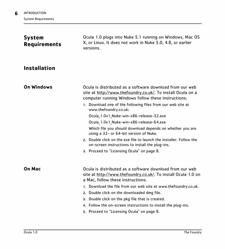
System Requirements
Ocula 1.0 plugs into Nuke 5.1 running on Windows, Mac OS X, or Linux. It does not work in Nuke 5.0, 4.8, or earlier versions.
Installation
On Windows Ocula is distributed as a software download from our web site at http://www.thefoundry.co.uk/. To install Ocula on a computer running Windows follow these instructions:
1. Download one of the following files from our web site at www.thefoundry.co.uk:
Ocula_1.0v1_Nuke-win-x86-release-32.exe
Ocula_1.0v1_Nuke-win-x86-release-64.exe
Which file you should download depends on whether you are using a 32- or 64-bit version of Nuke.
2. Double click on the exe file to launch the installer. Follow the on-screen instructions to install the plug-ins.
3. Proceed to “Licensing Ocula” on page 8.
On Mac Ocula is distributed as a software download from our web site at http://www.thefoundry.co.uk/. To install Ocula 1.0 on a Mac, follow these instructions:
1. Download the file from our web site at www.thefoundry.co.uk.
2. Double click on the downloaded dmg file.
3. Double click on the pkg file that is created.
4. Follow the on-screen instructions to install the plug-ins.
5. Proceed to “Licensing Ocula” on page 8.
Ocula 1.0 The Foundry
Install Directory
INTRODUCTION 7
On Linux Ocula is distributed as a software download from our web site at http://www.thefoundry.co.uk/. To install Ocula 1.0 on a computer running Linux, follow these instructions:
1. Download one of the following files from our web site at www.thefoundry.co.uk:
Ocula_1.0v1_Nuke-linux-x86-release-32.tgz
Ocula_1.0v1_Nuke-linux-x86-release-64.tgz
Which file you should download depends on whether you are using a 32- or 64-bit version of Nuke.
2. Move the downloaded file to the following directory (create the directory if it does not yet exist):
/usr/OFX/
3. In the above mentioned directory, extract the files from the archive using one of the following commands. This will create a Nuke subdirectory (if one doesn’t already exist) and install the plug-ins in that directory.
tar xvzf Ocula_1.0v1_Nuke-linux-x86-release-32.tgz
tar xvzf Ocula_1.0v1_Nuke-linux-x86-release-64.tgz
Which command you use depends on which file you downloaded from our web site.
4. Proceed to “Licensing Ocula” on page 8.
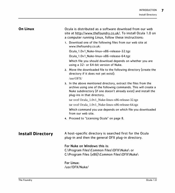
Install Directory A host-specific directory is searched first for the Ocula plug-in and then the general OFX plug-in directory.
For Nuke on Windows this is:C:\Program Files\Common Files\OFX\Nuke\ orC:\Program Files (x86)\Common Files\OFX\Nuke\
For Linux:/usr/OFX/Nuke/
The Foundry Ocula 1.0
INTRODUCTION8Generic Install Directory
For Mac OS X:/Library/OFX/Nuke/
Generic Install Directory
After looking in the host-specific directory for an Ocula plug-in, we search in the generic OFX plug-in directory as follows.
For Windows:C:\Program Files\Common Files\OFX\Plugins\ or C:\Program Files (x86)\Common Files\OFX\Plugins\
For Linux:/usr/OFX/Plugins/
For Mac OS X:/Library/OFX/Plugins/
Moving the Plug-ins Directory
You can put the OFX plug-ins anywhere as long as you set the environment variable OFX_PLUGIN_PATH to point to it.
Licensing Ocula Without a license key, the Ocula plug-ins will fail to run.
The license key is a sequence of numbers and letters, stored in a plain text file, that unlocks Ocula. License keys can be created for a particular computer enabling those plug-ins to run only on that computer. These are called node locked licenses. We also supply floating licenses that will unlock Ocula on any networked computer connected to a machine running the Foundry license server.
Ocula 1.0 The Foundry
Other Foundry Products
INTRODUCTION 9
Tools to install license keys, manage floating licenses, and diagnose license problems can be downloaded from our web site, http://www.thefoundry.co.uk/licensing.
Other Foundry Products
The Foundry is a leading developer of visual effects software for film and video post production. Its products include Nuke, Furnace, Tinder, Tinderbox, and Keylight and run on a variety of compositing platforms including Discreet Flame from Autodesk, Avid DS and Apple’s Shake. For the full list of products and supported platforms see http://www.thefoundry.co.uk.
Nuke is an Academy Award® winning compositor. It has been used to create extraordinary images on scores of feature films including The Dark Knight, The Golden Compass, Iron Man, Transformers, King Kong, and Pirates of the Caribbean: At World’s End.
Furnace is a collection of film tools. Many of the algorithms utilize motion estimation technology to speed up common compositing tasks. Plug-ins include wire removal, rig removal, steadiness, deflicker, degrain and regrain, retiming, and texture tools.
Tinder and Tinderbox are collections of image processing effects including blurs, distortion effects, background generators, colour tools, wipes, matte tools, painterly effects, lens flares and much more.
Keylight is an Academy Award winning blue/green screen keyer giving results that look photographed not composited. The Keylight algorithm was developed by the Computer Film
The Foundry Ocula 1.0
INTRODUCTION10Other Foundry Products
Company who were honoured with a technical achievement award for digital compositing from the Academy of Motion Picture Arts and Sciences.
Visit The Foundry’s web site at http://www.thefoundry.co.uk for further details.
Ocula 1.0 The Foundry
DisparityGenerator
OCULA PLUG-INS 11
OCULA PLUG-INS
DisparityGenerator
Description The O_DisparityGenerator is used to create disparity fields for stereo images. A disparity field maps the location of a pixel in one view to the location of its corresponding pixel in the other view. It includes two sets of disparity vectors: one maps the left view to the right, and the other maps the right view to the left.
Most Ocula plug-ins rely on disparity fields to produce their output. If you have more than one Ocula plug-in in your node tree with one or more of the same inputs, they might well require identical disparity field calculations. O_DisparityGenerator is a utility plug-in designed to save processing time by allowing you to create the disparity fields separately, so that the results can then be reused by other Ocula plug-ins.
In general, once you have generated a disparity field that describes the relation between the views of a particular clip well, it will be suitable for use in most of the Ocula plug-ins. We recommend that you insert a Write node after O_DisparityGenerator to render the original images and the disparity channels as an .exr file. This format allows for the storage of an image with multiple views and channel sets embedded in it. Later, whenever you use the same image sequence, the disparity field will be loaded into Nuke together with the sequence and is readily available for the Ocula plug-ins. For information on how to generate a
The Foundry Ocula 1.0
OCULA PLUG-INS12DisparityGenerator
disparity field and render it as an .exr file, see page 13.
Generating a Disparity Field
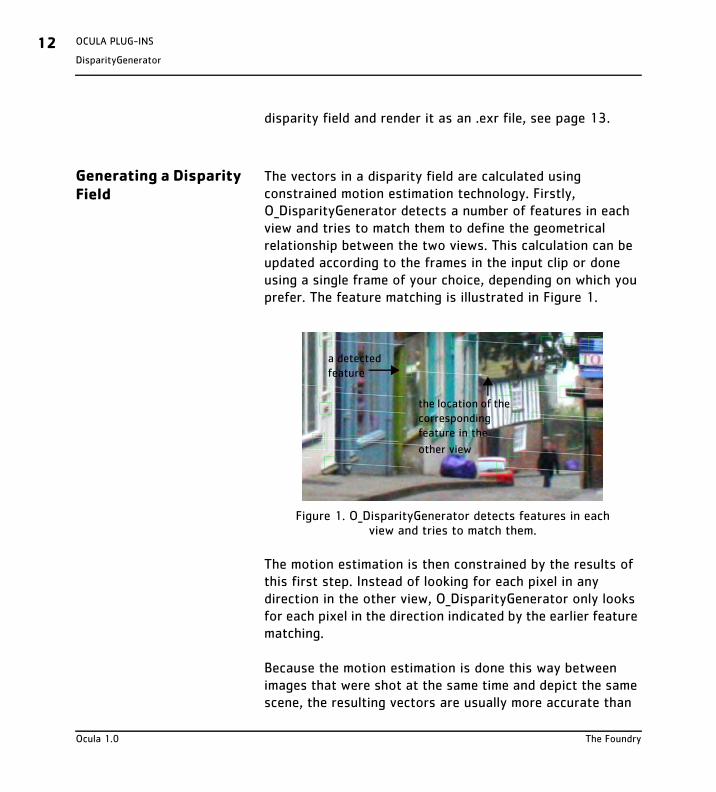
The vectors in a disparity field are calculated using constrained motion estimation technology. Firstly, O_DisparityGenerator detects a number of features in each view and tries to match them to define the geometrical relationship between the two views. This calculation can be updated according to the frames in the input clip or done using a single frame of your choice, depending on which you prefer. The feature matching is illustrated in Figure 1.
The motion estimation is then constrained by the results of this first step. Instead of looking for each pixel in any direction in the other view, O_DisparityGenerator only looks for each pixel in the direction indicated by the earlier feature matching.
Because the motion estimation is done this way between images that were shot at the same time and depict the same scene, the resulting vectors are usually more accurate than
Figure 1. O_DisparityGenerator detects features in each view and tries to match them.
a detected feature
the location of the corresponding feature in the
other view
Ocula 1.0 The Foundry
DisparityGenerator
OCULA PLUG-INS 13
motion vectors created using two frames of an image sequence.
The final disparity vectors are stored in disparity channels, so you might not see any image data appear when you first calculate the disparity field. If you want to see the output inside Nuke, you need to select the disparity channels from the channel set and channel controls in the top left corner of the Viewer. An example of what a disparity channel might look like is shown on page 22.
Quick Start To generate a disparity field for a stereo clip, do the following:
1. Start Nuke and press S on the Node Graph to open the project settings. Go to the Views tab and click the Set up views for ste-reo button.
2. From the Toolbar, select Image > Read to load your stereo clip into Nuke. If you don’t have both views in the same file, select Views > JoinViews to combine them, or use a variable in the Read node’s file field to replace the name of the view (use the variable %V to replace and entire view name, such as left or right, and %v to replace an initial letter, such as l or r). For more information, refer to the Nuke user guide.
3. Select Ocula > O_DisparityGenerator to insert an O_DisparityGenerator node after either the stereo clip or the JoinViews node (if you inserted one in the previous step).
The Foundry Ocula 1.0
OCULA PLUG-INS14DisparityGenerator
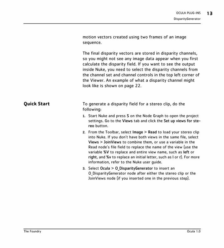
4. Open the O_DisparityGenerator controls. From the Views to Use menu or buttons, select which views you want to use for the left and right eye when creating the disparity field.
5. Attach a Viewer to the O_DisparityGenerator node, and display one of the disparity channels in the Viewer.
O_DisparityGenerator calculates the disparity field and stores it in the disparity channels.
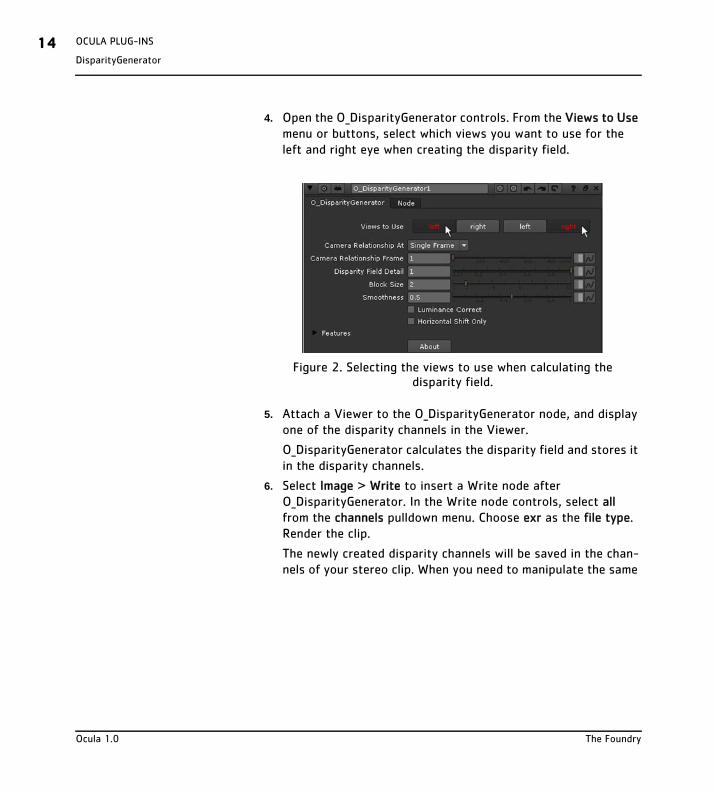
6. Select Image > Write to insert a Write node after O_DisparityGenerator. In the Write node controls, select all from the channels pulldown menu. Choose exr as the file type. Render the clip.
The newly created disparity channels will be saved in the chan-nels of your stereo clip. When you need to manipulate the same
Figure 2. Selecting the views to use when calculating the disparity field.
Ocula 1.0 The Foundry
DisparityGenerator
OCULA PLUG-INS 15
clip again later, the disparity vectors will be loaded into Nuke together with the clip.
7. If the calculated disparity field does not produce the results you’re after, use the O_DisparityGenerator controls to adjust the way the disparity field is calculated. The available controls are described below.
Controls Views to Use - From the views that exist in your project settings, select the two views you want to use to create the disparity field. These views will be mapped for the left and right eye.
Camera Relationship At - Select how to search for matching features in each view to calculate the relationship between the views. Defining this relationship is the first step in the process of creating a disparity map.
• Specified Frame - The feature matching is done using a single frame from the source clip. You can specify this
Figure 3. Rendering the output to combine the clip and the disparity channels for future use.
The Foundry Ocula 1.0
OCULA PLUG-INS16DisparityGenerator
frame using the Camera Relationship Frame parameter below.
• Current Frame - The feature matching is calculated so that it updates according to the frames in the source clip. This is the default.
Camera Relationship Frame - The frame the feature matching is done on. This parameter is only available if you have set Camera Relationship At to Specified Frame.
Disparity Field Detail - Adjust this to vary the resolution of the images used to calculate the disparity field. The larger the value, the greater the processing time, but the more detailed the vectors. The default value of 1.0 will generate a vector at each pixel. A value of 0.5 will generate a vector at every other pixel.
Block Size - This defines the width and height (in pixels) of the square blocks used to generate the disparity vectors. Smaller values will produce noisy data, larger values miss detail. This value should rarely need editing, but some sequences may benefit from using large block sizes to help the algorithm track regions better where the algorithm isn’t ’locking on’ to the overall disparity in the sequence.
Smoothness - Set the smoothness weighting of the disparity calculation. Disparity fields usually have two important qualities: they should accurately match similar pixels in one image to another and they should be smooth rather than noisy. Often, it is necessary to trade one of these qualities off against the other. A high smoothness will miss lots of local detail, but is less likely to provide you with the odd spurious vector. A low smoothness will concentrate on detail matching, even if the resulting field is jagged. The default
Ocula 1.0 The Foundry
DisparityGenerator
OCULA PLUG-INS 17
value of 0.5 should work well for most sequences.
Luminance Correct - For clips where there is a global luminance shift between views, toggling this control on will allow O_DisparityGenerator to take account of overall brightness changes between views and should improve the disparity estimation.
Horizontal Shift Only - If the disparity between your stereo views is horizontal only (corresponding pixels lie on the same scanline in both images), you can check this for faster processing.
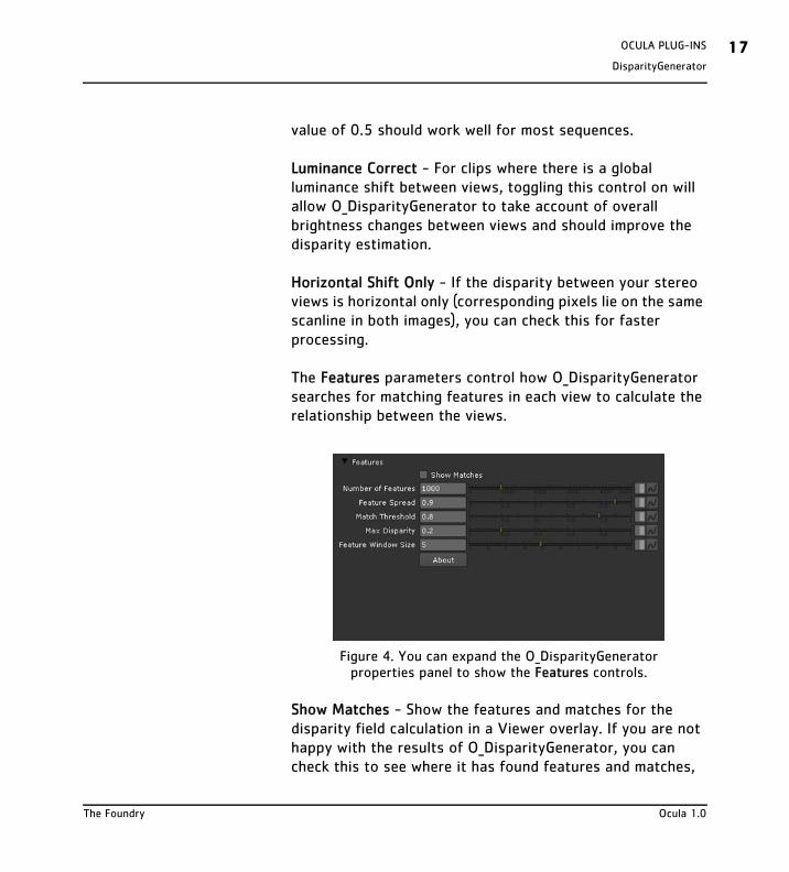
The Features parameters control how O_DisparityGenerator searches for matching features in each view to calculate the relationship between the views.
Show Matches - Show the features and matches for the disparity field calculation in a Viewer overlay. If you are not happy with the results of O_DisparityGenerator, you can check this to see where it has found features and matches,
Figure 4. You can expand the O_DisparityGenerator properties panel to show the Features controls.
The Foundry Ocula 1.0
OCULA PLUG-INS18DisparityGenerator
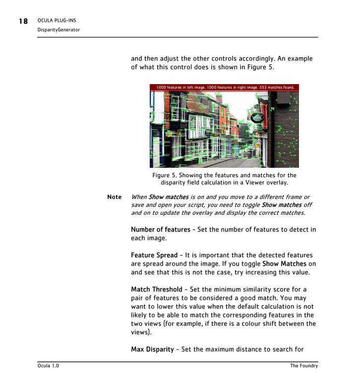
and then adjust the other controls accordingly. An example of what this control does is shown in Figure 5.
Note When Show matches is on and you move to a different frame or save and open your script, you need to toggle Show matches off and on to update the overlay and display the correct matches.
Number of features - Set the number of features to detect in each image.
Feature Spread - It is important that the detected features are spread around the image. If you toggle Show Matches on and see that this is not the case, try increasing this value.
Match Threshold - Set the minimum similarity score for a pair of features to be considered a good match. You may want to lower this value when the default calculation is not likely to be able to match the corresponding features in the two views (for example, if there is a colour shift between the views).
Max Disparity - Set the maximum distance to search for
Figure 5. Showing the features and matches for the disparity field calculation in a Viewer overlay.
Ocula 1.0 The Foundry
DisparityGenerator
OCULA PLUG-INS 19
matches, as a fraction of the image width. If the corresponding features in your images are far apart and you get poor results with the default settings, you may want to increase this value.
Feature Window Size - Set the width and height (in pixels) of the square window O_DisparityGenerator tries to match around each feature. Note that for the feature detection, the image is temporarily converted into the PAL format (720x576) or close, depending on the pixel aspect ratio.
About - Show information about this plug-in. The information includes the plug-in’s version number and help text as well as the location of this user guide. You can also click the ? button on the O_DisparityGenerator properties panel to display the same information.
Example In this example, we read in a stereo image, calculate its disparity field, and render the result as an .exr file that contains the left and the right view and the newly created disparity channels. The stereo image used here can be downloaded from our web site. For more information, please see “Example Images” on page 5.
Step by Step
1. Start Nuke and press S on the Node Graph to open the project settings. Go to the Views tab and click the Set up views for ste-reo button.
2. Import forest_left.tif. In the Read node controls, locate the file field. Then, replace the word left in the file name with the variable %V. This way, Nuke reads in both the left and the right view using the same Read node.
The Foundry Ocula 1.0
OCULA PLUG-INS20DisparityGenerator
3. Select the Read node and choose Ocula > O_DisparityGenerator from the Toolbar. This inserts an O_DisparityGenerator node after the stereo image.
4. Attach a Viewer to the O_DisparityGenerator node, and display one of the disparity channels. O_DisparityGenerator calculates the disparity field.
Note that in the forest image a lot of the trees in the left view are not visible in the right. Images like this (where elements in one view are occluded in the other) can be tricky from the point of view of disparity estimation. When used with some of the other Ocula plug-ins, such as O_NewView, the results may need further editing.
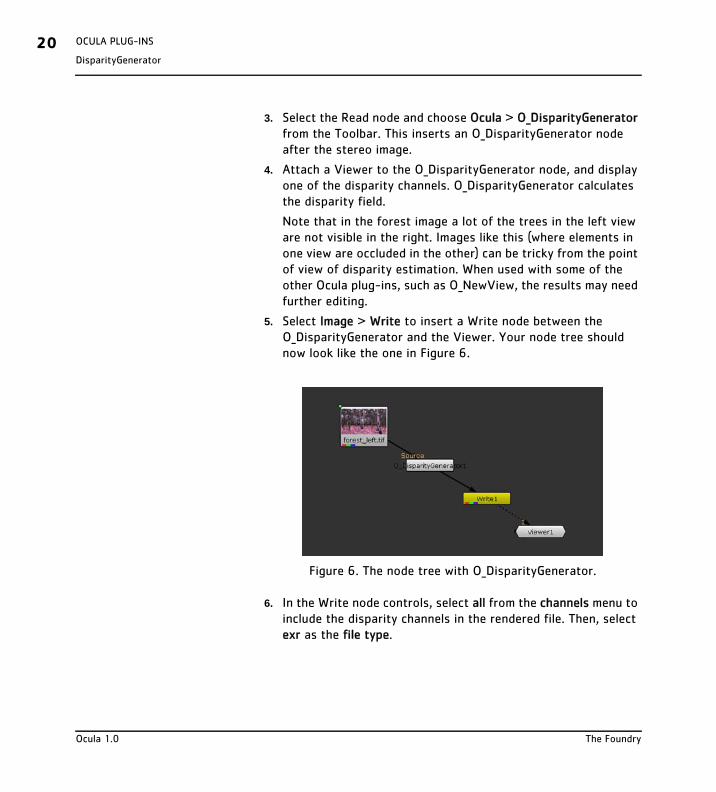
5. Select Image > Write to insert a Write node between the O_DisparityGenerator and the Viewer. Your node tree should now look like the one in Figure 6.
6. In the Write node controls, select all from the channels menu to include the disparity channels in the rendered file. Then, select exr as the file type.
Figure 6. The node tree with O_DisparityGenerator.
Ocula 1.0 The Foundry
DisparityGenerator
OCULA PLUG-INS 21
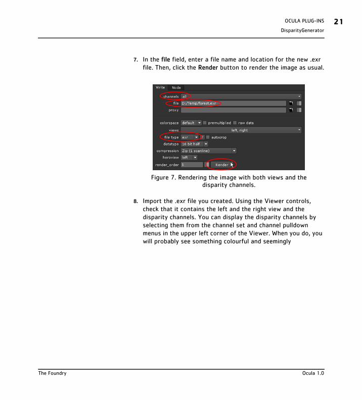
7. In the file field, enter a file name and location for the new .exr file. Then, click the Render button to render the image as usual.
8. Import the .exr file you created. Using the Viewer controls, check that it contains the left and the right view and the disparity channels. You can display the disparity channels by selecting them from the channel set and channel pulldown menus in the upper left corner of the Viewer. When you do, you will probably see something colourful and seemingly
Figure 7. Rendering the image with both views and the disparity channels.
The Foundry Ocula 1.0
OCULA PLUG-INS22DisparityGenerator
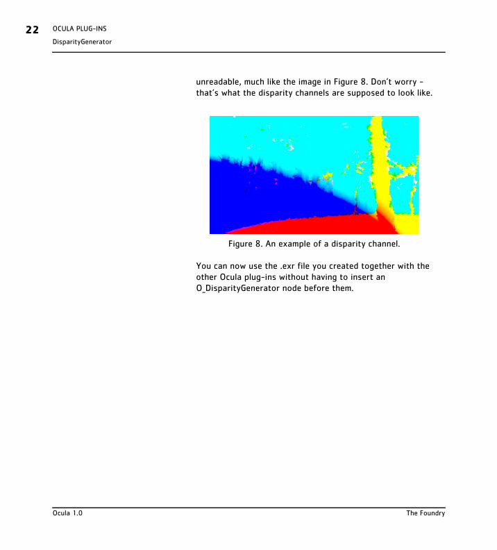
unreadable, much like the image in Figure 8. Don’t worry - that’s what the disparity channels are supposed to look like.
You can now use the .exr file you created together with the other Ocula plug-ins without having to insert an O_DisparityGenerator node before them.
Figure 8. An example of a disparity channel.
Ocula 1.0 The Foundry
ColourMatch
OCULA PLUG-INS 23
ColourMatch
Description The O_ColourMatch plug-in lets you match the colours of one view with those of another. It has been specifically designed to deal with the subtle colour differences that are sometimes present between stereo views.
Colour discrepancies between views can be caused by several factors. For example, stereo footage may have been shot with cameras which were differently polarised, or there may have been slight differences between the physical characteristics of the two camera lenses or image sensors. If the colour differences are not corrected for, viewers of the footage may find it difficult to fuse objects in the scene and enjoy the viewing experience.
Correcting for colour differences manually in post production tends to be a time-consuming process and requires considerable skill. Using O_ColourMatch, however, you can automate the colour grading required. O_ColourMatch does the work for you by modifying the colour histogram of one view to match that of the other. You may find that the plug-in works better with subtle colour differencies than cases of extreme colour discrepancy.
This plug-in differs from most of the Ocula plug-ins in that it does not need disparity vectors. This is because O_ColourMatch does not use any spatial information but tries to match the overall colour distribution of one view to that of the other. You do not need to use the O_DisparityGenerator with O_ColourMatch.
The Foundry Ocula 1.0
OCULA PLUG-INS24ColourMatch
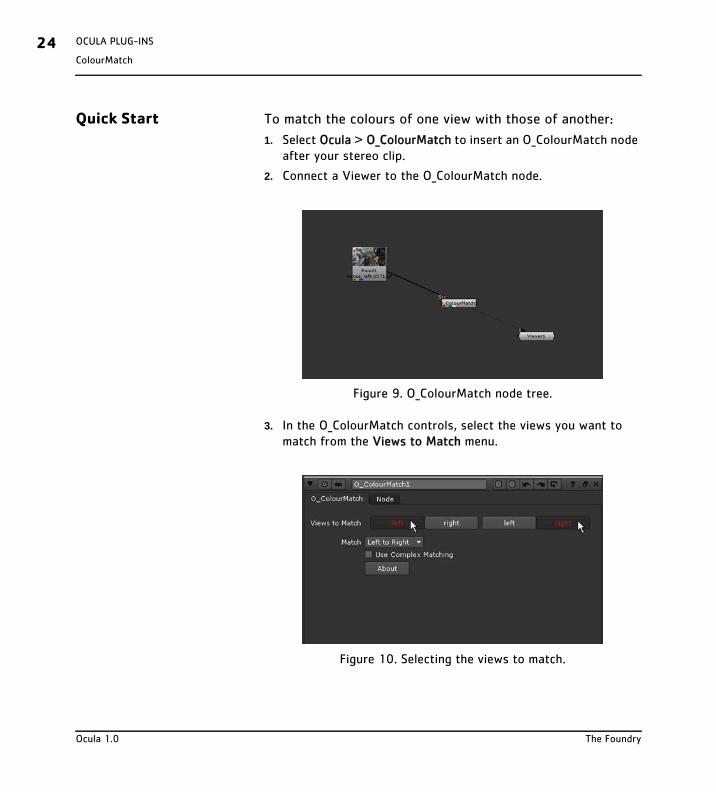
Quick Start To match the colours of one view with those of another:
1. Select Ocula > O_ColourMatch to insert an O_ColourMatch node after your stereo clip.
2. Connect a Viewer to the O_ColourMatch node.
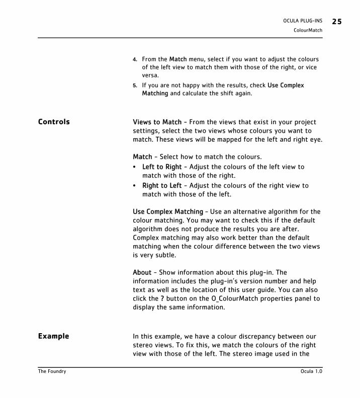
3. In the O_ColourMatch controls, select the views you want to match from the Views to Match menu.
Figure 9. O_ColourMatch node tree.
Figure 10. Selecting the views to match.
Ocula 1.0 The Foundry
ColourMatch
OCULA PLUG-INS 25
4. From the Match menu, select if you want to adjust the colours of the left view to match them with those of the right, or vice versa.
5. If you are not happy with the results, check Use Complex Matching and calculate the shift again.
Controls Views to Match - From the views that exist in your project settings, select the two views whose colours you want to match. These views will be mapped for the left and right eye.
Match - Select how to match the colours.
• Left to Right - Adjust the colours of the left view to match with those of the right.
• Right to Left - Adjust the colours of the right view to match with those of the left.
Use Complex Matching - Use an alternative algorithm for the colour matching. You may want to check this if the default algorithm does not produce the results you are after. Complex matching may also work better than the default matching when the colour difference between the two views is very subtle.
About - Show information about this plug-in. The information includes the plug-in’s version number and help text as well as the location of this user guide. You can also click the ? button on the O_ColourMatch properties panel to display the same information.
Example In this example, we have a colour discrepancy between our stereo views. To fix this, we match the colours of the right view with those of the left. The stereo image used in the
The Foundry Ocula 1.0
OCULA PLUG-INS26ColourMatch
example can be downloaded from our web site. For more information, please see “Example Images” on page 5.
Step by Step
1. Start Nuke and open the project settings by pressing S on the Node Graph. Go to the Views tab and click the Set up views for stereo button.
2. Import dance.exr. This image already includes both the left and the right view. Because O_ColourMatch does not need disparity vectors, you do not need to insert an O_DisparityGenerator node into your script.
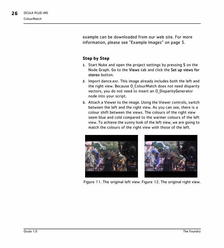
3. Attach a Viewer to the image. Using the Viewer controls, switch between the left and the right view. As you can see, there is a colour shift between the views. The colours of the right view seem blue and cold compared to the warmer colours of the left view. To achieve the sunny look of the left view, we are going to match the colours of the right view with those of the left.
Figure 11. The original left view. Figure 12. The original right view.
Ocula 1.0 The Foundry
ColourMatch
OCULA PLUG-INS 27
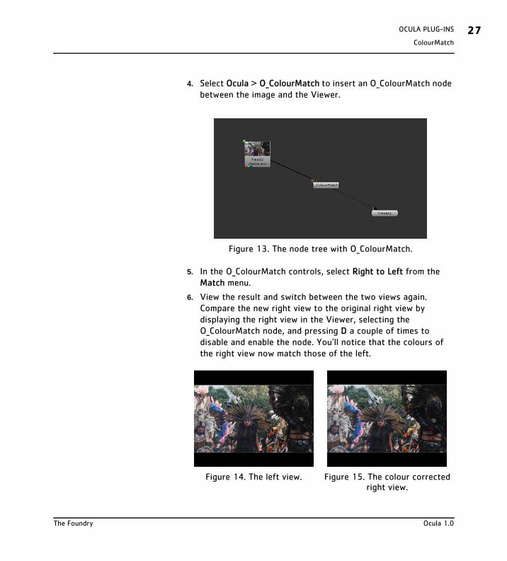
4. Select Ocula > O_ColourMatch to insert an O_ColourMatch node between the image and the Viewer.
5. In the O_ColourMatch controls, select Right to Left from the Match menu.
6. View the result and switch between the two views again. Compare the new right view to the original right view by displaying the right view in the Viewer, selecting the O_ColourMatch node, and pressing D a couple of times to disable and enable the node. You’ll notice that the colours of the right view now match those of the left.
Figure 13. The node tree with O_ColourMatch.
Figure 14. The left view. Figure 15. The colour corrected right view.
The Foundry Ocula 1.0
OCULA PLUG-INS28Correlate
Correlate
Description O_Correlate is a collection of tools to assist you when rotoscoping, creating paint effects, or doing other operations dependent on image locality. Unlike the Ocula plug-ins described elsewhere in this manual, O_Correlate cannot be found from the Ocula menu. It provides extensions directly to Nuke’s existing Correlate function.
In Nuke, the Correlate function appears on Paint nodes, Bezier nodes, and any nodes or gizmos that have controls for x and y coordinates. It automatically reproduces changes made to one view in another. If you use this function, the changes are reproduced by adding the disparity vectors in the disparity field to the current values. With Ocula installed, however, you can choose to use Ocula instead of Nuke to reproduce the changes. In this case, extra image processing and refinements are done to produce more accurate results. This can be important when working on live action footage rather than CG images.
Note that you can only use O_Correlate to reproduce changes made with the above mentioned nodes or gizmos. To reproduce any other changes (for example, changes made using other applications or plug-ins), you should use the O_NewView plug-in described on page 45.
For O_Correlate to work, you need disparity vectors that relate the two views. You can use the O_DisparityGenerator plug-in to calculate these vectors. See “DisparityGenerator” on page 11 for how to do this.
Ocula 1.0 The Foundry

Correlate
OCULA PLUG-INS 29
Quick Start Paint Effects
To create a paint stroke on one view and have it automatically generated for the other using Ocula, do the following:
1. If there are disparity vectors in the data stream from an earlier O_DisparityGenerator node, or if disparity vectors exist in the image sequence itself, these are used when calculating where a paint stroke in one view should appear in the other. If disparity vectors don’t yet exists in the script, however, you can use the O_DisparityGenerator plug-in after your image sequence to cal-culate the disparity vectors.
2. Insert a Paint node after either the O_DisparityGenerator node (if you added one in the previous step) or the image sequence you want to paint on.
3. In the Paint node controls, select all from the view pulldown menu. Display the view you want to paint on in the Viewer.
4. With the Paint controls open, draw a paint stroke in the Viewer.
5. If you are using Nuke 5.1v2 or lower, display the other view. If you are using Nuke 5.1v3 or higher, you can skip this step.
6. Select the paint stroke in the Paint node controls.
7. In Nuke 5.1v2 or lower, click correlate with ocula.
In Nuke 5.1v3 or higher, click Correlate [view] from [view] with Ocula, for example Correlate right from left with Ocula.
The Foundry Ocula 1.0
OCULA PLUG-INS30Correlate
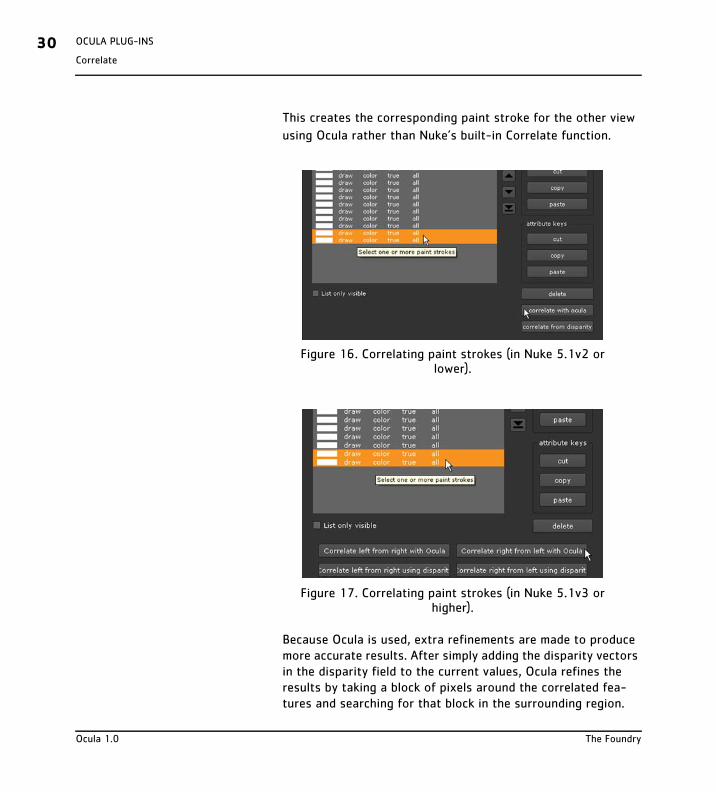
This creates the corresponding paint stroke for the other view
using Ocula rather than Nuke’s built-in Correlate function.
Because Ocula is used, extra refinements are made to produce more accurate results. After simply adding the disparity vectors in the disparity field to the current values, Ocula refines the results by taking a block of pixels around the correlated fea-tures and searching for that block in the surrounding region.
Figure 16. Correlating paint strokes (in Nuke 5.1v2 or lower).
Figure 17. Correlating paint strokes (in Nuke 5.1v3 or higher).
Ocula 1.0 The Foundry
Correlate
OCULA PLUG-INS 31
When it finds a match, it then adjusts the results of the correla-tion accordingly. If necessary, you can define the size of this block (in pixels) using the blocksize parameter and the size of the search region using searchsize.
8. In the Viewer, switch between the two views to compare the original and the correlated paint strokes.
9. If you want to adjust the paint stroke further, you need to adjust both views independently. Adjustments you make to one view are not automatically generated for the other.
Rotoscoping
To create a roto shape on one view and have it automatically generated for the other using Ocula, do the following:
1. If there are disparity vectors in the data stream from an earlier O_DisparityGenerator node, or if disparity vectors exist in the image sequence itself, these are used when calculating where a roto shape in one view should appear in the other. If disparity vectors don’t yet exists in the script, however, you can use the O_DisparityGenerator plug-in after your image sequence to cal-culate the disparity vectors.
2. Insert a Bezier node after either the O_DisparityGenerator node (if you added one in the previous step) or the image sequence you are manipulating.
3. With the Bezier controls open, create a roto shape for one view.
4. If you are using Nuke 5.1v2 or lower, display the other view using the Viewer controls.
If you are using Nuke 5.1v3 or higher, you can skip this step.
5. Go to the Bezier controls. From the View menu next to the shape control, select Correlate [view] from [view] with Ocula, for example Correlate left from right with Ocula. This adds a
The Foundry Ocula 1.0
OCULA PLUG-INS32Correlate
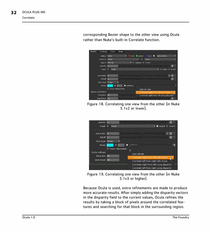
corresponding Bezier shape to the other view using Ocula
rather than Nuke’s built-in Correlate function.
Because Ocula is used, extra refinements are made to produce more accurate results. After simply adding the disparity vectors in the disparity field to the current values, Ocula refines the results by taking a block of pixels around the correlated fea-tures and searching for that block in the surrounding region.
Figure 18. Correlating one view from the other (in Nuke 5.1v2 or lower).
Figure 19. Correlating one view from the other (in Nuke 5.1v3 or higher).
Ocula 1.0 The Foundry
Correlate
OCULA PLUG-INS 33
When it finds a match, it then adjusts the results of the correla-tion accordingly. If necessary, you can define the size of this block (in pixels) using the blocksize parameter and the size of the search region using searchsize.
6. If you want to adjust the Bezier shape further, you need to adjust both views independently. Adjustments you make to one view are not automatically generated for the other.
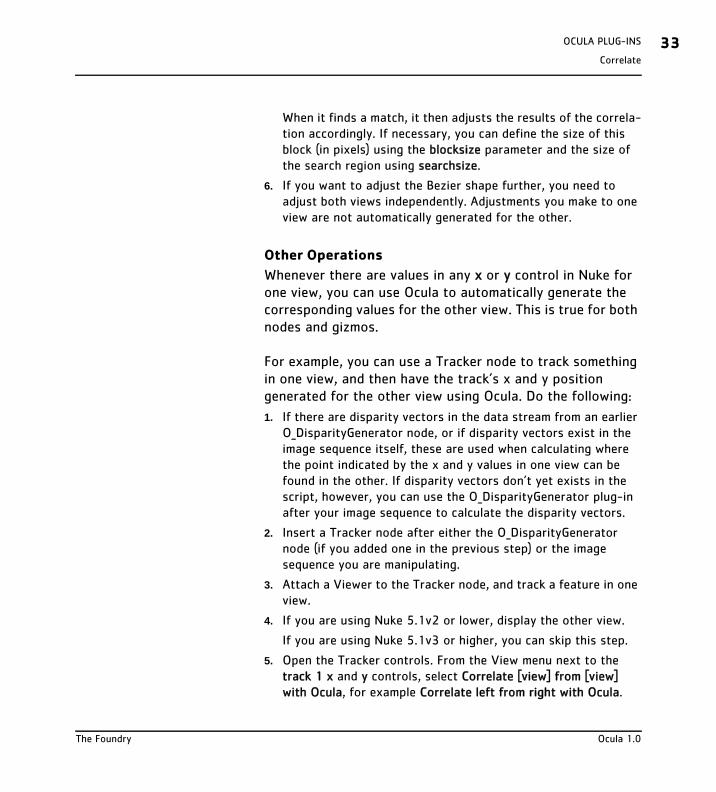
Other Operations
Whenever there are values in any x or y control in Nuke for one view, you can use Ocula to automatically generate the corresponding values for the other view. This is true for both nodes and gizmos.
For example, you can use a Tracker node to track something in one view, and then have the track’s x and y position generated for the other view using Ocula. Do the following:
1. If there are disparity vectors in the data stream from an earlier O_DisparityGenerator node, or if disparity vectors exist in the image sequence itself, these are used when calculating where the point indicated by the x and y values in one view can be found in the other. If disparity vectors don’t yet exists in the script, however, you can use the O_DisparityGenerator plug-in after your image sequence to calculate the disparity vectors.
2. Insert a Tracker node after either the O_DisparityGenerator node (if you added one in the previous step) or the image sequence you are manipulating.
3. Attach a Viewer to the Tracker node, and track a feature in one view.
4. If you are using Nuke 5.1v2 or lower, display the other view.
If you are using Nuke 5.1v3 or higher, you can skip this step.
5. Open the Tracker controls. From the View menu next to the track 1 x and y controls, select Correlate [view] from [view] with Ocula, for example Correlate left from right with Ocula.
The Foundry Ocula 1.0
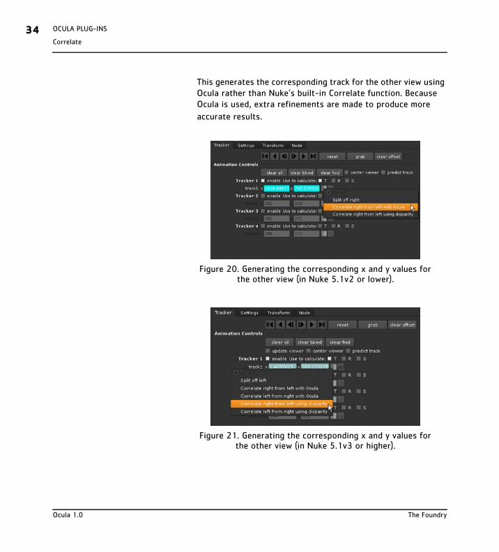
OCULA PLUG-INS34Correlate
This generates the corresponding track for the other view using Ocula rather than Nuke’s built-in Correlate function. Because Ocula is used, extra refinements are made to produce more
accurate results.
Figure 20. Generating the corresponding x and y values for the other view (in Nuke 5.1v2 or lower).
Figure 21. Generating the corresponding x and y values for the other view (in Nuke 5.1v3 or higher).
Ocula 1.0 The Foundry
Correlate
OCULA PLUG-INS 35
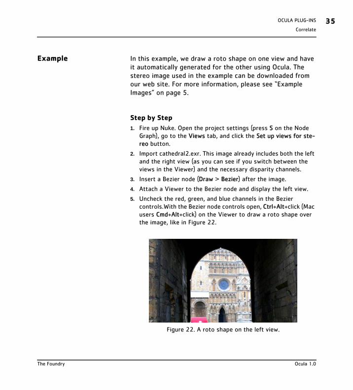
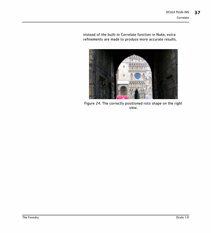
Example In this example, we draw a roto shape on one view and have it automatically generated for the other using Ocula. The stereo image used in the example can be downloaded from our web site. For more information, please see “Example Images” on page 5.
Step by Step
1. Fire up Nuke. Open the project settings (press S on the Node Graph), go to the Views tab, and click the Set up views for ste-reo button.
2. Import cathedral2.exr. This image already includes both the left and the right view (as you can see if you switch between the views in the Viewer) and the necessary disparity channels.
3. Insert a Bezier node (Draw > Bezier) after the image.
4. Attach a Viewer to the Bezier node and display the left view.
5. Uncheck the red, green, and blue channels in the Bezier controls.With the Bezier node controls open, Ctrl+Alt+click (Mac users Cmd+Alt+click) on the Viewer to draw a roto shape over the image, like in Figure 22.
Figure 22. A roto shape on the left view.
The Foundry Ocula 1.0
OCULA PLUG-INS36Correlate
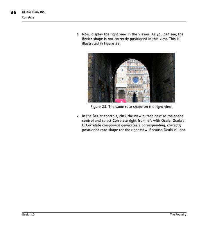
6. Now, display the right view in the Viewer. As you can see, the Bezier shape is not correctly positioned in this view. This is illustrated in Figure 23.
7. In the Bezier controls, click the view button next to the shape control and select Correlate right from left with Ocula. Ocula’s O_Correlate component generates a corresponding, correctly positioned roto shape for the right view. Because Ocula is used
Figure 23. The same roto shape on the right view.
Ocula 1.0 The Foundry
Correlate
OCULA PLUG-INS 37
instead of the built-in Correlate function in Nuke, extra refinements are made to produce more accurate results.
Figure 24. The correctly positioned roto shape on the right view.
The Foundry Ocula 1.0
OCULA PLUG-INS38InterocularShifter
InterocularShifter
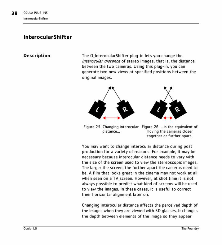
Description The O_InterocularShifter plug-in lets you change the interocular distance of stereo images; that is, the distance between the two cameras. Using this plug-in, you can generate two new views at specified positions between the original images.
You may want to change interocular distance during post production for a variety of reasons. For example, it may be necessary because interocular distance needs to vary with the size of the screen used to view the stereoscopic images. The larger the screen, the further apart the cameras need to be. A film that looks great in the cinema may not work at all when seen on a TV screen. However, at shot time it is not always possible to predict what kind of screens will be used to view the images. In these cases, it is useful to correct their horizontal alignment later on.
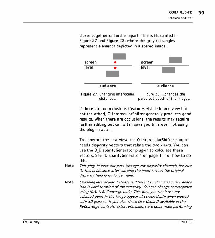
Changing interocular distance affects the perceived depth of the images when they are viewed with 3D glasses. It changes the depth between elements of the image so they appear
Figure 25. Changing interocular distance...
Figure 26. ...is the equivalent of moving the cameras closer together or further apart.
RL RL
Ocula 1.0 The Foundry
InterocularShifter
OCULA PLUG-INS 39
closer together or further apart. This is illustrated in Figure 27 and Figure 28, where the grey rectangles represent elements depicted in a stereo image.
If there are no occlusions (features visible in one view but not the other), O_InterocularShifter generally produces good results. When there are occlusions, the results may require further editing but can often save you time over not using the plug-in at all.
To generate the new view, the O_InterocularShifter plug-in needs disparity vectors that relate the two views. You can use the O_DisparityGenerator plug-in to calculate these vectors. See “DisparityGenerator” on page 11 for how to do this.
Note This plug-in does not pass through any disparity channels fed into it. This is because after warping the input images the original disparity field is no longer valid.
Note Changing interocular distance is different to changing convergence (the inward rotation of the cameras). You can change convergence using Nuke’s ReConverge node. This way, you can have any selected point in the image appear at screen depth when viewed with 3D glasses. If you also check Use Ocula if available in the ReConverge controls, extra refinements are done when performing
Figure 27. Changing interocular distance...
Figure 28. ...changes the perceived depth of the images.
audience
screen level
screen level
audience
The Foundry Ocula 1.0
OCULA PLUG-INS40InterocularShifter
the convergence shift. For more information on the ReConverge node, refer to the Nuke User Guide.
Quick Start To change interocular distance, do the following:
1. If there are disparity vectors in the data stream from an earlier O_DisparityGenerator node, or if disparity vectors exist in the image sequence itself, these are used when generating the two new views. If disparity vectors don’t yet exists in the script, however, you can use the O_DisparityGenerator plug-in after your image sequence to calculate the disparity vectors. See “DisparityGenerator” on page 11 for how to do this.
2. From the toolbar, select Ocula > O_InterocularShifter to insert an O_InterocularShifter node after either the O_DisparityGenerator node (if you added one in the previous step) or the image sequence whose interocular distance you want to adjust.
3. Under Views to Use, select the views you want to use to create new views.
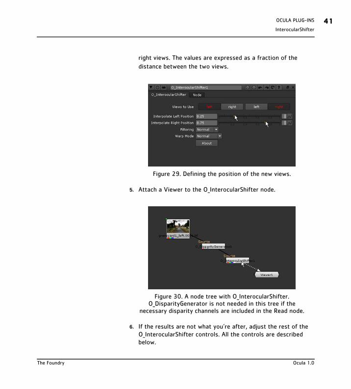
4. Use the Interpolate Left Position and Interpolate Right Position sliders to indicate where you want to build the new left and
Ocula 1.0 The Foundry
InterocularShifter
OCULA PLUG-INS 41
right views. The values are expressed as a fraction of the
distance between the two views.
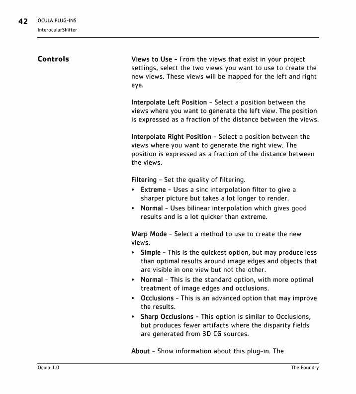
5. Attach a Viewer to the O_InterocularShifter node.
6. If the results are not what you’re after, adjust the rest of the O_InterocularShifter controls. All the controls are described below.
Figure 29. Defining the position of the new views.
Figure 30. A node tree with O_InterocularShifter. O_DisparityGenerator is not needed in this tree if the
necessary disparity channels are included in the Read node.
The Foundry Ocula 1.0
OCULA PLUG-INS42InterocularShifter
Controls Views to Use - From the views that exist in your project settings, select the two views you want to use to create the new views. These views will be mapped for the left and right eye.
Interpolate Left Position - Select a position between the views where you want to generate the left view. The position is expressed as a fraction of the distance between the views.
Interpolate Right Position - Select a position between the views where you want to generate the right view. The position is expressed as a fraction of the distance between the views.
Filtering - Set the quality of filtering.
• Extreme - Uses a sinc interpolation filter to give a sharper picture but takes a lot longer to render.
• Normal - Uses bilinear interpolation which gives good results and is a lot quicker than extreme.
Warp Mode - Select a method to use to create the new views.
• Simple - This is the quickest option, but may produce less than optimal results around image edges and objects that are visible in one view but not the other.
• Normal - This is the standard option, with more optimal treatment of image edges and occlusions.
• Occlusions - This is an advanced option that may improve the results.
• Sharp Occlusions - This option is similar to Occlusions, but produces fewer artifacts where the disparity fields are generated from 3D CG sources.
About - Show information about this plug-in. The
Ocula 1.0 The Foundry
InterocularShifter
OCULA PLUG-INS 43
information includes the plug-in’s version number and help text as well as the location of this user guide. You can also click the ? button on the O_InterocularShifter properties panel to display the same information.
Example This example shows you how to change the interocular distance of stereo images. You can download the image used here from our web site. For more information, please see “Example Images” on page 5.
Step by Step
1. Start Nuke and open the project settings by pressing S on the Node Graph. Go to the Views tab and click the Set up views for stereo button.
2. Import bench.exr. This image already includes both the left and the right view as well as the necessary disparity channels.
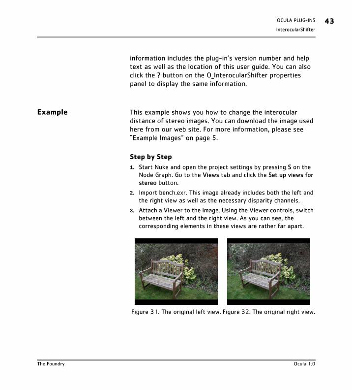
3. Attach a Viewer to the image. Using the Viewer controls, switch between the left and the right view. As you can see, the corresponding elements in these views are rather far apart.
Figure 31. The original left view. Figure 32. The original right view.
The Foundry Ocula 1.0
OCULA PLUG-INS44InterocularShifter
4. To reduce the interocular distance, select Ocula > O_InterocularShifter to insert an O_InterocularShifter node between the image and the Viewer.
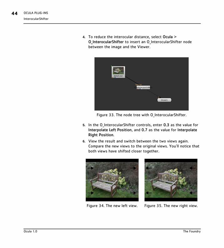
5. In the O_InterocularShifter controls, enter 0.3 as the value for Interpolate Left Position, and 0.7 as the value for Interpolate Right Position.
6. View the result and switch between the two views again. Compare the new views to the original views. You’ll notice that both views have shifted closer together.
Figure 33. The node tree with O_InterocularShifter.
Figure 34. The new left view. Figure 35. The new right view.
Ocula 1.0 The Foundry
NewView
OCULA PLUG-INS 45
NewView
Description Using the O_NewView plug-in, you can create a single view from a stereo pair of images. You can create this new view at any position between the original views. The new view replaces both of the existing views.
You can choose to construct the new view using one or both of the original views. Using just one view can be useful if you want to manipulate it with a gizmo, a plug-in, or a graphics editor, for example, and copy your changes into the other view. You can make your changes to one view, and use the O_NewView plug-in to generate the other view with these changes reproduced in the correct position.
If there are no occlusions (features visible in one view but not the other), O_NewView generally produces good results. When there are occlusions, the results may require further editing but can often save you time over not using the plug-in at all.
To generate the new view, the O_NewView plug-in needs disparity vectors that relate the two views. You can use the O_DisparityGenerator plug-in to calculate these vectors. See “DisparityGenerator” on page 11 for how to do this.
If you use O_NewView to reproduce changes made to one view in the other view, you may want to create the disparity vectors using either the modified view and its corresponding view, or the original views with no changes applied. Which you choose depends on which you think will produce better disparity vectors. The former method may be preferable, if you are correcting an unwanted colour shift between views,
The Foundry Ocula 1.0
OCULA PLUG-INS46NewView
for example. The latter method usually works best if your changes in one view produce an occlusion in the images, for example, when using a texture replacement plug-in or painting something on one view in another application.
Note that to reproduce changes you’ve made using Nuke’s Paint node, Bezier node, or any node or gizmo that has controls for x and y coordinates, it is easier to use the O_Correlate plug-in described on page 35.
Quick Start To create a new view:
1. If there are disparity vectors in the data stream from an earlier O_DisparityGenerator node, or if disparity vectors exist in the image sequence itself, these are used when generating the new view. If disparity vectors don’t yet exists in the script, however, you can use the O_DisparityGenerator plug-in to calculate the disparity vectors. Select Ocula > O_DisparityGenerator to insert an O_DisparityGenerator node in an appropriate place in your script.
2. Select Ocula > O_NewView to insert an O_NewView node after either the O_DisparityGenerator node or the stereo image sequence.
3. Using the Views to Use controls, select the views you want to map for the left and right eye.
4. From the Inputs pulldown menu, select which input(s) you want to use to create the new view:
• Left - Only use the image mapped for the left eye to create the new view.
• Right - Only use the image mapped for the right eye to create the new view.
Ocula 1.0 The Foundry
NewView
OCULA PLUG-INS 47
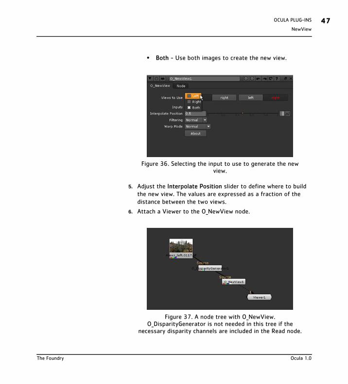
• Both - Use both images to create the new view.
5. Adjust the Interpolate Position slider to define where to build the new view. The values are expressed as a fraction of the distance between the two views.
6. Attach a Viewer to the O_NewView node.
Figure 36. Selecting the input to use to generate the new view.
Figure 37. A node tree with O_NewView. O_DisparityGenerator is not needed in this tree if the
necessary disparity channels are included in the Read node.
The Foundry Ocula 1.0
OCULA PLUG-INS48NewView
7. If you are not happy with the results, try adjusting the rest of the O_NewView controls. They are described below.
Controls Views to Use - From the views that exist in your project settings, select the two views you want to use to create the new view. These views will be mapped for the left and right eye.
Inputs - Select which inputs to use to generate the new view.
• Left - Only use the input mapped for the left eye to create the new view.
• Right - Only use the input mapped for the right eye to create the new view.
• Both - Use both inputs to create the new view.
Interpolate Position - Select the position between the existing views where you want to generate the new view. The position is expressed as a fraction of the distance between the views.
Filtering - Set the quality of filtering.
• Extreme - Uses a sinc interpolation filter to give a sharper picture but takes a lot longer to render.
• Normal - Uses bilinear interpolation which gives good results and is a lot quicker than extreme.
Warp Mode - Select a method to use to generate the new view.
• Simple - This is the quickest option, but may produce less than optimal results around image edges and objects that are visible in one view but not the other.
Ocula 1.0 The Foundry
NewView
OCULA PLUG-INS 49
• Normal - This is the standard option, with more optimal treatment of image edges and occlusions.
• Occlusions - This is an advanced option that may improve the results.
• Sharp Occlusions - This option is similar to Occlusions, but produces fewer artifacts where the disparity fields are generated from 3D CG sources.
About - Show information about this plug-in. The information includes the plug-in’s version number and help text as well as the location of this user guide. You can also click the ? button on the O_NewView properties panel to display the same information.
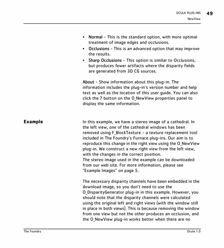
Example In this example, we have a stereo image of a cathedral. In the left view, one of the cathedral windows has been removed using F_BlockTexture - a texture replacement tool included in The Foundry’s Furnace plug-ins. Our aim is to reproduce this change in the right view using the O_NewView plug-in. We construct a new right view from the left view, with the changes in the correct position.The stereo image used in the example can be downloaded from our web site. For more information, please see “Example Images” on page 5.
The necessary disparity channels have been embedded in the download image, so you don’t need to use the O_DisparityGenerator plug-in in this example. However, you should note that the disparity channels were calculated using the original left and right views (with the window still in place in both views). This is because removing the window from one view but not the other produces an occlusion, and the O_NewView plug-in works better when there are no
The Foundry Ocula 1.0
OCULA PLUG-INS50NewView
occlusions.
Step by Step
1. Start Nuke and open the project settings (press S on the Node Graph). Go to the Views tab and click the Set up views for ste-reo button.
2. Import cathedral1.exr and attach a Viewer to the image. Switch between the left and the right view. Notice how in the left view, the cathedral has one window less than in the right view. This is highlighted in Figure 38 and Figure 39.
We want to reproduce this change made to the left view in the right view using the O_NewView plug-in.
3. Select Ocula > O_NewView to insert an O_NewView node between the stereo image and the Viewer. In the O_NewView controls, select Left from the Inputs menu to generate the new view from the left view. Enter 1 as the Interpolate Position to create the new view in the same position as the original right view.
Figure 38. The left view. Figure 39. The right view.
Ocula 1.0 The Foundry
NewView
OCULA PLUG-INS 51
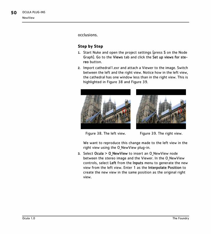
As you can see from Figure 40, the window disappears, but the O_NewView plug-in creates some unwanted changes around the edges of the new view.
To prevent this, we can take the area around the window from the new view, and composite that over the original right view.
4. Select the O_NewView node and Draw > Bezier from the Toolbar. This inserts a Bezier node after O_NewView.
5. In the Bezier controls, change the output to alpha, and premult to rgba. Attach the Viewer to cathedral1.exr, and view the right view.
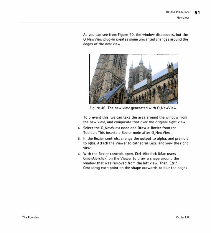
6. With the Bezier controls open, Ctrl+Alt+click (Mac users Cmd+Alt+click) on the Viewer to draw a shape around the window that was removed from the left view. Then, Ctrl/Cmd+drag each point on the shape outwards to blur the edges
Figure 40. The new view generated with O_NewView.
The Foundry Ocula 1.0
OCULA PLUG-INS52NewView
of the Bezier shape. Figure 41 shows a quickly drawn example
of what your Bezier shape might now look like.
7. Attach the Viewer to the Bezier node, and zoom out. You should only see the area you defined with the Bezier node. This is what we are going to composite over the original right view.
8. To extract the original right view from cathedral1.exr, click on an empty space in the Node Graph and select Views > OneView. Connect the OneView node into catherdal1.exr.
9. In the OneView controls, select right from the view menu. If you now view the output of OneView, you should see the original right view with the window still in place.
10. To composite the output from the Bezier node on top of the original right view, click on an empty spot in the Node Graph and select Merge > Merge. Connect the A input of the resulting over node into the Bezier and the B input into the OneView
Figure 41. Drawing a Bezier around the window.
Ocula 1.0 The Foundry
NewView
OCULA PLUG-INS 53
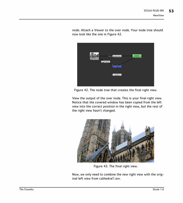
node. Attach a Viewer to the over node. Your node tree should now look like the one in Figure 42.
View the output of the over node. This is your final right view. Notice that the covered window has been copied from the left view into the correct position in the right view, but the rest of the right view hasn’t changed.
Now, we only need to combine the new right view with the orig-inal left view from cathedral1.exr.
Figure 42. The node tree that creates the final right view.
Figure 43. The final right view.
The Foundry Ocula 1.0
OCULA PLUG-INS54NewView
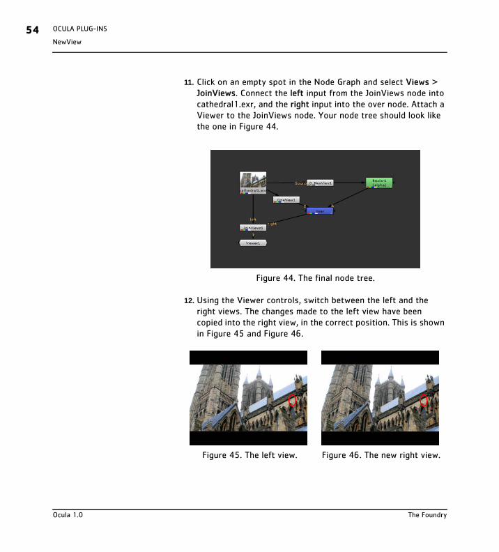
11. Click on an empty spot in the Node Graph and select Views > JoinViews. Connect the left input from the JoinViews node into cathedral1.exr, and the right input into the over node. Attach a Viewer to the JoinViews node. Your node tree should look like the one in Figure 44.
12. Using the Viewer controls, switch between the left and the right views. The changes made to the left view have been copied into the right view, in the correct position. This is shown in Figure 45 and Figure 46.
Figure 44. The final node tree.
Figure 45. The left view. Figure 46. The new right view.
Ocula 1.0 The Foundry
VerticalAligner
OCULA PLUG-INS 55
VerticalAligner
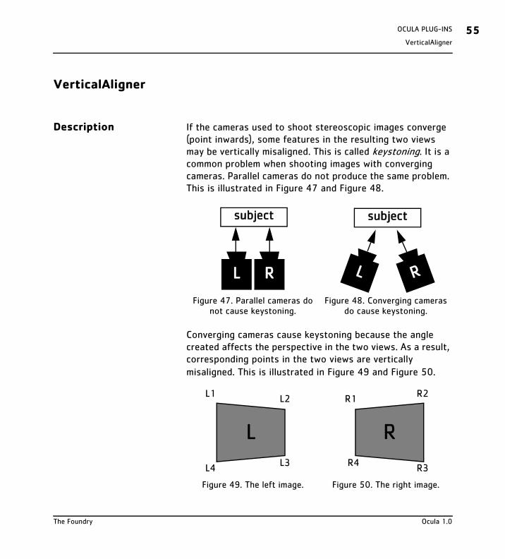
Description If the cameras used to shoot stereoscopic images converge (point inwards), some features in the resulting two views may be vertically misaligned. This is called keystoning. It is a common problem when shooting images with converging cameras. Parallel cameras do not produce the same problem. This is illustrated in Figure 47 and Figure 48.
Converging cameras cause keystoning because the angle created affects the perspective in the two views. As a result, corresponding points in the two views are vertically misaligned. This is illustrated in Figure 49 and Figure 50.
Figure 47. Parallel cameras do not cause keystoning.
Figure 48. Converging cameras do cause keystoning.
Figure 49. The left image. Figure 50. The right image.
L R
subject
RL
subject
L
L1L2
L3L4
R
R1R2
R3R4
The Foundry Ocula 1.0
OCULA PLUG-INS56VerticalAligner
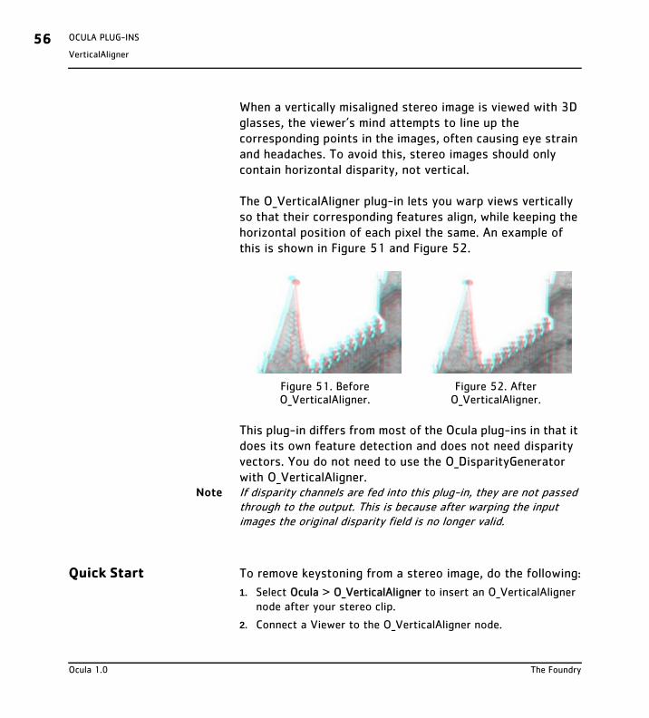
When a vertically misaligned stereo image is viewed with 3D glasses, the viewer’s mind attempts to line up the corresponding points in the images, often causing eye strain and headaches. To avoid this, stereo images should only contain horizontal disparity, not vertical.
The O_VerticalAligner plug-in lets you warp views vertically so that their corresponding features align, while keeping the horizontal position of each pixel the same. An example of this is shown in Figure 51 and Figure 52.
This plug-in differs from most of the Ocula plug-ins in that it does its own feature detection and does not need disparity vectors. You do not need to use the O_DisparityGenerator with O_VerticalAligner.
Note If disparity channels are fed into this plug-in, they are not passed through to the output. This is because after warping the input images the original disparity field is no longer valid.
Quick Start To remove keystoning from a stereo image, do the following:
1. Select Ocula > O_VerticalAligner to insert an O_VerticalAligner node after your stereo clip.
2. Connect a Viewer to the O_VerticalAligner node.
Figure 51. Before O_VerticalAligner.
Figure 52. After O_VerticalAligner.
Ocula 1.0 The Foundry
VerticalAligner
OCULA PLUG-INS 57
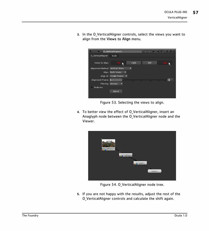
3. In the O_VerticalAligner controls, select the views you want to align from the Views to Align menu.
4. To better view the effect of O_VerticalAligner, insert an Anaglyph node between the O_VerticalAligner node and the Viewer.
5. If you are not happy with the results, adjust the rest of the O_VerticalAligner controls and calculate the shift again.
Figure 53. Selecting the views to align.
Figure 54. O_VerticalAligner node tree.
The Foundry Ocula 1.0
OCULA PLUG-INS58VerticalAligner
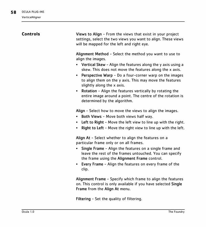
Controls Views to Align - From the views that exist in your project settings, select the two views you want to align. These views will be mapped for the left and right eye.
Alignment Method - Select the method you want to use to align the images.
• Vertical Skew - Align the features along the y axis using a skew. This does not move the features along the x axis.
• Perspective Warp - Do a four-corner warp on the images to align them on the y axis. This may move the features slightly along the x axis.
• Rotation - Align the features vertically by rotating the entire image around a point. The centre of the rotation is determined by the algorithm.
Align - Select how to move the views to align the images.
• Both Views - Move both views half way.
• Left to Right - Move the left view to line up with the right.
• Right to Left - Move the right view to line up with the left.
Align At - Select whether to align the features on a particular frame only or on all frames.
• Single Frame - Align the features on a single frame and leave the rest of the frames untouched. You can specify the frame using the Alignment Frame control.
• Every Frame - Align the features on every frame of the clip.
Alignment Frame - Specify which frame to align the features on. This control is only available if you have selected Single Frame from the Align At menu.
Filtering - Set the quality of filtering.
Ocula 1.0 The Foundry
VerticalAligner
OCULA PLUG-INS 59
• Extreme - Uses a sinc interpolation filter to give a sharper picture but takes a lot longer to render.
• Normal - Uses bilinear interpolation which gives good results and is a lot quicker than extreme.
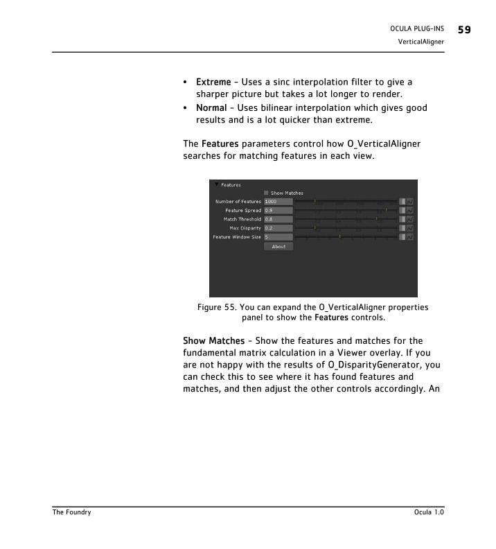
The Features parameters control how O_VerticalAligner searches for matching features in each view.
Show Matches - Show the features and matches for the fundamental matrix calculation in a Viewer overlay. If you are not happy with the results of O_DisparityGenerator, you can check this to see where it has found features and matches, and then adjust the other controls accordingly. An
Figure 55. You can expand the O_VerticalAligner properties panel to show the Features controls.
The Foundry Ocula 1.0
OCULA PLUG-INS60VerticalAligner
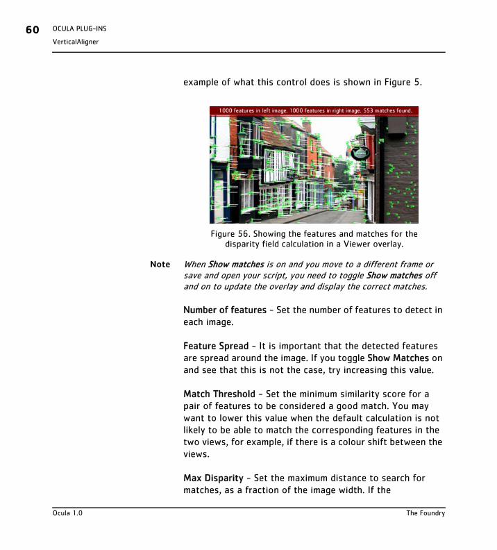
example of what this control does is shown in Figure 5.
Note When Show matches is on and you move to a different frame or save and open your script, you need to toggle Show matches off and on to update the overlay and display the correct matches.
Number of features - Set the number of features to detect in each image.
Feature Spread - It is important that the detected features are spread around the image. If you toggle Show Matches on and see that this is not the case, try increasing this value.
Match Threshold - Set the minimum similarity score for a pair of features to be considered a good match. You may want to lower this value when the default calculation is not likely to be able to match the corresponding features in the two views, for example, if there is a colour shift between the views.
Max Disparity - Set the maximum distance to search for matches, as a fraction of the image width. If the
Figure 56. Showing the features and matches for the disparity field calculation in a Viewer overlay.
Ocula 1.0 The Foundry
VerticalAligner
OCULA PLUG-INS 61
corresponding features in your images are far apart and you get poor results with the default settings, you may want to increase this value.
Feature Window Size - Set the width and height (in pixels) of the square window O_VerticalAligner tries to match around each feature.
Example In this example, we correct the vertical alignment of a stereo image. The image used here can be downloaded from our web site. For more information, please see “Example Images” on page 5.
Step by Step
1. Fire up Nuke. Open the project settings (press S on the Node Graph), go to the Views tab, and click the Set up views for ste-reo button.
2. Import the steep_hill.exr image. The image includes both the left and the right view. Because O_VerticalAligner does the feature detection and matching itself, you do not need to insert an O_DisparityGenerator node in your script.
3. Insert an O_VerticalAligner (Ocula > O_VerticalAligner) and an Anaglyph node (Stereo > Views > Anaglyph) after the image.
The Foundry Ocula 1.0
OCULA PLUG-INS62VerticalAligner
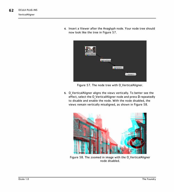
4. Insert a Viewer after the Anaglyph node. Your node tree should now look like the tree in Figure 57.
5. O_VerticalAligner aligns the views vertically. To better see the effect, select the O_VerticalAligner node and press D repeatedly to disable and enable the node. With the node disabled, the views remain vertically misaligned, as shown in Figure 58.
Figure 57. The node tree with O_VerticalAligner.
Figure 58. The zoomed in image with the O_VerticalAligner node disabled.
Ocula 1.0 The Foundry
VerticalAligner
OCULA PLUG-INS 63
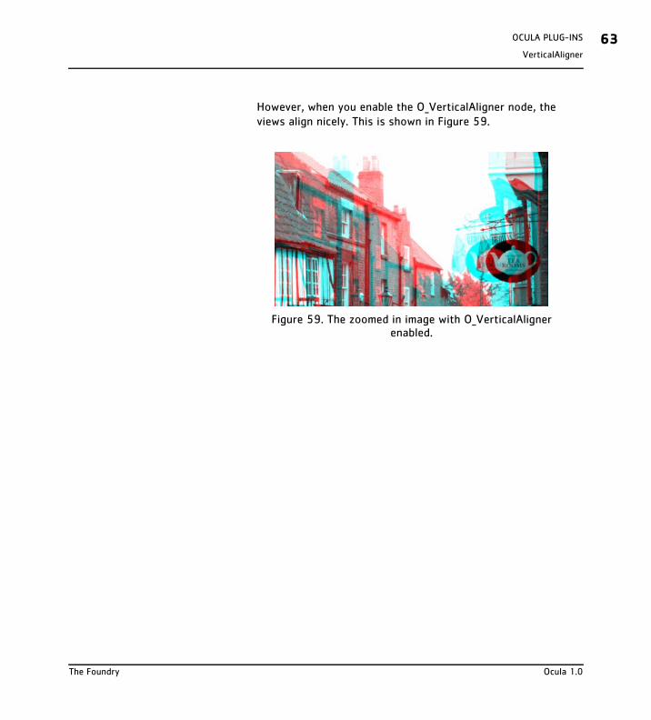
However, when you enable the O_VerticalAligner node, the views align nicely. This is shown in Figure 59.
Figure 59. The zoomed in image with O_VerticalAligner enabled.
The Foundry Ocula 1.0

OCULA PLUG-INS64VerticalAligner
Ocula 1.0 The Foundry
Release Notes
APPENDIX A 65
APPENDIX A
Release Notes This section describes the requirements, new features, improvements, fixed bugs and known bugs & workarounds for each release of Ocula.
Ocula 1.0v1 This is the first release of Ocula 1.0 for Nuke.
Release Date
October 2008
Requirements
1. Nuke 5.1 on Windows, Mac OS X, or Linux.
2. Foundry FLEXlm Tools (FFT 4.0v1 or later) for floating licenses.
New Features
In this release, there are five plug-ins and a collection of tools that add extra functionality to existing Nuke features.
Improvements
This section will describe improvements to existing features in later versions.
Bug Fixes
This section will describe fixed bugs in later versions.
The Foundry Ocula 1.0
APPENDIX A66Release Notes
Known Bugs and Workarounds
• BUG ID 5482 - Progress bar does not indicate what is being processed further up a tree when "Correlate using disparity" or "Correlate with Ocula" options are used. This will be fixed in a subsequent Nuke release.
• BUG ID 5904 - There is no progress bar when "Correlate with Ocula" option is used. This will be fixed in a subsequent Nuke release.
• BUG ID 5979 - Running out of memory with complicated stereo scripts on 32-bit Windows. This will be fixed in a subsequent Nuke release.
• BUG ID 6075- Slow processing when "Correlate with Ocula" option is used if source image is an EXR. This will be fixed in a subsequent Nuke release.
• BUG ID 6428 - ReConverge node: "Use Ocula if available" option causes a crash when reloading a script. This will be fixed in Nuke 5.1v3.
Ocula 1.0 The Foundry
End User License Agreement
APPENDIX B 67
APPENDIX B
End User License Agreement
IMPORTANT: BY INSTALLING THIS SOFTWARE YOU ACKNOWLEDGE THAT YOU HAVE READ THIS AGREEMENT, UNDERSTAND IT AND AGREE TO BE BOUND BY ITS TERMS AND CONDITIONS. IF YOU DO NOT AGREE TO THE TERMS OF THIS AGREEMENT DO NOT INSTALL, COPY OR USE THE SOFT-WARE.
This END USER SOFTWARE LICENSE AGREEMENT (this "Agreement") is made by and between The Foundry Visionmongers Ltd., a company registered in England and Wales, ("The Foundry"), and you, as either an individual or a single entity ("Licensee").
In consideration of the mutual covenants contained herein and for other good and valuable consid-eration (the receipt and sufficiency of which is acknowledged by each party hereto) the parties agree as follows:
SECTION 1. GRANT OF LICENSE.
Subject to the limitations of Section 2, The Foundry hereby grants to Licensee a limited, non-trans-ferable and non-exclusive license to install and use a machine readable, object code version of this software program (the "Software") and the accompanying user guide and other documentation (col-lectively, the "Documentation") solely for Licensee's own internal business purposes (collectively, the "License"); provided, however, Licensee's right to install and use the Software and the Documenta-tion is limited to those rights expressly set out in this Agreement.
SECTION 2. RESTRICTIONS ON USE.
Licensee is authorized to use the Software in machine readable, object code form only, and Licensee shall not: (a) assign, sublicense, transfer, pledge, lease, rent, share or export the Software, the Doc-umentation or Licensee's rights hereunder; (b) alter or circumvent the copy protection mechanisms in the Software or reverse engineer, decompile, disassemble or otherwise attempt to discover the source code of the Software; (c) modify, adapt, translate or create derivative works based on the Software or Documentation; (d) use, or allow the use of, the Software or Documentation on any project other than a project produced by Licensee (an "Authorized Project"); (e) allow or permit any-one (other than Licensee and Licensee's authorized employees to the extent they are working on an
The Foundry Ocula 1.0
APPENDIX B68End User License Agreement
Authorized Project) to use or have access to the Software or Documentation; (f) copy or install the Software or Documentation other than as expressly provided for herein; or (g) take any action, or fail to take action, that could adversely affect the trademarks, service marks, patents, trade secrets, copyrights or other intellectual property rights of The Foundry or any third party with intellectual property rights in the Software (each, a "Third Party Licensor"). Furthermore, for purposes of this Section 2, the term "Software" shall include any derivatives of the Software.
Licensee shall install and use only a single copy of the Software on one computer, unless the Soft-ware is installed in a "floating license" environment, in which case Licensee may install the Software on more than one computer; provided, however, Licensee shall not at any one time use more copies of the Software than the total number of valid Software licenses purchased by Licensee.
Furthermore, the Software can be licensed on an "interactive" or "non-interactive" basis. Licensee shall be authorized to use a non-interactive version of the Software for rendering purposes only (i.e., on a CPU, without a user, in a non-interactive capacity) and shall not use such Software on workstations or otherwise in a user-interactive capacity. Licensee shall be authorized to use an interactive version of the Software for both interactive and non-interactive rendering purposes, if available.
Finally, if the Software is an "Educational Version," Licensee may use it only for the purpose of train-ing and instruction, and for no other purpose. Educational Versions of the Software may not be used for commercial, professional or for-profit purposes.
SECTION 3. BACK-UP COPY.
Notwithstanding Section 2, Licensee may store one copy of the Software and Documentation off-line and off-site in a secured location owned or leased by Licensee in order to provide a back-up in the event of destruction by fire, flood, acts of war, acts of nature, vandalism or other incident. In no event may Licensee use the back-up copy of the Software or Documentation to circumvent the usage or other limitations set forth in this Agreement.
SECTION 4. OWNERSHIP.
Licensee acknowledges that the Software and Documentation and all intellectual property rights relating thereto are and shall remain the sole property of The Foundry and the Third Party Licensors. Licensee shall not remove, or allow the removal of, any copyright or other proprietary rights notice included in and on the Software or Documentation or take any other action that could adversely affect the property rights of The Foundry or any Third Party Licensor. To the extent that Licensee is authorized to make copies of the Software or Documentation under this Agreement, Licensee shall
Ocula 1.0 The Foundry
End User License Agreement
APPENDIX B 69
reproduce in and on all such copies any copyright and/or other proprietary rights notices provided in and on the materials supplied by The Foundry hereunder. Nothing in this Agreement shall be deemed to give Licensee any rights in the trademarks, service marks, patents, trade secrets, copyrights or other intellectual property rights of The Foundry or any Third Party Licensor, and Licensee shall be strictly prohibited from using the name, trademarks or service marks of The Foundry or any Third Party Licensor in Licensee's promotion or publicity without The Foundry's express written approval.
SECTION 5. LICENSE FEE.
Licensee understands that the benefits granted to Licensee hereunder are contingent upon Lic-ensee's payment in full of the license fee payable in connection herewith (the "License Fee").
SECTION 6. TAXES AND DUTIES.
Licensee agrees to pay, and indemnify The Foundry from claims for, any local, state or national tax (exclusive of taxes based on net income), duty, tariff or other impost related to or arising from the transaction contemplated by this Agreement.
SECTION 7. LIMITED WARRANTY.
The Foundry warrants that, for a period of ninety (90) days after delivery of the Software: (a) the machine readable electronic files constituting the Software and Documentation shall be free from errors that may arise from the electronic file transfer from The Foundry and/or its authorized reseller to Licensee; and (b) to the best of The Foundry's knowledge, Licensee's use of the Software in accordance with the Documentation will not, in and of itself, infringe any third party's copyright, patent or other intellectual property rights. Except as warranted, the Software and Documentation is being provided "as is." THE FOREGOING LIMITED WARRANTY IS IN LIEU OF ALL OTHER WARRAN-TIES OR CONDITIONS, EXPRESS OR IMPLIED, AND The Foundry DISCLAIMS ANY AND ALL IMPLIED WARRANTIES OR CONDITIONS, INCLUDING, WITHOUT LIMITATION, ANY IMPLIED WARRANTY OF TITLE, NON-INFRINGEMENT, MERCHANTABILITY OR FITNESS FOR A PARTICULAR PURPOSE, REGARDLESS OF WHETHER The Foundry KNOWS OR HAS REASON TO KNOW OF LICENSEE'S PARTIC-ULAR NEEDS. The Foundry does not warrant that the Software or Documentation will meet Lic-ensee's requirements or that Licensee's use of the Software will be uninterrupted or error free. No employee or agent of The Foundry is authorized to modify this limited warranty, nor to make addi-tional warranties. No action for any breach of the above limited warranty may be commenced more than one (1) year after Licensee's initial receipt of the Software. To the extent any implied warran-
The Foundry Ocula 1.0
APPENDIX B70End User License Agreement
ties may not be disclaimed under applicable law, then ANY IMPLIED WARRANTIES ARE LIMITED IN DURATION TO NINETY (90) DAYS AFTER DELIVERY OF THE SOFTWARE TO LICENSEE.
SECTION 8. LIMITED REMEDY.
The exclusive remedy available to the Licensee in the event of a breach of the foregoing limited war-ranty, TO THE EXCLUSION OF ALL OTHER REMEDIES, is for Licensee to destroy all copies of the Software, send The Foundry a written certification of such destruction and, upon The Foundry's receipt of such certification, The Foundry will make a replacement copy of the Software available to Licensee.
SECTION 9. INDEMNIFICATION.
Licensee agrees to indemnify, hold harmless and defend The Foundry and The Foundry's affiliates, officers, directors, shareholders, employees, authorized resellers, agents and other representatives (collectively, the "Released Parties") from all claims, defense costs (including, but not limited to, attorneys' fees), judgments, settlements and other expenses arising from or connected with the operation of Licensee's business or Licensee's possession or use of the Software or Documentation.
SECTION 10. LIMITED LIABILITY.
In no event shall the Released Parties' cumulative liability to Licensee or any other party for any loss or damages resulting from any claims, demands or actions arising out of or relating to this Agree-ment (or the Software or Documentation contemplated herein) exceed the License Fee paid to The Foundry or its authorized reseller for use of the Software. Furthermore, IN NO EVENT SHALL THE RELEASED PARTIES BE LIABLE TO LICENSEE UNDER ANY THEORY FOR ANY INDIRECT, SPECIAL, INCI-DENTAL, PUNITIVE, EXEMPLARY OR CONSEQUENTIAL DAMAGES (INCLUDING DAMAGES FOR LOSS OF BUSINESS OR LOSS OF PROFITS) OR THE COST OF PROCUREMENT OF SUBSTITUTE GOODS OR SERVICES, REGARDLESS OF WHETHER THE RELEASED PARTIES KNOW OR HAVE REASON TO KNOW OF THE POSSIBILITY OF SUCH DAMAGES AND REGARDLESS OF WHETHER ANY REMEDY SET FORTH HEREIN FAILS OF ITS ESSENTIAL PURPOSE. No action arising out of or related to this Agreement, regardless of form, may be brought by Licensee more than one (1) year after Licensee's initial receipt of the Software; provided, however, to the extent such one (1) year limit may not be valid under applicable law, then such period shall limited to the shortest period allowed by law.
Ocula 1.0 The Foundry
End User License Agreement
APPENDIX B 71
SECTION 11. TERM; TERMINATION.
This Agreement is effective upon Licensee's acceptance of the terms hereof (by clicking on the "Accept" button) and Licensee's payment of the License Fee, and the Agreement will remain in effect until termination. If Licensee breaches this Agreement, The Foundry may terminate the License granted hereunder by notice to Licensee. In the event the License is terminated, Licensee will either return to The Foundry all copies of the Software and Documentation in Licensee's possession or, if The Foundry directs in writing, destroy all such copies. In the later case, if requested by The Foundry, Licensee shall provide The Foundry with a certificate signed by an officer of Licensee con-firming that the foregoing destruction has been completed.
SECTION 12. CONFIDENTIALITY.
Licensee agrees that the Software and Documentation are proprietary and confidential information of The Foundry and that all such information and any communications relating thereto (collectively, "Confidential Information") are confidential and a fundamental and important trade secret of The Foundry. Licensee shall disclose Confidential Information only to Licensee's employees who are working on an Authorized Project and have a "need-to-know" such Confidential Information, and shall advise any recipients of Confidential Information that it is to be used only as authorized in this Agreement. Licensee shall not disclose Confidential Information or otherwise make any Confidential Information available to any other of Licensee's employees or to any third parties without the express written consent of The Foundry. Licensee agrees to segregate, to the extent it can be rea-sonably done, the Confidential Information from the confidential information and materials of others in order to prevent commingling. Licensee shall take reasonable security measures, which such mea-sures shall be at least as great as the measures Licensee uses to keep Licensee's own confidential information secure (but in any case using no less than a reasonable degree of care), to hold the Software, Documentation and any other Confidential Information in strict confidence and safe cus-tody. The Foundry may request, in which case Licensee agrees to comply with, certain reasonable security measures as part of the use of the Software and Documentation. Licensee acknowledges that monetary damages may not be a sufficient remedy for unauthorized disclosure of Confidential Information, and that The Foundry shall be entitled, without waiving any other rights or remedies, to such injunctive or equitable relief as may be deemed proper by a court of competent jurisdiction.
SECTION 13. INSPECTION.
Licensee shall advise The Foundry on demand of all locations where the Software or Documentation is used or stored. Licensee shall permit The Foundry or its authorized agents to inspect all such locations during normal business hours and on reasonable advance notice.
The Foundry Ocula 1.0
APPENDIX B72End User License Agreement
SECTION 14. NONSOLICITATION.
Licensee agrees not to solicit for employment or retention, and not to employ or retain, any of The Foundry's current or future employees who were or are involved in the development and/or creation of the Software.
SECTION 15. U.S. GOVERNMENT LICENSE RIGHTS.
The Software, Documentation and/or data delivered hereunder are subject to the terms of this Agreement and in no event shall the U.S. Government acquire greater than RESTRICTED/LIMITED RIGHTS. At a minimum, use, duplication or disclosure by the U.S. Government is subject to the appli-cable restrictions of: (i) FAR §52.227-14 ALTS I, II and III (June 1987); (ii) FAR §52.227-19 (June 1987); (iii) FAR §12.211 and 12.212; and/or (iv) DFARS §227.7202-1(a) and DFARS §227.7202-3.
The Software is the subject of the following notices:
* Copyright (c) 2007 The Foundry Visionmongers, Ltd.. All Rights Reserved.
* Unpublished-rights reserved under the Copyright Laws of the United Kingdom.
SECTION 16. SURVIVAL.
Sections 2, 4, 5, 6, 7, 8, 9, 10, 12, 13, 14, 15, 16, 17 and 18 shall survive any termination or expi-ration of this Agreement.
SECTION 17. IMPORT/EXPORT CONTROLS.
To the extent that any Software made available hereunder is subject to restrictions upon export and/or reexport from the United States, Licensee agrees to comply with, and not act or fail to act in any way that would violate, the applicable international, national, state, regional and local laws and regulations, including, without limitation, the United States Foreign Corrupt Practices Act, the Export Administration Act and the Export Administration Regulations, as amended or otherwise modified from time to time, and neither The Foundry nor Licensee shall be required under this Agree-ment to act or fail to act in any way which it believes in good faith will violate any such laws or reg-ulations.
Ocula 1.0 The Foundry
End User License Agreement
APPENDIX B 73
SECTION 18. MISCELLANEOUS.
This Agreement is the exclusive agreement between the parties concerning the subject matter hereof and supersedes any and all prior oral or written agreements, negotiations, or other dealings between the parties concerning such subject. This Agreement may be modified only by a written instrument signed by both parties. If any action is brought by either party to this Agreement against the other party regarding the subject matter hereof, the prevailing party shall be entitled to recover, in addition to any other relief granted, reasonable attorneys' fees and expenses of litigation. Should any term of this Agreement be declared void or unenforceable by any court of competent jurisdic-tion, such declaration shall have no effect on the remaining terms of this Agreement. The failure of either party to enforce any rights granted hereunder or to take action against the other party in the event of any breach hereunder shall not be deemed a waiver by that party as to subsequent enforce-ment of rights or subsequent actions in the event of future breaches. This Agreement shall be gov-erned by, and construed in accordance with English Law.
Copyright (c) 2008 The Foundry Visionmongers Ltd. All Rights Reserved. Do not duplicate.
The Foundry Ocula 1.0

APPENDIX B74End User License Agreement
Ocula 1.0 The Foundry
A-Z
INDEX 75
The Foundry Ocula 1.0
INDEX
A-Z
Aalignment
horizontal 28, 38vertical 55
Ccameras
converging 55parallel 55
colour discrepancies 23colours
matching between views 23converging cameras 55creating
a new view 45two new views 28
Ddisparity channel 13disparity fields 11disparity vectors 11
EEnd User License
Agreement 67
FFoundry, The 9
web site 10
Hhorizontal alignment
correcting 28, 38
Iinstallation 6
on Linux 7on Mac 6on Windows 6
Kkeystoning 55
LLicensing Furnace 8
Mmotion estimation 12
OO_ColourMatch 23O_Correlate 35O_DisparityGenerator 11O_InterocularShifter 28O_NewView 45O_VerticalAligner 55occlusions 39, 45
Ppaint effects 28parallel cameras 55
Rrelease notes 65, 67rotoscoping 23, 28
Ssystem requirements 6
TThe Foundry 9
web site 10The Foundry products 9
Vvertical alignment
correcting 56views
creating new 28, 45
Wweb site 10