OCTOPUS 300 - Frank's Hospital...
64
OCTOPUS 300 Service Manual HAAG STREIT No. 7220084 HAAG-STREIT AG, Switzerland, Phone: +41 31 978 01 11, Fax: +41 31 978 02 82, [email protected] HAAG-STREIT DEUTSCHLAND GmbH, Germany, Phone: +49 4103 709 02, Fax: +49 4103 709 370, [email protected] HAAG-STREIT FRANCE, France, Phone +33 4 5009 0033, Fax +33 4 5009 7190, [email protected] HAAG-STREIT UK, United Kingdom, Phone +44 1279 414969, Fax +44 1279 635232, [email protected] HAAG-STREIT USA, INC., USA, Phone: +1 513 336 6858, Fax: +1 513 336 7828, [email protected] OCTOPUS ® 300 Service Manual HS No. 7220084 8. Edition / 2014-08
Transcript of OCTOPUS 300 - Frank's Hospital...
OCTOPUS 300 Service Manual HAAG STREIT No. 7220084
HAAG-STREIT AG, Switzerland, Phone: +41 31 978 01 11, Fax: +41 31 978 02 82, [email protected]
HAAG-STREIT DEUTSCHLAND GmbH, Germany, Phone: +49 4103 709 02, Fax: +49 4103 709 370, [email protected]
HAAG-STREIT FRANCE, France, Phone +33 4 5009 0033, Fax +33 4 5009 7190, [email protected]
HAAG-STREIT UK, United Kingdom, Phone +44 1279 414969, Fax +44 1279 635232, [email protected]
HAAG-STREIT USA, INC., USA, Phone: +1 513 336 6858, Fax: +1 513 336 7828, [email protected]
OCTOPUS® 300
Service Manual HS No. 7220084
8. Edition / 2014-08
Tradition and Innovation
Page 2 / 64 OCTOPUS 300 Service Manual
TABLE OF CONTENTS
1 PARTS DELIVERED ......................................................................................................................................................................3
2 SAFETY INSTRUCTIONS ..............................................................................................................................................................4
2.1 General ................................................................................................................................................ 4 2.2 Instrument Transportation ................................................................................................................... 4 2.3 Symbols ............................................................................................................................................... 5 Special Notices in the Text ............................................................................................................................ 5
3 INTRODUCTION ............................................................................................................................................................................6
3.1 OCTOPUS Perimeter 300 ................................................................................................................... 6 3.2 Instrument Table ................................................................................................................................. 7 3.3 Installation ........................................................................................................................................... 8
4 SOFTWARE .................................................................................................................................................................................10
4.1 Installation, Exchange, Upgrade ....................................................................................................... 10 4.2 Releasing Program Options .............................................................................................................. 10
5 PRINCIPLE OF OPERATION ......................................................................................................................................................12
5.1 Functional Diagram ........................................................................................................................... 12 5.2 Stimulus Intensity Control ................................................................................................................. 12 5.3 Background Intensity Control ............................................................................................................ 14 5.4 Reference Point................................................................................................................................. 14 5.5 Optics Module ................................................................................................................................... 15
6 CARE AND MAINTENANCE .......................................................................................................................................................16
6.1 Cleaning ............................................................................................................................................ 16
7 MAINTENANCE AND REPAIR ....................................................................................................................................................17
7.1 Housing (1805001) ............................................................................................................................ 17 7.2 Optical Unit (1802669) ...................................................................................................................... 18 7.3 Z-Shaft (1802190) ............................................................................................................................. 19 7.4 Fixation Target (1802206) ................................................................................................................. 20 7.5 Correction Lens Holder (1007496) .................................................................................................... 22 7.6 Background Module, Lamp house (1802247) ................................................................................... 26 7.7 Brightness Regulator Module (1802248) .......................................................................................... 27 7.8 Stimulus Projector OCTOPUS 301(1802249)/ Stimulus Projector OCTOPUS 300 (1802544) ........ 31 7.9 Touch Screen Module (new version with TFT display) – Part No. 1802870..................................... 32 7.10 Lift-/Swivel Unit (1802241) ................................................................................................................ 34 7.11 Headrest Assembly ........................................................................................................................... 36 7.12 Power Supply (1802199) ................................................................................................................... 38 7.13 Processor Board I (1802431), Processor Board II (1802654) .......................................................... 38 7.14 SDRAM Module (1802152) ............................................................................................................... 44 7.15 Interface Board (1802224), Ethernet Interface Board (1802671) ..................................................... 47 7.16 Connector Board (1802213) .............................................................................................................. 48
8 SERVICE PROGRAMS ................................................................................................................................................................49
8.1 Subassembly Test ............................................................................................................................. 49 8.2 Service/Diagnostic............................................................................................................................. 50 8.3 Printer ................................................................................................................................................ 56 8.4 Dongle Codes .................................................................................................................................... 56 8.5 Light Intensity Calibration .................................................................................................................. 56 8.6 Entering Parameters ......................................................................................................................... 56 8.7 Verifying Calibration Parameters ...................................................................................................... 57 8.8 Instrument Information ...................................................................................................................... 58
9 SYSTEM MESSAGES ..................................................................................................................................................................59
9.1 Messages .......................................................................................................................................... 59 9.2 Errors ................................................................................................................................................. 59
10 APPENDIX....................................................................................................................................................................................62
10.1 Technical Data .................................................................................................................................. 62

Tradition and Innovation
OCTOPUS 300 Service Manual Page 3 / 64
1 PARTS DELIVERED
1 OCTOPUS perimeter 300 1802238 1 Set of accessories containing: 1802250
1 Patient response button 1802032 1 Dust cover 1802304 1 User's Manual 1802737 1 Ocular cover 1800339 3 Touch pens 1802303 1 Eye occluder (2 pieces) 1800339 2 FuesT3.15 A / 250 V 1801326 1 Allen (hexagon) wrench 2.5mm 1802338 1 Screwdriver 1802345 1 USB printer cable 1802347 1 Octopus VF Digest 1800092 1 FTP Server Installation 1802742
Tradition and Innovation
Page 4 / 64 OCTOPUS 300 Service Manual
2 SAFETY INSTRUCTIONS
2.1 General
This instrument can only be used for the purpose as described in this manual.
The examination of the patients, the operation of the instrument and the interpretation of the results can only be performed by persons who are experienced and who have been trained accordingly.
The instrument is to be installed on the height-adjustable table and employed in a dimly lit room in a medical area.
Keep this User's Manual there where persons who operate the instrument can consult it at all times. Guarantee claims can only be valid when the instructions in the User's Manual are followed.
The doctor or operator is to instruct the patient in the safety instructions and check that they are observed.
Make sure that the instrument is connected only to the power source as defined on the perimeter rating plate. The on/off switch does not separate the perimeter from the power lines. Before maintenance or cleaning work is performed, the power cord must be removed from the wall socket.
Removal of the housings and repairs to the instrument are permitted only by trained and authorized technicians. Considerable danger for the operator and patients can be caused by improper repairs.
Only original replacement parts and original accessories are permitted for repairs.
2.2 Instrument Transportation
Transport the instrument over large distances in the original packing. For short distances the instrument can be lifted using the two lower housing sides. Two ribbed grips are provided on the left and right sides which prevent from slipping sideways.
Do not use the forehead rest of the perimeter as a carrying handle. This plastic part is not adequate for the weight and can therefore break.
Tradition and Innovation
OCTOPUS 300 Service Manual Page 5 / 64
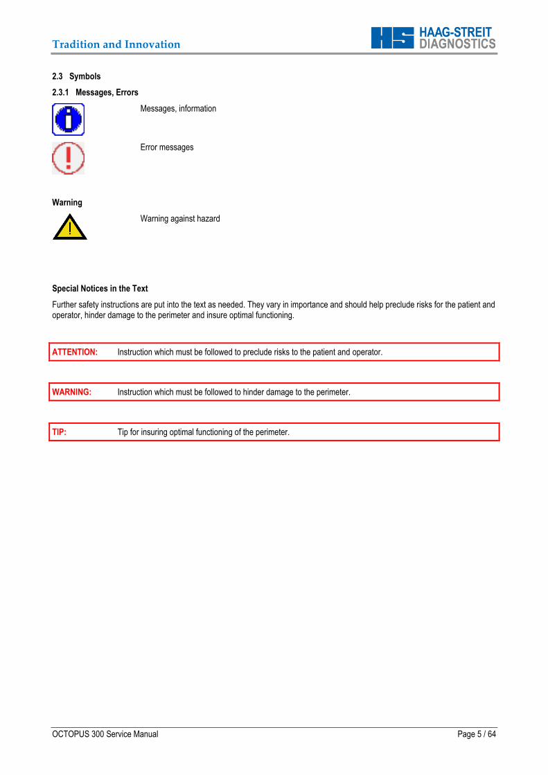
2.3 Symbols
2.3.1 Messages, Errors
Messages, information
Error messages
Warning
Warning against hazard
Special Notices in the Text
Further safety instructions are put into the text as needed. They vary in importance and should help preclude risks for the patient and operator, hinder damage to the perimeter and insure optimal functioning.
ATTENTION: Instruction which must be followed to preclude risks to the patient and operator.
WARNING: Instruction which must be followed to hinder damage to the perimeter.
TIP: Tip for insuring optimal functioning of the perimeter.

Tradition and Innovation
Page 6 / 64 OCTOPUS 300 Service Manual
3 INTRODUCTION
3.1 OCTOPUS Perimeter 300
The OCTOPUS 300 s a direct projection perimeter for examinations of the central visual field (30°). It is a stand-alone system, which means, the examination and control units are integrated into the instrument.
Figure 1
1 Optical unit with upper housing 2 Lower housing (left and right) 3 Grip locations (left and right) 4 Rotation and height adjustable instrument column for
fine positioning 5 Headrest with 6 Forehead rest with integrated sensors 7 Chin rest 8 Turning knob for chin rest positioning (rough
positioning) 9 Ocular 10 Trial lens holder with IR eye illumination 11 Connector for Patient response button
Figure 2
12 Turning knob for image focusing 13 Operating unit with LCD monitor and Touch module 14 Base with Connector panel and Power Supply
1
4
8
3
6
7
5
2
10
9
11
12
14
13
Tradition and Innovation
OCTOPUS 300 Service Manual Page 7 / 64
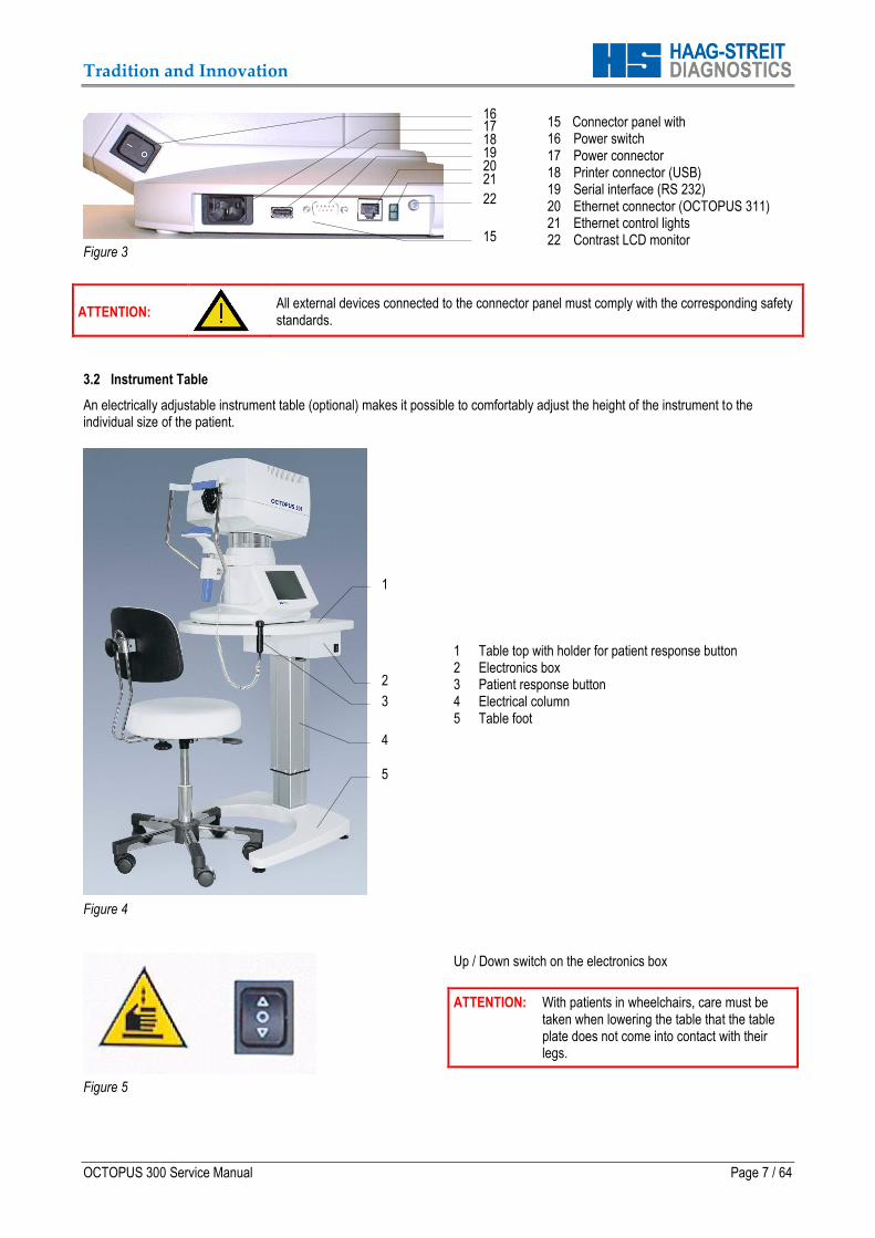
Figure 3
15 Connector panel with 16 Power switch 17 Power connector 18 Printer connector (USB) 19 Serial interface (RS 232) 20 Ethernet connector (OCTOPUS 311) 21 Ethernet control lights 22 Contrast LCD monitor
ATTENTION:
All external devices connected to the connector panel must comply with the corresponding safety standards.
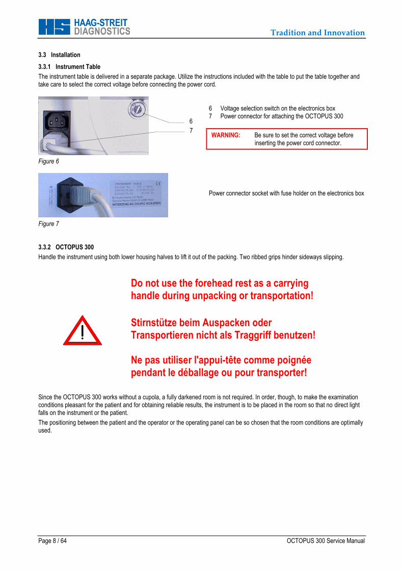
3.2 Instrument Table
An electrically adjustable instrument table (optional) makes it possible to comfortably adjust the height of the instrument to the individual size of the patient.
Figure 4
1 Table top with holder for patient response button 2 Electronics box 3 Patient response button 4 Electrical column 5 Table foot
Figure 5
Up / Down switch on the electronics box
ATTENTION: With patients in wheelchairs, care must be taken when lowering the table that the table plate does not come into contact with their legs.
1
2
4
5
3
16
19
17
21 20
18
22
15
Tradition and Innovation
Page 8 / 64 OCTOPUS 300 Service Manual
3.3 Installation
3.3.1 Instrument Table
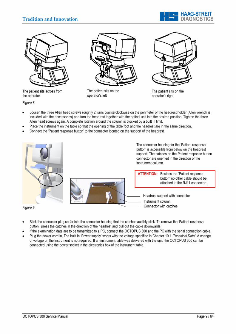
The instrument table is delivered in a separate package. Utilize the instructions included with the table to put the table together and take care to select the correct voltage before connecting the power cord.
Figure 6
6 Voltage selection switch on the electronics box 7 Power connector for attaching the OCTOPUS 300
WARNING: Be sure to set the correct voltage before inserting the power cord connector.
Figure 7
Power connector socket with fuse holder on the electronics box
3.3.2 OCTOPUS 300
Handle the instrument using both lower housing halves to lift it out of the packing. Two ribbed grips hinder sideways slipping. Since the OCTOPUS 300 works without a cupola, a fully darkened room is not required. In order, though, to make the examination conditions pleasant for the patient and for obtaining reliable results, the instrument is to be placed in the room so that no direct light falls on the instrument or the patient.
The positioning between the patient and the operator or the operating panel can be so chosen that the room conditions are optimally used.
6
7
Do not use the forehead rest as a carrying handle during unpacking or transportation!
Stirnstütze beim Auspacken oder Transportieren nicht als Traggriff benutzen! Ne pas utiliser l'appui-tête comme poignée pendant le déballage ou pour transporter!
Tradition and Innovation
OCTOPUS 300 Service Manual Page 9 / 64
The patient sits across from the operator
Figure 8
The patient sits on the operator's left
The patient sits on the operator's right
Loosen the three Allen head screws roughly 2 turns counterclockwise on the perimeter of the headrest holder (Allen wrench is included with the accessories) and turn the headrest together with the optical unit into the desired position. Tighten the three Allen head screws again. A complete rotation around the column is blocked by a built in limit.
Place the instrument on the table so that the opening of the table foot and the headrest are in the same direction.
Connect the ‘Patient response button’ to the connector located on the support of the headrest.
Figure 9
The connector housing for the ‘Patient response button’ is accessible from below on the headrest support. The catches on the Patient response button connector are oriented in the direction of the instrument column.
ATTENTION: Besides the ‘Patient response button’ no other cable should be attached to the RJ11 connector.
Stick the connector plug so far into the connector housing that the catches audibly click. To remove the ‘Patient response button’, press the catches in the direction of the headrest and pull out the cable downwards.
If the examination data are to be transmitted to a PC, connect the OCTOPUS 300 and the PC with the serial connection cable.
Plug the power cord in. The built in ‘Power supply’ works with the voltage specified in Chapter 10.1 'Technical Data'. A change of voltage on the instrument is not required. If an instrument table was delivered with the unit, the OCTOPUS 300 can be connected using the power socket in the electronics box of the instrument table.
Headrest support with connector
Instrument column
Connector with catches

Tradition and Innovation
Page 10 / 64 OCTOPUS 300 Service Manual
4 SOFTWARE
4.1 Installation, Exchange, Upgrade
For application software installation and upgrade refer to Chapter 7.14.1 'SIM Flash Module, Application Software (1802222). 4.2 Releasing Program Options
Some of the functions of the OCTOPUS 300 are offered as options and are not accessible in the basic version of the software. Basically all the functions are present in the software, but some can only be made accessible with a code. This code is delivered by HAAG STREIT and is then entered by the customer or the service technician into the instrument. Information about such additional functions can be obtained directly from HAAG STREIT or from your representative. 4.2.1 Procedure
Dongle codes
Read out software master data
Actual dongle code
Serial no.
Software version
Enter new dongle code. The keyboard is only released, when the serial number of the instrument is stored in the memory.
To print out the complete instrument information see Chapter 8.8 'Instrument Information'.
Procedure to make additional functions accessible in the perimeter.
IMPORTANT: The 'Dongle code' function is only used, when additional program options have been purchased. To avoid free access and faulty manipulations the function is protected. The 'Dongle' button is only released after the two headrest sensors and the 'Dongle' button are pressed at the same time. As from Serial No. 1031 the head rest sensors have been replaced with non-contact head sensors. In this case hold your hand (close) in front of the head rest and simultaneously press the ‘Dongle’ button.
Customer Sends the serial no., software version and the complete dongle code to HAAG STREIT or the representative and orders the desired supplementary function(s).
HAAG STREIT AG Based on the serial no. and the present and ordered option(s), the new dongle code is computed and given to the customer.
Customer Enters the complete new dongle code into the OCTOPUS 300.
Open dongle code tab.
Click on 'Dongle code' entry field (numerical keyboard will be displayed).
Enter complete dongle code into the three entry fields.
Close keyboard with 'Esc'.
Save new dongle code by clicking on Before the instrument saves the setting, the parameters are verified by the system. A faulty dongle code will not be saved. The message 'Dongle Code not accepted' is displayed on the screen. Delete wrong code and enter it the correct way.
OCTOPUS 300 The new additional functions are accessed via the graphical user interface.

Tradition and Innovation
OCTOPUS 300 Service Manual Page 11 / 64
4.2.2 Entering the Dongle Code
D o n g l e c o d e
The complete dongle code consists of a multi-digit three part series of numbers (see example on the left). Entering the code is done via 'Setup' – 'Service' – 'Dongle'
IMPORTANT: The additional functions are only made accessible when the dongle code is entered without any mistakes into the instrument it was created for.
4.2.3 The Results of Code Mistakes
Every dongle code is unique and only valid for a specific instrument. Mistakes made while entering it or the entering of it into the false instrument (false serial no.) have the consequence that only the basic functions are then accessible. Changing to the old code is possible at all times.
1234567890 123 1234
Tradition and Innovation
Page 12 / 64 OCTOPUS 300 Service Manual
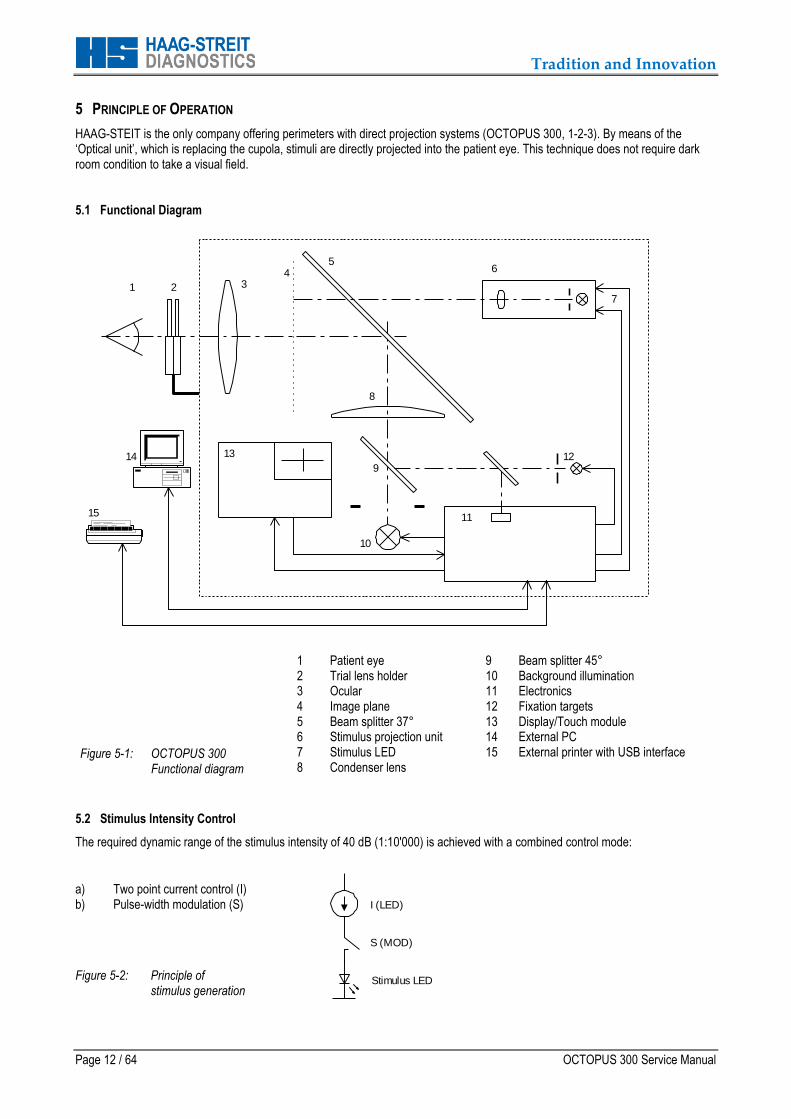
5 PRINCIPLE OF OPERATION
HAAG-STEIT is the only company offering perimeters with direct projection systems (OCTOPUS 300, 1-2-3). By means of the ‘Optical unit’, which is replacing the cupola, stimuli are directly projected into the patient eye. This technique does not require dark room condition to take a visual field. 5.1 Functional Diagram
1 32
45
10
149
7
8
6
11
1213
15
Figure 5-1: OCTOPUS 300 Functional diagram
1 Patient eye 9 Beam splitter 45° 2 Trial lens holder 10 Background illumination 3 Ocular 11 Electronics 4 Image plane 12 Fixation targets 5 Beam splitter 37° 13 Display/Touch module 6 Stimulus projection unit 14 External PC 7 Stimulus LED 15 External printer with USB interface 8 Condenser lens
5.2 Stimulus Intensity Control
The required dynamic range of the stimulus intensity of 40 dB (1:10'000) is achieved with a combined control mode:
a) Two point current control (I) b) Pulse-width modulation (S)
Figure 5-2: Principle of stimulus generation
I (LED)
S (MOD)
Stimulus LED
Tradition and Innovation
OCTOPUS 300 Service Manual Page 13 / 64
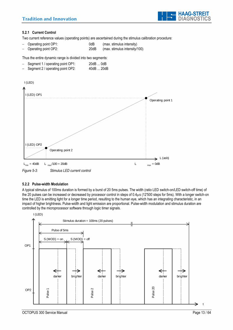
5.2.1 Current Control
Two current reference values (operating points) are ascertained during the stimulus calibration procedure:
Operating point OP1: 0dB (max. stimulus intensity)
Operating point OP2: 20dB (max. stimulus intensity/100) Thus the entire dynamic range is divided into two segments:
Segment 1 / operating point OP1: 20dB ... 0dB
Segment 2 / operating point OP2: 40dB ... 20dB
I (LED) OP1
I (LED) OP2
I (LED)
L (asb)
Lmin
= 40dB Lmax
/100 = 20dB Lmax
= 0dB
Operating point 1
Operating point 2
Figure 5-3: Stimulus LED current control 5.2.2 Pulse-width Modulation
A typical stimulus of 100ms duration is formed by a burst of 20 5ms pulses. The width (ratio LED switch-on/LED switch-off time) of
the 20 pulses can be increased or decreased by processor control in steps of 0.4s (12'500 steps for 5ms). With a longer switch-on time the LED is emitting light for a longer time period, resulting to the human eye, which has an integrating characteristic, in an impact of higher brightness. Pulse-width and light emission are proportional. Pulse-width modulation and stimulus duration are controlled by the microprocessor software through logic timer signals.
darker darkerdarker brighterbrighter brighter
Puls
e 1
Puls
e 2
0
Puls
e 2OP2
OP1
I (LED)
S (MOD) = on S (MOD) = off
Pulse of 5ms
Stimulus duration = 100ms (20 pulses)
t

Tradition and Innovation
Page 14 / 64 OCTOPUS 300 Service Manual
Figure 5-4: Stimulus LED pulse-width modulation 5.3 Background Intensity Control
The light source for the background illumination consists of a number of white LED’s. During initialization of the perimeter the background brightness is measured by a photo sensor and controlled by a DAC value. Pulse-width modulation is not used for background illumination. 5.4 Reference Point
During initialization of the perimeter the stimulus projection unit is centered to the optical system (position x/y = 0/0). The photo sensor for background illumination calibration is used as reference point.
Tradition and Innovation
OCTOPUS 300 Service Manual Page 15 / 64
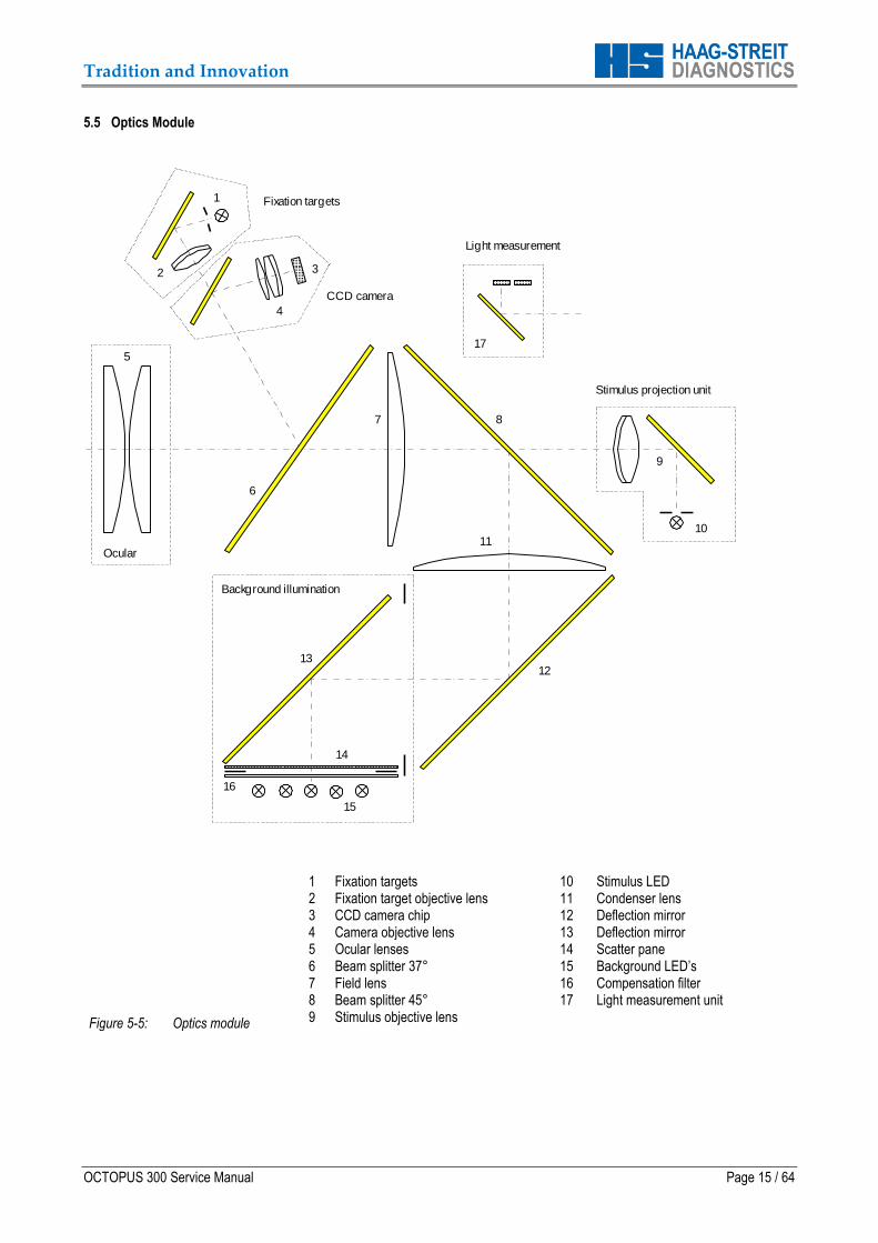
5.5 Optics Module
1
7
1110
6
5
32
8
4
9
1213
14
15
CCD camera
Fixation targets
Stimulus projection unit
Background illumination
Ocular
16
Light measurement
17
Figure 5-5: Optics module
1 Fixation targets 10 Stimulus LED 2 Fixation target objective lens 11 Condenser lens 3 CCD camera chip 12 Deflection mirror 4 Camera objective lens 13 Deflection mirror 5 Ocular lenses 14 Scatter pane 6 Beam splitter 37° 15 Background LED’s 7 Field lens 16 Compensation filter 8 Beam splitter 45° 17 Light measurement unit 9 Stimulus objective lens

Tradition and Innovation
Page 16 / 64 OCTOPUS 300 Service Manual
6 CARE AND MAINTENANCE
6.1 Cleaning
It suffices to dust the instrument periodically with a soft cloth. More obstinate dirt particles can be removed using a soft cloth
dampened slightly with water or alcohol.
ATTENTION: Avoid making the instrument wet and never use any solvents.
6.1.1 Patient Response Button, Chin and Headrest, Turning Knobs and Eye Occluder
All of these parts are made from plastic which can be cleaned with no problems. In order to keep them hygienically clean, they should be cleaned periodically with a cloth or cotton dampened with alcohol. 6.1.2 Ocular
Finger prints and dust can be removed with a moist soft cloth. 6.1.3 Monitor Screen, Touch Module
Finger prints and dust can be removed with a moist soft cloth.

Tradition and Innovation
OCTOPUS 300 Service Manual Page 17 / 64
7 MAINTENANCE AND REPAIR
WARNING: Before opening the instrument make sure that the mains cable is separated from the instrument.
WARNING: Some of the modules need alignment after being exchanged. Therefore it is important to go through all the steps described in exchanging the module that needs to be replaced.
WARNING: Electronic circuits of the OCTOPUS 300, particularly the 'Processor board', the 'Interface board' and the LEDs in the 'Background LED module' are all very sensitive to electrostatic charges. Keep all modules in static shielding bags for storage, transportation and shipping.
Besides an ordinary set of regular tools the following tools and instruments are recommended:
Set of Allan- (hexagonal) wrenches, metric 1.3 to 8mm
Set of Torx screwdrivers (the sizes in this manual refer to the screwdriver size)
Universal digital voltmeter, range 200mV to 250V Cleaning Materials
Can of compressed air
Lens tissue
Lens cleaner (diluted alcohol)
Cotton swabs Whenever possible, field repairs of the OCTOPUS 300 should be restricted to module exchange. The sub module (part) causing a problem should be localized with the help of the service manual and error list. It should then be replaced with an exchange module. 7.1 Housing (1805001)
Housing left
Housing right
Housing top
NOTE: If the 'Housing' is removed, the perimeter will only initialize and calibrate correctly if it is placed in an entirely dark environment. The covers can temporarily be put back in place for its operation and to run the 'Service programs' such as the 'General test' in a semi-dark room.
Removal
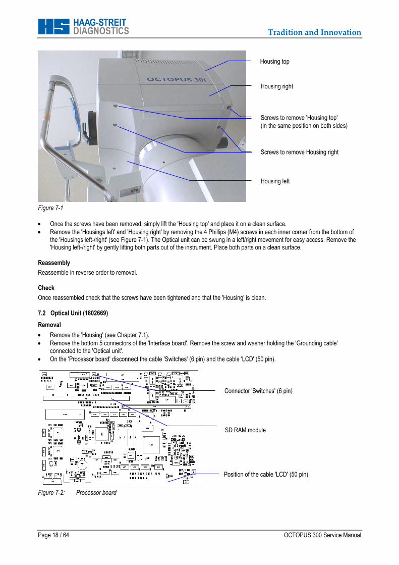
Remove the 'Housing top' by removing the four Phillips (M4) screws in each outer corner from the bottom part of the 'Housing left' and 'Housing right' (see Figure 7-1).
Tradition and Innovation
Page 18 / 64 OCTOPUS 300 Service Manual
Figure 7-1
Once the screws have been removed, simply lift the 'Housing top' and place it on a clean surface.
Remove the 'Housings left' and 'Housing right' by removing the 4 Phillips (M4) screws in each inner corner from the bottom of the 'Housings left-/right' (see Figure 7-1). The Optical unit can be swung in a left/right movement for easy access. Remove the 'Housing left-/right' by gently lifting both parts out of the instrument. Place both parts on a clean surface.
Reassembly
Reassemble in reverse order to removal. Check
Once reassembled check that the screws have been tightened and that the 'Housing' is clean. 7.2 Optical Unit (1802669)
Removal
Remove the 'Housing' (see Chapter 7.1).
Remove the bottom 5 connectors of the 'Interface board'. Remove the screw and washer holding the 'Grounding cable' connected to the 'Optical unit'.
On the 'Processor board' disconnect the cable 'Switches' (6 pin) and the cable 'LCD' (50 pin).
Figure 7-2: Processor board
Housing right
Housing top
Screws to remove 'Housing top'
(in the same position on both sides)
Screws to remove Housing right
Housing left
Position of the cable 'LCD' (50 pin)
SD RAM module
Connector 'Switches' (6 pin)
SD RAM module
Tradition and Innovation
OCTOPUS 300 Service Manual Page 19 / 64
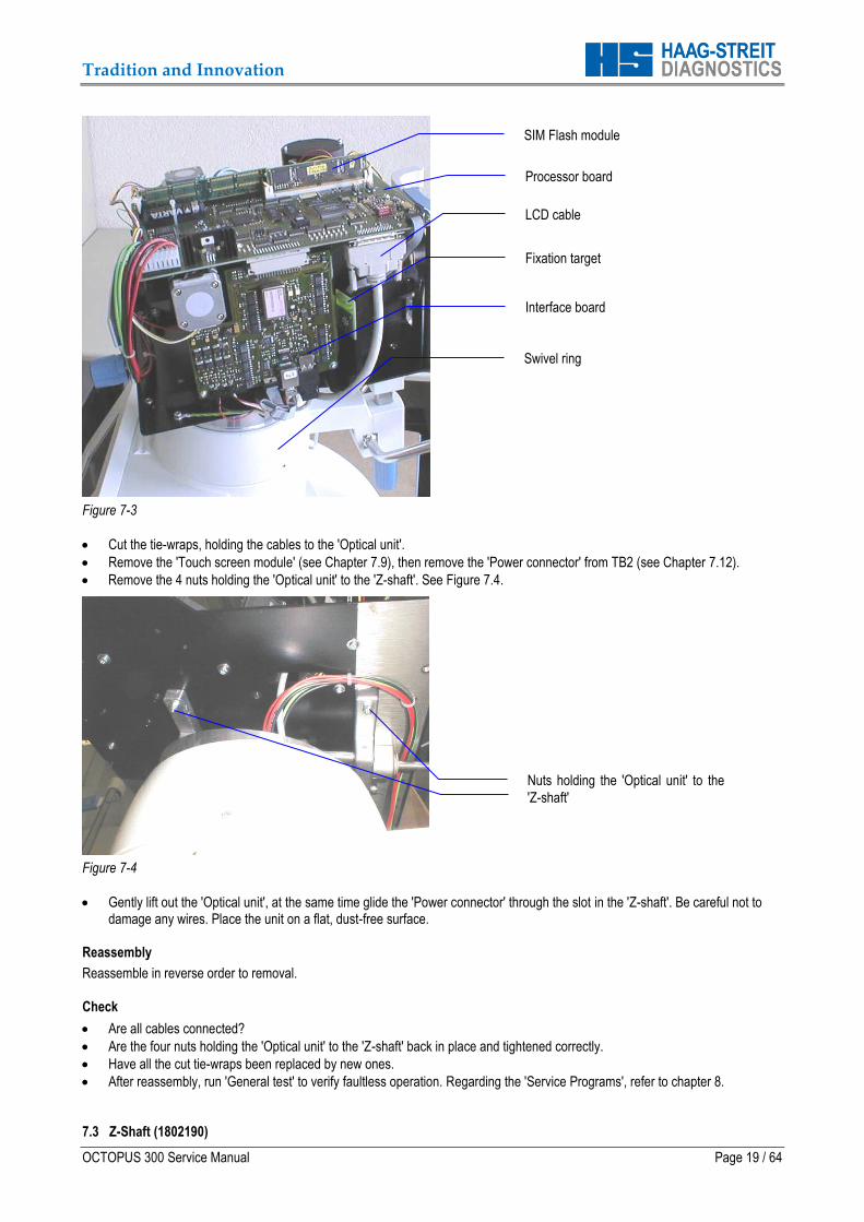
Figure 7-3
Cut the tie-wraps, holding the cables to the 'Optical unit'.
Remove the 'Touch screen module' (see Chapter 7.9), then remove the 'Power connector' from TB2 (see Chapter 7.12).
Remove the 4 nuts holding the 'Optical unit' to the 'Z-shaft'. See Figure 7.4.
Figure 7-4
Gently lift out the 'Optical unit', at the same time glide the 'Power connector' through the slot in the 'Z-shaft'. Be careful not to damage any wires. Place the unit on a flat, dust-free surface.
Reassembly
Reassemble in reverse order to removal. Check
Are all cables connected?
Are the four nuts holding the 'Optical unit' to the 'Z-shaft' back in place and tightened correctly.
Have all the cut tie-wraps been replaced by new ones.
After reassembly, run 'General test' to verify faultless operation. Regarding the 'Service Programs', refer to chapter 8. 7.3 Z-Shaft (1802190)
Nuts holding the 'Optical unit' to the
'Z-shaft'
Processor board
LCD cable
Fixation target
Interface board
Swivel ring
SIM Flash module
Processor board
Tradition and Innovation
Page 20 / 64 OCTOPUS 300 Service Manual
Removal
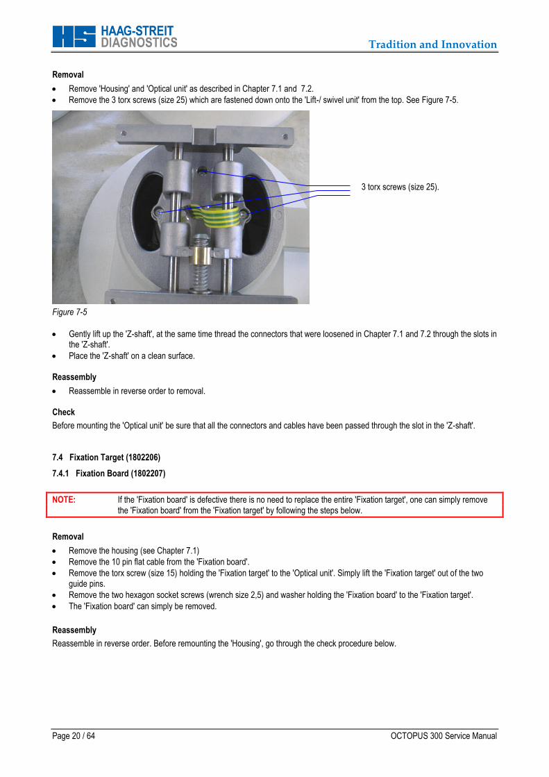
Remove 'Housing' and 'Optical unit' as described in Chapter 7.1 and 7.2.
Remove the 3 torx screws (size 25) which are fastened down onto the 'Lift-/ swivel unit' from the top. See Figure 7-5.
Figure 7-5
Gently lift up the 'Z-shaft', at the same time thread the connectors that were loosened in Chapter 7.1 and 7.2 through the slots in the 'Z-shaft'.
Place the 'Z-shaft' on a clean surface. Reassembly
Reassemble in reverse order to removal. Check
Before mounting the 'Optical unit' be sure that all the connectors and cables have been passed through the slot in the 'Z-shaft'. 7.4 Fixation Target (1802206)
7.4.1 Fixation Board (1802207)
NOTE: If the 'Fixation board' is defective there is no need to replace the entire 'Fixation target', one can simply remove the 'Fixation board' from the 'Fixation target' by following the steps below.
Removal
Remove the housing (see Chapter 7.1)
Remove the 10 pin flat cable from the 'Fixation board'.
Remove the torx screw (size 15) holding the 'Fixation target' to the 'Optical unit'. Simply lift the 'Fixation target' out of the two guide pins.
Remove the two hexagon socket screws (wrench size 2,5) and washer holding the 'Fixation board' to the 'Fixation target'.
The 'Fixation board' can simply be removed.
Reassembly
Reassemble in reverse order. Before remounting the 'Housing', go through the check procedure below.
3 torx screws (size 25).
Tradition and Innovation
OCTOPUS 300 Service Manual Page 21 / 64
Check
After replacement it is very important to check that the position of the 'Fixation target' is correct. To check use the Service functions.
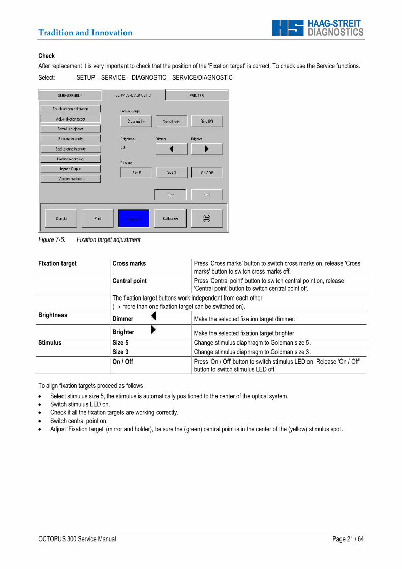
Select: SETUP – SERVICE – DIAGNOSTIC – SERVICE/DIAGNOSTIC
Figure 7-6: Fixation target adjustment
Fixation target Cross marks Press 'Cross marks' button to switch cross marks on, release 'Cross marks' button to switch cross marks off.
Central point Press 'Central point' button to switch central point on, release 'Central point' button to switch central point off.
The fixation target buttons work independent from each other
( more than one fixation target can be switched on).
Brightness Dimmer Make the selected fixation target dimmer.
Brighter Make the selected fixation target brighter.
Stimulus Size 5 Change stimulus diaphragm to Goldman size 5.
Size 3 Change stimulus diaphragm to Goldman size 3.
On / Off Press 'On / Off' button to switch stimulus LED on, Release 'On / Off' button to switch stimulus LED off.
To align fixation targets proceed as follows
Select stimulus size 5, the stimulus is automatically positioned to the center of the optical system.
Switch stimulus LED on.
Check if all the fixation targets are working correctly.
Switch central point on.
Adjust 'Fixation target' (mirror and holder), be sure the (green) central point is in the center of the (yellow) stimulus spot.
Tradition and Innovation
Page 22 / 64 OCTOPUS 300 Service Manual
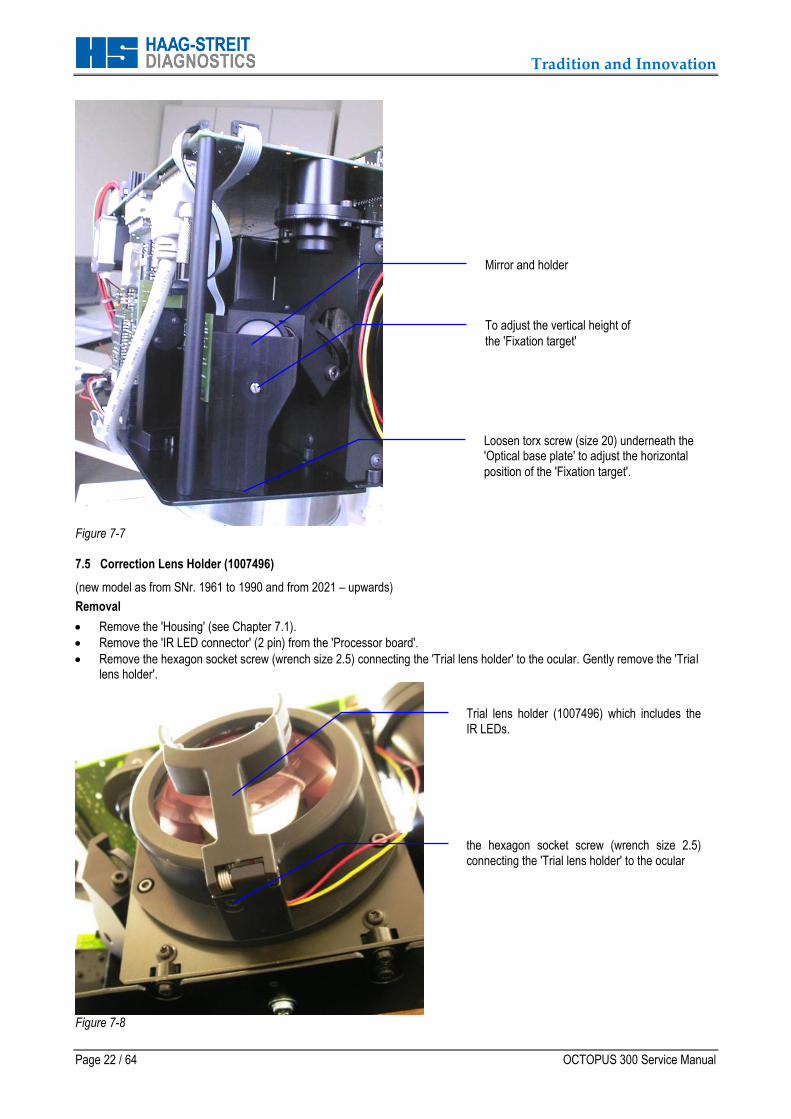
Figure 7-7
7.5 Correction Lens Holder (1007496)
(new model as from SNr. 1961 to 1990 and from 2021 – upwards)
Removal
Remove the 'Housing' (see Chapter 7.1).
Remove the 'IR LED connector' (2 pin) from the 'Processor board'.
Remove the hexagon socket screw (wrench size 2.5) connecting the 'Trial lens holder' to the ocular. Gently remove the 'Trial lens holder'.
Figure 7-8
To adjust the vertical height of
the 'Fixation target'
Loosen torx screw (size 20) underneath the 'Optical base plate' to adjust the horizontal
position of the 'Fixation target'.
Trial lens holder (1007496) which includes the IR LEDs.
the hexagon socket screw (wrench size 2.5) connecting the 'Trial lens holder' to the ocular
Mirror and holder
Tradition and Innovation
OCTOPUS 300 Service Manual Page 23 / 64
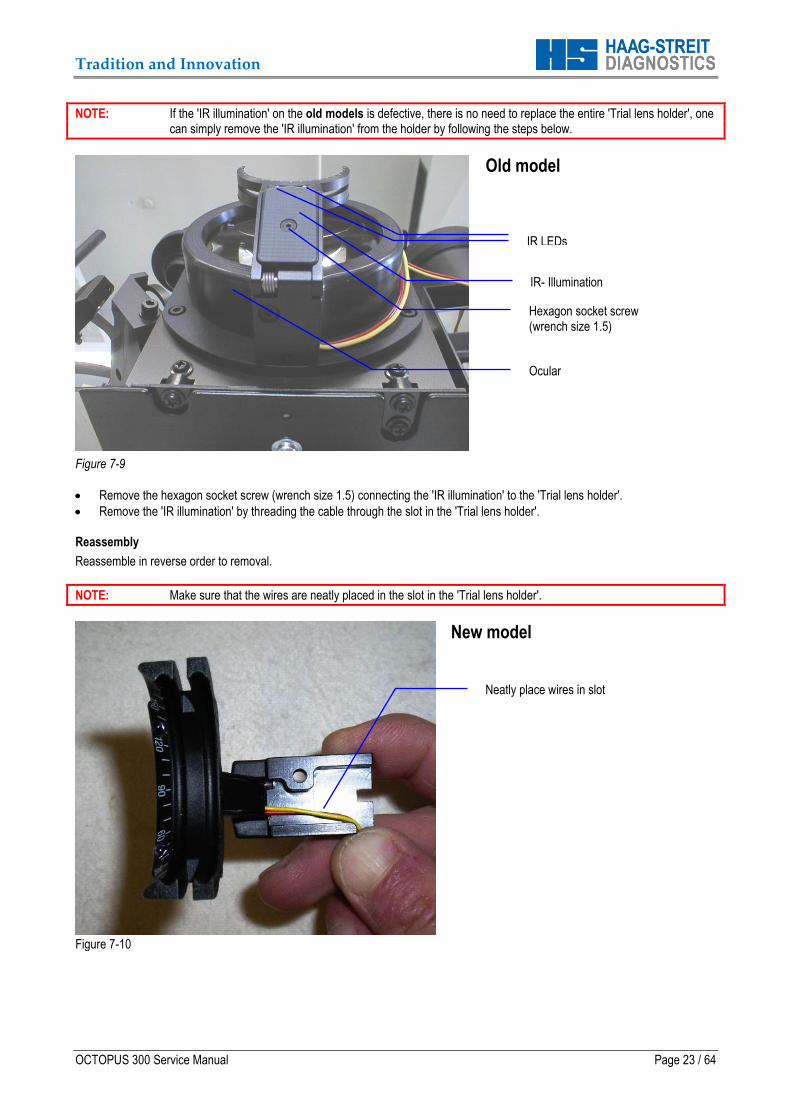
NOTE: If the 'IR illumination' on the old models is defective, there is no need to replace the entire 'Trial lens holder', one can simply remove the 'IR illumination' from the holder by following the steps below.
Figure 7-9
Old model
Remove the hexagon socket screw (wrench size 1.5) connecting the 'IR illumination' to the 'Trial lens holder'.
Remove the 'IR illumination' by threading the cable through the slot in the 'Trial lens holder'. Reassembly
Reassemble in reverse order to removal.
NOTE: Make sure that the wires are neatly placed in the slot in the 'Trial lens holder'.
Figure 7-10
New model
Hexagon socket screw (wrench size 1.5)
IR LEDs
Ocular
IR- Illumination
Neatly place wires in slot
Tradition and Innovation
Page 24 / 64 OCTOPUS 300 Service Manual
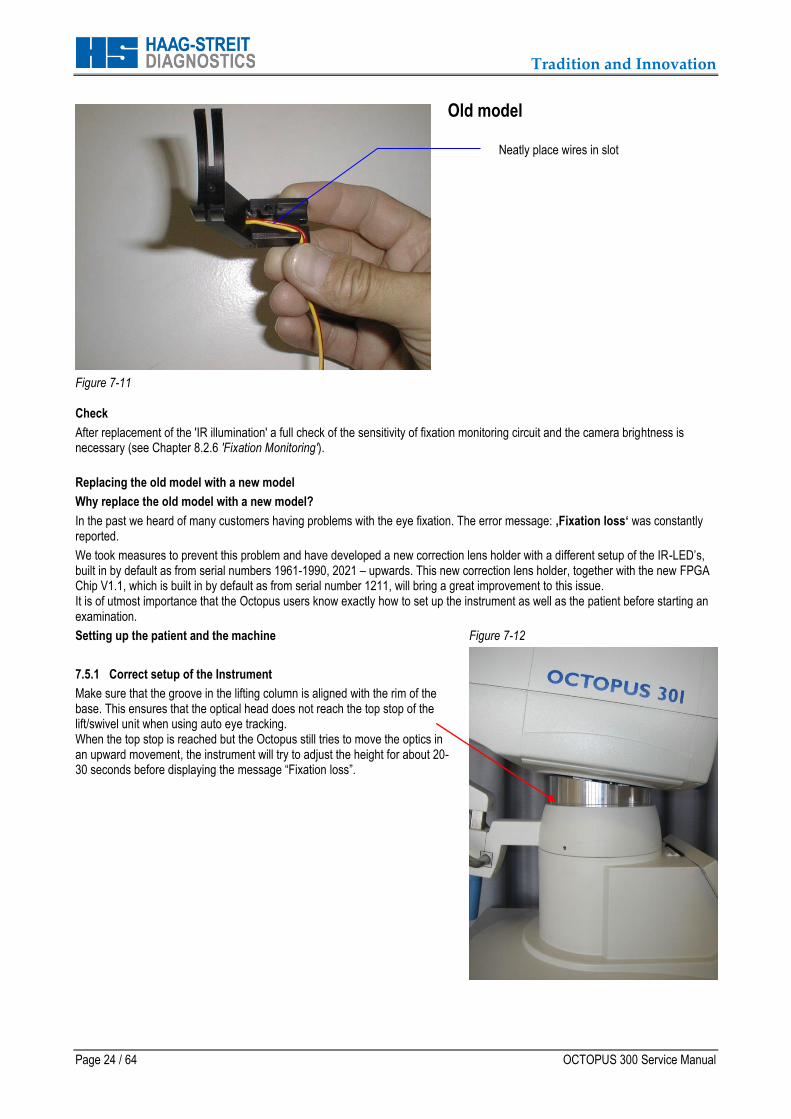
Figure 7-11
Old model
Check
After replacement of the 'IR illumination' a full check of the sensitivity of fixation monitoring circuit and the camera brightness is necessary (see Chapter 8.2.6 'Fixation Monitoring').
Replacing the old model with a new model
Why replace the old model with a new model?
In the past we heard of many customers having problems with the eye fixation. The error message: ‚Fixation loss‘ was constantly reported.
We took measures to prevent this problem and have developed a new correction lens holder with a different setup of the IR-LED’s, built in by default as from serial numbers 1961-1990, 2021 – upwards. This new correction lens holder, together with the new FPGA Chip V1.1, which is built in by default as from serial number 1211, will bring a great improvement to this issue. It is of utmost importance that the Octopus users know exactly how to set up the instrument as well as the patient before starting an examination.
Setting up the patient and the machine
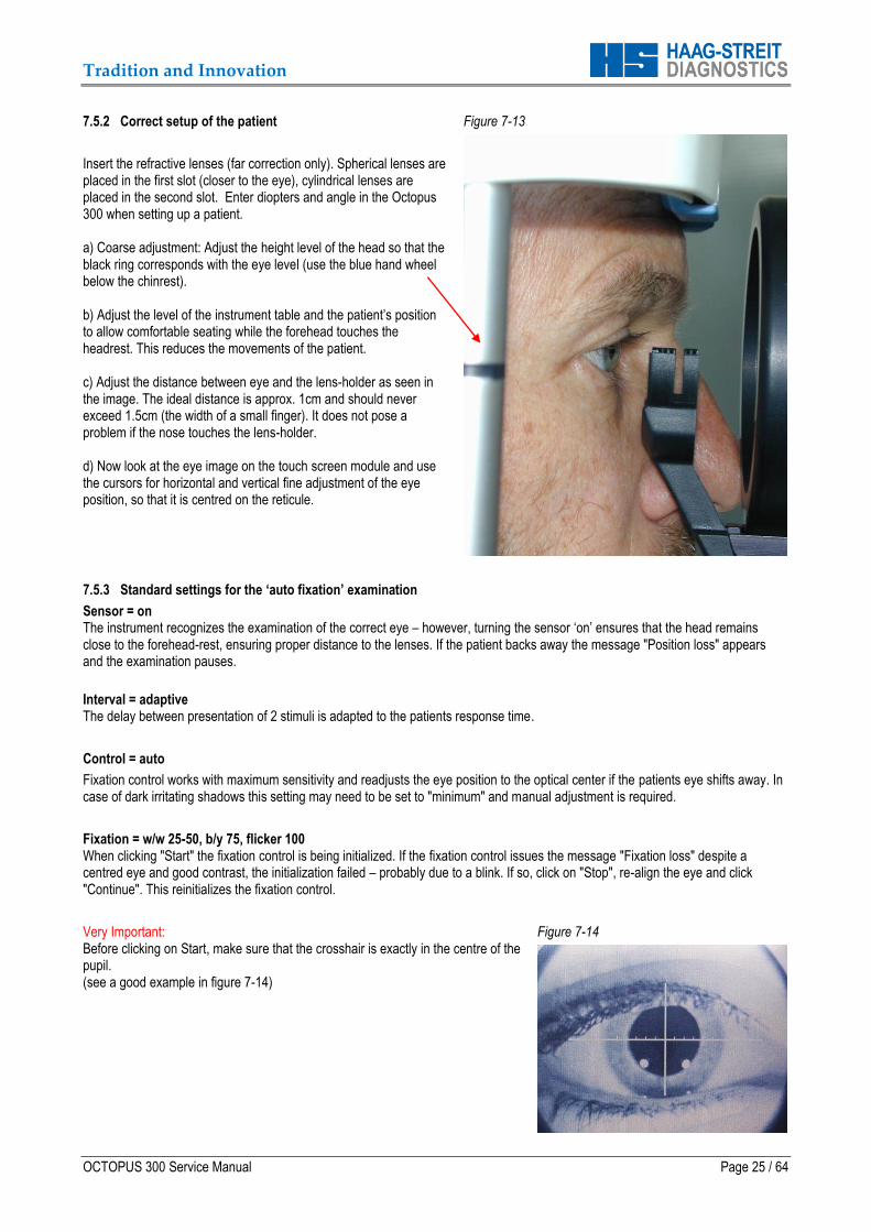
7.5.1 Correct setup of the Instrument
Make sure that the groove in the lifting column is aligned with the rim of the base. This ensures that the optical head does not reach the top stop of the lift/swivel unit when using auto eye tracking. When the top stop is reached but the Octopus still tries to move the optics in an upward movement, the instrument will try to adjust the height for about 20-30 seconds before displaying the message “Fixation loss”.
Figure 7-12
Neatly place wires in slot
Tradition and Innovation
OCTOPUS 300 Service Manual Page 25 / 64
7.5.2 Correct setup of the patient
Insert the refractive lenses (far correction only). Spherical lenses are placed in the first slot (closer to the eye), cylindrical lenses are placed in the second slot. Enter diopters and angle in the Octopus 300 when setting up a patient. a) Coarse adjustment: Adjust the height level of the head so that the black ring corresponds with the eye level (use the blue hand wheel below the chinrest). b) Adjust the level of the instrument table and the patient’s position to allow comfortable seating while the forehead touches the headrest. This reduces the movements of the patient. c) Adjust the distance between eye and the lens-holder as seen in the image. The ideal distance is approx. 1cm and should never exceed 1.5cm (the width of a small finger). It does not pose a problem if the nose touches the lens-holder. d) Now look at the eye image on the touch screen module and use the cursors for horizontal and vertical fine adjustment of the eye position, so that it is centred on the reticule.
Figure 7-13
7.5.3 Standard settings for the ‘auto fixation’ examination
Sensor = on The instrument recognizes the examination of the correct eye – however, turning the sensor ‘on’ ensures that the head remains close to the forehead-rest, ensuring proper distance to the lenses. If the patient backs away the message "Position loss" appears and the examination pauses.
Interval = adaptive The delay between presentation of 2 stimuli is adapted to the patients response time.
Control = auto
Fixation control works with maximum sensitivity and readjusts the eye position to the optical center if the patients eye shifts away. In case of dark irritating shadows this setting may need to be set to "minimum" and manual adjustment is required.
Fixation = w/w 25-50, b/y 75, flicker 100 When clicking "Start" the fixation control is being initialized. If the fixation control issues the message "Fixation loss" despite a centred eye and good contrast, the initialization failed – probably due to a blink. If so, click on "Stop", re-align the eye and click "Continue". This reinitializes the fixation control.
Very Important: Before clicking on Start, make sure that the crosshair is exactly in the centre of the pupil. (see a good example in figure 7-14)
Figure 7-14

Tradition and Innovation
Page 26 / 64 OCTOPUS 300 Service Manual
7.5.4 Correction lenses Strong correction lenses may also cause the error message “fixation loss”. Due to the refraction of the lenses, the Octopus 300 can not properly identify the pupil and thus reports that it has lost fixation. In cases where a strong correction lens is used the operator may have to set the fixation control to minimum.
7.5.5 New correction lens holder Part Number: 1007496
The new version of the correction lens holder, which was have developed has a different arrangement of the IR-LEDs for better illumination of the patient eye. Tests confirmed that this improved illumination of the eye enhances the fixation control. The new correction lens holder is built in by standard as from serial numbers: 1961-1990, 2021 – upwards. We recommend replacing the correction lens holder in any older unit when the customer complains about the functionality of the auto eye tracking. In instruments with serial number below 1211, the FPGA chip also needs to be replaced to assure proper functioning of the fixation control. Please Note: All the flash software versions were programmed to work with the old correction lens holder. You may have already noticed that even when one manually adjusts the IR brightness level (video) in the examination window, the Octopus will set this level back to 70 when pressing start.
The above mentioned was deliberately built in by our software developers because tests have shown that this is the proper setting for most eyes when using the old correction lens holder.
7.6 Background Module, Lamp house (1802247)
The 'Background module' is fitted to the 'Base plate' at a 6° angle. For easy realignment, mark the original position of the 'Background module' on the 'Base plate' with a pencil before removal.
NOTE: Removal should never be necessary.
Figure 7-15
7.6.1 Background Illumination Board (1802220)
Background module, lamp house

Tradition and Innovation
OCTOPUS 300 Service Manual Page 27 / 64
Removal
Remove the 'Housing' (see Chapter 7.1).
Remove the 'Illumination connector' (4 pin) from the 'Background illumination board'.
Remove the two nuts holding down the cover of the 'Background LED module'.
Figure 7-16
Remove the covering.
Remove the two springs which hold down the covering in the correct position.
Remove the 'Background illumination board' and place it on a surface with static discharge protection – handle with great care. Check
After replacing the 'Background illumination board' it is important to carry out the background intensity (see Chapter 8.2.5). 7.7 Brightness Regulator Module (1802248)
NOTE: Never replace the 'Sensor board' (Part No. 1802210) on its own. It is important to exchange the complete 'Brightness regulator module'. The reason for this is that the 'Sensor board' must be mounted on the 'Mounting plate' in a predefined and checked position so that the two sensors are situated in the right place for calibration.
After replacement of the 'Brightness regulator module' the calibration parameters belonging to that specific brightness regulator module, have to be entered into the system. Please refer to Chapter 7.7.1 'Entering Calibration Parameters'.
Removal
Remove the 'Housing' (see Chapter 7.1).
Remove the 'Flat cable connector', marked with 'Sensor' on the 'Processor board' (8 pin).
Remove the 2 torx screws (size 20) from underneath the 'Base plate' of the 'Optical unit'.
Figure 7-17
Torx screw (screwdriver size 20), holding the 'Fixation target'
Two nuts holding the cover of the Background LED module
Remove two torx screws (screwdriver size 20) to remove the 'Brightness
regulator module'

Tradition and Innovation
Page 28 / 64 OCTOPUS 300 Service Manual
Gently move the sliding device on the 'Stimulus projector unit' towards the left (for more details about the 'Stimulus projector unit' refer to Chapter 7.8).
Gently slide the 'Brightness regulator module' out (underneath the plate between the mirror and the 'Sensor board') towards the 'Stimulus projector unit' (operator side). Take care not to touch the 'Beam splitter' which is situated to the left of the 'Brightness regulator module' (looking from the operator side).
Place the 'Brightness regulator module' on a clean surface.
NOTE: If the 'Beam splitter' is scratched, it must be replaced.
Reassembly
Reassemble in reverse order to removal.
Check
Enter 'Service programs' to run the 'General test' to verify faultless operation.
Run a patient examination.
Tradition and Innovation
OCTOPUS 300 Service Manual Page 29 / 64
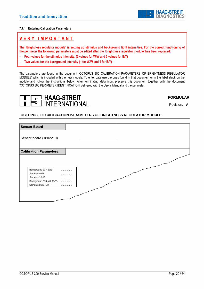
7.7.1 Entering Calibration Parameters
V E R Y I M P O R T A N T
The ‘Brightness regulator module’ is setting up stimulus and background light intensities. For the correct functioning of the perimeter the following parameters must be edited after the ‘Brightness regulator module’ has been replaced:
Four values for the stimulus intensity. (2 values for W/W and 2 values for B/Y)
Two values for the background intensity (1 for W/W and 1 for B/Y)
The parameters are found in the document 'OCTOPUS 300 CALIBRATION PARAMETERS OF BRIGHTNESS REGULATOR MODULE' which is included with the new module. To enter data use the ones found in that document or in the label stuck on the module and follow the instructions below. After terminating data input preserve this document together with the document 'OCTOPUS 300 PERIMETER IDENTIFICATION' delivered with the User's Manual and the perimeter.
FORMULAR
Revision: A
OCTOPUS 300 CALIBRATION PARAMETERS OF BRIGHTNESS REGULATOR MODULE
Sensor Board
Sensor board (1802210)
Calibration Parameters
Background 31.4 asb .................
Stimulus 0 dB .................
Stimulus 20 dB .................
Background 314 asb (B/Y) .................
Stimulus 0 dB (B/Y) .................
Stimulus 20 dB (B/Y) .................
Tradition and Innovation
Page 30 / 64 OCTOPUS 300 Service Manual
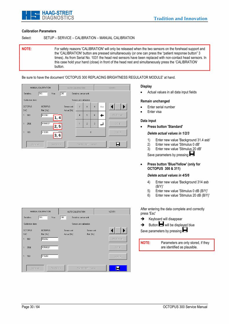
Calibration Parameters
Select: SETUP – SERVICE – CALIBRATION – MANUAL CALIBRATION
NOTE: For safety reasons 'CALIBRATION' will only be released when the two sensors on the forehead support and the 'CALIBRATION' button are pressed simultaneously (or one can press the “patient response button” 3 times). As from Serial No. 1031 the head rest sensors have been replaced with non-contact head sensors. In this case hold your hand (close) in front of the head rest and simultaneously press the ‘CALIBRATION‘ button.
Be sure to have the document 'OCTOPUS 300 REPLACING BRIGHTNESS REGULATOR MODULE' at hand.
Display
Actual values in all data input fields
Remain unchanged
Enter serial number
Enter visa
Data input
Press button 'Standard'
Delete actual values in 1/2/3
1) Enter new value 'Background 31.4 asb' 2) Enter new value 'Stimulus 0 dB' 3) Enter new value 'Stimulus 20 dB'
Save parameters by pressing
Press button 'Blue/Yellow' (only for OCTOPUS 300 & 311)
Delete actual values in 4/5/6
4) Enter new value 'Background 314 asb (B/Y)'
5) Enter new value 'Stimulus 0 dB (B/Y)' 6) Enter new value 'Stimulus 20 dB (B/Y)'
After entering the data complete and correctly press 'Esc'
Keyboard will disappear
Button will be displayed blue
Save parameters by pressing
NOTE: Parameters are only stored, if they are identified as plausible.
1, 4
2, 5
3, 6
Tradition and Innovation
OCTOPUS 300 Service Manual Page 31 / 64
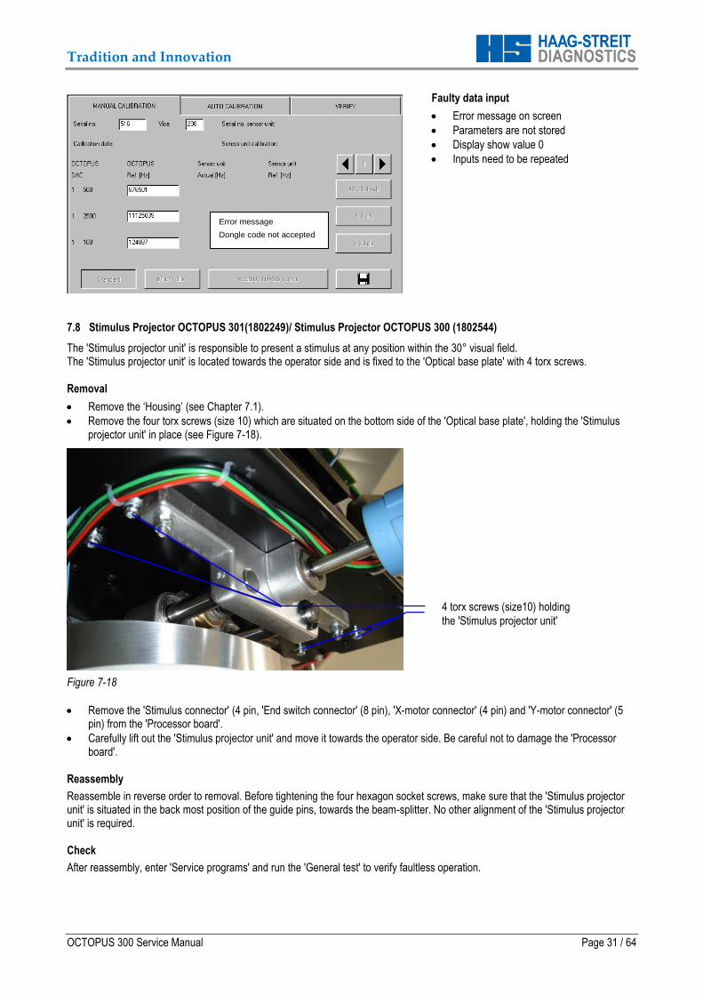
Faulty data input
Error message on screen
Parameters are not stored
Display show value 0
Inputs need to be repeated
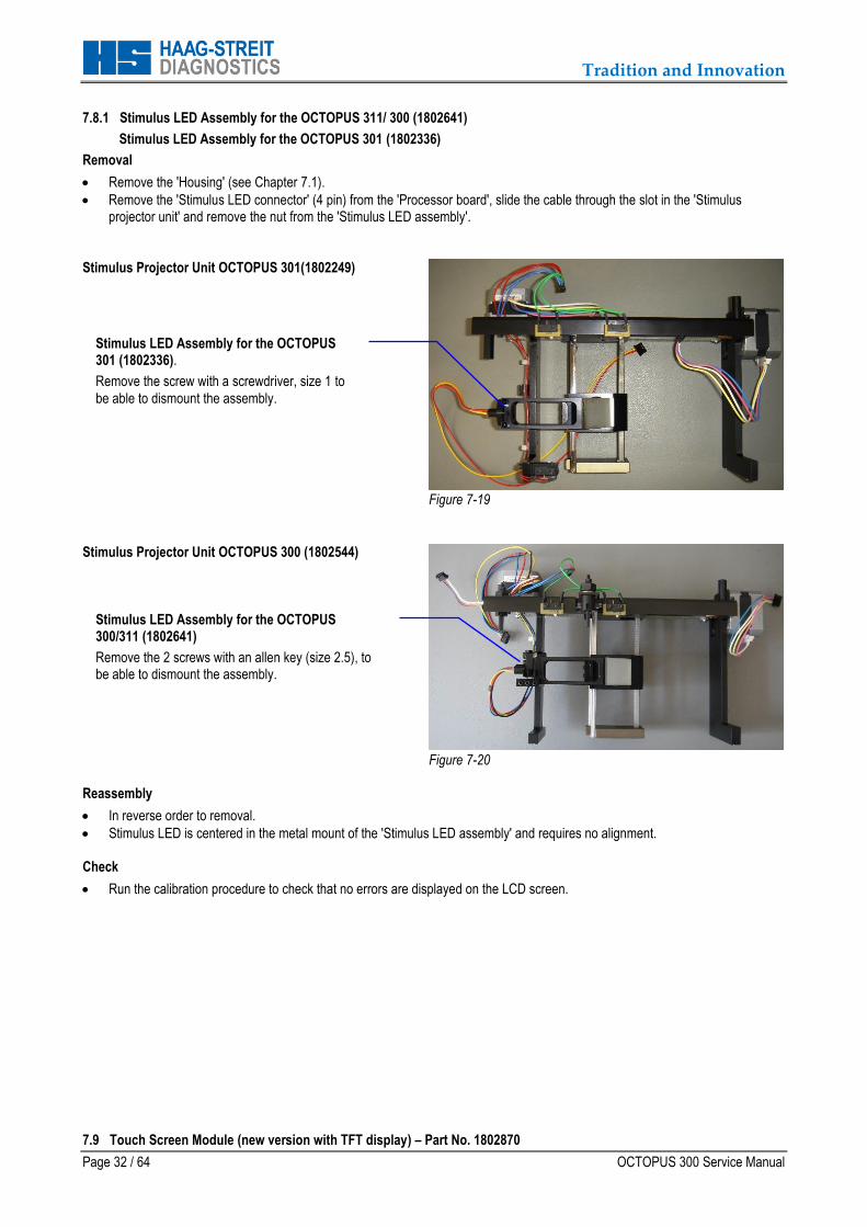
7.8 Stimulus Projector OCTOPUS 301(1802249)/ Stimulus Projector OCTOPUS 300 (1802544)
The 'Stimulus projector unit' is responsible to present a stimulus at any position within the 30° visual field. The 'Stimulus projector unit' is located towards the operator side and is fixed to the 'Optical base plate' with 4 torx screws. Removal
Remove the ‘Housing’ (see Chapter 7.1).
Remove the four torx screws (size 10) which are situated on the bottom side of the 'Optical base plate', holding the 'Stimulus projector unit' in place (see Figure 7-18).
Figure 7-18
Remove the 'Stimulus connector' (4 pin, 'End switch connector' (8 pin), 'X-motor connector' (4 pin) and 'Y-motor connector' (5 pin) from the 'Processor board'.
Carefully lift out the 'Stimulus projector unit' and move it towards the operator side. Be careful not to damage the 'Processor board'.
Reassembly
Reassemble in reverse order to removal. Before tightening the four hexagon socket screws, make sure that the 'Stimulus projector unit' is situated in the back most position of the guide pins, towards the beam-splitter. No other alignment of the 'Stimulus projector unit' is required. Check
After reassembly, enter 'Service programs' and run the 'General test' to verify faultless operation.
4 torx screws (size10) holding
the 'Stimulus projector unit'
Error message
Dongle code not accepted
Tradition and Innovation
Page 32 / 64 OCTOPUS 300 Service Manual
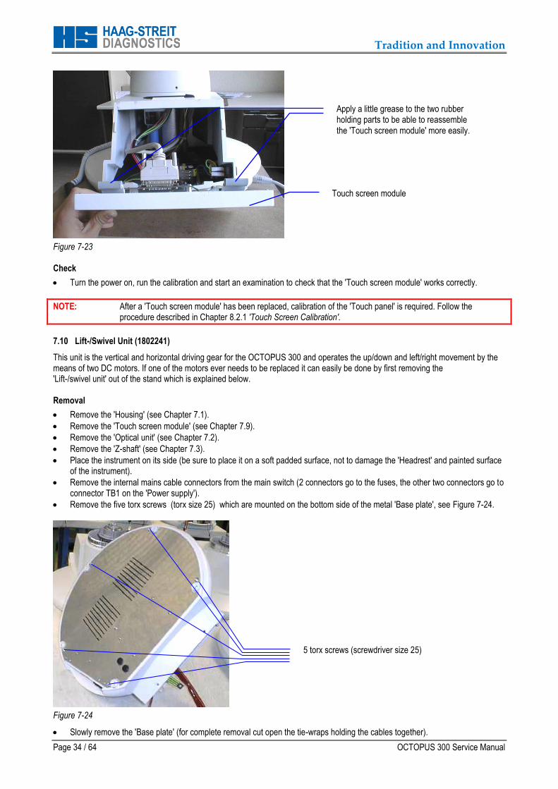
7.8.1 Stimulus LED Assembly for the OCTOPUS 311/ 300 (1802641)
Stimulus LED Assembly for the OCTOPUS 301 (1802336)
Removal
Remove the 'Housing' (see Chapter 7.1).
Remove the 'Stimulus LED connector' (4 pin) from the 'Processor board', slide the cable through the slot in the 'Stimulus projector unit' and remove the nut from the 'Stimulus LED assembly'.
Stimulus Projector Unit OCTOPUS 301(1802249)
Figure 7-19
Stimulus Projector Unit OCTOPUS 300 (1802544)
Figure 7-20
Reassembly
In reverse order to removal.
Stimulus LED is centered in the metal mount of the 'Stimulus LED assembly' and requires no alignment. Check
Run the calibration procedure to check that no errors are displayed on the LCD screen. 7.9 Touch Screen Module (new version with TFT display) – Part No. 1802870
Stimulus LED Assembly for the OCTOPUS 301 (1802336).
Remove the screw with a screwdriver, size 1 to
be able to dismount the assembly.
Stimulus LED Assembly for the OCTOPUS 300/311 (1802641)
Remove the 2 screws with an allen key (size 2.5), to be able to dismount the assembly.

Tradition and Innovation
OCTOPUS 300 Service Manual Page 33 / 64
(Regarding the modification from the old touch screen module to the new one, please refer to service news issues numbers 117 and 118 – available from the customer support centre at Haag-Streit AG)
The 'Touch screen module' is located towards the operator side of the instrument. Removal
Remove the two torx screws (size 20) on the bottom side of the 'Touch screen module'. See Figure 7-21.
Figure 7-21
Carefully lift up the bottom part of the 'Touch screen module' about 15mm, then push from the top part of the 'Touch screen module' in a downward movement to be able to remove it from the stand.
Remove the hexagon socket screw (wrench size 3) holding the grounding cable to the 'Touch screen module', remove both the 2 pin and 50 pin connectors from the 'Touch screen module'.
The 'Touch screen module' can now be removed completely. Place it on a clean, flat surface.
Figure 7-22
Touch screen module with TFT display (as from SNr. 2291) Part No. 1802870
Reassembly
In reverse order to removal.
NOTE: If it is difficult to slide in the top part of the 'Touch screen module' it is recommended to apply a little grease to the two rubber holding parts.
Remove 2 torx screws (screwdriver size 20)
Touch screen module
Backlight inverter for TFT display - Part no.
1802876
Tradition and Innovation
Page 34 / 64 OCTOPUS 300 Service Manual
Figure 7-23
Check
Turn the power on, run the calibration and start an examination to check that the 'Touch screen module' works correctly.
NOTE: After a 'Touch screen module' has been replaced, calibration of the 'Touch panel' is required. Follow the procedure described in Chapter 8.2.1 'Touch Screen Calibration'.
7.10 Lift-/Swivel Unit (1802241)
This unit is the vertical and horizontal driving gear for the OCTOPUS 300 and operates the up/down and left/right movement by the means of two DC motors. If one of the motors ever needs to be replaced it can easily be done by first removing the 'Lift-/swivel unit' out of the stand which is explained below. Removal
Remove the 'Housing' (see Chapter 7.1).
Remove the 'Touch screen module' (see Chapter 7.9).
Remove the 'Optical unit' (see Chapter 7.2).
Remove the 'Z-shaft' (see Chapter 7.3).
Place the instrument on its side (be sure to place it on a soft padded surface, not to damage the 'Headrest' and painted surface of the instrument).
Remove the internal mains cable connectors from the main switch (2 connectors go to the fuses, the other two connectors go to connector TB1 on the 'Power supply').
Remove the five torx screws (torx size 25) which are mounted on the bottom side of the metal 'Base plate', see Figure 7-24.
Figure 7-24
Slowly remove the 'Base plate' (for complete removal cut open the tie-wraps holding the cables together).
Apply a little grease to the two rubber holding parts to be able to reassemble the 'Touch screen module' more easily.
Touch screen module
5 torx screws (screwdriver size 25)
Tradition and Innovation
OCTOPUS 300 Service Manual Page 35 / 64
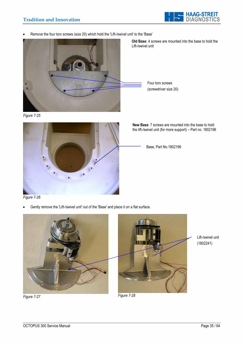
Remove the four torx screws (size 20) which hold the 'Lift-/swivel unit' to the 'Base'
Figure 7-25
Old Base: 4 screws are mounted into the base to hold the Lift-/swivel unit
Figure 7-26
New Base: 7 screws are mounted into the base to hold the lift-/swivel unit (for more support) – Part no. 1802196
Gently remove the 'Lift-/swivel unit' out of the 'Base' and place it on a flat surface.
Figure 7-27
Figure 7-28
Four torx screws
(screwdriver size 20)
Base, Part No.1802196
Lift-/swivel unit
(1802241)
Tradition and Innovation
Page 36 / 64 OCTOPUS 300 Service Manual
Reassembly In reverse order to removal. Check
After reassembly, enter the 'Service programs' and run the 'General test' to check that the instrument is fully functional. Special notice should be made to the movement of the 'Lift-/swivel unit'. 7.11 Headrest Assembly
The 'Headrest assembly' is situated on the patient side of the instrument. It comprises three main parts.
The 'Swivel ring' enables to turn the headrest around the column of the instrument and to seat the patient in any position (see Chapter 3.3 'Installation'). The 'Swivel ring' includes the 'Switcher board' (1802745).
The ‘Forehead support with non-contact head sensors (1802751 for serial No. ≥ 1031). The sensors on the forehead support are to detect whether the patient is seated correctly and also to detect which eye is being examined.
The 'Chin rest assembly'. Removal
The complete 'Headrest assembly' can be removed by doing the following steps.
Remove the 'Housing (see Chapter 7.1).
Remove the 'Optical unit' (see Chapter 7.2).
Remove the 'Z-shaft' (see Chapter 7.3).
Remove the 'Patient response button'
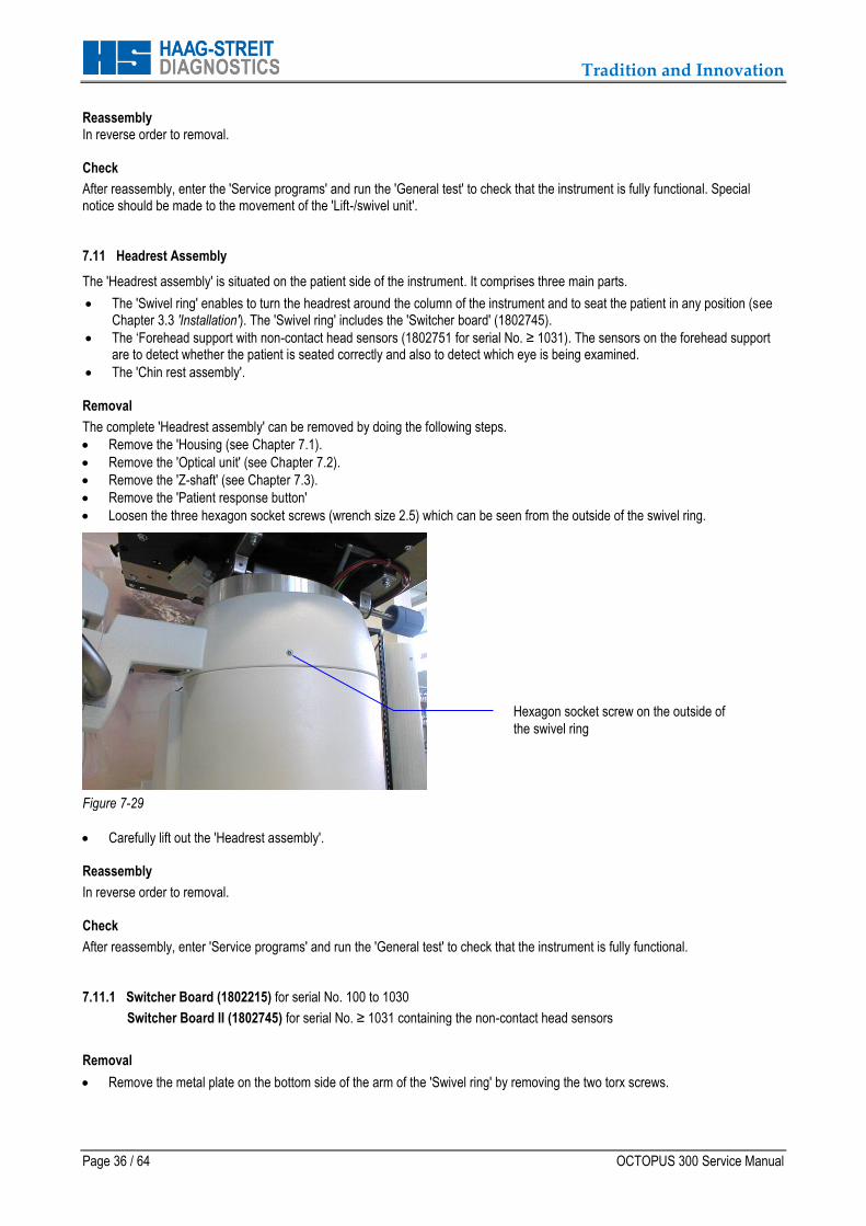
Loosen the three hexagon socket screws (wrench size 2.5) which can be seen from the outside of the swivel ring.
Figure 7-29
Carefully lift out the 'Headrest assembly'. Reassembly
In reverse order to removal. Check
After reassembly, enter 'Service programs' and run the 'General test' to check that the instrument is fully functional. 7.11.1 Switcher Board (1802215) for serial No. 100 to 1030
Switcher Board II (1802745) for serial No. ≥ 1031 containing the non-contact head sensors
Removal
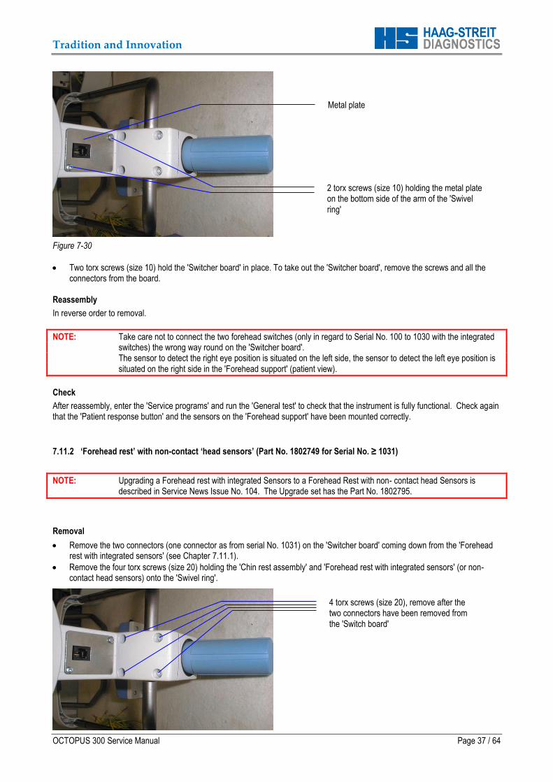
Remove the metal plate on the bottom side of the arm of the 'Swivel ring' by removing the two torx screws.
Hexagon socket screw on the outside of
the swivel ring
Tradition and Innovation
OCTOPUS 300 Service Manual Page 37 / 64
Figure 7-30
Two torx screws (size 10) hold the 'Switcher board' in place. To take out the 'Switcher board', remove the screws and all the connectors from the board.
Reassembly
In reverse order to removal.
NOTE: Take care not to connect the two forehead switches (only in regard to Serial No. 100 to 1030 with the integrated switches) the wrong way round on the 'Switcher board'. The sensor to detect the right eye position is situated on the left side, the sensor to detect the left eye position is situated on the right side in the 'Forehead support' (patient view).
Check
After reassembly, enter the 'Service programs' and run the 'General test' to check that the instrument is fully functional. Check again that the 'Patient response button' and the sensors on the 'Forehead support' have been mounted correctly.
7.11.2 ‘Forehead rest’ with non-contact ‘head sensors’ (Part No. 1802749 for Serial No. ≥ 1031)
NOTE: Upgrading a Forehead rest with integrated Sensors to a Forehead Rest with non- contact head Sensors is described in Service News Issue No. 104. The Upgrade set has the Part No. 1802795.
Removal
Remove the two connectors (one connector as from serial No. 1031) on the 'Switcher board' coming down from the 'Forehead rest with integrated sensors' (see Chapter 7.11.1).
Remove the four torx screws (size 20) holding the 'Chin rest assembly' and 'Forehead rest with integrated sensors' (or non-contact head sensors) onto the 'Swivel ring'.
2 torx screws (size 10) holding the metal plate on the bottom side of the arm of the 'Swivel ring'
Metal plate
4 torx screws (size 20), remove after the two connectors have been removed from the 'Switch board'
Tradition and Innovation
Page 38 / 64 OCTOPUS 300 Service Manual
Figure 7-31
Both the 'Chin rest assembly' and the 'Forehead rest with integrated sensors' (or non-contact head sensors) can simply be pulled out and then be placed on a flat, scratch-free surface.
NOTE: If the sensors are damaged, (only in regard to Serial No. 100 to 1030 with the integrated sensors) we recommend to replace the whole 'Forehead rest with integrated sensors'.
Reassembly
In reverse order to removal
NOTE: Check that the connectors on the 'Switcher board' have been plugged in the correct connector (only in regard to Serial No. 100 to 1030 with the integrated sensors).
Check
After reassembly, enter the 'Service programs' to test the Patient Response Button and the 'Forehead rest with integrated sensors' (Forehead Rest with non-contact Head Sensors), see Chapter 8.2.7 'Checking In- and Outputs’.
7.12 Power Supply (1802199)
The 'Power supply' is situated on the 'Base plate' inside the 'Base' of the instrument Removal
Remove the 'Touch screen module' (see Chapter 7.9).
Remove all connectors from the 'Power supply'.
Remove the 4 torx screws (size 10) holding the 'Power supply' down onto the 'Base plate' and remove the 'Power supply'. Reassembly
In reverse order to removal. Check
After reassembly, enter the 'Service programs' and run the 'General test' to check that the instrument is fully functional. 7.12.1 Fuses (1801326)
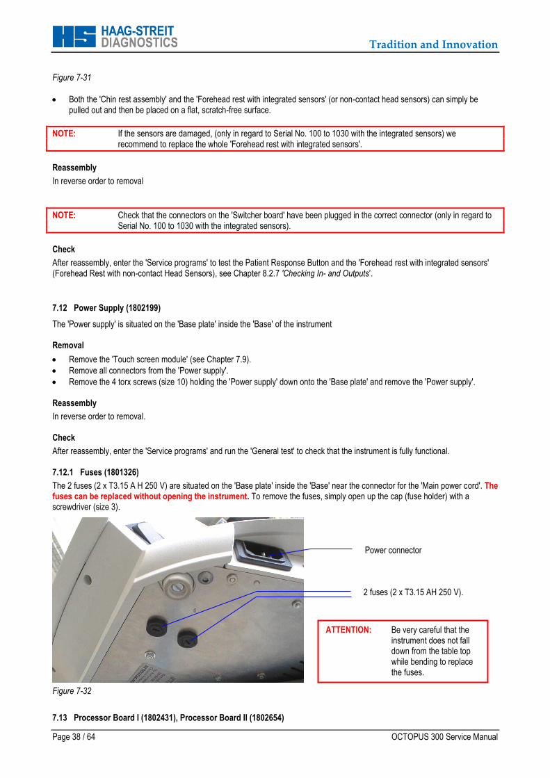
The 2 fuses (2 x T3.15 A H 250 V) are situated on the 'Base plate' inside the 'Base' near the connector for the 'Main power cord'. The fuses can be replaced without opening the instrument. To remove the fuses, simply open up the cap (fuse holder) with a screwdriver (size 3).
Figure 7-32
7.13 Processor Board I (1802431), Processor Board II (1802654)
2 fuses (2 x T3.15 AH 250 V).
Power connector
ATTENTION: Be very careful that the instrument does not fall down from the table top while bending to replace the fuses.

Tradition and Innovation
OCTOPUS 300 Service Manual Page 39 / 64
NOTE: Processor Board I can ONLY be used for the OCTOPUS 301 Perimeter Processor Board II can be used OCTOPUS 301 and 311/ 300 Perimeters
The 'Processor board' includes the CCD camera. It is the largest of all the electronic modules in the OCTOPUS 300 and is situated on top of the 'Optical unit'. All the connectors for the cables going to the sub-modules are marked on the 'Processor board'. The 'Main voltage cable' going from the 'Power supply' to the 'Processor board' is not marked but it is situated in the front right corner of the 'Processor board' (operator view). It is marked with a symbol '+'. Like all the other electronic boards it is important to protect the 'Processor board' from any static electricity and accidental discharge of the 'Lithium battery'. When storing keep it in a static shielding bag. If the 'Processor board' is defective, replace with a new one. To remove or change a board follow the steps described below.
IMPORTANT: After replacing the 'Processor board' some parameters have to be reentered into the system. Please refer to Chapter 7.13.1 ‘Entering Parameters’
Removal
Remove 'Housing top' (see Chapter 7.1).
Remove all connectors from the 'Processor board'
Remove the 'SIM Flash module' (see Chapter 7.14.1).
Remove the 'SDRAM module' (see Chapter 0).
Remove the six Philips screws which hold down the 'Processor board' to the frame and camera lens.
Remove the 'Processor board' and store it in a static shielding bag.
Figure 7-33
Reassembly
Reassemble in reverse order to removal. Check
If replacing the ‘Processor board’, it is necessary to reenter all the parameters into the memory. Please refer to Chapter 7.13.1 ‘Entering Parameters’
Check that the focus of the camera is still correct. For correct positioning and focus, refer to Chapter 7.14.2 'Camera – Positioning and Focus'.
After reassembly, enter the 'Service programs' and run the 'General test' to check that the instrument is fully functional.
For a final check run a patient examination.
Processor board
LCD cable
Fixation target
Interface board
Swivel ring
SIM Flash module
Processor board

Tradition and Innovation
Page 40 / 64 OCTOPUS 300 Service Manual
7.13.1 Entering Parameters
V E R Y I M P O R T A N T
The data stored on the ‘Processor board’ is very important for the correct function of the perimeter.
The following parameters must be reentered after the ‘Processor board’ has been exchanged:
Serial-No. of the perimeter
Four values for the stimulus intensity (2 values for W/W and 2 values for B/Y)
Two values for the background intensity (1 for W/W and 1 for B/Y)
Complete dongle code
The parameters are found in the document 'OCTOPUS 300, 301 or 311 PERIMETER IDENTIFICATION'. This document is delivered together with the User's Manual and the perimeter. Use the data found in that document. If you can not find the document, please contact the OCTOPUS Service department at Haag-Streit AG.
The numbers in the instruction on the following page are examples and do not match with those of your system.
FORMULAR
Revision: A
OCTOPUS 300 PERIMETER IDENTIFICATION
OCTOPUS
Perimeter type 301 311 300
Serial number <SNr.>
Dongle code <Number-1> <Number-2> <Number-3>
Calibration Parameters
Frequency [Hz]
Background 31.4 asb <Value-1>
Stimulus 0 dB <Value-2>
Stimulus 20 dB <Value-3>
Background 314 asb (B/Y) <Value-4>
Stimulus 0 dB (B/Y) <Value-5>
Stimulus 20 dB (B/Y) <Value-6>
Tradition and Innovation
OCTOPUS 300 Service Manual Page 41 / 64
After the 'Processor board' and 'SIM Flash module' have been replaced, the data must be entered as described below.
Serial Number, Calibration Parameters
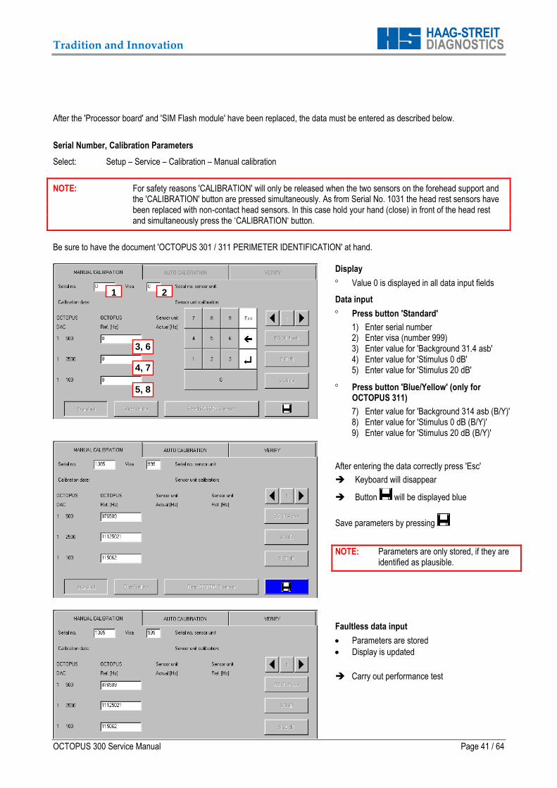
Select: Setup – Service – Calibration – Manual calibration
NOTE: For safety reasons 'CALIBRATION' will only be released when the two sensors on the forehead support and the 'CALIBRATION' button are pressed simultaneously. As from Serial No. 1031 the head rest sensors have been replaced with non-contact head sensors. In this case hold your hand (close) in front of the head rest and simultaneously press the ‘CALIBRATION‘ button.
Be sure to have the document 'OCTOPUS 301 / 311 PERIMETER IDENTIFICATION' at hand.
Display
Value 0 is displayed in all data input fields
Data input
Press button 'Standard'
1) Enter serial number 2) Enter visa (number 999) 3) Enter value for 'Background 31.4 asb' 4) Enter value for 'Stimulus 0 dB' 5) Enter value for 'Stimulus 20 dB'
Press button 'Blue/Yellow' (only for OCTOPUS 311)
7) Enter value for 'Background 314 asb (B/Y)' 8) Enter value for 'Stimulus 0 dB (B/Y)' 9) Enter value for 'Stimulus 20 dB (B/Y)'
After entering the data correctly press 'Esc'
Keyboard will disappear
Button will be displayed blue
Save parameters by pressing
NOTE: Parameters are only stored, if they are identified as plausible.
Faultless data input
Parameters are stored
Display is updated
Carry out performance test
1 2
3, 6
4, 7
5, 8
Tradition and Innovation
Page 42 / 64 OCTOPUS 300 Service Manual
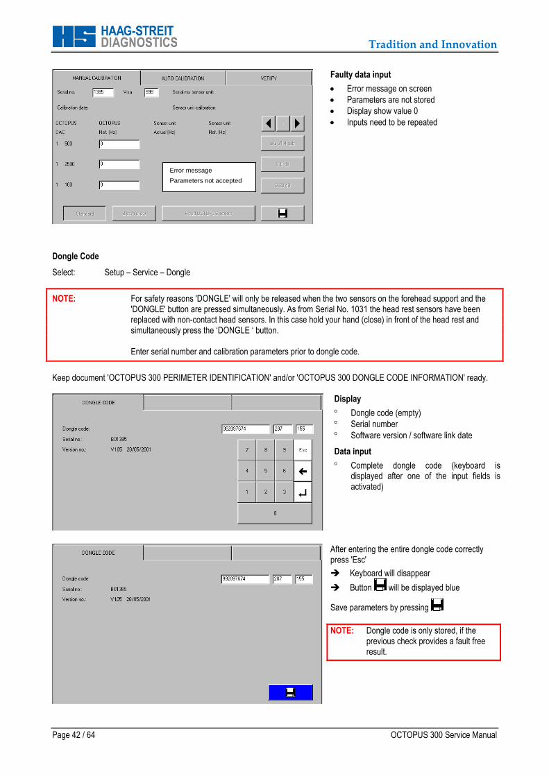
Faulty data input
Error message on screen
Parameters are not stored
Display show value 0
Inputs need to be repeated
Dongle Code
Select: Setup – Service – Dongle
NOTE: For safety reasons 'DONGLE' will only be released when the two sensors on the forehead support and the 'DONGLE' button are pressed simultaneously. As from Serial No. 1031 the head rest sensors have been replaced with non-contact head sensors. In this case hold your hand (close) in front of the head rest and simultaneously press the ‘DONGLE ‘ button.
Enter serial number and calibration parameters prior to dongle code.
Keep document 'OCTOPUS 300 PERIMETER IDENTIFICATION' and/or 'OCTOPUS 300 DONGLE CODE INFORMATION' ready.
Display
Dongle code (empty)
Serial number
Software version / software link date
Data input
Complete dongle code (keyboard is displayed after one of the input fields is activated)
After entering the entire dongle code correctly press 'Esc'
Keyboard will disappear
Button will be displayed blue
Save parameters by pressing
NOTE: Dongle code is only stored, if the previous check provides a fault free result.
Error message
Parameters not accepted

Tradition and Innovation
OCTOPUS 300 Service Manual Page 43 / 64
Faultless data input
Dongle code is stored
Display is updated
Program returns to main screen
Carry out performance test
Faulty data input
Error message on screen
Dongle code is not stored
Display 'Dongle code' remains empty
Inputs need to be repeated
7.13.2 Battery: old mounting version - 1802455 and new mounting version - 1820014
The 'Battery' (VARTA 3V/14h) is responsible that the setup parameters and the stored examination results are not lost after the perimeter has been switched off. The lithium battery has a life span of about 10 to 15 years. It is very seldom necessary to replace the 'Battery'. After switching the perimeter on, the voltage of the 'Battery' is automatically tested. If the voltage is too low, the error message ‘Battery low’ will be displayed on the screen. If the battery ever needs to be replaced, we recommend it to be replaced with an identical type or one, which has been tested and released by HAAG-STREIT AG.
Model type: VARTA CR AA 6117 Lithium-cell
Specification: 3V / 2Ah
Figure 7-34
Replacing the battery (old mounting version, clipped), Part No. 1802455
Turn off the Perimeter (Remove the power cord).
Remove 'Housing top' (see Chapter 7.1).
Cut and remove the tie wrap holding the battery in place.
Remove the old battery out of the battery holder.
Install new battery, check + and – side!
New battery must be fastened with a new tie wrap.
Replace the 'Housing top'
Power on the Perimeter and check that no error message is displayed.

Tradition and Innovation
Page 44 / 64 OCTOPUS 300 Service Manual
Figure 7-35
Replacing the battery (new mounting version, soldered), Part No. 1820014
Turn off the Perimeter (Remove the power cord).
Remove 'Housing top' (see Chapter 7.1).
Cut and remove the tie wrap holding the battery in place.
Unsolder the battery connection
Remove the old battery out of the battery holder.
Install new battery, check + and – side!
Solder new battery into place.
New battery must be fastened with a new tie wrap.
Replace the 'Housing top'
Power on the Perimeter and check that no error message is displayed.
7.13.3 Battery Upgrade
It is possible to modify the battery from the old mounting version to the new version by simply ordering the “Upgrade kit – battery”, Part No. 1820013.
The upgrade kit consists of a battery, two soldering pins and a tie-wrap.
Upgrades are only necessary in cases where the battery has a bad clipping contact.
7.14 SDRAM Module (1802152)
The 'SDRAM module' is mounted on top of the 'Processor board', see Figure 7-2. Removal
Remove 'Housing top' (see Chapter 7.1).
Remove 'SDRAM module'. Removal is the same procedure as for the 'SIM Flash module', see Chapter 7.14.1 'SIM Flash Module, Application Software (1802222)'.
Reassembly
Reassemble in reverse order to removal.
Check
After reassembly, enter the 'Service programs' and run the 'General test' to check that the instrument is fully functional. 7.14.1 SIM Flash Module, Application Software (1802222)
The 'SIM Flash module' is the memory for the application software and is mounted on top of the 'Processor board', see Figure 7-2. Removal
Remove 'Housing top' (see Chapter 7.1).
Tradition and Innovation
OCTOPUS 300 Service Manual Page 45 / 64
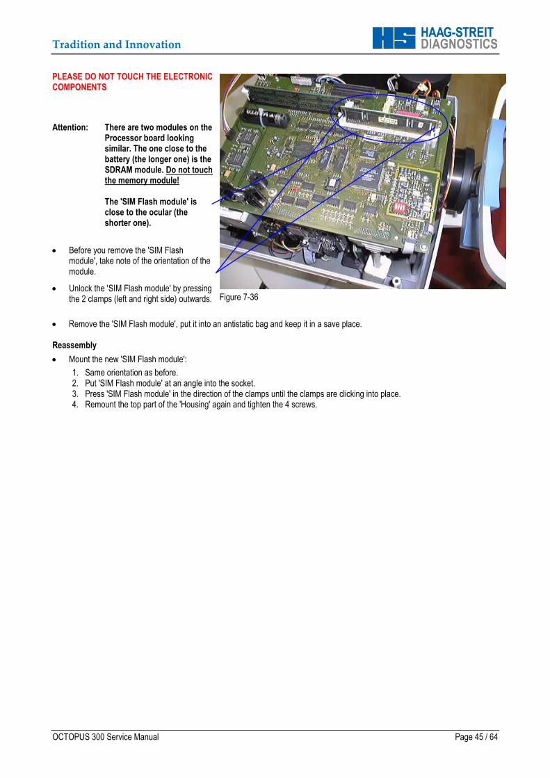
PLEASE DO NOT TOUCH THE ELECTRONIC COMPONENTS
Attention: There are two modules on the Processor board looking similar. The one close to the battery (the longer one) is the SDRAM module. Do not touch the memory module! The 'SIM Flash module' is close to the ocular (the shorter one).
Before you remove the 'SIM Flash module', take note of the orientation of the module.
Unlock the 'SIM Flash module' by pressing the 2 clamps (left and right side) outwards.
Figure 7-36
Remove the 'SIM Flash module', put it into an antistatic bag and keep it in a save place. Reassembly
Mount the new 'SIM Flash module':
1. Same orientation as before. 2. Put 'SIM Flash module' at an angle into the socket. 3. Press 'SIM Flash module' in the direction of the clamps until the clamps are clicking into place. 4. Remount the top part of the 'Housing' again and tighten the 4 screws.
Tradition and Innovation
Page 46 / 64 OCTOPUS 300 Service Manual
After changing the 'SIM Flash module' the memory has to be initialized - proceed as follows:
1. Press patient response button and keep it pressed. 2. Switch power on and keep 'Patient response button' pressed until 'Main screen' with OCTOPUS 300 logo is displayed. 3. Release 'Patient response button'.
Check
After reassembly, enter the 'Service programs' and run the 'General test' to check that the instrument is fully functional. 7.14.2 Camera – Positioning and Focus
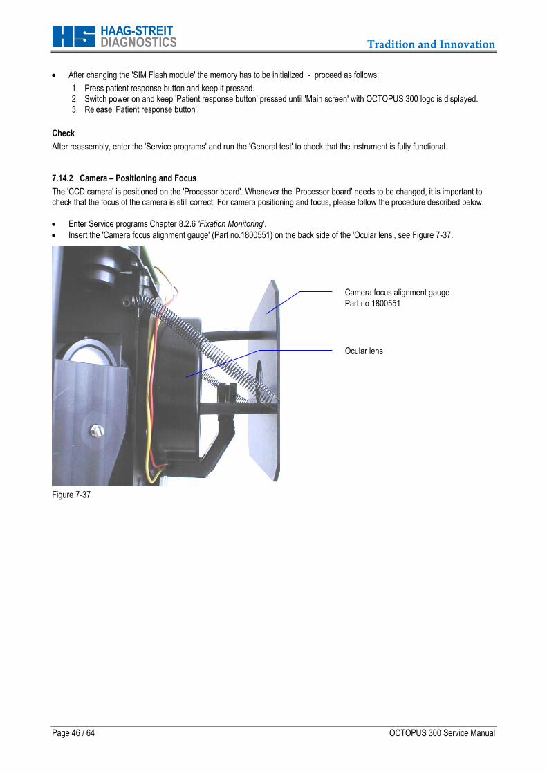
The 'CCD camera' is positioned on the 'Processor board'. Whenever the 'Processor board' needs to be changed, it is important to check that the focus of the camera is still correct. For camera positioning and focus, please follow the procedure described below.
Enter Service programs Chapter 8.2.6 'Fixation Monitoring'.
Insert the 'Camera focus alignment gauge' (Part no.1800551) on the back side of the 'Ocular lens', see Figure 7-37.
Figure 7-37
Camera focus alignment gauge
Part no 1800551
Ocular lens
Tradition and Innovation
OCTOPUS 300 Service Manual Page 47 / 64
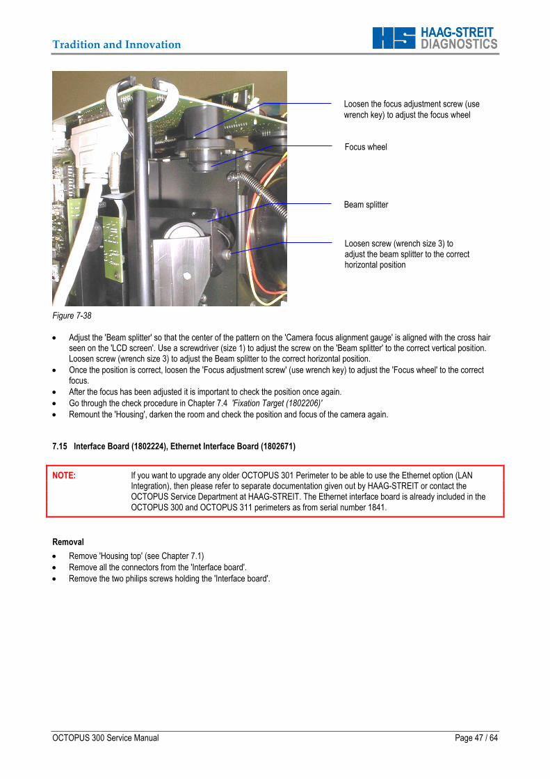
Figure 7-38
Adjust the 'Beam splitter' so that the center of the pattern on the 'Camera focus alignment gauge' is aligned with the cross hair seen on the 'LCD screen'. Use a screwdriver (size 1) to adjust the screw on the 'Beam splitter' to the correct vertical position. Loosen screw (wrench size 3) to adjust the Beam splitter to the correct horizontal position.
Once the position is correct, loosen the 'Focus adjustment screw' (use wrench key) to adjust the 'Focus wheel' to the correct focus.
After the focus has been adjusted it is important to check the position once again.
Go through the check procedure in Chapter 7.4 'Fixation Target (1802206)'
Remount the 'Housing', darken the room and check the position and focus of the camera again. 7.15 Interface Board (1802224), Ethernet Interface Board (1802671)
NOTE: If you want to upgrade any older OCTOPUS 301 Perimeter to be able to use the Ethernet option (LAN Integration), then please refer to separate documentation given out by HAAG-STREIT or contact the OCTOPUS Service Department at HAAG-STREIT. The Ethernet interface board is already included in the OCTOPUS 300 and OCTOPUS 311 perimeters as from serial number 1841.
Removal
Remove 'Housing top' (see Chapter 7.1)
Remove all the connectors from the 'Interface board'.
Remove the two philips screws holding the 'Interface board'.
Loosen the focus adjustment screw (use
wrench key) to adjust the focus wheel
Focus wheel
Loosen screw (wrench size 3) to adjust the beam splitter to the correct horizontal position
Beam splitter
Tradition and Innovation
Page 48 / 64 OCTOPUS 300 Service Manual
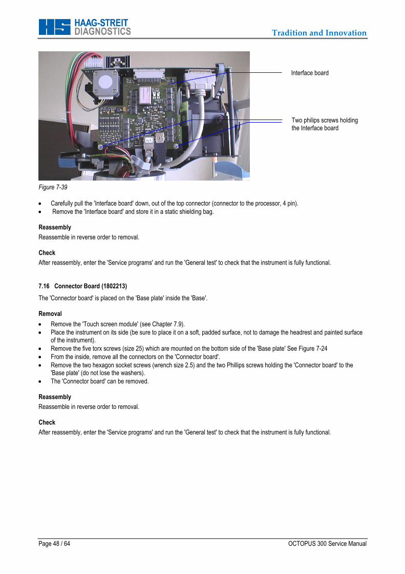
Figure 7-39
Carefully pull the 'Interface board' down, out of the top connector (connector to the processor, 4 pin).
Remove the 'Interface board' and store it in a static shielding bag. Reassembly
Reassemble in reverse order to removal. Check
After reassembly, enter the 'Service programs' and run the 'General test' to check that the instrument is fully functional. 7.16 Connector Board (1802213)
The 'Connector board' is placed on the 'Base plate' inside the 'Base'. Removal
Remove the 'Touch screen module' (see Chapter 7.9).
Place the instrument on its side (be sure to place it on a soft, padded surface, not to damage the headrest and painted surface of the instrument).
Remove the five torx screws (size 25) which are mounted on the bottom side of the 'Base plate' See Figure 7-24
From the inside, remove all the connectors on the 'Connector board'.
Remove the two hexagon socket screws (wrench size 2.5) and the two Phillips screws holding the 'Connector board' to the 'Base plate' (do not lose the washers).
The 'Connector board' can be removed. Reassembly
Reassemble in reverse order to removal. Check
After reassembly, enter the 'Service programs' and run the 'General test' to check that the instrument is fully functional.
Interface board
Two philips screws holding the Interface board
Tradition and Innovation
OCTOPUS 300 Service Manual Page 49 / 64
8 SERVICE PROGRAMS
Service programs integrated in the application software help
to check the perimeter
searching errors
carry out calibration
enter parameters 8.1 Subassembly Test
Select: SETUP – SERVICE – DIAGNOSTIC - SUBASSEMBLY
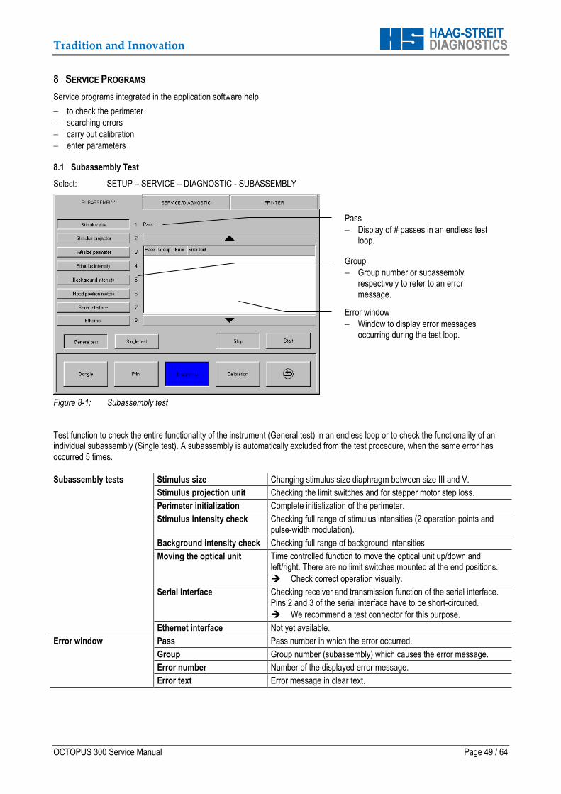
Figure 8-1: Subassembly test
Test function to check the entire functionality of the instrument (General test) in an endless loop or to check the functionality of an individual subassembly (Single test). A subassembly is automatically excluded from the test procedure, when the same error has occurred 5 times.
Subassembly tests Stimulus size Changing stimulus size diaphragm between size III and V.
Stimulus projection unit Checking the limit switches and for stepper motor step loss.
Perimeter initialization Complete initialization of the perimeter.
Stimulus intensity check Checking full range of stimulus intensities (2 operation points and pulse-width modulation).
Background intensity check Checking full range of background intensities
Moving the optical unit Time controlled function to move the optical unit up/down and left/right. There are no limit switches mounted at the end positions.
Check correct operation visually.
Serial interface Checking receiver and transmission function of the serial interface. Pins 2 and 3 of the serial interface have to be short-circuited.
We recommend a test connector for this purpose.
Ethernet interface Not yet available.
Error window Pass Pass number in which the error occurred.
Group Group number (subassembly) which causes the error message.
Error number Number of the displayed error message.
Error text Error message in clear text.
Pass
Display of # passes in an endless test loop.
Group
Group number or subassembly respectively to refer to an error
message.
Error window
Window to display error messages occurring during the test loop.
Tradition and Innovation
Page 50 / 64 OCTOPUS 300 Service Manual
General test Selecting general test Press 'General test' and then 'Start' button to start endless test loop of the entire functionality of the perimeter.
Single test Selecting a test of a single subassembly module
Press 'Single test' and the corresponding subassembly button. Press 'Start' button to start endless test loop of the selected module.
Start Start button Button to start the endless test loop of a single module or the general test.
Stop Stop button Button to interrupt the endless test loop of a single module or the general test.
8.2 Service/Diagnostic
Adjusting utilities and functions for individual tests.
Select: SETUP – SERVICE – DIAGNOSTIC – SERVICE/DIAGNOSTIC 8.2.1 Touch Screen Calibration
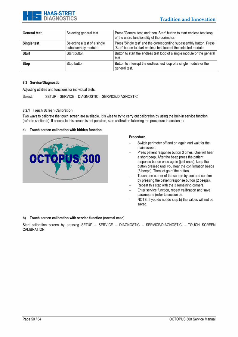
Two ways to calibrate the touch screen are available. It is wise to try to carry out calibration by using the built-in service function (refer to section b). If access to this screen is not possible, start calibration following the procedure in section a). a) Touch screen calibration with hidden function
Procedure
Switch perimeter off and on again and wait for the main screen.
Press patient response button 3 times. One will hear a short beep. After the beep press the patient response button once again (just once), keep the button pressed until you hear the confirmation beeps (3 beeps). Then let go of the button.
Touch one corner of the screen by pen and confirm by pressing the patient response button (2 beeps).
Repeat this step with the 3 remaining corners.
Enter service function, repeat calibration and save parameters (refer to section b).
NOTE: If you do not do step b) the values will not be saved.
b) Touch screen calibration with service function (normal case)
Start calibration screen by pressing SETUP – SERVICE – DIAGNOSTIC – SERVICE/DIAGNOSTIC – TOUCH SCREEN CALIBRATION.
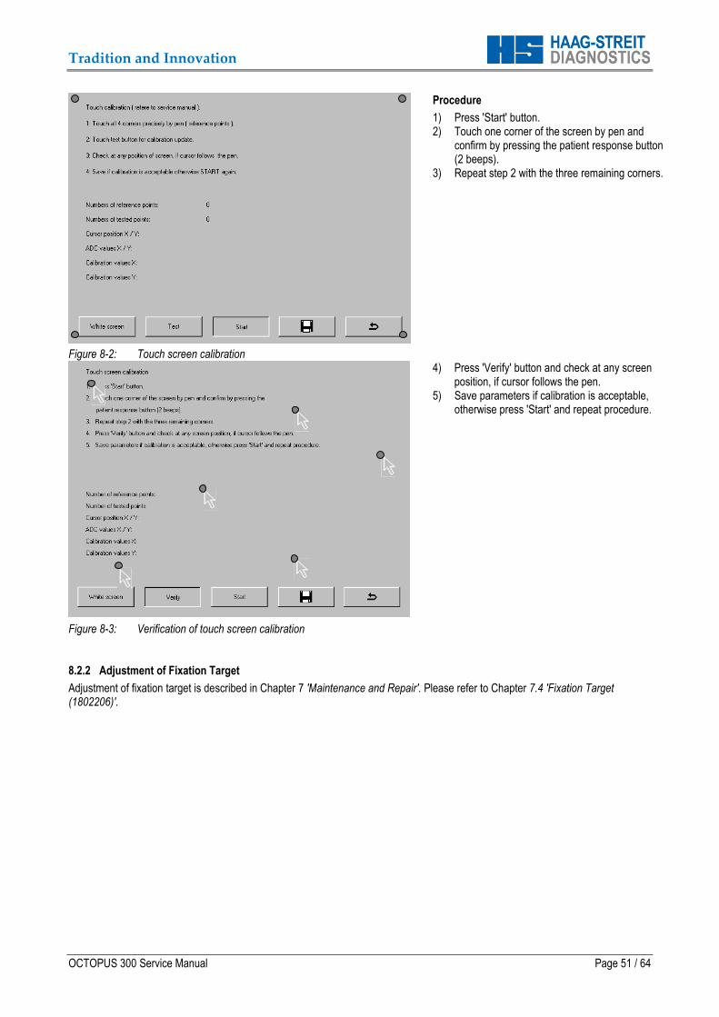
Tradition and Innovation
OCTOPUS 300 Service Manual Page 51 / 64
Figure 8-2: Touch screen calibration
Procedure
1) Press 'Start' button. 2) Touch one corner of the screen by pen and
confirm by pressing the patient response button (2 beeps).
3) Repeat step 2 with the three remaining corners.
Figure 8-3: Verification of touch screen calibration
4) Press 'Verify' button and check at any screen position, if cursor follows the pen.
5) Save parameters if calibration is acceptable, otherwise press 'Start' and repeat procedure.
8.2.2 Adjustment of Fixation Target
Adjustment of fixation target is described in Chapter 7 'Maintenance and Repair'. Please refer to Chapter 7.4 'Fixation Target (1802206)'.
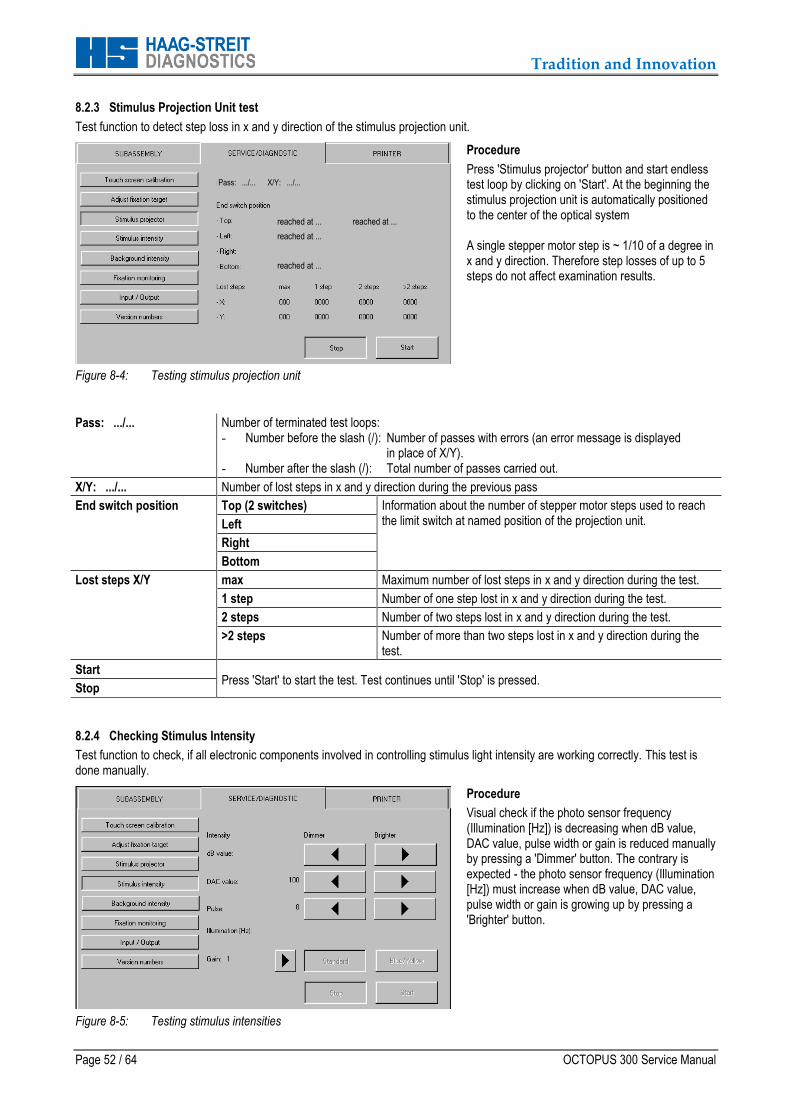
Tradition and Innovation
Page 52 / 64 OCTOPUS 300 Service Manual
8.2.3 Stimulus Projection Unit test
Test function to detect step loss in x and y direction of the stimulus projection unit.
Figure 8-4: Testing stimulus projection unit
Procedure
Press 'Stimulus projector' button and start endless test loop by clicking on 'Start'. At the beginning the stimulus projection unit is automatically positioned to the center of the optical system A single stepper motor step is ~ 1/10 of a degree in x and y direction. Therefore step losses of up to 5 steps do not affect examination results.
Pass: .../... Number of terminated test loops: - Number before the slash (/): Number of passes with errors (an error message is displayed
in place of X/Y). - Number after the slash (/): Total number of passes carried out.
X/Y: .../... Number of lost steps in x and y direction during the previous pass
End switch position Top (2 switches) Information about the number of stepper motor steps used to reach the limit switch at named position of the projection unit. Left
Right
Bottom
Lost steps X/Y max Maximum number of lost steps in x and y direction during the test.
1 step Number of one step lost in x and y direction during the test.
2 steps Number of two steps lost in x and y direction during the test.
>2 steps Number of more than two steps lost in x and y direction during the test.
Start Press 'Start' to start the test. Test continues until 'Stop' is pressed.
Stop
8.2.4 Checking Stimulus Intensity
Test function to check, if all electronic components involved in controlling stimulus light intensity are working correctly. This test is done manually.
Figure 8-5: Testing stimulus intensities
Procedure
Visual check if the photo sensor frequency (Illumination [Hz]) is decreasing when dB value, DAC value, pulse width or gain is reduced manually by pressing a 'Dimmer' button. The contrary is expected - the photo sensor frequency (Illumination [Hz]) must increase when dB value, DAC value, pulse width or gain is growing up by pressing a 'Brighter' button.
reached at ... reached at ...
reached at ...
reached at ...
Pass: .../... X/Y: .../...
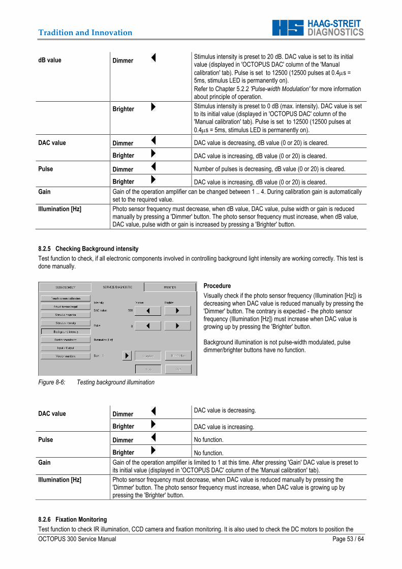
Tradition and Innovation
OCTOPUS 300 Service Manual Page 53 / 64
dB value Dimmer Stimulus intensity is preset to 20 dB. DAC value is set to its initial value (displayed in 'OCTOPUS DAC' column of the 'Manual
calibration' tab). Pulse is set to 12500 (12500 pulses at 0.4s = 5ms, stimulus LED is permanently on).
Refer to Chapter 5.2.2 'Pulse-width Modulation' for more information about principle of operation.
Brighter Stimulus intensity is preset to 0 dB (max. intensity). DAC value is set to its initial value (displayed in 'OCTOPUS DAC' column of the 'Manual calibration' tab). Pulse is set to 12500 (12500 pulses at
0.4s = 5ms, stimulus LED is permanently on).
DAC value Dimmer DAC value is decreasing, dB value (0 or 20) is cleared.
Brighter DAC value is increasing, dB value (0 or 20) is cleared.
Pulse Dimmer Number of pulses is decreasing, dB value (0 or 20) is cleared.
Brighter DAC value is increasing, dB value (0 or 20) is cleared.
Gain Gain of the operation amplifier can be changed between 1 .. 4. During calibration gain is automatically set to the required value.
Illumination [Hz] Photo sensor frequency must decrease, when dB value, DAC value, pulse width or gain is reduced manually by pressing a 'Dimmer' button. The photo sensor frequency must increase, when dB value, DAC value, pulse width or gain is increased by pressing a 'Brighter' button.
8.2.5 Checking Background intensity
Test function to check, if all electronic components involved in controlling background light intensity are working correctly. This test is done manually.
Figure 8-6: Testing background illumination
Procedure
Visually check if the photo sensor frequency (Illumination [Hz]) is decreasing when DAC value is reduced manually by pressing the 'Dimmer' button. The contrary is expected - the photo sensor frequency (Illumination [Hz]) must increase when DAC value is growing up by pressing the 'Brighter' button. Background illumination is not pulse-width modulated, pulse dimmer/brighter buttons have no function.
DAC value Dimmer DAC value is decreasing.
Brighter DAC value is increasing.
Pulse Dimmer No function.
Brighter No function.
Gain Gain of the operation amplifier is limited to 1 at this time. After pressing 'Gain' DAC value is preset to its initial value (displayed in 'OCTOPUS DAC' column of the 'Manual calibration' tab).
Illumination [Hz] Photo sensor frequency must decrease, when DAC value is reduced manually by pressing the 'Dimmer' button. The photo sensor frequency must increase, when DAC value is growing up by pressing the 'Brighter' button.
8.2.6 Fixation Monitoring
Test function to check IR illumination, CCD camera and fixation monitoring. It is also used to check the DC motors to position the
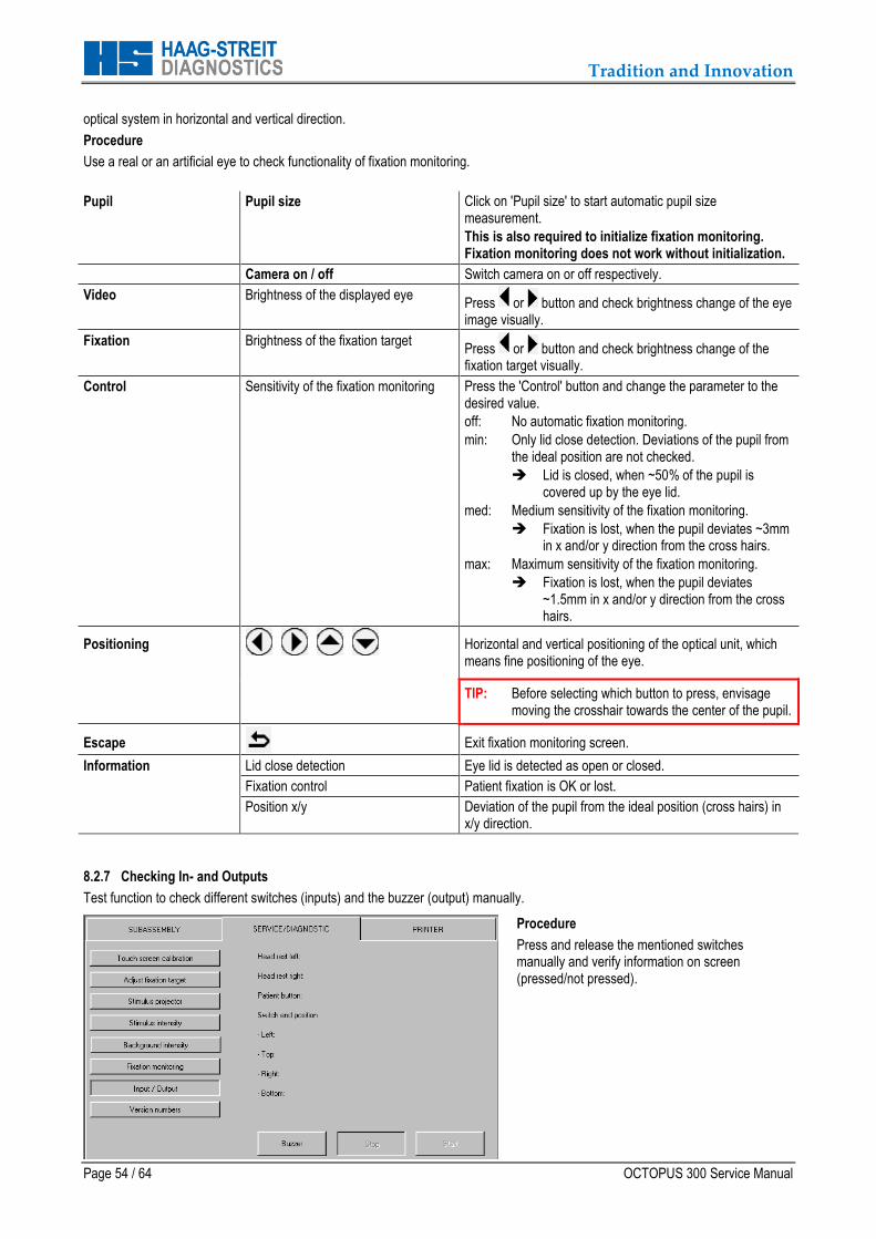
Tradition and Innovation
Page 54 / 64 OCTOPUS 300 Service Manual
optical system in horizontal and vertical direction.
Procedure
Use a real or an artificial eye to check functionality of fixation monitoring.
Pupil Pupil size Click on 'Pupil size' to start automatic pupil size measurement.
This is also required to initialize fixation monitoring. Fixation monitoring does not work without initialization.
Camera on / off Switch camera on or off respectively.
Video Brightness of the displayed eye Press or button and check brightness change of the eye image visually.
Fixation Brightness of the fixation target Press or button and check brightness change of the fixation target visually.
Control Sensitivity of the fixation monitoring Press the 'Control' button and change the parameter to the desired value.
off: No automatic fixation monitoring.
min: Only lid close detection. Deviations of the pupil from the ideal position are not checked.
Lid is closed, when ~50% of the pupil is covered up by the eye lid.
med: Medium sensitivity of the fixation monitoring.
Fixation is lost, when the pupil deviates ~3mm in x and/or y direction from the cross hairs.
max: Maximum sensitivity of the fixation monitoring.
Fixation is lost, when the pupil deviates ~1.5mm in x and/or y direction from the cross hairs.
Positioning
Horizontal and vertical positioning of the optical unit, which means fine positioning of the eye.
TIP: Before selecting which button to press, envisage moving the crosshair towards the center of the pupil.
Escape Exit fixation monitoring screen.
Information Lid close detection Eye lid is detected as open or closed.
Fixation control Patient fixation is OK or lost.
Position x/y Deviation of the pupil from the ideal position (cross hairs) in x/y direction.
8.2.7 Checking In- and Outputs
Test function to check different switches (inputs) and the buzzer (output) manually.
Procedure
Press and release the mentioned switches manually and verify information on screen (pressed/not pressed).
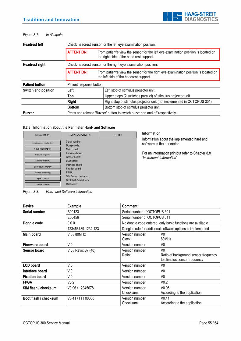
Tradition and Innovation
OCTOPUS 300 Service Manual Page 55 / 64
Figure 8-7: In-/Outputs
Headrest left Check headrest sensor for the left eye examination position.
ATTENTION: From patient's view the sensor for the left eye examination position is located on the right side of the head rest support.
Headrest right Check headrest sensor for the right eye examination position.
ATTENTION: From patient's view the sensor for the right eye examination position is located on the left side of the headrest support.
Patient button Patient response button.
Switch end position Left Left stop of stimulus projector unit.
Top Upper stops (2 switches parallel) of stimulus projector unit.
Right Right stop of stimulus projector unit (not implemented in OCTOPUS 301).
Bottom Bottom stop of stimulus projector unit.
Buzzer Press and release 'Buzzer' button to switch buzzer on and off respectively.
8.2.8 Information about the Perimeter Hard- and Software
Figure 8-8: Hard- and Software information
Information
Information about the implemented hard and software in the perimeter. For an information printout refer to Chapter 8.8 'Instrument Information'.
Device Example Comment
Serial number B00123 Serial number of OCTOPUS 301
E00456 Serial number of OCTOPUS 311
Dongle code 0 0 0 No dongle code entered, only basic functions are available
123456789 1234 123 Dongle code for additional software options is implemented
Main board V 0 / 80MHz Version number: V0 Clock: 80MHz
Firmware board V 0 Version number: V0
Sensor board V 0 / Ratio: 37 (40) Version number: V0 Ratio: Ratio of background sensor frequency
to stimulus sensor frequency
LCD board V 0 Version number: V0
Interface board V 0 Version number: V0
Fixation board V 0 Version number: V0
FPGA V0.2 Version number: V0.2
SIM flash / checksum V0.96 / 12345678 Version number: V0.96 Checksum: According to the application
Boot flash / checksum V0.41 / FFF00000 Version number: V0.41 Checksum: According to the application
Serial number:
Dongle code:
Main board:
Firmware board:
Sensor board:
LCD board:
Interface board:
Fixation board:
FPGA:
SIM flash / checksum:
Boot flash / checksum:
Calibration:

Tradition and Innovation
Page 56 / 64 OCTOPUS 300 Service Manual
Calibration 1.1 / 2.1 / 950.13 / 0000 Stimulus LEDs: 1 LED / 1 calibrated Background modules: 2 rows / 1 calibrated Parameter blocks: Space for 950 / used 13 Checksum: According to the application
8.3 Printer
Not yet implemented. 8.4 Dongle Codes
The Dongle Code function is described in Chapter 4 'Software'. Please refer to 4.2 'Releasing Program Options'. 8.5 Light Intensity Calibration
Select: SETUP – SERVICE – CALIBRATION
NOTE: For safety reasons 'CALIBRATION' will only be released when the two sensors on the forehead support and the 'CALIBRATION' button are pressed simultaneously. As from Serial No. 1030 the head rest sensors have been replaced with non-contact head sensors. In this case hold your hand (close) in front of the head rest and simultaneously press the ‘CALIBRATION‘ button.
8.5.1 Automatic Light Intensity Calibration
Automatic stimulus and background light intensity calibration is a future option and will be added later on. 8.5.2 Manual Light Intensity Calibration
Calibration parameters are individual for all the different instruments. They are determined and stored in the instruments at the end of fabrication process. It is not planned to recalibrate the instruments manually in the field. 8.6 Entering Parameters
IMPORTANT: After replacing the ‘Processor board’ and/ or the ‘Brightness regulator module’, important parameters have to be reentered into the system's memory or modified respectively. Please refer to the corresponding Chapter.
Processor board: See Chapter 7.13.1
Brightness regulator module: See Chapter 7.7.1 'Brightness Regulator Module (1802248)'
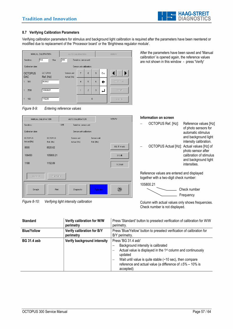
Tradition and Innovation
OCTOPUS 300 Service Manual Page 57 / 64
8.7 Verifying Calibration Parameters
Verifying calibration parameters for stimulus and background light calibration is required after the parameters have been reentered or modified due to replacement of the ‘Processor board’ or the ‘Brightness regulator module’.
Figure 8-9: Entering reference values
After the parameters have been saved and 'Manual calibration' is opened again, the reference values are not shown in this window - press 'Verify'
Figure 8-10: Verifying light intensity calibration
Information on screen
OCTOPUS Ref. [Hz]: Reference values [Hz] of photo sensors for automatic stimulus and background light intensity calibration.
OCTOPUS Actual [Hz]: Actual values [Hz] of photo sensor after calibration of stimulus and background light intensities.
Reference values are entered and displayed together with a two-digit check number:
105800.21 Column with actual values only shows frequencies. Check number is not displayed.
Standard Verify calibration for W/W perimetry
Press 'Standard' button to preselect verification of calibration for W/W perimetry.
Blue/Yellow Verify calibration for B/Y perimetry
Press 'Blue/Yellow' button to preselect verification of calibration for B/Y perimetry.
BG 31.4 asb Verify background intensity Press 'BG 31.4 asb'
Background intensity is calibrated
Actual value is displayed in the 1st column and continuously updated
Wait until value is quite stable (~10 sec), then compare
reference and actual value (a difference of 5% – 10% is accepted)
8500 8520.62
106450 105800.21
1188 1152.89
OCTOPUS
DAC Ref. [Hz]
Check number
Frequency

Tradition and Innovation
Page 58 / 64 OCTOPUS 300 Service Manual
S 0 dB Verify 0dB (max.) stimulus (operating point 1)
Press S 0 dB'
Maximum stimulus intensity is calibrated
Actual value is displayed in the 1st column and continuously updated
Wait until value is quite stable (~10 sec), then compare
reference and actual value (a difference of 5% – 10% is accepted)
S 20 dB Verify 20dB stimulus (operating point 2)
Press S 20 dB'
20 dB stimulus intensity is calibrated
Actual value is displayed in the 1st column and continuously updated
Wait until value is quite stable (~10 sec), then compare
reference and actual value (a difference of 5% – 10% is accepted)
8.8 Instrument Information
Figure 8-11: Setup – Service – Print
Instrument information
The complete instrument information can be printed out via 'Setup' – 'Service' – 'Print'.
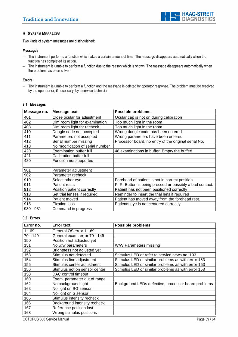
Tradition and Innovation
OCTOPUS 300 Service Manual Page 59 / 64
9 SYSTEM MESSAGES
Two kinds of system messages are distinguished:
Messages
The instrument performs a function which takes a certain amount of time. The message disappears automatically when the function has completed its action.
The instrument is unable to perform a function due to the reason which is shown. The message disappears automatically when the problem has been solved.
Errors
The instrument is unable to perform a function and the message is deleted by operator response. The problem must be resolved by the operator or, if necessary, by a service technician.
9.1 Messages
Message no. Message text Possible problems
401 Close ocular for adjustment Ocular cap is not on during calibration
402 Dim room light for examination Too much light in the room
403 Dim room light for recheck Too much light in the room
410 Dongle code not accepted Wrong dongle code has been entered
411 Parameters not accepted Wrong parameters have been entered
412 Serial number missing Processor board, no entry of the original serial No.
413 No modification of serial number
420 Examination buffer full 48 examinations in buffer. Empty the buffer!
421 Calibration buffer full
430 Function not supported
901 Parameter adjustment
902 Parameter recheck
910 Select other eye Forehead of patient is not in correct position.
911 Patient rests P. R. Button is being pressed or possibly a bad contact.
912 Position patient correctly Patient has not been positioned correctly
913 Set trial lenses if required Reminder to insert the trial lens if required
914 Patient moved Patient has moved away from the forehead rest.
915 Fixation loss Patients eye is not centered correctly
930 - 931 Command in progress
9.2 Errors
Error no. Error text Possible problems
1 - 69 General OS error 1 - 69
70 - 149 General exam. error 70 - 149
150 Position not adjusted yet
151 No w/w parameters W/W Parameters missing
152 Brightness not adjusted yet
153 Stimulus not detected Stimulus LED or refer to service news no. 103
154 Stimulus fine adjustment Stimulus LED or similar problems as with error 153
155 Stimulus center adjustment Stimulus LED or similar problems as with error 153
156 Stimulus not on sensor center Stimulus LED or similar problems as with error 153
158 DAC control timeout
160 Exam. parameter out of range
162 No background light Background LEDs defective, processor board problems
163 No light on BG sensor
164 No light on S sensor
165 Stimulus intensity recheck
166 Background intensity recheck
167 Reference position lost
168 Wrong stimulus positions

Tradition and Innovation
Page 60 / 64 OCTOPUS 300 Service Manual
Error no. Error text Possible problems
170 No b/y parameters B/Y Parameters missing
171 Stimulus intensity too low Stimulus LED defective, Processor board problems
172 Background intensity too low Background LEDs defective, processor board problems
173 0dB stimulus adjustment range
174 20dB stimulus adjustment range
175 Background adjustment range
176 0dB stimulus out of tolerance
177 20dB stimulus out of tolerance
178 Background out of tolerance
179 0dB stimulus adjustment timeout
180 Too bright for light adjustment
181 Too bright for position recheck
182 Stimulus projector timeout
183 Limit switch(es) not reached Broken switch, see service news no. 103
184 Limit switch(es) pressed Broken switch, see service news no. 103
185 Limit switch(es) detected Broken switch, see service news no. 103
186 Upper limit switch not reached Broken switch, see service news no. 103
187 Bottom limit switch not reached Broken switch, see service news no. 103
188 Left limit switch not reached Broken switch, see service news no. 103
189 Right limit switch not reached Broken switch, see service news no. 103
190 Upper limit switch pressed Broken switch, see service news no. 103
191 Bottom limit switch pressed Broken switch, see service news no. 103
192 Left limit switch pressed Broken switch, see service news no. 103
193 Right limit switch pressed Broken switch, see service news no. 103
194 Upper limit switch detected Broken switch, see service news no. 103
195 Bottom limit switch detected Broken switch, see service news no. 103
196 Left limit switch detected Broken switch, see service news no. 103
197 Right limit switch detected Broken switch, see service news no. 103
198 20dB stim. adjustment timeout Stimulus LED, Stimulus Projector, Processor p.c.b.
199 Background adjustment timeout Background LEDs, Processor p.c.b.
200 No response from PC Communication problems: PC settings, software setting
201 PC not ready See description for error No. 200
202 Transmission error See description for error No. 200
203 Receiver error See description for error No. 200
231 Battery low Battery defective, processor board
232 USB power failed
233 SIM flash checksum
234 Boot flash checksum
235 Calibration flash checksum
236 Memory error
237 Video RAM error
238 Battery buffer
239 Setup parameters lost After a reset reenter the setup parameters
240 Examinations lost
241 Sensor board connection Check board connection
242 Interface board connection Check board connection
243 Fixation board connection Check board connection
244 Limit switch connection Check switch connection
245 Battery buffer cleared Battery, processor p.c.b.
251 Stimulus size relation Position of stimulus projector, see service news no. 103
252 Stimulus DAC error Procesor p.c.b.
253 Background DAC error Procesor p.c.b.
256 Steps lost in x direction Stimulus projector
257 Steps lost in y direction Stimulus projector
258 Steps lost in x and y direction Stimulus projector
261 Data reception failed
262 Data reception incomplete
263 Wrong character
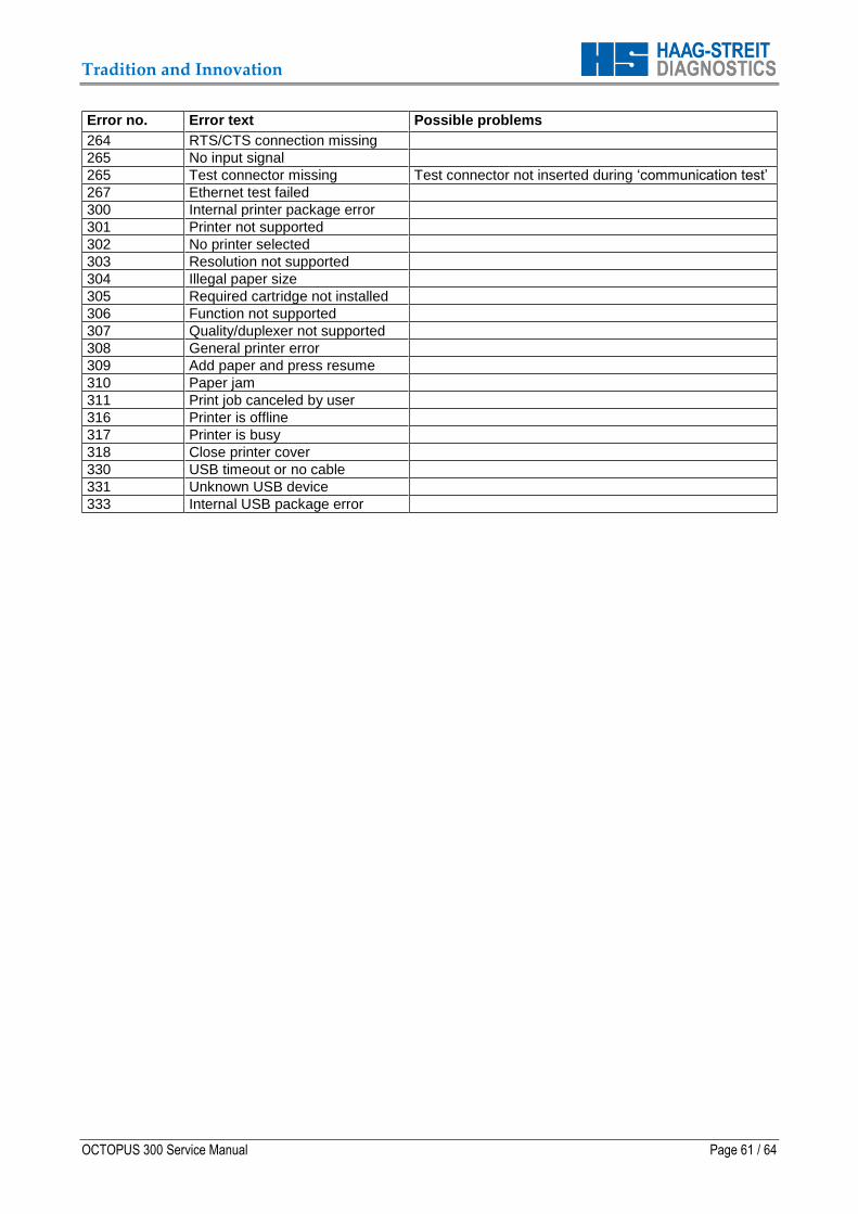
Tradition and Innovation
OCTOPUS 300 Service Manual Page 61 / 64
Error no. Error text Possible problems
264 RTS/CTS connection missing
265 No input signal
265 Test connector missing Test connector not inserted during ‘communication test’
267 Ethernet test failed
300 Internal printer package error
301 Printer not supported
302 No printer selected
303 Resolution not supported
304 Illegal paper size
305 Required cartridge not installed
306 Function not supported
307 Quality/duplexer not supported
308 General printer error
309 Add paper and press resume
310 Paper jam
311 Print job canceled by user
316 Printer is offline
317 Printer is busy
318 Close printer cover
330 USB timeout or no cable
331 Unknown USB device
333 Internal USB package error

Tradition and Innovation
Page 62 / 64 OCTOPUS 300 Service Manual
10 APPENDIX
10.1 Technical Data
Manufacturer
HAAG-STREIT AG Gartenstadtstrasse 10 CH-3098 Köniz/Bern Switzerland
Instrument
Designation: OCTOPUS 301 OCTOPUS 300/ OCTOPUS 311
Power requirements: 100 - 240 V AC, 50 / 60 Hz 100 - 240 V AC, 50 / 60 Hz
Power consumption: 40 VA 40 VA
Fuses: 2 x T3.15 A H 250 V 2 x T3.15 A H 250 V
Classification: Class I, Type B applied parts Class I, Type B applied parts
Measurements (W x L x H): 450 x 530 x 560 mm 450 x 530 x 560 mm
Footprint: 0.20 m2 (450 x 450 mm) 0.20 m2 (450 x 450 mm)
Weight: 22 kg 22 kg
Shipping size: 500 x 580 x 660 mm 500 x 580 x 660 mm
Shipping weight: 35 kg 35 kg
Temperature: Operation: +15°C ... +40°C Operation: +15°C ... +40°C
Storage, transport: -20°C ... +60°C Storage, transport: -20°C ... +60°C
Humidity: Operation: 20% ... 75% Operation: 20% ... 75%
Storage, transport: 10% ... 95% Storage, transport: 10% ... 95%
Operation principle: Direct projection perimeter Direct projection perimeter
Measurement principle: Bracketing procedure Bracketing procedure
Patient positioning: Adjustable headrest Adjustable headrest
Fixation monitoring: Permanent video monitoring Permanent video monitoring
Eccentricity: 30° 30°
Measurement range: 0 ... 40 dB 0 ... 40 dB
Measurement accuracy: 1dB 1dB
Max. stimulus intensity: 1592 cd/m2 (5000 asb) 1592 cd/m2 (5000 asb)
Stimulus color (I): yellow (590 nm) yellow (590 nm)
Stimulus color (II): ------- blue (480 nm)
Stimulus size: Goldmann III, V Goldmann III, V
Stimulus duration: 100 ms, 200 ms 100 ms, 200 ms
Stimulus interval: adaptive, fixed 1.5 ... 4 sec adaptive, fixed 1.5 ... 4 sec
Background intensity (I): 10 cd/m2 (31.4 asb) 10 cd/m2 (31.4 asb)
Background color (I): white (LED) white (LED)
Background intensity (II): ------- 100 cd/m2, (314 asb)
Background color (II): ------- yellow (530 nm)
Interfaces: RS232, USB (Printer) RS232, Ethernet, USB (Printer)
Display device: Color LCD (640 x 480 pixels) Color LCD (640 x 480 pixels)
Data input: Resistive touch module Resistive touch module
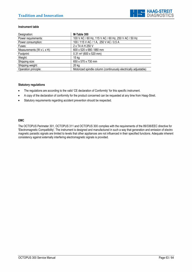
Tradition and Innovation
OCTOPUS 300 Service Manual Page 63 / 64
Instrument table
Designation: M-Table 300
Power requirements: 100 V AC / 60 Hz, 115 V AC / 60 Hz, 250 V AC / 50 Hz
Power consumption: 100 / 115 V AC / 1 A, 250 V AC / 0.5 A
Fuses: 2 x T4 A H 250 V
Measurements (W x L x H): 600 x 520 x 680 / 880 mm
Footprint: 0.31 m2 (600 x 520 mm)
Weight: 15 kg
Shipping size: 650 x 570 x 730 mm
Shipping weight: 20 kg
Operation principle: Motorized spindle column (continuously electrically adjustable)
Statutory regulations
The regulations are according to the valid ‘CE declaration of Conformity’ for this specific instrument.
A copy of the declaration of conformity for the product concerned can be requested at any time from Haag-Streit.
Statutory requirements regarding accident prevention should be respected.
EMC
The OCTOPUS Perimeter 301, OCTOPUS 311 and OCTOPUS 300 complies with the requirements of the 89/336/EEC directive for 'Electromagnetic Compatibility'. The instrument is designed and manufactured in such a way that generation and emission of electro magnetic parasitic signals are limited to levels that other appliances are not influenced in their specified functions. Adequate inherent consistency against externally interfering electromagnetic signals is provided.

Tradition and Innovation
Page 64 / 64 OCTOPUS 300 Service Manual
Should you have any further questions, please contact your HAAG-STREIT representative at:
Technical specifications are subject to change without notice.