Octane Render User Manual
151
user manual version 1.10 Greek Vases by Florinmocanu
description
Octane Render is the world's first GPU based, un-biased, physically based renderer.What does that mean?It uses the video card in your computer to render photorealistic results fast...really fast.This allows the user to create stunning works in a fraction of the time of traditional CPU based renderers.
Transcript of Octane Render User Manual
user manualversion 1.10
Greek Vases by Florinmocanu
2
Standalone Edition User ManualoctanerenderTM
OctaneRender™ Standalone Edition User Manual
Version 1.10 (5 February 2013)http://render.otoy.com
© OTOY INC. 2013. All rights reserved.
OctaneRender™ and OTOY® and their logos are trademarks of OTOY Inc.
by Jan Kudelasek
3
Standalone Edition User ManualoctanerenderTM
Table of contents
Chapter 1 : Installation and Overview1 Installation Requirements 6
1.1 Hardware Requirements 61.2 Software Requirements 61.3 Drivers 61.4 Internet Access 7
2 Windows Installation 73 Mac OSX Installation 84 GNU Linux Installation 85 Hardware Options 96 Troubleshooting 13
Chapter 2 : Program Overview1 Interface Overview 242 The Render Viewport 253 The Node Inspector 264 The Graph Editor 275 The Outliner 306 Octane Live Account Settings 317 Application and Controls 328 The Device Manager 339 The OBJ Mesh Import 33
10 Customizing the Interface 34
Chapter 3 : Exporting (Preparing Your Scene for OctaneRender™)1 Export Script Overview 36
1.1 Project Configuration 371.2 Export Configuration 381.3 Exporting 38
2 Manual Exporting 412.1 Common Export Settings 42
Chapter 4 : Using OctaneRender™1 Using the Preview Macro 472 Importing 47
2.1 Setting Import Preferences 472.2 Importing the Scene 49
3 Navigating the Scene 504 Render Settings 52
4.1 Direct Lighting 534.2 Path Tracing 584.3 PMC 604.4 Deep Image Channel 63
4
Standalone Edition User ManualoctanerenderTM
5 Adjusting Materials 655.1 Working with Material Data 665.2 Value Types 665.3 Texture Types 67
5.3.1 Colour Textures 685.3.2 Image Textures 685.3.3 Texture Generators 695.3.4 Fall Off Texture Map 76
5.4 Diffuse Materials 795.5 Glossy Materials 805.6 Specular (Glass) Materials 835.7 Material Mix 855.8 Portal Materials 865.9 Medium Nodes 87
6 Adjusting Lighting 946.1 Environment Maps / HDRI Environments 956.2 Sun/Sky Environment (Daylight) 976.3 Mesh Emitters 996.4 Clay Rendering Modes 1036.5 Using Portals 104
7 Adjusting the Camera 1068 Adjusting the Camera Imager 1079 Adjusting the Post-processing Preview 11110 Creating Macro Nodes 11411 The Shadow Catcher 11712 The Live Material Database 118
Chapter 5 : Saving and Loading Scenes in OctaneRender™1 Saving / Loading Scenes 1202 Reloading / Textures / Images / Objects 121
Chapter 6 : Geomtery1 Using Instances 1232 Scatter and Multi-Scattering 1273 The Material Map Node 130
Appendix I : Advanced Topics1 Launching Octane from the Command Line 1322 One-Click Turn-Table Animations 1373 One-Click Sun / Sky Animations 1384 Normal Maps and Bump Maps 139
Appendix II : Camera Response Curve ExamplesCamera Response Curve Examples 141
5
Standalone Edition User ManualoctanerenderTM
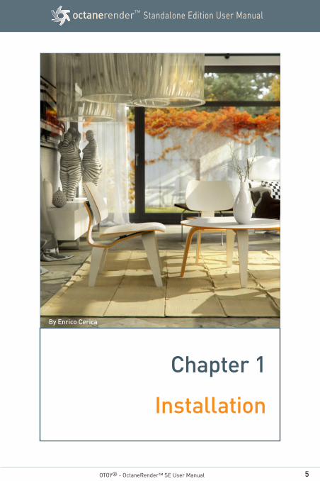
By Enrico Cerica
OTOY® - OctaneRender™ SE User Manual
Chapter 1
Installation
6
Standalone Edition User ManualoctanerenderTM
1. Installation Requirements
1.1 Hardware Requirements
OctaneRender™ requires a NVIDIA CUDA-enabled video card.
OctaneRender™ runs best on Fermi (e.g. GTX 480, GTX 580, GTX 590) and Kepler (e.g. GTX 680, GTX 690) GPUs, but also supports older CUDA enabled GPU models. GeForce cards are fast and cost effec-tive, but have less VRAM than Quadro and Tesla cards. OctaneRender scales perfectly in a multi GPU configuration and can use different types of Nvidia cards at once e.g. a GeForce GTX 260 combined with a Quadro 6000. The official list of NVIDIA CUDA enabled products is located at https://developer.nvidia.com/cuda-gpus.
1.2 Software Requirements
OctaneRender™ is available for the following operating systems : • Windows XP, Windows Vista, Windows 7, Windows 8 (32 and 64 bit) • Linux (64 bit only)
• Macintosh OSX (32 and 64 bit)
1.3 Drivers
OctaneRender requires a Nvidia driver supporting CUDA 4.2. On Windows and Linux you only need a recent enough Nvidia driver (http://www.nvidia.com/download/index.aspx?). For MacOS we recommend using driver version 4.2.10 (http://www.nvidia.com/object/mac-driv-er-archive.html).
OTOY® - OctaneRender™ SE User Manual - Chapter 1 - Section 1
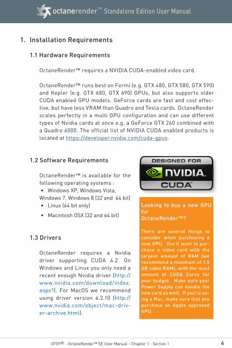
Looking to buy a new GPU for OctaneRender™?
There are several things to consider when purchasing a new GPU. You'll want to pur-chase a video card with the largest amount of RAM (we recommend a minimum of 1.5 GB video RAM), with the most amount of CUDA Cores for your budget. Make sure your Power Supply can handle the new card as well. If you're us-ing a Mac, make sure that you purchase an Apple approved GPU.
7
Standalone Edition User ManualoctanerenderTM
OTOY® - OctaneRender™ SE User Manual - Chapter 1 - Section 1
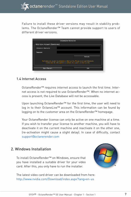
Failure to install these driver versions may result in stability prob-lems. The OctaneRender™ Team cannot provide support to users of different driver versions.
1.4 Internet Access
OctaneRender™ requires internet access to launch the first time. Inter-net access is not required to use OctaneRender™. When no internet ac-cess is present, the Live Database will not be accessable.
Upon launching OctaneRender™ for the first time, the user will need to log in to their OctaneLive™ account. This information can be found by logging on to the customer area on the OctaneRender™ homepage.
Your OctaneRender license can only be active on one machine at a time. If you wish to transfer your license to another machine, you will have to deactivate it on the current machine and reactivate it on the other one, (re-activation might cause a slight delay). In case of difficulty, contact [email protected]
2. Windows Installation
To install OctaneRender™ on Windows, ensure that you have installed a suitable driver for your video card. After this, you only have to run the installer.
The latest video card driver can be downloaded from here: http://www.nvidia.com/Download/index.aspx?lang=en-us
8
Standalone Edition User ManualoctanerenderTM
OTOY® - OctaneRender™ SE User Manual - Chapter 1 - Section 3
3. Mac OSX Installation
To install OctaneRender™ on Mac OSX 10.5 and OSX 10.6 (32 and 64 bit), you will need a recent enough CUDA driver. We recommend using driver version 4.2.10. which can be downloaded from http://www.nvidia.com/object/mac-driver-archive.html.
For users of Mac OSX 10.5 only, the installation of the XQuartz package avail-able from:
http://xquartz.macosforge.org/trac/wiki/X112.6.3
Download the X11-2.5.3.dmg package and install it prior to running Octa-neRender™ the first time. The XQuartz package is not needed for Mac OSX 10.6 users.
4. GNU Linux Installation
To install OctaneRender™ on GNU Linux (64 bit only) you will need a recent enough Nvidia driver which can be down-loaded from:
http://www.nvidia.com/download/index.aspx?
OctaneRender™ for Linux was built and tested on CentOS 5.6 using GCC 4.1.2. Due to that libstdc++ must be of version 4.1.2 or higher.
By Ironelix
9
Standalone Edition User ManualoctanerenderTM
OTOY® - OctaneRender™ SE User Manual - Chapter 1 - Section 5
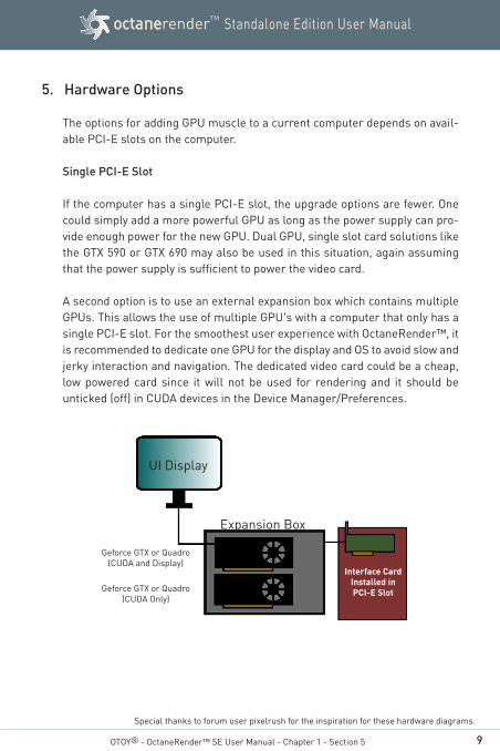
5. Hardware Options
The options for adding GPU muscle to a current computer depends on avail-able PCI-E slots on the computer.
Single PCI-E Slot
If the computer has a single PCI-E slot, the upgrade options are fewer. One could simply add a more powerful GPU as long as the power supply can pro-vide enough power for the new GPU. Dual GPU, single slot card solutions like the GTX 590 or GTX 690 may also be used in this situation, again assuming that the power supply is sufficient to power the video card.
A second option is to use an external expansion box which contains multiple GPUs. This allows the use of multiple GPU's with a computer that only has a single PCI-E slot. For the smoothest user experience with OctaneRender™, it is recommended to dedicate one GPU for the display and OS to avoid slow and jerky interaction and navigation. The dedicated video card could be a cheap, low powered card since it will not be used for rendering and it should be unticked (off) in CUDA devices in the Device Manager/Preferences.
Special thanks to forum user pixelrush for the inspiration for these hardware diagrams.
UI Display
Interface CardInstalled in PCI-E Slot
Expansion Box
Geforce GTX or Quadro (CUDA and Display)
Geforce GTX or Quadro (CUDA Only)
10
Standalone Edition User ManualoctanerenderTM
OTOY® - OctaneRender™ SE User Manual - Chapter 1 -Section 5
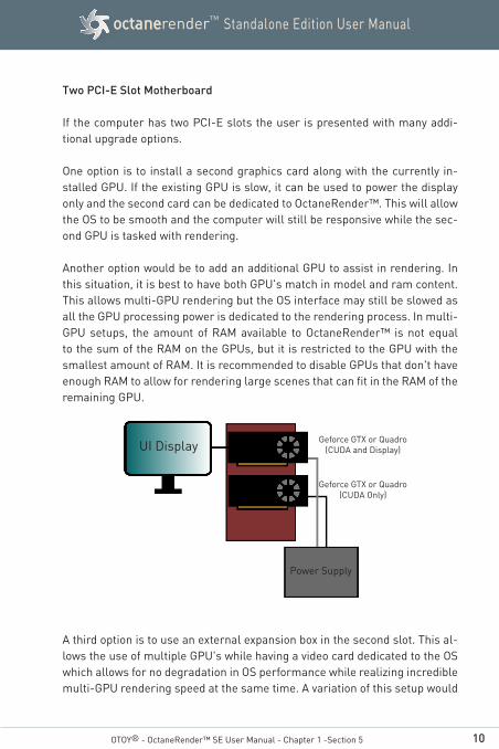
Two PCI-E Slot Motherboard
If the computer has two PCI-E slots the user is presented with many addi-tional upgrade options.
One option is to install a second graphics card along with the currently in-stalled GPU. If the existing GPU is slow, it can be used to power the display only and the second card can be dedicated to OctaneRender™. This will allow the OS to be smooth and the computer will still be responsive while the sec-ond GPU is tasked with rendering.
Another option would be to add an additional GPU to assist in rendering. In this situation, it is best to have both GPU's match in model and ram content. This allows multi-GPU rendering but the OS interface may still be slowed as all the GPU processing power is dedicated to the rendering process. In multi-GPU setups, the amount of RAM available to OctaneRender™ is not equal to the sum of the RAM on the GPUs, but it is restricted to the GPU with the smallest amount of RAM. It is recommended to disable GPUs that don't have enough RAM to allow for rendering large scenes that can fit in the RAM of the remaining GPU.
A third option is to use an external expansion box in the second slot. This al-lows the use of multiple GPU's while having a video card dedicated to the OS which allows for no degradation in OS performance while realizing incredible multi-GPU rendering speed at the same time. A variation of this setup would
UI DisplayGeforce GTX or Quadro
(CUDA and Display)
Geforce GTX or Quadro (CUDA Only)
Power Supply
11
Standalone Edition User ManualoctanerenderTM
OTOY® - OctaneRender™ SE User Manual - Chapter 1 - Section 5
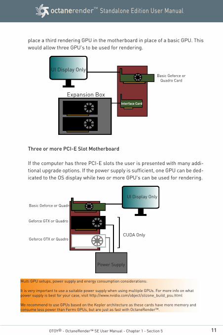
place a third rendering GPU in the motherboard in place of a basic GPU. This would allow three GPU's to be used for rendering.
Three or more PCI-E Slot Motherboard
If the computer has three PCI-E slots the user is presented with many addi-tional upgrade options. If the power supply is sufficient, one GPU can be ded-icated to the OS display while two or more GPU's can be used for rendering.
UI Display OnlyBasic Geforce or
Quadro Card
Interface Card
Expansion Box
Multi GPU setups, power supply and energy consumption considerations:
It is very important to use a suitable power supply when using multiple GPUs. For more info on what power supply is best for your case, visit http://www.nvidia.com/object/slizone_build_psu.html
We recommend to use GPUs based on the Kepler architecture as these cards have more memory and consume less power than Fermi GPUs, but are just as fast with OctaneRender™.
Geforce GTX or Quadro
Geforce GTX or Quadro
Basic Geforce or Quadro
Power Supply
UI Display Only
CUDA Only
12
Standalone Edition User ManualoctanerenderTM
3Dconnexion Space navigator support
OctaneRender™ supports camera movement with a 3D mouse on all plat-forms. The movement is camera-centric: movements you make will be translated to camera movements.
Setup
Make sure the correct drivers for your 3D mouse are installed. On Windows and Mac OS X your 3D mouse should work after you plug in the 3D mouse. On Linux you should make sure the driver is running before you start OctaneR-ender™. If you start the driver later, lock and unlock the viewport to detect the 3D mouse.
On Windows, the settings from the 3Dconnexion control panel have no effect. You can change the speed of the movements and invert setting in the menu'sPreferences > Controls in OctaneRender.
OTOY® - OctaneRender™ SE User Manual - Chapter 1 - Section 5
13
Standalone Edition User ManualoctanerenderTM
OTOY® - OctaneRender™ SE User Manual - Chapter 1 - Section 6
Special thanks to forum user pixelrush for the compilation of this troubleshooting information.
6. Troubleshooting
Most problems with OctaneRender™ can be traced to the following situations. Please refer to the issue numbers listed to find common solutions.
Issue Description
6.1 Cannot find driver for laptop or computer
6.2 OctaneRender™ won't open due to "No Cuda Devices"
6.3 OctaneRender™ won't open due to License Issues
6.4 OctaneRender™ crashes loading a file
6.5 Render looks strange or gives unexpected results
6.6 Navigation of Viewport is slow / UI is Unresponsive
6.7 ctaneRender™ works for a while then closes while rendering
6.8 Can't change settings or save renders
6.9 OctaneRender™ does not see all available video cards
6.10 Additional Helpful Hints
14
Standalone Edition User ManualoctanerenderTM
OTOY® - OctaneRender™ SE User Manual - Chapter 1 - Section 6
6.1 Cannot Find Drivers for Laptop or Computer
Problem: The available OEM drivers are not recent enough
Solution: As a work around, find a suitable official Nvidia driver, unzip the executable, and modify the device list to include your hardware. Then, manually install the driver. See forum or search internet for more detailed information.
Problem: Newly released card and waiting for updated Nvidia driver to support it
Solution: The new drivers should be released shortly. OctaneR-ender™ and Cuda are in constant development and new hardware and Cuda revisions are being released regularly. There are a few occasions where this situation occurs and causes a delay in getting the most out of your hardware and OctaneRender™.
6.2 OctaneRender™ Won't Open Due to "No Cuda Devices" Error Message
Problem: Incorrect Driver installed
Solution: Read the release notes to ensure that you have the cor-rect driver version installed.
Attempt to remove the old driver versions and then install the proper version. It may be necessary to use a tool such as Driver Sweeper to get all driver components uninstalled.
15
Standalone Edition User ManualoctanerenderTM
OTOY® - OctaneRender™ SE User Manual - Chapter 1 - Section 6
Problem: Video Card is not Cuda enabled
Solution: Check the list below to ensure that your card is in fact Cuda enabled.
http://developer.nvidia.com/cuda-gpu
It is recommended to use a card with at least 128 Cuda cores and preferably a Fermi generation card with more than 300 Cuda cores or above for decent render perfor-mance. For Kepler cards, a minimum of 768 Cuda cores is recommended.
6.3 OctaneRender™ won't open due to License Issues
Problem: OctaneRender™ is not Licensed
Solution: Your customer details have been incorrectly entered into the licensing system. If you suspect a problem, contact us at [email protected]
Problem: OctaneRender™ is not "Activated"
Solution: Either your license has not been processed or the current license is activated on another machine. Deactivate the copy of OctaneRender™ on the previous machine and activate the new machine after waiting 30 minutes. This can also be accomplished via the customer login area at http://render.otoy.com

16
Standalone Edition User ManualoctanerenderTM
OTOY® - OctaneRender™ SE User Manual - Chapter 1 - Section 6
Problem: OctaneRender™ cannot connect to the OctaneLive™ servers
Solution: This could be due to two issues
1) Configure your firewall or router to allow outbound connections to the URL named live1.octanerender.com
2) Your customer details have been incorrectly entered by either you or members of the OctaneRender™ Team into the licensing system. If you suspect a problem, contact us at [email protected]
6.4 OctaneRender™ Crashes Loading a File
If OctaneRender™ crashes upon loading a user created file, ensure that OctaneRender™ and the drivers are installed correctly by downloading and loading the demo suite files located at:
http://render.otoy.com/downloads/OctaneRender_1_0_DemoSuite.zip
Problem: Problems inside Obj file such as stray edges, vertices, etc.
Solution: Re-export the scene using different exporting options from the modeling program or export script
Problem: Special Characters inside Obj or MTL file.
Solution: OctaneRender recognises filenames containing spaces, and it should be able to use files with non-latin charac-ters. An OBJ or MTL file containing special characters may be encoded in UTF-8.
17
Standalone Edition User ManualoctanerenderTM
OTOY® - OctaneRender™ SE User Manual - Chapter 1 - Section 6
Problem: Incompatibility of previous version macros and OCS file format.
Solution: Unfortunately, the only way to get around this is to recre-ate the macros or OCS file in the current version.
Problem: Insufficient system or video ram
Solution: It is recommended to use a 64 bit operating system with more than 4 GB of system ram. Also, if possible use a video card with more than 1 GB of vram.
For example, 1 GB vram is sufficient for 3 million poly-gons with medium texture use and a medium render size. To render in larger resolutions or to utilize more high resolution textures, a video card with more than 1 GB vram might be necessary.
Problem: Display Video Card is not active while CUDA enabled card is active
Solution: This may require swapping video card slots on the moth-erboard or changing bios settings so PCI-E slot with the display is "Initialized First". Review your motherboard documentation for the exact wording and location for this setting.
18
Standalone Edition User ManualoctanerenderTM
OTOY® - OctaneRender™ SE User Manual - Chapter 1 - Section 6
6.5 Render Looks Strange or Gives Unexpected Results
Problem: Concentric circles over the image or unusual effects including bump map not working
Solution: Check the scale of the imported scene and change the rayepsilon value. Typically this is due to the scale being incorrect by a factor of 100 or 1000X. Octane expects 1 unit in the scene to equal 1 meter. Adjust export settings in the modeling application or adjust the import settings in OctaneRender™.
Problem: Facetting occurs revealing the underlying polygonal mesh, Geometry or Normals issues
Solution: Ensure that the geometry and normals are correct in the modeling program. Re-export the scene if neces-sary. Make sure the Normal Smoothing boolean value ("smooth") is enabled for each material in the Node Inspector.
Problem: Bump map does not show up
Solution: When a bump map and normal map are both loaded, the normal map will take priority and the bump map will not be used.
Problem: Images do not look right on the model.
Solution: This may be due to the way the model was UV unwrapped. This may need to be redone more precisely in the 3d modeling application and re-exported.

19
Standalone Edition User ManualoctanerenderTM
OTOY® - OctaneRender™ SE User Manual - Chapter 1 - Section 6
6.6 Navigation of Viewport is Slow / UI is Unresponsive
Problem: Known issue with display refresh time out on Windows
Solution: This can be attributed to a function that is included in some operating systems that shut down any program after the OS has lost communication with the GPU. Since higher resolutions and Path Tracing both can take long periods of time to render a single frame, the OS loses contact with the GPU and shuts down Octane
This can be resolved one of two ways.
1. Purchase a second GPU and dedicate one to OctaneR-ender™ and one to the operating system
2. Adjust the time out values specific to the operating system.
As this typically involves adjusting critical OS files, it is not recommended and not supported by the OctaneRen-der™ Team.
For Microsoft Windows systems, more information can be read here:
http://www.microsoft.com/whdc/device/display/wddm_timeout.mspx
Problem: Render card has insufficient performance
Solution: 96 Cuda cores are considered the absolute minimum although OctaneRender™ will technically work with fewer. It is suggested that a more powerful GPU (Fermi or Kepler recommended) be purchased to get the most out of OctaneRender™.

20
Standalone Edition User ManualoctanerenderTM
OTOY® - OctaneRender™ SE User Manual - Chapter 1 - Section 6
Problem: Navigating is slow. Is there anything else I can do?
Solution: To increase the speed of navigating in OctaneRender™, you can: - use the Shift key while rotating, moving or translating
the Render Viewport - use the Sub-Sampling settings (3 checkerboard icons
in the viewport) to increase the speed of navigating in the viewport
- reduce the render resolution of the viewport while set-ting up materials, lights and camera
Problem: Insufficient Power Supply
Solution: The current generation of Cuda enabled GPU's can be very demanding on a computers power supply. When going with multiple video cards it can be even more demanding. Purchase a new power supply if necessary to ensure that all components have sufficient energy to do their task.
Problem: Graphics Card or Computer Overheating
Solution: Make sure the computer case has good ventilation which may include purchasing additional cooling fans or a different case altogether. Ensure the case has a good amount of space around all air intakes and vents. Heat sinks and fans will also build up dust and lose their cool-ing capacity. Use canned air to clean out computer cases, heat sinks and fans regularly.
Free software tools such as Speedfan, EVGA Precision and GPUZ can assist in determining temperatures of the GPU and will assist in setting fan speeds if necessary.
21
Standalone Edition User ManualoctanerenderTM
OTOY® - OctaneRender™ SE User Manual - Chapter 1 - Section 6
6.8 Can't Change Settings or Save Renders in the demo
Problem: Changed settings do not keep when closing and restart-ing Octane
Solution: This is currently not available for Demo Users.
Problem: I cannot save any renders or use the built-in animation tools
Solution: This is currently not available for Demo Users.
6.9 Windows and the Nvidia driver see all available GPU's, but OctaneRen-der™ does not.
There are occasions when using more than two video cards that Windows and the Nvidia driver properly register all cards, but OctaneRender™ does not see them. This can be addressed by updating the registry.
This involves adjusting critical OS files, it is not supported by the Octa-neRender™ Team.
1) Start the registry editor (Start button, type "regedit" and launch it.)
2) Navigate to the following key:
HKEY_LOCAL_MACHINE\SYSTEM\CurrentControlSet\Control\Class\{4D36E968-E325-11CE-BFC1-08002BE10318}
3) You will see keys for each video card starting with "0000" and then "0001", etc.
22
Standalone Edition User ManualoctanerenderTM
OTOY® - OctaneRender™ SE User Manual - Chapter 1 - Section 6
4) Under each of the keys identified in 3 for each video card, add two dword values:
DisplayLessPolicy LimitVideoPresentSources
and set each value to 1
5) Once these have been added to each of the video cards, shut down Regedit and then reboot.
6) OctaneRender™ should now see all video cards
6.10 Additional Helpful Hints
1) PCI-E 16X / 8X / 4X / 2X slots are sufficient to run OctaneRender™. PCI-E 1X slots are not as it slows down the transfer of data too much. PCI-E bandwidth sharing by mixing 16x and 8x slots is possible.
2) It is best to use two or more video cards of the same speed and ram configuration when using them with OctaneRender™
23
Standalone Edition User ManualoctanerenderTM
OTOY® - OctaneRender™ SE User Manual
Chapter 2
Program Overview
By Wojciech Migdal
24
Standalone Edition User ManualoctanerenderTM
OTOY® - OctaneRender™ SE User Manual - Chapter 2 - Section 1
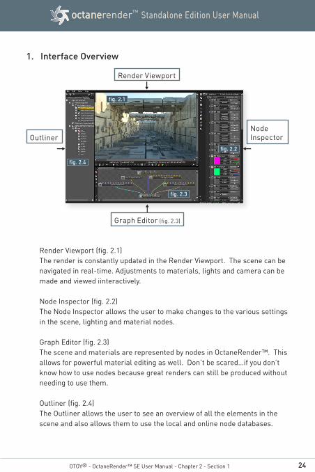
1. Interface Overview
Render Viewport (fig. 2.1)The render is constantly updated in the Render Viewport. The scene can be navigated in real-time. Adjustments to materials, lights and camera can be made and viewed iinteractively.
Node Inspector (fig. 2.2)The Node Inspector allows the user to make changes to the various settings in the scene, lighting and material nodes.
Graph Editor (fig. 2.3)The scene and materials are represented by nodes in OctaneRender™. This allows for powerful material editing as well. Don’t be scared…if you don’t know how to use nodes because great renders can still be produced without needing to use them.
Outliner (fig. 2.4)The Outliner allows the user to see an overview of all the elements in the scene and also allows them to use the local and online node databases.
Render Viewport
Graph Editor (fig. 2.3)
Node Inspector
fig. 2.2
fig. 2.3
Outliner
fig. 2.1
fig. 2.4
25
Standalone Edition User ManualoctanerenderTM
OTOY® - OctaneRender™ SE User Manual - Chapter 2 - Section 2
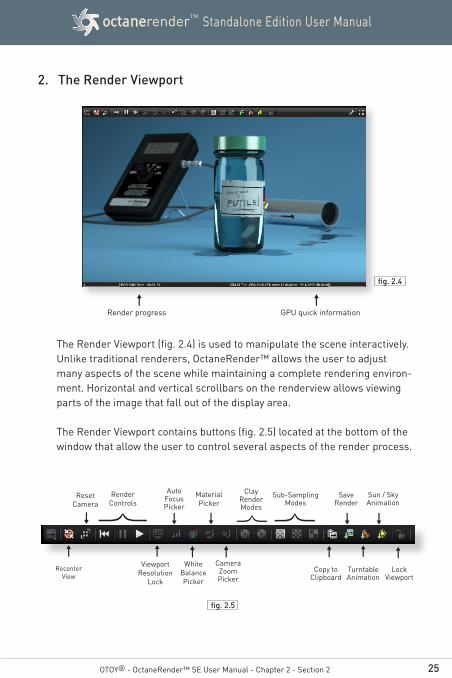
2. The Render Viewport
The Render Viewport (fig. 2.4) is used to manipulate the scene interactively. Unlike traditional renderers, OctaneRender™ allows the user to adjust many aspects of the scene while maintaining a complete rendering environ-ment. Horizontal and vertical scrollbars on the renderview allows viewing parts of the image that fall out of the display area.
The Render Viewport contains buttons (fig. 2.5) located at the bottom of the window that allow the user to control several aspects of the render process.
Render progress GPU quick information
fig. 2.4
fig. 2.5
Render Controls
Reset Camera
Sun / Sky Animation
Auto FocusPicker
Camera Zoom Picker
Sub-SamplingModes Save
Render
Turntable Animation
MaterialPicker
Clay Render Modes
Recenter View
Lock
Viewport
Copy to
Clipboard
Viewport
Resolution Lock
White Balance Picker
26
Standalone Edition User ManualoctanerenderTM
3. The Node Inspector
The Node Inspector (fig. 2.6) is used to make changes to nearly every aspect of the render / scene in OctaneRender™. Any nodes that are selected in the Graph Editor are displayed in the Node Inspector where their values can be adjusted or changed. When using the Material Picker, the currently selected material will also be displayed in the Node Inspector.
The Node Inspector also includes quick buttons (fig. 2.7) that allow the user to quickly jump to the most commonly used nodes (RenderTarget, Camera, Resolution, Environment, Imager, Kernel, Current Mesh). It also has context menus allowing to copy, paste, and fill empty node pins.
The bottom of the Node Inspector window also hosts the status for both the OctaneLive and Online status. (fig. 2.8)
OTOY® - OctaneRender™ SE User Manual - Chapter 2 - Section 3
fig. 2.8
fig. 2.6
fig. 2.7
ExpandAll Nodes
Collapse All Nodes
Preview Render Target
Preview Resolution
Preview Imager
Preview Camera
Preview Environment
Preview Kernel
Preview Mesh
Preview Post-
processing
27
Standalone Edition User ManualoctanerenderTM
4. The Graph Editor
The Graph Editor (fig. 2.9) allows the user to view the nodes associated with the current scene. The Render Target includes all of the scene related nodes including the Environment, Imager, Kernel, Resolution and Camera Nodes. The user can pan the node graph editor with the mouse. Selecting a node in the Graph Editor will bring that node’s settings up in the Node Inspector along with its empty node pins. The user can fill empty node pins either in the Graph Editor or in the Node Inspector. Placing the mouse cur-sor over a node pin will show the name of the material contained in the pin.
Selecting multiple nodes
Start dragging in an empty area of the node graph editor to select multiple nodes with a box. Hold down Shift to add the selection to the current selec-tion. Hold down Ctrl to deselect nodes. You can also add and remove nodes from the selection by holding Ctrl and clicking on a node. The node graph editor supports copy/paste with right clicking or keyboard shortcuts (Ctrl+C and Ctrl+V) and there are application-wide shortcuts for cut, copy, paste and delete commands which are placed in the application menu. Copying and pasting nodes will also duplicate connections coming from other nodes to
OTOY® - OctaneRender™ SE User Manual - Chapter 2 - Section 4
fig. 2.9
28
Standalone Edition User ManualoctanerenderTM
the copied nodes. Dropping of macro and mesh files on the nodegraph edi-tor is also possible.
Right-click on a node for a context menu
Right clicking on a node invokes a context menu with options 'delete' allow-ing you to delete all selected nodes, 'save' saves the selected nodes as a macro file or in LiveDB, and 'render' (if available) which will render the node under the cursor. Node pin connections are saved when saving multiple nodes. The context menu also includes 'Show in Outliner' which will quickly pick and select the respective node's corresponding element in the Outliner.
OTOY® - OctaneRender™ SE User Manual - Chapter 2 - Section 4
fig. 2.10
29
Standalone Edition User ManualoctanerenderTM
Right-click in the node graph editor
By right-clicking in the node graph editor you can import nodes from a file and places the new node on the cursor location.
The Graph Editor also has buttons (fig. 2.12) that allow the display of the internal material preview scene when a node is selected.
Quick material previews
It is possible to enable quick previews of materials and textures inside the node inspector. These will be rendered without interrupting the main ren-der, and will update automatically when the material or texture is changed. The scale of the material can be updated as well.
There is a choice of a preview on a sphere and a flat 2D preview. The scale of the object shown is customizable, and users can choose default settings in the settings dialog.
OTOY® - OctaneRender™ SE User Manual - Chapter 2 - Section 4
fig. 2.11
View/HideRender TargetPreview Scene
View/HideMaterial
Preview Scene
View/HideMesh
Preview Scene
View/HideTexture
Preview Scene
fig. 2.12
Recenter
View
30
Standalone Edition User ManualoctanerenderTM
5. The Outliner
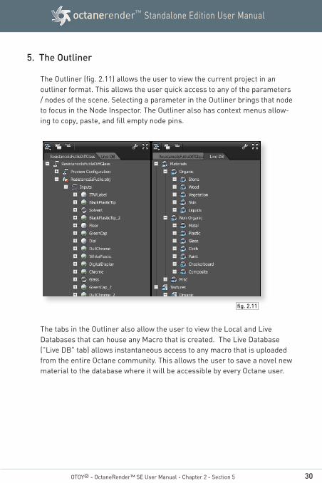
The Outliner (fig. 2.11) allows the user to view the current project in an outliner format. This allows the user quick access to any of the parameters / nodes of the scene. Selecting a parameter in the Outliner brings that node to focus in the Node Inspector. The Outliner also has context menus allow-ing to copy, paste, and fill empty node pins.
The tabs in the Outliner also allow the user to view the Local and Live Databases that can house any Macro that is created. The Live Database ("Live DB" tab) allows instantaneous access to any macro that is uploaded from the entire Octane community. This allows the user to save a novel new material to the database where it will be accessible by every Octane user.
OTOY® - OctaneRender™ SE User Manual - Chapter 2 - Section 5
fig. 2.11
31
Standalone Edition User ManualoctanerenderTM
6. The OctaneLive™ Account Settings
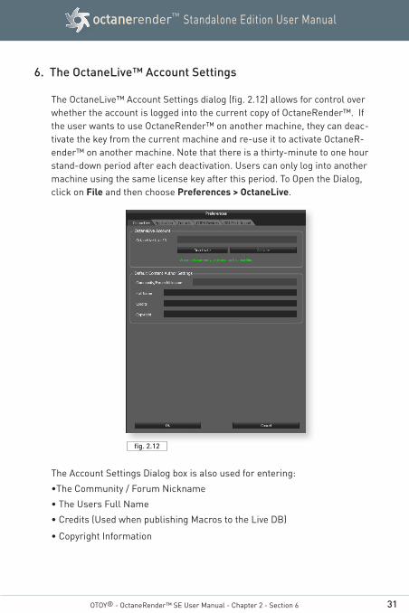
The OctaneLive™ Account Settings dialog (fig. 2.12) allows for control over whether the account is logged into the current copy of OctaneRender™. If the user wants to use OctaneRender™ on another machine, they can deac-tivate the key from the current machine and re-use it to activate OctaneR-ender™ on another machine. Note that there is a thirty-minute to one hour stand-down period after each deactivation. Users can only log into another machine using the same license key after this period. To Open the Dialog, click on File and then choose Preferences > OctaneLive.
The Account Settings Dialog box is also used for entering:
•The Community / Forum Nickname
• The Users Full Name
• Credits (Used when publishing Macros to the Live DB)
• Copyright Information
OTOY® - OctaneRender™ SE User Manual - Chapter 2 - Section 6
fig. 2.12
32
Standalone Edition User ManualoctanerenderTM
7. The Application and Controls Settings
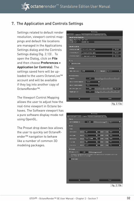
Settings related to default render resolution, viewport control map-pings and default file locations are managed in the Applications Settings dialog and the Controls Settings dialog (fig. 2.13) . To open the Dialog, click on File and then choose Preferences > Application (or Controls). The settings saved here will be up-loaded to the users OctaneLive™ account and will be available if they log into another copy of OctaneRender™.
The Viewport Control Mapping allows the user to adjust how the real-time viewport in Octane be-haves. The Software viewport has a pure software display mode not using OpenGL. The Preset drop down box allows the user to quickly set OctaneR-ender™ navigation to behave like a number of common 3D modeling packages.
OTOY® - OctaneRender™ SE User Manual - Chapter 2 - Section 7
fig. 2.13a
fig. 2.13b
33
Standalone Edition User ManualoctanerenderTM
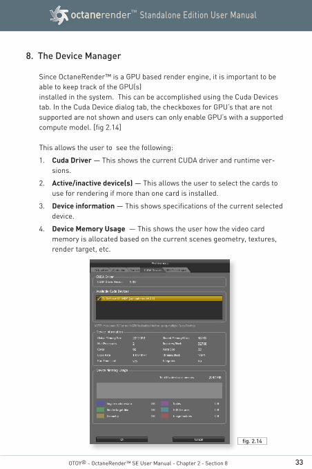
8. The Device Manager
Since OctaneRender™ is a GPU based render engine, it is important to be able to keep track of the GPU(s) installed in the system. This can be accomplished using the Cuda Devices tab. In the Cuda Device dialog tab, the checkboxes for GPU’s that are not supported are not shown and users can only enable GPU’s with a supportedcompute model. [fig 2.14]
This allows the user to see the following:
1. Cuda Driver — This shows the current CUDA driver and runtime ver-sions.
2. Active/inactive device(s) — This allows the user to select the cards to use for rendering if more than one card is installed.
3. Device information — This shows specifications of the current selected device.
4. Device Memory Usage — This shows the user how the video card memory is allocated based on the current scenes geometry, textures, render target, etc.
OTOY® - OctaneRender™ SE User Manual - Chapter 2 - Section 8
fig. 2.14

34
Standalone Edition User ManualoctanerenderTM
9. The OBJ Mesh Import
This allows the user to customize the default settings for importing a mesh modelled from various 3D applications. There is an added option to invert opacity values from MTL files because some 3D applications write them inverted. Note that the reload button only reloads the geometry, users will need to delete the mesh node, change the setting in the OBJ Mesh Import tab and then import again.
10. Customizing the Interface
The toolbars for each area of the OctaneRender™ interface are customiz-able (Graph Editor, Render Viewport, Node Inspector and Outliner.) To customize the toolbar, click on the wrench icon. [fig 2.15]
This will open the Add/Remove Items from Toolbar dialog box. [fig 2.16]
The dialog allows the user to place the toolbar to any edge of the respective area. It also allows the buttons to be re-arranged, added or removed.
OTOY® - OctaneRender™ SE User Manual - Chapter 2 - Section 9
fig. 2.15
fig. 2.16

35
Standalone Edition User ManualoctanerenderTM
Chapter 3
Preparing andExporting Scenes
for Rendering
OTOY® - OctaneRender™ SE User Manual
By Mike Logic
36
Standalone Edition User ManualoctanerenderTM
OTOY® - OctaneRender™ SE User Manual - Chapter 3 - Section 1
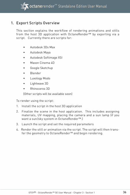
1. Export Scripts Overview
This section explains the workflow of rendering animations and stills from the host 3D application with OctaneRender™ by exporting via a script. Currently there are scripts for:
• Autodesk 3Ds Max
• Autodesk Maya
• Autodesk Softimage XSI
• Maxon Cinema 4D
• Google Sketchup
• Blender
• Luxology Modo
• Lightwave 3D
• Rhinoceros 3D
(Other scripts will be available soon)
To render using the script:
1. Install the script in the host 3D application
2. Finalize the scene in the host application. This includes assigning materials, UV mapping, placing the camera and a sun lamp (if you want a sun/sky system in OctaneRender™.)
3. Launch the script and set the required parameters
4. Render the still or animation via the script. The script will then trans-fer the geometry to OctaneRender™ and begin rendering.

37
Standalone Edition User ManualoctanerenderTM
1.1 Project Configuration
Upon launching the script, the project configuration options must be set. For illustration purposes, the export script for 3dsMax® is shown, but the same parameters discussed here are applicable to other 3D applications.
OctaneRender™ Binary:
Use the browse but-ton to set the location of the OctaneRender™ program
Project Path:
Use the browse but-ton to select a loca-tion where the script should place files re-lated to the export.
Project Name:
If this is the first ex-port, then enter a name in the text box that identifies the scene. If you’d like to use an existing OCS file (to retain the materials and other settings already con-figured in OctaneRen-der™) click on the Use Existing Project button to load the file. The Project Name will then be based on the selected OCS file.
Native Unit Size:(Not shown)
This setting is used to export the geometry at the proper scale. Se-lect the units that best represent 1 unit in the host application. (The resulting object will then be in the proper units since OctaneRen-der™ assumes 1 unit = 1 meter.)
OTOY® - OctaneRender™ SE User Manual - Chapter 3 - Section 1
fig. 3.1 - The Export Script for 3ds Max
38
Standalone Edition User ManualoctanerenderTM
OTOY® - OctaneRender™ SE User Manual - Chapter 3 - Section 1
1.2 Export Configuration
Configuration of export options for film, camera and daylight envi-ronment:
Film
Resolution: Set the resolution of the final render
Camera
Place a checkmark next to any camera / scene element to include in the export and set any required parameter.
Camera / Active Camera: If checked, the selected Active Camera will be used for the export.
Lens Aperture: If checked, the entered Lens Aperture will be used for the export
Focal Depth: If checked, the entered Focal Depth will be used for the export
Camera Motion Blur: If checked, motion blur will be used. The Interpolate setting allows whether to use the next frame or the previous frame to set the two positions to calculate the camera motion blur.
Daylight Environment
Sun Direction: If checked, the position of the light specified in the Light Source box will be used as the position of the Sun in a Sun / Sky environment when exported.
1.3 Export
This section is used to actually start the export and begin rendering the scene in OctaneRender™.
Frame
This area controls exporting only the current single frame and is
39
Standalone Edition User ManualoctanerenderTM
OTOY® - OctaneRender™ SE User Manual - Chapter 3 - Section 1
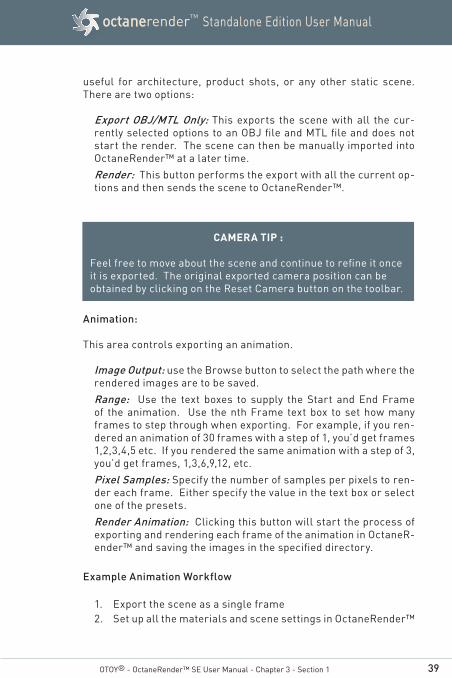
useful for architecture, product shots, or any other static scene. There are two options:
Export OBJ/MTL Only: This exports the scene with all the cur-rently selected options to an OBJ file and MTL file and does not start the render. The scene can then be manually imported into OctaneRender™ at a later time.
Render: This button performs the export with all the current op-tions and then sends the scene to OctaneRender™.
Animation:
This area controls exporting an animation.
Image Output: use the Browse button to select the path where the rendered images are to be saved.
Range: Use the text boxes to supply the Start and End Frame of the animation. Use the nth Frame text box to set how many frames to step through when exporting. For example, if you ren-dered an animation of 30 frames with a step of 1, you’d get frames 1,2,3,4,5 etc. If you rendered the same animation with a step of 3, you’d get frames, 1,3,6,9,12, etc.
Pixel Samples: Specify the number of samples per pixels to ren-der each frame. Either specify the value in the text box or select one of the presets.
Render Animation: Clicking this button will start the process of exporting and rendering each frame of the animation in OctaneR-ender™ and saving the images in the specified directory.
Example Animation Workflow
1. Export the scene as a single frame2. Set up all the materials and scene settings in OctaneRender™
CAMERA TIP :
Feel free to move about the scene and continue to refine it once it is exported. The original exported camera position can be obtained by clicking on the Reset Camera button on the toolbar.
40
Standalone Edition User ManualoctanerenderTM
OTOY® - OctaneRender™ SE User Manual - Chapter 3 - Section 1.3
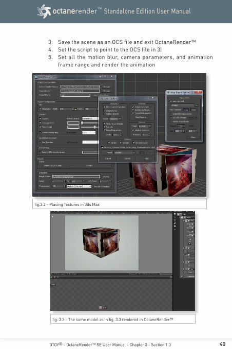
3. Save the scene as an OCS file and exit OctaneRender™4. Set the script to point to the OCS file in 3)5. Set all the motion blur, camera parameters, and animation
frame range and render the animation
fig.3.2 - Placing Textures in 3ds Max
fig. 3.3 - The same model as in fig. 3.3 rendered in OctaneRender™
41
Standalone Edition User ManualoctanerenderTM
2. Manual Exporting
To export a scene for use in OctaneRender™, use your favorite 3D Mode-ling Software's Wavefront Object (obj) export function. The settings avail-able are different for various software packages. The following are some general settings to export if available:
• Materials• Normals• Texture Coordinates• Objects
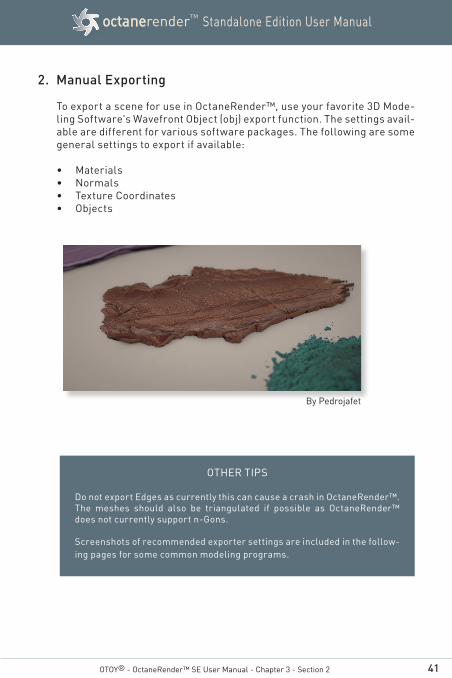
OTOY® - OctaneRender™ SE User Manual - Chapter 3 - Section 2
By Pedrojafet
OTHER TIPS
Do not export Edges as currently this can cause a crash in OctaneRender™. The meshes should also be triangulated if possible as OctaneRender™ does not currently support n-Gons.
Screenshots of recommended exporter settings are included in the follow-ing pages for some common modeling programs.

42
Standalone Edition User ManualoctanerenderTM
2.1 Common Export Settings
Autodesk Maya:
Autodesk 3ds Max:
OTOY® - OctaneRender™ SE User Manual - Chapter 3 - Section 2
fig. 3.4 - Autodesk Maya Export Settings
fig. 3.5 - Autodesk 3ds Max Export Settings
43
Standalone Edition User ManualoctanerenderTM
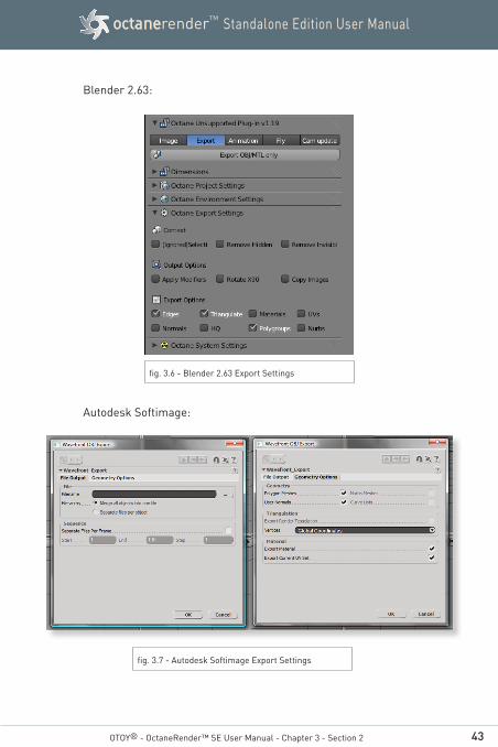
Blender 2.63:
Autodesk Softimage:
OTOY® - OctaneRender™ SE User Manual - Chapter 3 - Section 2
fig. 3.7 - Autodesk Softimage Export Settings
fig. 3.6 - Blender 2.63 Export Settings

44
Standalone Edition User ManualoctanerenderTM
Daz Studio:
Newtek Lightwave:
OTOY® - OctaneRender™ SE User Manual - Chapter 3 - Section 2
fig. 3.9 - Newtek Lightwave Export Settings
fig. 3.8 - Daz Studio Export Settings
45
Standalone Edition User ManualoctanerenderTM
OTOY® - OctaneRender™ SE User Manual - Chapter 3 - Section 2
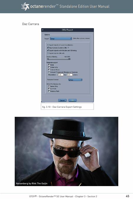
Daz Carrara
fig. 3.10 - Daz Carrara Export Settings
Heisenberg by Rikk The Gaijin

46
Standalone Edition User ManualoctanerenderTM
Chapter 4
UsingOctaneRender™
OTOY® - OctaneRender™ SE User Manual
By karba
47
Standalone Edition User ManualoctanerenderTM
OTOY® - OctaneRender™ SE User Manual - Chapter 4 - Section 1
1. Using the Preview Macro
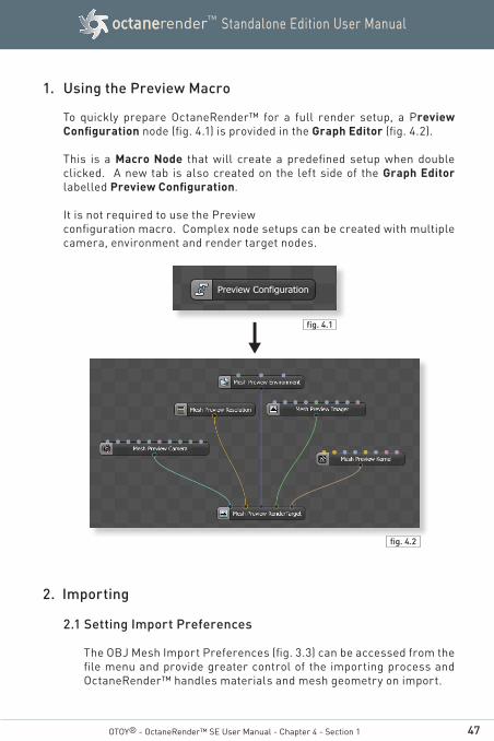
To quickly prepare OctaneRender™ for a full render setup, a Preview Configuration node (fig. 4.1) is provided in the Graph Editor (fig. 4.2).
This is a Macro Node that will create a predefined setup when double clicked. A new tab is also created on the left side of the Graph Editor labelled Preview Configuration.
It is not required to use the Preview configuration macro. Complex node setups can be created with multiple camera, environment and render target nodes.
2. Importing
2.1 Setting Import Preferences
The OBJ Mesh Import Preferences (fig. 3.3) can be accessed from the file menu and provide greater control of the importing process and OctaneRender™ handles materials and mesh geometry on import.
fig. 4.1
fig. 4.2

48
Standalone Edition User ManualoctanerenderTM
Override settings during individual import— Sets whether the scene or OctaneRender™ settings should be used.
Import MTL file —Determines whether OctaneRender™ imports any materials that were stored in the MTL file associated with the imported OBJ file.
Material Types—Allows the user to specify what material types are imported.
Import Image Textures—Uses the image textures as specified in the MTL file.
Texture Types—Allows the user to determine the data type of im-ported images.
Object Smoothing—Allows the user to set preferences related to material smoothing including using supplied vertex normals and smoothgroups.
Meta Objects—Allows the user to set a material in their modeling software to set the camera position in OctaneRender™. The ob-ject with the material specified in the Transform Material Name field will be used to position the camera.
OTOY® - OctaneRender™ SE User Manual - Chapter 4 - Section 2
fig. 4.3
49
Standalone Edition User ManualoctanerenderTM
OTOY® - OctaneRender™ SE User Manual - Chapter 4 - Section 2.2
2.2 Importing the Scene
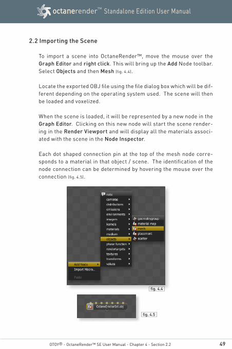
To import a scene into OctaneRender™, move the mouse over the Graph Editor and right click. This will bring up the Add Node toolbar. Select Objects and then Mesh (fig. 4.4).
Locate the exported OBJ file using the file dialog box which will be dif-ferent depending on the operating system used. The scene will then be loaded and voxelized.
When the scene is loaded, it will be represented by a new node in the Graph Editor. Clicking on this new node will start the scene render-ing in the Render Viewport and will display all the materials associ-ated with the scene in the Node Inspector.
Each dot shaped connection pin at the top of the mesh node corre-sponds to a material in that object / scene. The identification of the node connection can be determined by hovering the mouse over the connection (fig. 4.5).
fig. 4.4
fig. 4.5
50
Standalone Edition User ManualoctanerenderTM
3. Navigating the Scene
OctaneRender™ provides a unique, refreshing and exciting rendering experience due to the ability to interact with the scene with final render quality. This interactivity allows for renders that might not be possible with traditional render engines. The user can continue to hunt for that perfect camera angle where all the reflections of the lights are just right or they can continue to adjust the DOF in real-time.
The Render Viewport can be manipulated like traditional 3D viewports with rotation, panning and zooming controls.
Navigating in the Render Viewport (While holding your mouse over the Render Viewport):
Rotate: Left Mouse Button Zoom: Mouse Wheel / Middle Mouse Button Pan: Right Mouse
If the scene navigation is too slow, hold the SHIFT key while navigating with the mouse.
Controls for the camera multiplier and mouse presets can be set through the Menu Preferences --> Controls tab.
Sub-sampling Settings
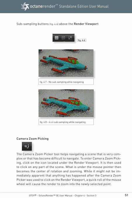
Using sub-sampling allows for smoother navigation of the scene by re-ducing the render resolution. In order to improve navigation at the cost of visual quality, 2x2 or 4x4 sub-sampling settings can be adjusted by us-ing the checkerboard buttons under the Render Viewport. The reduced settings apply when the scene is being navigated and then returns to the render settings after navigation has stopped. Figures 4.7 and 4.8 show the difference between navigating with no sub-sampling versus navigat-ing with 4x4 sub-sampling.
OTOY® - OctaneRender™ SE User Manual - Chapter 4 - Section 3
51
Standalone Edition User ManualoctanerenderTM
Sub-sampling buttons (fig. 4.6) above the Render Viewport
Camera Zoom Picking
The Camera Zoom Picker tool helps navigating a scene that is very com-plex or that has become difficult to navigate. To enter Camera Zoom Pick-ing, click on the icon located under the Render Viewport. It is then used to click on any part of the scene. What is under the mouse pointer then becomes the center of rotation and zooming. While it might not be im-mediately apparent that anything has happened after the Camera Zoom Picker was used to click on the Render Viewport, a quick roll of the mouse wheel will cause the render to zoom into the newly selected point.
OTOY® - OctaneRender™ SE User Manual - Chapter 4 - Section 3
fig. 4.7 - No sub-sampling while navigating
fig. 4.8 - 4 x 4 sub-sampling while navigating
fig. 4.6
52
Standalone Edition User ManualoctanerenderTM
OTOY® - OctaneRender™ SE User Manual - Chapter 4 - Section 3
Camera Reset
The Camera Reset button allows the camera to be reset back to the origi-nal position. If the scene was just created from an imported object, then the Camera Reset button will reset the camera position to the default coordinates similar to when the object was just imported. If the scene was saved as an Octane Scene File, then the camera would be reset to the position of the Octane Scene File.
Recenter View
The Recenter view button centers the render in the render view port. This is useful if the render was moved and is no longer visible or centered.
4. Render Settings
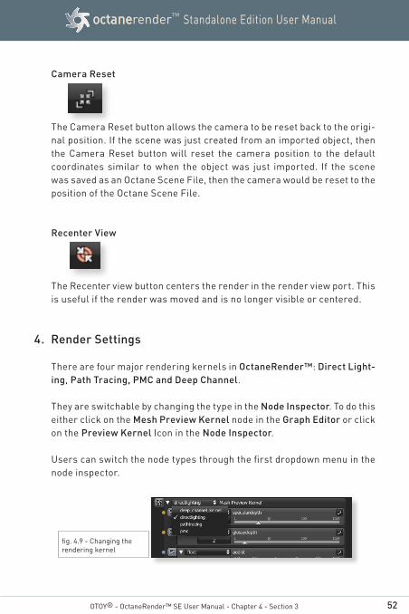
There are four major rendering kernels in OctaneRender™: Direct Light-ing, Path Tracing, PMC and Deep Channel.
They are switchable by changing the type in the Node Inspector. To do this either click on the Mesh Preview Kernel node in the Graph Editor or click on the Preview Kernel Icon in the Node Inspector.
Users can switch the node types through the first dropdown menu in the node inspector.
fig. 4.9 - Changing the rendering kernel
53
Standalone Edition User ManualoctanerenderTM
4.1 Direct Lighting
Direct Lighting is used for faster preview rendering. Direct Lighting is not unbiased but is useful when creating quick animations or ren-ders.
Specular Depth (speculardepth)
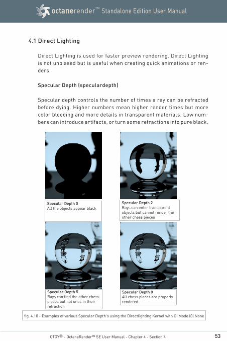
Specular depth controls the number of times a ray can be refracted before dying. Higher numbers mean higher render times but more color bleeding and more details in transparent materials. Low num-bers can introduce artifacts, or turn some refractions into pure black.
OTOY® - OctaneRender™ SE User Manual - Chapter 4 - Section 4
fig. 4.10 - Examples of various Specular Depth's using the Directlighting Kernel with GI Mode (0) None
Specular Depth 0All the objects appear black
Specular Depth 2Rays can enter transparent objects but cannot render the other chess pieces
Specular Depth 5Rays can find the other chess pieces but not ones in their refraction
Specular Depth 8All chess pieces are properly rendered
54
Standalone Edition User ManualoctanerenderTM
OTOY® - OctaneRender™ SE User Manual - Chapter 4 - Section 4
Glossy Depth (glossydepth)Glossy depth controls the number of times a ray can be reflected be-fore dying. Higher numbers mean higher render time. Low numbers under "4" can introduce artifacts, or turn some reflections into pure black. You should setup this setting based on the complexity of the scene you are working on, and especially based on how many reflec-tive parallel surfaces you have.
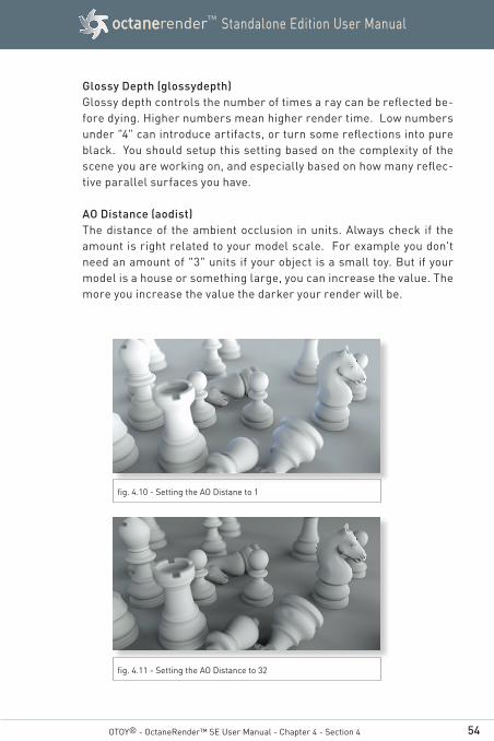
AO Distance (aodist)The distance of the ambient occlusion in units. Always check if the amount is right related to your model scale. For example you don't need an amount of "3" units if your object is a small toy. But if your model is a house or something large, you can increase the value. The more you increase the value the darker your render will be.
fig. 4.10 - Setting the AO Distane to 1
fig. 4.11 - Setting the AO Distance to 32
55
Standalone Edition User ManualoctanerenderTM
OTOY® - OctaneRender™ SE User Manual - Chapter 4 - Section 4
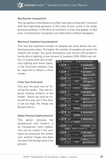
Ray Epsilon (rayepsilon)
The ray epsilon is the distance to offset new rays so they don't intersect with the originating geometry. If the scale of your scene is too large, precision artifacts in the form of concentric circles may appear. In that case, increasing the ray epsilon can make these artifacts disappear.
Maximum Samples (maxsamples)
This sets the maximum number of samples per pixel before the ren-dering process stops. The higher the number of samples per pixel, the cleaner the render. For quick animations and scenes with predomi-nantly direct lighting, a low amount of samples (500-1000) may suf-fice. In scenes with lots of indi-rect lighting and mesh lights, a few thousand samples may be required to obtain a clean render.
Filter Size (filtersize)
This sets the pixel size for fil-tering the render. This can im-prove aliasing artifacts in the render. Noise can also be re-duced this way, but if the filter is set too high, the image can become blurry.
Alpha Channel (alphachannel)
This option removes the background and renders it as transparant (zero alpha). This can be useful if the user wants to composite the render over another image and does not want the background to be present.
56
Standalone Edition User ManualoctanerenderTM
OTOY® - OctaneRender™ SE User Manual - Chapter 4 - Section 4
Keep Environment (keep_environment)
This option is used in conjuction with the Alpha Channel setting. It al-lows the background to be rendered with zero alpha but is still visible in the final render. This allows even further flexiblity in compositing images.
Alpha Shadows (alphashadows)
This setting allows any object with transparency (specular materials, materials with opacity settings and alpha channels) to cast a proper shadow instead of behaving as a solid object.
GI Mode
There are five different Global Illumination modes in the Direct Lighting Kernel:
None(0)Only direct lighting from the sun or area lights is included. Shadowed areas receive no contribution and will be black.
Ambient(1)Use a simple ambient colour from the environment above.
Sample Environment (2)Use a simple ambient colour from the environment/horizon.
Together with ambient and none, these modes are all very fast, as no Monte Carlo sampling is required. These give a very unrealistic, classic z-buffer/whitted raytracing style look, but are very fast, and very handy for interactive tuning of complex scenes or on slow hardware.

57
Standalone Edition User ManualoctanerenderTM
OTOY® - OctaneRender™ SE User Manual - Chapter 4 - Section 4
Ambient Occlusion (3)Standard ambient occlusion. This mode can often provide re-alistic images but offers no color bleeding.
Diffuse (4)Indirect diffuse, with a configuration to set the number of in-direct diffuse bounces to include. This gives a GI quality that is in between Ambient Occlusion and pathtracing, without caustics and a decent realistic quality (better than AO), but much faster than pathtracing/PMC.
It is very good for quick finals and animations. It is similar in some ways to 'bruteforce' indirect GI in other engines.
Diffuse Depth
Gives the maximum number of diffuse reflections if GI Mode is set to Diffuse (4)
Russian Roulette Probability (rrprob)
In path tracing, maxdepth is the maximum amount of bounces a ray can make, but, after 3 bounces, there is a 50 % chance that the ray is killed, if you set the rrprob parameter to 0.5. In practice it will rarely exceed more than 16-20 bounces once every million pixel samples (generating a firefly usually).
If the rrprob is set to 0, it uses a automatic setting. If it is set to any-thing else, the user directly controls the probability the ray is ended at random after 3 bounces and so forth.
58
Standalone Edition User ManualoctanerenderTM
OTOY® - OctaneRender™ SE User Manual - Chapter 4 - Section 4
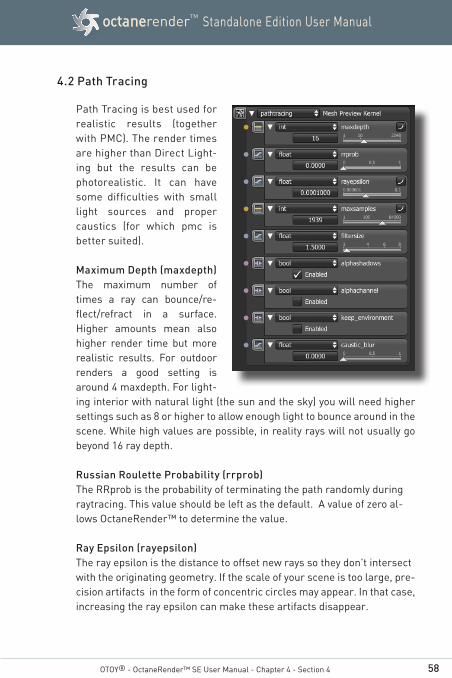
4.2 Path Tracing
Path Tracing is best used for realistic results (together with PMC). The render times are higher than Direct Light-ing but the results can be photorealistic. It can have some difficulties with small light sources and proper caustics (for which pmc is better suited).
Maximum Depth (maxdepth)The maximum number of times a ray can bounce/re-flect/refract in a surface. Higher amounts mean also higher render time but more realistic results. For outdoor renders a good setting is around 4 maxdepth. For light-ing interior with natural light (the sun and the sky) you will need higher settings such as 8 or higher to allow enough light to bounce around in the scene. While high values are possible, in reality rays will not usually go beyond 16 ray depth.
Russian Roulette Probability (rrprob)The RRprob is the probability of terminating the path randomly during raytracing. This value should be left as the default. A value of zero al-lows OctaneRender™ to determine the value.
Ray Epsilon (rayepsilon)The ray epsilon is the distance to offset new rays so they don't intersect with the originating geometry. If the scale of your scene is too large, pre-cision artifacts in the form of concentric circles may appear. In that case, increasing the ray epsilon can make these artifacts disappear.
59
Standalone Edition User ManualoctanerenderTM
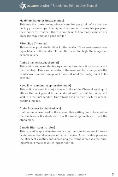
Maximum Samples (maxsamples)This sets the maximum number of samples per pixel before the ren-dering process stops. The higher the number of samples per pixel, the cleaner the render. There is no rule as to how many samples per pixel are required for a good render.
Filter Size (filtersize)This sets the pixel size for filter for the render. This can improve alias-ing artifacts in the render. If the filter is set too high, the image can become blurry.
Alpha Channel (alphachannel)This option removes the background and renders it as transparant (zero alpha). This can be useful if the user wants to composite the render over another image and does not want the background to be present.
Keep Environment (keep_environment)This option is used in conjuction with the Alpha Channel setting. It allows the background to be rendered with zero alpha but is still visible in the final render. This allows even further flexiblity in com-positing images.
Alpha Shadows (alphashadows)If alpha maps are used in the scene, this setting controls whether the shadows will calculated from the mesh geometry or from the alpha map.
Caustic Blur (caustic_blur)This is used to approximate caustics on rough surfaces and increase or decrease the sharpness of caustic noise. A zero value provides the sharpest caustics and increasing this value increases the blur-ing effect to make caustics appear softer.
OTOY® - OctaneRender™ SE User Manual - Chapter 4 - Section 4

60
Standalone Edition User ManualoctanerenderTM
OTOY® - OctaneRender™ SE User Manual - Chapter 4 - Section 4
4.3 PMC
PMC is a custom mutating unbiased kernel written for GPUs. It allows for com-plex caustics and lighting to be resolved.
Maximum Depth (maxdepth)
The maximum number of times a ray can bounce/reflect/refract in a sur-face. Higher amounts mean also higher render time but more realistic results. For outdoor renders a good setting is around 4 maxdepth. For lighting in-terior with natural light (the sun and the sky) you will need higher settings such as 8 or higher. While high values are possible, in reality rays will not usually go beyond 16 ray depth.
Russian Roulette Probability (rrprob)
The RRprob is the probability of terminating the path randomly dur-ing raytracing. This value should be left as the default. A value of zero allows OctaneRender™ to determine the value.
Ray Epsilon (rayepsilon)
The ray epsilon is the distance to offset new rays so they don't in-tersect with the originating geometry. This value should be left as the default.
61
Standalone Edition User ManualoctanerenderTM
Exploration Strength (exporation_strength)
This specifies how long the kernel investigates good paths before it tries to find a new path. Low values can create a noisy image while larger values can create a splotchy image.
Direct Light Importance (direct_light_importance)
The direct light importance makes the kernel focus more on paths with indirect light. For example, imagine sunlight through a window that creates a bright spot on the floor. If the direct light importance is 1, the kernel would sample this area a lot, although it becomes clean very quickly. If the direct light importance is reduced, the kernel reduces its efforts to sample that area and focuses more on more tricky areas that are harded to render.
Max Rejects (maxrejects)
This can control the "bias" of the render. By reducing the value, the result will be more biased, but the render time will be shorter.
Maximum Samples (maxsamples)
This sets the maximum number of samples per pixel before the ren-dering process stops. The higher the number of samples per pixel, the cleaner the render.
Filter Size (filtersize)
This sets the pixel size for filter for the render. This can improve alias-ing artifacts in the render. If the filter is set too high, the image can become blurry.
Alpha Shadows (alphashadows)
If alpha maps are used in the scene, this setting controls whether the shadows will be calculated from the mesh geometry or from the alpha map.
OTOY® - OctaneRender™ SE User Manual - Chapter 4 - Section 4
62
Standalone Edition User ManualoctanerenderTM
Alpha Channel (alphachannel)
This option removes the background and renders it as transparant (zero alpha). This can be useful if the user wants to composite the render over another image and does not want the background to be present.
Keep Environment (keep_environment)
This option is used in conjuction with the Alpha Channel setting. It allows the background to be rendered with zero alpha but is still visible in the final render. This allows even further flexiblity in com-positing images.
Caustic Blur (caustic_blur)
This is used to approximate caustics on rough surfaces and increase or decrease the sharpness of caustic noise. A zero value provides the sharpest caustics and increasing this value increases the blur-ing effect to make caustics appear softer.
OTOY® - OctaneRender™ SE User Manual - Chapter 4 - Section 4
63
Standalone Edition User ManualoctanerenderTM
OTOY® - OctaneRender™ SE User Manual - Chapter 4 - Section 4
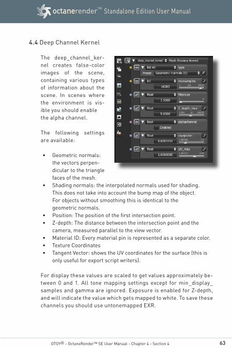
4.4 Deep Channel Kernel
The deep_channel_ker-nel creates false-color images of the scene, containing various types of information about the scene. In scenes where the environment is vis-ible you should enable the alpha channel.
The following settings are available:
• Geometric normals: the vectors perpen-dicular to the triangle faces of the mesh.
• Shading normals: the interpolated normals used for shading. This does not take into account the bump map of the object. For objects without smoothing this is identical to the geometric normals.
• Position: The position of the first intersection point.• Z-depth: The distance between the intersection point and the
camera, measured parallel to the view vector.• Material ID: Every material pin is represented as a separate color.• Texture Coordinates• Tangent Vector: shows the UV coordinates for the surface (this is
only useful for export script writers).
For display these values are scaled to get values approximately be-tween 0 and 1. All tone mapping settings except for min_display_samples and gamma are ignored. Exposure is enabled for Z-depth, and will indicate the value which gets mapped to white. To save these channels you should use untonemapped EXR.

64
Standalone Edition User ManualoctanerenderTM
Maximum Samples (maxsamples)
This sets the maximum number of samples per pixel before the ren-dering process stops. The higher the number of samples per pixel, the cleaner the render. There is no rule as to how many samples per pixel are required for a good render.
Filter Size (filtersize)
This sets the pixel size for filter for the render. This can improve alias-ing artifacts in the render. If the filter is set too high, the image can become blurry.
Maximum Z-Depth (z_depth_max)
Gives the maximum z-depth that can be shown.
Alpha Channel (alphachannel)
This option removes the background and renders it as transparant (zero alpha). This can be useful if the user wants to composite the render over another image and does not want the background to be present.
Ray Epsilon (rayepsilon)
The ray epsilon is the distance to offset new rays so they don't in-tersect with the originating geometry. This value should be left as the default.
Maximum UV value (uv_max)
Gives the maximum value that can be shown for the texture coordi-nates.
OTOY® - OctaneRender™ SE User Manual - Chapter 4 - Section 4
65
Standalone Edition User ManualoctanerenderTM
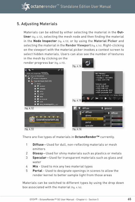
5. Adjusting Materials
Materials can be edited by either selecting the material in the Out-liner (fig. 4.12), selecting the mesh node and then finding the material in the Node Inspector (fig. 4.13), or by using the Material Picker and selecting the material in the Render Viewport (fig. 4.14). Right-clicking on the viewport with the material picker invokes a context screen to select hidden materials. Users can also see the number of textures
OTOY® - OctaneRender™ SE User Manual - Chapter 4 - Section 5
fig. 4.13
fig. 4.14
fig. 4.12
fig. 4.16
in the mesh by clicking on the render progress bar (fig. 4.15).
There are five types of materials in OctaneRender™ currently.
1 Diffuse—Used for dull, non-reflecting materials or mesh emitters
2 Glossy—Used for shiny materials such as plastics or metals3 Specular—Used for transparent materials such as glass and
water4 Mix - Used to mix any two material types5 Portal - Used to designate openings in scenes to allow the
render kernel to better sample light from those areas
Materials can be switched to different types by using the drop down box associated with the material (fig. 4.16).
fig. 4.15

66
Standalone Edition User ManualoctanerenderTM
5.1 Working with Material Data
All of the materials can be adjusted by using sub parameters. These parameters can be set to various data types / nodes to provide for flexible rendering. They can be broken into two main classes: Tex-tures and Values.
Textures are used to cre-ate and manipulate the colour and appearance of the actual material. There are four different Texture types: Colours, Generators, Images and Mappings.
Values are used any-where only numeric input is required.
Any parameter that requires a Value can not use a Texture type as it’s source and a Texture can not accept a Value as its source.
5.2 Values
The Values available are:
Bool—A value that can be either true or false
Float—A single value slider adjusts the value
Float2—Two value sliders adjusts the value (X,Y). The range of the values are dictated by the parameter it is controlling.
Float3—Three value sliders adjusts the value (X,Y,Z). The range of the values are dictated by the parameter it is controlling.
Float3DaylightSystem—Used for setting all the properties of the Sun /
Sky Environment.
OTOY® - OctaneRender™ SE User Manual - Chapter 4 - Section 5
67
Standalone Edition User ManualoctanerenderTM
Int—A single value slider that adjusts the value in whole integer steps
Int2—Two value sliders adjust the value of (X,Y) in whole integer steps
Int2resolution—Two parameters adjust the resolution of the render
int2XY - Two value sliders adjust the value of (X,Y) in whole integers steps
5.3 Texture Types
The Texture types allow for creating very flexible materials. There are four main types of Texture Node Types:
Colours: Colour textures provide methods of applying a colour to a material.
Generators: Generator textures are used to actually create or modu-late other textures. They are grey scale.
Images: Image textures use image files to create the texture.
Mappings: Mappings are Nodes that allow mixing and manipulation of other texture nodes.
OTOY® - OctaneRender™ SE User Manual - Chapter 4 - Section 5

68
Standalone Edition User ManualoctanerenderTM
5.3.1 Colour Textures
RGBspectrum—The texture is based on the RGB colour that is selected
GaussianSpectrum— The texture is based on a Gaussian dis-tribution spectrum. The wavelength is used to set the center of the spectrum and the width is used to set how wide the curve is. The narrower the width, the more pure and saturated the colour.
5.3.2 Image Textures
In order to properly utilize Image Textures, the mesh must be UV mapped prior to export from the Modelling software.
FloatImage—The image is interpreted as gray scale even if it is a full colour image, thus saving GPU ram. The Invert checkbox can be used to invert the image (useful for bump and opacity maps.)
Image—An image texture is used for the parameter (mesh must be UV mapped prior to export to properly use the Image type). The image is interpreted as being full colour even if it is a grey scale image, and therefore taking up more GPU memory.
AlphaImage - An alpha image utilizes the images native Alpha Channel to provide transparency. This type will only accept PNG and TIF image types.
OTOY® - OctaneRender™ SE User Manual - Chapter 4 - Section 5
When to use Floatimage versus Image Data Type?
There are some parameters where full colour data is not used (or useful). If a full colour image is loaded, it can take much more memory in the GPU than a grey scale image, even though the user only really wants the grey scale data. Since memory management is very critical for GPU rendering, the Floatimage type allows a user to load a full colour texture but it will be interpreted as a grey scale image and therefore use less video ram. If the full colour data is needed then use the Image data type (normal maps, diffuse maps)

69
Standalone Edition User ManualoctanerenderTM
OTOY® - OctaneRender™ SE User Manual - Chapter 4 - Section 5
5.3.3 Texture Generators
Texture Generators are used to create patterns that can be used alone or in combination with the Mapping and Colour textures to create memory-efficient, procedural textures. Procedural Tex-tures can be used to create textures, bump maps and other ad-vanced materials with minimal impact to GPU memory. It is therefore advantageous to explore creating materials using these textures before resorting to image based textures.
The current types of generators include:
ChecksMarbleRidged FractalSaw WaveSine WaveTriangle WaveTurbulence
Generator Texture Examples
Procedural Textures can be used to create textures, bump maps and other advanced materials with minimal impact to GPU memo-ry. It is therefore advantageous to explore creating materials us-ing these textures before resorting to image based textures.
70
Standalone Edition User ManualoctanerenderTM
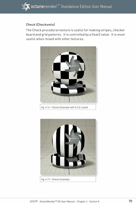
Check (Checksmix)
The Check procedural texture is useful for making stripes, checker board and grid patterns. It is controlled by a float3 value. It is most useful when mixed with other textures.
OTOY® - OctaneRender™ SE User Manual - Chapter 4 - Section 5
fig. 4.16 - Checks Example with X,Y,Z scaled
fig. 4.17 - Checks Example
71
Standalone Edition User ManualoctanerenderTM
OTOY® - OctaneRender™ SE User Manual - Chapter 4 - Section 5
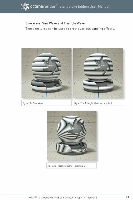
Sine Wave, Saw Wave and Triangle Wave
These textures can be used to create various banding effects.
fig. 4.18 - Saw Wave fig. 4.19 - Triangle Wave - example 1
fig. 4.20 - Triangle Wave - example 2
72
Standalone Edition User ManualoctanerenderTM
OTOY® - OctaneRender™ SE User Manual - Chapter 4 - Section 5
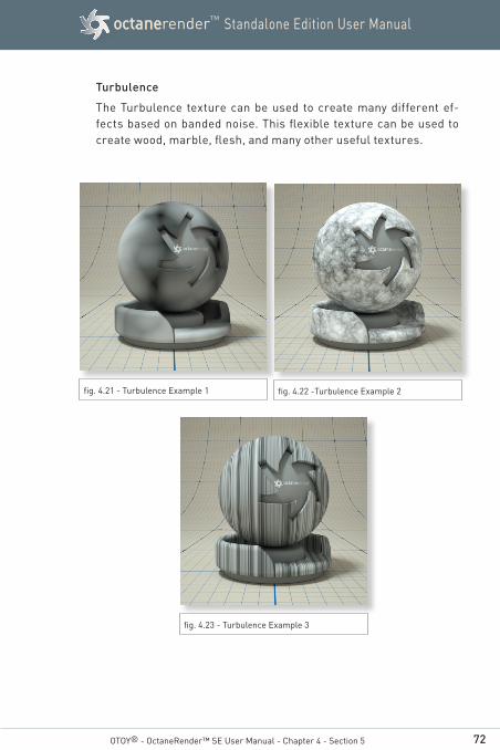
Turbulence
The Turbulence texture can be used to create many different ef-fects based on banded noise. This flexible texture can be used to create wood, marble, flesh, and many other useful textures.
fig. 4.21 - Turbulence Example 1 fig. 4.22 -Turbulence Example 2
fig. 4.23 - Turbulence Example 3
73
Standalone Edition User ManualoctanerenderTM
OTOY® - OctaneRender™ SE User Manual - Chapter 4 - Section 5
Mapping Texture Examples
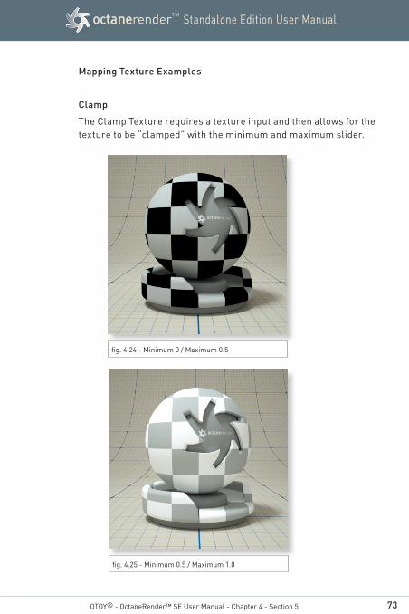
Clamp
The Clamp Texture requires a texture input and then allows for the texture to be “clamped” with the minimum and maximum slider.
fig. 4.24 - Minimum 0 / Maximum 0.5
fig. 4.25 - Minimum 0.5 / Maximum 1.0
74
Standalone Edition User ManualoctanerenderTM
OTOY® - OctaneRender™ SE User Manual - Chapter 4 - Section 5
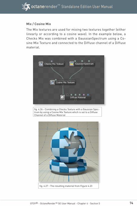
Mix / Cosine Mix
The Mix textures are used for mixing two textures together (either linearly or according to a cosine wave). In the example below, a Checks Mix was combined with a GaussianSpectrum using a Co-sine Mix Texture and connected to the Diffuse channel of a Diffuse material.
fig. 4.26 - Combining a Checks Texture with a Gaussian Spec-trum by using a Cosine Mix Texture which is set to a Diffuse Channel of a Diffuse Material
fig. 4.27 - The resulting material from Figure 4.23
75
Standalone Edition User ManualoctanerenderTM
OTOY® - OctaneRender™ SE User Manual - Chapter 4 - Section 5
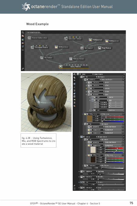
Wood Example
fig. 4.28 - Using Turbulence, Mix, and RGB Spectrums to cre-ate a wood material

76
Standalone Edition User ManualoctanerenderTM
5.3.4 Fall Off Texture Map
The fall off map is a texture node typically used to control the blend of two materials depend-ing on the viewing angle of the materials geometry.
Normal This is the value/lightness (0 to 1) of the map at straight on viewing angles. When used as an input to a mix material node, the normal is the spectral shade value between material 0 and material 1.
Grazing This is the value/lightness (0 to 1) of the map at grazing angles. When used as an input to a mix material node, the grazing is the spectral shade value between material 0 and material 1.
Falloff Index The relative amount of the two values (normal and grazing). 0.1 will lead to almost complete coverage by the grazing value regardless of viewing angle, where as 15 will lead to complete coverage by the normal value.
OTOY® - OctaneRender™ SE User Manual - Chapter 4 - Section 5
77
Standalone Edition User ManualoctanerenderTM
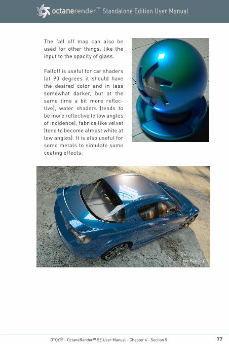
The fall off map can also be used for other things, like the input to the opacity of glass.
Falloff is useful for car shaders (at 90 degrees it should have the desired color and in less somewhat darker, but at the same time a bit more reflec-tive), water shaders (tends to be more reflective to low angles of incidence), fabrics like velvet (tend to become almost white at low angles). It is also useful for some metals to simulate some coating effects.
By Karba
OTOY® - OctaneRender™ SE User Manual - Chapter 4 - Section 5
78
Standalone Edition User ManualoctanerenderTM
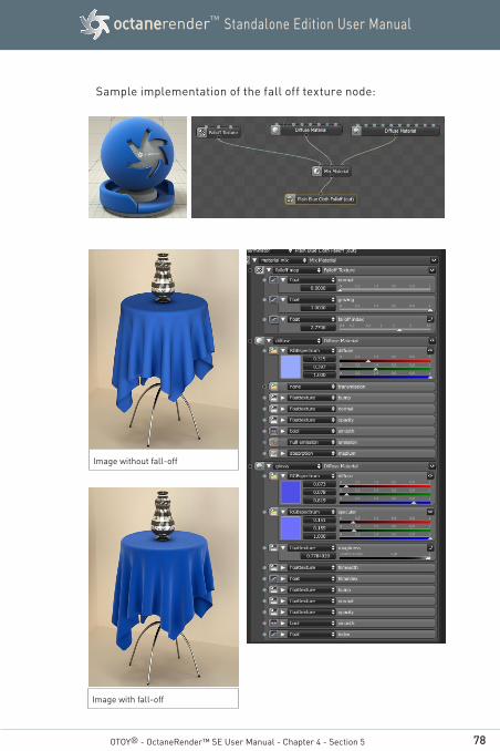
Sample implementation of the fall off texture node:
Image without fall-off
Image with fall-off
OTOY® - OctaneRender™ SE User Manual - Chapter 4 - Section 5
79
Standalone Edition User ManualoctanerenderTM
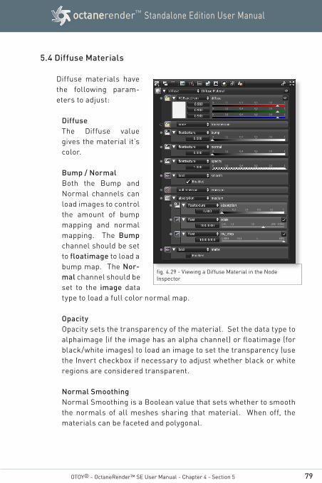
5.4 Diffuse Materials
Diffuse materials have the following param-eters to adjust:
DiffuseThe Diffuse value gives the material it’s color.
Bump / NormalBoth the Bump and Normal channels can load images to control the amount of bump mapping and normal mapping. The Bump channel should be set to floatimage to load a bump map. The Nor-mal channel should be set to the image data type to load a full color normal map.
OpacityOpacity sets the transparency of the material. Set the data type to alphaimage (if the image has an alpha channel) or floatimage (for black/white images) to load an image to set the transparency (use the Invert checkbox if necessary to adjust whether black or white regions are considered transparent.
Normal SmoothingNormal Smoothing is a Boolean value that sets whether to smooth the normals of all meshes sharing that material. When off, the materials can be faceted and polygonal.
OTOY® - OctaneRender™ SE User Manual - Chapter 4 - Section 5
fig. 4.29 - Viewing a Diffuse Material in the Node Inspector
80
Standalone Edition User ManualoctanerenderTM
OTOY® - OctaneRender™ SE User Manual - Chapter 4 - Section 5
EmissionThe Emission setting controls whether the material acts as a light source.
MatteThis is a bolean value to enable or disable a matte mask of a diffuse material.
For applying absorption, SubSurface Scattering and emission on Diffuse Material, refer to Chapter 5 Section 5.9.
5.5 Glossy Materials
Glossy materials have these parameters to adjust:
Diffuse (diffuse)The value gives the material its color.
Specularity (specular)The value determines the amount of specularity on the mesh.
Roughness (roughness)The roughness determines the amount of reflection that will be present. A low roughness value will create blurry reflections and a high value will produce a mirror like reflection. Bump / NormalBoth the Bump and Normal channels can load images to control the amount of bump mapping and normal mapping (respectively.) The Bump channel should be set to floatimage to load a bump map. The Normal channel should be set to the image data type to load a full color normal map.
Film Width (filmwidth)This controls the thickness of a optical, thin film on the material. This is useful in creating rainbow or oil slick effects.
81
Standalone Edition User ManualoctanerenderTM
OTOY® - OctaneRender™ SE User Manual - Chapter 4 - Section 5
Film Index (filmindex)This controls the Index of Refraction of the thin film.
Opacity (opacity)Opacity sets the transparency of the material. Set the data type to alphaimage(if the image has an alpha channel) or floatimage(for black/white images) to load an image to set the transparency (use the Invert checkbox if necessary to adjust whether black or white regions are considered transparent.
Normal Smoothing (smooth)Normal Smoothing is a Boolean value that sets whether to smooth the normals of all meshes sharing that material. When off, the ma-terials can be faceted and polygonal.
Index of Refraction (index)Index of refraction sets the fresnel effect applied on the glossy material. Setting a value smaller than 1.0 will disable the fresnel effect, so the glossy color will be the color in the glossy input pin, regardless of viewing angle. When selecting a value of 1.0 or big-ger, the glossy reflection color will be modulated according to the fresnel law: at grazing angles the color will be the color set in the glossy input pin, at perpendicular angles it will be darker. Fresnel reflection produced becomes stronger as the index of refraction is set higher.
If you have a measured index of refraction, set the glossy color to 1.0.
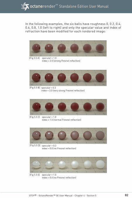
82
Standalone Edition User ManualoctanerenderTM
OTOY® - OctaneRender™ SE User Manual - Chapter 4 - Section 5
specular = 1.0index = 2.0 (strong Fresnel reflection)
specular = 0.3index = 3.0 (very strong Fresnel reflection)
specular = 1.0index = 1.5 (normal Fresnel reflection)
specular = 0.3index = 0.0 (no Fresnel reflection)
specular = 1.0index = 0.0 (no Fresnel reflection)
[Fig 5.5 A]
[Fig 5.5 B]
[Fig 5.5 C]
[Fig 5.5 D]
[Fig 5.5 E]
In the following examples, the six balls have roughness 0, 0.2, 0.4, 0.6, 0.8, 1.0 (left to right) and only the specular value and index of refraction have been modified for each rendered image:
83
Standalone Edition User ManualoctanerenderTM
OTOY® - OctaneRender™ SE User Manual - Chapter 4 - Section 5
5.6 Specular (Glass) materials
Specular materials have these parameters to adjust:
Reflection (reflection)The Reflection value determines the glossiness of the mesh.
Transmission (transmission)The Transmission value gives the base color to the mesh.
Index of Refraction (index)The Index represents the Index of Refraction of the material. Standard values of Index of Refraction (IOR) can be readily found via searching the internet. Glass typically has a value of 1.53 and water 1.33.
Film Width (filmwidth)This controls the thickness of a optical, thin film on the material. This is useful in creating rainbow or oil slick effects.
Film Index (filmindex)This controls the Index of Refraction of the thin film.Bump / NormalBoth the Bump and Normal channels can load images to control the amount of bump mapping and normal mapping (respectively.) The Bump channel should be set to floatimage to load a bump map. The Normal channel should be set to the image data type to load a full color normal map.
Opacity (opacity)Opacity sets the transparency of the material. Set the data type to alphaimage(if the image has an alpha channel) or floatimage(for black/white images) to load an image to set the transparency (use the Invert checkbox if necessary to adjust whether black or white regions are considered transparent.

84
Standalone Edition User ManualoctanerenderTM
OTOY® - OctaneRender™ SE User Manual - Chapter 4 - Section 5
Normal Smoothing (smooth)Normal Smoothing is a Boolean value that sets whether to smooth the normals of all meshes sharing that material. When off, the ma-terials can be faceted and polygonal.
Dispersion Coefficient (dispersion_coefficient_B)The dispersion in OctaneRender™ is based on Cauchy's equation which has two terms: A which is the index of refraction and B which is the dispersion coefficient. Increasing the value increases the amount of coloration and dispersion in the object and in caustics.
Absorption or Scattering Medium (medium)
Absorption MediumAbsorption means that the material slightly absorbs light while passing through. The color resulting from this absorption is dependent on the distance light travels through the material. With increased distance it will get darker, and if the absorption is colored it will get more saturated.
Scattering MediumSimilar to the absorption medium but with the option to simulate subsuburface scattering.
The scale parameter multiplies the absorption texture, allowing a wide range of values to be set more easily. For applying absorp-tion, SubSurface Scattering and emission on Specular and Glossy Materials, refer to Chapter 5 Section 5.9.
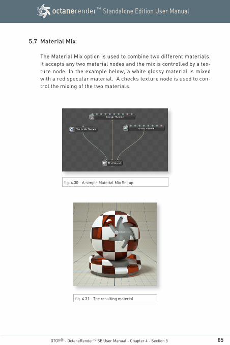
85
Standalone Edition User ManualoctanerenderTM
OTOY® - OctaneRender™ SE User Manual - Chapter 4 - Section 5
5.7 Material Mix
The Material Mix option is used to combine two different materials. It accepts any two material nodes and the mix is controlled by a tex-ture node. In the example below, a white glossy material is mixed with a red specular material. A checks texture node is used to con-trol the mixing of the two materials.
fig. 4.30 - A simple Material Mix Set up
fig. 4.31 - The resulting material
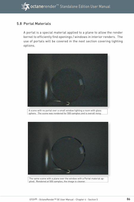
86
Standalone Edition User ManualoctanerenderTM
OTOY® - OctaneRender™ SE User Manual - Chapter 4 - Section 5
5.8 Portal Materials
A portal is a special material applied to a plane to allow the render kernel to efficiently find openings / windows in interior renders. The use of portals will be covered in the next section covering lighting options.
A scene with no portal over a small window lighting a room with glass sphere. The scene was rendered for 500 samples and is overall noisy.
The same scene with a plane over the window with a Portal material ap-plied. Rendered at 500 samples, the image is cleaner.
87
Standalone Edition User ManualoctanerenderTM
OTOY® - OctaneRender™ SE User Manual - Chapter 4 - Section 5
5.9 Using Medium Nodes
OctaneRender™ supports participating media inside objects (ab-sorption, SubSurface Scattering and emission). These settings are stored in medium nodes, which are attached to the corresponding input pin of diffuse or specular material nodes.
There are two types of medium nodes, absorption and scattering. Scattering has parameters for absorption and scattering of light passing through the medium, and emission inside the medium. Ab-sorption is a simple version with only absorption.
Rendering a medium requires the path tracing or PMC kernel, with a sufficiently large maxdepth setting. For media inside diffuse trans-mitting materials the direct light kernel with Diffuse (4) GI mode can be used as well.
Meshes
Participating media should only be added to meshes that define a closed volume, rather than planes. Using planes to model leaves of a plant with SSS will for instance not work. Using a single plane as ground plane should be OK (it will be treated as an infinively deep material). The mesh can have opaque objects nested inside, but nested participating media are not supported.
How to make a medium node work:
A specular material is the easiest: by default it is set up properly. Transmission must be nonzero; for the best effect reflection and transmission should be set to 1.0.
On diffuse materials subsurface scattering only works after they are set up with diffuse transmission.
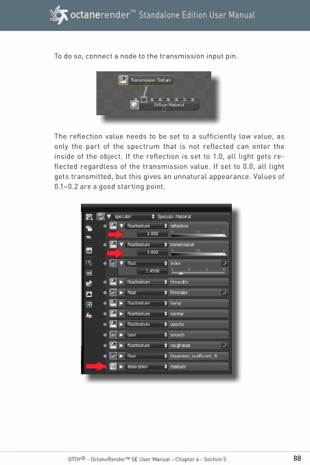
88
Standalone Edition User ManualoctanerenderTM
To do so, connect a node to the transmission input pin.
The reflection value needs to be set to a sufficiently low value, as only the part of the spectrum that is not reflected can enter the inside of the object. If the reflection is set to 1.0, all light gets re-flected regardless of the transmission value. If set to 0.0, all light gets transmitted, but this gives an unnatural appearance. Values of 0.1–0.2 are a good starting point.
OTOY® - OctaneRender™ SE User Manual - Chapter 4 - Section 5

89
Standalone Edition User ManualoctanerenderTM
OTOY® - OctaneRender™ SE User Manual - Chapter 4 - Section 5
Also, if the reflection is coloured, the transmitted light will have the complementary color (e.g. if the reflection is set to yellow, the trans-mitted light is blueish).
The transmission value works the same as in the previous releases, and is multiplied with the complement of the reflection spectrum. This should be set to a high value.
If possible, use a diffuse transmitting material

90
Standalone Edition User ManualoctanerenderTM
Medium node parameters
Absorption is controlled with the absorption texture, which defines how fast light is absorbed while passing through a medium. A setting of 0.0 means no absorption. The higher the value the faster light is absorbed by the medium. This setting is wavelength-dependent, in the following setup for example it is set to absorb blue light faster than other colors, giving the object a yellow appearance.
The absorption texture is multiplied with the scale parameter. This allows setting a wide range of values more easily.
OTOY® - OctaneRender™ SE User Manual - Chapter 4 - Section 5
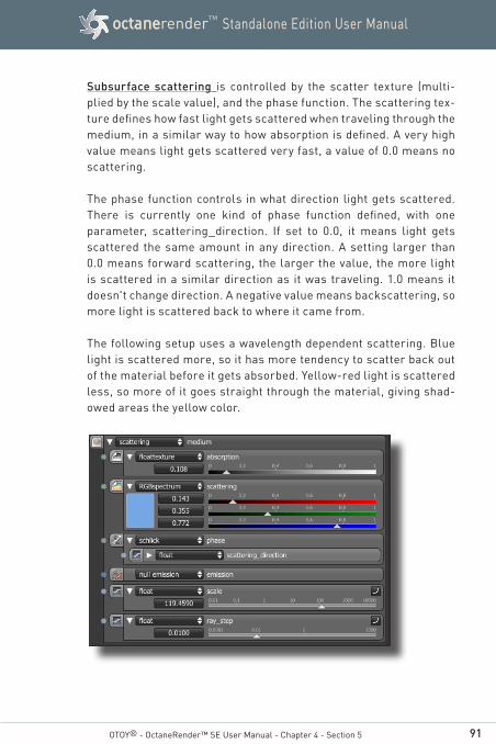
91
Standalone Edition User ManualoctanerenderTM
OTOY® - OctaneRender™ SE User Manual - Chapter 4 - Section 5
Subsurface scattering is controlled by the scatter texture (multi-plied by the scale value), and the phase function. The scattering tex-ture defines how fast light gets scattered when traveling through the medium, in a similar way to how absorption is defined. A very high value means light gets scattered very fast, a value of 0.0 means no scattering.
The phase function controls in what direction light gets scattered. There is currently one kind of phase function defined, with one parameter, scattering_direction. If set to 0.0, it means light gets scattered the same amount in any direction. A setting larger than 0.0 means forward scattering, the larger the value, the more light is scattered in a similar direction as it was traveling. 1.0 means it doesn't change direction. A negative value means backscattering, so more light is scattered back to where it came from.
The following setup uses a wavelength dependent scattering. Blue light is scattered more, so it has more tendency to scatter back out of the material before it gets absorbed. Yellow-red light is scattered less, so more of it goes straight through the material, giving shad-owed areas the yellow color.

92
Standalone Edition User ManualoctanerenderTM
OTOY® - OctaneRender™ SE User Manual - Chapter 4 - Section 5
Scattering inside a specular material will introduce a lot of noise. It will work best with smooth illumination.
Finally emission is defined by attaching an emission node to the emission input pin. When connecting an emission node to a medium node, it defines emission inside the volume instead of at the sur-face of the object. The power parameter gets a different meaning: it controls how fast the radiance along a ray increases while traveling through the volume, and not the total power. It is not multiplied with the scale parameter.
This effect works best with large and not too bright objects, very small bright objects will create a lot of noise.
The following image shows a normal mesh emitter (left) and a vol-ume emission (right). The emitter in the right side has specular ma-terial with an index of refraction of 1.0 (making it invisible without the emission).
The stepsize parameter allows lowering the average distance be-tween points where Octane samples the absorption, scattering and emission textures. If these textures are not constant, lowering this

93
Standalone Edition User ManualoctanerenderTM
OTOY® - OctaneRender™ SE User Manual - Chapter 4 - Section 5
parameter may improve the appearance of the material, but if set too low the ray tracing may terminate before the ray is traced back out of the material.
The priority input is currently not used.
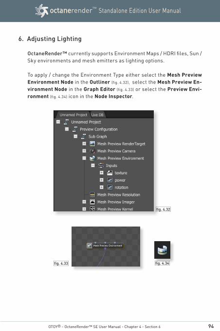
94
Standalone Edition User ManualoctanerenderTM
OTOY® - OctaneRender™ SE User Manual - Chapter 4 - Section 6
fig. 4.33 fig. 4.34
fig. 4.32
6. Adjusting Lighting
OctaneRender™ currently supports Environment Maps / HDRI files, Sun / Sky environments and mesh emitters as lighting options.
To apply / change the Environment Type either select the Mesh Preview Environment Node in the Outliner (fig. 4.32), select the Mesh Preview En-vironment Node in the Graph Editor (fig. 4.33) or select the Preview Envi-ronment (fig. 4.34) icon in the Node Inspector.
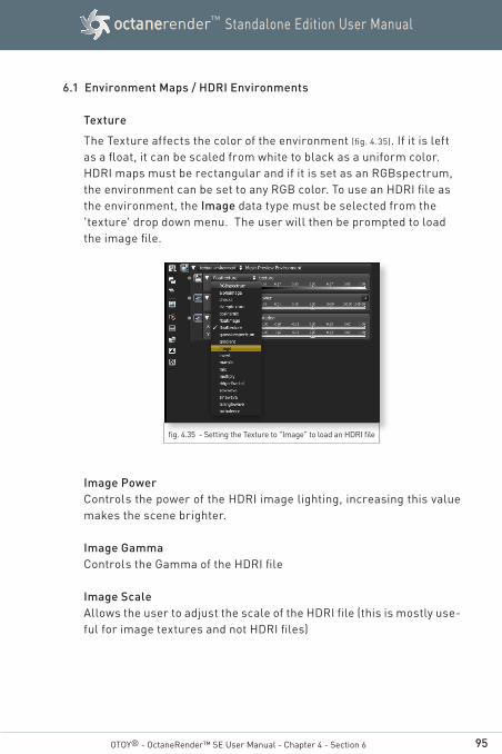
95
Standalone Edition User ManualoctanerenderTM
OTOY® - OctaneRender™ SE User Manual - Chapter 4 - Section 6
6.1 Environment Maps / HDRI Environments
Texture
The Texture affects the color of the environment (fig. 4.35). If it is left as a float, it can be scaled from white to black as a uniform color. HDRI maps must be rectangular and if it is set as an RGBspectrum, the environment can be set to any RGB color. To use an HDRI file as the environment, the Image data type must be selected from the 'texture' drop down menu. The user will then be prompted to load the image file.
fig. 4.35 - Setting the Texture to "Image" to load an HDRI file
Image Power Controls the power of the HDRI image lighting, increasing this value makes the scene brighter.
Image Gamma Controls the Gamma of the HDRI file
Image Scale Allows the user to adjust the scale of the HDRI file (this is mostly use-ful for image textures and not HDRI files)
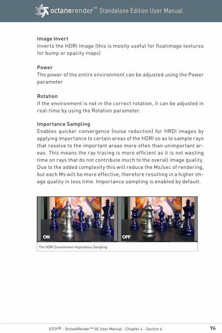
96
Standalone Edition User ManualoctanerenderTM
Image Invert Inverts the HDRI Image (this is mostly useful for floatimage textures for bump or opacity maps)
Power The power of the entire environment can be adjusted using the Power parameter
Rotation If the environment is not in the correct rotation, it can be adjusted in real-time by using the Rotation parameter.
Importance Sampling Enables quicker convergence (noise reduction) for HRDI images by applying importance to certain areas of the HDRI so as to sample rays that resolve to the important areas more often than unimportant ar-eas. This means the ray tracing is more efficient as it is not wasting time on rays that do not contribute much to the overall image quality. Due to the added complexity this will reduce the Ms/sec of rendering, but each Ms will be more effective, therefore resulting in a higher im-age quality in less time. Importance sampling is enabled by default.
OTOY® - OctaneRender™ SE User Manual - Chapter 4 - Section 6
The HDRI Environment Importance Sampling
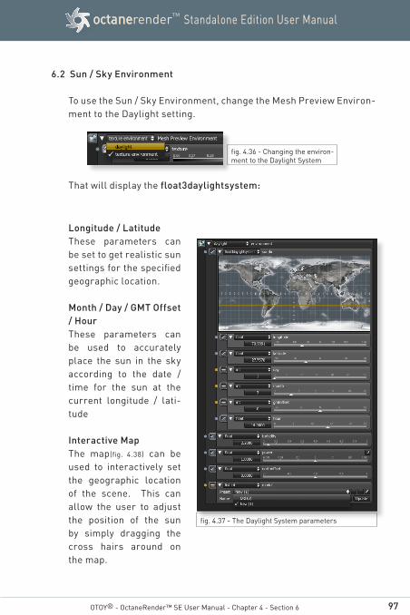
97
Standalone Edition User ManualoctanerenderTM
OTOY® - OctaneRender™ SE User Manual - Chapter 4 - Section 6
6.2 Sun / Sky Environment
To use the Sun / Sky Environment, change the Mesh Preview Environ-ment to the Daylight setting.
fig. 4.36 - Changing the environ-ment to the Daylight System
fig. 4.37 - The Daylight System parameters
That will display the float3daylightsystem:
Longitude / LatitudeThese parameters can be set to get realistic sun settings for the specified geographic location.
Month / Day / GMT Offset / HourThese parameters can be used to accurately place the sun in the sky according to the date / time for the sun at the current longitude / lati-tude
Interactive MapThe map(fig. 4.38) can be used to interactively set the geographic location of the scene. This can allow the user to adjust the position of the sun by simply dragging the cross hairs around on the map.

98
Standalone Edition User ManualoctanerenderTM
OTOY® - OctaneRender™ SE User Manual - Chapter 4 - Section 6
TurbidityThe Turbidity can be used to adjust the sharpness of the sun lights shadows. A low value creates sharp shadows (like on a sunny day) and a higher value diffuses the shadows similarly to a cloudy day.
PowerThe Power slider can be used to adjust the strength of the light. This can affect overall contrast and exposure level of the image.
North OffsetThe North offset slider can be used to adjust the actual North direc-tion of the scene. This is useful for Architecture Visualization to en-sure the direction of the sun is accurate to the scene.
ModelThis specifies which daylight model to be used as the current envi-ronment. The old daylight model lights a scene with spectral radi-ance assuming that the sun is moving over the horizon at a constant distance from the object. The new daylight model is used to simulate full spectrum daylight with the sun hovering at a varying distance from the tangent plane providing more sky color variation as the sun moves along and then bears shorter rays as the sun moves closer to the normal plane.
fig. 4.38 - The Interactive Map can be used to set the location of the scene for accurate lighting

99
Standalone Edition User ManualoctanerenderTM
OTOY® - OctaneRender™ SE User Manual - Chapter 4 - Section 6
6.3 Mesh Emitters
Mesh Emitters allow an object to be used as a light source. This can be used with both Texture and Sun / Sky lighting systems.
In order to use a mesh as a light source, it needs to be changed to a Diffuse material type. The Emission parameter has three different options:
Null Emission - This sets the diffuse material as a standard diffuse material with no light emission.
Blackbody - The Blackbody Emis-sion type uses Colour Temperature (in Kel-vin) and Power to con-trol the colour and in-tensity of the light.
Texture Emission - This allows any valid texture type to set the light intensity. This can be used to create neat effects such as TV screens by using an Image Texture as the source.
Light source sampling rates - in earlier versions of OctaneRender™ light sources were sampled according to area. In some scenes this will lead to a poor balance between light sources. In a room with a big TV (which emits some light) and a couple of small bright spotlights, the TV would have been sampled most of the time, leading to a lot of noise in the light from the spotlights.
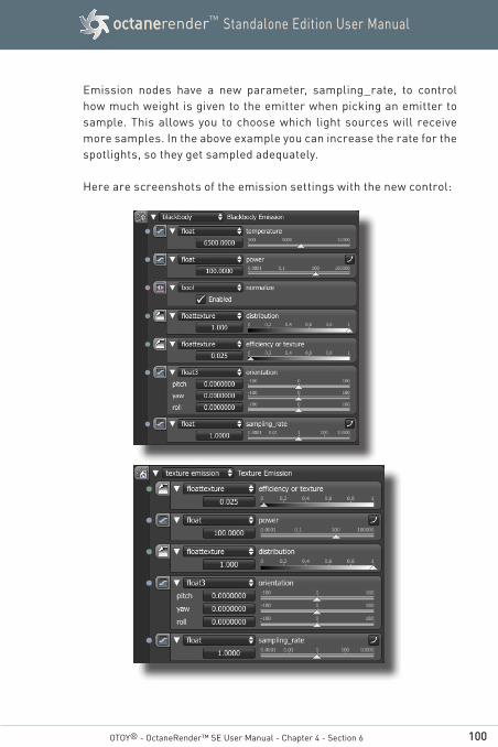
100
Standalone Edition User ManualoctanerenderTM
OTOY® - OctaneRender™ SE User Manual - Chapter 4 - Section 6
Emission nodes have a new parameter, sampling_rate, to control how much weight is given to the emitter when picking an emitter to sample. This allows you to choose which light sources will receive more samples. In the above example you can increase the rate for the spotlights, so they get sampled adequately.
Here are screenshots of the emission settings with the new control:
101
Standalone Edition User ManualoctanerenderTM
OTOY® - OctaneRender™ SE User Manual - Chapter 4 - Section 6.3
The following settings are listed for the Blackbody emission set-tings, but many of the settings are shared with the Texture emission settings. The main difference is whether the colour comes from the Blackbody temperature or from the texture settings of the diffuse material.
Temperature - The temperature (in K) of the light emission.
Power - This is the wattage of the light source. Each light in the scene should be set to its real world wattage. For example, a desk lamp could be set to 25 watts, a ceiling lamp to 100 watts, and an LED light to 0.25 watts. This setting should not be used to balance the lighting power of the scene.
Efficiency or Texture - This setting is used to set the efficiency of the light source. No light is 100% efficient at delivering the power at the specified wattage (a 100 watt light bulb does not actually deliver 100 watts of light.) The efficiency setting can be used to enter the real-world values.
These values can be used to create very realistic light settings. For example, a standard 100 watt incandescent bulb would only be ap-proximately 2.0% efficient where as a 25 watt compact fluorescent light will be 10% efficient. These will both produce around the same quantity of light in real life.
Orientation - This setting is used to adjust the direction the light is pointed in the scene. This setting only affects lights using a non-uniform distribution (textures or IES files).
Distribution - The distribution controls the pattern of the light. This can be set to a floattexture and an image or IES file can be loaded.
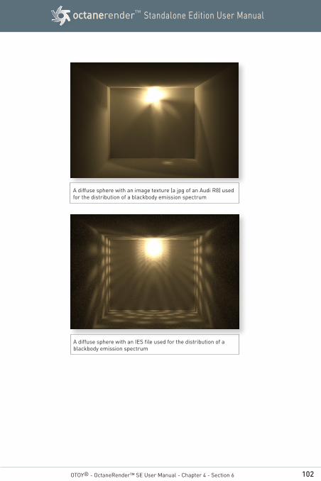
102
Standalone Edition User ManualoctanerenderTM
OTOY® - OctaneRender™ SE User Manual - Chapter 4 - Section 6
A diffuse sphere with an image texture (a jpg of an Audi R8) used for the distribution of a blackbody emission spectrum
A diffuse sphere with an IES file used for the distribution of a blackbody emission spectrum
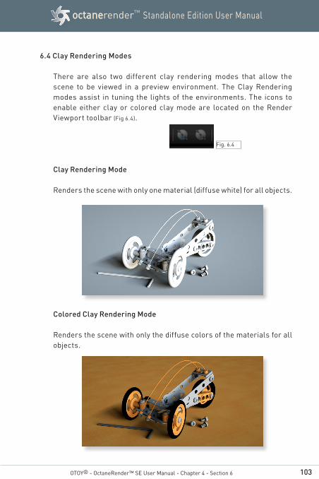
103
Standalone Edition User ManualoctanerenderTM
6.4 Clay Rendering Modes
There are also two different clay rendering modes that allow the scene to be viewed in a preview environment. The Clay Rendering modes assist in tuning the lights of the environments. The icons to enable either clay or colored clay mode are located on the Render Viewport toolbar (Fig 6.4).
Clay Rendering Mode
Renders the scene with only one material (diffuse white) for all objects.
Colored Clay Rendering Mode
Renders the scene with only the diffuse colors of the materials for all objects.
OTOY® - OctaneRender™ SE User Manual - Chapter 4 - Section 6
Fig. 6.4

104
Standalone Edition User ManualoctanerenderTM
6.5 Using Portals
Portals are a technique to help the render kernel find important light sources. In interior renderings with windows, it is difficult for the path tracer to find light from the outside environment and optimally render the scene. Portals are planes that are added to the scene in the host modeling program that are used by OctaneRender™ to more efficiently render the scene.
In the image to the right, a room is being prepared with a small, sin-gle window. This would be a difficult scene to light with a sun/sky or HDRI file with no lighting on the interior of the room.
A single plane was placed over the window (orange) with the normal for the plane facing into the room (blue line).
OTOY® - OctaneRender™ SE User Manual - Chapter 4 - Section 6

105
Standalone Edition User ManualoctanerenderTM
Portal Usage Notes:
When using Portals, all opening must be covered with a portal. It will not work if only one window has a portal over it when all other win-dows do not have a portal over them. The normals on the Portal object MUST be pointed into the scene or the render kernel will not use it properly.
Currently, portals cannot be placed in openings which are not open, eg a window with a portal cannot contain glass at this time.
In some complex scenes and situations, portals might slow down the render, so a bit of experimentation with/without should be done.
Portals only apply to pathtracing type kernels, eg pathtracing and PMC. (not directlighting/ambient occlusion)
It is best to try to use the least amount of geometry for portals, eg only a few simple rectangular planes are best, the more geometry your portals contain, the slower the engine might become.
Sometimes it is better to place one large portal over many small win-dows due to the above. It's ok to make a portal larger than the open-ing, just make sure it closes/covers all opening(s). A portal which is unnecessarily large will end up slowing down the efficiency, as some of the rays through the covered parts of the portal will not go outside the space.
Portals, when defined with the portal material, will not show up in your render, eg this will be invisible geometry.
OTOY® - OctaneRender™ SE User Manual - Chapter 4 - Section 6
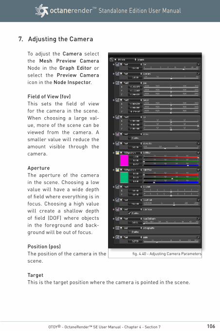
106
Standalone Edition User ManualoctanerenderTM
OTOY® - OctaneRender™ SE User Manual - Chapter 4 - Section 7
7. Adjusting the Camera
To adjust the Camera select the Mesh Preview Camera Node in the Graph Editor or select the Preview Camera icon in the Node Inspector.
Field of View (fov)This sets the field of view for the camera in the scene. When choosing a large val-ue, more of the scene can be viewed from the camera. A smaller value will reduce the amount visible through the camera.
ApertureThe aperture of the camera in the scene. Choosing a low value will have a wide depth of field where everything is in focus. Choosing a high value will create a shallow depth of field (DOF) where objects in the foreground and back-ground will be out of focus.
Position (pos)The position of the camera in thescene.
TargetThis is the target position where the camera is pointed in the scene.
fig. 4.40 - Adjusting Camera Parameters
107
Standalone Edition User ManualoctanerenderTM
UpThis is the up direction of the camera in the scene. By default this is in the Y-direction (0,1,0).
StereoThis enables whether anaglyphic stereo rendering is active. When active, the render will be able to be viewed with Red / Blue 3D glasses
LeftFilter / RightFilterThe left and right filter colors are used to adjust the colors used to create the anaglyphic stereo affect in the render.
Lens ShiftThis is useful for architectural rendering, when you want to render im-ages of tall buildings/structures from a similar height as the human eye, but keeping the vertical lines parallel
Near Clip Depth The main purpose was for interior scenes where you want to get a good shot of the whole room but you cannot do so without a very large FOV, because you need to keep the camera inside the room.
With camera clipping (near plane), you can position the camera outside the room - lower the FOV and increase the clipping plane distance in front of you until the closest walls are clipped out. The geometry is not altered, only the clipping of the camera, which means that shadows, reflections and refractions are still affected by the clipped geometry
Orthographic This enables or disables Orthographic Camera mode. When active, all same-length parallel edges display as the same length regardless of the perspective that should result from the object's orientation.
ScaleThis sets the viewing width, in meters, when in orthographic camera mode. The scale is linked to the FOV parameter.
OTOY® - OctaneRender™ SE User Manual - Chapter 4 - Section 8
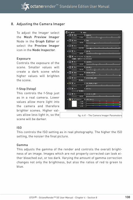
108
Standalone Edition User ManualoctanerenderTM
8. Adjusting the Camera Imager
To adjust the Imager select the Mesh Preview Imager Node in the Graph Editor or select the Preview Imager icon in the Node Inspector.
ExposureControls the exposure of the scene. Smaller values will create a dark scene while higher values will brighten the scene.
f-Stop (fstop)This controls the f-Stop just as in a real camera. Lower values allow more light into the camera and therefore brighter scenes. Higher val-ues allow less light in, so the scene will be darker.
ISOThis controls the ISO setting as in real photography. The higher the ISO setting, the noisier the final picture.
GammaThis adjusts the gamma of the render and controls the overall bright-ness of an image. Images which are not properly corrected can look ei-ther bleached out, or too dark. Varying the amount of gamma correction changes not only the brightness, but also the ratios of red to green to blue.
OTOY® - OctaneRender™ SE User Manual - Chapter 4 - Section 8
fig. 4.41 - The Camera Imager Parameters
109
Standalone Edition User ManualoctanerenderTM
ResponseThe use of measured camera response curves can be selected. Please see Appendix 2 for examples of all the settings. VignettingAdjusting this parameter increases the amount of darkening in the cor-ners of the render. Used sparingly, it can greatly increase the realism of the render.
SaturationAdjusts the amount of color saturation of the render
Hot Pixel RemovalThe Hot Pixel Removal slider is used to remove the bright pixels (fireflies) during the rendering process. While many of the pixels can dissappear if the render is allowed to progress, the Hot Pixel Removal feature allows the bright pixels to be removed at a much lower Sample per Pixel.
Pre-multiplied AlphaChecking the Pre-multiplied Alpha button multiplies any transparency value of the output pixel by the pixels color.
Min Display Samples This is minimum amount of samples that is calculated before the image is displayed. This feature can significantly reduce the noise when navigat-ing and is useful for real-time walkthroughs. When using multiple GPUs, it's recommended to set this value as a multiple of the number of avail-able GPUs for rendering, e.g. if you're rendering with 4 GPUs, set this value at 4 or 8.
Dithering Adds random noise which removes banding in very clean images.
sRGB Colour Picker Space
To invoke the sRGB Colour Picker Space, click on the coloured square found in the diffuse sliders in the Node Inspector to show a panel of colours that allows easier color picking.
OTOY® - OctaneRender™ SE User Manual - Chapter 4 - Section 8
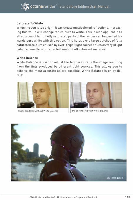
110
Standalone Edition User ManualoctanerenderTM
Saturate To White When the sun is too bright, it can create multicolored reflections. Increas-ing this value will change the colours to white. This is also applicable to all sources of light. Fully saturated parts of the render can be pushed to-wards pure white with this option. This helps avoid large patches of fully saturated colours caused by over-bright light sources such as very bright coloured emitters or reflected sunlight off coloured surfaces. White Balance White Balance is used to adjust the temperature in the image resulting from the tints produced by different light sources. This allows you to acheive the most accurate colors possible. White Balance is on by de-fault.
Image rendered without White Balance Image rendered with White Balance
By Icelaglace
OTOY® - OctaneRender™ SE User Manual - Chapter 4 - Section 8
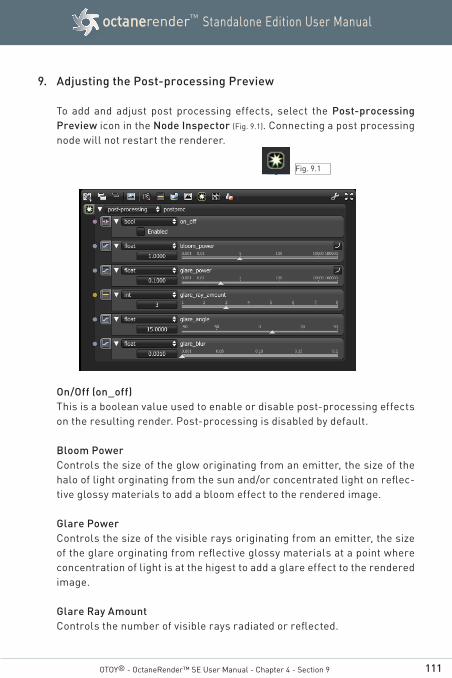
111
Standalone Edition User ManualoctanerenderTM
OTOY® - OctaneRender™ SE User Manual - Chapter 4 - Section 9
9. Adjusting the Post-processing Preview
To add and adjust post processing effects, select the Post-processing Preview icon in the Node Inspector (Fig. 9.1). Connecting a post processing node will not restart the renderer.
On/Off (on_off)This is a boolean value used to enable or disable post-processing effects on the resulting render. Post-processing is disabled by default.
Bloom PowerControls the size of the glow originating from an emitter, the size of the halo of light orginating from the sun and/or concentrated light on reflec-tive glossy materials to add a bloom effect to the rendered image.
Glare PowerControls the size of the visible rays originating from an emitter, the size of the glare orginating from reflective glossy materials at a point where concentration of light is at the higest to add a glare effect to the rendered image.
Glare Ray AmountControls the number of visible rays radiated or reflected.
Fig. 9.1
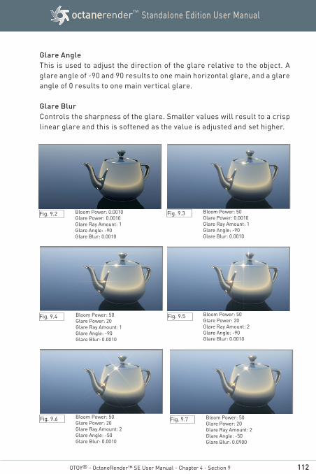
112
Standalone Edition User ManualoctanerenderTM
OTOY® - OctaneRender™ SE User Manual - Chapter 4 - Section 9
Glare AngleThis is used to adjust the direction of the glare relative to the object. A glare angle of -90 and 90 results to one main horizontal glare, and a glare angle of 0 results to one main vertical glare.
Glare BlurControls the sharpness of the glare. Smaller values will result to a crisp linear glare and this is softened as the value is adjusted and set higher.
Bloom Power: 0.0010Glare Power: 0.0010Glare Ray Amount: 1Glare Angle: -90Glare Blur: 0.0010
Bloom Power: 50Glare Power: 0.0010Glare Ray Amount: 1Glare Angle: -90Glare Blur: 0.0010
Bloom Power: 50Glare Power: 20Glare Ray Amount: 1Glare Angle: -90Glare Blur: 0.0010
Bloom Power: 50Glare Power: 20Glare Ray Amount: 2Glare Angle: -90Glare Blur: 0.0010
Bloom Power: 50Glare Power: 20Glare Ray Amount: 2Glare Angle: -50Glare Blur: 0.0010
Bloom Power: 50Glare Power: 20Glare Ray Amount: 2Glare Angle: -50Glare Blur: 0.0900
Fig. 9.2 Fig. 9.3
Fig. 9.4 Fig. 9.5
Fig. 9.6 Fig. 9.7

113
Standalone Edition User ManualoctanerenderTM
(Sun glare)
(Bloom effect)
(Bloom and Glare on a ring)
OTOY® - OctaneRender™ SE User Manual - Chapter 4 - Section 9
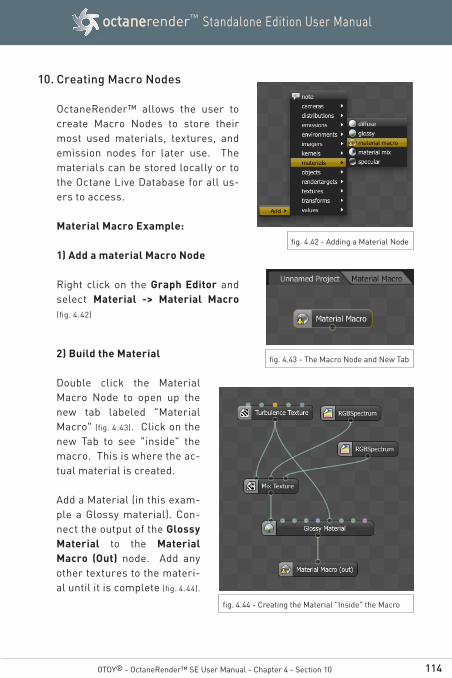
114
Standalone Edition User ManualoctanerenderTM
10. Creating Macro Nodes
OctaneRender™ allows the user to create Macro Nodes to store their most used materials, textures, and emission nodes for later use. The materials can be stored locally or to the Octane Live Database for all us-ers to access.
Material Macro Example:
1) Add a material Macro Node
Right click on the Graph Editor and select Material -> Material Macro (fig. 4.42)
OTOY® - OctaneRender™ SE User Manual - Chapter 4 - Section 10
fig. 4.43 - The Macro Node and New Tab
fig. 4.44 - Creating the Material "Inside" the Macro
2) Build the Material
Double click the Material Macro Node to open up the new tab labeled "Material Macro" (fig. 4.43). Click on the new Tab to see "inside" the macro. This is where the ac-tual material is created.
Add a Material (in this exam-ple a Glossy material). Con-nect the output of the Glossy Material to the Material Macro (Out) node. Add any other textures to the materi-al until it is complete (fig. 4.44).
fig. 4.42 - Adding a Material Node
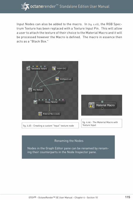
115
Standalone Edition User ManualoctanerenderTM
Input Nodes can also be added to the macro. In (fig. 4.45), the RGB Spec-trum Texture has been replaced with a Texture Input Pin. This will allow a user to attach the texture of their choice to the Material Macro and it will be processed however the Macro is defined. The macro in essence then acts as a "Black Box."
OTOY® - OctaneRender™ SE User Manual - Chapter 4 - Section 10
fig. 4.45 - Creating a custom "Input" texture nodefig. 4.46 - The Material Macro with Texture Input
Renaming the Nodes
Nodes in the Graph Editor pane can be renamed by renam-ing their counterparts in the Node Inspector pane.
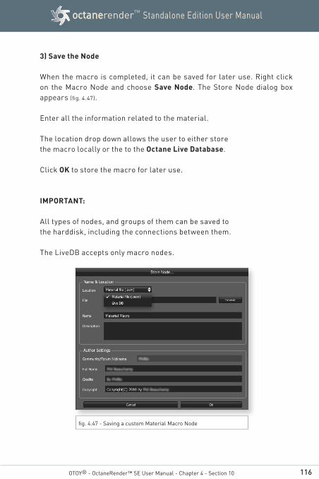
116
Standalone Edition User ManualoctanerenderTM
3) Save the Node
When the macro is completed, it can be saved for later use. Right click on the Macro Node and choose Save Node. The Store Node dialog box appears (fig. 4.47).
Enter all the information related to the material.
The location drop down allows the user to either storethe macro locally or the to the Octane Live Database.
Click OK to store the macro for later use.
IMPORTANT:
All types of nodes, and groups of them can be saved tothe harddisk, including the connections between them.
The LiveDB accepts only macro nodes.
OTOY® - OctaneRender™ SE User Manual - Chapter 4 - Section 10
fig. 4.47 - Saving a custom Material Macro Node
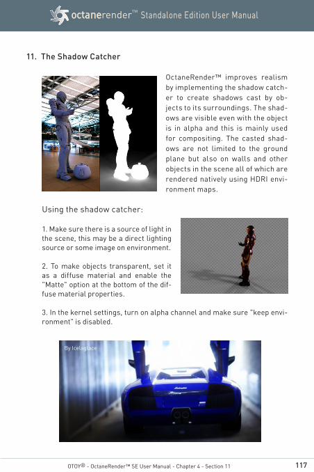
117
Standalone Edition User ManualoctanerenderTM
OTOY® - OctaneRender™ SE User Manual - Chapter 4 - Section 11
11. The Shadow Catcher
OctaneRender™ improves realism by implementing the shadow catch-er to create shadows cast by ob-jects to its surroundings. The shad-ows are visible even with the object is in alpha and this is mainly used for compositing. The casted shad-ows are not limited to the ground plane but also on walls and other objects in the scene all of which are rendered natively using HDRI envi-ronment maps.
Using the shadow catcher:
1. Make sure there is a source of light in the scene, this may be a direct lighting source or some image on environment.
2. To make objects transparent, set it as a diffuse material and enable the "Matte" option at the bottom of the dif-fuse material properties.
3. In the kernel settings, turn on alpha channel and make sure "keep envi-ronment" is disabled.
By Icelaglace
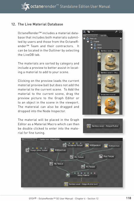
118
Standalone Edition User ManualoctanerenderTM
OTOY® - OctaneRender™ SE User Manual - Chapter 4 - Section 12
12. The Live Material Database
OctaneRender™ includes a material data-base that includes both materials submit-ted by users and those from the OctaneR-ender™ Team and their contractors. It can be located in the Outliner by selecting the LiveDB tab.
The materials are sorted by category and include a preview to better assist in locat-ing a material to add to your scene.
Clicking on the preview loads the current material preview ball but does not add the material to the current scene. To Add the material to the current scene, drag the preview picture to the Graph Editor or to an object in the scene in the viewport. The matereial can also be dragged and dropped into the Node Inspector.
The material will be placed in the Graph Editor as a Material Macro which can then be double clicked to enter into the mate-rial for fine tuning.
119
Standalone Edition User ManualoctanerenderTM
Chapter 5
Saving and Loading Scenes in
OctaneRender™
OTOY® - OctaneRender™ SE User Manual
Elvissuperstar007
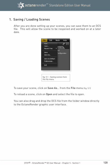
120
Standalone Edition User ManualoctanerenderTM
OTOY® - OctaneRender™ SE User Manual - Chapter 5 - Section 1
1. Saving / Loading Scenes
After you are done setting up your scenes, you can save them to an OCS file. This will allow the scene to be reopened and worked on at a later date.
To save your scene, click on Save As… from the File menu (fig. 5.1)
To reload a scene, click on Open and select the file to open.
You can also drag and drop the OCS file from the folder window directly to the OctaneRender graphic user interface.
fig. 5.1 - Saving scenes from the file menu
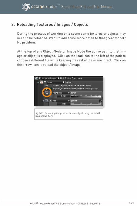
121
Standalone Edition User ManualoctanerenderTM
OTOY® - OctaneRender™ SE User Manual - Chapter 5 - Section 2
2. Reloading Textures / Images / Objects
During the process of working on a scene some textures or objects may need to be reloaded. Want to add some more detail to that great model? No problem.
At the top of any Object Node or Image Node the active path to that im-age or object is displayed. Click on the load icon to the left of the path to choose a different file while keeping the rest of the scene intact. Click on the arrow icon to reload the object / image.
fig. 5.2 - Reloading images can be done by clicking the small icon shown here

122
Standalone Edition User ManualoctanerenderTM
Chapter 6
Geometry
OTOY® - OctaneRender™ SE User Manual
Stanford dragon textured by face
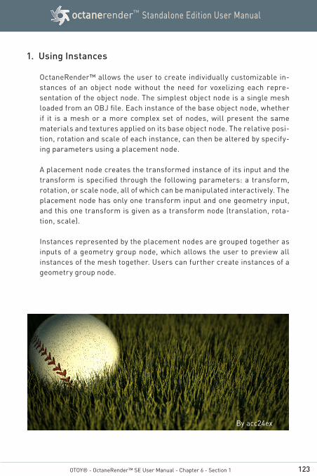
123
Standalone Edition User ManualoctanerenderTM
1. Using Instances
OctaneRender™ allows the user to create individually customizable in-stances of an object node without the need for voxelizing each repre-sentation of the object node. The simplest object node is a single mesh loaded from an OBJ file. Each instance of the base object node, whether if it is a mesh or a more complex set of nodes, will present the same materials and textures applied on its base object node. The relative posi-tion, rotation and scale of each instance, can then be altered by specify-ing parameters using a placement node.
A placement node creates the transformed instance of its input and the transform is specified through the following parameters: a transform, rotation, or scale node, all of which can be manipulated interactively. The placement node has only one transform input and one geometry input, and this one transform is given as a transform node (translation, rota-tion, scale).
Instances represented by the placement nodes are grouped together as inputs of a geometry group node, which allows the user to preview all instances of the mesh together. Users can further create instances of a geometry group node.
OTOY® - OctaneRender™ SE User Manual - Chapter 6 - Section 1
By acc24ex
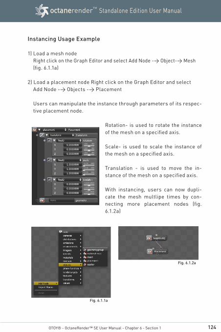
124
Standalone Edition User ManualoctanerenderTM
Instancing Usage Example
1) Load a mesh nodeRight click on the Graph Editor and select Add Node -> Object-> Mesh (fig. 6.1.1a)
2) Load a placement node Right click on the Graph Editor and select Add Node -> Objects -> Placement
Users can manipulate the instance through parameters of its respec-tive placement node.
Rotation- is used to rotate the instance of the mesh on a specified axis.
Scale- is used to scale the instance of the mesh on a specified axis.
Translation - is used to move the in-stance of the mesh on a specified axis.
With instancing, users can now dupli-cate the mesh multlipe times by con-necting more placement nodes (fig. 6.1.2a)
OTOY® - OctaneRender™ SE User Manual - Chapter 6 - Section 1
Fig. 6.1.1a
Fig. 6.1.2a
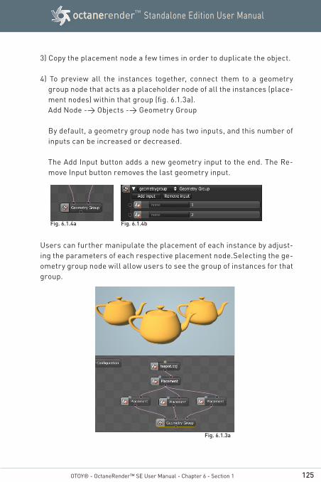
125
Standalone Edition User ManualoctanerenderTM
3) Copy the placement node a few times in order to duplicate the object.
4) To preview all the instances together, connect them to a geometry group node that acts as a placeholder node of all the instances (place-ment nodes) within that group (fig. 6.1.3a).Add Node -> Objects -> Geometry Group
By default, a geometry group node has two inputs, and this number of inputs can be increased or decreased.
The Add Input button adds a new geometry input to the end. The Re-move Input button removes the last geometry input.
Users can further manipulate the placement of each instance by adjust-ing the parameters of each respective placement node.Selecting the ge-ometry group node will allow users to see the group of instances for that group.
OTOY® - OctaneRender™ SE User Manual - Chapter 6 - Section 1
Fig. 6.1.4a Fig. 6.1.4b
Fig. 6.1.3a

126
Standalone Edition User ManualoctanerenderTM
The are many possibilities of using these object nodes to implement in-stancing. For example, users can create instances of the same geom-etery group by selecting an entire group of nodes including its dependent placement nodes and copy-pasting them into the graph editor.
The geometry groups or its placement nodes can be connected and nested further as inputs of a new geometry group. Selecting the new geometry group node will allow users to preview all instances within the collection of nodes.
OTOY® - OctaneRender™ SE User Manual - Chapter 6 - Section 1
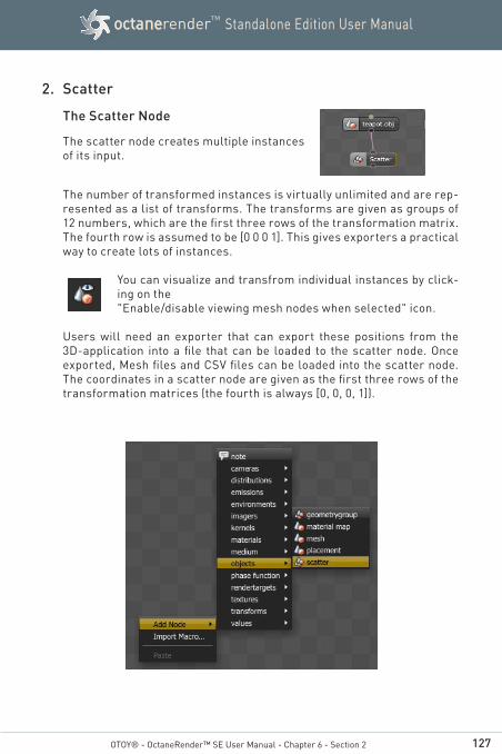
127
Standalone Edition User ManualoctanerenderTM
2. Scatter
The Scatter Node
The scatter node creates multiple instances of its input.
The number of transformed instances is virtually unlimited and are rep-resented as a list of transforms. The transforms are given as groups of 12 numbers, which are the first three rows of the transformation matrix. The fourth row is assumed to be [0 0 0 1]. This gives exporters a practical way to create lots of instances.
You can visualize and transfrom individual instances by click-ing on the "Enable/disable viewing mesh nodes when selected" icon.
Users will need an exporter that can export these positions from the 3D-application into a file that can be loaded to the scatter node. Once exported, Mesh files and CSV files can be loaded into the scatter node. The coordinates in a scatter node are given as the first three rows of the transformation matrices (the fourth is always [0, 0, 0, 1]).
OTOY® - OctaneRender™ SE User Manual - Chapter 6 - Section 2

128
Standalone Edition User ManualoctanerenderTM
OTOY® - OctaneRender™ SE User Manual - Chapter 6 - Section 2
For example the matrix for a 30° rotation around the Z axis looks like this:
[.87, –.50, 0, 0][.50, .87, 0, 0][ 0, 0, 1, 0][ 0, 0, 0, 1]
The scatter node will contain these 12 values:.87 –.50 0 0 .50 .87 0 0 0 0 1 0
For a translation:
[1, 0, 0, tx][0, 1, 0, ty][0, 0, 1, tz][0, 0, 0, 1]
The scatter node will contain these 12 values:1 0 0 tx 0 1 0 ty 0 0 1 tz
These values have to be exported from modeling applications and then loaded unto a scatter node.
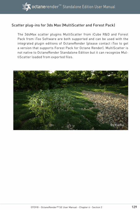
129
Standalone Edition User ManualoctanerenderTM
By Karba
OTOY® - OctaneRender™ SE User Manual - Chapter 6 - Section 2
Scatter plug-ins for 3ds Max (MultiScatter and Forest Pack)
The 3dsMax scatter plugins MultiScatter from iCube R&D and Forest Pack from iToo Software are both supported and can be used with the integrated plugin editions of OctaneRender (please contact iToo to get a version that supports Forest Pack for Octane Render). MultiScatter is not native to OctaneRender Standalone Edition but it can recognize Mul-tiScatter loaded from exported files.
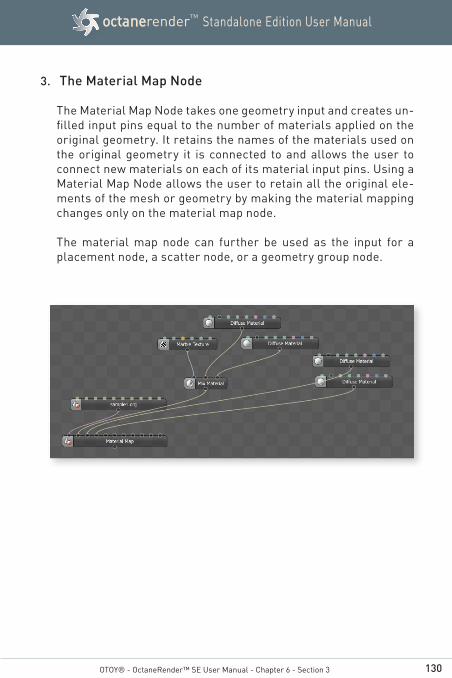
130
Standalone Edition User ManualoctanerenderTM
3. The Material Map Node
The Material Map Node takes one geometry input and creates un-filled input pins equal to the number of materials applied on the original geometry. It retains the names of the materials used on the original geometry it is connected to and allows the user to connect new materials on each of its material input pins. Using a Material Map Node allows the user to retain all the original ele-ments of the mesh or geometry by making the material mapping changes only on the material map node.
The material map node can further be used as the input for a placement node, a scatter node, or a geometry group node.
OTOY® - OctaneRender™ SE User Manual - Chapter 6 - Section 3

131
Standalone Edition User ManualoctanerenderTM
Appendix I
Advanced Topics
by CoCo
132
Standalone Edition User ManualoctanerenderTM
1. Launching Octane from the Command Line
OctaneRender™ supports passing command line parameters to utilize scripting or other automated tasks.
The following is an example of the workflow for working with OctaneRen-der™ from the Command Line.
To utilize the command line options, you must do the following:
1. Save the scene to an OCS file. You must know the full path to this scene.
Example: C:\Temp\OctaneTest.ocs
2. Remember the name of the mesh node that you want to render. This typically is the node for the imported OBJ. Example “OctaneTest.obj”
3. If the scene geometry has changed and needs to be reloaded, note the full path Example: C:\Temp\NewGeom.obj
4. Octane can then be launched from the command line using the fol-lowing syntax
By lechu

133
Standalone Edition User ManualoctanerenderTM
USAGE :
octane [-m <string>] [-r <filename>] [-l<filename>] [-n<filename>] [--imager-exposure <float>]
[--daylight-sundir-z <float>] [--daylight-sundir-y <float>] [--daylight-sundir-x <float>]
[--cam-aperture <float>] [--cam-focaldepth <float>]
[--cam-fov <float>] [--cam-motion-up-z <float>]
--cam-motion-up-y <float>] [--cam-motion-up-x<float>] [--cam-motion-target-z <float>]
[--cam-motion-target-y <float>]
[--cam-motion-target-x <float>] [--cam-motion-pos-z<float>] [--cam-motion-pos-y <float>]
[--cam-motion-pos-x <float>] [--cam-up-z <float>]
[--cam-up-y <float>] [--cam-up-x <float>]
[--cam-target-z <float>] [--cam-target-y <float>]
[--cam-target-x <float>] [--cam-pos-z <float>]
[--cam-pos-y <float>] [--cam-pos-x <float>] [-q] [-g<int>] ... [-s <int>] [-o <filename>]
[--film-height <int>] [--film-width <int>] [-e] [--]
[--version] [-h] <filename>
WHERE :
-t <node name>, --target-node <node name> Name of the render target node to render
-m <string>, --mesh-node <string>Name of meshnode to render
-r <filename>, --relink-meshnode <filename>Name of OBJ mesh file to relink rendered meshnoded with
-l <filename>, --link-meshnode <filename>Name of OBJ mesh file to link after startup
-n <filename>, --new <filename>Create a new OCS project file from given command line arguments
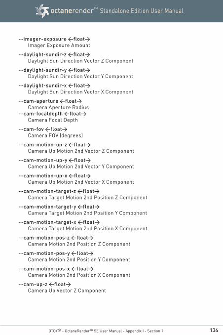
134
Standalone Edition User ManualoctanerenderTM
OTOY® - OctaneRender™ SE User Manual - Appendix I - Section 1
--imager-exposure <float>Imager Exposure Amount
--daylight-sundir-z <float>Daylight Sun Direction Vector Z Component
--daylight-sundir-y <float>Daylight Sun Direction Vector Y Component
--daylight-sundir-x <float>Daylight Sun Direction Vector X Component
--cam-aperture <float>Camera Aperture Radius
--cam-focaldepth <float>Camera Focal Depth
--cam-fov <float>Camera FOV (degrees)
--cam-motion-up-z <float>Camera Up Motion 2nd Vector Z Component
--cam-motion-up-y <float>Camera Up Motion 2nd Vector Y Component
--cam-motion-up-x <float>Camera Up Motion 2nd Vector X Component
--cam-motion-target-z <float>Camera Target Motion 2nd Position Z Component
--cam-motion-target-y <float>Camera Target Motion 2nd Position Y Component
--cam-motion-target-x <float>Camera Target Motion 2nd Position X Component
--cam-motion-pos-z <float>Camera Motion 2nd Position Z Component
--cam-motion-pos-y <float>Camera Motion 2nd Position Y Component
--cam-motion-pos-x <float>Camera Motion 2nd Position X Component
--cam-up-z <float>Camera Up Vector Z Component
135
Standalone Edition User ManualoctanerenderTM
OTOY® - OctaneRender™ SE User Manual - Appendix I - Section 1
--cam-up-y <float>Camera Up Vector Y Component
--cam-up-x <float>Camera Up Vector X Component
--cam-target-z <float>Camera Target Position Z Component
--cam-target-y <float>Camera Target Position Y Component
--cam-target-x <float>Camera Target Position X Component
--cam-pos-z <float>Camera Position Z Component
--cam-pos-y <float>Camera Position Y Component
--cam-pos-x <float>Camera Position X Component
-q, --quietStart Application without splash and minimized window
-g <int>, --gpu <int> (accepted multiple times)add GPU device to use for rendering (0 = first)
-s <int>, --samples <int>Maximum number of samples per pixel (maxsamples)
-o <filename>, --output-png <filename>Output PNG imagefile when maxsamples is reached
--film-height <int>Film height
--film-width <int>Film width
-e, --exitClose the application when rendering is done
--, --ignore_restIgnores the rest of the labeled arguments following this flag.
--versionDisplays version information and exits.

136
Standalone Edition User ManualoctanerenderTM
OTOY® - OctaneRender™ SE User Manual - Appendix I - Section 1
Why are there two sets of Camera Parameters?
The second camera control (-- cam-motion) is used to specify the cam-era position in the next frame. OctaneRender™ will then use the cur-rent position and the next frame position to calculate motion blur be-tween the two camera positions.
-h, --helpDisplays usage information and exits.
<filename>.OCS Project scene file
For example, to open a file (C:\Temp\OctaneTest.ocs), relink the geometry (C:\Temp\NewGeometry.obj), select the meshnode (OctaneTest.obj) and ren-der the frame for 1000 samples per pixel, save the render and exit:
octane –e –r C:\Temp\NewGeometry.obj –m OctaneTest.obj –s 1000 –o C:\temp\test.png C:\Temp\OctaneTest.ocs
Other examples:
$ octane "OctaneBenchmark/octane_benchmark for 1022 beta 2.2rc.ocs"$ octane "some test scene.ocs"
137
Standalone Edition User ManualoctanerenderTM
OTOY® - OctaneRender™ SE User Manual - Appendix I - Section 2
2. One-Click Turn-Table Animations
OctaneRender™ supports the ability to perform turntable animations with a single click of a button. This doesn’t require any knowledge of programming camera paths or any other advanced knowledge.
1. Position the camera so that the object or scene is centered properly in the viewport
2. Set the center of rotation by using the Focus Picker and clicking on the center of the object (or by setting the center of rotation by setting the Camera Target X,Y, and Z values manually)
3. Open the Turn Table Animation Setting Window by clicking on the icon:
fig. I.1 - The Turntable Animation Settings Dialog
4. Adjust the settings as required to get the desired motion, length and quality.

138
Standalone Edition User ManualoctanerenderTM
OTOY® - OctaneRender™ SE User Manual - Appendix I - Section 2
How do I create an animation from the Image sequence?
To convert the images into an animation requires the use of a second program. Both Virtualdub and Blender can be used to complete this task.
5. Set the Image Output by clicking on the Set button. Select a folder where the resulting images will be stored and type a file prefix. All the images in the animation will then be stored in that directory with a number sequence after the entered file prefix.
6. Click the Render Button to create the image sequence.
3. One-Click Sun / Sky Animations
OctaneRender™ supports the ability to perform sun/sky animations with a single click of a button. This doesn’t require any knowledge of program-ming light paths or any other advanced knowledge. This creates an easy way to make impressive architectural visualization animations.
1. Adjust the scene and position of the camera
2. Set the Preview Environment type to Daylight
3. Set the sun position (via the map or longitude / latitude)
4. Preview the motion of the sun by sliding the Hour slider. Continue to tweak the position of the sun and the North Offset until adjusting the Hour slider produces the desired sun path.
5) Click on the Daylight Simulation Animation icon.
6) Adjust the Daylight, output and quality settings.
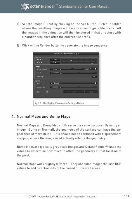
139
Standalone Edition User ManualoctanerenderTM
7) Set the Image Output by clicking on the Set button. Select a folder where the resulting images will be stored and type a file prefix. All the images in the animation will then be stored in that directory with a number sequence after the entered file prefix.
8) Click on the Render button to generate the image sequence.
OTOY® - OctaneRender™ SE User Manual - Appendix I - Section 3
fig. I.2 - The Daylight Simulation Settings Dialog
4. Normal Maps and Bump Maps
Normal Maps and Bump Maps both serve the same purpose. By using an image (Bump or Normal), the geometry of the surface can have the ap-pearance of more detail. This should not be confused with displacement mapping where the image used actually affects the geometry.
Bump Maps are typically grey scale images and OctaneRender™ uses the values to determine how much to affect the geometry at that location of the pixel.
Normal Maps work slightly different. They are color images that use RGB values to add directionality to the raised or lowered areas.

140
Standalone Edition User ManualoctanerenderTM
OTOY® - OctaneRender™ SE User Manual - Appendix I - Section 4
Note: If both Normal Maps and Bump maps are used on the same mate-rial, the Normal Map will take a higher priority and be used and the Bump Map will be ignored.
In OctaneRender™, the normal map is interpreted in tangent space. The X-axis is the tangent vector in the dP/dU direction, the Y-axis is the other tangent vector and the Z-axis is the normal direction.
My Normal Maps from Z-Brush don’ t export properly. What can I do?
To get Z-Brush normal maps to work in OctaneRender™, you must enable the “Flip G” button under the Normal Map settings and the “Flip V” on the File Export
fig. I.3 - Z-Brush Normal Map Settings
fig. I.4 - Click on the "Flip V" button prior to export

141
Standalone Edition User ManualoctanerenderTM
Appendix II
Camera ResponseCurve Examples
OTOY® - OctaneRender™ SE User Manual
Credits : Scene modeled and rendered by Dave Girard
By Enrico Cerica
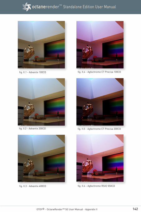
142
Standalone Edition User ManualoctanerenderTM
OTOY® - OctaneRender™ SE User Manual - Appendix II
fig. II.1 - Advantix 100CD
fig. II.2 - Advantix 200CD
fig. II.3 - Advantix 400CD
fig. II.4 - Agfachrome CT Precisa 100CD
fig. II.5 - Agfachrome CT Precisa 200CD
fig. II.6 - Agfachrome RSX2 050CD
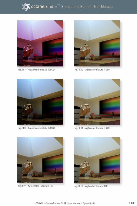
143
Standalone Edition User ManualoctanerenderTM
OTOY® - OctaneRender™ SE User Manual - Appendix II
fig. II.7 - Agfachrome RSX2 100CD
fig. II.8 - Agfachrome RSX2 200CD
fig. II.9 - Agfaccolor Futura II 100
fig. II.10 - Agfacolor Futura II 200
fig. II.11 - Agfacolor Futura II 400
fig. II.12 - Agfacolor Futura 100

144
Standalone Edition User ManualoctanerenderTM
OTOY® - OctaneRender™ SE User Manual - Appendix II
fig. II.13 - Agfacolor Futura 200
fig. II.14 - Agfacolor Futura 400
fig. II.15 - Agfacolor HDC 100
fig. II.16 - Agfacolor HDC 200
fig. II.17 - Agfacolor HDC 400
fig. II.18 - Agfacolor Optima II 100
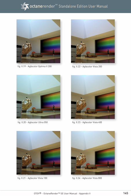
145
Standalone Edition User ManualoctanerenderTM
OTOY® - OctaneRender™ SE User Manual - Appendix II
fig. II.19 - Agfacolor Optima II 200
fig. II.20 - Agfacolor Ultra 050
fig. II.21 - Agfacolor Vista 100
fig. II.22 - Agfacolor Vista 200
fig. II.23 - Agfacolor Vista 400
fig. II.24 - Agfacolor Vista 800
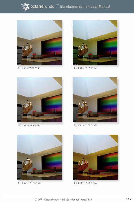
146
Standalone Edition User ManualoctanerenderTM
OTOY® - OctaneRender™ SE User Manual - Appendix II
fig. II.25 - DSCS 315 1
fig. II.26 - DSCS 315 2
fig. II.27 - DSCS 315 3
fig. II.28 - DSCS 315 4
fig. II.29 - DSCS 315 5
fig. II.30 - DSCS 315 6
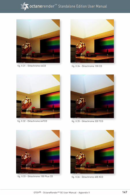
147
Standalone Edition User ManualoctanerenderTM
OTOY® - OctaneRender™ SE User Manual - Appendix II
fig. II.31 - Ektachrome 64CD
fig. II.32 - Ektachrome 64TCD
fig. II.33 - Ektachrome 100 Plus CD
fig. II.34 - Ektachrome 100 CD
fig. II.35 - Ektachrome 320 TCD
fig. II.36 - Ektachrome 400 XCD
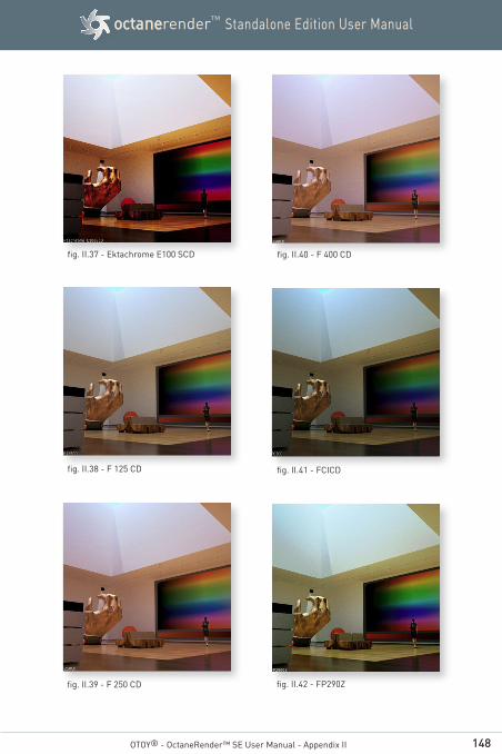
148
Standalone Edition User ManualoctanerenderTM
OTOY® - OctaneRender™ SE User Manual - Appendix II
fig. II.37 - Ektachrome E100 SCD
fig. II.38 - F 125 CD
fig. II.39 - F 250 CD
fig. II.40 - F 400 CD
fig. II.41 - FCICD
fig. II.42 - FP290Z
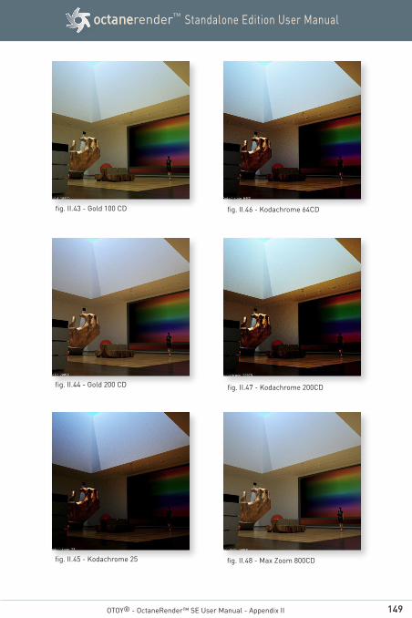
149
Standalone Edition User ManualoctanerenderTM
OTOY® - OctaneRender™ SE User Manual - Appendix II
fig. II.43 - Gold 100 CD
fig. II.44 - Gold 200 CD
fig. II.45 - Kodachrome 25
fig. II.46 - Kodachrome 64CD
fig. II.47 - Kodachrome 200CD
fig. II.48 - Max Zoom 800CD

150
Standalone Edition User ManualoctanerenderTM
OTOY® - OctaneRender™ SE User Manual - Appendix II
fig. II.49 - Porta 100TCD
fig. II.50 - Porta 160NCCD
fig. II.51 - Porta 160VCCD
fig. II.52 - Porta 400NCCD
fig. II.53 - Porta 400VCCD
fig. II.54 - Porta 800CD
151
Standalone Edition User ManualoctanerenderTM
©OTOY® 2013
http://render.otoy.com
All rights reserved. OctaneRender™ and OTOY® and their logos are trademarks of OTOY Inc.