OceanStor T Series Configuration and Quotation Guide - Huawei · Page 5 Introduction to File...
26
Security Level: OceanStor T Series Configuration and Quotation Guide
Transcript of OceanStor T Series Configuration and Quotation Guide - Huawei · Page 5 Introduction to File...

Security Level:
OceanStor T Series
Configuration and Quotation
Guide

Contents
3
Configuration Instructions 2
Product Overview 1
Configuration Instances

Page 3
Overview of the T Series V001R005
Unified storage
File engine
Block-level storage
S2200
T
S6800T

Page 4
Introduction to the T Series V001R005 Unified Storage Products
Model S2600T S5500T S5600T S5800T
Data Block Storage Components
Processor Multi-core processors
Cache size 8 GB/16 GB 8 GB/16 GB/32 GB 24 GB/48 GB 96GB/192GB
Front-end host port
8 Gbit/s Fibre Channel, 1
Gbit/s Base-T iSCSI, 10 GE
iSCSI (TOE)
8 Gbit/s Fibre Channel, 1 Gbit/s Base-T
iSCSI, 10 GE iSCSI (TOE), 10 Gbit/s
FCoE
8 Gbit/s Fibre Channel, 1 Gbit/s Base-T
iSCSI, 10 GE iSCSI (TOE), 10 Gbit/s
FCoE
8 Gbit/s Fibre Channel, 1 Gbit/s Base-T
iSCSI, 10 GE iSCSI (TOE), 10 Gbit/s
FCoE
Back-end expansion port 6 Gbit/s SAS 2.0 wide 6 Gbit/s SAS 2.0 wide 4 Gbit/s Fibre Channel or 6 Gbit/s SAS
2.0 wide
4 Gbit/s Fibre Channel or 6 Gbit/s SAS 2.0
wide
Number of onboard I/O ports
Front-end: 12 x 1 Gbit/s
iSCSI;
Back-end: 4 x SAS 2.0 wide
Front-end: 8 x 8 Gbit/s Fibre Channel;
Back-end: 4 x SAS 2.0 wide 0 0
Max. number of I/O modules 2 2 10 12
Max. number of disk slots 276 528 1152 1440
Supported disk type SAS, NL-SAS, SATA, SSD SAS, NL-SAS, SATA, SSD Fibre Channel, SAS, NL-SAS, SATA,
SSD Fibre Channel, SAS, NL-SAS, SATA, SSD
Supported RAID level RAID 0, 1, 3, 5, 6, 10, 50
Value-added functional software
HyperImage (virtual snapshot), HyperCopy (LUN copy), HyperClone (split mirror), HyperMirror (synchronous/asynchronous remote replication), HyperThin (thin
provisioning), Application Protection Manager (application-level data protection), UltraPath (multipathing), DiskGuard (host-side data protection), SmartCache
(dynamic data caching for the TurboBoost)
File Storage Components
Supported number of file engine
nodes 2 2 and 4 2, 4, 6
2, 4, 6, 8
Processor Multi-core processors
Cache size per node 16 GB 16 GB 24 GB 24 GB
Max. number of I/O modules per
node 6 6 6 6
File system software Dynamic storage tiering, virtual snapshot, mirroring, remote replication, Symantec NetBackup Client
Supported network protocol Fibre Channel, SAS, iSCSI, NFS, CIFS, FTP, HTTP
Max. size of a single file system 256 TB with dynamic expansion supported
Supported operating system AIX, HP-UX, Solaris, Linux, Windows
Virtualization Features
Support for VMware VAAI Supports VMware VAAI interfaces, significantly improving storage performance and efficiency under virtual environments.
Support for the integration with
vSphere and vCenter
Integrates vRecovery for vSphere and vSphere vCenter, implementing virtual-machine-granularity backup, replication, and disaster-tolerance switch, and
supporting disaster recovery drills.

Page 5
Introduction to File Engines
Interface module
• Each node has six I/O module slots.
• Each node has a GE card for heartbeat
signaling.
• Each node has an 8 Gbit/s Fibre Channel card
for disk array connection.
• Each node has a maximum of four GE or
10GE cards for interfacing with NAS hosts.
• Being based on the Pangea V001R001
hardware platform (namely the controller
enclosure of an S5500T/S5600T/S6800T),
the file engine of a T series unified storage
system is also 4 U high.
• Each controller in this independent engine
serves as a file engine node, and each
engine serves as a two-node file engine.
Controller-file engine
• Each controller serves
as a node.

Page 6
Internal Heartbeat Network
of a File Engine
Heartbeat network of a multi-node file engine
(It requires additional switches, and each node uses two GE ports as heartbeat network ports.)
Heartbeat network of a two-node file engine
Note: the GE I/O Module comes with File engine can only be used for heartbeat. The host connectivity requires extra I/O Module

Page 7
Introduction to S5500T Storage
Controllers (Part 1) 2.5-inch controller enclosure
• Supports 24x2.5-inch disks.
• Supports mainstream SAS and NL-SAS disks as well as SSDs.
• Houses four 2+2 redundant coffer disks in the first four slots.
• Supports the independent power-on or power-off of each disk.
Power module
• Adopts 1+1 redundancy.
• Offers a power conversion efficiency up to 92%, which is higher
than the 88% of conversion efficiency for golden power supplies.
Fan/BBU module
• Adopts 3+1 redundancy for fan modules, ensuring system
continuity when a single fan module becomes faulty.
• Supports delicate and intelligent fan speed control.
• Embeds BBUs against the data loss caused by expected power
failures.
Control unit in the disk and controller integration configuration
• Provides management network ports and serial ports.
• Carries two onboard 4x6 Gbit/s SAS ports.
• Supports one expansion I/O module.
• Carries four onboard 8 Gbit/s Fibre Channel ports.
3.5-inch controller enclosure
• Supports 12x3.5-inch disks.
• Supports mainstream SAS and NL-SAS disks as well as SSDs.
• Houses four 2+2 redundant coffer disks in the first four slots.
• Supports the independent power-on or power-off of each disk.

Page 8
Introduction to S5600T/S5800T Storage
Controllers (Part 1) Control module
• Uses two controllers.
• Supports intelligent CPU
frequency control for
energy saving.
• Provides a system power-
off button.
BBU module
• Adopts 2+2 redundancy.
• Supports the power failure protection
for DC/AC power supplies.
Power module
• Uses dual power planes with 2+2
redundancy.
• Offers a power conversion efficiency
of 92%, which is higher than the 88%
of conversion efficiency for golden
power supplies.
Fan module
• Adopts 5+1 redundancy for fan
modules, ensuring system continuity
when a single fan module becomes
faulty.
• Supports delicate and intelligent fan
speed control.
Interface module
• Offers 12 I/O module slots.
• Supports a maximum of
1440 disks.
• Supports the hot swap for
I/O modules.
• Supports various ports
including 8 Gbit/s Fibre
Channel, 4 Gbit/s Fibre
Channel, 4x6 Gbit/s SAS,
and GE/10GE ports.
Management module
• Adopts 1+1 redundancy.
• Supports hot swap.

Page 9
Connecting a File Engine to a Storage
System Through Fibre Channel Ports
引擎节点2
Storage unit
Engine node 1
Engine node 3
Engine node 5
Engine node 7
Engine node 2
Engine node 4
Engine node 6
Engine node 8
Controller BController A Each file engine node connects
controllers A and B through two
Fibre Channel ports.

Page 10
• For theS2600T S5500T:
24-slot, 2.5-inch, 2 U SAS disk enclosure
24-slot, 3.5-inch, 4 U SAS disk enclosure
(Does not support 4 U Fibre Channel disk
enclosures.)
• For the S5600T/S5800T/S6800T:
24-slot, 2.5-inch, 2 U SAS disk enclosure
24-slot, 3.5-inch, 4 U SAS disk enclosure
24-slot, 3.5-inch, Fibre Channel disk enclosure
Disk enclosure
4 U, 24 slots for 3.5-inch SAS disks
2 U, 24 slots for 2.5-inch SAS disks
4 U, 24 slots for 3.5-inch Fibre Channel disks
Introduction to the T Series Storage
Disk Enclosures

Page 11
ISM Functions
Required storage system management software
Integrated Storage Manager-Device Management License
for OceanStor Unified XXX (for unified storage systems)
Integrated Storage Manager-Device Management License
for OceanStor Block XXX to Unified XXX Upgrade (for
upgrading disk arrays to unified storage systems)
Integrated Storage Manager-Device Management License
for OceanStor Block XXX (for disk arrays)
File Engine Software Functions File Engine CIFS (autoconfigured for common Internet file
systems) File Engine NFS (autoconfigured for network file systems) File Engine FTP File Engine Replication File Engine Dynamic Storage Tiering
Disk Array Software Functions
HyperImage (virtual snapshot)
HyperCopy (LUN copy)
HyperMirror (synchronous/asynchronous remote replication)
HyperThin (thin provisioning)
SmartCache (dynamic data caching controlled by on-
demand configured license)
UltraPath Functions
Required multipathing software (autoconfigured and support
for all the mainstream operating systems)
DiskGuard Functions Host-side data protection software controlled by on-demand
configured license
Value-added Software Functions
ISM — centralized graphical
management software
• Easily monitors the operating status of various system
components such as power modules, fan modules,
disks, and host ports on a single interface.
• Presents useful installation wizards and five-minute
initial configuration for simplified storage management.

Contents
3
Configuration Instructions 2
Product Overview 1
Configuration Instances

Page 13
Quotation Elements for the T Series
V001R005
集群NAS引擎
服 务
其组件
存储单元
Storage file engine
Controller enclosure
Disk enclosure
Disk unit
Value-added storage functional component
File engine
Controller
enclosure
Storage unit
Value-added
function

Page 14
Unified Storage Product Configuration Procedure Start the
UniSTAR tool.
Determine the number
of file engine nodes.
Select a controller
enclosure. Select a type of
power supplies.
Select front-end
expansion I/O modules.
Determine the type
& number of disks.
Select installation materials
& auxiliary devices.
Select value-added
functions.
Determine the
cache size.
Select a type of
power supplies.
Select front-end
expansion I/O modules.
Determine the
cache size.
Select back-end
expansion I/O modules.
Determine the type
& number of disks.
Select installation materials
& auxiliary devices.
Select value-added
functions.
S5600T/S5800T
Basic
config
.
S2600T/S5500T
Determine the type
& number of disks.
Select Fibre
Channel modems.
Select value-added
functions.
Determine storage
system specs.
Typical config.
Notes: Each file engine node natively has four GE ports and four Fibre Channel ports including two
GE ports for heartbeat signaling and two Fibre Channel ports for connecting to disk arrays.
A file engine with more than two nodes requires two 24-port Ethernet switches.
For the S5600T/S5800T in the basic configuration, you must select a type (SAS or Fibre
Channel) of back-end I/O modules for it.
Select file engine
I/O modules.
Select a model of
storage product.
(optional)
Select a model from the S2600T, S5500T, S5600T, and S5800T.
Select a
file engine.

Page 15
S6800T Storage Configuration
Procedure
Start the UniSTAR tool.
选择安装维
保服务
Select accompanying
value-added software.
Select disks &
installation materials.
Select a controller
enclosure.
Select a type of
controller enclosure. Select a type of
power supplies.
Select front-end
expansion I/O modules. Select disks.
Select installation materials
& auxiliary devices. Select modems.
Note:
Configuring and quoting the S6800T excludes selecting file
engines as it is a non-unified storage product.
Select back-end
expansion I/O modules.
(optional)
Select value-added functions.

Page 16
Software and Value-added Function Quotation Description
File
Integrated Storage Manager-Device Management License for OceanStor Unified XXX
Unified storage software: autoselected (Block storage management software is unnecessary for unified storage.)
Integrated Storage Manager-Device Management License for OceanStor Block XXX to Unified XXX Upgrade
Unified storage software (for upgrading from disk arrays to unified storage systems): manually selected
File Engine CIFS File Engine NFS File Engine FTP File Engine Replication File Engine Dynamic Storage Tiering
File engine software: 1. Autoconfigured when either of the items in
green is selected 2. Manually configured when any of the other
three items is selected
Data
Blo
ck
Integrated Storage Manager-Device Management License for OceanStor Block XXX
Disk array configuration functions: autoselected
HyperImage (virtual snapshot) HyperCopy (LUN copy) HyperMirror/S (synchronous remote replication) HyperMirror/A (asynchronous remote replication) HyperThin (thin provisioning)
Optional value-added functions
SmartCache At least four SSDs are recommended.
OceanStor UltraPath Multipathing software: For the typical configuration: autoconfigured; For the basic configuration: autoconfigured
OceanStor DiskGuard (V100R002) Optional host software
Quotation Instructions on Product Software and
Value-added Functions

Page 17
Installation Materials and Auxiliary Devices Installation Material Quotation Description
Patchcord, DLC/PC-DLC/PC, multi-mode, 62.5/125, 2 mm, 3 m Autoconfigured according to the
number of host optical ports;
Support for additional cables for a
higher configuration Patchcord, DLC/PC-DLC/PC, multi-mode, 2 mm,10 m
Purchased cable, mini SAS, 28 AWG, Key246, 1 m
Autoconfigured according to the
number of disk enclosures;
Support for additional cables for a
higher configuration
Purchased cable, mini SAS, 28 AWG, Key246, 3 m
Purchased cable, external mini SAS, 6.0 m, external mini SAS 26-pin plug, 24 AWG x 8P, external
mini SAS 26-pin plug
Auxiliary Device Quotation Description
Modem, 56 Kbit/s, data/fax, external, one-to-two (DB25 to DB25/DB9) cable, AC-to-12 V AC
adapter, English documentation Optional depending on whether or not
remote maintenance is required Modem, wireless GPRS, 48 Kbit/s, wireless interface, external, 100 to 240 V AC-to-12 V DC
adapter, 5.5 mm x 2.1 mm adapter connector, English documentation, RS232 standard serial port
Optical transceiver:
▬ Autoconfigured according to the number of host optical ports
Disk unit filler panel:
▬ Unquoted item
▬ Default configuration for vacant slots
I/O module filler panel:
▬ Unquoted item
▬ Default configuration for vacant slots

Page 18
1. Choose an appropriate RAID level.
▬ Chooses a suitable RAID level from the supported RAID 0, 1, 5, 6, 10, and 50 based on the actual
application scenario.
▬ As recommended, uses RAID 5 or 1 SAS or Fibre Channel disks
▬ You need to use RAID 6 for a RAID group that consists of NL-SAS disks or SATA disks. (The ISM
uses RAID 6 by default) .
2. Configure a moderate number of disks for each RAID group.
▬ The optimal number of disks configured for one RAID 5 or RAID 6 group is 8 to 11.
▬ Configures a maximum of 16 disks for each RAID 10 group.
▬ Weighs the disk utilization ratio, disk failure rate, reconstruction duration, and disk performance when
you choose a RAID level.
3. Deploy hot spare disks.
▬ Deploys hot spare disks whenever possible.
▬ Avoids using coffer disks as hot spare disks.
▬ As recommended, configures at least one hot spare disk for each enclosure and at least two for the
sole controller enclosure.
4. Intermix different types of disks in practice.
▬ Avoids intermixing high-speed disks with low-speed ones within the same enclosure.
▬ Configures dedicated hot spare disks for different types of disks.
5. Calculates the available capacity of disks according to the RAID level (redacted).
6. Configures an ideal of no more than 72 and a maximum of less than 120 disks for each pair of back-end
ports.
Configuration Notes

Page 19
Contents
3
Configuration Instructions 2
Product Overview 1
Configuration Instances

Page 20
Unified Storage Product
Configuration Instance Customer requirements:
• Uses the S5600T with a cache capacity no less than 48 GB and supports AC
power supplies.
• Requires FC SAN, NFS, and CIFS protocols for the unified storage device and
needs a two-node file engine.
• Requires four GE ports as file engine ports.
• Requires 6 TB of raw capacity sourced by 3.5-inch, 600 GB, 15,000 rpm, SAS
disks for their database applications.
• Requires 200 TB of raw capacity sourced by 3.5-inch, 2 TB, 7200 rpm, NL-SAS
disks for their file applications.
• Requires 8x8 Gbit/s Fibre Channel and 16xGE iSCSI ports as front-end ports.
• Supports virtual snapshot and cloning software.
• Supports thin provisioning.
• Supports dynamic storage tiering for file engines.

Page 21
Unified Storage Product Configuration Instance (Continued) Step 1 Choose a storage product and configure the file engine, controller
enclosure, and interface modules for it.
Note: Each NAS engine node has four native GE
ports with two for heartbeat signaling. Configure a
pair of GE I/O module for host NAS connectivity
Select whether or not to use a file engine for
unified storage.
Select a number of file engine nodes.
Select either the basic or typical configuration
for the controller enclosure.
Select a type of power supplies.
Select a specification of controller enclosure.
Select a type and number of ports for the
controller enclosure.
Select either SAS or Fibre Channel as the type
of back-end expansion disk enclosures.

Page 22
Unified Storage Product Configuration Instance (Continued)
Step 2 Select a type and number of disks and choose value-added software functions.
Select a type and number of disks.
Select required value-added functions (in
the red circle) for data blocks.
Select required value-added functions (in
the green circle) for file systems.

Page 23
S6800T Configuration Instance
Customer requirements:
• Uses the S6800T with a cache capacity no less than 192 GB and
supports AC power supplies.
• Requires 2 TB of SSD cache sourced by 3.5-inch, 200 GB of SSDs.
• Requires 30 TB of raw capacity sourced by 3.5-inch, 600 GB,
15,000 rpm, SAS disks for their database applications.
• Requires 200 TB of raw capacity sourced by 3.5-inch, 2 TB, 7200
rpm, NL-SAS disks for their file applications.
• Requires 16x8 Gbit/s Fibre Channel and 16xGE iSCSI ports as
front-end ports.
• Supports SSD caching.
• Supports virtual snapshot and cloning software.
• Support asynchronous remote replication.
• Supports thin provisioning.

Page 24
S6800T Configuration Instance (Continued) Step 1 Choose a storage product and select controller enclosure, interface module,
and power supply types.
Select a type of power supplies for the
controller enclosure.
Select a specification of controller enclosure.
Select front-end I/O modules.
Select I/O modules for the required type of
back-end disk enclosures.
Note: SAS I/O modules are selected in this case
as the customer needs SAS disks for their back-
end disk enclosures.
Select a type and number of disks.
Note: SSDs are selected in this case as the
customer needs the SmartCache function.
Page 25
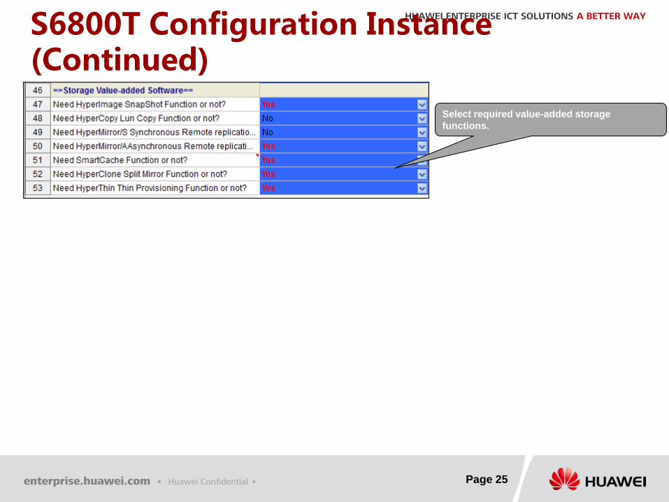
S6800T Configuration Instance (Continued)
Select required value-added storage
functions.

Copyright©2012 Huawei Technologies Co., Ltd. All Rights Reserved. The information in this document may contain predictive statements including, without limitation, statements regarding the future financial and operating results, future product portfolio, new technology, etc. There are a number of factors that could cause actual results and developments to differ materially from those expressed or implied in the predictive statements. Therefore, such information is provided for reference purpose only and constitutes neither an offer nor an acceptance. Huawei may change the information at any time without notice.
HUAWEI ENTERPRISE ICT SOLUTIONS A BETTER WAY