Ocean Energy: Global Technology Development -- Final Technical Report. Document No. t0104.
83
Implementing Agreement on Ocean Energy Systems International Energy Agency OCEAN ENERGY: GLOBAL TECHNOLOGY DEVELOPMENT STATUS March 2009 A report prepared by Powertech Labs Inc. for the IEA-OES under ANNEX I - Review, Exchange and Dissemination of Information on Ocean Energy Systems IEA-OES Document No.: T0104
-
Upload
steve-b-salonga -
Category
Documents
-
view
266 -
download
3
Transcript of Ocean Energy: Global Technology Development -- Final Technical Report. Document No. t0104.

Implementing Agreement on Ocean Energy Systems International Energy Agency
OOCCEEAANN EENNEERRGGYY:: GGLLOOBBAALL TTEECCHHNNOOLLOOGGYY
DDEEVVEELLOOPPMMEENNTT SSTTAATTUUSS
MMaarrcchh 22000099
A report prepared by Powertech Labs Inc. for the IEA-OES under
ANNEX I - Review, Exchange and Dissemination
of Information on Ocean Energy Systems
IEA-OES Document No.: T0104

2
OCEAN ENERGY: GLOBAL TECHNOLOGY DEVELOPMENT STATUS
Final Technical Report IEA-OES Document No.: T0104
Authors: Jahangir Khan and Gouri S. Bhuyan Powertech Labs Inc
12388-88th Avenue, Surrey
British Columbia, Canada, V3W 7R7
This report was contributed by Powertech Labs to the IEA-OES under ANNEX I: Review, Exchange and Dissemination of Information on Ocean Energy Systems.
Disclaimer
The OES IA, whose formal name is the Implementing Agreement for a Co-operative Programme on Ocean Energy Systems, functions within a framework created by the International Energy
Agency (IEA). Views, findings and publications of the OES IA do not necessarily represent the views or policies of the IEA Secretariat or of all its individual member countries.
Neither the authors nor the organizations participating in or funding the OES IA make any warranty or representations, expressed or implied, with respect to use of any information
contained in this report, or assumes any liabilities with respect to use of or for damages resulting from the use of any information disclosed in this document.
Availability of Report
A PDF file of this report is available at:
www.iea-oceans.org www.powertechlabs.com
Suggested Citation
The suggested citation for this report is:
J. Khan and G. Bhuyan (2009). Ocean Energy: Global Technology Development Status, Report prepared by Powertech Labs for the IEA-OES. [Online], Available: www.iea-oceans.org

3
EXECUTIVE SUMMARY
Further to the evaluation of the development of ocean energy technologies, as reported in the IEA-OES 2006 report, Review and Analysis of Ocean Energy Systems, Development
and Supporting Policies, [1], additional evaluation of the technologies and their development status was carried out during 2007 and 2008. Ocean energy conversion systems are being developed in a number of countries, as shown in Fig. 1, with the United Kingdom leading the development effort, followed by the United States. Canada and Norway also have a significant number of technology development activities. In addition to these statistics, numerous research and development initiatives are currently being pursued in various academic institutions throughout the world. Also, renewed activities toward developing small to large-scale marine energy projects can be observed within the global marine energy domain [2].
Figure 1: Country participation in ocean energy conversion system development
As part of this review, the current development status of the harnessing of ocean renewable energy resources has been analyzed. The maturity of the ocean renewable energy conversion technologies is shown in Fig. 2.

4
Figure 2: Technology maturity of various ocean energy conversion schemes
Several tidal barrage plants, with a capacity of up to 240 MW, are operating on a commercial basis worldwide, and new initiatives on these types of development are also in progress in selected countries [2]. Several ocean energy technologies are currently being operated in pre-commercial/full-scale test systems [3][4][5]. A number of demonstration projects in the range of 1 to 3 MW are awaiting deployment throughout the world, especially in the wave and tidal (marine) current conversion category. Conversion technologies for harnessing energy associated with ocean thermal gradients and salinity gradients are, however, mostly at the research and development stage.

5
TABLE OF CONTENT Executive Summary 3
List of Figures 6
1. Introduction: Technology Review 7 2. Categorization and Description of Technologies 9
2.1 Tidal Barrage Technologies 9 2.2 Tidal Current Technologies 9 2.3 Ocean Wave Technologies 11 2.4 Ocean Thermal Energy Conversion (OTEC) 17 2.5 Salinity Gradient 17 3. Comprehensive Overview of Available Technologies 19
4. Summary: Technology Status 20 4.1 Overview and Analysis of System Maturity 20 4.2 Overview of System Configurations (Power Take-Off) 21 4.3 Overview of Country Involvement 24 Acknowledgements 26 References 27
Appendix 36
A. Ocean Energy Conversion Technology/Concept at a Glance 36
B. Brief Description of the Conversion Processes 57
B1 Tidal Barrage Technologies 58
B2 Tidal Current Technologies 60
B2.1 Horizontal Axis Turbine B2.2 Vertical Axis Turbine B2.3 Hydrofoil B2.4 Other Tidal
60 63 65 66
B3 Ocean Wave Technologies 67 B3.1 OWC (Oscillating Water Column) Systems
OWC – Onshore OWC – Near-shore
OWC – Floating B3.2 Absorber Systems
Absorber – Point Absorber – Multi Point Absorber – Directional Float
B3.3 Overtopping Devices B3.4 Inverted Pendulum Devices B3.5 Other Wave Energy Systems
67 67 68 69 70 70 74 75 76 77 78
B4 Thermal Gradient Technologies 81
B5 Salinity Gradient and Hydrothermal Vent Technologies 83

6
LIST OF FIGURES
1 Country participation in ocean energy conversion system development 3 2 Technology maturity within various ocean energy conversion schemes 4 2.1 Tidal stream turbines (a) Free flow and (b) Ducted horizontal-axis turbine 10 2.2 Tidal stream turbines (a) Free flow and (b) Ducted vertical-axis turbine 10 2.3 Example of a shoreline/onshore OWC 12 2.4 A floating OWC buoy 13 2.5 A farm of linear generator-based point absorber buoys 14 2.6 A mechanical power take-off system 15 2.7 An illustration of the overtopping principle 16 2.8 An “Inverted Pendulum” wave energy device employing a pressurized
hydraulics power take-off system 16 2.9 Closed-cycle OTEC (Rankine Cycle) 17 2.10 The Pressure-Retarded Osmosis (PRO) process 18 4.1 Percentage of tidal current systems in each maturity category 20 4.2 Percentage of wave energy systems in each maturity category 20 4.3 Usage of power take-off systems among various tidal current technologies 22 4.4 Usage of power take-off systems among various wave energy technologies 23

7
1
INTRODUCTION: TECHNOLOGY REVIEW
The energy in the ocean waves is a form of concentrated solar energy that is transferred through complex wind-wave interactions. The effects of earth’s temperature variation due to solar heating, combined with a multitude of atmospheric phenomena, generate wind currents in global scale. Ocean wave generation, propagation and direction are directly related to these wind currents. On the other hand, ocean tides are cyclic variations in seawater elevation and flow velocity as a direct result of the earth’s motion with respect to the moon and the sun and the interaction of their gravitational forces. A number of phenomena relating to earth rotational tilt, rate of spinning, and interaction among gravitational and rotational forces cause the tide conditions to vary significantly over time. Tide conditions are more apparent in coastal areas where constrained channels augment the water flow and increase the energy density. The forms of ocean renewable sources can be broadly categorized into: (a) Tides (b) Wave (c) Marine Current (d) Temperature Gradient, and (e) Salinity Gradient [1]. Ocean Tides: Potential energy associated with tides can be harnessed by
building barrage or other forms of turbine-equipped construction across an estuary.
Ocean Waves: Energy associated with ocean waves can be harnessed using modular types of technologies.
Marine Current: Kinetic energy associated with tidal/marine currents can be harnessed using modular systems.
Temperature Gradient: Thermal energy due to temperature gradient between sea surface and deep-water can be harnessed using different ocean thermal energy conversion (OTEC) processes.
Salinity Gradient: At the mouths of rivers where fresh water mixes with saltwater, energy associated with the salinity gradient can be harnessed using a pressure-retarded reverse osmosis process and associated conversion technologies.
Other renewable ocean resource concepts, such as hydrothermal vents, along with hybridization of the aforementioned schemes, are also being pursued. With the advent of various novel concepts and reported success of several deployments, the ocean renewable energy sector, especially the field of tidal current and wave energy conversion technology have gained significant attention throughout the world. Many technologies are also being explored for energy uses other than electricity generation, such as, producing drinking water through desalination, supplying compressed air for aquaculture, and hydrogen production by electrolysis. Harnessing energy from tides using tidal barrages has by far the longest history of successful generation of electricity from ocean resources. It represents an older and mature technology with a potential for negative environmental impacts. In France, the La Rance Barrage has a capacity of 240 MW [10], whereas in Canada, Nova Scotia Power

8
operates a 20 MW plant [33]. Other ocean renewable energy sources, such as salinity gradient, temperature gradient and even hydrothermal vents offer further potential for extraction of renewable energy. While the resource potential is considerable [6][7][8][11][12][13][14], the systems for harvesting wave and tidal current resources are mostly in the research and development stage, with very few experiencing any kind of pre-commercial deployment. This report outlines the current progress and breadth of ocean energy technologies by providing a comprehensive listing and description of the different ocean renewable energy systems in development, with emphasis on systems based on waves and tidal currents. The information reported in the 2006 IEA-OES publication, Review and
Analysis of Ocean Energy Systems, Development and Supporting Policies [1], prepared by AEA Technology, was reviewed as part of this work. In addition, an on-line compendium of various ocean energy systems, projects, and relevant information has been made available through United States Department of Energy’s website [2]. Appendix A and Appendix B present a summary of many of these technologies and have been compiled using publicly available information during the period of 2007-2008.

9
2
CATEGORIZATION AND DESCRIPTION OF TECHNOLOGIES
2.1 Tidal Barrage Technologies Tidal barrages consist of a large, dam-like structure built across the mouth of a bay or estuary in an area with a large tidal range. As the level of the water changes with the tides, a difference in height develops across the barrage. Water is allowed to flow through the barrage via turbines, which can provide power during the ebb tide (receding), flood tide (allowing water to fill the reservoir via sluice gates during flood tide), or during both tides. This generation cycle means that, depending on the site, power can be delivered twice or four times per day on a highly predictable basis [10]. Tidal barrages represent the oldest and most mature of all the ocean power technologies. There are several commercial plants up to 240 MW in size in operation in the world. Some new construction and feasibility studies for this type of plant are underway in different parts of the world [15]. The substantial capital costs associated with construction and concerns over adverse environmental impacts make the technology somewhat unappealing in contrast to tidal current technologies. 2.2 Tidal Current Technologies Tidal current energy represents a different approach to extracting energy from tides (or other marine currents). Rather than using a dam structure, the devices are placed directly “in-stream” and generate energy from the flow of water [16]. There are a number of different technologies for extracting energy from marine currents, including horizontal-and vertical-axis turbines, as well as others such as venturis and oscillating foils. Additionally, there is a variety of methods for fixing tidal current devices in place, including seabed anchoring via a gravity base or driven piles, as well as floating or semi-floating platforms fixed in place via mooring lines. The energy available at a site is proportional to the cube of the current velocity at the site and to the cross-sectional area [17]. This means that, in general, the power that can be generated by a turbine is roughly proportional to its area, and that achieving high power outputs is dependent on having high flow velocities. For this reason, tidal current systems are best suited to areas where narrow channels or other features generate high velocity (2 to 3 m/s or more) flows. The velocity of a tidal current, and thus its power, varies throughout the day in a pattern similar to the height of the tide. Horizontal-axis turbines
Horizontal-axis turbines are perhaps the most common means of extracting power from marine currents and are somewhat similar in design to those used for wind power. Although there are a variety of approaches, including ducts, variable pitch blades and rim generators, all of these devices consist of a turbine with a horizontal-axis of rotation, aligned parallel to the current flow. These axial-flow turbines generally use a power take-
10
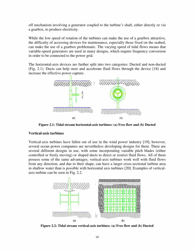
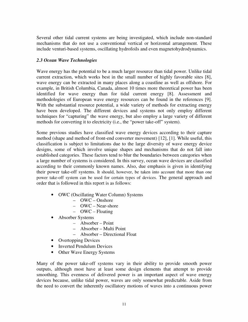
off mechanism involving a generator coupled to the turbine’s shaft, either directly or via a gearbox, to produce electricity. While the low speed of rotation of the turbines can make the use of a gearbox attractive, the difficulty of accessing devices for maintenance, especially those fixed on the seabed, can make the use of a gearbox problematic. The varying speed of tidal flows means that variable-speed generators are used in many designs, which require frequency conversion in order to be connected to the power grid. The horizontal-axis devices are further split into two categories: Ducted and non-ducted (Fig. 2.1). Ducts can help steer and accelerate fluid flows through the device [18] and increase the effective power capture.
Figure 2.1: Tidal stream horizontal-axis turbines: (a) Free flow and (b) Ducted
Vertical-axis turbines
Vertical-axis turbines have fallen out of use in the wind power industry [19]; however, several ocean power companies are nevertheless developing designs for them. There are several different designs in use, with some incorporating variable pitch blades (either controlled or freely moving) or shaped ducts to direct or restrict fluid flows. All of them possess some of the same advantages; vertical-axis turbines work well with fluid flows from any direction, and due to their shape, can have a larger cross-sectional turbine area in shallow water than is possible with horizontal axis turbines [20]. Examples of vertical-axis turbine can be seen in Fig. 2.2.
Figure 2.2: Tidal stream vertical-axis turbines: (a) Free flow and (b) Ducted
11
Several other tidal current systems are being investigated, which include non-standard mechanisms that do not use a conventional vertical or horizontal arrangement. These include venturi-based systems, oscillating hydrofoils and even magnetohydrodynamics.
2.3 Ocean Wave Technologies
Wave energy has the potential to be a much larger resource than tidal power. Unlike tidal current extraction, which works best in the small number of highly favorable sites [8], wave energy can be extracted in many places along a coastline as well as offshore. For example, in British Columbia, Canada, almost 10 times more theoretical power has been identified for wave energy than for tidal current energy [8]. Assessment and methodologies of European wave energy resources can be found in the references [9]. With the substantial resource potential, a wide variety of methods for extracting energy have been developed. The different devices and systems not only employ different techniques for “capturing” the wave energy, but also employ a large variety of different methods for converting it to electricity (i.e., the “power take-off” system).
Some previous studies have classified wave energy devices according to their capture method (shape and method of front-end converter movement) [12], [1]. While useful, this classification is subject to limitations due to the large diversity of wave energy device designs, some of which involve unique shapes and mechanisms that do not fall into established categories. These factors tend to blur the boundaries between categories when a large number of systems is considered. In this survey, ocean wave devices are classified according to their commonly known names. Also, due emphasis is given in identifying their power take-off systems. It should, however, be taken into account that more than one power take-off system can be used for certain types of devices. The general approach and order that is followed in this report is as follows:
• OWC (Oscillating Water Column) Systems – OWC – Onshore – OWC – Near-shore – OWC – Floating
• Absorber Systems – Absorber – Point – Absorber – Multi Point – Absorber – Directional Float
• Overtopping Devices • Inverted Pendulum Devices • Other Wave Energy Systems
Many of the power take-off systems vary in their ability to provide smooth power outputs, although most have at least some design elements that attempt to provide smoothing. This evenness of delivered power is an important aspect of wave energy devices because, unlike tidal power, waves are only somewhat predictable. Aside from the need to convert the inherently oscillatory motions of waves into a continuous power

12
output, wave energy devices must also adapt to changes in wave energy that will occur over a scale of hours, minutes and even between waves. This aspect could make the variability of wave devices even higher than the variability of wind, so many power take-off systems attempt to incorporate storage systems to buffer and smooth their power outputs. OWC (Oscillating Water Column) Systems Air turbines are used almost exclusively by the oscillating water column (OWC) type wave energy devices for converting fluid power into rotary-mechanical power [21]. The basic form of an OWC is a mostly closed chamber that is open to the sea at the bottom and open to the air via one or more air turbines. As waves impact the device, the water level inside the chamber rises and falls, compressing and expanding the air and driving it through the air turbine. Since the air direction reverses halfway through each wave, a method of rectifying the airflow is required; although systems employing multiple turbines with one-way valves have been used, the currently favored method involves the use of a “self-rectifying” turbine that spins in only one direction regardless of the direction of airflow. The most popular design is known as the Wells Turbine, and involves symmetrically shaped airfoils mounted at 90o to the airflow; however, other turbine designs that use variable-pitch turbine blades are also in use. Although the flywheel motion of the turbine does provide some energy storage, the overall output of an air turbine is generally highly variable [22]; careful design choices and a significant amount of power electronics will probably be required in order for an OWC to be connected to the grid.
Figure 2.3: Example of a shoreline/onshore OWC [12]

13
Figure 2.4: A floating OWC buoy [23]
Absorber Systems
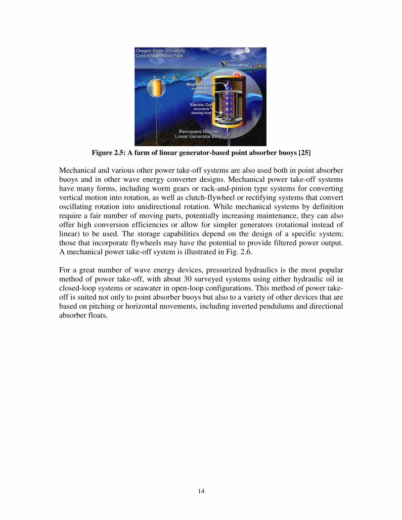
The basic design of a point absorber involves a floating buoy whose mass and buoyancy are selected so that the buoy resonates strongly with the waves. The waves will then cause this buoy to undergo relative movement against a fixed reference; this can be a moored link to the seabed, another buoy (with a different resonance frequency), or a flat damper plate that remains relatively stable. The linear generator is the most direct method for harvesting this energy, as it converts the linear motions between the buoy and its reference directly into electricity. The basic form of a linear generator involves a piston containing a set of permanent magnets and a stator consisting of coils arranged in tubular form around the piston. Typically, one part of the point absorber (either the oscillating or the damped portion) will form or be connected to the piston, and the other will be the stator. This design possesses substantial advantages in that it brings the number of moving parts as well as the overall complexity of the power take-off system down to a minimum. There are also, however, disadvantages with this design, as large permanent magnets can be costly and there is no provision for any energy storage to smooth the output. In fact, the energy output of a linear generator varies significantly over time and will thus almost always need a rectifier-inverter [24] in order to provide useful power. An example of a point absorber buoy employing a linear generator can be seen in Fig. 2.5. Directional absorber floats are similar to point absorbers, except that they have their best efficiency for only one direction, but can also convert wave power from other directions.
14
Figure 2.5: A farm of linear generator-based point absorber buoys [25]
Mechanical and various other power take-off systems are also used both in point absorber buoys and in other wave energy converter designs. Mechanical power take-off systems have many forms, including worm gears or rack-and-pinion type systems for converting vertical motion into rotation, as well as clutch-flywheel or rectifying systems that convert oscillating rotation into unidirectional rotation. While mechanical systems by definition require a fair number of moving parts, potentially increasing maintenance, they can also offer high conversion efficiencies or allow for simpler generators (rotational instead of linear) to be used. The storage capabilities depend on the design of a specific system; those that incorporate flywheels may have the potential to provide filtered power output. A mechanical power take-off system is illustrated in Fig. 2.6. For a great number of wave energy devices, pressurized hydraulics is the most popular method of power take-off, with about 30 surveyed systems using either hydraulic oil in closed-loop systems or seawater in open-loop configurations. This method of power take-off is suited not only to point absorber buoys but also to a variety of other devices that are based on pitching or horizontal movements, including inverted pendulums and directional absorber floats.

15
Figure 2.6: A mechanical power take-off system [26]
It should be stated that whenever seawater (as against other hydraulic fluids) is used in pressurized hydraulics power take-off systems, a Pelton turbine (rather than a hydraulic motor) is employed. Instances of such designs can be found in Aquabuoy device [151] and COPPE/Hyperbaric system [210]. The popularity of using pressurized hydraulics for power take-off is partly due to its particular suitability for the movements of wave devices; the pitching of a lever arm or the vertical motion of a buoy against a stationary reference can easily be used to drive a piston in a pump or a hydraulic ram. Another advantage is the ease of incorporating energy storage, which can be done using a high-pressure accumulator or a set of high-pressure/low-pressure accumulators. For example, a Chinese oscillating buoy incorporated a 2.8 kWh (10 MJ) energy buffer in order to smooth its output [27]. The generation of electricity is usually done by draining the pressurized accumulator via a variable speed hydraulic motor with variable geometry. This aspect presents the final advantage, flexibility, in that the output of multiple devices can easily be combined into a single accumulator and generator or directed to an onshore facility. Using a smaller number of larger generators increases efficiency and decreases the amount of maintenance required, and placement of the generation equipment onshore can provide for even easier maintenance and monitoring. In seawater-based devices, the pressurized output can also easily be used for desalination via reverse osmosis or even for aquaculture. The disadvantage of aggregating multiple

16
device outputs, or directing the output onshore, is that pressure losses along a long pipe can be significant; however, as long as pipeline lengths are minimized in the design, pressurized hydraulics can still provide high efficiencies. Care must also be taken with closed-loop devices to prevent leaks of hydraulic oil into the surrounding environment, and to use fluids with minimal environmental impact when possible. Overtopping Devices
Overtopping devices generally use reflector arms to store the seawater in an accumulator that induces a water head. This static head is then used to run water turbines (The term
“water turbine” may seem unusual, as in the case of tidal current systems and tidal
barrages, almost all of the devices are quite literally water turbines. In wave energy
systems, however, extracting energy from a fluid flow via a turbine represents a distinct
power take-off system and is thus included as such) and subsequent generation of electrical power. Amongst many different types of water turbines, the low-head “Kaplan” type turbines are the most common choice. This principle is illustrated below in Fig. 2.7. The reservoir provides some energy storage, but the head and flow rate available to the turbines will change as the reservoir drains and fills, making smooth power output more difficult [29]. Overtopping devices do possess an advantage in that their turbine technology has already been in use in the hydropower industry for long time and is thus well understood.
Figure 2.7: An illustration of the overtopping principle [28] Inverted Pendulum Devices
An inverted pendulum is a device that uses a buoyant float or lever arm, which is generally anchored to the seabed. Waves passing over the device cause it to pitch back and forth, actuating power take-off systems such as hydraulic pumps. Fig. 2.8 provides an example of a seawater-based inverted pendulum system.
Figure 2.8: An “Inverted Pendulum” wave energy device employing a pressurized
hydraulics power take-off system [28]

17
This movement in the front-end oscillator is in turn converted into linear piston motion and pressurized fluid is pumped to the embedded/on-shore generating station to drive the electric generators. While various small-scale prototypes are being tested, the true extent of these devices’ effectiveness is yet to be realized. Other Wave Energy Systems Many ocean energy devices use multiple power take-off mechanisms and may have somewhat unique principles of operation. While most of these systems are at design or research and development phase, several select technologies are approaching commercial/pre-commercial deployment (such as the Pelamis wave energy device [4]). Further refinement is needed in classifying these devices into more generic categories. 2.4 Ocean Thermal Energy Conversion (OTEC)
Ocean thermal energy conversion (OTEC) makes use of the temperature difference between the warm surface of the ocean and the colder layers underneath. Due to solar heating, the amount of energy available in the temperature gradient between hot and cold seawater can be substantially larger than the energy required to pump the cold seawater up from the lower layers of the ocean. The warm water from the surface is used to boil a working fluid (or, in open cycle systems, the seawater itself under low pressure), which is then run through a turbine and condensed using cold seawater pumped up from the depths. Fig. 2.9 shows the fluid cycle of a closed system. OTEC is best suited to areas near the equator, where the intense solar radiation warms the surface significantly [30]; however, it is included in this report in order to demonstrate the full range of ocean power systems available.
Figure 2.9: Closed-cycle OTEC (Rankine Cycle) [29]
2.5 Salinity Gradient Salinity gradient power makes use of the potential energy available when saltwater and freshwater mix. The pressure induced by the movement of water across a membrane can be used to run turbines via a process known as “Pressure-Retarded Osmosis.” This process is illustrated below in Fig. 2.10. Another system is based on using freshwater

18
upwelling through a turbine immersed in seawater, and one involving electrochemical reactions is also in development. Many areas exist where industrial users (such as sewage treatment plants) discharge substantial volumes of fresh or low-salinity water into the ocean; such locations could be ideal for implementing prototype salinity gradient systems.
Figure 2.10: The Pressure-Retarded Osmosis (PRO) process [31]
In addition to the classification presented in the aforementioned discussion, several other principles of energy conversion (hydrothermal vents, algal biomass, etc.) are being investigated. Hydrothermal vents offer access to high-energy geothermal resources via the superheated water that emerges at these sites. Some research into the energy available at sites in Mexico has been done [32]; however, the development of this type of energy is still at a very early stage.
19
3
COMPREHENSIVE OVERVIEW OF AVAILABLE TECHNOLOGIES
In this chapter, initiatives undertaken by various ocean energy research, development and demonstration (RD&D) entities are surveyed and described using Appendix A and Appendix B. Discussions on various projects that are currently in operation, along with evaluation of several other systems currently being developed are outlined. (Generally these discussions are separated by the technology developer, except in cases where one company has several distinct technologies.) Projects that are no longer in operation, but which represent a distinct technology, are also included. Some conversion concepts that are no longer pursued are also presented in this report. These technologies are separated by the type of ocean energy they capture: tidal potential energy (via barrages), tidal currents, wave energy, ocean thermal energy, salinity gradients and hydrothermal vents. Some devices are considered hybrid systems as these are designed to convert more than one resource types (e.g., wave and tide concurrently); such devices are categorized according to their main source of power generation. The ocean energy devices, as studied in this report, are separated into six broad technology-maturity categories, each representing a different stage of development:
• Commercial: Technologies that have been operating on commercial basis for a significant period of time.
• Pre-commercial: Systems that are claimed to be in such a level of advancement where commercial deployment is reasonably expected within few years.
• Full-scale: Devices or concepts that have seen at least one full-cycle development regardless of their scope of commercial production or present status of progress.
• Part-scale (Sea): Technologies that are reported to have undergone tests in the sea (Part of the full system or part-scale model of the prototype).
• Part-scale (Tank): Devices, concepts and prototypes that are in the research and development phase undergoing tests in the laboratory environment.
• Concept Design: Systems that have attracted attention due to their unique and promising features, which may or may not be realized in the future.
A short pictorial form of this survey along with an indication of their stages of development is given in Appendix A, followed by a brief description of each of these technologies in Appendix B. It should be noted that with the present dynamic and ever-changing status of the ocean energy sector, this categorization and overview requires further updates.

20
4
SUMMARY: TECHNOLOGY STATUS
Based on the survey presented in Chapter 3, a number of aspects significant to the ocean energy sector are identified in this chapter. These observations are presented with a view to indicating the trends in system design, technology maturity and country participation within the emerging global marine energy sector. 4.1 Overview and Analysis of System Maturity The maturity of systems falls across a wide spectrum, with most in the intermediate stages of development. The maturity levels of tidal current and wave energy systems are shown in Fig. 4.1 and Fig. 4.2, respectively.
Figure 4.1: Percentage of tidal current systems in each maturity category
Figure 4.2: Percentage of wave energy systems in each maturity category

21
4.2 Overview of System Configurations (Power Take-Off)
Tidal current systems display a smaller variety, as most tidal current systems have converged on a few turbine designs. Given that this sector of technological advancement is not yet mature, a large number of systems have not identified the type of power take-off/generator to be used. Most known tidal systems use a rotary generator of some type, connected either directly or via a gearbox, with only a few using pressurized hydraulics instead. Among wave devices, certain types are inherently designed for only one power take-off system; OWCs use only air turbines, and overtopping devices use only low-head water turbines. Among the other wave systems, however, the power systems in use are highly diverse. Although pressurized hydraulics is the most common solution, especially among point absorbers, mechanical systems, linear generators and other power take-off systems are also in use. The full range of power take-off systems in use by tidal and wave energy systems are detailed in Fig. 4.3 and Fig. 4.4, respectively. Relatively few wave energy systems are still at the concept design stage; most system developers have performed at least basic wave-tank tests. A large number of systems have also undergone testing at sea. Among the tidal current systems, more systems are in the concept design stage; however, the same number has also proceeded forward to testing at sea. Currently, around six wave systems and one tidal current system have been developed as full-sized prototypes, and have substantial potential for development as commercial systems. The full production category includes only a few systems: The various tidal barrages in operation and the thermal gradient (OTEC) plants in India that are currently used for desalination. The progress of specific systems, highlighting the leaders in terms of developmental maturity, is described in more detail below. Tidal barrages have been the most successful ocean power facilities to date, with the La Rance and Annapolis barrages in particular demonstrating significant amounts of power generation as well as long-term operation. Development work on new barrages continues throughout the world, especially in the Republic of Korea, and technologies like Tidal Delay and Offshore Tidal Lagoons offer a more environmentally sensitive alternative to traditional barrages. It is likely that tidal barrages will continue to represent the majority of total ocean power generation during the near future.

22
Figure 4.3: Usage of power take-off systems among various tidal current energy
technologies Tidal current energy offers a great deal of promise, especially during the early stages when the highest-energy sites are all still available for the implementation of new systems. Among the horizontal-axis turbines, the MCT SeaFlow and the Hammerfest turbine have deployed 300-kW prototypes, and the latter provides power to the local grid. The MCT Seagen has completed its construction and a full-scale pre-commercial unit has been deployed. The Clean Current system, Open-Centre system, and the Tocardo system have all been deployed as test prototypes at sea, and the Underwater Electric Kite and Verdant Power turbine have also undergone testing. The Evopod, SRTT and TidEl are undergoing scale testing as well, and may be able to deploy prototypes in the near future. The Enermar Kobold turbine is one of the more advanced devices in the vertical-axis turbine category, with a full-scale, grid-connected prototype deployed and generating power. Various designs of vertical-axis turbines have also been deployed in China, and testing at sea of unconventional devices like the HydroVenturi has also occurred. Among the other vertical-axis turbine systems, the Davis Hydro turbine, the EnCurrent turbine, and the Gorlov Helical turbine have all undergone scale testing at laboratory or sea. Overall, these technologies represent the current norm of tidal current development. Other devices, such as the Lunar Energy RTT, are at test and development stages with various levels of testing completed. Wave energy devices have a wide variety of different methods for extracting wave energy, each of which allows for different types of power take-off. Air turbines, used almost exclusively in OWCs, appear in a number of systems. Several onshore projects

23
have undergone long-term, grid-connected operation at full scale, including the Pico OWC plant and the Islay Limpet 500.
Figure 4.4: Usage of power take-off systems among various wave energy technologies
A number of other systems, most of which were grid-connected, have been tested at sea: the Oceanlinx/Energetech OWC, the Vizhinjam OWC in India, the GIEC OWC systems in China, and the OWC systems developed in Japan. These systems are all either the nearshore or onshore type. Several offshore OWC systems are at the part-scale testing stage, including the Sperboy and MRC1000, the OE Buoy and the OWEL “Grampus.” A wide variety of other systems based on OWCs are currently in the earlier developmental stages. Among the linear generator-based systems, the Archimedes Wave Swing has tested a prototype at sea and further devices are under development. At a smaller scale, researchers at Oregon State University have been investigating and developing linear generator technology as well as point absorber buoys. Along with the OSU designs, the Trident Energy Converter is also in the small-scale stage of testing. Several other systems are currently in the earlier stages of development. A number of ocean power systems have unspecified power take-off mechanisms. The OPT Powerbuoy is a rather advanced technology, with two 40-kW units deployed at sea and several installations in the planning stages. Two other floating buoys, the Manchester Bobber and the WET-NZ wave device, have undergone scale testing, and many other designs, such as the Syncwave device, are in the initial stages of development.

24
A large number of wave devices use pressurized hydraulics for power take-off. The leader in this category is the Pelamis device. At present, a wave farm consisting of three Pelamis devices is being operated along the coast of Portugal [4]. There are also a number of other devices that have completed scale testing at sea, including the McCabe Wave Pump, the SDE onshore wave absorber, the GIEC onshore oscillating buoy, the FO3 SEEWEC, the Greek Wave Energy Point Absorber, the Wave Star and the WaveRoller. The Wave Star has provided power to the grid, whereas the Greek Wave Energy Point Absorber and the McCabe Wave Pump have only demonstrated the delivery of pressurized seawater. The AquaBuOY and Wavebob systems have also been tested as prototypes. A large number of devices, including the Duck, are in development but have not yet undergone full-scale trials. Most of the wave devices that use water turbines for power take-off are based on overtopping concepts; however, a few other approaches also exist. The Wave Dragon is the leading device in this category; it has been deployed at sea as a comprehensive test prototype and it has provided power to the local grid. Another device, the WaveRotor, was connected to the grid during its part-scale testing at sea. Devices in the earlier stages of development include the Seawave Slot-Cone Generator (SSG) and the WavePlane. OTEC has been demonstrated in several plants; those in the US and Japan have demonstrated its viability for power generation, and those in India have provided significant amounts of fresh water. Though OTEC technology has limited potential for areas like the Pacific Northwest that do not have high sea-surface temperatures, other uses, such as heating, cooling and desalination processes, may take advantage of this technology. Salinity gradient is still at a relatively early stage; while the Pressure-Retarded Osmosis (PRO) process shows potential, significant advances in membrane technology will likely be required in order to make the technology feasible for large-scale generation. Hydrothermal vent power is at a very early stage of development and further progress in this area need to be realized through testing and demonstration. 4.3 Overview of Country Involvement The development of ocean energy systems is spread widely across a number of countries, with the United Kingdom and the United States each representing a substantial portion. The UK is leading the development effort, with a significant lead over the US in number of systems. Canada, Norway, Australia and Denmark also have a significant number of systems in development. Although only a limited number of systems are under development in Portugal, it should be noted that many more systems, including the Pelamis and the Archimedes Wave Swing, have undergone deployment and testing there. Overall, 25 countries (including Portugal and Denmark for the archipelagos of the Azores and the Faroe Islands, respectively) are participating in the development of ocean power.

25
As shown in Figure 2, there are more wave systems than tidal current systems, and wave and tidal current systems significantly outnumber other system types. The large number of wave devices is likely due to two factors: Firstly, the potential resource available is much higher for wave than it is for tidal current. Secondly, there is a wide variety of different methods for extracting wave energy, whereas tidal current systems have mostly converged on a few different turbine designs. The number of tidal current systems is likely due to the simplicity of the technology, which is very similar to the technologies and techniques used in wind power. Overall, wave energy and tidal current energy are the focus of current ocean power development efforts. A large number of prototypes have been developed in the UK, with only a few amongst the other countries. However, systems at various stages of development are present in almost every country, demonstrating the wide distribution of technological progress.

26
ACKNOWLEDGEMENTS
Assistance is acknowledged for funding from Bonneville Power Administration of USA, and BC Hydro, BC Transmission Corporation and Powertech Labs of Canada, for enabling the technology review and analysis of the information. The members of the IEA-OES provided important feedback on this report. In particular, inputs from Dr. Teresa Pontes of the National Laboratory of Energy & Geology (LNEG), Portugal, Prof. Antonio Falcão of the Technical University of Lisbon, Portugal, and Dr. Ana Brito e Melo of the Wave Energy Centre (WEC), Portugal, are appreciated.

27
REFERENCES
[1] AEA Technology, IEA-OES. (2006, June) Review and Analysis of Ocean Energy Systems,
Development and Supporting Policies [2] U.S. Department of Energy, Marine and Hydrokinetic Technology Database, [Online]. Available:
http://www1.eere.energy.gov/windandhydro/hydrokinetic/default.aspx [3] Antonio F. de O. Falcao, The Development of Wave Energy Utilization, [Email Correspondence];
IDMEC, Institute Superior Tecnico, Technical University of Lisbon, Lisbon, Portugal [4] Pelamis Wave Power Ltd-Press Release. (2008, 23 Sept.); World's First Commercial Wave Power
Project goes live; [Online]. Available: http://www.pelamiswave.com/news.php?id=26 [5] Marine Current Turbines Ltd. (2008, 17 Nov.); SeaGen Enters Final Stage of Commissioning,
[Online]; Available: http://www.marineturbines.com/3/news/ [6] EPRI. (2005) Wave Power Feasibility Study, pp. 3-5. [Online]. Available: http://www.epri.com [7] M.J.Khan, G. Bhuyan, A. Moshref, K. Morison, “An Assessment of Variable Characteristics of the
Pacific Northwest Regions Wave and Tidal Current Power Resources, and their Interaction with Electricity Demand & Implications for Large Scale Development Scenarios for the Region,” Tech. Rep. 17485-21-00 (Rep 3), Jan. 2008, [Online], Available: http://www.powertechlabs.com/cfm/index.cfm?It=106&Id=58
[8] Canadian Hydraulics Centre, National Research Council Canada. (2007, Nov.) Inventory of Canada’s Marine Renewable Energy Resources; Tech. Report: CHC-TR-041. [Online]. Available:http://www.oreg.ca/docs/Atlas/TritonCanadaTidalPowerMay2006.pdf
[9] M.T. Pontes, “Assessing the European Wave Energy Resource”. Journal of Offshore Mechanics and
Arctic Engineering, vol. 120, p.226-231 (1998). [10] Jean Pierre Frau. (2005) La Rance, a successful industrial scale experiment,, IEEE Transactions on
Energy Conversion, 1993, vol. 8: pp. 552-558. [11] EPRI. (2007, July) World Energy Council, ”Tidal Energy”. [Online]. Available:
http://www.worldenergy.org/wec-geis/publications/reports/ser/tide/tide.%asp [12] T. W. Thorpe, “A Brief Review of Wave Energy: Department of Trade and Industry,” U.K., Tech.
Rep. Rep. ETSU-R120, May 1999. [13] Gouri S. Bhuyan, “International Energy Agency’s Ocean Energy Systems (IEA-OES) Implementing
Agreement,” in IEA NEET Workshop, 2007, Ed., Brasilia, Nov. [14] NASA. (2007, Nov.). [Online]. Available: http://science.hq.nasa.gov/missions/satellite 14.htm [15] Kwang-Soo Lee. (2006) Tidal and Tidal Current Power Study in Korea, pp. 6-27, 36-43.
[Online].Available: http://www.pugetsoundtidalpower.com [16] Down TO Earth, Science and Environment Online, Vol15, No.3. (2006, June 20) First-ever tidal
plant in Sunderbans in West Bengal. [Online]. Available: http://www.downtoearth.org.in/fullprint.asp
[17] M. Gorlov. (2001) Tidal Energy, pp. 2956-2960. [Online]. Available: http://www.gcktechnology.com
[18] Simon Meade. (2005, October) Lunar Energy - harnessing tidal power,” Hydrokinetic & Wave Energy Technologies - Technical & Environmental Issues Workshop, pp.2-3, 6-9. [Online]. Available: http://www.hydropower.id.doe.gov/hydrokinetic wave/pdfs/day1/06 ducted turbine.pdf
[19] Danish Wind Industry Association. (2007, June) Wind Turbines: Horizontal or Vertical Axis Machines. [Online]. Available: http://www.windpower.org/en/tour/design/horver.htm
[20] Edinburgh Designs Ltd. (2006) Variable Pitch Foil Vertical Axis Tidal Turbine, pp. 8-10. [Online]. Available: http://www.dti.gov.uk.
[21] L.M.C. Gato and R. Curran, “The Energy Conversion Performance of Several Types of Wells Turbines Designs”, Proc. Institutions of Mechanical Engineers, Part A, Journal of Power Engineering, Vol. 211, nº A2, p 133-145, 1997.
[22] EPRI. (2007, June) Indian Wave Energy, pp. 3-5. [Online]. Available: http://www.niot.res.in/m1/mm1.html
[23] Embley Energy Ltd. (2007, June) SPERBOY Wave Energy Converter. [Online]. Available: http://www.sperboy.com/

28
[24] Oskar Danielsson. (2003) Design of a Linear Generator for Wave Energy Plant, pp. 18-30. [Online].Available: http://www.el.angstrom.uu.se.
[25] Annette von Jouanne and Ted Brekken. (2005) Overview of Wave Energy Activities at Oregon State University, pp. 2-4. [Online]. Available: http://www.eecs.oregonstate.edu/msrf/images/Overview%20of%20Wave%20Energy%20Activities%20at%20OSU.pdf
[26] UMIP. (2007, June) The Manchester Bobber. [Online]. Available: http://www.manchesterbobber.com/manchesterBobber.htm
[27] Liang Zhang. (2006, May) Relevant Ocean Energy Activities in China,pp.16-35, Canada and the world of ocean renewable energy symposium. [Online]. Available: http://www.oreg.ca
[28] Aquamarine Power. (2007, May) Clean Reliable Energy that Doesn’t Cost the Earth. [Online]. Available: http://www.aquamarinepower.com/
[29] Wilfried Knapp et. al. (2005) Considerations for Water Turbines to be used in Wave Energy Converters, pp. 4-9. [Online]. Available: http://www.wave-energy.net.
[30] L. A. Vega. (1999) Ocean Thermal Energy Conversion (OTEC),pp. 1-6,11. [Online]. Available: http://www.otecnews.org
[31] EPRI. (2005) The Salinity Power Project, pp. 2-6, 11. [Online]. Available:http://www.tf.uni-kiel.de/matwis/abetz/Salinity Power.pdf
[32] Gerardo Hiriart. (2007) Progress on Marine Energy in Mexico, pp. 16-32. [Online]. Available: www.spok.dk/seminar/CAOEMexico 17.pdf.
[33] Nova Scotia Power. (2005) Nova Scotia power...a tidal power pioneer, Electrical Line, 2002, vol. March/April: pp. 28-30. [Online]. Available: http://www.electricalline.com
[34] L. B. Bernshtein. (1969) Problem of the Utilization of Tidal Energy and the Experimental Kislaya Guba Tidal Power Plant, pp. 12-18,springerlink database.
[35] EDF. (2006) The Rance Tidal Power Plant, Power from the Ocean. [Online]. Available: http://www.edf.fr/html/en/decouvertes/voyage/usine/retour-usine.html
[36] Clive Baker and Peter Leach, ESS Consulting. (2006) Tidal Lagoon Power Generation Scheme in Swansea Bay, pp. 1-3. [Online]. Available: http://www.dti.gov.uk.
[37] Tidal Electric. (2007) Tidal Electric. [Online]. Available: http://www.tidalelectric.com/ [38] Choe Sang-Hun. (2007) As Tides Ebb and Rise, South Korea Prepares to Snare Them. [Online].
Available: http://www.iht.com/articles/2007/05/31/business/bgtidal.php [39] Steve Hastings. (2005) Introduction Paper: Tidal Delay Tidal Power Generation, pp. 1-5. [Online].
Available: http://www.cleantechcom.com/images/Tidal%20Delay(R).pdf [40] (2007, June) Power That Will Run Like Clockwork. [Online]. Available:
http://www.redorbit.com/news/business/964844/power that will run like c%lockwork/index.html [41] Oceanflowenergy. (2007, June) Oceanflowenergy. [Online]. Available:
http://www.oceanflowenergy.com/ [42] The Institution of Engineering and Technology. (2007, June) Tidal Power Company Eyes Scottish
Waters. [Online]. Available: http://www.iee.org/oncomms/sector/power/SectionNews/Object/ 93F29E78-AF6%5-81D1-C5FF938583AADF62
[43] Hammerfest Strom AS. (2007, June) Tidekraft. [Online]. Available: http://www.e-tidevannsenergi.com/
[44] Scotrenewables. (2007, June) Scotrenewables - Energy Solutions for the Future. [Online]. Available: http://www.scotrenewables.com/marine.html
[45] Jeremy Thake, IT Power. (2005) Development, Installation and Testing of a Large-Scale Tidal Current Turbine,pp. 19-26, 33-43. [Online]. Available: http://www.dti.gov.uk
[46] David Ainsworth and Jeremy Thake, Marine Current Turbines Ltd. (2006, June) Preliminary Works associated with 1MW Tidal Turbine, pp. 23-34. [Online]. Available: www.dti.gov.uk.
[47] MCT Ltd. (2007, June) Marine Current Turbines. [Online]. Available: http://www.marineturbines.com/home.htm
[48] JA Consult Ltd. (2004) The Monitoring, Operation and Assessment of a semi-Submersible Tidal Stream Prototype, pp. 6-9, 18-22. [Online]. Available: www.dti.gov.uk.
[49] TidalStream. (2007, June) Marine Power Ocean Tidal Stream Energy. [Online]. Available: http://www.teleos.co.uk/Home.htm
[50] (2007, June) Tidal Power to be Commercialized. [Online]. Available: http://www.ntnu.no/ich-cgi-bin/news.cgi?selection=show&nr=132

29
[51] Statkraft. (2007, June) What is Tidal Power? [Online]. Available: http://www.statkraft.com/pub/innovation/teknologiutvikling i statkraft/%tidevannskraft/index.asp
[52] Tidal Generation Limited. (2007, June) Tidal Generation Limited - Capturing Energy in Deep Water. [Online]. Available: http://tidalgeneration.co.uk/index.html
[53] Swanturbines. (2007, June) Swanturbines - Energy from Flowing Water. [Online]. Available: http://swanturbines.co.uk/
[54] Dana Childs. (2007, June) New Approach to Power from Waves, Tides and Rivers? [Online]. Available: http://www.insidegreentech.com/node/357
[55] Bourne Energy. (2007, June) Bourne Energy - Clean, Safe and Sustainable. [Online]. Available: http://bourneenergy.com/
[56] Tidal Hydraulic Generation Ltd. (2005, Dec.) Tidal Hydraulic Generators - Clean, Efficient, Sustainable Energy. [Online]. Available: http://thglimited.com/
[57] (2005) A Brief Summary of the Pembrokeshire Tidal Energy Project, pp. 2-7. [Online]. Available: www.socme.org/socmedownloads/pembroke%20tidal.pdf
[58] Ralph Manchester. (2007, June) The TidEl Floating Free-Stream Tidal Turbine System. [Online]. Available: http://events.sut.org.uk/past events/2006/061108 ab/Ralph Manchester/pr%esentation.htm
[59] (2007, June) TidEl Tidal Turbines. [Online]. Available: http://www.reuk.co.uk/TidEl-Tidal-Turbines.htm
[60] SMD Hydrovision. (2007, June) TidEl Tidal Stream Generator. [Online]. Available: http://www.smdhydrovision.com/products/?id=27
[61] Centre for Renewable Energy Sources. (2006) Ocean Energy Conversion in Europe, pp. 16, 30. [Online]. Available: www.wave-energy.net
[62] Teamwork Technology. (2007, June) Successful Tidal Turbine Test. [Online]. Available: http://www.teamwork.nl/
[63] Verdant Power. (2007, June). [Online]. Available: http://verdantpower.com/ [64] Dana Childs. (2007, June) Verdant Deploys Tidal Power Array in New York. [Online]. Available:
http://www.insidegreentech.com/node/1028 [65] Renewable Energy for Race Rocks. (2007, June). [Online]. Available:
http://www.racerocks.com/racerock/energy/tidalenergy/tidalenergy.htm [66] Clean Current Power Systems Incorporated; 405 - 750 West Pender Street; Vancouver, British
Columbia; Canada V6C 2T7. (2007, Nov.). [Online]. Available: URL:http://www.cleancurrent.com/ [67] IEA-OES. (2005) IEA-OES Annual Report 2006, pp. 7, 18-19. [Online]. Available: http://www.iea-
oceans.org [68] Kinetic Energy Systems. (2007, July) Kinetic Energy Systems: Providing Renewable Energy
Resource Alternatives for the Future. [Online]. Available: http://www.kineticenergysystems.com/default.asp
[69] (2007, July) Marenergie: A Resource of Bretagne...Marine Energy, pp. 6-10. [Online]. Available: http://www.energie.region-bretagne.fr/DOCS/69.pdf.
[70] OpenHydro Group Ltd. (2007, June) OpenHydro. [Online]. Available: http://www.openhydro.com/home.html
[71] Gavin Daly. (2007, June) Rise of Tidal Power as OpenHydro Seals 1.8m Deal. [Online]. Available: http://archives.tcm.ie/businesspost/2007/02/25/story21209.asp
[72] Naval Surface Warfare Center Carderock Division (NSWCCD). (2004) Development and Installation of an Open-Center Turbine for Gulf Stream Power Generation, pp. 10-14. [Online]. Available: http://www.epri.com
[73] Roger Bedard. (2005) Survey and Characterization - Tidal In Stream Energy Conversion (TISEC) Devices, pp. 1-2, 176-181. [Online]. Available: http://www.epri.com
[74] Bob Davidson. (2007) A Feasibility Study: Tidal Power Generation for a Remote, Off-Grid Community on the British Columbia Coast, pp. 51, 74-75. [Online]. Available: http://www.oreg.ca
[75] Lunar Energy. (2007, June) Lunar Energy - Harnessing Tidal Power. [Online]. Available: http://www.lunarenergy.co.uk/index.htm
[76] Triton Consultants Ltd., “Green Energy Study for British Columbia-Phase 2: Mainland Tidal Current Energy, Report for BC Hydro, Engineering, Vancouver BC,” Oct 2002.
[77] Philippe Vauthier. (2007, June) Kite Soars to New Depth. [Online]. Available: http://www.waterpowermagazine.com/story.asp?sectionCode=46&storyCode=20%34904

30
[78] UEK Corporation. (2007, June) UEK - A Renewable Energy Company. [Online]. Available: http://uekus.com/index.html
[79] QinetiQ Ltd. (2004) Cycloidal Tidal Power Generation - Phase 2, pp. 33-38. [Online]. Available: http://www.dti.gov.uk
[80] Blue Energy. (2007, June) Blue Energy Technology, pp. 3-5. [Online]. Available: http://www.bluenergy.com/technology.html
[81] H.N. Halvorson Consultants Ltd. (1994) Evaluation of Nova Energy Ltd’s Hydro Turbine,pp. 9-19, 22-25,. [Online]. Available: http://www.bluenergy.com
[82] Malcolm McColl. (2007, June) Harnessing the Power of Oceans and Rivers. [Online]. Available: http://www.nativejournal.ca/pages/_2007.02.pages/2007.02.Renew.Energ.ht%ml
[83] New Energy Corporation Inc. (2007, June) EnCurrent Turbines. [Online]. Available: http://www.newenergycorp.ca/index.htm
[84] M.H. Eriksson et. al. (2007, June) The Vertical Axis Kobold Turbine in the Strait of Messina - A Case Study of a Full Scale Marine Current Prototype, pp. 10-13. [Online]. Available: http://213.136.30.25/ ca-oe/info/3-2%20Construction%20of%20ENERMAR%20Kob%ald%20tidal%20current%20turbine.pdf
[85] Ponte di Archimede International S.p.A. (2007, June) Enermar. [Online]. Available: http://www.pontediarchimede.it/language us/progetti det.mvd?RECID=2&CAT%=002&SUBCAT= &MODULO=Progetti ENG&returnpages=&page pd=p
[86] Sea Power International AB. (2007, June) Memorandum Submitted by Sea Power International AB. [Online]. Available: http://www.parliament.the-stationery- ffice.co.uk/pa/cm200001/cmselect/%cmsctech/291/291ap25.htm
[87] (2007, June) Northern Exposure - Testing Tidal Turbines. [Online]. Available: http://www.waterpowermagazine.com/story.asp?sectionCode=46&storyCode=20%19602
[88] Jamais Cascio. (2007, June) Gorlov’s Helical Turbine. [Online]. Available: http://www.worldchanging.com/archives/002383.html
[89] GCK Technology. (2007, June) The Gorlov Helical Turbine. [Online]. Available: http://www.gcktechnology.com/GCK/pg2.html
[90] Verdant Power LLC and GCK Technology Inc. (2007, June) [91] Neptune Renewable Energy. (2007, June) Neptune Renewable Energy. [Online]. Available:
http://www.neptunerenewableenergy.com/index.htm [92] Coastal Hydropower Corporation. (2007, June) Coastal Hydro Power. [Online]. Available:
http://www.coastalhydropower.com/ [93] Atlantisstrom. (2007, June) Atlantisstrom - Regenerative Energy. [Online]. Available:
http://www.atlantisstrom.de/index english.html [94] WWTurbine (2009, March), Water Wall Turbine . [Online]. Available: http://www.wwturbine.com/ [95] Stephen Salter. (2007, June) Proposal for a Large, Vertical-Axis Tidal-Stream Generator with Ring-
Cam Hydraulics. [Online]. Available: http://www.mech.ed.ac.uk/research/wavepower/tidal%20shs% 20Patras%2098%2%0paper/Proposal%20for%20a%20large%20vertical%20axis%20etc.htm
[96] BioPower Systems Pty. Ltd. (2007, June) BioPower Systems - Biologically Inspired Ocean Power Systems. [Online]. Available: http://www.biopowersystems.com/
[97] Andrew Mackay. (2007, June) Submission to the Royal Society of Edinburgh from Greenheat Systems Limited - Gentec Venturi. [Online]. Available: http://www.royalsoced.org.uk/enquiries/energy/evidence/Greenheat System%s Ltd.pdf
[98] Tidal Sails AS. (2007, June) Tidal Sails. [Online]. Available: http://www.tidalsails.com/index.html [99] New Tidal Power Station to Surpass the Rest. (2007, June). [Online]. Available:
http://perseus.herts.ac.uk/uhinfo/extrel/press-office/press--releases/p%r-070405-hm.cfm [100] Peter O’Donnell. (2007, June) Update ’05: Ocean Wave and Tidal Power Generation Projects in San
Francisco pp. 9-13, . [Online]. Available: http:// [101] HydroVenturi Ltd. (2007, June) HydroVenturi. [Online]. Available:
http://www.hydroventuri.com/news.php [102] Pulse Generation Ltd. (2007, June) Pulse Generation: Developing New Renewable Energy
Technologies Using Tidal and Hydro Power. [Online]. Available: http://www.pulsegeneration.co.uk/index.asp

31
[103] The Engineering Business Ltd. (2005) Stingray Tidal Stream Energy Device - Phase 3, pp. 45-65, 93-99. [Online]. Available: http://www.engb.com
[104] ——. (2007, June) Stingray Tidal Stream Energy Device - Phase 2, pp. 16-22, 43-48. [Online]. Available: http://www.engb.com
[105] Neptune Systems. (2007, June) Neptune Systems Online - Power from Water. [Online]. Available: http://www.neptunesystems.net/
[106] T. Heath. (2007, June) Islay Limpet Project Monitoring Final Report,pp. 5-21, 27-35. [Online]. Available: http://www.consumer.gov.uk
[107] Wavegen. (2007, June) Research into the Further Development of the Limpet Shoreline Wave Energy Plant, pp. 1-2, 91-92. [Online]. Available: http://www.consumer.gov.uk.
[108] Sarmento, et. al. (2006) Results from Sea Trials in the OWC European Wave Energy Plant at Pico, Azores, pp. 1-2, 5. [Online]. Available: http://www.pico-owc.net
[109] F. Neumann et. al. (2006, Nov.) Pico OWC power plant: Refurbishment project, monitoring and performance,4th CA-OE Workshop, pp.3-12,.
[110] (2007, June) Use of Wave Energy. [Online]. Available: http://www.uni-leipzig.de/_grw/welle/wenergie 3 80.html
[111] SeWave Ltd. (2007, June) The Energy of the Ocean. [Online]. Available: http://www.sewave.fo/default.asp?sida=650
[112] Umesh Korde. (2007, June) Report on Wave Energy Conversion Projects. [Online]. Available: http://www.nsftokyo.org/ssr98-08.html
[113] Ohneda, H., Igarashi, S., Shinbo, O., Sekihara, S., Suzuki, K., Kubota, H., Ogino, H., and Morita, H., 1991, “Construction Procedure of a Wave Power Extracting Caisson Breakwater", Proc. 3rd Symposium on Ocean Energy Utilization, Tokyo, pp. 171-179
[114] Daedalus Informatics Ltd. (2007, June) Wave Energy Conversion Activator (WECA). [Online]. Available: http://www.daedalus.gr/DAEI/PRODUCTS/RET/General/RETWW1.html
[115] WaveNet, “Results from the work of the European Thematic Network on Wave Energy, European Community, Tech. Rep. ERK5-CT-1999-20001, 2000-2003, URL: http://www.oreg.ca/docs/WaveNet%20Full%20Report(11.1).pdf.
[116] Oceanlinx Ltd., ABN 85077104404;PO Box 116;Botany NSW 1455;Australia. (2007, Nov.). [Online]. Available: www.oceanlinx.com.au/uploads/OceanlinxSubmitsApplicationtoFERCPKFINAL.p%df
[117] Osawa Hiroyuki et. al. (2007, June) Database for the Open Sea Tests of the Offshore Floating Wave Power Device ’Mighty Wale’. [Online]. Available: http://sciencelinks.jp/j-east/article/200318/000020031803A0528486.php
[118] Yukihisa Washio et. al. (2001, Nov.) The open sea tests of the offshore floating type wave power device ”Mighty Whale” -characteristics of wave energy absorption and power generation, Oceans 2001 MTS/IEE Conference, pp.579-585.
[119] Peter Brotherhood Joins Forces with Tidal Hydraulic Generators. (2007, June). [Online]. Available: http://www.the-eic.com/News/Archive/2006/Jun/Article2207.htm
[120] Buoyant Future. (2007, June). [Online]. Available: http://www.theengineer.co.uk/Articles/268368/Buoyant+future.htm
[121] Orecon Ltd. (2007, June) Orecon Ltd. [Online]. Available: http://www.orecon.com [122] Mirko Previsic. (2004, June) Offshore Wave Energy Conversion Devices, pp. 12-50. [Online].
Available: http://www.epri.com [123] OceanEnergy. (2007, June) Harnessing the Power of the Ocean. [Online]. Available:
http://www.oceanenergy.ie [124] Tony Lewis. (2006, Nov) OE Buoy: Performance Monitoring,” CA-OE Workshop – Performance
Monitoring of Ocean Energy Systems, pp.2-23. [Online]. Available: http://pmoes.ineti.pt/apre/TLewis.pdf
[125] John Kemp. (2007, June) Offshore Wave Energy Ltd. (OWEL). [Online]. Available: http://www.owel.co.uk/owel.htm
[126] F. Johnson et. al. (2003, June) Prolongation of the Deployment and Monitoring of a Multiple Oscillating Water Column Wave Energy Converter, pp. 1-18, 47-62. [Online]. Available: http://www.consumer.gov.uk
[127] Float Incorporated. (2007, June) The Pneumatically Stabilized Platform or PSP. [Online]. Available: http://www.floatinc.com/

32
[128] Wind Waves and Sun. (2007, June) WaveBlanket. [Online]. Available: http://www.windwavesandsun.com
[129] Bennie Mols. (2005, January) Wave power, Delft Outlook, pp. 12-17. [Online]. Available: http://www.tudelft.nl
[130] Paul Taylor. (2007, June) Wave Power in Scotland. [Online]. Available: http://www.alternative-energy-news.info/wave-power-scotland/
[131] AWS Ocean Energy. (2007, June) Archimedes Wave Swing. [Online]. Available: http://www.waveswing.com/
[132] Applied Technologies Company Ltd. (2007, June) Float Wave Electric Power Station. [Online]. Available: http://www.atecom.ru/we/
[133] Seabased AB. (2007, June) Seabased AB :: Bringing Ocean Power to the World. [Online]. Available: http://www.seabased.com/engelsk
[134] Ocean Wave Energy Company. (2007, June). [Online]. Available: http://www.owec.com/index.html [135] K. Rhinefrank, E. Agamloh, A. von Jouanne A. Wallace, J. Prudell, K. Kimble, J. Aills, E. Schmidt,
P. Chan, B. Sweeny, A. Schacher, Novel Ocean Energy Permanent Magnet Linear Generator Buoy, Renewable Energy, An International Journal, Feb. 2006.
[136] Sea Power. (2009, March). [Online]. Available: http://oregonstate.edu/terra/2006spring/features/seapower.php
[137] Trident Energy. (2007, June) The Linear Generator. [Online]. Available: http://www.tridentenergy.co.uk/linear generator.htm
[138] Ocean Navitas Ltd. (2007, June) Wave Energy Converter Technology. [Online]. Available: http://www.oceannavitas.com/
[139] Able Technologies LLC. (2007, June) EGWaP. [Online]. Available: http://www.abletechnologiesllc.com/egwap.htm
[140] Stanley Rutta ATL. (2007, June) WO/2003/025386 Electricity Generating Wave Pipe. [Online]. Available: http://www.wipo.int/pctdb/en/wo.jsp?wo=2003025386
[141] Ocean Power Technologies, Inc ; Pennington; New Jersey 08534; USA. (2007, Nov.). [Online]. Available: http://www.oceanpowertechnologies.com/
[142] Renewable Energy Access. (2007, June) Ocean Energy Devices Deployed in Two Oceans. [Online]. Available: http://www.renewableenergyaccess.com/rea/news/story?id=39315
[143] Ocean Power Technologies, Inc. (2006, June) US Patent 7,140,180. [Online]. Available: http://www.uspto.gov.
[144] Alain Clement et. al. (2004, June) Optimisation of a Floating Wave Energy Converter, pp. 6-23,. [145] New Ocean Power Player SyncWave Calls Itself Cheaper. (2007, June). [Online]. Available:
http://www.insidegreentech.com/node/309 [146] SyncWave Energy Inc. (2007, June). [Online]. Available:
http://www.syncwaveenergy.com/index.html [147] Wave Energy Technology - New Zealand (WET-NZ). (2007, June) New Zealand Wave Energy
Technology [148] Research and Development Programme (WET-NZ). [Online]. Available:
http://www.wavenergy.co.nz/ [149] Finavera Begins Construction of Wave Energy Converter. (2007, June). [Online]. Available:
http://www.renewableenergyaccess.com/rea/news/story?id=49035&src=rss [150] Alla Weinstein, AquaEnergy Group. (2007, June) Harvesting the Motion of the Ocean, pp. 3-17.
[Online]. Available: http://hydropower.id.doe.gov [151] Finavera Renewables , Three Bentall Centre, PO Box 49071; Vancouver, British
Columbia;Canada;V7X 1G4. (2007, Nov.). [Online]. Available: http://finavera.com/files/MakahBayPDEA 0.pdf
[152] Interproject Service. (2007, June) Wave Power - The Energy Source of Tomorrow. [Online]. Available: http://www.ips-ab.com/
[153] College of the North Atlantic. (2007, June) Burin Wave Power Pump. [Online]. Available: http://www.cna.nl.ca/OAR/technologies available licensing 2.asp Wave Pump Christened on Burin Peninsula. (2007, June). [Online]. Available: http://www.cna.nl.ca.
[154] Tom Mckay et. al. (2007, June) Technical Appraisal of the ’CETO’ Wave Power Generation Devices, pp. 10-27, 49-53. [Online]. Available: http://www.ceto.com.au

33
[155] SeaPower Pacific Pty Ltd. (2007, June) CETO - Wave Energy. [Online]. Available: http://www.ceto.com.au/home.php
[156] Ramboll. (2007, June) Wave Power. [Online]. Available: http://www.ramboll.dk/eng/sites/other+sites/senergy/renewable+energy/wa%ve+power.htm
[157] Kim Nielsen R. (2006, May) Development of ocean energy in Denmark, Canada & the World of Ocean Renewable Energy Symposium, pp.11-21. [Online]. Available: http://www.oreg.ca
[158] Ablert Leirbukt PT. (2007, June) A Wave of Renewable Energy. [Online]. Available: http: //www02.abb.com/global/gad/gad02077.nsf/lupLongContent/D74F5739AAE%738F6C12571D800305007
[159] Julien De Rouck. (2007, June) A Promising WEC: Multiple Point Absorbers in a Floating Platform, pp. 13-16. [Online]. Available: http://www.ec.europa.eu
[160] SEEWEC. (2007, June) Sustainable Economically Efficient Wave Energy Converter. [Online]. Available: http://www.seewec.org/index.html
[161] Ocean Motion International. (2007, June). [Online]. Available: http://www.oceanmotion.ws/ [162] Dana Childs. (2007, June) New Ocean Power Company Testing in Gulf of Mexico. [Online].
Available: http://www.insidegreentech.com/node/755 [163] Independent Natural Resources Inc. (2007, June) Independent Natural Resources, Inc. (INRI).
[Online]. Available: http://www.inri.us/ [164] The Sloped IPS Buoy Wave Energy Device. (2007, June). [Online]. Available:
http://www.mech.ed.ac.uk/research/wavepower/sloped%20IPS/Sloped%20IPS%2%0intro.htm [165] Wave Star Energy. (2007, June) Wave Star Energy. [Online]. Available:
http://www.wavestarenergy.com/ [166] Sustainable Energy Ireland. (2007, June) Wave Tank Testing of Wavebob. [Online]. Available:
http://www.sei.ie/index.asp?locID=344&docID=-1 [167] (2007, June) A More Efficient, Lighter Device that Generates up to Three Times More Electricity
from Waves. [Online]. Available: http://www.innovations-report.com/html/reports/energy engineering/repor%t-18600.html
[168] Glen Edward Cook. (2007, June) The Floating Wave Generator. [Online]. Available: http://www.gedwardcook.com/wave.html
[169] Esther Landhuis. (2007, June) Harnessing the Power of the Waves: Aaron Goldin & the Gyro-Gen. [Online]. Available: http://www.cogito.org/Articles/ArticleDetail.aspx?ContentID=1268
[170] (2007, June) Ocean Wave Energy Invention and Breast Cancer Research Win Top Honours in Siemens Westinghouse Competition. [Online]. vailable:http://www.siemensfoundation.org/2004/2004-05%20National%20Winners%20Re%lease%20FINAL.pdf
[171] Scientific Applications & Research Associates I. (2007, June) MHD Wave Energy Converter (MWEC). [Online]. Available: http://www.sara.com/RAE/ocean wave.html
[172] Wave Energy Technologies Inc. (2007, June) Wave Energy Technologies. [Online]. Available: http://www.waveenergytechnologies.com/default.aspx
[173] (2007, June) S.D.E Wave Power for $0.02 per kWh. [Online]. Available: ttp://thefraserdomain.typepad.com/energy/2006/11/sde wave power .html
[174] S.D.E. Ltd. (2007, June) S.D.E. Ltd - Power Plant from Sea Waves and Breakwater. [Online]. Available: ttp://www.sde.co.il/
[175] (2007, June) Wave Energy: PS Frog Development. [Online]. Available: ttp://www.engineering.lancs.ac.uk/REGROUPS/LUREG/Wave/Wave current res%earch.htm
[176] T.W. Thorpe. (1999) A Brief Review of Wave Energy, pp. 19, 31-51, 53-99, 104-106. [Online]. Available: ttp://www.consumer.gov.uk
[177] (2007, June) Duck Efficiency and Survival. [Online]. Available: http://www.mech.ed.ac.uk/research/avepower/EWPP%20archive/duck%20effic%iency%20&%20survival%20notes.pdf
[178] SeaVolt Technologies. (2007, June) SeaVolt Technologies. [Online]. Available:http://www.seavolt.com/index.html
[179] (2007, June) Green Energy Makes Waves with 1 Million Funding. [Online]. Available: ttp://www.setsquared.co.uk/pics/embedded documents/Green%20Energy%20Ma%kes%20Waves%20with%201%20Million%20Funding.pdf

34
[180] C-Wave Limited. (2007, June) C-Wave: Low Cost Wave Energy. [Online]. Available: ttp://www.cwavepower.com/index.html
[181] The Engineering Business Ltd. (2007, June) Technical & Economic Feasibility Study of a Frond Type Wave Power Generator, pp. 1-8, 34-46. [Online]. Available: http://www.consumer.gov.uk.
[182] Scott Reid. (2007, June) Aquamarine to Take the Plunge after Funds Boost. [Online]. Available: ttp://business.scotsman.com/index.cfm?id=797032007
[183] (2007, June) Advanced Technology for Harnessing Ocean Energy. [Online]. Available: http://www.energy-enviro.fi/index.php?PAGE=587&NODE ID=587&LANG=1
[184] AW-Energy Oy. (2007, June) WaveRoller. [Online]. Available: http://www.aw-energy.com/index.html
[185] Roger Dettmer. (2007, June) 2005 International Conference on Future Power Systems, IEEE Review, 2002,pp. 14-19.
[186] Mehlum, E., 1986, “TAPCHAN,” in Hydrodynamics of Ocean Wave-Energy Utilization, edited by D. V. Evans and A. F. de O. Falcão, Springer-Verlag, Berlin, pp.51-55
[187] KJ Tjugen, “TAPCHAN ocean wave energy project at Java, updated project status”, Proceedings of the Second European Wave Energy Conference, Lisbon, 1995, pp. 42-43
[188] WAVEenergy AS. (2007, June) Wave SSG: Full-Scale Demonstration of Robust and High Efficiency Wave Energy Converter. [Online]. Available: http://ec.europa.eu/research/energy/pdf/gp/gp events/ocean energy/1040 wave ssg en.pdf
[189] Hans De Keulenaer. (2007, June) Seawave Slot-Cone Generator (SSG). [Online]. Available: http://www.leonardo-energy.org/drupal/node/1907
[190] WAVEenergy AS. (2007, June) Harvesting the Power of the Ocean. [Online]. Available: http://www.waveenergy.no/index.htm
[191] P. Frigaard et al. (2006) 3 Years Experience with Energy Production on the Nissum Brednig Wave Dragon Proto Type, pp. 1-2, 4-5. [Online]. Available: http://www.wavedragon.net
[192] Wave Dragon. (2007, June). [Online]. Available: http://wavedragon.net/ [193] H.C. Soerensen et. al. (2003, June) Development of Wave Dragon from scale 1:50 to prototype,”
Fifth European Wave Energy Conference, pp.1-4. [194] The Carbon Trust. (2007, June) Devices in the MEC. [Online]. Available:
http://www.carbontrust.co.uk/technology/technologyaccelerator/Wave devi%ces.htm [195] Ecofys. (2007, June) Unique Grid-Connected ’Wave Rotor’ in Denmark. [Online]. Available:
http://www.ecofys.co.uk/uk/news/pressreleases2002/pressrelease02aug2002%.htm [196] NaREC. (2007, June) Ocean WaveMaster. [Online]. Available: http://www.narec.co.uk/main/st645 [197] Ocean WaveMaster Limited. (2007, June). [Online]. Available:
http://www.oceanwavemaster.com/about.htm [198] WavePlane International AS. (2006, Feb) WavePlane. [Online]. Available: http://www.archive.org. [199] The WavePlane in the Waves. (2007, June). [Online]. Available:
http://www.hta.dk/base/danish/Wavepower/drwave.htm [200] Gregor McPherson. (2007, June) Prototype Development of an Innovative Wave Energy Device, pp.
3-15. [Online]. Available: http://www.sbe.hw.ac.uk/staff/arthur/shsg/Documents/2004sem/Macpherson.%pdf
[201] Sustainable Energy Ireland. (2007, June) McCabe Wave Pump. [Online]. Available: http://www.sei.ie/index.asp?locID=1199&docID=-1
[202] Hydam Technology Limited. (2004, Apr.) McCabe Wave Pump. [Online]. Available: http://www.wave-power.com/
[203] David Burke. (2007, June) Wave Power Units in Portugal. [Online]. Available: http://www.hydro.com/en/press room/news/archive/2006 03/wavepower portu%gal en.html
[204] Ocean Power Delivery Ltd. (2007, June) Pelamis WEC - Conclusion of Primary R&D, pp. 32-37. [Online]. Available: http://www.consumer.gov.uk
[205] ——. (2007, June). [Online]. Available: http://www.oceanpd.com/default.html [206] The Carbon Trust. (2007, June) Tetron Wave Energy Device. [Online]. Available:
http://www.thecarbontrust.co.uk/NR/rdonlyres/FF89951B-43A3-49F6-9F77-C%5976373436/0/200532835.pdf
[207] Waveberg Development Limited. (2007, June) Waveberg Technology. [Online]. Available: http://www.waveberg.com/wavenergy/bod01.htm

35
[208] Mirko Previsic. (2004, June) E2I EPRI Assessment - Waveberg Wave Energy Conversion Devic, pp. 3-6. [Online]. Available: http://www.waveberg.com
[209] Wavemill Energy Corp. (2007, June) Ocean Wave Energy for Desalination and Electricity without Greenhouse Gases. [Online]. Available: http://www.wavemill.com/
[210] Segen F. Estefen, Paulo De Tarso Esperança, Eliab Ricarte, Paulo Roberto Da Costa, Marcelo Pinheiro, Cristiano Clemente, Davide Franco, Eloi Melo, Jovani De Souza; Experimental and Numerical Studies of the Wave Energy Hyberbaric Device for Electricity Production ; The 27th International Conference on Offshore Mechanics and Arctic Engineering, Estoril, Portugal, 15-20 June, 2008
[211] Hiroki Kobayashi et. al. (2004, June) The Present Status and Features of OTEC and Recent Aspects of Thermal Energy Conversion Technologies, pp. 2,. [Online]. Available: http://www.nmri.go.jp
[212] National Institute of Ocean Technology. (2007, June) Desalination by LTTD process. [Online]. Available: http://www.niot.res.in/Desalination/main.php
[213] M. Ravindran. (2007, July) The Indian 1MW Floating OTEC Plant: An Overview. [Online]. Available: http://www.clubdesargonautes.org/otec/vol/vol11-2-1.htm
[214] Research Institute for Sustainable Energy. (2007, July) Ocean Thermal (OTEC). [Online]. Available: http://www.rise.org.au/info/Tech/otec/index.html
[215] (2007, June) Achievements in OTEC Technology. [Online]. Available: http://www.nrel.gov/otec/achievements.html
[216] Ocean Thermal Energy. (2007, June). [Online]. Available: http://www.hawaii.gov/dbedt/info/energy/renewable/otec
[217] Sea Solar Power Inc. (2007, June) Sea Solar Power: Power from the Sun via the Sea. [Online]. Available: http://www.seasolarpower.com/index.html
[218] Ocean Engineering & Energy Systems (OCEES). (2007, June) Ocean Thermal Energy Conversion: Power from the Sea. [Online]. Available: http://www.ocees.com/mainpages/otec.html
[219] Marine Development Associates Inc. (2007, June) Ocean Energy Systems. [Online]. Available: http://www.marinedevelopmentinc.com/ocean energy.htm
[220] T. Jones and W. Finley. (2007, June) Recent Developments in Salinity Gradient Power, pp. 2285-2286. [Online]. Available: http://www.waderllc.com
[221] ——. (2003, Sept) Recent Developments in Salinity Gradient Power, Marine Technology Society – Oceans 2003, pp.11-16. [Online]. Available: http://www.waderllc.com
[222] Wader LLC. (2007, June) Wader LLC. [Online]. Available: http://www.waderllc.com/ [223] Wetsus. (2009, March) Energy from Water. [Online]. Available: http://www.wetsus.nl/

36
APPENDIX A
Ocean Energy Conversion Technology/Concept at a Glance

37
Tidal Barrage Technologies
Technology/Plant Name Company/Organization Country Technology
Genre
Power take-off
system
La Rance Barrage
Electricite de France (EDF) France Tidal Barrage Bulb Turbine
Annapolis Barrage
Nova Scotia Power Canada Tidal Barrage Straflo Turbine
Sihwa Tidal Barrage
Ministry of Maritime Affairs and Fisheries (MMAF)
Korea Tidal Barrage Bulb Turbine
China Barrages (Jiangxia,
others)
Not specified China Tidal Barrage Unspecified
Kislaya Guba
Not specified Russia Tidal Barrage Bulb Turbine
Offshore Tidal Lagoons
Tidal Electric UK Tidal Barrage Unspecified
Tidal Delay
CleanTechCom, Woodshed Technologies Australia Tidal Barrage Unspecified
Two-Basin Barrage
UNAM Engineering Institute Mexico Tidal Barrage Unspecified

38
Tidal Current Technologies
Technology/Plant Name Company/Organization Country Technology Genre Power take-off
system
SeaGen
Marine Current Technology UK Horizontal Axis Turbine
Induction Generator
Verdant Power - Turbine
Verdant Power LLC US Horizontal Axis Turbine
Induction Generator
Hammerfest - Turbine
Hammerfest Strom AS Norway Horizontal Axis Turbine
Unspecified Generator
UEK Turbine
UEK Systems US Horizontal Axis Turbine - Ducted
Unspecified Generator
Clean Current Tidal Turbine
Clean Current Canada Horizontal Axis Turbine - Ducted
Permanent Magnet Generator
TidEL
SMD Hydrovision UK Horizontal Axis Turbine
Unspecified
Open-Centre Turbine
OpenHydro Group Ltd Ireland Horizontal Axis Turbine - Ducted
Permanent Magnet Generator

39
Technology/Plant Name Company/Organization Country Technology Genre Power take-off
system
Tocardo
Teamwork Technology BV NetherlandsHorizontal Axis Turbine
Permanent Magnet Generator
Evopod
Oceanflow Energy, Overberg Ltd UK Horizontal Axis Turbine
Unspecified
Scotrenewables Tidal Turbine (SRTT)
Scotrenewables UK Horizontal Axis Turbine
Unspecified
Swan Turbine
Swanturbines UK Horizontal Axis Turbine
Unspecified
Rotech Tidal Turbine
Lunar Energy UK Horizontal Axis Turbine - Ducted
Pressurized Hydraulics
Semi-Submersible Turbine
TidalStream UK Horizontal Axis Turbine
Unspecified
Marenergie
Pole Mer Bretagne France Horizontal Axis Turbine - Ducted
Unspecified

40
Technology/Plant Name Company/Organization Country Technology Genre Power take-off
system
Tidal Stream Generator
Tidal Hydraulic Generators Ltd (THGL)
UK Horizontal Axis Turbine
Pressurized Hydraulics
TidalStar
Bourne Energy US Horizontal Axis Turbine
Unspecified
DeltaStream
Marine Energy Generation Ltd (MEG)
UK Horizontal Axis Turbine
Pressurized Hydraulics
Hydrokinetic Generator
Kinetic Energy Systems US Horizontal Axis Turbine - Ducted
Unspecified
Statkraft Tidal Turbine
Statkraft, Hydra Tidal Energy Technology (HTET)
Norway Horizontal Axis Turbine
Unspecified
Submerged Tidal Turbine
Tidal Generation Limited UK Horizontal Axis Turbine
Unspecified
Gorlov Turbine
GCK Technology Inc US Vertical Axis Turbine Unspecified

41
Technology/Plant Name Company/Organization Country Technology Genre Power take-off
system
Kobold Turbine
(Enermar Project) Ponte Di Archimede International S.p.A.
Italy Vertical Axis Turbine Induction Generator
Wanxiang Vertical Turbine
Harbin Engineering University (HEU)
China Vertical Axis Turbine Unspecified
Davis Hydro Turbine
Blue Energy Canada Vertical Axis Turbine Unspecified
EnCurrent Turbine
New Energy Corporation Inc Canada Vertical Axis Turbine Permanent Magnet Generator
Ducted Vertical Turbine
Coastal Hydropower Corporation Canada Vertical Axis Turbine Unspecified
EXIM Tidal Turbine
Sea Power Sweden Vertical Axis Turbine Unspecified
Neptune Proteus Tidal Power Pontoon
Neptune Renewable Energy UK Vertical Axis Turbine Unspecified
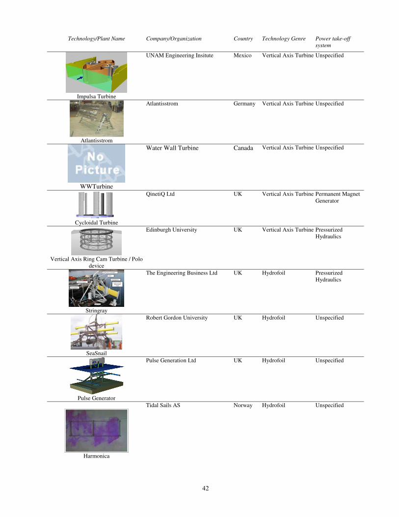
42
Technology/Plant Name Company/Organization Country Technology Genre Power take-off
system
Impulsa Turbine
UNAM Engineering Insitute Mexico Vertical Axis Turbine Unspecified
Atlantisstrom
Atlantisstrom Germany Vertical Axis Turbine Unspecified
WWTurbine
Water Wall Turbine Canada Vertical Axis Turbine Unspecified
Cycloidal Turbine
QinetiQ Ltd UK Vertical Axis Turbine Permanent Magnet Generator
Vertical Axis Ring Cam Turbine / Polo
device
Edinburgh University UK Vertical Axis Turbine Pressurized Hydraulics
Stringray
The Engineering Business Ltd UK Hydrofoil Pressurized Hydraulics
SeaSnail
Robert Gordon University UK Hydrofoil Unspecified
Pulse Generator
Pulse Generation Ltd UK Hydrofoil Unspecified
Harmonica
Tidal Sails AS Norway Hydrofoil Unspecified

43
Technology/Plant Name Company/Organization Country Technology Genre Power take-off
system
bioStream
BioPower Systems Australia Hydrofoil Unspecified
HydroVenturi
HydroVenturi Ltd UK Other Tidal Unspecified
Superconducting Magentic Energy
Storage (SMES)
Neptune Systems NetherlandsOther Tidal Unspecified
Gentec Venturi
Greenheat Systems Limited UK Other Tidal Unspecified
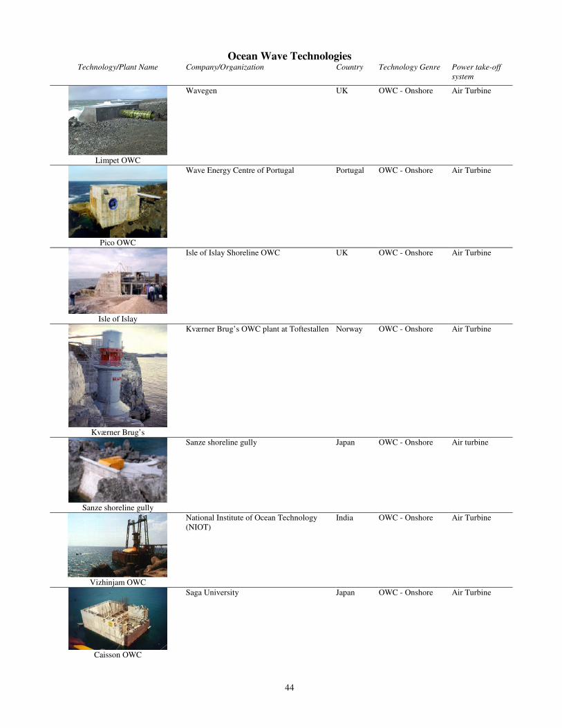
44
Ocean Wave Technologies Technology/Plant Name Company/Organization Country Technology Genre Power take-off
system
Limpet OWC
Wavegen UK OWC - Onshore Air Turbine
Pico OWC
Wave Energy Centre of Portugal Portugal OWC - Onshore Air Turbine
Isle of Islay
Isle of Islay Shoreline OWC UK OWC - Onshore
Air Turbine
Kværner Brug’s
Kværner Brug’s OWC plant at Toftestallen
Norway OWC - Onshore
Air Turbine
Sanze shoreline gully
Sanze shoreline gully
Japan OWC - Onshore
Air turbine
Vizhinjam OWC
National Institute of Ocean Technology (NIOT)
India OWC - Onshore Air Turbine
Caisson OWC
Saga University Japan OWC - Onshore Air Turbine

45
Technology/Plant Name Company/Organization Country Technology Genre Power take-off
system
Onshore OWC
Guangzhou Institue of Energy Conversion (GIEC)
China OWC – Onshore Air Turbine
Tunneled Wave Power Plant
SeWave Ltd Denmark OWC - Onshore Air Turbine
The Sakata OWC
Ministry of Transport Japan OWC - Near-shore Air Turbine
Wave Energy Conversion Actuator
(WECA)
Daedalus Informatics Ltd Greece OWC - Onshore Air Turbine
Osprey OWC
Wavegen UK OWC – Near-shore
Air Turbine
Port Kembla OWC
Oceanlinx (Energetech)
Australia OWC – Near-shore Air Turbine
Mighty Whale OWC
JAMSTEC Japan OWC – Floating Air Turbine

46
Technology/Plant Name Company/Organization Country Technology Genre Power take-off
system
Backwards Bent Duck Buoy
Guangzhou Institue of Energy Conversion (GIEC)
China OWC – Floating Air Turbine
MRC1000
Orecon UK OWC – Floating Air Turbine
SPERBOY
Embley Energy UK OWC – Floating Air Turbine
OE Buoy
Ocean Energy Ltd Ireland OWC – Floating Air Turbine
OWEL Grampus
Offshore Wave Energy Ltd (OWEL) UK OWC – Floating Air Turbine
Pneumatically Stabilized Platform
Float Inc US OWC – Floating Air Turbine
HydroAir
Marine Energy Generation Ltd (MEG) UK OWC – Floating Air Turbine

47
Technology/Plant Name Company/Organization Country Technology Genre Power take-off
system
Archimedes Wave Swing
AWS Ocean Energy UK Absorber - Point Linear Generator
Powerbuoy
Ocean Power Technologies US Absorber - Point Linear Generator
Seabased Linear Generator
Seabased AB, Uppsala University Sweden Absorber - Point Linear Generator
Permanent Magnet Linear Generator
Buoy
Oregon State University US Absorber - Point Linear Generator
Float Wave Electric Power Station (FWEPS)
Applied Technologies Company Ltd Russia Absorber - Point Linear Generator

48
Technology/Plant Name Company/Organization Country Technology Genre Power take-off
system
Trident Energy Converter
Trident Energy Limited UK Absorber - Point Linear Generator
Wavebob
Wavebob Limited, Clearpower Technology Ltd
Ireland Absorber - Point Pressurized Hydraulics
Onshore Oscillating Buoy
Guangzhou Institue of Energy Conversion (GIEC)
China Absorber - Point Pressurized Hydraulics
Danish Wave Power (DWP) Float-Pump
Danish Wave Energy Program, Ramboll Denmark Absorber - Point Pressurized Hydraulics
Swedish Hose-pump
Not specified Sweden Absorber - Point Pressurized Hydraulics
AquabuOY
Finavera (Aquaenergy) Canada Absorber - Point Pressurized Hydraulics

49
Technology/Plant Name Company/Organization Country Technology Genre Power take-off
system
Wave Energy Point Absorber
Wave Energy S.A. Greece Absorber - Point Pressurized Hydraulics
CETO Wave Pump
Seapower Pacific Australia Absorber - Point Pressurized Hydraulics
Seadog Pump
Independent Natural Resource, Inc (INRI) US Absorber - Point Pressurized Hydraulics
Burin Wave Power Pump
College of the North Atlantic Canada Absorber - Point Pressurized Hydraulics
Sloped IPS Buoy
Edinburgh University UK Absorber - Point Pressurized Hydraulics
Syncwave
Syncwave Energy Inc Canada Absorber - Point Mechanical

50
Technology/Plant Name Company/Organization Country Technology Genre Power take-off
system
Aegir Dynamo
Ocean Navitas Ltd UK Absorber - Point Mechanical
EGWaP
Able Technologies LLC US Absorber - Point Mechanical
Wave Energy Device
Wave Energy Technology - New Zealand (WET-NZ)
New Zealand
Absorber - Point Other
Searev
Fluid Mechanics Laboratory - École Centrale de Nantes
France Absorber - Point Other
FO3
Fred Olsen Ltd. Norway Absorber - Multi Point
Pressurized Hydraulics
OMI WavePump
Ocean Motion International US Absorber - Multi Point
Pressurized Hydraulics
Wave Star
Wave Star Energy Denmark Absorber - Multi Point
Pressurized Hydraulics
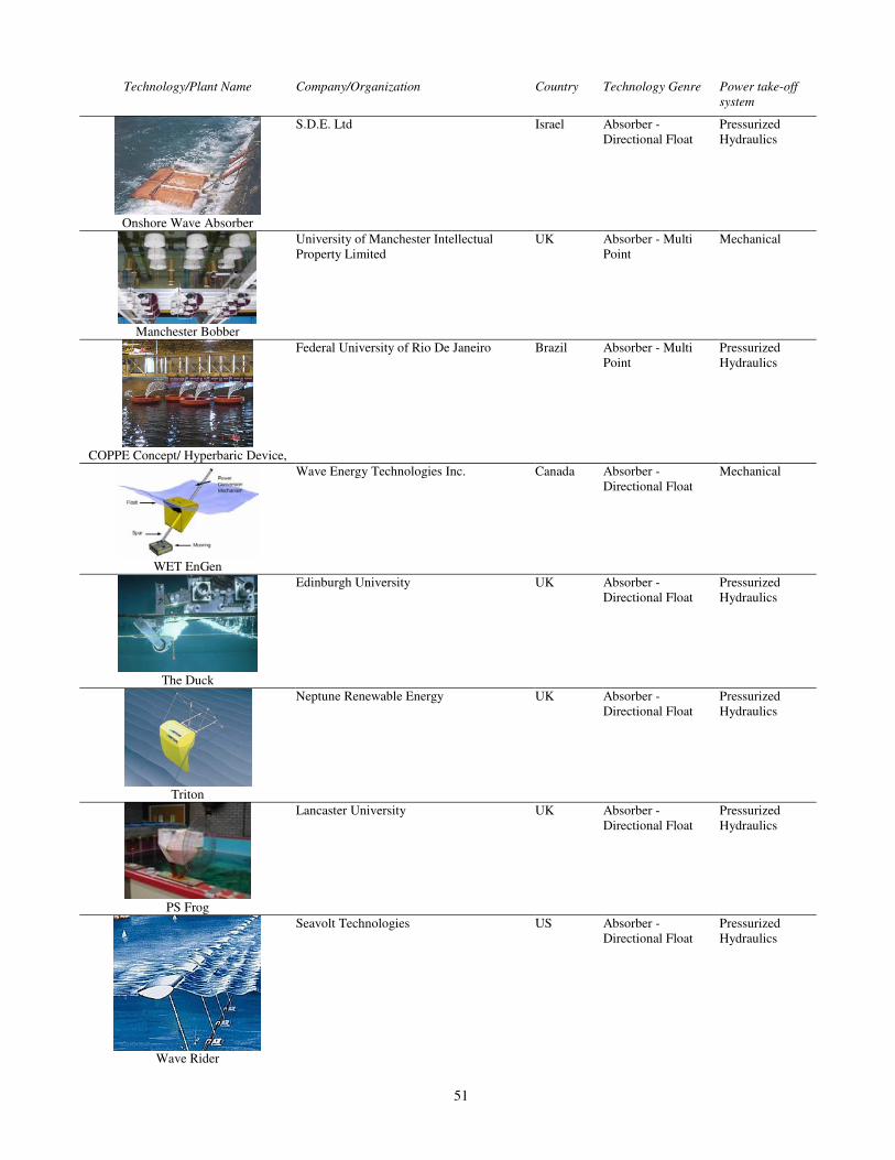
51
Technology/Plant Name Company/Organization Country Technology Genre Power take-off
system
Onshore Wave Absorber
S.D.E. Ltd Israel Absorber - Directional Float
Pressurized Hydraulics
Manchester Bobber
University of Manchester Intellectual Property Limited
UK Absorber - Multi Point
Mechanical
COPPE Concept/ Hyperbaric Device,
Federal University of Rio De Janeiro Brazil Absorber - Multi Point
Pressurized Hydraulics
WET EnGen
Wave Energy Technologies Inc. Canada Absorber - Directional Float
Mechanical
The Duck
Edinburgh University UK Absorber - Directional Float
Pressurized Hydraulics
Triton
Neptune Renewable Energy UK Absorber - Directional Float
Pressurized Hydraulics
PS Frog
Lancaster University UK Absorber - Directional Float
Pressurized Hydraulics
Wave Rider
Seavolt Technologies US Absorber - Directional Float
Pressurized Hydraulics

52
Technology/Plant Name Company/Organization Country Technology Genre Power take-off
system
Wave Dragon
Wave Dragon Ltd. Denmark Overtopping Water Turbine
TAPCHAN
Norwave A.S., Oslo Norway Overtopping Water Turbine
Seawave Slot-Cone Generator
WAVEenergy AS Norway Overtopping Water Turbine
Floating Wave Power Vessel (FWPV)
Sea Power Sweden Overtopping Water Turbine
WaveRoller
AW-Energy Oy Finland Inverted Pendulum Pressurized Hydraulics
C-Wave
C-Wave Limited UK Inverted Pendulum Pressurized Hydraulics
Frond
The Engineering Business UK Inverted Pendulum Pressurized Hydraulics
Oyster
AquaMarine Power Ltd UK Inverted Pendulum Pressurized Hydraulics
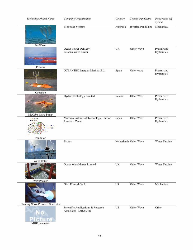
53
Technology/Plant Name Company/Organization Country Technology Genre Power take-off
system
bioWave
BioPower Systems Australia Inverted Pendulum Mechanical
Pelamis
Ocean Power Delivery; Pelamis Wave Power
UK Other Wave Pressurized Hydraulics
Oceantec
OCEANTEC Energias Marinas S.L. Spain Other wave Pressurized Hydraulics
McCabe Wave Pump
Hydam Techology Limited Ireland Other Wave Pressurized Hydraulics
Pendulor
Muroran Institute of Technology, Harbor Research Center
Japan Other Wave Pressurized Hydraulics
Wave Rotor
Ecofys Netherlands Other Wave Water Turbine
WaveMaster
Ocean WaveMaster Limited UK Other Wave Water Turbine
Floating Wave Powered Generator
Glen Edward Cook US Other Wave Mechanical
MHD generator
Scientific Applications & Research Associates (SARA), Inc
US Other Wave Other

54
Technology/Plant Name Company/Organization Country Technology Genre Power take-off
system
Ocean Wave Energy Converter (OWEC)
Ocean Wave Energy Company (OWECO) US Other Wave Linear Generator
Gyro-Gen
Aaron Goldin US Other Wave Other
WavePlane
WavePlane International AS Denmark Other Wave Water Turbine
Tetron
Joules Energy Efficiency Services Ltd UK Other Wave Pressurized Hydraulics
Waveberg
Waveberg Development Limited Canada Other Wave Pressurized Hydraulics
Wavemill
Wavemill Energy Corporation Canada Other Wave Pressurized Hydraulics
WaveBlanket
Wind Waves and Sun US Other Wave Air Turbine

55
Thermal Gradient Technologies
Technology/Plant NameCompany/Organization Country Technology Genre Power take-off
Barge-Mounted OTEC
National Institute of Ocean Technology (NIOT) India OTEC Other
Land-based OTEC
National Institute of Ocean Technology (NIOT) India OTEC Other
Closed-Cycle OTEC
NELHA US OTEC Other
Open-Cycle OTEC
NELHA US OTEC Other
Closed-Cycle OTEC
Tokyo Electric, Kyushu Electric, Saga University Japan OTEC Other
Hybrid OTEC
Saga University Japan OTEC Other
Kalina Cycle OTEC
OCEES International, Inc US OTEC Other
Hybrid OTEC
Sea Solar Power, Inc US OTEC Other
OTEC
Maine Development Associates, Inc US OTEC Other

56
Salinity Gradient and Hydrothermal Vent Technologies
Technology/Plant Name Company/Organization Country Technology Genre Power take-off system
Pressure Retarded Osmosis
Statkraft, SINTEF Norway Salinity Gradient Other
Hydrocratic Generator
Wader LLC US Salinity Gradient Other
Reverse Electro Dialysis
Westus NetherlandsSalinity Gradient Other
Hydrothermal Vent Power
UNAM Engineering InstituteMexico Hydrothermal Other

57
APPENDIX B
Brief Description of the Conversion Processes

58
B1 Tidal Barrage Technologies La Rance, France Completed in 1966, the Rance barrage is the oldest tidal power plant and the largest in terms of power output at over 240MW rated power. Average annual power output is 600GWh (68.7MW). The plant uses reversible Kaplan turbines, which can generate during just the flood or ebb tide, or during both parts of the tidal cycle. The generators can also be used as pumps in order to optimize the timing of power delivery. Although dynamic control of generation/pumping did increase the power output, it was decided that, because of the environmental impact of reduced tidal range as well as overall predictability of the power delivery, the plant would generally be run in one-way ebb generation. Given the size of the plant, its length of operation, and its integration into the commercial grid, La Rance is probably the most successful ocean power installation to date [10][35]. Annapolis, Nova Scotia Power, Canada The Annapolis river tidal generator plant has been in operation since 1984, and with a rated power output of 20MW, it is second only to the La Rance barrage. The plant operates on a unidirectional basis, generating on the ebb tide and filling the reservoir on the flood tide, giving it an average annual power production of 50GWh (5.7MW). It is based on a single, 20MW rim-generation-type Straflo turbine, which is the largest of its type in the world [33]. Sihwa Tidal Barrage, Ministry of Maritime Affairs and Fisheries (MMAF), Republic of Korea In 1994, the Korean government built a 12.7 km barrage across an estuary near Ansan, Korea, with the goal of reclaiming an area of the sea for agriculture and a freshwater reservoir. However, industrial use of the new lake combined with the low amount of freshwater recharge resulted in substantial pollution, and in 2001, holes were added to the barrage to reconnect the lake with the sea. The new plan for the site calls for the creation of a tidal barrage type generation plant, whose large amount of inflow/discharge is expected to substantially improve the water quality in lake Sihwa. Construction is now underway on 254 MW of generators for the tidal barrage, which will make the Sihwa barrage the largest tidal barrage (passing La Rance) in the world once it is completed in near future. The plant is based on one-way, ebb tide generation, allowing it to generate power twice per day. Further sites for tidal barrages in Korea are under consideration The Sihwa Tidal barrage plant is expected to start operation in 2009 [15][38]. Jiangxia, China (and other Chinese barrage plants) The Jiangxia tidal plant, built in China in 1980, provides up to 3.2 MW of power, averaging 11GWh per year (1.3 MW). Additional tidal barrage plants were constructed in Baishakou and Haishan, providing up to 640 kW and 150 kW, respectively. Detailed information about the power generation equipment at these facilities was not available [10][17][27]. Kislaya Guba, Russia In Kislaya Guba, Russia, a tidal barrage was built in 1968 to take advantage of a natural 50 m-wide channel between Ura Bay and the sea. A floating power plant was built and then towed into position, where it was sunk to close off the channel. The plant contained a reversible bulb-type turbine/generator that uses an “asynchronous synchronous generator” (possibly a synchronous generator run at variable speeds whose output is then put through power electronics to synchronize it to the grid). Unfortunately, due to the small tidal range present at the site (2.3m), the plant has a rated capacity of only 0.4MW [10] [34].

59
Offshore Tidal Lagoons, Tidal Electric, UK
Representing a new approach to tidal barrages, ‘Tidal Electric’ has developed a system based on an artificial offshore lagoon. The lagoon would be located in shallow water in an area with suitably large tidal range; a lagoon system would be created there by an encircling wall made of concrete or rock fill, and would consist of either one large lagoon or multiple smaller ones. Several reversible, low-head turbines would be used to allow generation on both flood and ebb tides, and in the case of the multiple lagoon system, keeping each reservoir at different heights during the tidal cycle could allow for continuous power generation. The Tidal Electric system does not require an estuary to be closed off, which should minimize the impact on the environment and other ocean users. The company has developed a proposal for a tidal lagoon at Swansea Bay, UK [36][37]. Tidal Delay, Woodshed Technologies Pty Ltd, Australia The Tidal Delay technology is designed for areas where an isthmus or bay has created a natural partially closed tidal barrage. In such areas, the change in the level of water in the constrained area can lag the level of the sea, leading to a head difference between the two locations. The tidal delay system uses a pipe either passing over the isthmus (using the siphon effect) or an underground pipe running between the ocean and the constrained area. In both cases, the water would be run through a bi-directional turbine to generate power. Although the technology required is already well understood, the amount of power that can be generated and the feasibility of the system depends on both the length of pipe necessary and the tidal range available at the site [39]. Two-Basin Barrage, UNAM Engineering Institute, Mexico Several sites in the Mar de Corts region (between the Baja peninsula and mainland Mexico) have been identified as possible sites for tidal barrages due to their substantial tidal range. Over 3.4 GW (28.5 TWh/y) of possible barrage power has been identified in this region. Seeking to improve the power delivery characteristics, engineers at UNAM have developed a concept for a two-basin system requiring only a small barrage. The system would take advantage of the two naturally existing basins at Puerto Peasco that drain through a narrow inlet, and could provide up to 86 MW of power [32].

60
B2 Tidal Current Technologies
B2.1 Horizontal-Axis Turbines SeaFlow and SeaGen, Marine Current Technologies, UK The SeaFlow project involved a full-scale demonstration device installed in the Bristol Channel, UK, with a rated power of 300 kW. The device consisted of a 2-bladed, 1 1m-diameter variable-pitch rotor connected through a gearbox to an induction generator. The turbine was mounted on a movable assembly, which allowed it to be raised out of the water for maintenance. The assembly was attached to a single ‘monopile’ base that was then anchored to the seafloor. The initial device was not grid-connected, however it was able to reach the targeted peak power levels of 300 kW [45][46][47]. Following the success of SeaFlow, MCT designed and built the SeaGen, a 1.2MW twin-rotor turbine similar to SeaFlow. Installation has been done in 2008 and the SeaGen grid-connected system is currently operating [5]. Verdant Power, US
Verdant Power has been exploring its horizontal axis FreeFlow turbines in the East River in New York. The seabed-anchored turbines are 5 m in diameter, three-bladed and fixed-pitch, and use a small hydrofoil to align the turbine to the tidal flows. The first turbine is operational and providing 35 kW (peak) of power to a few local businesses. Installation of additional turbines, up to the pilot plant’s 175 kW total, is in progress. The company is also investigating the creation of tidal plants up to 5 MW in various locations around the world [63][64].
Hammerfest Strom AS, Norway
The Hammerfest tidal turbine is a 3-bladed, seabed-anchored device that turns (like a wind generator) to face varying tidal flows. Although limited information on its performance is available, its is known that the device is rated at 300 kW and has been connected to the power grid for the nearby town of Hammerfest. The company also has plans to build and install a prototype in Scotland, eventually leading to 1 MW commercial devices [42][43]. Underwater Electric Kite, UEK Systems, US The Underwater Electric Kite consists of a pair of contra-rotating, ducted turbines, and uses buoyancy control to operate at varying heights within the stream. This design avoids the need to fix the device to the seabed, and allows it to move freely to the highest flow areas in the current. The UEK is designed for rivers as well as tidal streams, with the current prototype employing a pair of 3 m diameter turbines for a maximum output of 90 kW in 2.5 m/s currents. The first prototype was deployed near a hydro plant in St. Catherine, Ontario, and more tests/developments are being explored near a hydro plant in Manitoba. The company also has plans to deploy the UEK in Zambia, Columbia, and at other sites worldwide [77][78]. Clean Current, Canada The CleanCurrent tidal turbine uses a ducted configuration, with a variable-speed permanent magnet generator rated at 65 kW. The generator is a rim-type permanent magnet generator, where the ends of each turbine blade form the rotor and the surrounding cowling forms the stator. The first prototype device was installed at the research facility at Race Rocks, BC, where a combined renewable energy system incorporating the turbine, 7 kW of solar power, and a battery storage system were used for replacing diesel generation at the off-grid location. Performance data for the tidal turbine is not publicly available, however Clean Current has plans for an array of commercial tidal turbines ranging from 1.1-5.0MW [65][66][67]. Newer designs and subsequent deployments in Bay of Fundy, Nova Scotia, Canada, is expected in 2009-2010 period.
61
TidEl, SMD Hydrovision, UK The TidEl device uses a pair of fixed-pitch turbines mounted on a central boom. It is partially buoyant and anchored to the seafloor via mooring lines, allowing it to float at any depth and rotate to face any direction. The arbitrary positioning of the device allow it to be placed in the middle of a channel, avoiding problems with cavitation that can occur near the surface while also removing the need for extensive mountings to be built on the seafloor. This design also allows the device to be placed in the highest flow areas of a channel, and to be floated to the surface for performing maintenance. The full size device will use a pair of three-bladed, 15 m-diameter turbines to generate up to 1 MW of power, and will use a rectifier-inverter for providing stable output. Thus far, a 1:10 scale device has been built and tested, and development of a full-size prototype is underway [58][59][60]. Open-Centre Turbine, OpenHydro, Ireland The OpenHydro tidal turbine is an open-centre, rim-generator style tidal turbine, similar to the Clean Current Turbine, at least from the perspective of machine design. The 6 m-diameter turbine uses high solidity blades and is mounted on a twin-monopile structure that can raise and lower the turbine into/out of the water for testing and maintenance. Commercial devices would be permanently anchored to the seafloor. The prototype will be connected to the grid, however no information about the device’s performance is available. OpenHydro has purchased Florida Hydro, a company that was developing a similar open-centre turbine and which had conducted tests of a 5.6 kW prototype. OpenHydro has secured funding for a second turbine in the same location, and has plans to install a turbine in Bay of Fundy, Nova Scotia, Canada, as well [70][71][72][73]. Tocardo, Teamwork Technologies BV, The Netherlands The “Tocardo” turbine is a horizontal-axis tidal turbine that uses a two-bladed, fixed-pitch turbine. The variable-speed turbine is designed for mounting in the outflow sluices of storm protection barrages. A grid-connected prototype, with a 2.8 m diameter rotor, was deployed in 2006 and generated up to 35 kW in currents of 3.2 m/s. While the prototype employed a gearbox, future devices will instead use permanent magnet generators directly coupled to the turbines. The company has plans for further deployments of the devices, including a 100-200 MW farm of 10 devices in near future [61][62]. Evopod, Oceanflow Energy, UK A recent entry into the area of tidal turbines, the Evopod consists of a turbine and generator mounted in a pod underwater, supported by a floating platform. The hydrofoil-like shape of the platform, along with the mooring system, allows the device to face currents from any direction. The overall system attempts to use standard wind turbine equipment where possible, including a gearbox for the generator. A 1:10 scale prototype of the device was the first device tested at the New and Renewable Energy Centre (NaREC) tidal test center, and the company is developing a 500 kW prototype, which it plans to install at the European Marine Energy Center (EMEC) test facility in Orkney, UK [40][41]. Scotrenewables Tidal Turbine (SRTT), Scotrenewables, UK The SRTT consists of a floating pontoon, which is held in place by a mooring cable and connected to a seafloor-mounted electrical junction box by a separate, floating cable. Two nacelles hang down on either side of the pontoon, each holding one of the two contra-rotating turbines. The nacelles are designed to fold up towards the pontoon during transportation. Sea trials of a 1:7 scale prototype have begun, and further survivability tests using scale models are planned [44].

62
Swan Turbine, Swanturbines, UK The Swan Turbine is a horizontal-axis tidal turbine with a novel maintenance system. The turbine is mounted on the seabed, and uses fixed-pitch blades and a low-speed generator in order to remove the need for a gearbox and minimize the amount of moving parts required. The turbine mounting is designed to telescope, so that the turbine can be raised up out of the water for installation, maintenance, and removal. The company has tested a 1.5 kW prototype, and development work for a medium-scale, 350 kW turbine is in progress [53]. Rotech Tidal Turbine (RTT), Lunar Energy, UK
The RTT is a horizontal axis turbine that uses a duct to direct and accelerate the flow of marine currents. The flared opening of the duct straightens the incoming flow, allowing the device to effectively generate energy from currents that are 30 or more off-axis. It uses fixed-pitch turbine blades and an unconventional hydraulic power take-off system; the turbine is used to power a hydraulic motor whose pressurized output is then directed to a generator module above. The RTT uses a gravity base to anchor itself to the seabed, and it is designed so that the whole center section (containing the turbine and generator) can be removed when performing maintenance. Small-scale laboratory tests have been completed, and the company has plans to install a 1 MW unit at the Orkney test facility. Lunar Energy has obtained an investigative use permit for the Discovery Passage, BC area, and it plans to begin development work for that area in 2009 [18][74][75]. Semi-Submersible Turbine (SST), TidalStream, UK
TidalStream has developed the SST design with the aim of deploying units in the Pentland Firth, UK, a high-energy tidal site. The device is buoyant, and consists of a vertical boom on which four turbines, in two contra-rotating pairs, are mounted. The boom is rigidly attached to an anchored base on the seabed, but it is allowed to swivel around the joint both vertically and horizontally. The movement of the joint allows the device to be floated to the surface during installation, maintenance, and removal, reducing the amount of work that must be performed underwater. During normal operation, it floats with only the very top of the device above the water. A small-scale demonstrator for the turbine and buoyancy technology was deployed in the Thames River; although the prototype was connected to the grid, due to the low power of the turbine and the static losses of the generation equipment, no power could be delivered [48][49].
Marenergie, Pole Mer Bretagne, France The Marenergie project was developed by a working group of companies known as Pole Mer Bretagne. The device itself is a seabed-anchored horizontal-axis ducted tidal turbine. The duct for the turbine is hexagonal in shape, making it robust and simple to manufacture. Small-scale tank tests have been performed, and the group is developing a 200 kW prototype device that will eventually lead to full-scale,1 MW devices [69]. Tidal Stream Generator (DeltaStream), Tidal Hydraulic Generators Ltd (THGL), UK THGL has developed a tidal turbine system designed for implementation in ecologically sensitive areas. The system is based on an array of turbines that rests on the seabed, and aside from the mass of the device, no additional anchoring systems are used. The turbines are used to pump a hydraulic fluid (vegetable oil) onshore, where it is used for power generation. The company also has a design that can pump seawater for desalination. A series of tests with a 6 m-diameter turbine were conducted in Milford Haven Waterway, UK, and the company has plans for 3.5 MW plant to be located in Pembrokeshire, UK. In 2006, THGL and the engineering company “Peter Brotherhood” partnered to create a new company, Marine Energy Generation Ltd (MEG). MEG will build on the THGL developments to create the DeltaStream, a 1 MW device based around three turbines mounted on a triangular base. The company has plans to build a full size device in near future, but no information on its progress is available [56][57][119].

63
TidalStar, Bourne Energy, US
The TidalStar is a floating tidal turbine rated at 50 kW. The turbine uses a pair of contra-rotating blades, one in front of the other, mounted in a pod attached to a floating pontoon. The complete system would involve a series of pontoons/turbines, each connected to another, reaching across a tidal channel. Further details about the system are unclear, but the company is currently developing 1:3 and 1:7 scale prototypes [54][55]. Hydrokinetic Generator, Kinetic Energy Systems, US The Hydrokinetic generator is based on a large, rectangular duct that narrows down toward the back, where the water passes through the generator. No particular turbine/generator is specified, however the company believes that it can support turbines ranging from 5 kW to 4.5 MW. The duct is designed for incorporation into a larger platform, which would also support an offshore turbine to allow for combined power generation [68]. Statkraft Tidal Turbine, Statkraft, Norway The Statkraft tidal turbine is based on a floating platform anchored in a tidal channel. A pod hangs down into the stream from each side of the platform, with two turbines mounted on each pod. Both turbines are connected to the same generator, with one rotating the rotor and the other rotating the stator in the opposite direction. The contra-rotating arranged reduces the torque on the supporting arms, and doubles the effective speed of rotation of the generator. Each generator is rated at 500kW, giving the full device a rating of 1 MW. The company is developing a prototype plant, called MORILD, and they are planning to complete it in near future [50][51]. Submerged Tidal Turbine, Tidal Generation Limited (TGL), UK TGL is currently developing a submerged, horizontal-axis tidal turbine. The information available is limited, but the device appears to be seabed-anchored with a three-bladed, fixed-pitch turbine. It is designed for operation in depths of more than 30 m, where there are significant tidal resources. Currently, the company is working on a 500 kW prototype turbine, which it plans to install at the Orkney test centre [52]. B2.2 Vertical Axis Turbines
Gorlov Helical Turbine, GCK Technology, US The Gorlov turbine is a vertical axis turbine, which uses blades that are twisted into a helix shape, rather than the straight blades typically employed by other vertical axis turbines. The helical shape reduces the amount of vibrations that can otherwise occur in vertical turbines and allows the turbine to capture up to 35% of the energy of the water flowing through it. Extensive prototype tests have occurred, including a test in Amesbury, Massachusetts that was performed in 2004 in partnership with Verdant Power. During the test, a small turbine generated up to 0.8kW in currents of 1.5 m/s. Testing has also occurred in South Korea, where in 2002 a pair of turbines were deployed in Uldomok Strait. Following the successful tests, the Korean Ocean R&D Institute began work on a 1 MW plant based on a larger turbine and a pair of generators. GCK Technology has also deployed small turbines in Maine, New York, and Brazil. The turbine in Maine generates up to 5 kW and is grid-connected, and the one in Brazil is used to provide power for a remote community [15][17][89][88][90].
Enermar Kobold Turbine, Ponte Di Archimede International S.p.A., Italy The Kobold Turbine is a vertical axis turbine suspended from a floating buoy. The prototype, installed in the Strait of Messina, Italy, uses three blades with a 6 m-diameter turbine, generating up to 25 kW from currents of 2.0 m/s. The turbine has been operating since 2001, and since 2005 has been supplying power to the local grid. A rectifier-inverter is used to provide a stable electrical output, and the overall turbine and power system

64
have been enhanced with a fully automatic control system. Further development is occurring towards an improved device, and projects to provide power to island nations are under investigation [84][85].
Wanxiang Vertical Turbines, China Two significant tidal turbine prototypes have been created in China. The Wanxiang-1, with a 70 kW capacity, consisted of two vertical axis turbines mounted on a small floating barge. Operational for several years, the barge produced between 5-20 kW of power in 2-2.5 m/s currents. The Wanxiang-2 uses gravity-based anchoring to sit on the seabed, with the generators and electronics mounted above the waterline. It employs two vertical axis turbines, and has a rated capacity of 40 kW. No performance data is available for the second device [27].
Davis Hydro Turbine, Blue Energy, Canada
The Davis Hydro turbine is vertical axis turbine designed for use in tidal currents. The design was pioneered by Barry Davis, who worked with the NRC to develop a series of grid-connected prototypes, the latest of which became operational in 1987. The prototypes ranged from 4-100 kW, including a device that generated up to 70 kW for the Nova Scotia power grid. Blue Energy has a concept design that uses a string of devices to form a “tidal fence”, a tidal barrage-like structure made up of a wall of turbine units mounted across a tidal estuary [80][81]. EnCurrent Turbine, New Energy Corporation Inc., Canada Much like Blue Energy, EnCurrent drew from the similar early designs and prototypes that were created by Barry Davis. The company has demonstrated its technology in freshwater applications (rivers, hydro dams & industrial outflow channels) and has plans to develop a 500 kW demonstration project at Canoe Pass, BC, which could later be expanded further up to 7 MW [82][83]. EXIM Tidal Turbine, Sea Power, Sweden The EXIM turbine is vertical axis turbine designed for a per-unit power output of up to 72 kW. A small prototype was deployed in the Shetland Islands, UK, where it was mounted on a boat for tests at controlled speeds. The prototype generated 2 kW with currents of 2 m/s, and 3 kW with currents of 2.5 m/s. There were plans for a full-scale demonstration device to be built in 2004, however no information about its progress is available [86][87]. Proteus, Neptune Renewable Energy Ltd, UK Designed for quick mooring, the Neptune Proteus is a floating, vertical-axis tidal turbine. The turbine is mounted underneath a barge, where hinged plates form a variable shape duct that directs the flow of water through the turbine. A gearbox and generator are mounted on top of the barge, where they can be easily serviced. A 1:100 scale model of the turbine has been tested, and development of a 1:10 scale prototype is in progress [91]. Impulsa Turbine, UNAM Engineering Institute, Mexico The Impulsa design is based on a pair of vertical axis turbines mounted on a floating platform. Each turbine is contained in a specially shaped channel that directs water flows around and into the turbine, maximizing the amount of tidal current energy available to the turbine. Small-scale tank tests of the shaped channels have been performed, and the group estimates that a 24m2 set of turbines could generate up to 194 kW in 3 m/s currents [32].

65
Atlantisstrom, Germany The Atlantisstrom uses a variable blade pitch turbine, much like vertical axis turbines; however, it is mounted with its axis of rotation across the channel. The mounting system allows the turbine to be mounted between two pilings or bridge supports, or supported by cabling from each bank of a narrow channel. The variable pitch blades turn face-on to the flow on the retreating side of the turbine, and are aligned into the flow, for minimum drag, on the advancing side. This design allows the turbine to self-start. The company has built and tested a 1:10 scale model of the turbine concept, and is currently seeking funding for a full-scale device. They estimate that the full sized 10 m-diameter turbine could produce around 100 kW in flows of 3 m/s [93]. Water Wall Turbine, Water Wall Turbine Inc., Canada
Water Wall turbines are being designed and researched with a view to achieving environmentally friendly and economic operation. While information on these systems’ performance and operational aspects is not available, the company aims at harvesting 200 MW of Renewable Energy by 2012 and aims at larger multi-unit projects [94]. Cycloidal Turbine, QinetiQ Ltd, UK
QinetiQ undertook an extensive process of mathematical modeling to develop a concept design for a vertical-axis turbine. The turbine would use 3 or 6 variable-pitch blades attached to a central hub, and depending on the design used, could generate between 62 kW and 110 kW of power (daily average). The turbine would use a permanent magnet generator, with the rotor and stator split between the turbine hub and base to allow maintenance to be performed on each part independently [79]. Vertical Axis Ring-Cam Turbine, University of Edinburgh Wave Power Group, UK The Vertical Axis Ring-Cam Turbine uses an unconventional power take-off system based on hydraulics. The buoy itself consists of a ring-shaped floating section (fixed by mooring lines) that supports the rim of a vertical axis turbine. A set of ring-cam pumps is connected to the rim of the turbine and sheltered inside the float; the float itself has a series of indentations where the turbine joins it. As the turbine turns, the ring-cam pumps pass by each indentation, driving down a piston and pumping hydraulic fluid. The fluid can then be used to power a hydraulic motor and generator. The design does not require the turbine to have a central shaft, potentially making large designs more feasible. Thus far, no prototype testing of the design has taken place [95].
B2.3 Hydrofoil Systems Stingray, The Engineering Business Ltd, UK
The Stingray is somewhat unusual design that uses a variable-pitch oscillating hydrofoil to generate power from tidal currents. The hydrofoil is attached by an arm to the fixed seabed-anchored base, which allows the hydrofoil to move vertically. Water flowing over the hydrofoil generates lift, and the varying angle of attack of the hydrofoil causes it to rise and fall in the water, pumping hydraulic fluid. This hydraulic fluid can be directed to a motor for power take-off. The prototype was rated at 150 kW of power; averaging 40-50 kW of hydraulic power in 2 m/s flows (electrical power levels would be somewhat lower). According to an EPRI report, the company is no longer developing the Stingray technology [73][103][104]. Pulse Generator, Pulse Generation Ltd, UK Pulse Generation Ltd. is developing a tidal current generator that uses oscillating hydrofoils to extract energy. The device will be anchored to the seabed in a shallow water environment, with the generation gear mounted in a module above the water. Two hydrofoils, one on each side of the device, oscillate up and down as the tidal current flows past them, driving a rod and cam system that converts the motion into rotation. This

66
mechanical drive system is then directly connected to a permanent magnet generator. The company claims that many hydrofoils can be connected to a single generator. The hydrofoils are designed to have a variable stroke width, so that as the water depth increases during the tidal cycle, the device can harness the full depth of the channel. Small-scale tank tests have been completed, and the company is developing a 100 kW, grid-connected prototype that it plans to install in near future [102]. Harmonica, Tidal Sails AS, Norway Tidal Sails AS has designed an unconventional tidal current system based on a series of stacked sails. The Harmonica consists of a large stack of rectangular sails, held together by cables in each corner. As the tidal current begins to flow, the square sails are released one by one, pulling the cables along and turning a generator. When the tidal current reverses, the sails are sent back, generating power on the return cycle as well. Tank tests of the system have been completed, and the installation of a 25 m long prototype is planned [98][99]. B2.4 Other Tidal Systems Venturi-Turbine, Coastal Hydropower Corporation, Canada The Coastal Hydropower Corporation has developed a hybrid tidal turbine design that involves both a venturi and a vertical-axis turbine. The vertical-axis turbine is placed at the center of a venture duct, which accelerates the flow of water and directs it towards the turbine. The company is currently investigating the use of both straight-bladed and helical-bladed turbines. The turbine and venturi have undergone small-scale testing using a towed platform at sea; however, it does not appear that these tests incorporated power take-off [92]. bioStream, BioPower Systems, Australia The bioStream tidal current generator is based on the oscillations of a variable angle hydrofoil, and is somewhat like a vertical-hydrofoil version of the Stingray. The hydrofoil, whose shape is based on that of a shark’s tail, varies its angle of yaw in order to rotate around a seabed-anchored column that contains the generation equipment. Power take-off is accomplished using a system of gears and a flywheel connected to generator. Scale prototypes are under development, but no information on their progress is currently available [96]. Hydroventuri, HydroVenturi Ltd, UK The Hydroventuri system takes advantage of the venturi effect. It accelerates water through a narrow opening, decreasing the pressure and pulling water from the surface into the chamber. This movement of water is then used to power an onshore turbine. The Hydroventuri system thus has no moving parts underwater, reducing maintenance and environmental impact. A 150 kW prototype is installed and operating in Grimsby, UK, however data about its performance is not available. Hydroventuri is currently working with the San Francisco government to develop plans for larger tidal power systems for San Francisco bay [76][100][101]. Superconducting Magnetic Energy Storage (SMES), Neptune Systems, The Netherlands
Neptune Systems’ concept design for SMES uses magnetohydrodynamics to extract energy from marine currents. The design calls for a cryogenically cooled, superconducting DC coil electromagnet to be mounted on the seabed, where passing tidal currents would be used to generate power. The company also has designs for extracting energy from waves and for storing energy offshore [105].

67
Gentec Venturi, Greenheat System Limited, UK The Gentec Venturi uses a multistage system in an attempt to generate continuous power. The system uses floating venturi ducts to generate electricity, which is then use to heat water in the storage system. The water is then boiled to make steam, which is then run through turbines to generate electrical power. Greenheat Systems Limited claim that the multistage system will be able to generate a constant amount of power suitable for base load, and that the losses due to the extra conversion do not stop the overall system from being economic. No demonstrations showing the viability of such a system have been conducted [97]. B3 Ocean Wave Technologies B3.1 OWC (Oscillating Water Column) Systems
• OWC – Onshore
Limpet OWC, Wavegen, UK
The Limpet 500 is a grid-connected, shoreline-based OWC, with a rated power of 500 kW. The Limpet used a unique construction method, where construction of the concrete column structure occurred behind a rock wall, which was then removed using explosives. Unfortunately, several complications arose due to the presence of debris near and underneath the structure, and the overall performance of the device was found to be highly dependent on the shape and depth of the seafloor around the device. The OWC drives a pair of Wells turbines, and provides around 22 kW of power (annual average), peaking near 150 kW. Although there were plans to use varying rotor resistance in the induction generators in order to control the power level and deliver power directly to the grid, the final system used a rectifier-inverter to stabilize the output [106][107]. Pico Power Plant, Wave Energy Centre, Azores, Portugal An OWC power plant, rated at 400 kW, was installed on the shoreline of the island of Pico, in the Azores. The plant uses a concrete structure, mounted on the seabed/shoreline, with a Wells turbine used for power take-off. Originally built in 1995-1999, various problems caused testing of the prototype to stop. Testing resumed in 2005, with much of the original equipment still intact (notably, the generator and turbine), and the plant was connected to the local power grid. Unfortunately, the presence of mechanical resonance in the structure prevented the plant from operating at optimum power levels, limiting it to power production in the 20-70 kW range. Efforts to improve the plant are ongoing [108][109]. Kværner Brug’s , Toftesfallen OWC, Norway In 1985, a 500 kW-rated shoreline OWC device was installed in Toftesfallen, Norway. The device consisted of a large steel cylinder that was anchored to a cliff above the ocean. In 1988, during a storm, the anchoring gave way and the device sank [110]. Vizhinjam OWC, India
The Vizhinjam OWC is built around a concrete caisson, which was installed a short distance from a pre-existing breakwater structure. The prototype uses a Wells turbine installed vertically above the column, which is directly coupled to an 110 kW induction generator and into the grid. The output was highly variable, from 0-60 kW in only a few seconds, and the induction generator frequently had a net consumption of power. Improvements were made to the power system, including the use of a pair of turbines to power the generator; these allowed the device to have more flexibility in adapting to the varying wave conditions. The improved design produced up to 10 kW of average power, and research into improved power systems continues [32].

68
Saga University, Japan A caisson type OWC, consisting of a vertical column with openings underwater on the wave-incident side, was installed in the Sea of Japan. The prototype used a pair of 60 kW-rated Wells Turbines. Another style of OWC, a “Constant Pressure Manifold Device”, was in operation from 1988-1997. The device used a set of OWCs, each with a one-way valve feeding into a common air reserve, from which a 30 kW generator was powered. A final type, the “Water Valve Rectifier”, had a pair of rotors connected to a single, 130 kW generator. Air was directed alternately to each turbine on the rise/fall of the water column, allowing each rotor to spin in a constant direction. In 2005, another OWC device based on a “Setoguchi” impulse turbine began operation [67][112].
Guangzhou Institute of Energy Conversion (GIEC), China Several OWC designs have been investigated by the GIEC. Beginning in 1985, a series of concrete, shoreline anchored water columns were constructed. The first was rated at 3 kW (1kW maximum average) and was followed by another 20 kW (8 kW average) prototype. Beginning in 1995, another OWC, with a rated power of 100 kW (15 kW average) was built, however, like the previous prototypes, it suffered from an unstable power output. A floating, 5 kW offshore style OWC, in the form of a “Backwards Bent Duck Buoy”, was also tried, which produced a sustained maximum of around 1 kW [27]. Tunneled Wave Power Plant, SeWave Ltd, Faroe Islands (Denmark) SeWave, in cooperation with Wavegen, have developed a novel approach to shoreline OWCs. The system is based on blasting a series of tunnels in a shoreline cliff, which are eventually linked to form a water column. Power take-off will be accomplished using a standard air turbine system. Although significant complications during the blasting are possible, the company believes that the design represents a feasible method of implementing wave power in the Faroe Islands. Several suitable sites have been located, and the company has already completed basic design work and scale model testing [111].
Wave Energy Conversion Actuator (WECA), Daedalus Informatics Ltd, Greece Daedalus Informatics has designed an OWC-based device designed for mounting on existing structures onshore and offshore. The device uses a wedge shape to direct incoming waves into the interior chamber, where the concentrated waves generate air pressure that is then stored in an accumulator. The full size device, with a height of 6m and a width of 7m, should be able to generate 20 kW at full size. It does not appear that any scale model testing has been done [114]. • OWC – Near-shore
Osprey, Wavegen, UK The Osprey was a 2 MW-rated prototype intended for the nearshore environment. The large steel structure was designed to be towed and sunk into position, and to support the addition of a wind turbine. The OWC was connected to a pair of airshafts, each containing a pair of 500 kW generators connected to Wells Turbines. Unfortunately, during the installation process, intense waves struck the Osprey before it had been secured via the addition of sand ballast, resulting in its destruction. Designs for another device were made, however, no further deployments took place [12][115]. Port Kembla OWC, Oceanlinx (Energetech), Australia The Oceanlinx OWC system is a nearshore system that can be operated either floating or fixed to the seabed/shoreline. The system uses a Denniss-Auld turbine, which incorporates variable pitch blades that adjust to each incoming wave. The generator is an induction type and uses rectification and power electronics

69
to provide a clean power supply and a limited amount of reactive power generation. A prototype was deployed in Port Kembla, Australia, and operated in a floating mode in small seas. The prototype produced up to 7 kW with small waves, implying a limit of about 500 kW with larger waves. The company has contracts and commitments to develop several large plants (up to 15 MW) worldwide [116]. The Sakata OWC, Japan
The OWC plant was incorporated into a breakwater at the port of Sakata, Japan, in 1991.The construction was sponsored by the Ministry of Transport of Japan (1st District Port Construction Bureau). The plant was equipped with a twin-rotor Wells turbine (horizontal axis, diameter 1.337m) driving a 60 kW electrical generator [113]. • OWC – Floating Kaimei “Mighty Whale”, JAMSTEC, Japan The Mighty Whale was a ship-based offshore OWC prototype deployed in Gokasho Bay, Japan. The prototype used vertical columns in the front of the ship, which fed into Wells Turbines with a total generating capacity of 110 kW. The seas in the area were relatively calm, with significant wave heights of only 0.5 m, leading to a power output of 6-7 kW (annual average). Deployment of the first device ended in 2002 [117][118]. MRC1000, Orecon, UK The Orecon MRC1000 is based on a floating buoy using the OWC principle. Rather than use a single column tuned only to one wave frequency, the MRC1000 design uses six, each tuned to a different range of frequencies. All six columns are connected to a single air turbine. Rather than drive a generator directly, the air turbine would power a hydraulic system, which would provide an energy buffer to smooth the device’s power output. Various small-scale trials have been performed, and Orecon have plans for a 1 MW device to be built and installed in the WaveHub test centre in the UK. Both the MRC1000 and the SPERBOY appear to be spin-offs of the same university of Plymouth research project [120][121][122]. SPERBOY, Embley Energy, UK The SPERBOY is a floating OWC device that uses multiple columns of different length, each tuned to a different wave frequency. A 1:10 scale prototype was built by a team from the University of Plymouth and deployed in Plymouth Sound, UK. The prototype generated about 10 kW in varying wave conditions, although unfortunately, the type of mooring used in the prototype resulted in its destruction during a storm. Studies are underway investigating a concrete version of the Sperboy. Both the MRC1000 and the SPERBOY appear to be spin-offs of the same university of Plymouth research project [23][126]. OE Buoy, Ocean Energy Ltd, Ireland The OE Buoy is a floating OWC system based on a vertical column with a horizontal water intake, a configuration called the ”backward bent duck buoy”. A large, quarter scale prototype was deployed near Galway, Ireland, however no data on its performance was available. Following successful testing of the prototype, the company has plans for a full scale, 1 MW device [123][124]. OWEL Grampus, Ocean Wave Energy Limited (OWEL), UK
The OWEL“Grampus” makes use of an OWC, but rather than using a vertical column, the Grampus uses a horizontal one. Waves travel down a tapering, enclosed box, pushing forward a trapped column of air. The air is eventually driven through a vent near the top of the device, where it is collected in a reservoir, while the

70
water is directed downwards. The Grampus is designed to be deployed in a floating configuration, with multiple columns mounted side-by-side in a fan configuration. A 15 m long, 1:10 scale prototype has been built, which demonstrated 50% wave to compressed air conversion efficiency. OWEL is currently developing a three-quarter scale, 750 kW device [123] [125]. Pneumatically Stabilized Platform (PSP), Float Incorporated, US
The PSP uses water columns to provide stabilization for a floating platform. The platform is composed of many vertical tubes, each one forming an OWC, on top of which structures (for example, natural gas drilling and liquefaction equipment) can be placed. Each column is connected by an air tube (containing a turbine) to several other water columns, and as a wave passes by, the water levels in the columns will change, driving air between the columns and through the turbines. Since the OWCs extract the wave energy, the waves are quickly reduced in size as they pass under the platform, giving it a high degree of stability. Small-scale tests of the platform concept have been conducted, however no demonstrations of its power generation capability have been performed [127]. HydroAir, Marine Energy Generation (MEG) Ltd, UK The HydroAir is a 400 kW OWC unit under design by MEG. No details about its operational environment or construction are available, but the company’s efforts are apparently concentrated on improvements to the air turbine. The company plans to build a full-scale test system in 2008 [119]. B3.2 Absorber Systems
• Point Absorber
Archimedes Wave Swing, AWS Ocean Energy, UK The Archimedes wave swing consists of a buoyant chamber, floating underwater and anchored to the seabed. As waves pass overhead, the chamber’s buoyancy changes, causing it to oscillate up and down with the waves. The prototype, installed off the coast of Portugal, is rated at 2 MW, and power takeoff is accomplished using a linear, permanent-magnet generator. During the short testing period, the prototype, which was operated from a floating pontoon, reached a peak power level of 1 MW while running at less than full capacity. Work on a next generation device for the Portuguese company Enersis is in progress, and the company is planning deployment of the device at the EMEC testing facility in Orkney, Scotland [129][130][131]. The first prototype rated 2 MW was developed by a Dutch company AWS and was tested in Portugal. Its development had started in mid-1990s. The second-generation prototype is being developed by AWS Ocean Energy UK. Powerbuoy, Ocean Power Technologies, US The Powerbuoy is a floating point absorber buoy, based on the relative movement between the inner and outer parts of a two-part buoy. The outer part of the buoy has the form of a horizontal ring whose shape and buoyancy cause it to stay near the water’s surface and oscillate with the waves. The inner part of the buoy consists of a vertical tube containing a compressible volume of air. Incoming waves will compress the air pocket, causing the inner part to move downwards as a wave crest approaches. The two parts of the buoy thus oscillate out of phase with one another. Details on the power take-off system are not available, however the patent for the device describes possible systems based on a linear generator or pressurized hydraulics. Two of the 40 kW-rated test units have been installed, one in Hawaii, and one in New Jersey, and OPT is developing plans for a 1.25 MW wave farm in Spain [141][142][143].
71
Linear Generator, Seabased AB, Sweden The Seabased system is based around a floating buoy anchored to a generator mounted on the seabed. As the buoy oscillates up and down with the waves, it pulls up and down on the connecting line, moving the piston of a linear generator. The generator is based on permanent magnets, and should produce between 10-100 kW depending on the local wave climate. A project run by Uppsala University has been working towards the development of a full wave farm at Islandsberg, Sweden. In 2006, a single 10 kW linear generator was deployed along with a group of environmental test buoys. The eventual target is for a farm consisting of 40 test buoys and 10 generators, to be completed in near future [133]. Permanent Magnet Linear Generator Buoy, Oregon State University (OSU), US Several direct-drive point absorber buoys are under development by the wave energy team at OSU. The designs involve floating, offshore buoys, either self-reacting (against an internal mass) or using taught mooring lines anchored to the seabed. In several designs, the motions of the buoy directly power a permanent magnet linear generator; in another, a rack and pinion system converts the linear movement into rotary movement that then powers a generator. The group has designs for an offshore wave park, where the outputs of several buoys would be combined and rectified to DC in an undersea junction box before being sent to an onshore inverter for further distribution. Wave-tank tests of small prototype buoys have been performed, and a large rig for demonstrating and testing linear generators is under development. The group is investigating an area near Reedsport, Oregon for potential deployment of prototype devices [25][135][136][137]. Float Wave Electric Power Station (FWEPS), Applied Technologies Company Ltd, Russia Available details about the FWEPS are limited, but the basic design of the device is a floating point absorber buoy that can be anchored in groups offshore. The device seems to use a spring-loaded internal mass, which reacts against the motions of the buoy to drive a piston through a linear generator. Each device us rated at up to 50kW. The company has performed wave-tank tests on small-scale models of the buoy, and they have designed a prototype that is now under construction [132]. Trident Energy Converter, Trident Energy Limited, UK The Trident Energy Converter is a point absorber device based on buoy suspended from a seabed-anchored platform. The vertical oscillations of the buoy drive the piston of a linear generator, generating electricity directly from the buoy’s motions. During storm conditions, the generator can be used to lift the buoy into a protective chamber. A 1:5 scale prototype has been tested, and based on its performance, the company expects that a full size unit will be able to generate about 100 kW [137]. Wavebob, Wavebob Ltd, Ireland The Wavebob is a point absorber in the form of a floating, offshore buoy. While limited details about its functionality are available, it appears to use a two-part buoy; the first part oscillates with the waves against the second part, which is damped against the movement. The Wavebob design incorporates the ability to tune the oscillating buoy for different wave conditions, allowing it to efficiently extract energy across a wider range of wave conditions than other systems can. Power take-off is accomplished via a hydraulic system. A 1:4 scale device was deployed and tested in Galway Bay, Ireland during 2006 [67][166][167]. Onshore Oscillating Buoy, Guangzhou Institute of Energy Conversion (GIEC), China The GIEC onshore oscillating buoy is a floating buoy positioned next to the shoreline and supported by a shoreline structure. Power take-off is accomplished via hydraulic pumps, and the presence of a 10 MJ energy buffer (a large hydraulic reservoir) allowed the system to provide a relatively stable power output. The 400 kW rated buoy can provide up to 50 kW of sustained power, or 4.2 L/s of desalinated water [27].

72
Danish Wave Power Float-Pump, Danish Wave Energy Program, Denmark Various point-absorber buoys based on the “Float-pump” design have been built as part of the Danish Wave Energy Program. All of them have been based on a floating buoy that is connected by a taught mooring line to a generator assembly on the seabed. As the buoy moves up and down in the waves, it pulls the mooring line and drives a hydraulic piston. A 1kW prototype was installed near Hanstholm, Denmark; the device incorporated an air reservoir which was used to buffer the energy output of the device. In 1989, with the cooperation of the Rambll company, a larger, 45 kW prototype was built. This was followed by a series of smaller floating buoy prototypes, on which development continued through 2001. Current development efforts in Denmark have now moved towards other devices [12][156][157]. Aquabuoy (IPS Buoy and Swedish Hose Pump), Finavera, Canada The IPS buoy is a floating buoy that uses reaction of a piston against a column of water to power a hydraulic power take-off system. The device underwent a sea-trial, however no data on its performance is available. The IPS buoy had been the focus of significant R&D around 1982. It was developed in Sweden by the company IPS (Interservice Project SA). Another device, known as the “Swedish Hose Pump”, also underwent sea trials. The Hose pump uses the vertical motion of a buoy to contract and expand a flexible tube, effectively allowing seawater to be pumped through the tube. The Aquabuoy is a much more recent device and was developed by the company Aquaenergy, later acquired by Finavera. A prototype of Aquabuoy (about half-scale) was tested off the coast of Oregon, USA, in 2007. This device uses reaction against a piston in a water column to alternately contract and expand two hose pumps. The Aquabuoy is rated at 250 kW, and expected to produce an average of 63 kW in a 33 kW/m wave environment. The power take-off system will involve a variable-speed generator connected to the grid via a rectifier-inverter. The company is currently seeking approval for a plant in Makah Bay, Washington, and a full-scale prototype of the Aquabuoy is currently being developed/tested [122][148][149][150][151]. Wave Energy Point Absorber, Wave Energy S.A., Greece The Wave Energy Point Absorber implements the point absorber concept using a floating buoy moored in water 10-20 m deep. The taught mooring line is connected to a hydraulic piston mounted on the seabed, where the vertical movement of the buoy pulls the mooring line and piston, generating pressures of up to 20 MPa. The pressurized seawater is directed onshore, where the outputs of several devices can be collected and used for desalination or energy generation. Small prototype devices have been constructed; in a 10 kW/m wave climate, each device can generate 2-3 kW of power (using a synchronous generator) or 0.6 L/s of fresh water [61]. CETO, SeaPower Pacific, Australia
The CETO system is based on using wave power to pump high-pressure seawater onshore for use in power production or desalination. The first prototype, CETO 1, used a large diaphragm mounted underwater that responded to the waves passing overhead. The diaphragm was connected to a lever, which was further connected to a hydraulic piston, allowing the high-pressure seawater to be pumped onshore. The second design, the CETO II, relies on a floating point-absorber buoy whose vertical movement is used to move a piston and pump seawater. The company’s commercial design, CETO III, is estimated to generate up to 190 kW of power, or 13L/s of fresh water [154][155]. SEADOG Pump, Independent Natural Resources Inc. (INRI), US
The SEADOG is a point absorber based on the oscillations of an air filled buoy. As the buoy moves up and down, it moves a piston that pumps seawater with each stroke. The seawater is delivered onshore where it can be used for desalination or electrical generation. The buoy is mounted on a platform that rests on the seabed. In a recent prototype trial in Texas, a small SEADOG pump successfully pumped 45-68L of seawater per

73
minute at pressures of 329-373 kPa in waves up to 2 m. INRI have plans to build and install another SEADOG pump in a higher-energy wave location in California [162][163]. Burin Wave Pump, College of the North Atlantic, Canada The Burin Wave Pump is a point absorber type pump. A floating buoy oscillates with the waves, moving against a submerged, damped base and driving seawater through a piston. The main application is direct use of the pumped sweater for aquaculture, but desalination or power generation is also possible. Currently, the device is undergoing small-scale dockside trials [152][153]. Sloped IPS Buoy, University of Edinburgh Wave Power Group, UK The Sloped IPS Buoy is a variation on the IPS buoy that uses a sloped configuration to extract more energy from the waves. The floating buoy has a series of tubes reaching down into the water at a 45 angle, allowing it to oscillate with both the vertical and horizontal movements of the incoming waves. As in the IPS buoy, the movement of the buoy relative to a piston resting in the water column is used to power a hydraulic power take-off system. Basic wave tank tests have been performed on the design [12][162][164]. Syncwave, Syncwave Energy Inc, Canada The Syncwave system is a two-part, floating point absorber buoy. The buoy consists of an inner and an outer part, which oscillate out of phase with each other in order to produce energy. The device incorporates an active control system, which varies the buoy’s tuning as measured wave conditions change. The power take-off method is not described in detail, but the company claims to use a direct mechanical system. Variations of the system include a device designed to interconnect with generators in off-grid locations and one designed to charge a battery and deliver DC power to remote users. The company has conducted small-scale wave tank tests and has filed for an investigative use permit for an area near Tofino, BC [145][146]. Aegir Dynamo, Ocean Navitas Limited, UK Another variation on the floating buoy point absorber concept, the Aegir dynamo incorporates a direct mechanical power take-off system. The design uses a two-part buoy, with an outer part than oscillates with the waves relative to the central part, which is damped by a plate and the mooring system. No functional details are available, but Ocean Navitas claims that some form of “Direct mechanical conversion” is used. The company has performed basic wave tank tests of the device [138]. Electricity Generating Wave Pipe (EGWaP), Able Technologies L.L.C., US The EGWaP is a point absorber based on the movement of a float within a contained water column. It consists of a pipe anchored to the seabed and reaching vertically out of the water, with the mechanical system and generation equipment mounted on top. The pipe is open to the sea at the bottom, causing the water level to rise and fall as waves pass by. Inside the pipe, a buoy rests on the waters surface and is connected by a cable to a counterweight. The cable runs over a wheel, and the wheel is connected to a rectifying gear system so that as the buoy/counterweight rise and fall, the gear system drives a generator in a constant direction. Although details about the development process are limited, it does not appear that any scale model tests have been performed [139][140]. Wave Energy Device, Wave Energy Technology - New Zealand (WET-NZ) Although limited details about the operational mode of this device are available, the basic form of the device is a floating, offshore buoy. The device appears to use a pair of interlocking buoys, with an inner core that is damped by a large plate and an outer collar that oscillates with the incident waves. The power-takeoff mechanism is unclear, however, it is described as directly driving a generator. Following wave tank and numerical modeling, a scale prototype was deployed for short trials in Lyttelton Harbour, New Zealand in 2006 [147].
74
SEAREV, Ecole Centrale de Nantes, France The SEAREV is a wave-absorbing buoy similar in design to the PS Frog. The buoy oscillates with the waves, and its oscillations relative to a large internal mass are used to generate power. The exact power take-off mechanism is unclear, but it may involve the use of hydraulics. A series of mathematical simulations were used to refine the shape of the buoy, and the simulations indicated that the use of a latched control system (that would lock the mass in place during certain points of the wave cycle) would provide improved performance. The final form of the buoy is mushroom-like, with a cylindrical internal mass located in the lower section. It is unclear whether any scale model testing of the buoy design has taken place [144]. • Absorber – Multi-Point Fo3, Fred Olsen, Norway The FO3 concept involves a floating platform containing several point absorber floats. The floats oscillate in response to the waves, and power take-off is accomplished via a hydraulic piston/motor system. The design calls for extensive use of composites for reduced weight. A 1:20 scale model was constructed to test survivability and wave response, and a larger, 1:3 scale research platform was built to provide further test data. Fred Olsen Ltd estimates that the full size plant will be able to produce 2.5 MW from 6-meter waves [158][159][160].
OceanWave Energy Converter (OWEC), OceanWave Energy Research Company (OWECO), US
An alternate approach to the point absorber concept, the OWEC uses moving floats along multiple axes in order to capture wave energy. The base of the platform is an offshore buoy, which floats below the water’s surface and is damped by a plate against wave movement. A set of floats, each floating at the water’s surface, are attached to the buoy by angled arms; each arm contains a linear generator that generates power as the buoys move with the incoming waves. Wave tank tests of the buoy and bench tests of the generator have been performed, and the company has plans that involve large farms consisting of many devices [134]. OMI WavePump, Ocean Motion International, US The OMI WavePump system is based on a seabed-anchored platform similar to an oil-drilling rig. A group of buoys sits on the water’s surface underneath the device, each buoy around a pipe/telescoping sleeve mechanism. As the buoys descend during each wave trough, their downward motions drive water through the seabed-mounted sleeve pumps and back up to the platform. The pressurized seawater can then be used for either desalination or electricity/hydrogen generation via high-pressure turbines. The company has tested a 1:20 scale prototype, and has plans for larger scale devices [161]. Wave Star, Wave Star Energy, Denmark
Implementing the multiple point absorber concept, the Wave Star is designed for locations 10-20 km offshore. It consists of a long, seabed-anchored platform from which 40 small floats hang down from lever arms on either side. The vertical oscillations of each float drive a hydraulic piston; the hydraulic output of each buoy is collected and used to run a hydraulic motor for generation. All of the hydraulic and generation equipment is mounted above the waterline, and the system is able to raise the floats out of the water during storm conditions. A 5.5kW-rated, 1:10 scale prototype has been installed at Nissum Brednig, Denmark, where it has supplied power to the grid since 2006. The company is developing a 500 kW, 1:2 scale prototype, which plans to deploy in the North Sea. The full scale Wave Star is expected to have a rated capacity of 3 MW [165].

75
Manchester Bobber, University of Manchester Intellectual Property Limited (UMIP), UK The Manchester Bobber is a point absorber device that uses a direct mechanical system for power takeoff. A buoy (or group of buoys) is suspended from a floating platform by a cable that runs over a wheel and is counterweighted on the other side. The downward oscillations of the buoy cause the wheel to turn, turning a flywheel which then turns a gearbox and generator; the generator is an induction type. A clutch disconnects the flywheel during the upward motion of the buoy. UMIP has developed a 1:10 scale prototype that uses a single buoy and a 1:100 scale prototype of a multiple-buoy device is under development. They are currently seeking funding for a full-scale device [26]. COPPE Concept/ Hyperbaric Device, Federal University of Rio De Janeiro, Brazil
Capitalizing on the expertise of deepwater technology (oil & gas industry) the hyperbaric chamber concept is being explored at Federal University of Rio De Janeiro, Brazil. It simulates the sub sea environment and considers the use of conventional turbines as employed in the hydro-electric power plants. It utilizes a set of hyperbaric chambers in a controlled combination of pressure and flow rate. Small-scale models (1:10) have been investigated for wave conditions typical to Brazilian South Region [210]. • Absorber - Directional Float
WET EnGen, Wave Energy Technologies Inc., Canada
The WET EnGen is a directional absorber float with a seabed-anchored base. A long, angled spar reaches up from the base to the surface of the water, where the absorber float is moved up and down along the spar by the incoming waves. The spar is allowed to swivel so that the float can rotate to face waves from any direction. The power take-off system is described as being mechanical, however no details on its operation are available. A 20 kW-rated prototype was tested at sea in Nova Scotia, and development of larger prototypes is in progress [172]. Onshore Wave Absorber, S.D.E. Ltd, Israel The SDE Limited device is based on a float connected to the shoreline or a breakwater via a hinge and hydraulic pistons. Incoming waves cause the float to pitch up and down, driving hydraulic fluid through the pistons and into a hydraulic motor and generator. SDE produced a series of eight test units, the largest of which produced up to 40 kW during the 8-month test period. The company has received partial government funding and plans to build a 10 MW plant in Ashdod, Israel in near future [173][174]. The Duck, University of Edinburgh Wave Power Group, UK The Duck has a long history of development that begins in 1974. Although the power take-off method has evolved over time, the basic design involves a specially shaped buoy that rotates in response to the incoming waves. While the shape of the buoy allows it to effectively harvest waves from only one direction, wave-tank tests have demonstrated that the buoy can convert up to 90% of the waves’ energy into rotational movement. The complete system would involve multiple ducks, each rotating around a common “spine”. The power take-off system is based around ring-cam pumps, where, as each duck rotates around the spine, large indentations around each joint pass over a series of pistons, driving them down and pumping high-pressure hydraulic fluid. The hydraulic fluid is then run through a hydraulic motor connected to a generator in order to create power. No sea trials or demonstrations of the power take-off system have been performed [176][177].

76
Triton, Neptune Renewable Energy Ltd, UK The Neptune Triton is a 400 kW-rated wave energy device designed for the nearshore environment (depths of around 10m). One side of a buoy is attached to a steel frame anchored to the seabed while the other is left free, allowing the buoy to oscillate vertically with the incoming waves. The buoy drives a hydraulic piston that then feeds hydraulic fluid to a turbine and generator. The company is currently developing 1:10 scale prototypes in order to test the concept [91]. PS Frog, Lancaster University, UK Following early development work on a device known as the Frog, the PS Frog was developed at Lancaster University. The PS Frog is a floating, oscillating buoy that pitches in response to incoming waves. Although the shape of the device has undergone a series of revisions, the fundamental idea involves a pitching upper section rotating around the mass of the lower, ballasted section. Power take-off is accomplished using a mass that slides relative to the buoy and moves a hydraulic ram. A series of wave tank tests have been performed on the various buoy shapes [12][175]. Wave Rider, SeaVolt Technologies, US
The Wave Rider is a floating buoy that uses a pitching motion to generate power, and is somewhat similar to the Duck. The pitching of the buoy is converted to high-pressure hydraulic power (possibly by reaction against an internal mass), which is then used to run a generator. While tank testing of a model has occurred, limited information about the device is available, and it does not appear that any development is still occurring [178]. B3. 3 Overtopping Devices Wave Dragon, Wave Dragon Ltd, Denmark
The Wave Dragon is an overtopping device incorporating two large reflectors that stretch outwards from the device and direct wave energy towards the center. The prototype itself consists of a raised reservoir, which is filled by the action of the waves, and then drained via a set of low-head turbines. A 20 kW-rated, small-scale prototype, installed in Nissum Brednig, included six Kaplan turbines based on permanent magnet, variable-speed generators. The device produced 2-3 kW in this configuration, implying average production levels of up to 6.5 GWh/y (744 kW) for a full-scale device in a 16 kW/m wave environment. The company has plans for a 7 MW plant that would operate in wave climates of 36 kW/m [191][192][193]. TAPCHAN, Norway
The Tapchan (Tapered Channel Wave Power Device) is an overtopping device, a prototype of which was built (by the company Norwave A.S., Oslo) on the Norwegian coast, at Tofstallen, near Bergen, in 1985 and operated for several years. The prototype was equipped with a 350 kW low-head water turbine driving an electrical generator. The Tapchan comprises a collector, a converter, a water reservoir and a low-head water-
turbine[186]. The horn-shaped collector serves the purpose of concentrating the incoming waves before they enter the converter. In the prototype built in Norway, the collector was carved into a rocky cliff and was about 60-metre-wide at its entrance. The converter is a gradually narrowing channel with wall heights equal to the filling level of the reservoir (about 3 m in the Norwegian prototype). The waves enter the wide end of the channel, and, as they propagate down the narrowing channel, the wave height is amplified until the wave crests spill over the walls and fill the water reservoir. As a result, the wave energy is gradually transformed into potential energy in the reservoir. The main function of the reservoir is to provide a stable water supply to

77
the turbine. It must be large enough to smooth out the fluctuations in the flow of water overtopping from the
converter (about 8500 m2 surface area in the Norwegian prototype). A conventional low-head Kaplan-type axial flow turbine is fed in this way, its main specificity being the use of corrosion-resistant material. The TAPCHAN is based on conventional technology to an extent (perhaps) greater than any other type of wave energy converter. The siting requirements for a TAPCHAN severely limit the applicability of the device. Although it was repeatedly announced in the late 1980s and in the 1990s that contracts were underway for the construction of TAPCHANs in several countries [187], this has not been confirmed, and the technology seems to have come to a standstill [12][185][186]. Seawave Slot-Cone Generator (SSG), WAVEenergy AS, Norway
Based on a unique turbine design, the SSG implements the overtopping concept in a design suitable for both onshore and offshore deployments. The essential part of the device is a sloped wall, with water entry slots spaced at equal heights from the bottom to the top of the wall. As a wave impacts the wall, water over tops some of the slots and collects in a series of separate, vertically spaced reservoirs. Water drains from each reservoir into the next lower one, passing through a turbine each time, until it eventually exits out the bottom of the device. Because it directs the higher-energy water into higher reservoirs instead of using only one large reservoir, the SSG should perform better than other overtopping devices. The company has designs involving a cone-shaped, seabed-anchored buoy, as well as onshore and breakwater locations. All of them will rely on an innovative turbine, known as the Multi-Stage Turbine (MST), to extract energy from the draining water of each reservoir simultaneously. Several small-scale wave tank tests have been performed, and the company is planning to build and deploy a full size prototype in near future, including grid connection [188][189][190]. Floating Wave Power Vessel (FWPV), Sea Power, Sweden The FWPV employs the tapered channel principle in an offshore system, where the waves are focused by the channel and then directed into a raised reservoir that is further drained via low-head hydro turbines. A prototype was constructed and tested in waves of up to 12 m; however, no data about its performance is available. While Sea Power was awarded a contract to produce wave power in the Shetland Islands, UK, no information about the progress of such a system is available either [86][87][185].
B3.4 Inverted Pendulum Devices
WaveRoller, AW-Energy Oy, Finland
The WaveRoller is a bottom-mounted device based on an inverted pendulum design. The device has a large plate, which moves back and forth in response to incoming waves, driving a hydraulic piston and providing 10-15 kW of power per device. The design calls for the WaveRoller devices to be deployed in groups of 3-5, with each group using a common generation system. A 1:3 scale prototype of a group of devices was demonstrated at the EMEC in Orkney, and a single full-scale WaveRoller was recently (April 2007) deployed in Peniche, Portugal [183][184].
C-Wave, C-Wave Limited, UK The C-Wave system consists of a series of walls supported by an underwater, floating base. The walls face the incoming waves and move back and forth as the waves drive them apart and together. Hydraulic rams mounted between the walls are used for power take-off; however, further details about the power system are not available. The current system uses three walls with uneven spacing, which allow it to work with a broader range of wave frequencies. The offshore-based system is designed to minimize mooring loads, which should allow it to survive storm conditions. A series of wave tank tests have been performed, and a 1 MW prototype device is under development [179][180].
78
Frond, The Engineering Business Ltd, UK The Engineering Business investigated the use of a “Frond” type device for capturing wave energy. The device, which would be rated at 500-750 kW, uses a buoyant plate/bar mounted on the end of a lever arm that pitches forward and backwards with the incident waves. The arm is attached to a seabed-anchored platform, where its oscillations pump hydraulic fluid via a pair of pistons. The pressurized hydraulic fluid would then be used to generate power using a hydraulic motor and generator. The Engineering Business is no longer involved in the development of these ocean energy systems [181]. Oyster, AquaMarine Power Limited, UK
Designed as a seabed-anchored device for nearshore environments, the Oyster is based on the oscillations of a vertical flap. The flap is formed by a vertical stack of buoyant tubes, minimizing weight, and is connected to a hydraulic piston. The pitching movement of the flap drives the piston, pumping high-pressure seawater onshore via an underwater tube. AquaMarine Power estimates that each full size Oyster can produce a maximum of 300-600 kW; alternatively, the pressurized seawater can be used for desalination. Small-scale wave tank tests have been performed, and the company has plans to build and install a full-scale prototype at the Orkney test facility in near future[28][182]. bioWave, BioPower Systems, Australia The BioWave system is an inverted pendulum type design that consists of a series of flexible, vertical tubes reaching from the seabed-anchored base to the water’s surface. The pitching of the group of tubes causes the base to rotate, driving a flywheel-based power take-off system. The base can also rotate horizontally to orient the device to waves from any direction, and its design allows the tubes to lay flat on the seabed during storm conditions. Development of scale prototypes is currently in progress; however, limited information about this development effort is available [96]. B3.5 Other Wave Energy Systems Pelamis, Ocean Power Delivery Ltd, UK The Pelamis consists of a large, articulated steel tube where each tubular steel section is able to pitch up/down relative to the other sections. This movement is resisted by hydraulic rams, which pump hydraulic fluid into an accumulator that is further drained by a variable displacement hydraulic motor. The buffering provided by the accumulator and the constant torque provided by the hydraulic motor allow the Pelamis to maintain constant power levels between waves and wave groups without needing a rectifier/inverter system. A set of three grid-connected, full-scale units of the Pelamis has been built and installed in the coasts of Portugal [4]. The commercial devices have three tube sections, each generating power independently. Each tube section has 4 hydraulic rams and an accumulator, and a pair of hydraulic motors that each turn an 125 kW asynchronous generator, giving the full device a rating of 750 kW in seas of 5.5 m significant wave height and above. The generators operate at 690 V (or 415 V), which is then stepped up to 11 kV or 33 kV for transmission to shore [203][204][205]. McCabe Wave Pump (MWP), Hydam Technologies Ltd, Ireland The McCabe Wave Pump is a floating, offshore device primarily based on providing high-pressure seawater. It consists of a central barge, with a large flat damping plate underneath, connected to two other barges, one on each side. As the outer two barges oscillate up and down with the waves, seawater is drawn into hydraulic pumps and expelled at very high pressure. The pressurized seawater can be used for either desalination or power generation [176][201][202].

79
Pendulor, Muroran Institute of Technology, Japan
The Pendulor device is based on a caisson, which is open on one side. A hinged flap is hung on the open side and swung by the force of incoming waves. The movement of the plate drives hydraulic pistons, providing up to 5kW of power with efficiencies as high as 55%. An upgraded device, incorporating an improved control system, was installed in 1994 and continued operating through 1999 [12][112].
Wave Rotor, Ecofys, The Netherlands
The Wave Rotor is an unusual turbine design that is designed to extract the energy present in the water circulation of waves. The device consists of a monopile-type base anchored to the seabed, the top of which could be used for mounting a wind turbine. The turbine rotates around the monopile, and consists of a nearly vertical set of blades (angled outwards towards the top), which are joined at the top, by a set of horizontal blades. The horizontal blades form a vertically facing Wells turbine, allowing vertical water movements to be captured, while the angled vertical blades form a vertical axis turbine, allowing horizontal flows to be captured. The device is thus able to capture energy from tidal currents as well. A 1:10 scale prototype underwent trials at Nissum Brednig, where it successfully delivered power to the grid. Ecofys have plans to build a larger 50 kW device, eventually leading to 500 kW commercial units [194][195]. WaveMaster, Ocean WaveMaster Limited, UK The WaveMaster is an offshore device in the form of a rectangular box that floats just below the water’s surface (wave trough). The box is split into two chambers, both with one-way valves; One side allows high-pressure water in when under a wave crest, while the other side lets low-pressure water out when under a wave trough. The movement of pressurized water from one side of the device to the other is captured by turbines and used to generate power. The wall between the turbines is aligned to the incoming wave direction, and by using a device longer than the wavelength of the incident wave, a somewhat continuous flow of water could be achieved. A 1:10 scale prototype has been built and tested, and the company estimates that a full-size, 200 m by 50 m device could generate up to 50 MW [196][197]. Floating Wave Powered Generator, Glen Edward Cook, US
The floating wave powered generator is a device created by an American inventor that consists of a pair of floats linked to a central one via a pair of lever arms. Inside the central float, a gear system is used to convert the pitching of the arms into the rotation of a shaft, which then powers a generator. Another wave device, based on using the siphon effect and a series of pipes, is also under development. Small-scale demonstration devices of both systems have been built and tested, but the current development status is unknown [168].
Magnetohydrodynamic (MHD) Wave Energy Converter, Scientific Applications & Research
Associates (SARA) Inc, US SARA is developing a novel wave power system based on magnetohydrodynamics (MHD). The MHD WEC makes use of the fact that a conductive fluid (like seawater) passing through a magnetic field will have current induced in it and function as a generator. Although no information on the method of converting wave action into flows through the generator is available, development of a 100 kW prototype generator is in progress [171].
Gyro-gen, Aaron Goldin, US Taking advantage of gyroscopic inertia effect, the gyro-gen uses the reaction of a sealed floating buoy against an internal gyroscope to generate power. As the buoy pitches in response to the waves, the gyroscope remains in position, creating relative motion that can be used for generation. The details of the power take-off mechanism are unclear, but it may be based on using the gyroscope module as the rotor of a permanent
80
magnet generator. A small prototype demonstrating net power production was built, however, it is unclear if any further development will take place [169][170].
WavePlane, WavePlane International AS, Denmark TheWavePlane is an overtopping type device that incorporates a number of unique features. Rather than direct the waves into a raised reservoir, the waves go up, over and back down a set of curved channels, leading the water into a tubular chamber beneath the device. The shape of the channels causes the water in the chamber to rotate, and the sustained rotations between incident waves causes a “flywheel effect” that should allow for consistent power delivery. Power take-off is accomplished using turbines on the each end of the chamber. A scale model was tested in Japan, and several small WavePlane devices were deployed around Denmark. These devices did not incorporate any form of power take-off, but instead used their output to inject surface water into deeper ocean layers in order to increase oxygenation and reduce marine pollution [198][199][200]. Tetron, Joules Energy Efficiency Services Limited, UK Very little information about the Tetron is available, but it appears to be a tetrahedral device designed to capture wave energy along multiple axes. Several absorber struts emerge from a central sphere; each strut forms a telescoping pump that drives fluid through a Pelton turbine for power take-off. A scale model has undergone wave tank testing, however, the current progress of the development effort is unclear [206]. Waveberg, Waveberg Development Limited, Canada The Waveberg is an offshore, floating buoy system based on a connected group of floats. Three smaller floats are connected to a central float (presumably damped by an underwater plate) by lever arms; the oscillation of the surrounding floats drives pistons, which pump seawater down a flexible hose to a collection point and then to an onshore facility. The pressurized water can be used for aquaculture, desalination or electrical generation. The company has tested a 1:10 scale prototype in a wave tank and at sea [207][208]. WaveMill, WaveMill Energy Corporation, Canada Although limited details on its functional principle are available, the WaveMill seems to use a curved wall to focus incident waves and then drive seawater through a hydraulic pump. The device is designed for nearshore and shoreline deployment, and the pressurized seawater can be used for either desalination (up to 20 L/s) or electrical generation (up to 233 kW). A small-scale prototype underwent wave tank testing in 1998, and in 2001, a small unit was deployed in Nova Scotia to provide desalinated water [209]. WaveBlanket, Wind Waves and Sun, US TheWaveBlanket uses strong, flexible plastic tubes to harvest wave energy. The full device would consist of a large array of tubes aligned to the incoming waves, and could incorporate tidal generation as well (although the means for this is not clearly described). As the waves pass the device, they flex the tubes, alternatively decreasing and increasing their volume. A series of one-way valves inside the tubes allow this process to pump air, which is then passed through turbines to generate power [128].

81
B4 Thermal Gradient Technologies Barge-Mounted OTEC, NIOT, India Two floating OTEC plants have been built in India. In 2005, a short, 10-day experiment was conducted using an OTEC system mounted on a barge near Tuticorin. The barge was moored in water 400 m deep, and at one point successfully produced fresh water at a rate of 100,000 liters per day. The design for this barge was created in cooperation with Saga University of Japan, and called for the use of a closed cycle using ammonia as a working fluid. The design, which was originally from 1984, was rated at 1MW and apparently began construction in 2000; however, some equipment was lost due to various problems during implementation. It is unclear whether the 2005 barge was capable of power production and whether it was still based on a closed-cycle design. Another barge, which is intended for long-term production, is moored in water 1km deep near Chennai and has its cold-water intake pipe at a depth of 500m. The barge can produce one million liters of fresh water per day, however, rather than generate power it currently uses diesel generators to power the pumps [211][212][213]. Land-Based OTEC, NIOT, India In 2005, a land based plant, capable of producing 100,000 liters per day of freshwater was built on the island of Kavaratti, using a cold-water intake pipe mounted 350m deep in the ocean. The location offered water 400m deep only 400 m from shore, making it an ideal site for OTEC. The current plant does not incorporate electrical generation [212]. Closed-Cycle OTEC, NELHA, US
A small OTEC demonstration plant, called Mini-OTEC, was built in 1979. The plant was built on a floating barge, and used an ammonia-based closed cycle system. The 28,200 rpm radial inflow turbine gave the prototype a rated capacity of 53 kW; however, efficiency problems with the pumps allowed it to generate only 18 kW. One year later, another floating OTEC plant, called OTEC-1, was built. It used the same closed-cycle system and was rated at 1 MW, however, it was primarily used for testing and demonstration and did not incorporate a turbine. It was operational for four months during 1981, during which time issues with the heat exchanger and water pipe were studied [30][213][216].
Open-Cycle OTEC, NELHA, US During 1992, an open-cycle OTEC plant was built in Hawaii. It operated from 1993 to 1998, and it had a rated capacity of 255 kW. Peak production was 103 kW and 0.4 L/s of desalinated water. Various difficulties with the technology were encountered, including problems with out-gassing of the seawater in the vacuum chamber, the vacuum pump itself, and varying output from the turbine/generator [30][213]. Closed-Cycle OTEC, Japan Several OTEC power plants have been built in Japan. A 120 kW plant was built in the republic of Nauru, which used a closed cycle system based on Freon and a cold water pipe with a depth of 580 m. The plant operated for several months and was connected to the power grid; it produced a peak of 31.5 kW of power. Several smaller closed-cycle plants were also constructed in the following years, but were not kept operational long-term [30][211][214][215]. Hybrid OTEC, Japan
The Institute of Ocean Energy (IOES) at Saga University created a small-scale 30 kW OTEC plant during 2006. The prototype was based on a mixed water/ammonia working fluid, and was able to successfully generate electrical power [67].

82
Hybrid OTEC, Sea Solar Power Inc., US Sea Solar Power is developing a hybrid closed-cycle/open cycle OTEC system. The design calls for the use of a propylene-based closed cycle system, providing 10 MW of power in a shore-based plant or 100 MW in an offshore one. Along with the closed-cycle electrical generation system, an open-cycle system will be run in parallel to provide fresh water and additional generation. Although concept designs of the plants have been created, it is unclear if any development is still occurring [217]. Kalina Cycle OTEC, Ocean Engineering and Energy Systems (OCEES), US The Kalina cycle is an alternative approach to OTEC that uses a mixture of ammonia/water as its working fluid. The system operates in a closed loop configuration, and incorporates an additional heat exchanger to extract the heat present in heated but un-boiled working fluid. The OTEC system is modular, allowing more flexibility in implementation, and it is targeted towards providing power for small island nations [218]. OTEC, Marine Development Associates (MDA) Inc., US MDA is working towards creation of a 5 MW OTEC plant to provide power in the Marshall Islands. Towards this end, they are developing a number of technologies including a flexible piping system for use in the cold-water intake system. Part of their development process is planned to include a small-scale demonstration project in Hawaii [219].

83
B5 Salinity Gradient and Hydrothermal Vent Technologies Pressure Retarded Osmosis, Statkraft, Norway
Pressure Retarded Osmosis (PRO) uses the selective diffusion of water across a membrane in order to pressurize seawater. Freshwater and seawater are placed on either side of a membrane, and the seawater side is pressurized. As the seawater side increases in pressure and decreases in salinity, part of the water is discharged through a turbine while the rest is put in a pressure exchanger to pressurize the incoming seawater. The pressure difference across a membrane can be equivalent to over 200 m of hydraulic head. Statkraft is targeting membrane performance in the 4-6 W/m2 range, and the lifetime of the membranes used should be 7-10 years. A few test modules 4m2 in size have been tested with various membrane materials, which demonstrated energy densities as high as 1.7 W/m2 [31][220]. Hydrocratic Generator, Wader LLC, US The hydrocratic generator is a system capable of extracting power from salinity differences without the use of a membrane. The generator consists of a tube mounted on the seabed that is filled with holes to allow the entry of seawater. A turbine is mounted vertically in the tube and connected to a generator underneath the pipe. Fresh water is injected at the bottom of the tube, and the mixing of the freshwater and saltwater results in an upward flow of brackish water larger than the initial fresh water injection. This flow turns the turbine and generates power. The company has designs that involve the coolant discharge of power plants or the discharge of waste treatment plants being used as the source of fresh water. Basic tests of water flows through the device have been conducted at sea [220][221][222]. Reverse Electro Dialysis, Westus, The Netherlands Reverse Electro Dialysis is another membrane-based technology that uses an electrochemical reaction rather than osmotic pressure. The form of the device is a stacked series of membranes, half of which are permeable to sodium and half chloride, with seawater and freshwater flowing alternately between each pair of membranes. The stack controls the diffusion of the sodium and chloride ions in the water, which then cause oxidation and reduction at the iron anode and cathode. Currently, the technology has been tested only at a very small (100 mW) scale [223]. Hydrothermal Vent Power, UNAM Engineering Institute, Mexico The high temperature seawater available at hydrothermal vents offers the possibility for significant amounts of power generation, as the large difference in temperature between the vent water and seawater further away means that hydrothermal plants have a much higher thermodynamic efficiency than OTEC plants. The overall technology would likely be somewhat similar to OTEC, with the water either being boiled (at near-atmospheric pressure) in an open-loop configuration (for desalination as well as power) or used in a close-cycle heat exchanger. Although this technology has potential, significant challenges still exist; creating a plant entirely on the seabed is likely to be very challenging, as would be maintaining the temperature and pressure of the water throughout a long pipe leading to shore [32].