Observing the spin of free electrons in action the spin of free electrons in action (Stern-Gerlach...
10
Observing the spin of free electrons in action (Stern-Gerlach experiment by free electrons) Patent:139350140003006698 ,Tuesday, September16, 2014 1 Hosein Majlesi 2 Independent Researcher Abstract Stern-Gerlach experiment by free electron is very important experiment because it answered some ques- tions that remain unanswered for almost a century. Bohr and Pauli considered its objective observation as impossible while some other scientists considered such observation as possible. The experiment on free electrons has not been conducted so far because the high magnetic field gradient predicted there was thought as impossible to generate. This paper proves that it is not only possible but also observable using a high vacuum lamp which is deionized well. To obtain a high magnetic field gradient, it is not necessary to have a very strong magnetic field and it is possible to observe the phenomenon using a very sharp pointed mag- net and adjusting the voltage in a certain distance from free electron beams. that objective observation requires your consideration of some technical points simultaneously.In this experiment, no electric field and no magnetic field does not change with time. Introduction The concept of electron spin was first proposed by Samuel Goudsmit, George Uhlenbeck, and Wolfgang Pauli in 1920, suggesting a physical interpretation of particles, spinning around their own axis. They stated that an intrinsically angular momentum depends on any electron, quite independent of the orbit angular momentum. This intrinsic momentum is called elec- tron spin.[1],[2] Spin is considered as a fundamental property of subatomic particles, which has no classical equivalent and it is considered a quantum property. To help visualize the model, consider it as an object in space which continuously rotates around an axis. To describe electron spin, assume a magnetic moment. If an electron exists in an external magnetic field with its permanent magnetic moment, its spin is expected to be quantized. It means that the spin magnetic mo- ment and spin angular momentum will be restricted to certain orientations. There are only two intrinsic spin states for electrons. In general, the electron magnetic moment is expressed as μ = eg 2m S , in which e repre- sents the electron charge; g is gyromagnetic ratio; m is the mass of the electron, and S is the electron spin op- erator. The constant term in electrons magnetic mo- ment is called Bohr magneton constant. When elec- trons are placed in an inhomogeneous magnetic field, a force is exerted from the field. F = -∇U = -∇ (μ.B) ; μ =0.927 × 10 -23 amp.m 2 (1) In 1921-1922, Otto Stern suggested that magnetic dipole moments of various atoms be measured through detection of the atomic beam deflection in an inhomo- geneous magnetic field.[3] he had significantly devel- oped the techniques of atomic and molecular beams during two years of Einstein’s assistance. This led him to conduct an experiment in collaboration with Wal- ter Gerlach in which they steamed silver atoms in a furnace in a vacuum, passed them through an inho- mogeneous magnetic field, and finally registered them on a screen. Indeed, electron spin in silver atoms is related to the effect of the electron spin in the last atomic orbit, and the effect of nucleus and other elec- trons are ignored. Lorentz force is largely inhibited due to use of atoms in Stern-Gerlach experiment. Bohr, Pauli, and Mott believed that given Bohr magneton coefficient compared to the gradient of the magnetic field, such a phenomenon may not be seen in reality. The impossibility of observation of free electron spin is a general principle and this experiment can never be expressed in terms of the classical approach.[4],[5],[6] Bohr and Pauli also stated that:[7] ”It is impossible to 1 PCT Support Registration Office, Patent Name:Electron Intrinsic Spin Analyzer,Inventor: Hosein Majlesi Patent Link:http://ip.ssaa.ir/Patent/SearchResult.aspx?DecNo=139350140003006698&RN=84973 2 [email protected] -[email protected] -[email protected] [Department of Physics,University of Qom,Graduate Student]-Iran,Qom,Personal.Postcode:3716863914 1 arXiv:1504.07963v3 [quant-ph] 27 May 2015
Transcript of Observing the spin of free electrons in action the spin of free electrons in action (Stern-Gerlach...
Observing the spin of free electrons in action(Stern-Gerlach experiment by free electrons)
Patent:139350140003006698 ,Tuesday, September16, 2014 1
Hosein Majlesi 2
Independent Researcher
Abstract
Stern-Gerlach experiment by free electron is very important experiment because it answered some ques-tions that remain unanswered for almost a century. Bohr and Pauli considered its objective observationas impossible while some other scientists considered such observation as possible. The experiment on freeelectrons has not been conducted so far because the high magnetic field gradient predicted there was thoughtas impossible to generate. This paper proves that it is not only possible but also observable using a highvacuum lamp which is deionized well. To obtain a high magnetic field gradient, it is not necessary to havea very strong magnetic field and it is possible to observe the phenomenon using a very sharp pointed mag-net and adjusting the voltage in a certain distance from free electron beams. that objective observationrequires your consideration of some technical points simultaneously.In this experiment, no electric field andno magnetic field does not change with time.
IntroductionThe concept of electron spin was first proposed by
Samuel Goudsmit, George Uhlenbeck, and WolfgangPauli in 1920, suggesting a physical interpretation ofparticles, spinning around their own axis. They statedthat an intrinsically angular momentum depends onany electron, quite independent of the orbit angularmomentum. This intrinsic momentum is called elec-tron spin.[1],[2] Spin is considered as a fundamentalproperty of subatomic particles, which has no classicalequivalent and it is considered a quantum property.To help visualize the model, consider it as an object inspace which continuously rotates around an axis. Todescribe electron spin, assume a magnetic moment. Ifan electron exists in an external magnetic field withits permanent magnetic moment, its spin is expectedto be quantized. It means that the spin magnetic mo-ment and spin angular momentum will be restricted tocertain orientations. There are only two intrinsic spinstates for electrons. In general, the electron magneticmoment is expressed as µ = eg
2mS , in which e repre-sents the electron charge; g is gyromagnetic ratio; m isthe mass of the electron, and S is the electron spin op-erator. The constant term in electrons magnetic mo-ment is called Bohr magneton constant. When elec-trons are placed in an inhomogeneous magnetic field,
a force is exerted from the field.
F = −∇U = −∇ (µ .B) ;µ = 0.927× 10⁻²³amp.m2
(1)In 1921-1922, Otto Stern suggested that magnetic
dipole moments of various atoms be measured throughdetection of the atomic beam deflection in an inhomo-geneous magnetic field.[3] he had significantly devel-oped the techniques of atomic and molecular beamsduring two years of Einstein’s assistance. This led himto conduct an experiment in collaboration with Wal-ter Gerlach in which they steamed silver atoms in afurnace in a vacuum, passed them through an inho-mogeneous magnetic field, and finally registered themon a screen. Indeed, electron spin in silver atoms isrelated to the effect of the electron spin in the lastatomic orbit, and the effect of nucleus and other elec-trons are ignored. Lorentz force is largely inhibited dueto use of atoms in Stern-Gerlach experiment. Bohr,Pauli, and Mott believed that given Bohr magnetoncoefficient compared to the gradient of the magneticfield, such a phenomenon may not be seen in reality.The impossibility of observation of free electron spin isa general principle and this experiment can never beexpressed in terms of the classical approach.[4],[5],[6]Bohr and Pauli also stated that:[7] ”It is impossible to
1
PCT Support Registration Office, Patent Name:Electron Intrinsic Spin Analyzer,Inventor: Hosein MajlesiPatent Link:http://ip.ssaa.ir/Patent/SearchResult.aspx?DecNo=139350140003006698&RN=84973
2
[email protected] [email protected] [email protected][Department of Physics,University of Qom,Graduate Student]-Iran,Qom,Personal.Postcode:3716863914
1
arX
iv:1
504.
0796
3v3
[qu
ant-
ph]
27
May
201
5

observe the spin of the electron, separated fully fromits orbital momentum, by means of experiments basedon the concept of classical particle trajectories”. In theSixth Solvay Conference in 1930, Brillouin proposed amodel of an inhomogeneous magnetic field where pri-mary fields were symmetric and along the beam path.It was significantly different from the geometry of theStern-Gerlach’s apparatus.[8] Bohr and Pauli explic-itly opposed his model.[9] They rejected it using asemi-classical approximation cited in Mott, Massley,and Klemperer studies[10],[11],[12]. It should be notedthat Lorentz force exists in the system and it is not re-movable; moreover, its direction differs from the spinforce. Lorentz force is certainly greater than the spinforce. Electrons are separated due to dipole spatial in-teraction of the magnetic field with wave function as-signed to electrons. In other words, due to the limitedwidth of the beam, they deviate to the left or rightwhen influenced by Lorentz force, so the spin forcecauses the beams to separate. So wave function spinseparation, resulting from the interaction of the dipolemagnetic field, may fade owing to the circuit magneticeffect. It may not reflect the true nature of the spin.The combination of Newtonian mechanics and quan-tum mechanics in this case causes any arguments to beregarded with uncertainty. Given the relativistic na-ture of electron spin, it is imperative that formulationof quantum be appropriate and an analogy be drawnbetween classical and quantum nature of the electronspin so that more accurate data are obtained aboutthe system and position of the particles. Measuringthe system is aimed to obtain data on any state of thesystem. As already stated, Lorentz force and the divid-ing force of the spin are both involved in Stern-Gerlachexperiment at the same time, and it is important to setthem apart. Pauli holds a prejudiced opinion that elec-tron spin can never be observed yet Bohr had a morecautious view and said:[13] ”I have sometimes thoughtof the problem of the realisation of the electron polar-ization, and after all I am quite prepared that such apolarization might be observable. argument tells ... notthat the closer quantum-theoretical treatment will nevergive a positive effect”. When Bohr and Pauli suggestedthe impossibility of the observation, almost all scien-tists had acknowledged it, until Dehmelt conducted acontroversial experiment in 1988 and gained an elec-tron magnetic momentum outside atomic frameworkwhich ran contrary to what predicted by Bohr andPauli.[14],[15] So far, many questions have been raisedabout the possibility of Stern-Gerlach experiment withelectrons.Is it really possible to measure electron spin?
Various studies were carried out about how to removeLorentz force, most notably Brillouin’s model. A full
analysis of Quantum Wave Theory reveals that it isquite possible. Since 1997, several papers have beenpublished in this regard. Although Bohr and Pauli’sarguments received many physicist’s confirmation, it isimportant to take Bohr and Pauli’s views into account.For example, in 1997 Batelaan, Gay,and Schwendimanwrote an article in which they used Pauli’s argument toreject Brillouin’s model and given the semi-classical ap-proximation, they showed observing the electron spinpossible.[16] In 1998, Rutherford and Grobe drew onDirac numerical equations to demonstrate that mea-surement of electron spin is hard, yet possible to beobserved.[17] In 1999, Garraway and Stenholm usedwave packet analysis in quantum mechanics to provethat Stern-Gerlach phenomenon is possible to be ob-served for free electrons.[18] In 2001, Gallup and Bate-laan demonstrated that given the semi-classical ap-proximation (WKB) spin separation is possible.[19] In2011 Scot McGregor, Roger Bach and Batelaan pro-posed a solution in their essay based on Brillouin’smodel.[20].many theories have been raised in this case.You will find a geometric and mathematical solutionwhich predicts observing the spin of free electrons ata particular point in space using a very sharp magnet(this solution is based on Stern-Gerlach experiment bypotassium atomic beams ) and then the experimentwith electrons will be explained in detail.Description And Technical MethodsAs stated before, in order to separate the electron’s
spins, Lorentz force must be controlled and a properand inhomogeneous magnetic field must be applied toseparate the electrons’ spins in practice. However, asan electron has a very low mass, it seems impossiblefor single electrons to control Lorentz force. So, ac-cording to Bohr and Pauli, a very high magnetic fieldgradient is required and any proposed solution shouldbe able to explain the related classical approach. If itconsider that electron’s travel in a straight line alongwith X axis in the space before applying a magneticfield, you can find Lorentz force from the followingequation: F = e V ×B+eE , in which the direction ofits first term can be found based on the speed of elec-trons flow and direction of the magnetic field applied.Moreover, as there is no magnetic monopole ∇.B = 0therefore: (∂B∂z ) = −(∂B∂y ) So, concerning Lorentz forceand spin separating force, it is expected to get the sep-aration from classical approach:
Z =1
2at2 + vt =
1
2[( µm
).∇B]t2 + vt (2)
In this equation, vt term is explicitly ignored. So,only this first term (2) would be considered meaning-ful. In equation (2), time is stated as t = l
v in whichL the interaction distance between electrons and mag-
2
netic field is a constant value and v stands for electron’sspeed. Of course, concerning the speed of electrons invacuum, it is not much far-fetched to consider mag-netic field gradient as the only influential factor in theabove equation. So, regarding the numerical value ofµm = 107 , only the value of two parameters of electronspeed and magnetic field gradient is unknown in thisequation (2) which is very important to be found. Byaxis analysis you can find the following simplified formof the gradient:
∇ (F.G) = (F.∇)G+ F × (∇×G) + (G.∇)F
+G× (∇× F ) (3)
Regarding this equation, the potential gradientphrase will be in the following simplified form:
∇ (µ .B) = (µ .∇) B + µ× (∇× B) + (B.∇)µ
+ B× (∇× µ) (4)
As µ is a constant value, its related differentials willbe zero. Besides, as zero value of phrase µ × (∇× B)depends on phrase (∇×B). based on Maxwell’s equa-tions you will have:
∇×B =1
c2∂E
∂t=ωE
c2=
2πfE
c2(5)
Therefore, if you use a alternative electric field witha term ∂E
∂t will not be zero but ∂E∂t = ωE = 2πfE so
the spin force will be as follow:
F = −∇ (µ.B) =−(µ (∇B) +µ×
(1
c2∂E
∂t
))= −
(µ. (∇B) +µ×(
2πfE
c2)
)(6)
It can be expected that a term is added to spinseparating force. However, as electric field is not animportant factor in classical Stern-Gerlach experimenton silver atoms, so you will have ∇×B=0 Hence, onlythe term µ .(∇B) is left in this experiment which causesthe dispersion of beams. Electrons cannot be evapo-rated like silver atoms but they can be easily separatedby applying an appropriate voltage from hot Tungstenin a high vacuum and appropriately deionizes condi-tion and then lead them flow through parallel plates.The mass of an electron is much less than a silver atommass, so the speed of electrons is much greater thanthe speed of silver atoms. Electric field is also unavoid-able which will somehow complicate the issue. Hence,Lorentz force is highly influential and cannot easily beignored in this calculations. Because much stronger
electric field is required to remove Lorentz force fromthe system which may call for relativistic relations.That is why it’s not been included in calculations sofar.
Note:3 Equation(6)Demonstrates the effect ofchanges in magnetic field over time. These changes,in turn, would change the speed of electrons whichis not desirable in this experiment; because, it altersreaders true understanding of the existence of spinseparating force. So, the voltage difference used in theexperiment must be a fixed voltage. High voltage ofthe experiment is provided by a flyback transformer.Such a transformer is usually used in video systemsto generate the required high volatage and it consistsof two parts: the first part includes a ferrite coreand coil which boost the input alternating voltage totransformer (which depends on input frequency4); andthe second part includes 6 diodes and some capacitorswhich convert the boosted alternating voltage to aconstant DC voltage. In this experiment, no electricfield and no magnetic field does not change with time.But if the electric field is changing with pulse movingelectric charges will be quantized and Spin detachmentseen better (Electrons have wave-like behavior)
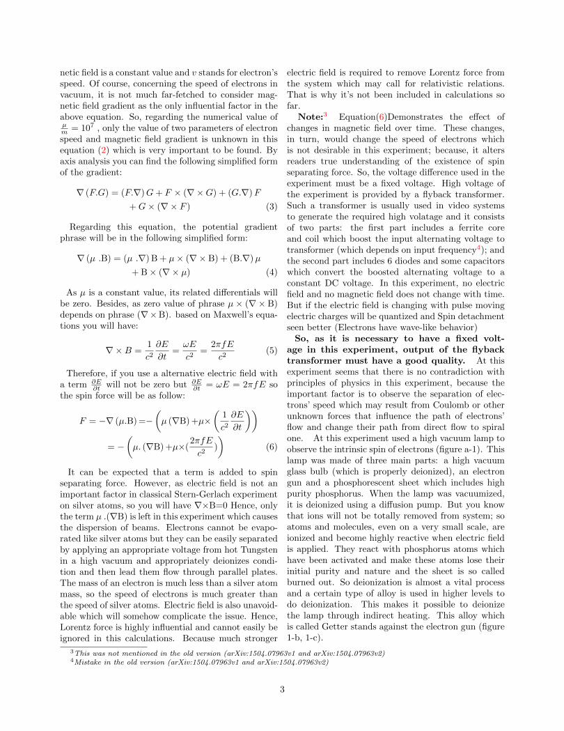
So, as it is necessary to have a fixed volt-age in this experiment, output of the flybacktransformer must have a good quality. At thisexperiment seems that there is no contradiction withprinciples of physics in this experiment, because theimportant factor is to observe the separation of elec-trons’ speed which may result from Coulomb or otherunknown forces that influence the path of electrons’flow and change their path from direct flow to spiralone. At this experiment used a high vacuum lamp toobserve the intrinsic spin of electrons (figure a-1). Thislamp was made of three main parts: a high vacuumglass bulb (which is properly deionized), an electrongun and a phosphorescent sheet which includes highpurity phosphorus. When the lamp was vacuumized,it is deionized using a diffusion pump. But you knowthat ions will not be totally removed from system; soatoms and molecules, even on a very small scale, areionized and become highly reactive when electric fieldis applied. They react with phosphorus atoms whichhave been activated and make these atoms lose theirinitial purity and nature and the sheet is so calledburned out. So deionization is almost a vital processand a certain type of alloy is used in higher levels todo deionization. This makes it possible to deionizethe lamp through indirect heating. This alloy whichis called Getter stands against the electron gun (figure1-b, 1-c).
3This was not mentioned in the old version (arXiv:1504.07963v1 and arXiv:1504.07963v2)4Mistake in the old version (arXiv:1504.07963v1 and arXiv:1504.07963v2)
3
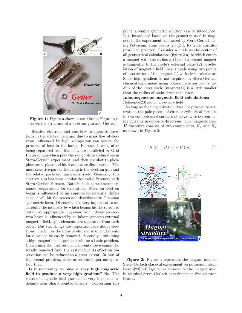
Figure 1: Figure a shows a used lamp; Figure b,cshows the structure of a electron gun and Getter.
Besides, electrons and ions flow in opposite direc-tions in the electric field and due to mass flow of elec-trons influenced by high voltage,you can ignore thepresence of ions in the lamp. Electron beams, afterbeing separated from filament, are paralleled by GridPlates of gun which play the same role of collimators inStern-Gerlach experiment, and then are shot to phos-phorescent plate and hit it and cause illumination. Themost sensitive part of the lamp is the electron gun andthe related parts set much sensitively. Generally, thiselectron gun has some similarities and differences withStern-Gerlach furnace. Both include some thermody-namic preparations for separation. When an electronbeam is influenced by an appropriate potential differ-ence, it will hit the screen and distributed in Guassiansymmetric form. Of course, it is very important to setcarefully the intensity by which beams hit the screen toobtain an appropriate Guassian form. When an elec-tron beam is influenced by an inhomogeneous externalmagnetic field, spin elements are separated from eachother. But two things are important here about elec-trons: firstly , as the mass of electron is small, Lorentzforce cannot be easily removed. Secondly , obtaininga high magnetic field gradient will be a basic problem.Concerning the first problem, Lorentz force cannot betotally removed from the system but its effect on ob-servation can be reduced to a great extent. In case ofthe second problem, there arises the important ques-tion that:
Is it necessary to have a very high magneticfield to produce a very high gradient? No. Thevalue of magnetic field gradient is very high and in-definite near sharp pointed objects. Concerning this
point, a simple geometric solution can be introduced.It is introduced based on the geometry used in mag-nets in the experiment conducted by Stern-Gerlach us-ing Potassium atom beams [23],[24]. Its truth was alsoproved in practice. Consider a circle as the center ofall geometrical calculations (figure 2-a) to which entersa magnet with the radius a (1) and a second magnetis tangential to the circle’s external plane (2). Caclu-lation of magnetic field lines is made using two pointsof intersection of the magnet (1) with circle calculator.Since high gradient is not required in Stern-Gerlachclassical experiment using potassium atom beams, ra-dius of the lower circle (magnet(1)) is a little smallerthan the radius of main circle calculator.Inhomogeneous magnetic field calculations:Reference[23] sec 3. Two-wire field
So long as the magnetization does not proceed to sat-uration, the pole pieces, of circular cylindrical form,liein two equipotential surfaces of a two-wire system us-ing currents in opposite directions. The magnetic fieldH therefore consists of two components, H 1 and H 2
as shown in Figure 3:
H (r) = H (r1) +H (r2) (7)
Figure 2: Figure a represents the magnet used inStern-Gerlach classical experiment on potassium atombeams[23],[24],Figure b-c represents the magnet usedin classical Stern-Gerlach experiment on free electronbeams.
4

Figure 3: Determination of a system of coordinates
Each of the two conductors contributes to the fieldas follows:
Hi (ri) =Ii × ri2πr2i
(i = 1, 2) (8)
WhereI1 = −I2 = I (9)
is the excitation current for the magnetic fields. Hence,at the point r ,
H (r) =2
2πI ×
(r1r21− r2r22
)(10)
The value of the magnetic field strength is obtained bysquaring this expression. remembering in the subse-quent calculation that r1 and r2 lie in a plane at rightangles to l, one finally obtains:
H =I
π
a
r1r2(11)
The change in the value of H as a function of z can becalculated, using
r21 = (a− y)2
+ (z + z0)2
(12)
Andr22 = (a+ y)
2+ (z + z0)
2(13)
as
∂H
∂z= −I.a(z + z0)
2
π×(r21 + r22
)r31r
32
=
=2I.a(z + z0)
2
π×
× a2 + y2 + (z + z0)2(
(a2 − y2)2
+ 2(z + z0)2
(a2 + y2) + (z + z0)4) 3
2
(14)
The surfaces of constant field inhomogeneity areshown in (Figure 4).
Figure 4: Lines of constant field inhomogeneity.
The equipotential surfaces in the neighbourhood of z= z1, are to be regarded as planes, to a good approx-imation. it must now find the plane z = z1, in whichthe equipotential surfaces are as plane as possible, andhow far this plane lies from the plane containing thewires, z=z 0.To do this, the length of the element ofpath (z 0+ z 1) will be determined, subject to the con-dition that,in the neighbourhood of y=0, ∂H
∂z is inde-
pendent of y. If one develops ∂H∂z in a series of y2 and
breaks this off after the first order, on the assumptionthat y2 is small compared with (z 0+ z 1)2 or a2, thefield gradients are found to be
∣∣∣∣∂H∂z∣∣∣∣z1
=2I.a (z0 + z1)
π(15)
Dependence on y is to vanish at z = z1. We then get:
2a2 − (z0 + z1)2
= 0 (16)
from which is follows that
z1 + z2 = a.√
2 (17)
The field inhomogeneity begins to decrease steeplywith increasing y only at greater distances along thez-axis. The present apparatus has a diaphragm systemin which the length of the radiation window is about4/3 a.
5
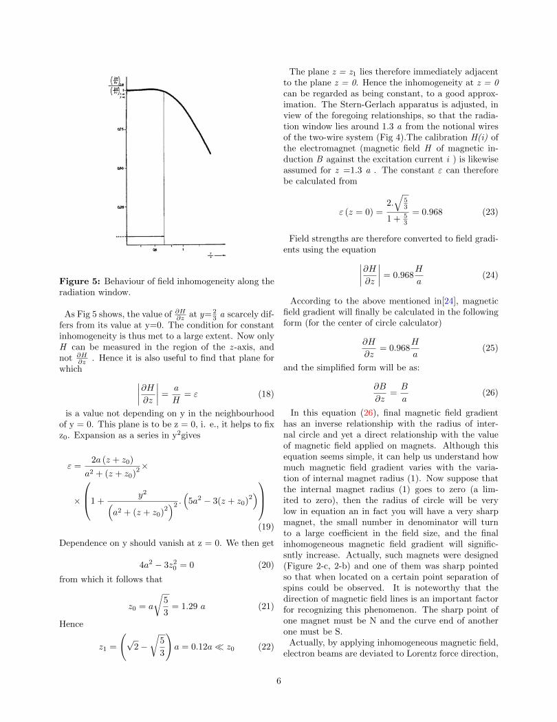
Figure 5: Behaviour of field inhomogeneity along theradiation window.
As Fig 5 shows, the value of ∂H∂z at y= 23 a scarcely dif-
fers from its value at y=0. The condition for constantinhomogeneity is thus met to a large extent. Now onlyH can be measured in the region of the z -axis, andnot ∂H
∂z . Hence it is also useful to find that plane forwhich ∣∣∣∣∂H∂z
∣∣∣∣ =a
H= ε (18)
is a value not depending on y in the neighbourhoodof y = 0. This plane is to be z = 0, i. e., it helps to fixz0. Expansion as a series in y2gives
ε =2a (z + z0)
a2 + (z + z0)2×
×
1 +y2(
a2 + (z + z0)2)2 .(5a2 − 3(z + z0)
2)
(19)
Dependence on y should vanish at z = 0. We then get
4a2 − 3z20 = 0 (20)
from which it follows that
z0 = a
√5
3= 1.29 a (21)
Hence
z1 =
(√
2−√
5
3
)a = 0.12a� z0 (22)
The plane z = z1 lies therefore immediately adjacentto the plane z = 0. Hence the inhomogeneity at z = 0can be regarded as being constant, to a good approx-imation. The Stern-Gerlach apparatus is adjusted, inview of the foregoing relationships, so that the radia-tion window lies around 1.3 a from the notional wiresof the two-wire system (Fig 4).The calibration H(i) ofthe electromagnet (magnetic field H of magnetic in-duction B against the excitation current i ) is likewiseassumed for z =1.3 a . The constant ε can thereforebe calculated from
ε (z = 0) =2.√
53
1 + 53
= 0.968 (23)
Field strengths are therefore converted to field gradi-ents using the equation∣∣∣∣∂H∂z
∣∣∣∣ = 0.968H
a(24)
According to the above mentioned in[24], magneticfield gradient will finally be calculated in the followingform (for the center of circle calculator)
∂H
∂z= 0.968
H
a(25)
and the simplified form will be as:
∂B
∂z=B
a(26)
In this equation (26), final magnetic field gradienthas an inverse relationship with the radius of inter-nal circle and yet a direct relationship with the valueof magnetic field applied on magnets. Although thisequation seems simple, it can help us understand howmuch magnetic field gradient varies with the varia-tion of internal magnet radius (1). Now suppose thatthe internal magnet radius (1) goes to zero (a lim-ited to zero), then the radius of circle will be verylow in equation an in fact you will have a very sharpmagnet, the small number in denominator will turnto a large coefficient in the field size, and the finalinhomogeneous magnetic field gradient will signific-sntly increase. Actually, such magnets were designed(Figure 2-c, 2-b) and one of them was sharp pointedso that when located on a certain point separation ofspins could be observed. It is noteworthy that thedirection of magnetic field lines is an important factorfor recognizing this phenomenon. The sharp point ofone magnet must be N and the curve end of anotherone must be S.
Actually, by applying inhomogeneous magnetic field,electron beams are deviated to Lorentz force direction,
6

spin force will separate electrons’ spin and split the ini-tial beam into two beams which can be easily observedby eyes and are at close distance to each other. Byincreasing the strength of magnetic field, beams willget more away compared to their initial distance andhave a better image of separation. The image qualityof spin separation depends on three factors: electricfield, and the distance of magnets from exit apertureof electron gun.
A question may come to your mind that:Can objective observation be the result of
Lorentz force? Since the mass of electrons and theelectric field is very small, Lorentz force cannot beremoved from system but it can be observed simulta-neously in the experiment and distinguished accordingto the extent which electron beams travel. What canbe observed in practice is that when inhomogeneousmagnetic field is applied, the initial single electronbeam split into two beams very close to each other (10micro meter to 100 micro meter) and the two beamstravel together(at the one time). Besides, due to sizeof the magnetic field used in the experiment, Lorentzforce exerted a deviation of some millimeters or aboutone or some centimeters, the extent of which can beeasily distinguished from separating force of electron’sspin.Beams are split into two beams only when the
applied magnetic field is inhomogeneous.(figure6-a, 6-b).
Figure 6: Figure a represents an electron beam be-fore applying an inhomogeneous magnetic field. Figureb represents a pair-beam electron after applying theinhomogeneous magnetic field (using a stationary mag-net) and the two beams travel together.
May the objective observation result from vari-ation of electron velocity distribution?(differentvelocity) It’s important note. If there is variation inelectron velocity distribution, it may seem as separa-tion(?).
But this may never happen in this experiment asthe electric field is constant (according to the electronvelocity order). to This can be tested in practice andconvinced that if two flat magnets are used instead ofgradient magnets, you can expect that electrons travel
exactly according to Lorentz force and if there is varia-tion in electron velocity distribution, it will be provedwell. This hypothesis was tested and found that whenflat magnets are used: the single-beams merely travelaccording to Lorentz force and no split was reported.So this would occur only in the presence of gradientand all electrons have the same speed.So, Beams are split into two beams only when the
applied magnetic field is inhomogeneous.Does the direction of electric field lines
change? No, electric field voltage is fed and strength-ened by diodes and capacitors.
you observed that along the widthwise direction ofelectrons emission, too much static electricity is gener-ated which is a good evidence that suggests it is verylikely that electrons do not travel in a quite directpath. Besides, this can clearly be observed when volt-age is reduced to a certain extent. The charge of staticelectricity around the lamp greatly affect the path ofelectrons so that it requires to place objects close tothe earth in order to eliminate this effect and avoidany intervention in the result. As voltage increases,the quality of paired image tends to decrease so thatthere will no longer be enough resolution. When thevoltage is very low, no image can be observed. It isevident that as electric field changes, the length ofelectron-bunch train emitted from gun will change andthis in turn affect the quality and resolution of theimage. By applying an inhomogeneous magnetic field,distribution of Guassian beam changes. So far, allcalculations were made based on the hypothesis thatelectrons travel through a direct path in the spacewhich originates from a classical view. On the otherhand, all calculations made on electron velocity so farfocused on single electrons, while there is no single orindividual electron in reality. So one consequence forholding this view would be to ignore coulomb force orother similar forces. Therefore, when some electronstravel together closely, the repulsion and attractionbetween them place them in a balanced distance toeach other. If an electric field, under a certain voltage,make electrons move along the spiral pattern in space(figure 7-a) one can claim that electron impulses be-fore applying the inhomogeneous magnetic field wouldnot be merely limited to moving along the directionof electrons. But components of the impulse axis foreach electron is polarized along with the screen forelectrons flow. So the impulses will be significantlyreduced along with the electron emission. Hence, itis evident that electrons will have much more timeto interact with inhomogeneous magnetic field (figure7-b) and you can see more separation distance whichwas seen in practice.
7
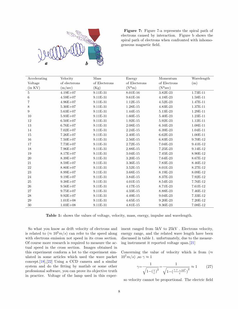
Figure 7: Figure 7-a represents the spiral path ofelectrons caused by interaction. Figure b shows thespiral path of electrons when confronted with inhomo-geneous magnetic field.
Accelerating
Voltage
(in KV)
Velocity
of electerons
(m/sec)
Mass
of Electerons
(Kg)
Energy
of Electerons
(N*m)
Momentum
of Electrons
(N*sec)
Wavelength
(m)
5 4.19E+07 9.11E-31 8.01E-16 3.82E-23 1.73E-11
6 4.59E+07 9.11E-31 9.61E-16 4.18E-23 1.58E-11
7 4.96E+07 9.11E-31 1.12E-15 4.52E-23 1.47E-11
8 5.30E+07 9.11E-31 1.28E-15 4.83E-23 1.37E-11
9 5.63E+07 9.11E-31 1.44E-15 5.13E-23 1.29E-11
10 5.93E+07 9.11E-31 1.60E-15 5.40E-23 1.23E-11
12 6.50E+07 9.11E-31 1.92E-15 5.92E-23 1.12E-11
13 6.76E+07 9.11E-31 2.08E-15 6.16E-23 1.08E-11
14 7.02E+07 9.11E-31 2.24E-15 6.39E-23 1.04E-11
15 7.26E+07 9.11E-31 2.40E-15 6.62E-23 1.00E-11
16 7.50E+07 9.11E-31 2.56E-15 6.83E-23 9.70E-12
17 7.73E+07 9.11E-31 2.72E-15 7.04E-23 9.41E-12
18 7.96E+07 9.11E-31 2.88E-15 7.25E-23 9.14E-12
19 8.17E+07 9.11E-31 3.04E-15 7.45E-23 8.90E-12
20 8.39E+07 9.11E-31 3.20E-15 7.64E-23 8.67E-12
21 8.59E+07 9.11E-31 3.36E-15 7.83E-23 8.46E-12
22 8.80E+07 9.11E-31 3.52E-15 8.01E-23 8.27E-12
23 8.99E+07 9.11E-31 3.68E-15 8.19E-23 8.09E-12
24 9.19E+07 9.11E-31 3.84E-15 8.37E-23 7.92E-12
25 9.38E+07 9.11E-31 4.01E-15 8.54E-23 7.76E-12
26 9.56E+07 9.11E-31 4.17E-15 8.71E-23 7.61E-12
27 9.75E+07 9.11E-31 4.33E-15 8.88E-23 7.46E-12
28 9.92E+07 9.11E-31 4.49E-15 9.04E-23 7.33E-12
29 1.01E+08 9.11E-31 4.65E-15 9.20E-23 7.20E-12
30 1.03E+08 9.11E-31 4.81E-15 9.36E-23 7.08E-12
Table 1: shows the values of voltage, velocity, mass, energy, impulse and wavelength.
So what you know as drift velocity of electrons andis related to (≈ 105m/s) can refer to the speed alongwith electrons emission not speed in its cross section.Of course more research is required to measure the ac-tual speed in the cross section. Images obtained inthis experiment conform a lot to the experiment sim-ulated in some articles which used the wave packetconcept.[18],[22] Using a CCD camera and a similarsystem and do the fitting by matlab or some otherprofessional software, you can prove its objective truthin practice. Voltage of the lamp used in this exper-
iment ranged from 5kV to 25kV . Electrons velocity,energy range, and the related wave length have beendiscussed in table 1. unfortunately, due to the measur-ing instrument it reported voltage span.[21]
Concerning the value of velocity which is from (≈107m/s) ,so γ ≈ 1
γ=1√
1−(vc )
2=
1√1−( ?.? ∼107
c )2≈ 1 (27)
so velocity cannot be proportional. The electric field
8
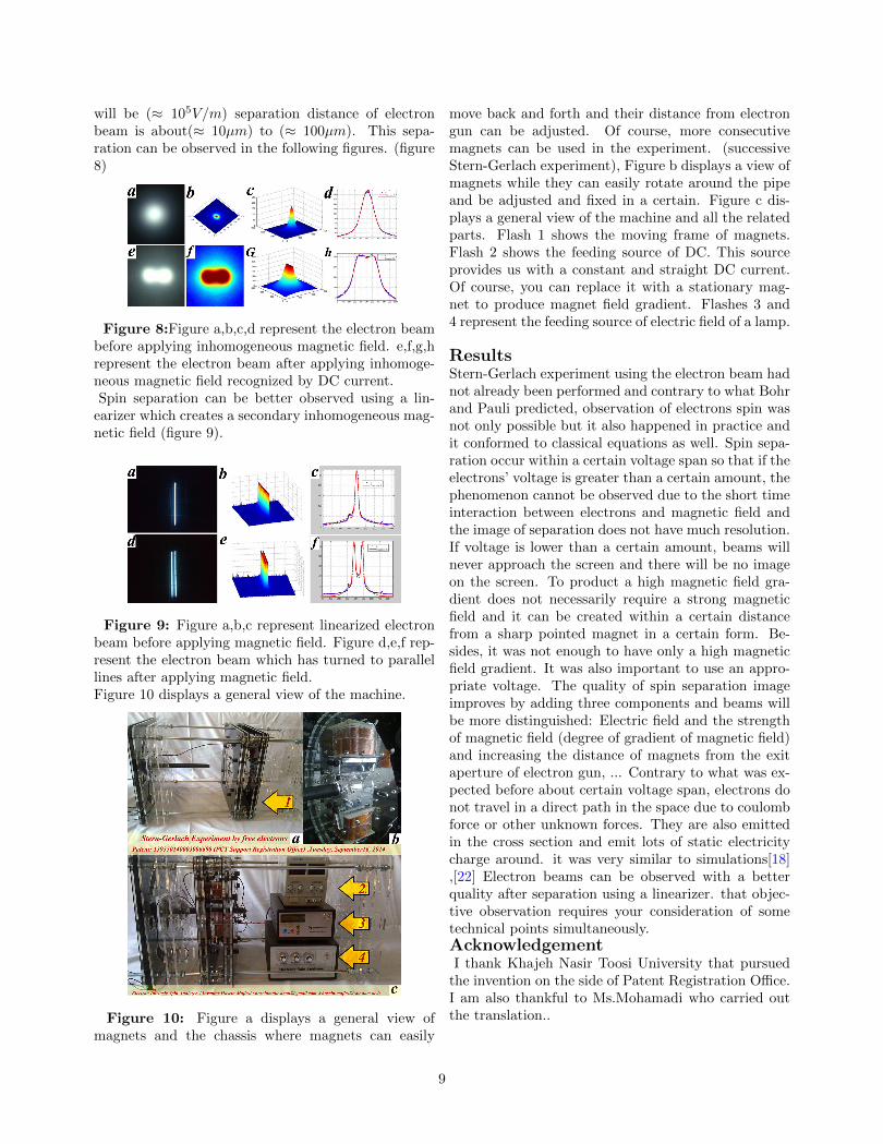
will be (≈ 105V/m) separation distance of electronbeam is about(≈ 10µm) to (≈ 100µm). This sepa-ration can be observed in the following figures. (figure8)
Figure 8:Figure a,b,c,d represent the electron beambefore applying inhomogeneous magnetic field. e,f,g,hrepresent the electron beam after applying inhomoge-neous magnetic field recognized by DC current.Spin separation can be better observed using a lin-
earizer which creates a secondary inhomogeneous mag-netic field (figure 9).
Figure 9: Figure a,b,c represent linearized electronbeam before applying magnetic field. Figure d,e,f rep-resent the electron beam which has turned to parallellines after applying magnetic field.Figure 10 displays a general view of the machine.
Figure 10: Figure a displays a general view ofmagnets and the chassis where magnets can easily
move back and forth and their distance from electrongun can be adjusted. Of course, more consecutivemagnets can be used in the experiment. (successiveStern-Gerlach experiment), Figure b displays a view ofmagnets while they can easily rotate around the pipeand be adjusted and fixed in a certain. Figure c dis-plays a general view of the machine and all the relatedparts. Flash 1 shows the moving frame of magnets.Flash 2 shows the feeding source of DC. This sourceprovides us with a constant and straight DC current.Of course, you can replace it with a stationary mag-net to produce magnet field gradient. Flashes 3 and4 represent the feeding source of electric field of a lamp.
ResultsStern-Gerlach experiment using the electron beam hadnot already been performed and contrary to what Bohrand Pauli predicted, observation of electrons spin wasnot only possible but it also happened in practice andit conformed to classical equations as well. Spin sepa-ration occur within a certain voltage span so that if theelectrons’ voltage is greater than a certain amount, thephenomenon cannot be observed due to the short timeinteraction between electrons and magnetic field andthe image of separation does not have much resolution.If voltage is lower than a certain amount, beams willnever approach the screen and there will be no imageon the screen. To product a high magnetic field gra-dient does not necessarily require a strong magneticfield and it can be created within a certain distancefrom a sharp pointed magnet in a certain form. Be-sides, it was not enough to have only a high magneticfield gradient. It was also important to use an appro-priate voltage. The quality of spin separation imageimproves by adding three components and beams willbe more distinguished: Electric field and the strengthof magnetic field (degree of gradient of magnetic field)and increasing the distance of magnets from the exitaperture of electron gun, ... Contrary to what was ex-pected before about certain voltage span, electrons donot travel in a direct path in the space due to coulombforce or other unknown forces. They are also emittedin the cross section and emit lots of static electricitycharge around. it was very similar to simulations[18],[22] Electron beams can be observed with a betterquality after separation using a linearizer. that objec-tive observation requires your consideration of sometechnical points simultaneously.AcknowledgementI thank Khajeh Nasir Toosi University that pursued
the invention on the side of Patent Registration Office.I am also thankful to Ms.Mohamadi who carried outthe translation..
9
References
[1] Electron Spin and Its History - Physics , Prince-ton University
[2] George Uhlenbeck and the discovery of electronspin,www.lorentz.leidenuniv.nl
[3] W. Gerlach and O. Stern, Z. Phys. 9, 349 (1922)
[4] N. Bohr, Nature.London.121, 580 (1928)
[5] N. Bohr, J. Chem. Soc.134, 349 ,(1932)
[6] Pauli W 1932 Proc. of the 6th Solvay Conf. 2(1930) (Brussels: Gauthier-Villars) pp 183–6,217–20, 275–80
[7] W. Pauli, Handbuch der Physik (Springer, Berlin,1958), vol. 1, chap. Secs. 9, 12, 23.
[8] L. Brillouin, Proc. Natl. Acad. Sci. U.S.A. 14, 755(1928)
[9] W. Pauli, in Proceedings of the Sixth SolvayConference (Gauthier-Villars, Brussels, 1932),pp.183,186, 217,220,275,280.
[10] N. Mott, Proc. R. Soc. (London) A 124, 425(1929).
[11] Mott and Massley, The Theory of Atomic Colli-sions (Oxford University Press, 1965),chap. IX.1.
[12] O. Klemperer, Electron Physics (Butterworths,1961).
[13] a letter to N. F. Mott in (1929)
[14] Dehmelt H 1988 New continuous Stern-Gerlacheffect and a hint of ‘the’ elementary particle Z.Phys.
[15] Dehmelt H 1990 Experiments with an isolatedsubatomic particle at rest Rev. Mod. Phys.
[16] H. Batelaan, T. J. Gay, and J. J. Schwendiman,Phys. Rev. Lett. 79, 4517 (1997).
[17] G. Rutherford and R. Grobe, J. Phys. A 31, 9331(1998).
[18] B. M. Garraway and S. Stenholm, Phys. Rev. A60, 63 (1999).
[19] G. A. Gallup, H. Batelaan, and T. J. Gay, Phys.Rev. Lett. 86, 4508 (2001).
[20] H. Batelaan ,Transverse quantum Stern–Gerlach magnets for electrons, New Journal ofPhysics,(2011)
[21] http://www.ou.edu/research/electron/bmz5364/calc-kv.html
[22] CONTROL AND MEASUREMENT OF QUAN-TUM SPINS: THEORY AND SIMULATIONS.Suguru Furuta. Darwin College. University ofCambridge (2005)
[23] Stern-Gerlach experiment by Potassium atombeams/ www.phywe.com / Stern-Gerlach exper-iment/ Manual/ LEP 5.1.11 Stern-Gerlach exper-iment,
[24] The Stern Gerlach Experiment ,Jeff LiebermanDepartment of Physics, Massachusetts Instituteof Technology (June 22,1998)
Figure References: Figure 1-b:Internet Figure 2-a,3,4,5 :[23]
10