Observing Lake Erie Algae Blooms via Hyper Spectral Imaging on CubeSat
21
Emr 1 Observing Lake Erie Algae Blooms via Hyper Spectral Imaging on CubeSat Chris Emr, Department of Physics Advisor: Professor Paul Barnhart, Department of Aerospace Engineering Case Western Reserve University Department of Physics May 1, 2013
Transcript of Observing Lake Erie Algae Blooms via Hyper Spectral Imaging on CubeSat

Emr 1
Observing Lake Erie Algae Blooms via
Hyper Spectral Imaging on CubeSat
Chris Emr, Department of Physics
Advisor: Professor Paul Barnhart, Department of Aerospace Engineering
Case Western Reserve University
Department of Physics
May 1, 2013

Emr 2
Abstract
I present a design to develop a hyper-spectral imaging instrument that can be integrated
within a CubeSat to provide orbital observations of Lake Erie from a low earth orbit. This
design must be no larger than 10 cm by 10 cm by 10 cm in order to fit into a single CubeSat unit.
This instrument will be used to identify the creation of algae blooms in Lake Erie and requires a
30 meter by 30 meter ground resolution per pixel. With this requirement, 8 megapixels is the
minimum camera resolution needed to capture the region of the lake with high algae
concentrations. An instrument of these requirements is possible to create. A prototype of larger
scale is created with some lighting, camera exposure and analysis issues. If taken to launch, this
project will be able to provide data for years with little to no additional cost other than the initial
development and launch. This could lead to identifying the cause of the blooms and finding
possible ways to eradicate these blooms in the future.
Introduction
Hyperspectral analysis is very useful in aerial surveillance of minerals and substance
identification. Different materials emit wavelengths of light, in the visible and non-visible
spectrum. By analyzing these wavelengths, hyperspectral imagers are able to identify the type of
material and thus this can be used for specific and specialized tasks. Most imagers of this type
are large and expensive to build, often ranging in the tens of thousands of dollars. The goal of
this project is to develop a miniaturized hyperspectral imaging instrument that could be
integrated within a CubeSat to provide orbital observations of Lake Erie algae blooms from a
low earth orbit. CubeSat is a small square satellite that can be manufactured relatively cheaply

Emr 3
compared to most satellites. A realistic goal for an instrument such as this would be well under a
thousand dollars while still producing viable and informative scientific data.
This instrument will be used to identify the creation of algae blooms in Lake Erie. The
current methods of collecting data on algae blooms include spot checking by boat or pre-built
stations and air born identification by plane. Both of these methods are inefficient and expensive
to perform periodically enough to get scientific data that might help with the eradication of these
harmful blooms in the Lake Erie ecosystem.
Once a project such as this is taken to launch scientists will be able to gather much more
data on the growth of these algae blooms. This could lead to identifying the cause of the blooms
and possibly ways to eradicate these blooms in the future. Until then, these algae blooms will
continue to harm the environment and the ecosystem it inhabits.
Background on Algae Blooms
Algae blooms that occur in Lake Erie on an annual basis disrupt the ecosystem of the lake
killing fish and other underwater life. This algae blooms are thought to blossom when high
amounts of phosphorus from fertilizer run off is present after heavy storm seasons [1]. There
have been some decreases in the blooms due to phosphorus eradication efforts that have been
enforce. However, in recent years the blooms have increased greatly with little explanation. The
current methods of locating these blooms include testing the lake by boat, imaging by airplane
and spot testing the lake at specified locations. Testing by boat is time consuming, by airplane is
time consuming and expensive and spot checking is not accurate enough to detect trends that
could lead to the eventual prevention of these algae blooms. A hyperspectral imager taking data
of the lake via satellite will allow for accurate, regular detection with little time consumption and

Emr 4
only a high initial cost. Similar imagers have been used to trend forest fires and have assisted in
the prevention and eradication of these fires [2].
Background on Hyperspectral Imaging
Hyperspectral imaging occurs through a process of a field of view being passed through
an imaging spectrometer. Spectrometers allow for the analysis of individual ranges of
wavelengths to be viewed. This method of visual analysis is particularly useful during the remote
imaging of earth and its materials, such as the algae we will be observing. Multispectral imaging
is very similar to hyperspectral imaging in its uses, but the resulting output is often different.
Multispectral imaging focuses on a fewer number of wavelengths over broad spectral bands.
Although this is still useful, material identification is more accurate with a continuum of spectral
analysis focusing on many spectral bands [7]. Within the scientific community there is no exact
distinction between multispectral and hyperspectral. This fairly arbitrary categorization makes it
so there is no precise number of spectral bands that can cause an imager to be clearly identified
as hyperspectral or multispectral.
Due to the nature of these instruments, both types of these imaging spectrometers,
hyperspectral and multispectral, create a cube of data. This cube of data has dimensions of
spatial by spatial by spectral. The spectral range and resolution depends on the nature of the
instrument and the spatial range is created by the attitude of the instrument and the duration of
the exposure time of the camera. The spatial range and resolution will also depend on the size of
the field of view of the instrument which is also based on the optical configuration [7]. A
multispectral cube will often have breaks in the spectral axis where as a hyperspectral cube will
have a nearly continuous spectrum.

Emr 5
Figure 1 below shows the basics utilities in a hyperspectral imager. The feasibility study
will include conducting calculations to confirm each lens will allow for the proper sizing
requirement of this instrument. The entirety of this instrument, while disregarding the initial
turnable mirror can be thought of as two individual specialized cameras. The front lens, slit,
collector lens and diffraction grating is the first specialized camera and the camera lens and
detector is a second, off the shelf camera. The specialized camera takes the view and sends
images it on the grating instead of a sensor. The second camera then takes that image created, re-
images it and projects it onto the detector.
Figure 1: This diagram shows a very basic layout of the inner workings of a whiskbroom
hyperspectral imager [3]. My imager will have all the same aspects without the tunable mirror at
the leading edge. The lack of this mirror makes my design a push-broom hyperspectral imager
[2]. The design of my imager also excludes the CCD detector and camera lens. For my purposes,
I only require a basic off the shelf 8 mega pixel camera. This pixel count allows for the imager to
take a shot of the entirety of Lake Erie with the proper ground resolution needed.

Emr 6
Going through each part of Figure 1 will make clear the inner workings of hyperspectral
imagers. The front lens is used to image the scene onto to the slit. The light then diverged
through the slit aperture. The intensity pattern that is created by this slit is projected onto the
collecting lens. This lens collimates the light or makes it parallel to the path it travels which is
now perpendicular to the diffraction grating. A diffraction grating is a film of very small slits
placed very close together. Higher quality transmission gratings are made of glass and are
created by etchings on one side to diffract the light. The diffraction film grating here passes the
original image directly though while spreading or diffracting the different wavelengths in a
vertical direction, perpendicular to the path of the light traveling. The higher frequency and
lower wavelength and higher energy wavelengths diffract more than the lower frequency and
lower energy wavelengths. This allows the dispersion of wavelengths to occur. The camera lens
then again collimates the now dispersed wavelengths and projects them on the detector to be
collected. A final output of a 2 dimensional, spectral by spatial image is now created.
A unique aspect of this design is the interchangeability of the slit apparatus with a square
slit apparatus. A square slit apparatus, as used in this proposed design in this paper allows for the
output to become spatial by spatial by spectral without having to compile the individual slices of
data that are otherwise created by a slit apparatus. The use of the square apparatus depreciates
the resolution of the spectral data slightly, but for certain purposes, this is still a viable option.
Background on Space Mission Design for a Pico-satellite
There are many aspects to consider when designing a satellite, especially one on this
scale. This proposed project will just cover the instruments development process. The instrument
or payload of the satellite will include this instrument, a telescope for viewing, a camera for
Emr 7
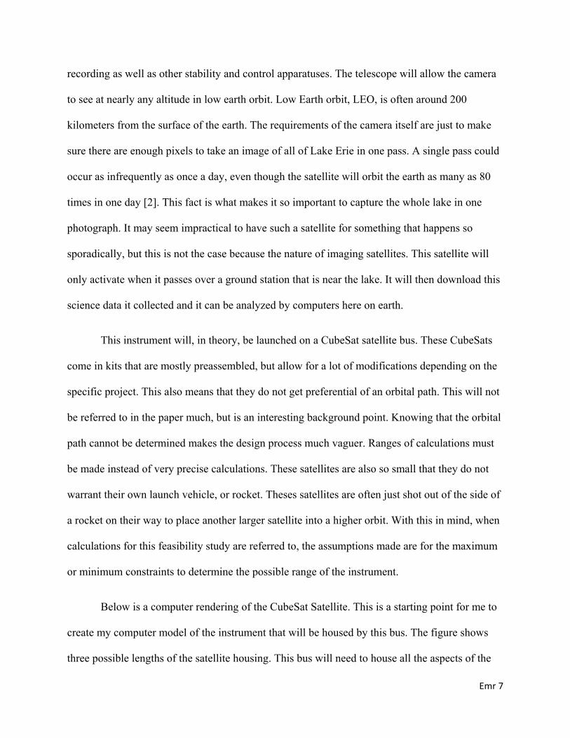
recording as well as other stability and control apparatuses. The telescope will allow the camera
to see at nearly any altitude in low earth orbit. Low Earth orbit, LEO, is often around 200
kilometers from the surface of the earth. The requirements of the camera itself are just to make
sure there are enough pixels to take an image of all of Lake Erie in one pass. A single pass could
occur as infrequently as once a day, even though the satellite will orbit the earth as many as 80
times in one day [2]. This fact is what makes it so important to capture the whole lake in one
photograph. It may seem impractical to have such a satellite for something that happens so
sporadically, but this is not the case because the nature of imaging satellites. This satellite will
only activate when it passes over a ground station that is near the lake. It will then download this
science data it collected and it can be analyzed by computers here on earth.
This instrument will, in theory, be launched on a CubeSat satellite bus. These CubeSats
come in kits that are mostly preassembled, but allow for a lot of modifications depending on the
specific project. This also means that they do not get preferential of an orbital path. This will not
be referred to in the paper much, but is an interesting background point. Knowing that the orbital
path cannot be determined makes the design process much vaguer. Ranges of calculations must
be made instead of very precise calculations. These satellites are also so small that they do not
warrant their own launch vehicle, or rocket. Theses satellites are often just shot out of the side of
a rocket on their way to place another larger satellite into a higher orbit. With this in mind, when
calculations for this feasibility study are referred to, the assumptions made are for the maximum
or minimum constraints to determine the possible range of the instrument.
Below is a computer rendering of the CubeSat Satellite. This is a starting point for me to
create my computer model of the instrument that will be housed by this bus. The figure shows
three possible lengths of the satellite housing. This bus will need to house all the aspects of the

Emr 8
satellite including the telescope, the imager, the camera, the star locator, the attitude and control
and the power source. The instrument itself will hopefully be able to fit inside a single unit. The
rest of the components will most likely require 3 units total as the imager requires high point
accuracy in order to makes sure we get the desired pictures of the lake. One unit is about ten
centimeters in length, width and height. These unit chassis are shown in diagram 2 on the next
page.
Figure 2: This schematic shows some of the possible sizes in which the CubeSat bus can be
launched. The 3 unit size will most likely be required for this project [4].
The nature of hyperspectral imagers make them ideal for identifying materials that give
off a unique wavelength compared to its surroundings. This property allows the imager to
identify green algae blooms very clearly in the dark waters of Lake Erie. Once the image reaches
the imager the light the object gave off is passed through a slit to create a spectrograph that is an

Emr 9
intensity function with respect to wavelength and position. The next lens and diffraction grating
then collect and focus the spectrograph for the camera to interpret it properly.
Objectives
There are many design aspects that need to be taken into consideration when designing
the payload for a satellite. In general, this covers the functionality of the instrument, in a lab
setting and in space, the size limitations that the space craft allows and the fragility of the
materials that will be used in a space environment. This project is limited to the functionality of
the instrument in a lab setting. This being said, there are many other aspects of the payload that
will need to be taken into account once the engineering design aspect of this mission is
attempted. These parameters include atmospheric coverage, deployment strategy, Orbit Period,
Time in view, Eclipse fraction, Response Time, Number of spacecraft needed, Launch
Capability, Resolution, Payload Weight, Radiation Environment, Survivability, Jamming
Susceptibility, Communications and Lifetime. The feasibility study of this mission was based on
requirements set on resolution and approximations made on orbital altitude, Orbital Period and
Time in view. Specifics of these calculations and assumptions are included in the Conclusion and
Results section.
The Objectives of this paper are to show the fesability of launching a hyperspectral
imaging instrument on a CubeSat bus and create a scale model prototype of the instrument in a
lab setting.
Review of Previous Works
A similar project was proposed once before with a similar goal, but the end product has
still not yet been reached. I used a published paper of this proposed project as a starting point for
my design. This design was intended to launch a hyperspectral imager on a pico-satellite very
Emr 10
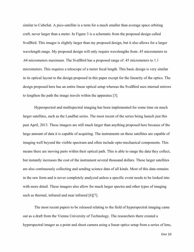
similar to CubeSat. A pico-satellite is a term for a much smaller than average space orbiting
craft, never larger than a meter. In Figure 3 is a schematic from the proposed design called
SvalBird. This imager is slightly larger than my proposed design, but it also allows for a larger
wavelength range. My proposed design will only require wavelengths from .45 micrometers to
.64 micrometers maximum. The SvalBird has a proposed range of .45 micrometers to 1.1
micrometers. This requires a telescope of a meter focal length. This basic design is very similar
in its optical layout to the design proposed in this paper except for the linearity of the optics. The
design proposed here has an entire linear optical setup whereas the SvalBird uses internal mirrors
to lengthen the path the image travels within the apparatus [3].
Hyperspectral and multispectral imaging has been implemented for some time on much
larger satellites, such as the LandSat series. The most recent of the series being launch just this
past April, 2013. These imagers are still much larger than anything proposed here because of the
large amount of data it is capable of acquiring. The instruments on these satellites are capable of
imaging well beyond the visible spectrum and often include opto-mechanical components. This
means there are moving parts within their optical path. This is able to range the data they collect,
but instantly increases the cost of the instrument several thousand dollars. These larger satellites
are also continuously collecting and sending science data of all kinds. Most of this data remains
in the raw form and is never completely analyzed unless a specific event needs to be looked into
with more detail. These imagers also allow for much larger spectra and other types of imaging
such as thermal, infrared and near infrared [6][7].
The most recent papers to be released relating to the field of hyperspectral imaging came
out as a draft from the Vienna University of Technology. The researchers there created a
hyperspectral imager as a point and shoot camera using a linear optics setup from a series of lens,

Emr 11
a diffraction grating and an off the shelf camera. This setup is nearly identical to my prototype
setup and the same design, although larger in scale, as the proposed design project. Figure 4
shows the camera with its spectrometer attachment as well as the internal workings of the
attachment including the lens and gratings used, just as in the lab prototype from this paper.
Figure 5 shows the optical configuration used by this research team and the proposed
configuration for the payload of the CubeSat in this paper.

Emr 12
Figure 3: This is the proposed design for SvalBird. This hyperspectral imager would be used to
capture a spectrum of wavelengths from .45 micrometers to 1.1 micrometes [3]. This imager is
designed to be earth imaging for any purpose a company may require such a device. The broad
purpose of the device may be one of the reasons this project has yet to come to completion.

Emr 13
Figure 4: Above is the internal layout of the point and shot DSLR hyperspectral camera. The
internal lenses shown and are very similar to the prototype modeled for this paper. The lenses
they used are basic off the shelf photographic lenses that most photographic enthusiasts would
have already. The tubing they used to piece together the spectrometer is basic PVC tubing. This
is just a complex version of the layout of a hyperspectral imager show in Figure 1.

Emr 14
Figure 5: This is the basic layout of a hyperspectral imager again, but in a 2 dimensional setting.
This is showing the primary optic path from entrance on the left to the sensor on the right. The
scale of this as created by the researchers in Vienna is between 30 and 40 centimeters. The same
approximate size of the prototype for this paper. The scaled down version for the feasibility
aspect of this paper puts this at just about 10 centimeters just allowing this to be a payload on a
CubeSat. Upon comparing figure 3 to figure 4, it can be seen that each of the lens used is in fact
several different lenses compounded. This is useful in a lab setting to lower costs and uses cheap
grab bag or off the shelf lenses. If this project were to be scaled down, custom lenses, sensors,
and gratings are recommended to increase quality and minimize size.
Methods and Results
First part of designing a fesability study is to create a list of the essential requirements
that cannot be manipulated. These are listed here:
• 30m ground resolution
• Low Earth Orbit (~200km)
• No larger than 1 unit length on CubeSat (10cmX10cmX10cm)
• 8 mega Pixel Camera
• Mission Life of 3-5 years
The imager will need to collect science data at a 30 meter by 30 meter per pixel ground
resolution. CubeSat is developed in units of 10 cm by 10 cm. The maximum number of CubeSat

Emr 15
units that can be adjoined contiguous is three. In order to allow for the proper point control,
power source and communication devices in the satellite, the imager must be limited to the size
of no larger than a single unit.
In order to make this method of data collection of the algae blooms cost effective
compared to the current methods, this satellite must have a mission life of at least three to five
years. This is manageable when setting the altitude of the spacecraft to an altitude of about 200
kilometers which also allows for acceptable imaging. For design purposes, it was determined the
imager’s ideal altitude occurs in Low Earth Orbit at 200 km. The 3-5 year mission life is simply
based on the possible altitude decay that can occur at those low levels. The robustness of the
instrument and payload itself was not taken into account because the parts used in the apparatus
would be completely different than the prototype and these parts were not available for
environmental testing, nor are there facilities to simulate all space environments readily available
to undergraduate researchers.
The optics equations needed to create this feasibility study and the prototype came from a
combination of lecture notes from my physics classes, online lectures and in papers. One
particularly useful online document was prepared by Olivier de Weck at MIT [5]. The Space
mission analysis and design manual also have several step by step guides to define sensor optics
of a earth remote sensing payload. Many of the key formulas used are listed here:
(1)
f is focal length, h is altitude, d is the width for the square detectors and X is the ground
pixel size. X is a requirement to be 30 m, h is given at 200 km and d is a design parameter of my

Emr 16
choosing. 30 micrometers for a square detector width on a camera is standard and this gives me a
focal length of 20 cm as shown in table 1.
. (2)
Where D is the width of the diffraction limited apperature, λ is the operating wavelength,
f is the focal length, Q is the quality factor of the camera pixels and d is the with for the square
detectors. In this case, f is 20 cm from (1), the operating wavelength is set at about .6
micrometers, a good and common quality factor for a camera is 1.1 and d is again common at 30
micrometers. This gives a D of 1.11 centimeters. This is the diameter of the square slit needed
for the proper resolutions.
The best form of imager is always diffraction limited because light is only able to bend so
much before certain optical noise makes the data unreadable. In order to make sure this is the
case for my instrument I carried through all the calculations to determine the necessary
components of the telescope and hyperspectral imager. These calculations were based on the
formulas in the methods section which were referenced from Space Mission Analysis and Design
[2]. The calculations I conducted for the viewing parameters of the telescope and satellite are
listed below in Table 1.
Angular Radius of Earth 75.84
Maximum distance to the Horizon 1610 kilometers
Maximum Incidence Angle 70 degrees
Sensor Look Angle (NADIR Angle) 52.2 degrees
Minimum Elevation Angle 20 degrees

Emr 17
Earth Central Angle 17.8 degrees
Slant Range 2467.5 kilometers
Swath Width 35.6 degrees
Maximum along track ground sampling 30 meters
Instantaneous Field of View .6966 degrees
Maximum cross-track pixel resolution 87.71 meters
Cross track ground pixel resolution 30 meters
along track ground pixel resolution 30 meters
Number of cross track pixels 40.47
Number of along track swaths recorded in 1 second 15.1
Number of pixels recorded in 1 second 610.9
Bits per Pixel 8
Data Rate Required 4.9 Kilobits per second
Table 1: viewing parameters of the telescope and satellite [2]
Table 2 includes the calculations required for the sensor optics. These are also based on the
Space Mission analysis text formula and assumptions from the methods section.
Width for square detectors 30 micrometers
Quality Factor 1.1
Operating wavelength range .5-.6 micrometes
Focal Length .2 meters
Diffraction limited aperture .0111 meters
F# 6

Emr 18
Cutoff Frequency .0895 lines pairs per meter
Nyquist Frequency .017 line pairs per meter
Table 2: Sensor Optics parameters required [2].
Other results obtained from this project is the computed model filtered image of Lake
Erie that simulates the before and after image of the expected output of the hyperspectral imager
once the project is taken to completion. The model was developed using the band pass filter
settings and other available options in the Matlab Photo Toolbox. Figure 6 shows the before
image and the after running the image through the computer modeled spectrometer.
Figure 6: The left image is a previously taken overhead image of Lake Erie during algae bloom
season. The right image is that same photo run through a filter that simulates the output of the
proposed hyperspectral imager.
Conclusion
There are many values in Tables 1 and 2 that have very little significant meaning to the
feasibility of this hyperspectral imager. Many of those numbers are aspects of the engineering

Emr 19
design that could help in the manufacturing of certain parts to ideal standards or even minimum
standards. Table 1 is entirely engineering design analysis barely used for the feasibility study.
These values come from almost entirely analysis of orbital mechanics of the satellite. The
important values to take away from the tables are the ground resolutions are 30 m by 30 m for
each pixel, meeting those requirements. A total minimum focal length of 20 centimeters is
achieved, which is longer than the 1 unit length of the CubeSat, but using compound lens and
proper use of mirrors, this focal length can be achieved in the minimum space.
In conclusion, the feasibility study of this instrument was a success and shows this
hyperspectral imager is possible to make given a much larger budget and time requirement than
an undergraduate senior project.
Discussion
The prototyping of this instrument in a lab setting proved to be more difficult than
previously anticipated. I encountered many of the same problems the researchers in Vienna
found when prototyping such an instrument. There can often be extra scattered light entering and
exiting the apparatus, especially when low quality lenses and gratings are used. A fix that I
attempted from their lead was wrapping the system in black, light absorbing paper. The
researchers from Vienna also used this in their PVC tubing when mounting the prototype. This
works to decrease the stray scattering, but other issues arise. The telephoto length of the lens is
far too long and not enough light is captured by the final sensor in the back of the imager. This
can be resolved by increasing the exposure time, but due to my photographic limitations there
were still issues adjusting this and gaining a proper output from my prototype. Adjustments are
still being made.

Emr 20
Future Work
This project will allow for the continuation of advanced science for both the Lake Erie
ecosystem as well as the resulting outcome of the imager itself. It is my expectation that now that
this project is proven possible and when a prototype is demonstrated as working, an interested
party will continue the research and development needed in order to take this project to fruition.
Developing a satellite and instrument is no trivial matter and this year long project could lead to
a multiple year endeavor to push the limits of hyperspectral imaging. This project is the next
logical step in hyperspectral imaging and the limits of this technology should be pushed in order
to attain the best possible science data. Imaging systems from space are becoming more and
more relevant to everyday life with GPS and Satellite mapping systems. More advanced
technology in this field could eventually change people’s everyday lives.

Emr 21
Bibliography
1 - NICHOLLS, K. (1997). Planktonic green algae in western Lake Erie: the importance of temporal scale in the interpretation of change. Freshwater Biology, 38(2), 419-425.
2 – Larson, Wiley J., Wertz, James R. (2004) Space Mission Analysis and Design. California, Microcosm Press
3 - Sigernes, F., Renner, U., Roemer, S., Bleif, J. H., Lorentzen, D. A., Claes, S., ... & Pedersen, S. (2005). Proposal for a new hyper spectral imaging micro satellite: SVALBIRD. In Small Satellites for Earth Observation: Selected Proceedings of the 5th International Symposium of the International Academy of Astronautics, Berlin, April 4-8 2005 (p. 134). De Gruyter.
4 – Pumpkin Inc. “CubeSat System Chart” http://www.cubesatkit.com/docs/cubesatkitsystemchart.pdf
5 - Weck, Olivier de. “Introduction to Optics” Ed. Chung, Soon-Jo. 2001. MIT Space Systems Laboratory. http://ocw.mit.edu/courses/aeronautics-and-astronautics/16-851-satellite-engineering-fall-2003/lecture-notes/l6_optics_1.pdf 6 - Moskal, L. M., Price, J. P., Jakubauskas, M. E., & Martinko, E. A. Comparison of hyperspectral AVIRIS and Landsat TM imagery for estimating burn site pine seedling regeneration densities in the Central Plateau of Yellowstone National Park.
7 – Smith, Randall B. (2012) Introduction to Hyperspectral Imaging. MicroImages, Inc. Lincoln, Nebraska www.microimages.com/documentation/Tutorials/hyprspec.pdf