Object-Oriented Systems Analysis and Design with...
30
Object-Oriented Systems Analysis and Design with UML
Transcript of Object-Oriented Systems Analysis and Design with...
Object-Oriented Systems Analysis and Design with UML
OBJECTIVES:
• Understand the basic characteristics of object-oriented systems.
• Be familiar with the Unified Modeling Language (UML), Version 2.0.
• Be familiar with the Unified Process.
• Understand a minimalist approach to object-oriented systems analysis and design.
BASIC CHARACTERISTICS OF OBJECT-ORIENTED SYSTEMS (1)
• Classes and Objects– A class is the general template we use to define
and create specific instances, or objects.– An object is an instantiation of a class. In other
words, an object is a person, place, event, or thing about which we want to capture information
– Each object has attributes that describe information about the object
– Each object also has behaviors. The behaviors specify what the object can do.
BASIC CHARACTERISTICS OF OBJECT-ORIENTED SYSTEMS (2)
• Methods and Messages– Methods implement an object’s behavior. A method is
nothing more than an action that an object can perform.– Messages are information sent to objects to trigger
methods. Essentially, a message is a function or procedure call from one object to another object.
• Encapsulation and Information Hiding– Encapsulation is simply the combination of process and
data into a single entity.– The principle of information hiding suggests that only the
information required to use a software module be published to the user of the module.
BASIC CHARACTERISTICS OF OBJECT-ORIENTED SYSTEMS (3)
• Inheritance– Subclasses inherit the appropriate attributes and
methods from the superclasses above them.– Most classes throughout a hierarchy will lead to
instances; any class that has instances is called a concrete class.
• Polymorphism and Dynamic Binding– Polymorphism means that the same message can be
interpreted differently by different classes of objects.– Polymorphism is made possible through dynamic
binding. Dynamic, or late, binding is a technique that delays typing the object until run-time.

THE UNIFIED MODELING LANGUAGE, VERSION 2.0
• The objective of UML is to provide a common vocabulary of object-oriented terms and diagramming techniques that is rich enough to model any systems development project from analysis through implementation.
• The Version 2.0 of the UML defines a set of fourteen diagramming techniques used to model a system. The diagrams are broken into two major groupings: one for modeling structure of a system and one for modeling behavior.
• The structure modeling diagrams include class, object, package, deployment, component, and composite structure diagrams.
Structure Diagrams (1)• Class Diagrams The primary purpose of the class diagram is
to create a vocabulary that is used by both the analyst and users. Class diagrams typically represent the things, ideas or concepts that are contained in the application.
• Object Diagrams Object diagrams are very similar to class diagrams. The primary difference is that an object diagram portrays objects and their relationships. The primary purpose of an object diagram is to allow an analyst to uncover additional details of a class.
• Package Diagrams Package diagrams are primarily used to group elements of the other UML diagrams together into a higher-level construct: a package. Package diagrams are essentially class diagrams that only show packages, instead of classes, and dependency relationships, instead of the typical relationships shown on class diagrams.

Structure Diagrams (2)• Deployment Diagrams Deployment diagrams are used to
represent the relationships between the hardware components used in the physical infrastructure of an information system.
• Component Diagrams Component diagrams allow the designer to model physical relationships among the physical modules of code. The diagram when combined with the deployment diagram can be used to portray the physical distribution of the software modules over a network.
• Composite Structure Diagrams The UML 2.0 provides a new diagram for when the internal structure of a class is complex: the composite structure diagram. Composite structure diagrams are used to model the relationships among parts of a class.
Structure Diagrams (3)• Deployment Diagrams Deployment diagrams are used to
represent the relationships between the hardware components used in the physical infrastructure of an information system.
• Component Diagrams Component diagrams allow the designer to model physical relationships among the physical modules of code. The diagram when combined with the deployment diagram can be used to portray the physical distribution of the software modules over a network.
• Composite Structure Diagrams The UML 2.0 provides a new diagram for when the internal structure of a class is complex: the composite structure diagram. Composite structure diagrams are used to model the relationships among parts of a class.
Behavior Diagrams• Activity Diagrams Activity diagrams provide the
analyst with the ability to model processes in an information system. Activity diagrams can be used to model workflows, individual use cases, or the decision logic contained within an individual method.
• Interaction Diagrams Interaction diagrams portray the interaction among the objects of an object-oriented information system. UML 2.0 provides four different interaction diagrams: sequence, communication, interaction overview, and timing diagrams.

Interaction Diagrams• Sequence diagrams emphasize the time-based
ordering of the activity that takes place with a set of collaborating objects.
• Communication diagrams depict how objects collaborate to support some aspect of the required functionality of the system.
• Interaction overview diagrams provide an overview of a process’s flow of control.
• Timing diagrams portray the interaction between objects along a time axis.

State machines
• Behavior state machines provide a method for modeling the different states, or sets of values, that instances of a class may go through during their lifetime
• Protocol state machines support the analyst in designing dependencies among elements of the class’ interface.
Use Case Diagrams• Use case diagrams allow the analyst to model
the interaction of an information system and its environment. The primary use of the use case diagram is to provide a means to document and understand the requirements of the evolving information system.
Extension Mechanisms• A stereotype provides the analyst with the ability to
incrementally extend the UML using the model elements already in the UML.
• There are times that it is useful to add properties to the base elements. Tagged values are used to add new properties to a base element.
• Constraints allow the analyst to model problem domain specific semantics by placing additional restrictions on the use of model elements.
• Profiles allow the developer to group a set of model elements that have been extended using stereotypes, tagged values, and/or constraints into a package.
Goals of Systems AnalysisPrimary Goal:• To state accurately the users’ requirements for a
new information processing systemSecondary Goals:1. To understand the users’ requirements.2. To communicate the current understanding of
the proposed system3. To prevent expensive mistakes4. To state a design problem5. To state the conditions for system acceptance
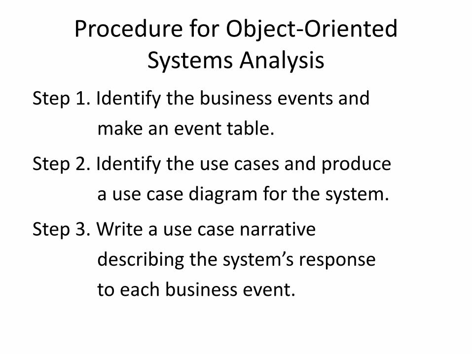
Procedure for Object-Oriented Systems Analysis
Step 1. Identify the business events and
make an event table.
Step 2. Identify the use cases and produce
a use case diagram for the system.
Step 3. Write a use case narrative
describing the system’s response
to each business event.
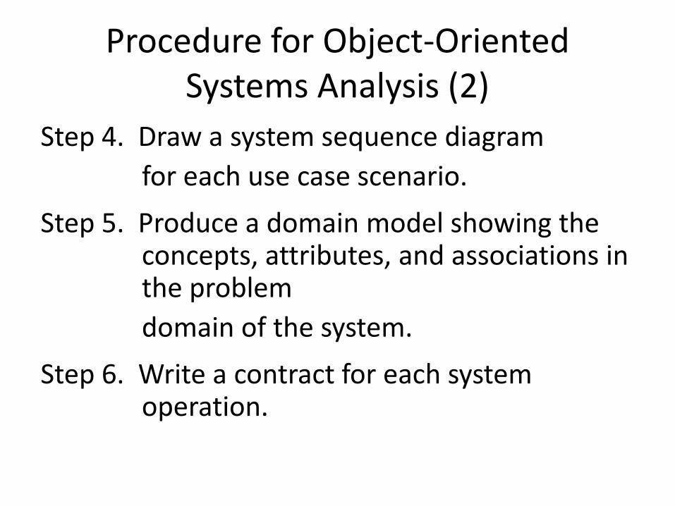
Procedure for Object-Oriented Systems Analysis (2)
Step 4. Draw a system sequence diagram for each use case scenario.
Step 5. Produce a domain model showing the concepts, attributes, and associations in the problem domain of the system.
Step 6. Write a contract for each system operation.
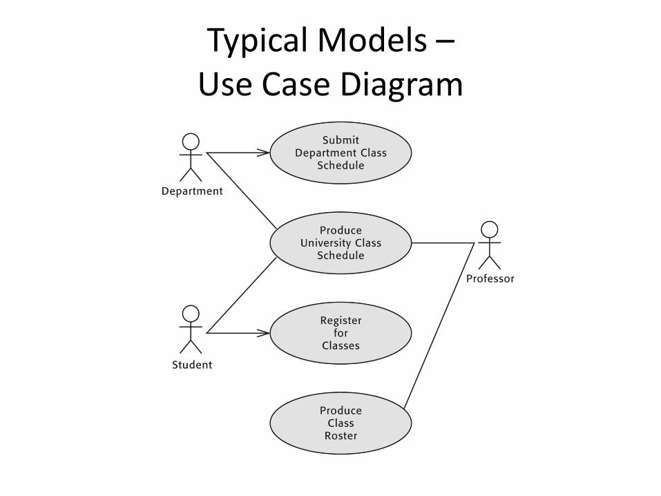
Typical Models –Use Case Diagram
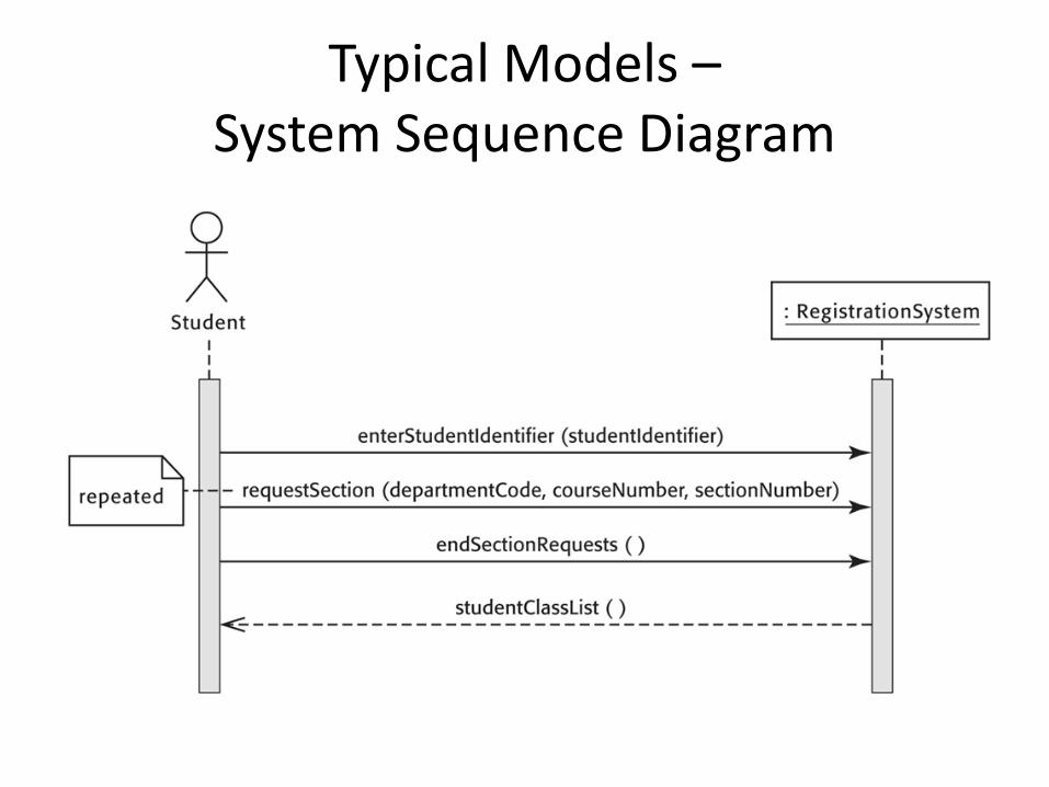
Typical Models –System Sequence Diagram
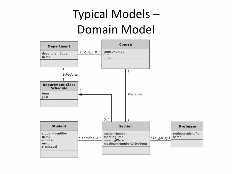
Typical Models –Domain Model
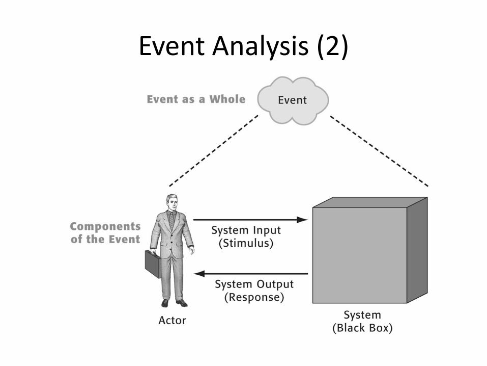
Event-Driven Systems
Event analysis takes a stimulus-response perspective –
• The system does nothing until it is triggered by an event.
• When an event occurs, the system responds as completely as possible.
• After the response is complete, the system waits until another event occurs.
Events
An event is an occurrence which takes place at a specific time and initiates or triggers a predetermined response from the system.
• An external event is an event which occurs outside the system boundary.
• An internal event is an event which occurs inside the system boundary.
• A temporal event is an event which occurs at a prespecified time.
Event Analysis
Event analysis creates a system description by identifying:
1. The events to which the system is expected to respond
2. The incoming message (event flow or data flow) associated with each event
3. The desired response 4. The actions or behaviors required to
generate the response for each stimulus
Event Analysis (2)
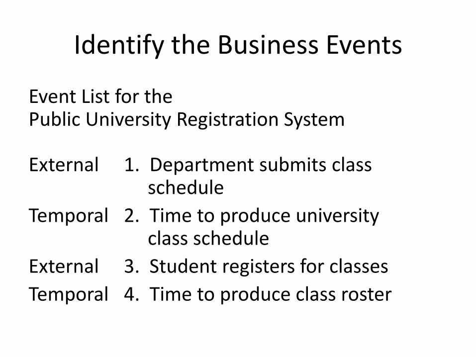
Identify the Business Events
Event List for the Public University Registration System
External 1. Department submits classschedule
Temporal 2. Time to produce university class schedule
External 3. Student registers for classesTemporal 4. Time to produce class roster

Hints About Event Analysis
• Ignore the technology of implementation –build an essential event model.
• Model the system’s complete response – don’t split a single event into fragments.
• Isolate individual events –don’t combine events if the system must wait in between them.
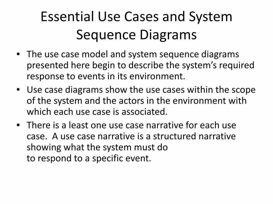
Essential Use Cases and System Sequence Diagrams
• The use case model and system sequence diagrams presented here begin to describe the system’s required response to events in its environment.
• Use case diagrams show the use cases within the scope of the system and the actors in the environment with which each use case is associated.
• There is a least one use case narrative for each use case. A use case narrative is a structured narrative showing what the system must do to respond to a specific event.
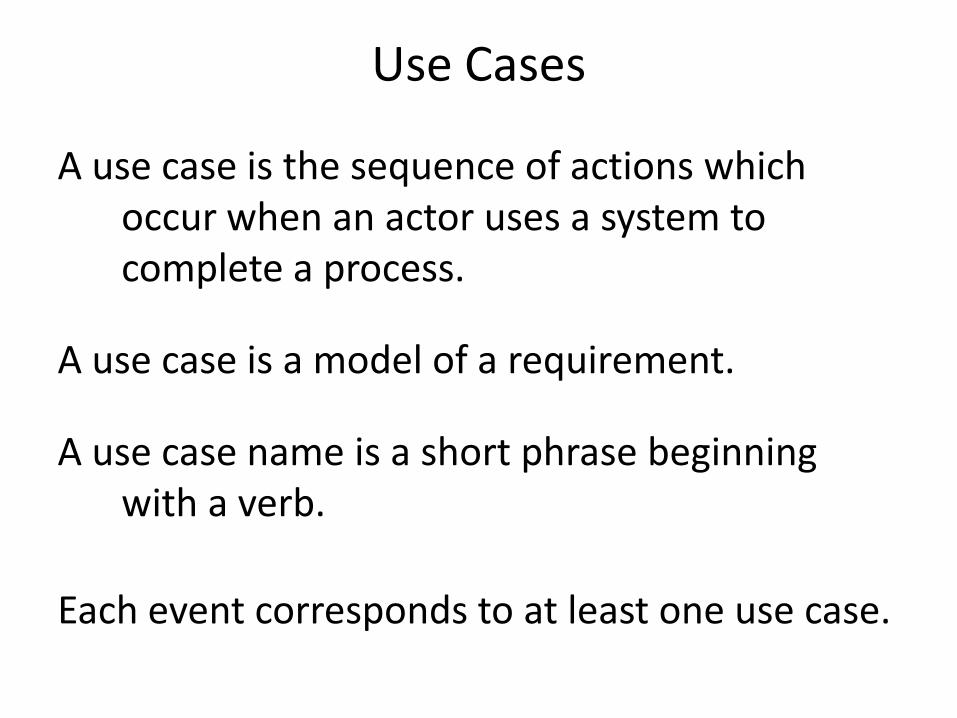
Use Cases
A use case is the sequence of actions which occur when an actor uses a system to complete a process.
A use case is a model of a requirement.
A use case name is a short phrase beginning with a verb.
Each event corresponds to at least one use case.
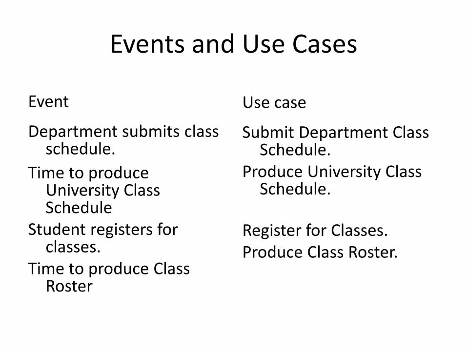
Events and Use Cases
Event
Department submits class schedule.
Time to produce University Class Schedule
Student registers for classes.
Time to produce Class Roster
Use case
Submit Department Class Schedule.
Produce University Class Schedule.
Register for Classes.Produce Class Roster.

Identifying Actors
An actor is a person, organization, or system which interacts with a system by sending messages to the system or receiving messages from the system.
Actors play roles with respect to the system.
The actors were identified during event analysis.


![Object-oriented Programming with PHP · Object-oriented Programming with PHP [2 ] Object-oriented programming Object-oriented programming is a popular programming paradigm where concepts](https://static.fdocuments.in/doc/165x107/5e1bb46bfe726d12f8517bf0/object-oriented-programming-with-php-object-oriented-programming-with-php-2-object-oriented.jpg)