Module 3 Object Oriented Data Models Object Oriented notations
Upload
marion-smithCategory
view
242download
0
Object-Oriented Analysis and Design 1Mira Balaban & Arnon Sturm
Object-Oriented Analysis Object-Oriented Analysis and Designand Design
Session 4: Object-Oriented Software Construction
Object-Oriented Analysis and DesignMira Balaban & Arnon Sturm 2
Goal
This session introduces the object-oriented software development process.(Larman: Applying UML and Patterns).
Object-Oriented Analysis and DesignMira Balaban & Arnon Sturm 3
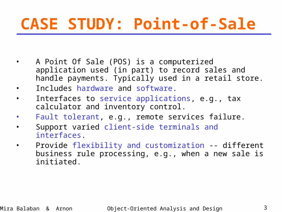
• A Point Of Sale (POS) is a computerized application used (in part) to record sales and handle payments. Typically used in a retail store.
• Includes hardware and software.• Interfaces to service applications, e.g., tax calculator and
inventory control.• Fault tolerant, e.g., remote services failure.• Support varied client-side terminals and interfaces.• Provide flexibility and customization -- different business
rule processing, e.g., when a new sale is initiated.
CASE STUDY: Point-of-Sale
Object-Oriented Analysis and DesignMira Balaban & Arnon Sturm 4
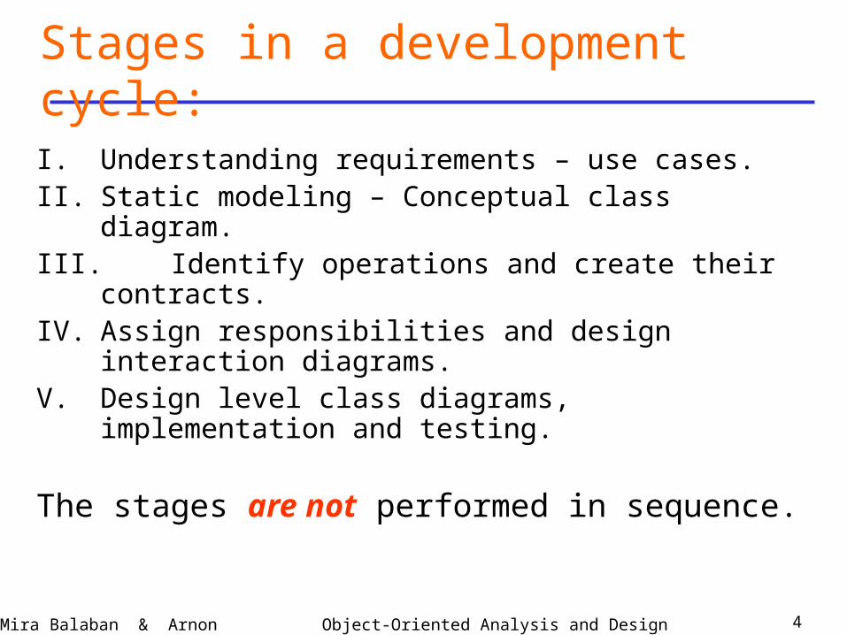
I. Understanding requirements – use cases.II. Static modeling – Conceptual class diagram.III. Identify operations and create their contracts.IV. Assign responsibilities and design interaction
diagrams. V. Design level class diagrams, implementation and
testing.
The stages are not performed in sequence.
Stages in a development cycle:

Object-Oriented Analysis and DesignMira Balaban & Arnon Sturm 5
• A use case is a narrative document – a story -- that describes the sequence of events of an actor using a system to complete a process.
• A use case describes a typical interaction between an external entity (the actor – person, system, organization) to the system.
• A use case describes multiple scenarios.• A scenario is a single path through the use case.• A use case depends on partial understanding of
the requirements.• Use cases can be found by looking for their
initiator actors.
I. Understanding requirements – Use Cases
Object-Oriented Analysis and DesignMira Balaban & Arnon Sturm 6
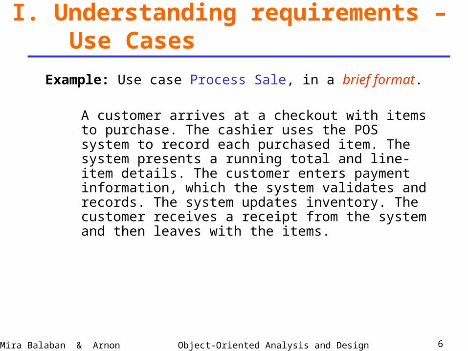
Example: Use case Process Sale, in a brief format.
A customer arrives at a checkout with items to purchase. The cashier uses the POS system to record each purchased item. The system presents a running total and line-item details. The customer enters payment information, which the system validates and records. The system updates inventory. The customer receives a receipt from the system and then leaves with the items.
I. Understanding requirements – Use Cases
Object-Oriented Analysis and DesignMira Balaban & Arnon Sturm 7
I. Understanding requirements – Use Cases
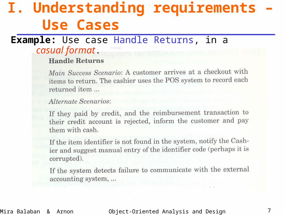
Example: Use case Handle Returns, in a casual format.
Object-Oriented Analysis and DesignMira Balaban & Arnon Sturm 8
I. Understanding requirements – Use Cases
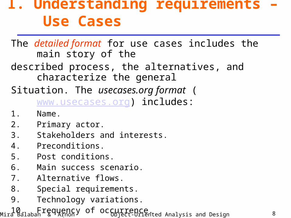
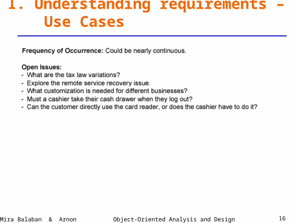
The detailed format for use cases includes the main story of the described process, the alternatives, and characterize the generalSituation. The usecases.org format (www.usecases.org) includes:1. Name.2. Primary actor.3. Stakeholders and interests.4. Preconditions.5. Post conditions.6. Main success scenario.7. Alternative flows.8. Special requirements.9. Technology variations.10. Frequency of occurrence.11. Open issues.
Object-Oriented Analysis and DesignMira Balaban & Arnon Sturm 9
I. Understanding requirements – Use Cases
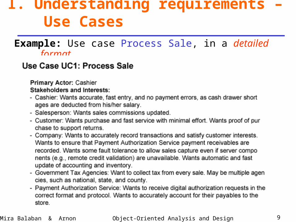
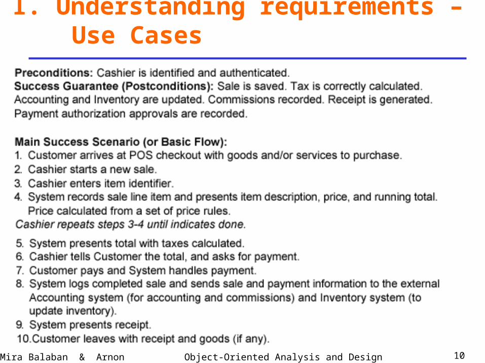
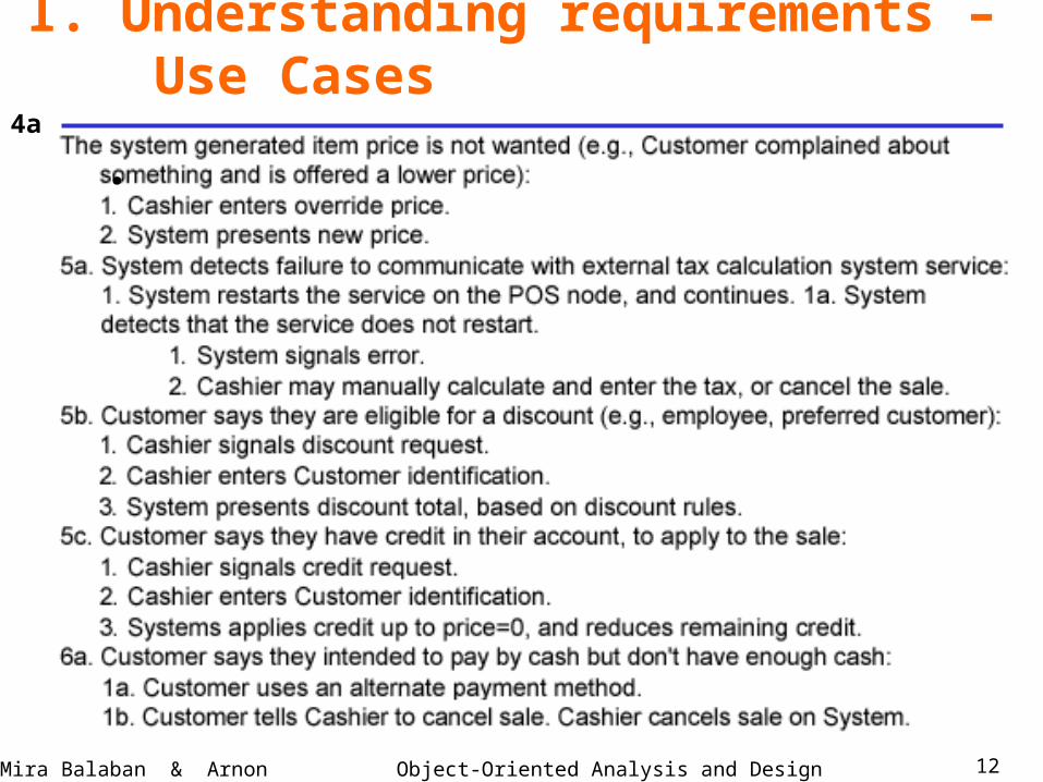
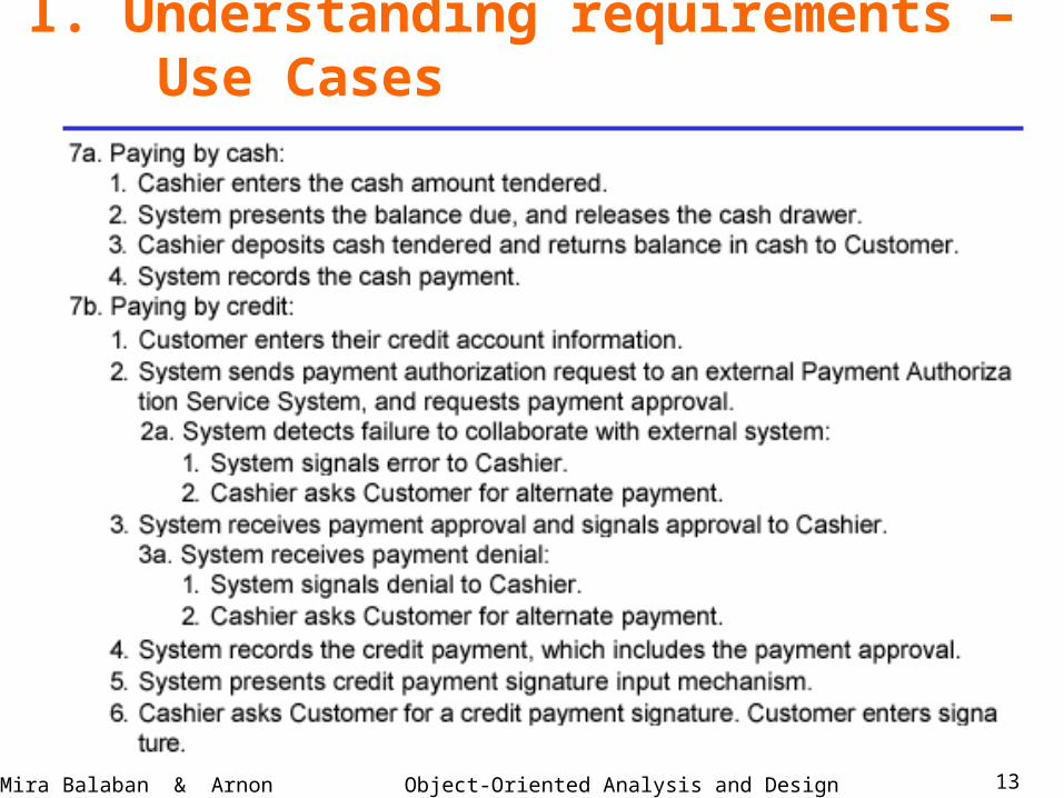
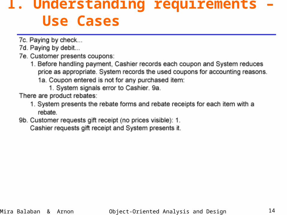
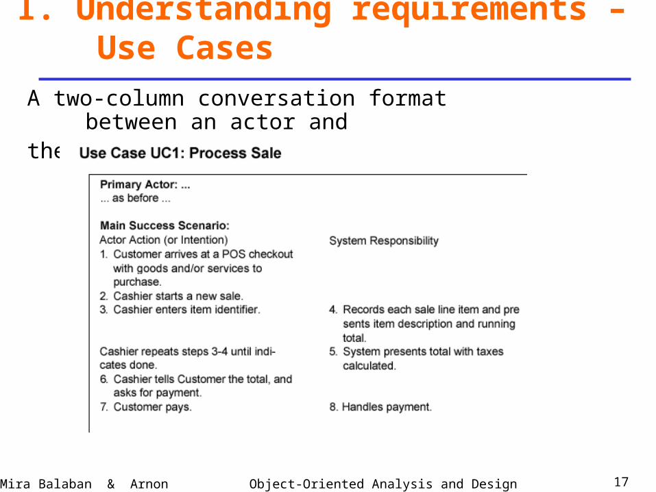
Example: Use case Process Sale, in a detailed format.
Object-Oriented Analysis and DesignMira Balaban & Arnon Sturm 10
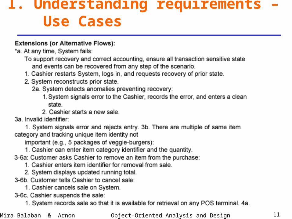
I. Understanding requirements – Use Cases
Object-Oriented Analysis and DesignMira Balaban & Arnon Sturm 11
I. Understanding requirements – Use Cases
Object-Oriented Analysis and DesignMira Balaban & Arnon Sturm 12
I. Understanding requirements – Use Cases
4a.
Object-Oriented Analysis and DesignMira Balaban & Arnon Sturm 13
I. Understanding requirements – Use Cases
Object-Oriented Analysis and DesignMira Balaban & Arnon Sturm 14
I. Understanding requirements – Use Cases

Object-Oriented Analysis and DesignMira Balaban & Arnon Sturm 15
I. Understanding requirements – Use Cases
Object-Oriented Analysis and DesignMira Balaban & Arnon Sturm 16
I. Understanding requirements – Use Cases
Object-Oriented Analysis and DesignMira Balaban & Arnon Sturm 17
I. Understanding requirements – Use Cases
A two-column conversation format between an actor andthe system:
Object-Oriented Analysis and DesignMira Balaban & Arnon Sturm 18
I. Understanding requirements – Use Cases
What use cases are not ?A common mistake about use cases:
A use case is a relatively large, end-to-end
process description, that typically includes
many steps or transactions; it is not normally
an individual step or activity.
For example: “print the receipt” is a step,
system function, not a use case.
Object-Oriented Analysis and DesignMira Balaban & Arnon Sturm 19
I. Understanding requirements – Use Cases
Finding use cases:• Choose system boundary: Decide what is
outside the system.For POS – cashier, payment authorization, inventory control, …
• Identify primary actors.• Identify actor goals.• Define use cases that satisfy actor goals.
Object-Oriented Analysis and DesignMira Balaban & Arnon Sturm 20
I. Understanding requirements – Use Cases
Essential versus real use cases:• Essential – conceptual specification of expanded
use cases.
The customer identifies himself/herself.
• Real – Concrete specification of the process.
The customer inserts his/her credit card and
types the code.
Only in design level.
Object-Oriented Analysis and DesignMira Balaban & Arnon Sturm 21
I. Understanding requirements – Use Cases
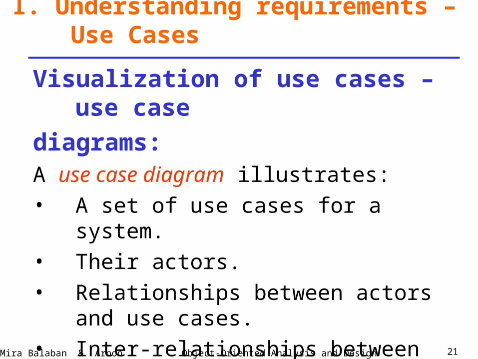
Visualization of use cases – use case
diagrams:A use case diagram illustrates:
• A set of use cases for a system.
• Their actors.
• Relationships between actors and use cases.
• Inter-relationships between use cases.
Object-Oriented Analysis and DesignMira Balaban & Arnon Sturm 22
I. Understanding requirements – Use Cases
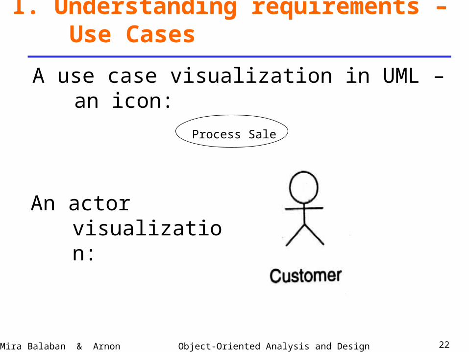
A use case visualization in UML – an icon:
An actor visualization:
Process Sale
Object-Oriented Analysis and DesignMira Balaban & Arnon Sturm 23
I. Understanding requirements – Use Cases
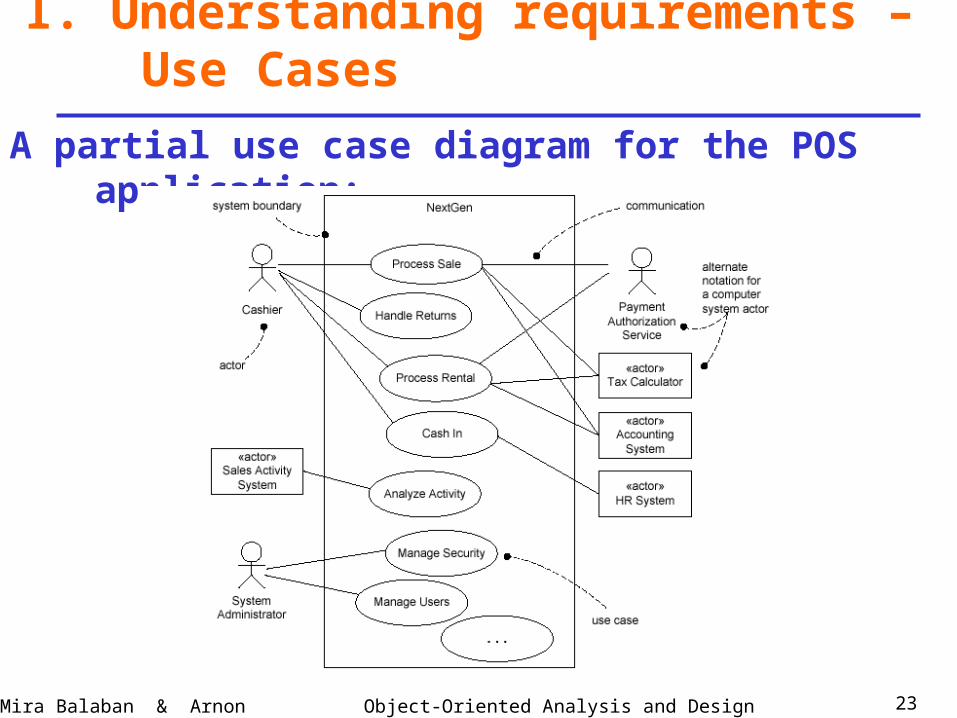
A partial use case diagram for the POS application:
Object-Oriented Analysis and DesignMira Balaban & Arnon Sturm 24
I. Understanding requirements – Use Cases
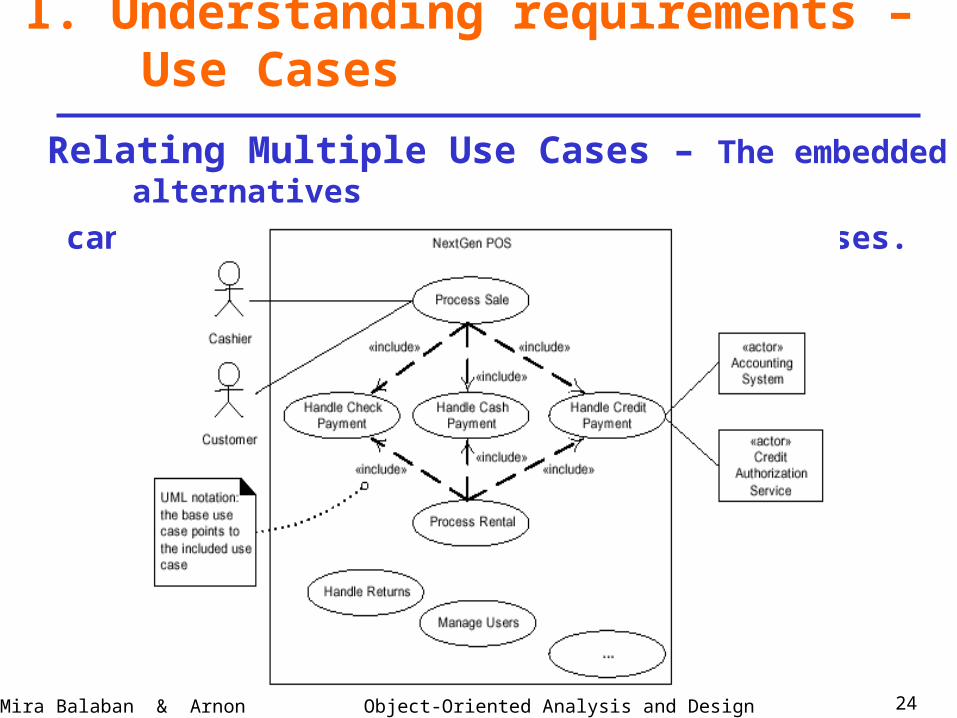
Relating Multiple Use Cases – The embedded alternatives
can be singled out as independent use cases.
Object-Oriented Analysis and DesignMira Balaban & Arnon Sturm 25
I. Understanding requirements – Use Cases
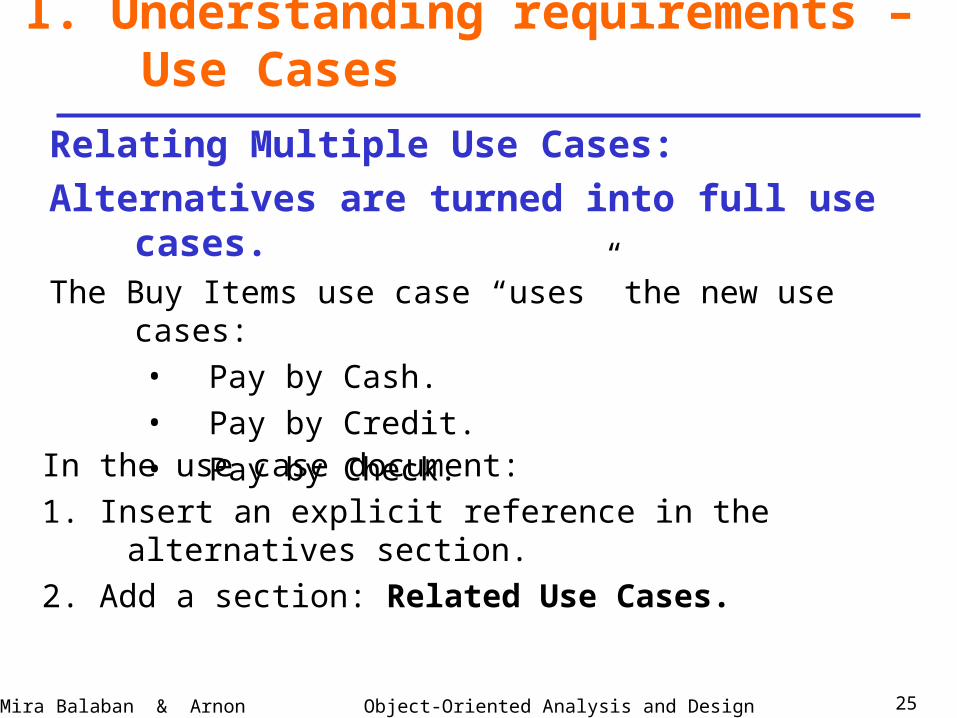
Relating Multiple Use Cases:
Alternatives are turned into full use cases. The Buy Items use case “uses” the new use cases:
• Pay by Cash.
• Pay by Credit.
• Pay by Check.
In the use case document:
1. Insert an explicit reference in the alternatives section.
2. Add a section: Related Use Cases.
Object-Oriented Analysis and DesignMira Balaban & Arnon Sturm 26
I. Understanding requirements – Use Cases
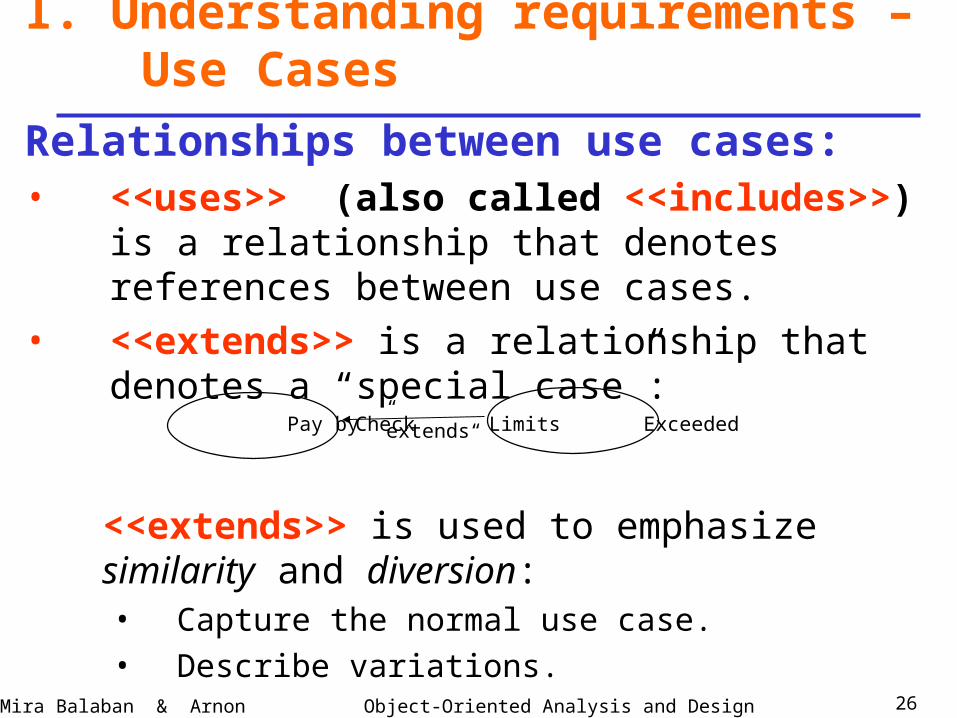
Relationships between use cases:• <<uses>> (also called <<includes>>) is a
relationship that denotes references between use cases.
• <<extends>> is a relationship that denotes a “special case”:
<<extends>> is used to emphasize similarity and diversion:• Capture the normal use case.
• Describe variations.
Limits ExceededPay by Check “extends”
Object-Oriented Analysis and DesignMira Balaban & Arnon Sturm 27
I. Understanding requirements – Use Cases
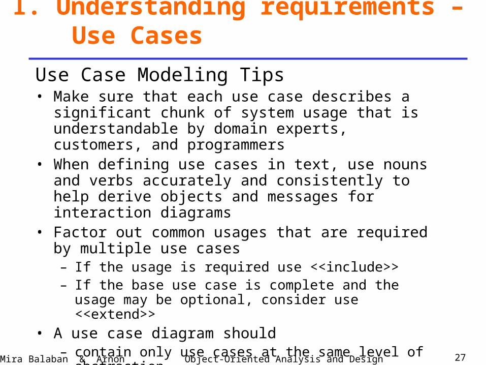
Use Case Modeling Tips• Make sure that each use case describes a significant chunk of
system usage that is understandable by domain experts, customers, and programmers
• When defining use cases in text, use nouns and verbs accurately and consistently to help derive objects and messages for interaction diagrams
• Factor out common usages that are required by multiple use cases– If the usage is required use <<include>>– If the base use case is complete and the usage may be optional,
consider use <<extend>>
• A use case diagram should– contain only use cases at the same level of abstraction– include only actors who are required
• Complexity management

Object-Oriented Analysis and DesignMira Balaban & Arnon Sturm 28
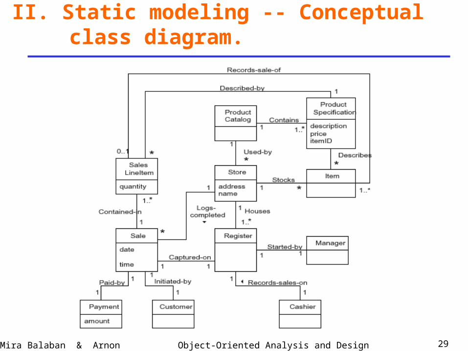
• Described by class diagrams.• Iterative development.
In the analysis stage:• White diagrams: Classes, Associations, Multiplicity constraints. • Add attributes, Qualifiers.• Advanced features: Generalization (sub-typing), Aggregation, Association
classes, packaging.
In the design stage -- add:• Navigability (directions to associations).• Types for attributes.• Methods.
II. Static modeling -- Conceptual class diagram.
Object-Oriented Analysis and DesignMira Balaban & Arnon Sturm 29
II. Static modeling -- Conceptual class diagram.
Object-Oriented Analysis and DesignMira Balaban & Arnon Sturm 30
Steps:1. Identify system events that trigger system
operations.
2. Create contracts for the identified operations.
III. Identify operations and create their contracts
Object-Oriented Analysis and DesignMira Balaban & Arnon Sturm 31
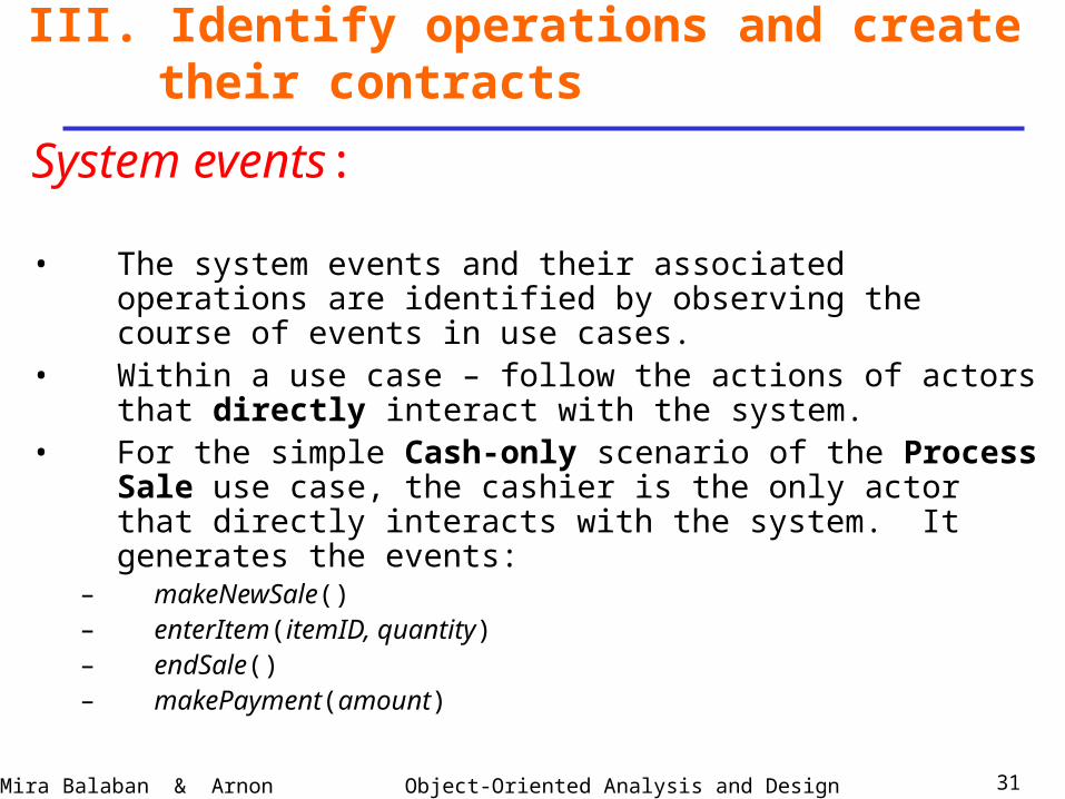
System events:
• The system events and their associated operations are identified by observing the course of events in use cases.
• Within a use case – follow the actions of actors that directly interact with the system.
• For the simple Cash-only scenario of the Process Sale use case, the cashier is the only actor that directly interacts with the system. It generates the events:
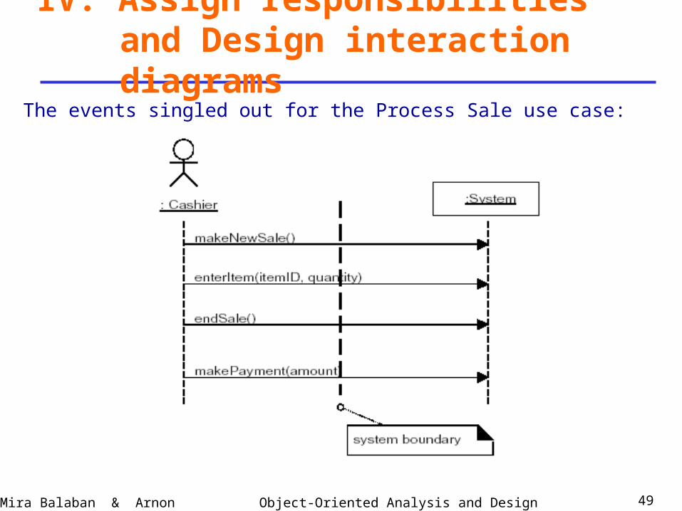
– makeNewSale()– enterItem(itemID, quantity)– endSale()– makePayment(amount)
III. Identify operations and create their contracts
Object-Oriented Analysis and DesignMira Balaban & Arnon Sturm 32
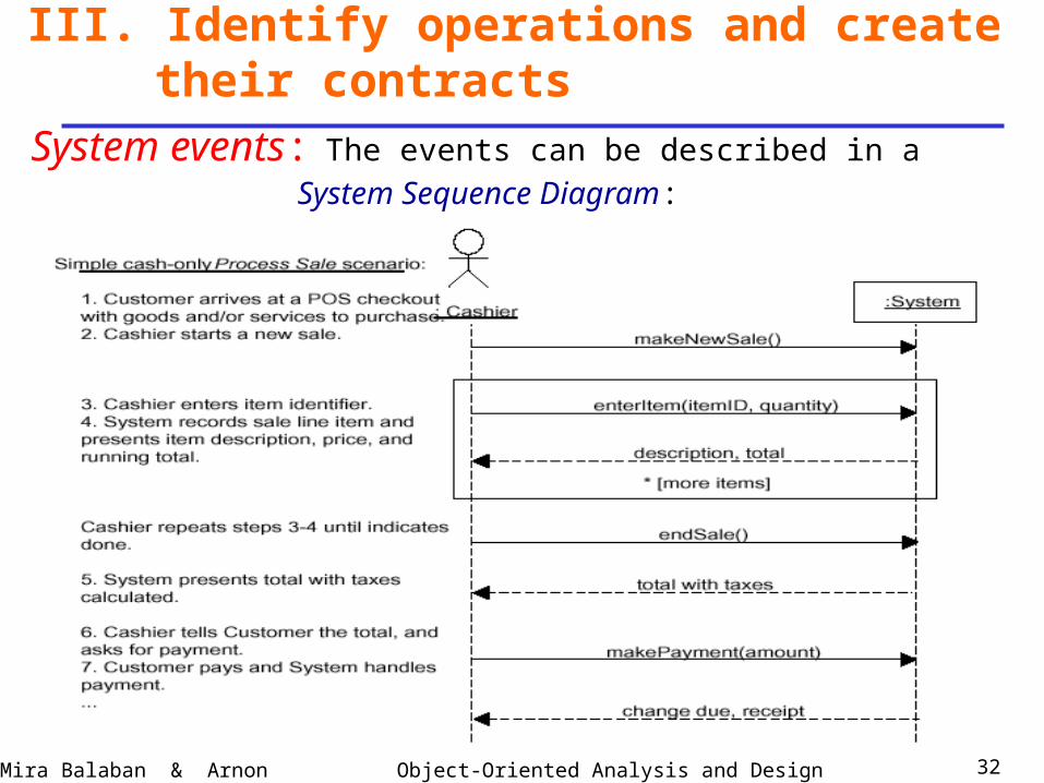
System events: The events can be described in a
System Sequence Diagram:
III. Identify operations and create their contracts
Object-Oriented Analysis and DesignMira Balaban & Arnon Sturm 33
System sequence diagrams are important!
1. They serve for connecting the application logic layerto other layers:
– If the actor is human – connection to the presentation
layer.– If the actor is an external service – application interface.
2. They serve for implementing the use case scenarios.
III. Identify operations and create their contracts
Object-Oriented Analysis and DesignMira Balaban & Arnon Sturm 34
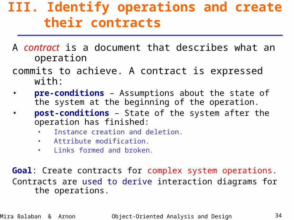
A contract is a document that describes what an operationcommits to achieve. A contract is expressed with:• pre-conditions – Assumptions about the state of the system at
the beginning of the operation.• post-conditions – State of the system after the operation has
finished:• Instance creation and deletion.• Attribute modification.• Links formed and broken.
Goal: Create contracts for complex system operations.Contracts are used to derive interaction diagrams for the operations.
III. Identify operations and create their contracts
Object-Oriented Analysis and DesignMira Balaban & Arnon Sturm 35
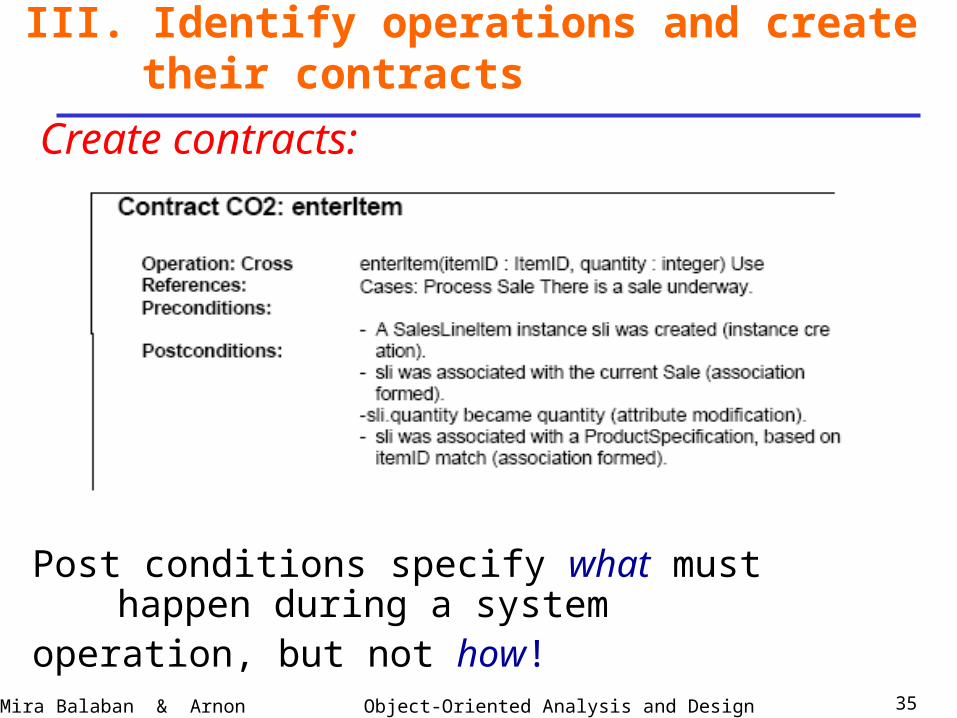
Create contracts:
III. Identify operations and create their contracts
Post conditions specify what must happen during a systemoperation, but not how!
Object-Oriented Analysis and DesignMira Balaban & Arnon Sturm 36
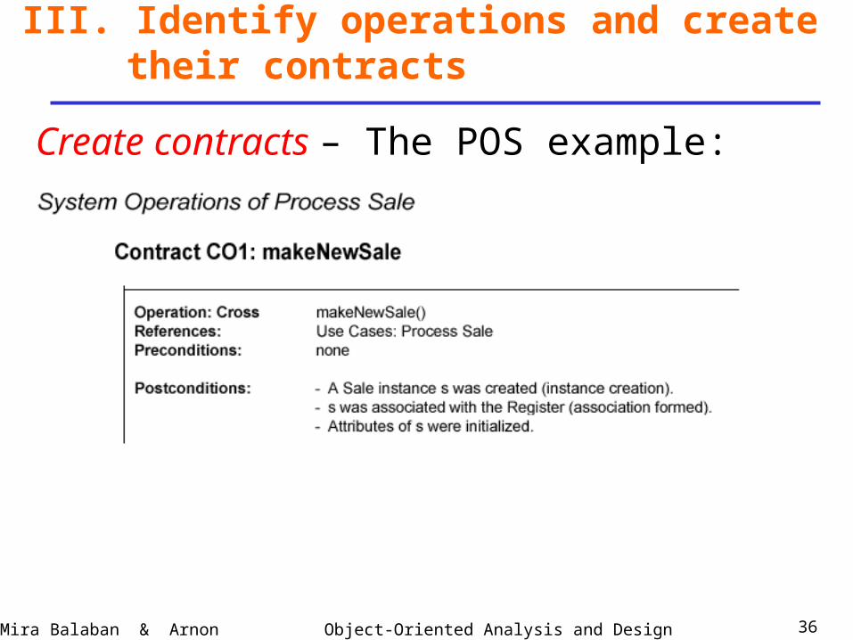
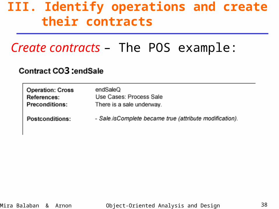
Create contracts – The POS example:
III. Identify operations and create their contracts
Object-Oriented Analysis and DesignMira Balaban & Arnon Sturm 37
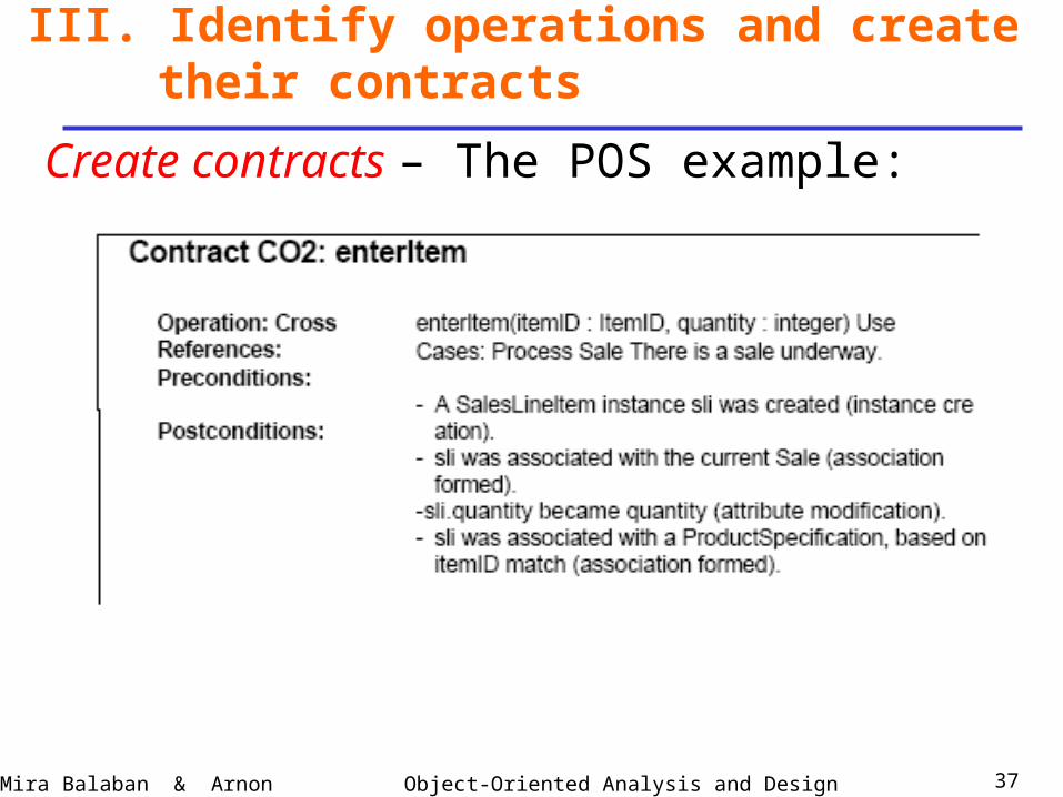
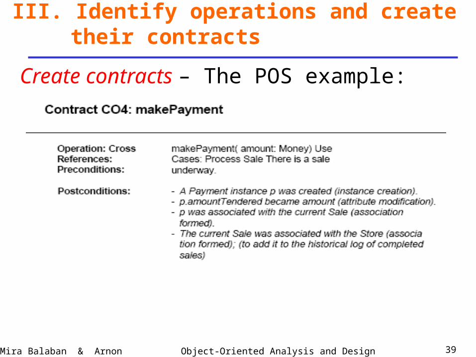
Create contracts – The POS example:
III. Identify operations and create their contracts
Object-Oriented Analysis and DesignMira Balaban & Arnon Sturm 38
Create contracts – The POS example:
III. Identify operations and create their contracts
3:
Object-Oriented Analysis and DesignMira Balaban & Arnon Sturm 39
Create contracts – The POS example:
III. Identify operations and create their contracts
Object-Oriented Analysis and DesignMira Balaban & Arnon Sturm 40
Create contracts:1. Contracts might imply changes to the static domain
model:For example, add a boolean isComplete attribute to the Sale class, to mark the end of a sale.
2. Contracts for operations can be expressed in OCL.Preconditions and postconditions are written as OCL constraints in the context of the contract operation.
III. Identify operations and create their contracts
Object-Oriented Analysis and DesignMira Balaban & Arnon Sturm 41
Two interwoven tasks:
1. Impose responsibilities – assign operations to classes.
2. Design operations – sequence/collaboration diagrams.
IV. Assign responsibilities and Design interaction diagrams
Object-Oriented Analysis and DesignMira Balaban & Arnon Sturm 42
Input to this stage: A contract built for a system operation.
Output of this stage: An interaction diagram.
The design is based on Principles (Patterns) for Assigning
Responsibilities –
GRASP (General Responsibility Assignment Software Patterns).
IV. Assign responsibilities and Design interaction diagrams
Object-Oriented Analysis and DesignMira Balaban & Arnon Sturm 43
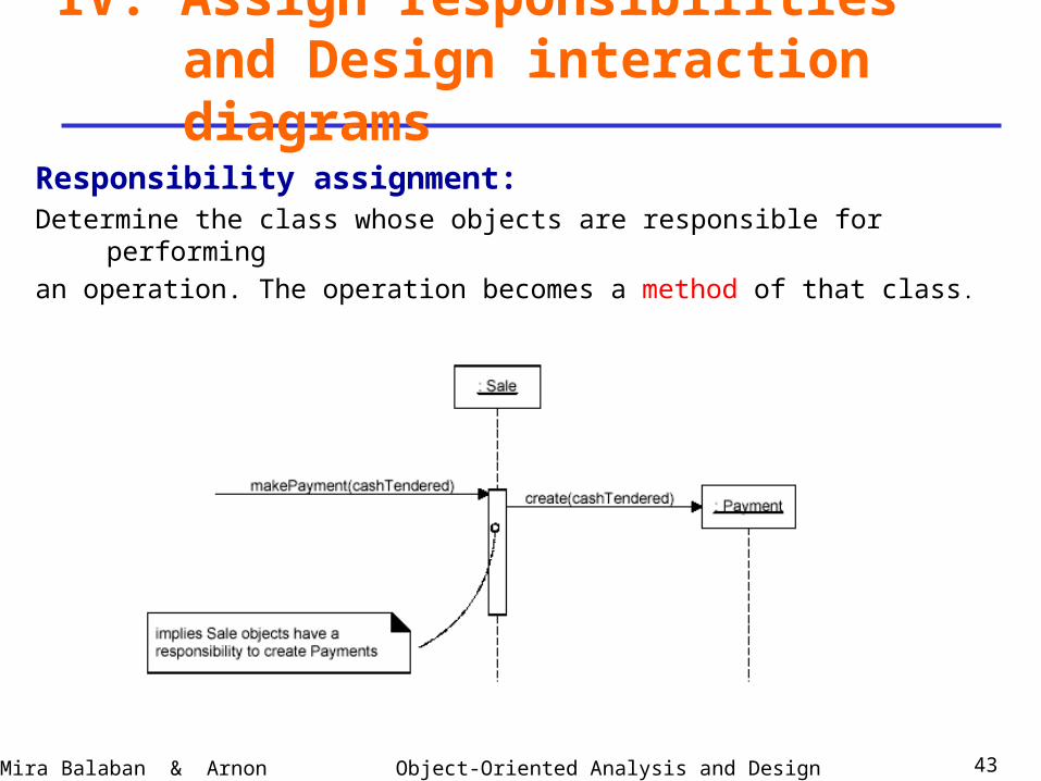
Responsibility assignment:Determine the class whose objects are responsible for performing
an operation. The operation becomes a method of that class.
IV. Assign responsibilities and Design interaction diagrams
Object-Oriented Analysis and DesignMira Balaban & Arnon Sturm 44
Responsibility assignment - Based on patterns
IV. Assign responsibilities and Design interaction diagrams
A pattern is a named problem/solution pair that can be applied in
new context, with advice on how to apply it in novel situations
and discussion of its trade-offs.
• Patterns exist in various paradigms.
• In Software Engineering they are idioms for software creation.
• They are expressed in narrative documents, programming code and more quasi formal languages like UML diagrams.
Object-Oriented Analysis and DesignMira Balaban & Arnon Sturm 45
Responsibility assignment - Based on patterns
IV. Assign responsibilities and Design interaction diagrams
Major GRASP patterns:
• Information Expert
• Creator
• High Cohesion
• Low Coupling
• Controller
They address very basic, common questions and fundamental design
issues.
Object-Oriented Analysis and DesignMira Balaban & Arnon Sturm 46
Responsibility assignment - Based on patterns
IV. Assign responsibilities and Design interaction diagrams
GRASP patterns are introduced as required for the design of
interaction diagrams for the POS problem.
We consider 2 use cases:
• Process Sale.
• Start-up.
Object-Oriented Analysis and DesignMira Balaban & Arnon Sturm 47
Reminder: The overall steps towards the development of
interaction diagrams:
Use cases + conceptual model
Identify system events (operations) – use SSDs.
Build contracts
Interaction diagrams.
IV. Assign responsibilities and Design interaction diagrams
Object-Oriented Analysis and DesignMira Balaban & Arnon Sturm 48
Importance of interaction diagrams:• Express decisions about responsibilities for operations.• Complement the conceptual model.• The conceptual model and the interaction diagrams are
the most important artifacts created in the object-oriented analysis and design.
• Good quality interaction diagrams express codified patterns, principles and idioms.
IV. Assign responsibilities and Design interaction diagrams
Object-Oriented Analysis and DesignMira Balaban & Arnon Sturm 49
The events singled out for the Process Sale use case:
IV. Assign responsibilities and Design interaction diagrams
Object-Oriented Analysis and DesignMira Balaban & Arnon Sturm 50
First question:
Which class is responsible for each operation?
An advice is given by the Controller pattern.
Its problem is:
“Who should be responsible for handling an input system event?”
IV. Assign responsibilities and Design interaction diagrams
Object-Oriented Analysis and DesignMira Balaban & Arnon Sturm 51
The Controller PatternProblem: Who should be responsible for handling a
system event?• The controller pattern provides an advice for
selecting a controller for a system event – an operation triggered by an external actor.
• A controller is a domain layer object responsible for handling a system event. A controller defines a method for a system operation.
IV. Assign responsibilities and Design interaction diagrams
Object-Oriented Analysis and DesignMira Balaban & Arnon Sturm 52
The Controller PatternSolution: Assign the responsibility for receiving or handling a system event message to a class representing one of the following choices:• Facade controller -- Represents the overall system, device, or
subsystem.• Use case controller -- Represents a use case scenario within
which the system event occurs.Common name: <UseCaseName>Handler.
• Role controller – Represents something that can be involved in the task.
IV. Assign responsibilities and Design interaction diagrams
Object-Oriented Analysis and DesignMira Balaban & Arnon Sturm 53
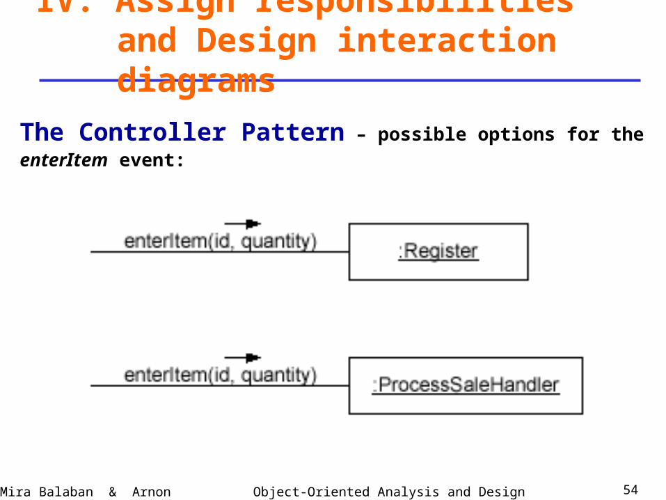
The Controller PatternFor the enterItem event in the Process-sale use case:• Possible facade controllers are:
– Register – represents the overall system.– Store – represents the overall organization.
• Possible role controller is Cashier – represents something that can be involved in the task.
• Use case controller: ProcessSaleHandler– its instances represent sessions (conversations) with an actor.
– In that case – all system events in the same use case are handled by the same controller.
IV. Assign responsibilities and Design interaction diagrams
Object-Oriented Analysis and DesignMira Balaban & Arnon Sturm 54
The Controller Pattern – possible options for the
enterItem event:
IV. Assign responsibilities and Design interaction diagrams
Object-Oriented Analysis and DesignMira Balaban & Arnon Sturm 55
The Controller PatternA facade controller is a good option if there are only few
system events.
Otherwise – the façade controller takes too many
Responsibilities
It becomes incohesive.
IV. Assign responsibilities and Design interaction diagrams
Object-Oriented Analysis and DesignMira Balaban & Arnon Sturm 56
The Controller PatternDecision among various options suggested by a pattern:
Use the general criteria:
– High cohesion.
– Low coupling.
IV. Assign responsibilities and Design interaction diagrams
Object-Oriented Analysis and DesignMira Balaban & Arnon Sturm 57
The Controller PatternFor the events of the Process Sale use case:
Possible façade controllers are:
Register, Store.
Based on cohesion select Register.
IV. Assign responsibilities and Design interaction diagrams
Object-Oriented Analysis and DesignMira Balaban & Arnon Sturm 58
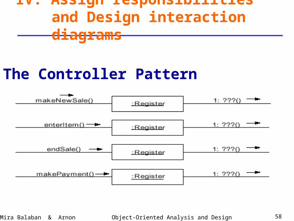
The Controller Pattern
IV. Assign responsibilities and Design interaction diagrams
Object-Oriented Analysis and DesignMira Balaban & Arnon Sturm 59
Design interaction diagrams –Use contracts built for the system events that are singledout for a use case.In each contract – use the post conditions section!For the Process Sale use case --
4 interaction diagrams for the events:makeNewSale, enterItem, endSale, makePayment.
IV. Assign responsibilities and Design interaction diagrams
Object-Oriented Analysis and DesignMira Balaban & Arnon Sturm 60
Design interaction diagrams –System events:
1. makeNewSale.
2. enterItem.
3. endSale.
4. Sale – getTotal: Presentation requirement.
5. makePayment.
6. Payment – getBalance: Presentation requirement.
7. startUp.
IV. Assign responsibilities and Design interaction diagrams
Object-Oriented Analysis and DesignMira Balaban & Arnon Sturm 61
IV. Assign responsibilities and Design interaction diagrams
Object-Oriented Analysis and DesignMira Balaban & Arnon Sturm 62
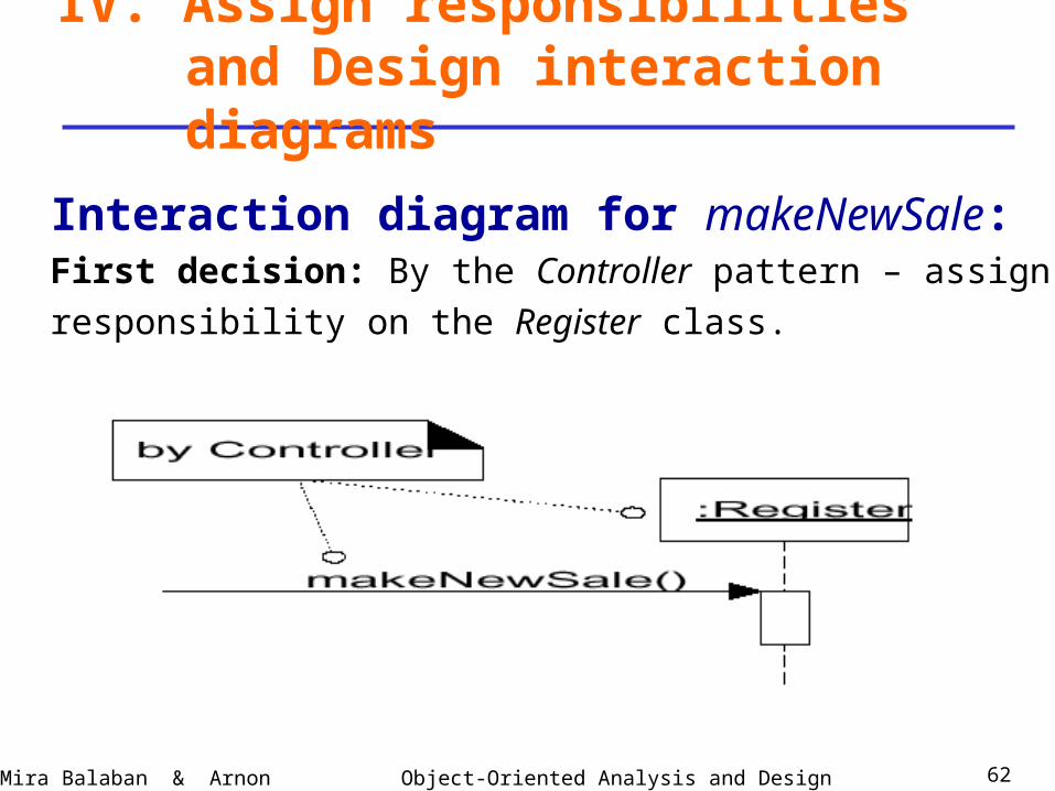
Interaction diagram for makeNewSale:First decision: By the Controller pattern – assign
responsibility on the Register class.
IV. Assign responsibilities and Design interaction diagrams
Object-Oriented Analysis and DesignMira Balaban & Arnon Sturm 63
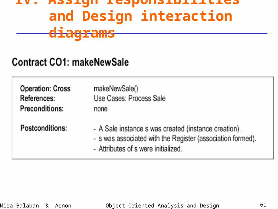
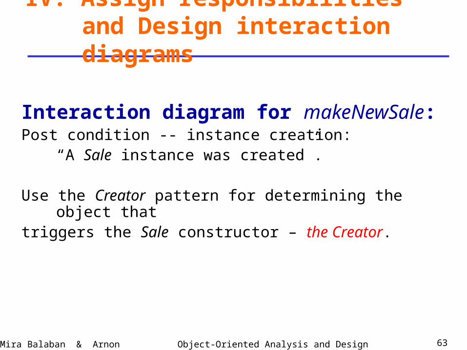
Interaction diagram for makeNewSale:Post condition -- instance creation:
“A Sale instance was created”.
Use the Creator pattern for determining the object thattriggers the Sale constructor – the Creator.
IV. Assign responsibilities and Design interaction diagrams
Object-Oriented Analysis and DesignMira Balaban & Arnon Sturm 64
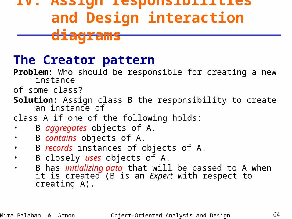
The Creator patternProblem: Who should be responsible for creating a new instanceof some class?Solution: Assign class B the responsibility to create an instance ofclass A if one of the following holds:• B aggregates objects of A.• B contains objects of A.• B records instances of objects of A.• B closely uses objects of A.• B has initializing data that will be passed to A when it is
created (B is an Expert with respect to creating A).
IV. Assign responsibilities and Design interaction diagrams
Object-Oriented Analysis and DesignMira Balaban & Arnon Sturm 65
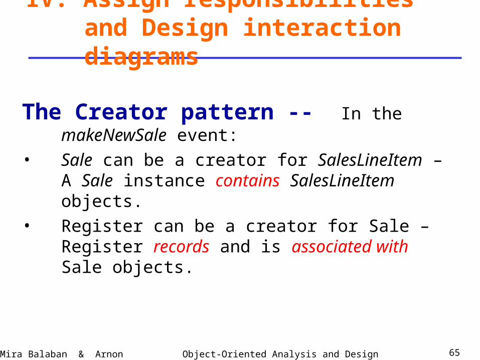
The Creator pattern -- In the makeNewSale event:
• Sale can be a creator for SalesLineItem – A Sale instance contains SalesLineItem objects.
• Register can be a creator for Sale – Register records and is associated with Sale objects.
IV. Assign responsibilities and Design interaction diagrams
Object-Oriented Analysis and DesignMira Balaban & Arnon Sturm 66
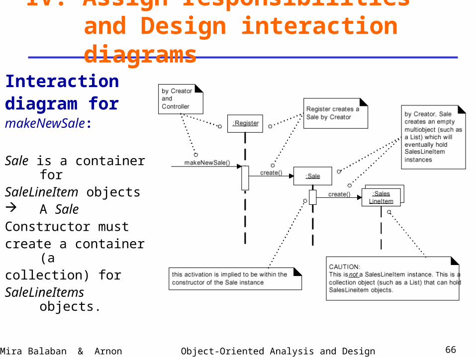
Interactiondiagram for makeNewSale:
Sale is a container forSaleLineItem objects A SaleConstructor mustcreate a container (acollection) forSaleLineItems objects.
IV. Assign responsibilities and Design interaction diagrams

Object-Oriented Analysis and DesignMira Balaban & Arnon Sturm 67
Design interaction diagrams –System events:
1. makeNewSale.
2. enterItem.
3. endSale.
4. Sale – getTotal: Presentation requirement.
5. makePayment.
6. Payment – getBalance: Presentation requirement.
7. startUp.
IV. Assign responsibilities and Design interaction diagrams
Object-Oriented Analysis and DesignMira Balaban & Arnon Sturm 68
IV. Assign responsibilities and Design interaction diagrams
Object-Oriented Analysis and DesignMira Balaban & Arnon Sturm 69
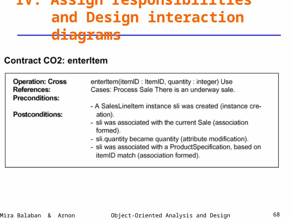
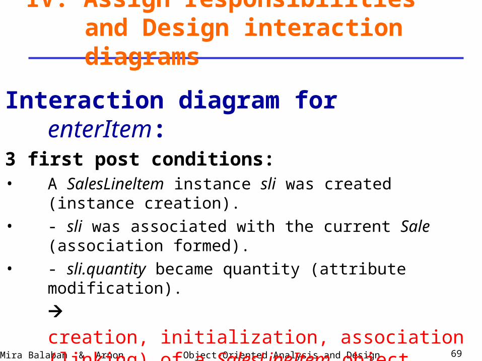
Interaction diagram for enterItem:3 first post conditions:• A SalesLineltem instance sli was created (instance creation).
• - sli was associated with the current Sale (association formed).
• - sli.quantity became quantity (attribute modification).
creation, initialization, association (linking) of a SalesLineItem object.
IV. Assign responsibilities and Design interaction diagrams
Object-Oriented Analysis and DesignMira Balaban & Arnon Sturm 70
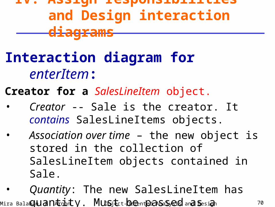
Interaction diagram for enterItem:Creator for a SalesLineItem object.• Creator -- Sale is the creator. It contains
SalesLineItems objects.• Association over time – the new object is stored in the
collection of SalesLineItem objects contained in Sale.• Quantity: The new SalesLineItem has quantity. Must be
passed as a parameter.
IV. Assign responsibilities and Design interaction diagrams
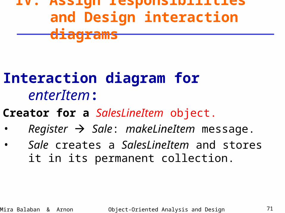
Object-Oriented Analysis and DesignMira Balaban & Arnon Sturm 71
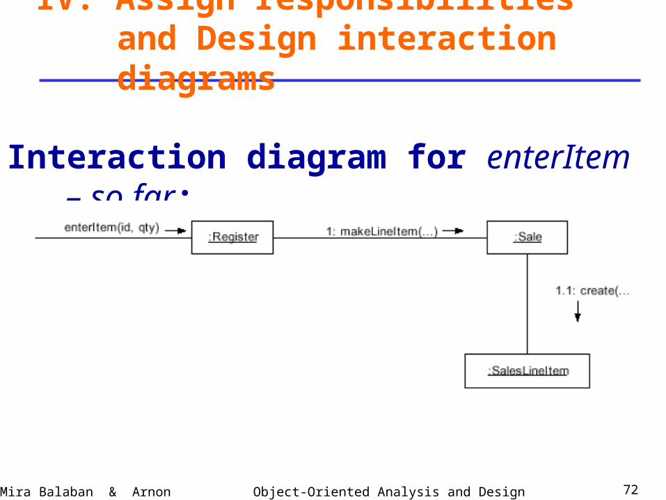
Interaction diagram for enterItem:Creator for a SalesLineItem object.• Register Sale: makeLineItem message.• Sale creates a SalesLineItem and stores it in its
permanent collection.
IV. Assign responsibilities and Design interaction diagrams
Object-Oriented Analysis and DesignMira Balaban & Arnon Sturm 72
Interaction diagram for enterItem – so far:
IV. Assign responsibilities and Design interaction diagrams
Object-Oriented Analysis and DesignMira Balaban & Arnon Sturm 73
Interaction diagram for enterItem:
IV. Assign responsibilities and Design interaction diagrams
Parameters to makeLineItem:
First parameter: quantity – recoded by SalesLineItem.
4th postcondition:
sli was associated with a ProductSpecification, based
on itemID match.
Second parameter: productSpecification – matches the ID
code.
Object-Oriented Analysis and DesignMira Balaban & Arnon Sturm 74
Interaction diagram for enterItem:
IV. Assign responsibilities and Design interaction diagrams
Finding a productSpecification based on an ID code.
Task: Retrieve a ProductSpecification based on an ID code
match.
Question: Who is responsible for knowing the
ProductSpecification based on an ID code match?
Use the Expert pattern.
Object-Oriented Analysis and DesignMira Balaban & Arnon Sturm 75
IV. Assign responsibilities and Design interaction diagrams
The Expert patternProblem: What is the most basic principle by which
responsibilities are assigned in object-oriented design?
Solution: Assign a responsibility to the information expert
– the class that has the information necessary to fulfill the
responsibility.
Object-Oriented Analysis and DesignMira Balaban & Arnon Sturm 76
IV. Assign responsibilities and Design interaction diagrams
The Expert pattern – in the POS example:
“who knows about the grand total of a sale?”
To answer – consider the classes in the conceptual model.• A Sale total needs subtotals of all SalesLineItems.• Who knows about all SalesLineItems
answer = Sale.
Expert advice should be combined with
Low coupling and High cohesion.
Object-Oriented Analysis and DesignMira Balaban & Arnon Sturm 77
IV. Assign responsibilities and Design interaction diagrams
By the Expert pattern:• Look for an object that knows about all ProductSpecifications.
By the class diagram: ProductCatalog.
• Who should send the find-specification message to the
ProductCatalog?
By visibility considerations: Register.
Explanation: ProductCatalog and Register are (singletons) created once in the Start Up use case.
Interaction diagram for enterItem:
Object-Oriented Analysis and DesignMira Balaban & Arnon Sturm 78
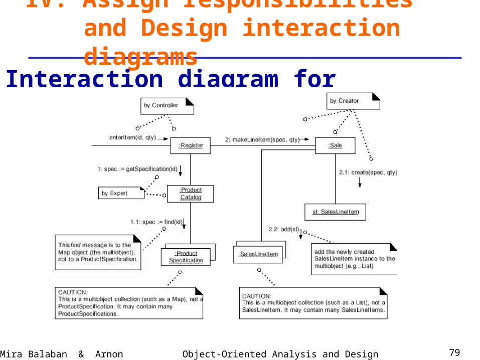
IV. Assign responsibilities and Design interaction diagrams
Summary of decisions:• Register sends a specification message to
ProductCatalog (visibility argument).• ProductCatalog sends a find message to the collection
(object) of ProductSpecifications that it contains.
Interaction diagram for enterItem:
Object-Oriented Analysis and DesignMira Balaban & Arnon Sturm 79
IV. Assign responsibilities and Design interaction diagrams
Interaction diagram for enterItem:

Object-Oriented Analysis and DesignMira Balaban & Arnon Sturm 80
Design interaction diagrams –System events:
1. makeNewSale.
2. enterItem.
3. endSale.
4. Sale – getTotal: Presentation requirement.
5. makePayment.
6. Payment – getBalance: Presentation requirement.
7. startUp.
IV. Assign responsibilities and Design interaction diagrams
Object-Oriented Analysis and DesignMira Balaban & Arnon Sturm 81
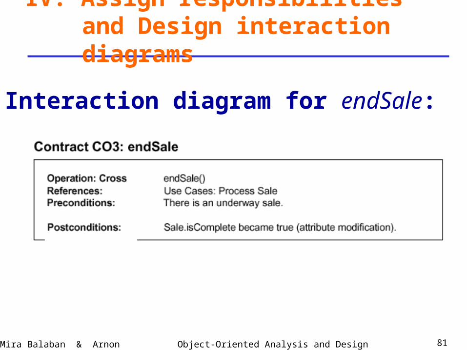
IV. Assign responsibilities and Design interaction diagrams
Interaction diagram for endSale:
Object-Oriented Analysis and DesignMira Balaban & Arnon Sturm 82
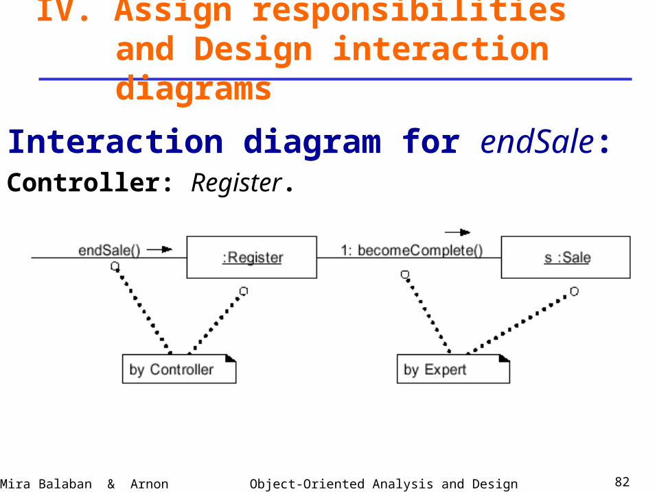
IV. Assign responsibilities and Design interaction diagrams
Interaction diagram for endSale:Controller: Register.
Object-Oriented Analysis and DesignMira Balaban & Arnon Sturm 83
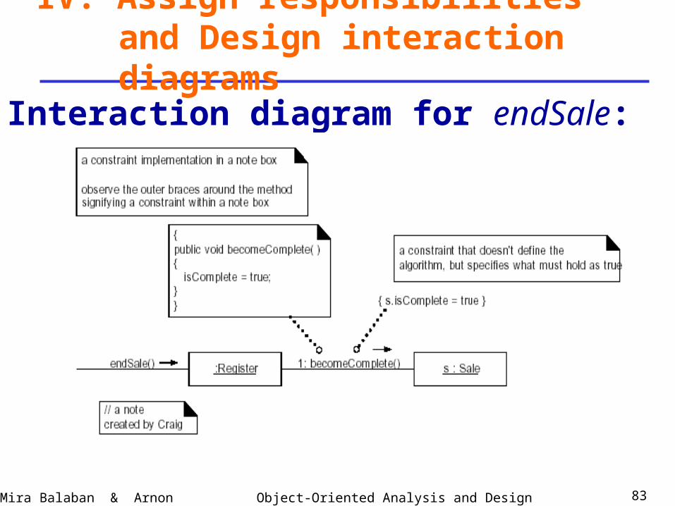
IV. Assign responsibilities and Design interaction diagrams
Interaction diagram for endSale:

Object-Oriented Analysis and DesignMira Balaban & Arnon Sturm 84
Design interaction diagrams –System events:
1. makeNewSale.
2. enterItem.
3. endSale.
4. Sale – getTotal: Presentation requirement.
5. makePayment.
6. Payment – getBalance: Presentation requirement.
7. startUp.
IV. Assign responsibilities and Design interaction diagrams
Object-Oriented Analysis and DesignMira Balaban & Arnon Sturm 85
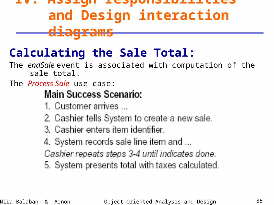
Calculating the Sale Total:The endSale event is associated with computation of the sale total.The Process Sale use case:
IV. Assign responsibilities and Design interaction diagrams
Object-Oriented Analysis and DesignMira Balaban & Arnon Sturm 86
IV. Assign responsibilities and Design interaction diagrams
Calculating the Sale Total:The presentation is not handled in designing the domain layer –Model-View separation principle.
But – the domain layer should provide the Sale-Total service.
Who will trigger this operation – probably the presentation layer.
getTotal can be viewed as a regular system operation (event).
Object-Oriented Analysis and DesignMira Balaban & Arnon Sturm 87
Calculating the Sale Total:• Responsibility: Sale – by Expert.
• Summary of needed information:
total of sale = sum of subtotals,
taken over all SalesLineItem objects
contained in Sale.
subtotal of a SalesLineItem = SalesLineItem.quantity *
ProductSpecification.price.
IV. Assign responsibilities and Design interaction diagrams
Object-Oriented Analysis and DesignMira Balaban & Arnon Sturm 88
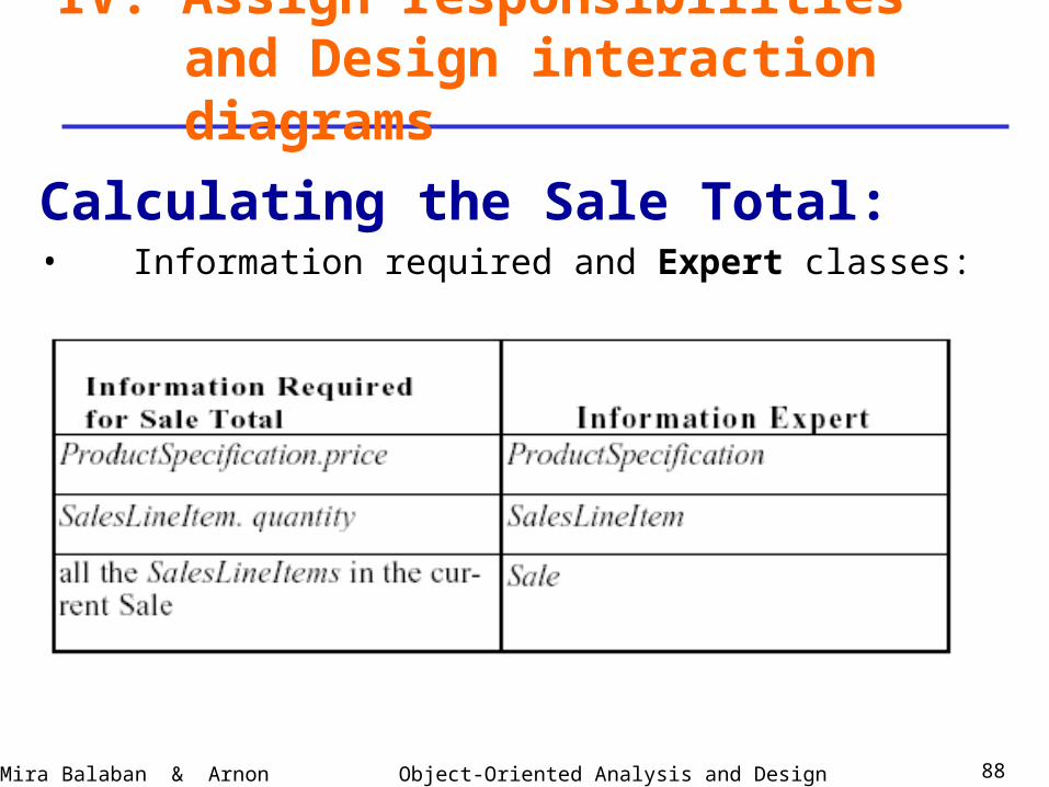
Calculating the Sale Total:• Information required and Expert classes:
IV. Assign responsibilities and Design interaction diagrams
Object-Oriented Analysis and DesignMira Balaban & Arnon Sturm 89
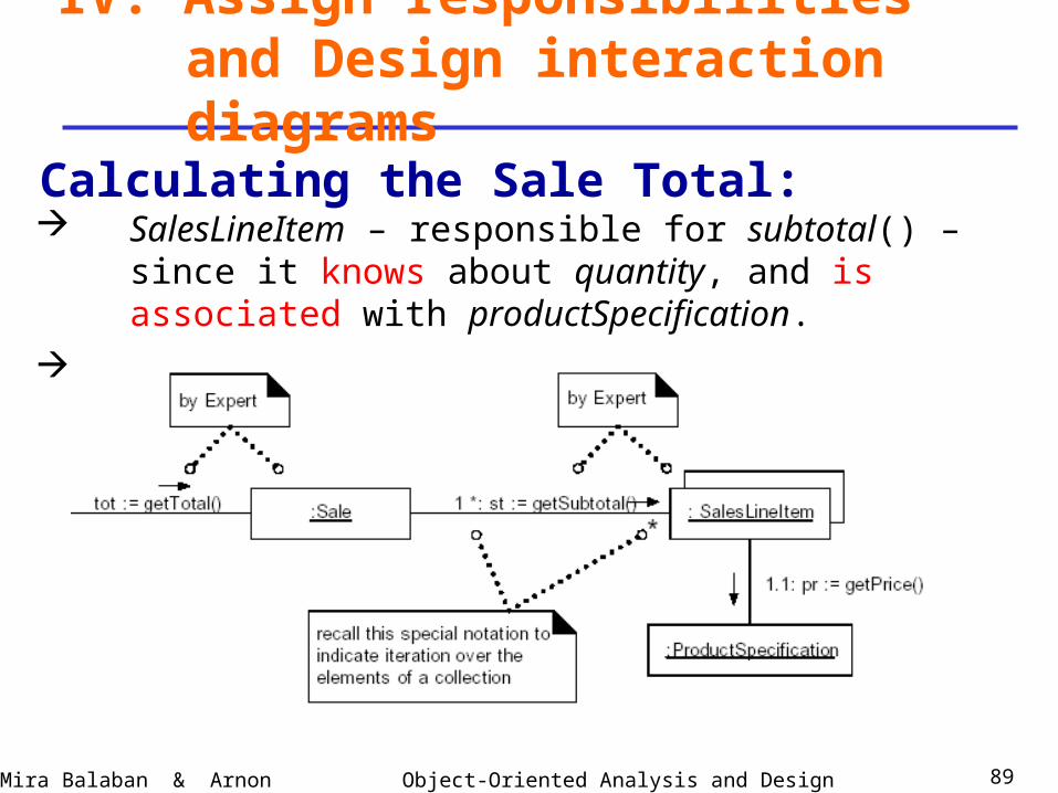
Calculating the Sale Total:
IV. Assign responsibilities and Design interaction diagrams
SalesLineItem – responsible for subtotal() – since it knows about quantity, and is associated with productSpecification.
Sale --- responsible for total ()

Object-Oriented Analysis and DesignMira Balaban & Arnon Sturm 90
Design interaction diagrams –System events:
1. makeNewSale.
2. enterItem.
3. endSale.
4. Sale – getTotal: Presentation requirement.
5. makePayment.
6. Payment – getBalance: Presentation requirement.
7. startUp.
IV. Assign responsibilities and Design interaction diagrams

Object-Oriented Analysis and DesignMira Balaban & Arnon Sturm 91
IV. Assign responsibilities and Design interaction diagrams
Object-Oriented Analysis and DesignMira Balaban & Arnon Sturm 92
IV. Assign responsibilities and Design interaction diagrams
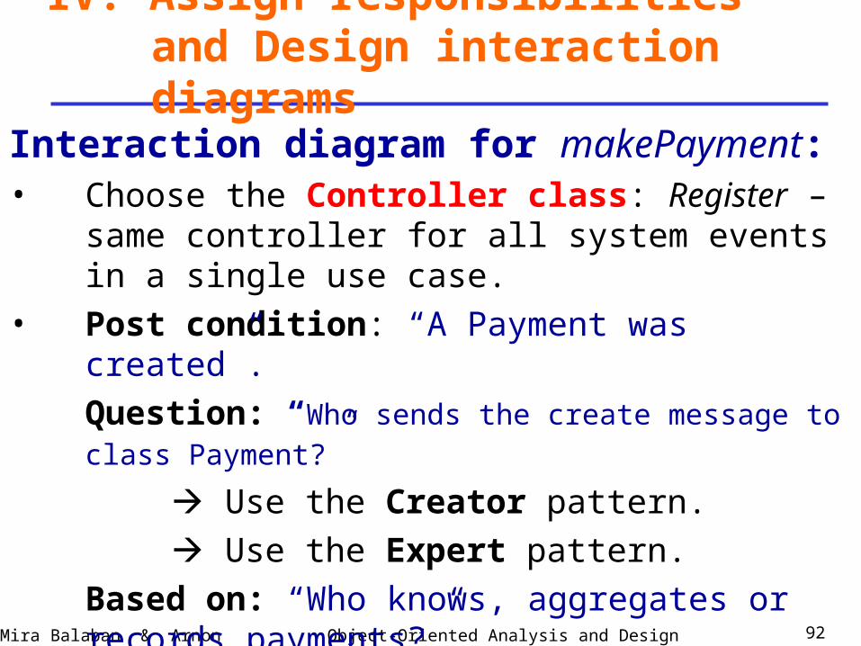
Interaction diagram for makePayment:• Choose the Controller class: Register – same controller
for all system events in a single use case.• Post condition: “A Payment was created”.
Question: “Who sends the create message to class Payment?”
Use the Creator pattern.
Use the Expert pattern.
Based on: “Who knows, aggregates or records payments?”
2 candidates: Register, Sale.
Object-Oriented Analysis and DesignMira Balaban & Arnon Sturm 93
IV. Assign responsibilities and Design interaction diagrams
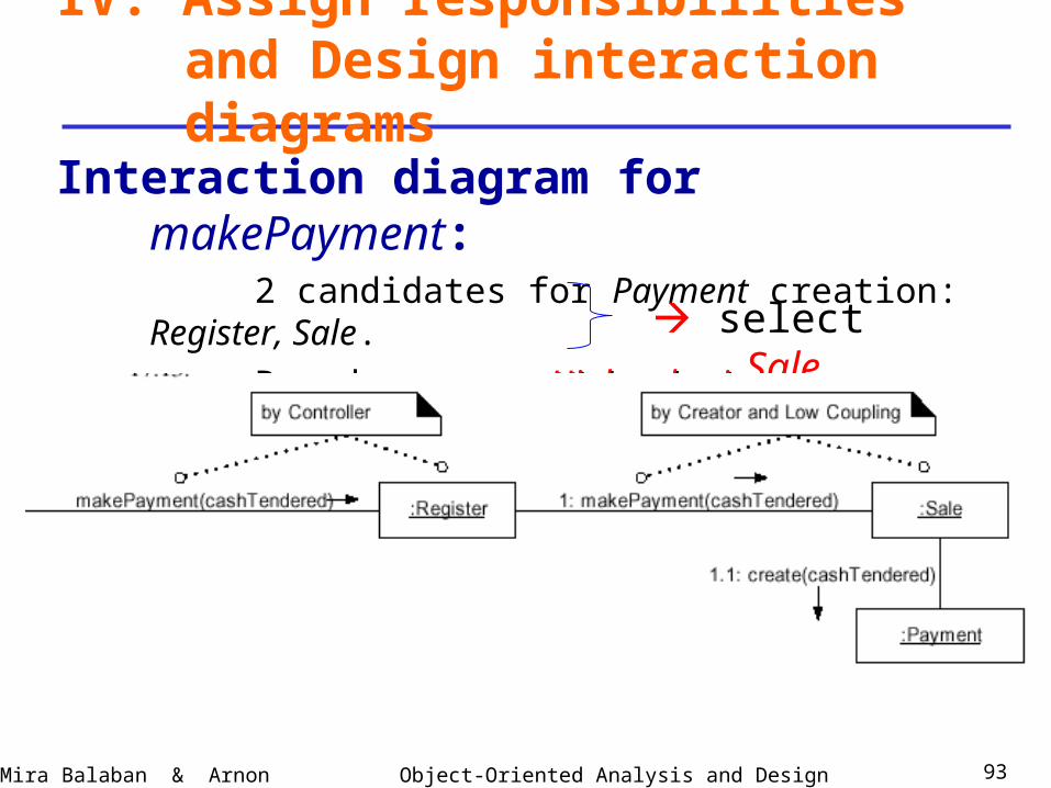
Interaction diagram for makePayment:2 candidates for Payment creation: Register, Sale.
Based on: High cohesion.High cohesion.
Low coupling.Low coupling. select Sale.
Object-Oriented Analysis and DesignMira Balaban & Arnon Sturm 94
IV. Assign responsibilities and Design interaction diagrams
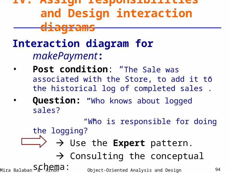
Interaction diagram for makePayment:• Post condition: “The Sale was associated with the Store,
to add it to the historical log of completed sales”.
• Question: “Who knows about logged sales?”
“Who is responsible for doing the logging?”
Use the Expert pattern.
Consulting the conceptual schema:
select Store.
Object-Oriented Analysis and DesignMira Balaban & Arnon Sturm 95
IV. Assign responsibilities and Design interaction diagrams
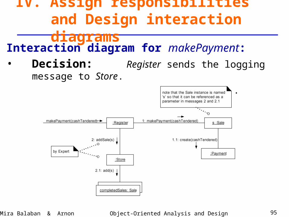
Interaction diagram for makePayment:• Decision: Register sends the logging message to Store.
Store does the logging.

Object-Oriented Analysis and DesignMira Balaban & Arnon Sturm 96
Design interaction diagrams –System events:
1. makeNewSale.
2. enterItem.
3. endSale.
4. Sale – getTotal: Presentation requirement.
5. makePayment.
6. Payment – getBalance: Presentation requirement.
7. startUp.
IV. Assign responsibilities and Design interaction diagrams
Object-Oriented Analysis and DesignMira Balaban & Arnon Sturm 97
Calculating the balance of the payment:By the Process SaleProcess Sale use case –
The makePayment event is associated with – Balance computation,– receipt printing,– balance display.
IV. Assign responsibilities and Design interaction diagrams
Object-Oriented Analysis and DesignMira Balaban & Arnon Sturm 98
IV. Assign responsibilities and Design interaction diagrams
Calculating the balance of the payment :The presentation is not handled in designing the domain layer –Model-View separation principle.
But – the domain layer should provide the getBalance service.
Who will trigger this operation – probably the presentation layer.
getBalance can be viewed as a regular system operation (event).
Object-Oriented Analysis and DesignMira Balaban & Arnon Sturm 99
IV. Assign responsibilities and Design interaction diagrams
Calculating the balance of the payment :• Question: “Who knows about balance?”
Needed information: – Sale total;
– Cash tendered.
By Expert:
Candidate classes: Sale,
Payment.
Object-Oriented Analysis and DesignMira Balaban & Arnon Sturm 100
IV. Assign responsibilities and Design interaction diagrams
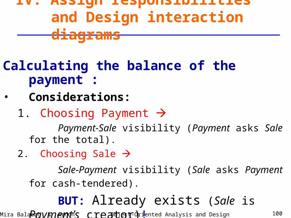
Calculating the balance of the payment :• Considerations:
1. Choosing Payment
Payment-Sale visibility (Payment asks Sale for the total).
2. Choosing Sale
Sale-Payment visibility (Sale asks Payment for cash-
tendered).
BUT: Already exists (Sale is Payment’s creator)!
Object-Oriented Analysis and DesignMira Balaban & Arnon Sturm 101
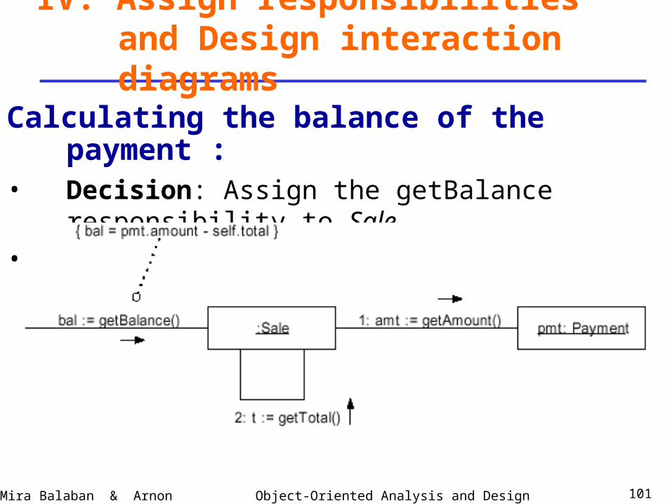
IV. Assign responsibilities and Design interaction diagrams
Calculating the balance of the payment :• Decision: Assign the getBalance responsibility to Sale.• Argumentation: Supports low-coupling.
Object-Oriented Analysis and DesignMira Balaban & Arnon Sturm 102
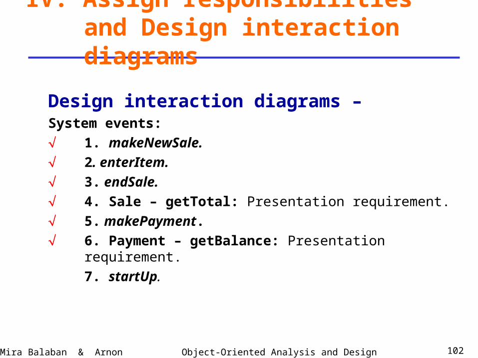
Design interaction diagrams –System events:
1. makeNewSale.
2. enterItem.
3. endSale.
4. Sale – getTotal: Presentation requirement.
5. makePayment.
6. Payment – getBalance: Presentation requirement.
7. startUp.
IV. Assign responsibilities and Design interaction diagrams
Object-Oriented Analysis and DesignMira Balaban & Arnon Sturm 103
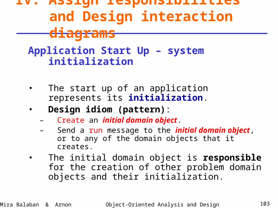
Application Start Up – system initialization
• The start up of an application represents its initialization.
• Design idiom (pattern):– Create an initial domain object.– Send a run message to the initial domain object, or
to any of the domain objects that it creates.
• The initial domain object is responsible for the creation of other problem domain objects and their initialization.
IV. Assign responsibilities and Design interaction diagrams
Object-Oriented Analysis and DesignMira Balaban & Arnon Sturm 104
Application Start Up – system initialization
• How to choose the initial domain object?– A class that represents the entire logical information
system.
– A class that represents the overall business or organization.
• Use the High Cohesion and Low Coupling criteria for choosing.
IV. Assign responsibilities and Design interaction diagrams
Object-Oriented Analysis and DesignMira Balaban & Arnon Sturm 105
Application Start Up – system initialization
• Who creates and runs the application?– Creation of the initial domain object – Message sent
by an object of the presentation (interface) layer.
– Running (controlling) the application – Either the initial domain object or the presentation layer.
IV. Assign responsibilities and Design interaction diagrams
Object-Oriented Analysis and DesignMira Balaban & Arnon Sturm 106
Application Start Up for the POS system:• Initial domain object: Choose between
– Register – entire logical information system.
– Store – overall business.
Decision based on high cohesion: Store.• Who creates and runs in POS:
– Creation -- A presentation object like a GUI object.
– Running -- A presentation object.
IV. Assign responsibilities and Design interaction diagrams
Object-Oriented Analysis and DesignMira Balaban & Arnon Sturm 107
Application Start Up for the POS system:• Persistent object decisions – database objects:
A persistent object persists throughout the life of the system.Stored persistently: files, databases.
• Decision on persistent objects – In POS: ProductSpecification.
• Decision on a mediating object – In POS: ProductCatalog.
IV. Assign responsibilities and Design interaction diagrams
Object-Oriented Analysis and DesignMira Balaban & Arnon Sturm 108
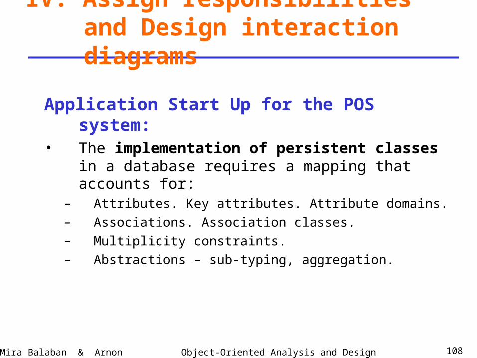
Application Start Up for the POS system:• The implementation of persistent classes in a
database requires a mapping that accounts for:– Attributes. Key attributes. Attribute domains.
– Associations. Association classes.
– Multiplicity constraints.
– Abstractions – sub-typing, aggregation.
IV. Assign responsibilities and Design interaction diagrams
Object-Oriented Analysis and DesignMira Balaban & Arnon Sturm 109
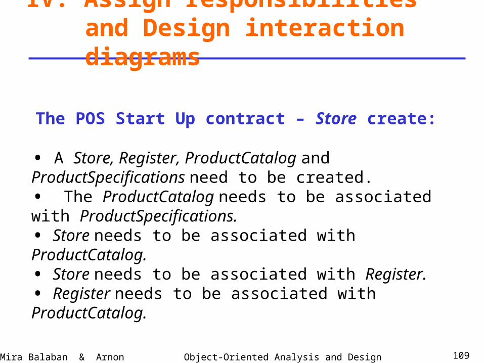
The POS Start Up contract – Store create:
IV. Assign responsibilities and Design interaction diagrams
• A Store, Register, ProductCatalog and ProductSpecifications need to be created.• The ProductCatalog needs to be associated with ProductSpecifications.• Store needs to be associated with ProductCatalog.• Store needs to be associated with Register.• Register needs to be associated with ProductCatalog.
Object-Oriented Analysis and DesignMira Balaban & Arnon Sturm 110
IV. Assign responsibilities and Design interaction diagrams
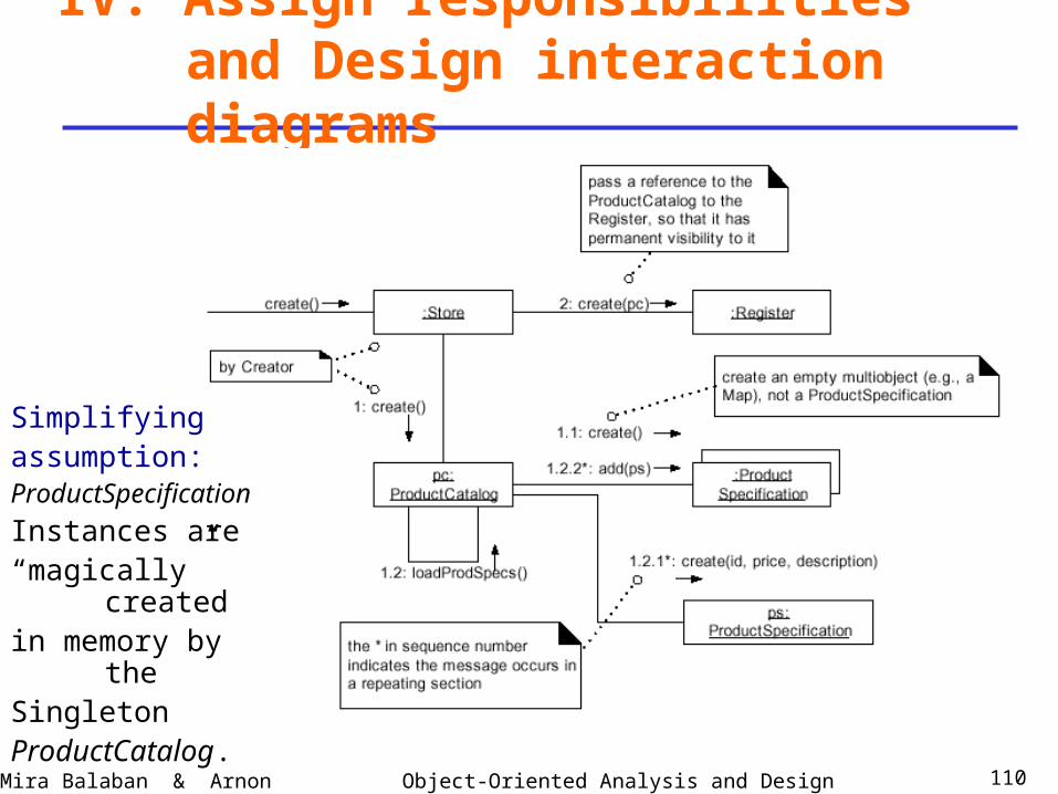
Simplifyingassumption:ProductSpecification
Instances are“magically” createdin memory by theSingleton ProductCatalog.
Object-Oriented Analysis and DesignMira Balaban & Arnon Sturm 111
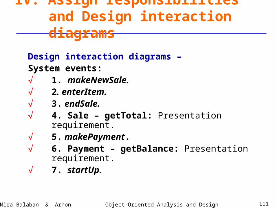
Design interaction diagrams –System events: 1. makeNewSale. 2. enterItem. 3. endSale. 4. Sale – getTotal: Presentation requirement. 5. makePayment. 6. Payment – getBalance: Presentation requirement. 7. startUp.
IV. Assign responsibilities and Design interaction diagrams
Object-Oriented Analysis and DesignMira Balaban & Arnon Sturm 112
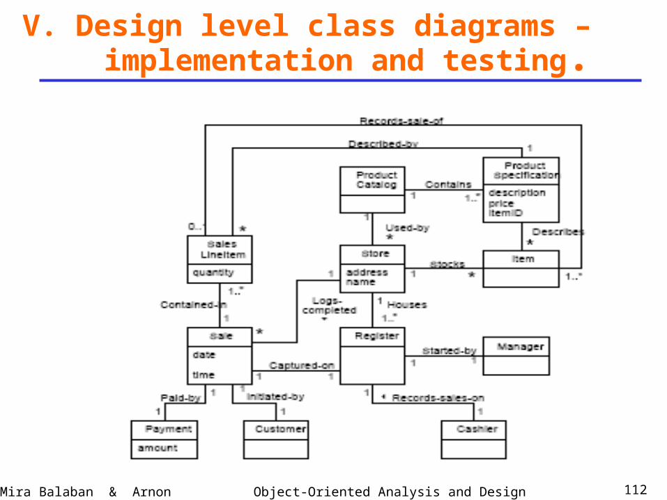
V. Design level class diagrams –
implementation and testing.
Object-Oriented Analysis and DesignMira Balaban & Arnon Sturm 113
V. Design Class Diagrams – Implementation
This stage is responsible for mapping designartifacts to code.Two steps:1. Develop Design Class Diagrams (DCDs).2. Implement.
Design class diagrams are developed in parallel to the development of interaction diagrams!
Object-Oriented Analysis and DesignMira Balaban & Arnon Sturm 114
V. Design Class Diagrams – Implementation
A Design Class Diagram (DCD) providesspecification for a software class or interface.It includes:• Classes, associations, typed attributes, data-types.• Interfaces – with operations.• Methods – with signatures.• Navigability – permanent (attribute) visibility.• Dependencies – temporary visibilities.
Object-Oriented Analysis and DesignMira Balaban & Arnon Sturm 115
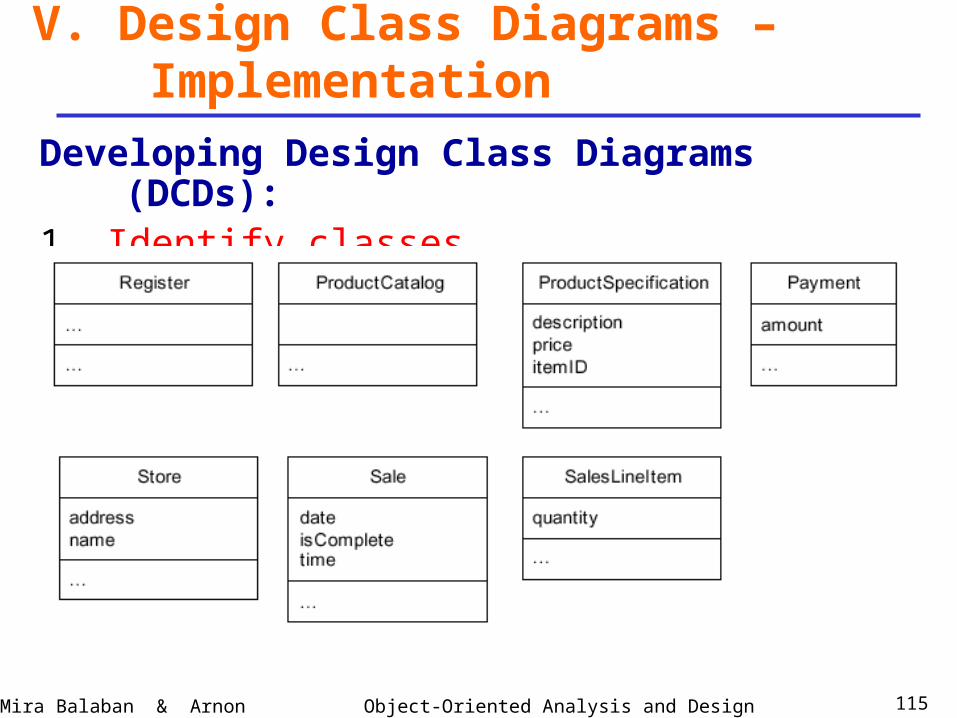
V. Design Class Diagrams – Implementation
Developing Design Class Diagrams (DCDs):1. Identify classes.
Object-Oriented Analysis and DesignMira Balaban & Arnon Sturm 116
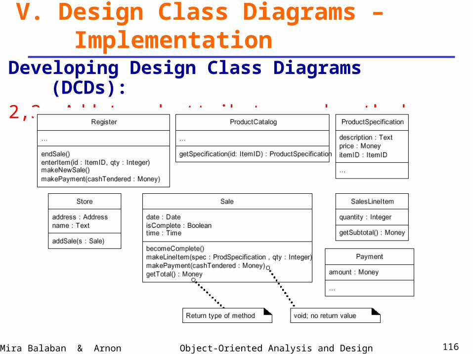
V. Design Class Diagrams – Implementation
Developing Design Class Diagrams (DCDs):2,3. Add typed attributes and methods with signatures.
Object-Oriented Analysis and DesignMira Balaban & Arnon Sturm 117
V. Design Class Diagrams – Implementation
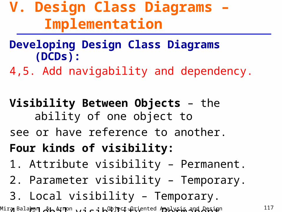
Developing Design Class Diagrams (DCDs):4,5. Add navigability and dependency.
Visibility Between Objects – the ability of one object to
see or have reference to another.
Four kinds of visibility:
1. Attribute visibility – Permanent.
2. Parameter visibility – Temporary.
3. Local visibility – Temporary.
4. Global visibility – Permanent.
Object-Oriented Analysis and DesignMira Balaban & Arnon Sturm 118
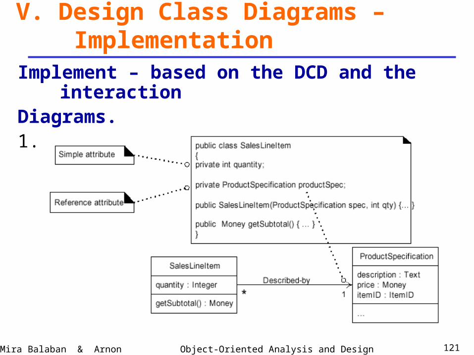
V. Design Class Diagrams – Implementation
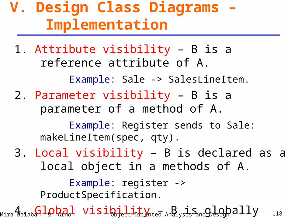
1. Attribute visibility – B is a reference attribute of A.
Example: Sale -> SalesLineItem.
2. Parameter visibility – B is a parameter of a method of A.
Example: Register sends to Sale: makeLineItem(spec, qty).
3. Local visibility – B is declared as a local object in a methods of A.
Example: register -> ProductSpecification.
4. Global visibility – B is globally visible.
Example: B has static methods.
Object-Oriented Analysis and DesignMira Balaban & Arnon Sturm 119
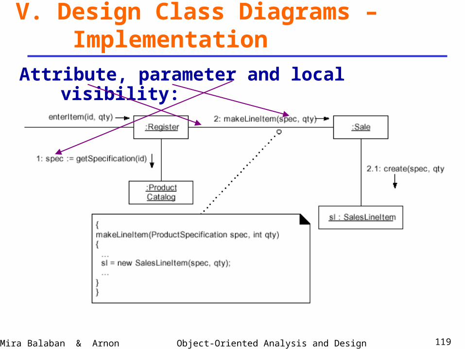
V. Design Class Diagrams – Implementation
Attribute, parameter and local visibility:
Object-Oriented Analysis and DesignMira Balaban & Arnon Sturm 120
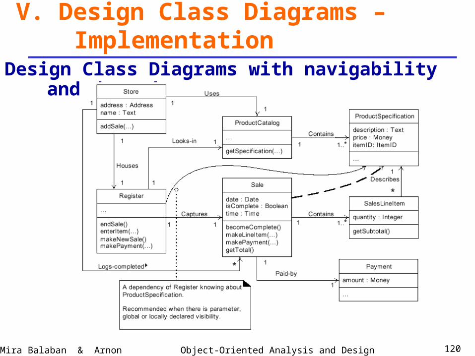
V. Design Class Diagrams – Implementation
Design Class Diagrams with navigability and dependency.
Object-Oriented Analysis and DesignMira Balaban & Arnon Sturm 121
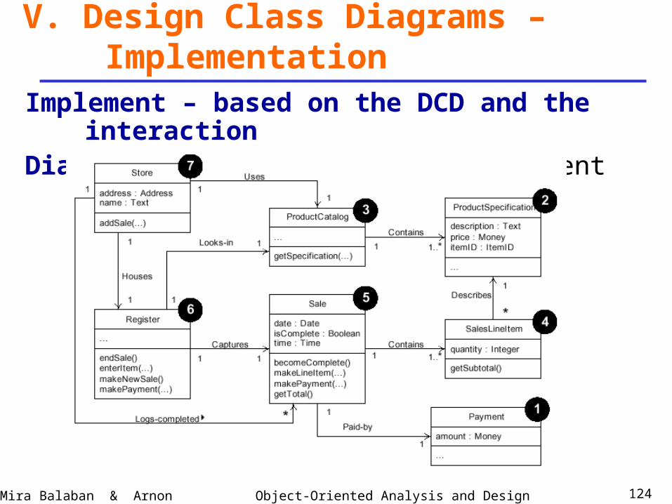
V. Design Class Diagrams – Implementation
Implement – based on the DCD and the interactionDiagrams.1. Adding reference attributes:
Object-Oriented Analysis and DesignMira Balaban & Arnon Sturm 122
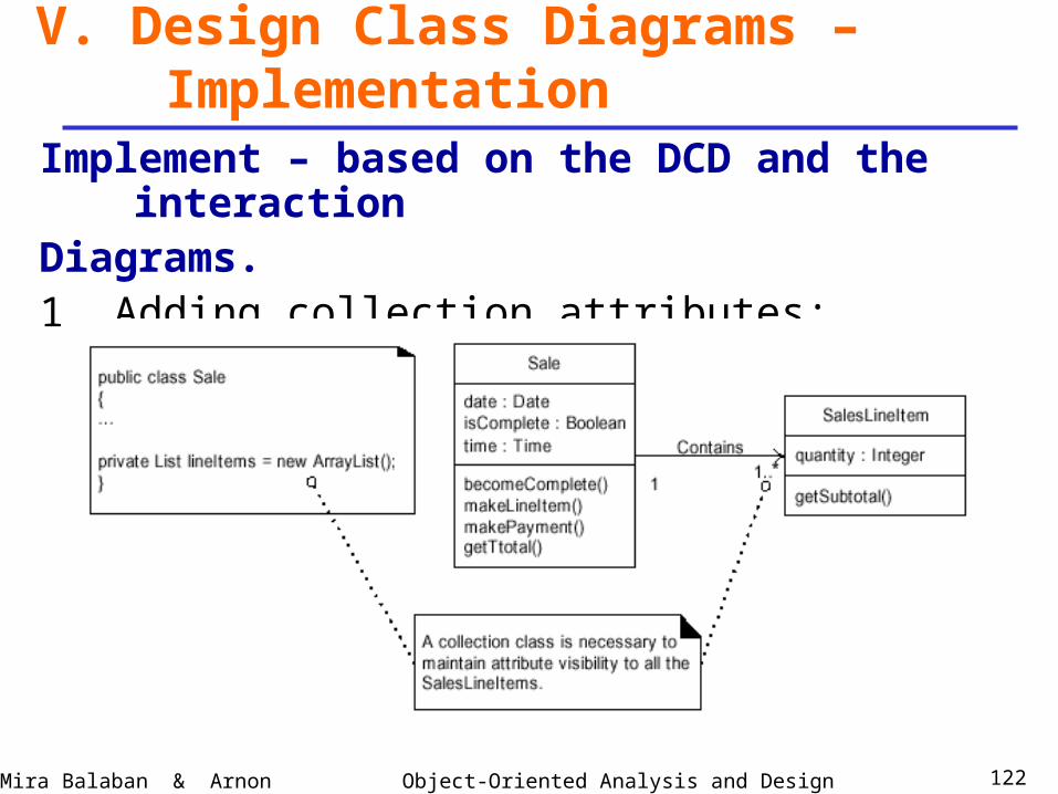
V. Design Class Diagrams – Implementation
Implement – based on the DCD and the interactionDiagrams.1. Adding collection attributes:
Object-Oriented Analysis and DesignMira Balaban & Arnon Sturm 123
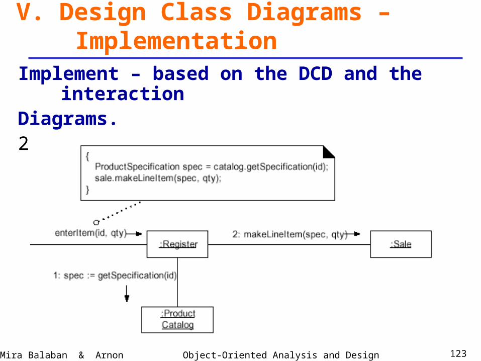
V. Design Class Diagrams – Implementation
Implement – based on the DCD and the interactionDiagrams.2. Adding methods:
Object-Oriented Analysis and DesignMira Balaban & Arnon Sturm 124
V. Design Class Diagrams – Implementation
Implement – based on the DCD and the interactionDiagrams. Possible test-and-implement ordering:
Object-Oriented Analysis and DesignMira Balaban & Arnon Sturm 125
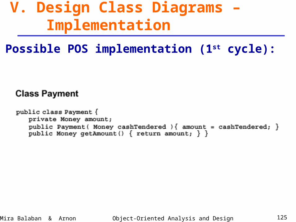
V. Design Class Diagrams – Implementation
Possible POS implementation (1st cycle):
Object-Oriented Analysis and DesignMira Balaban & Arnon Sturm 126
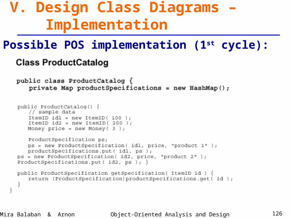
V. Design Class Diagrams – Implementation
Possible POS implementation (1st cycle):
Object-Oriented Analysis and DesignMira Balaban & Arnon Sturm 127
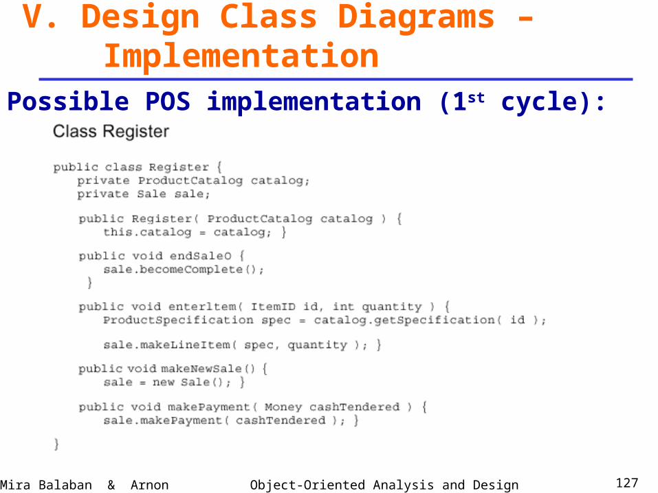
V. Design Class Diagrams – Implementation
Possible POS implementation (1st cycle):
Object-Oriented Analysis and DesignMira Balaban & Arnon Sturm 128
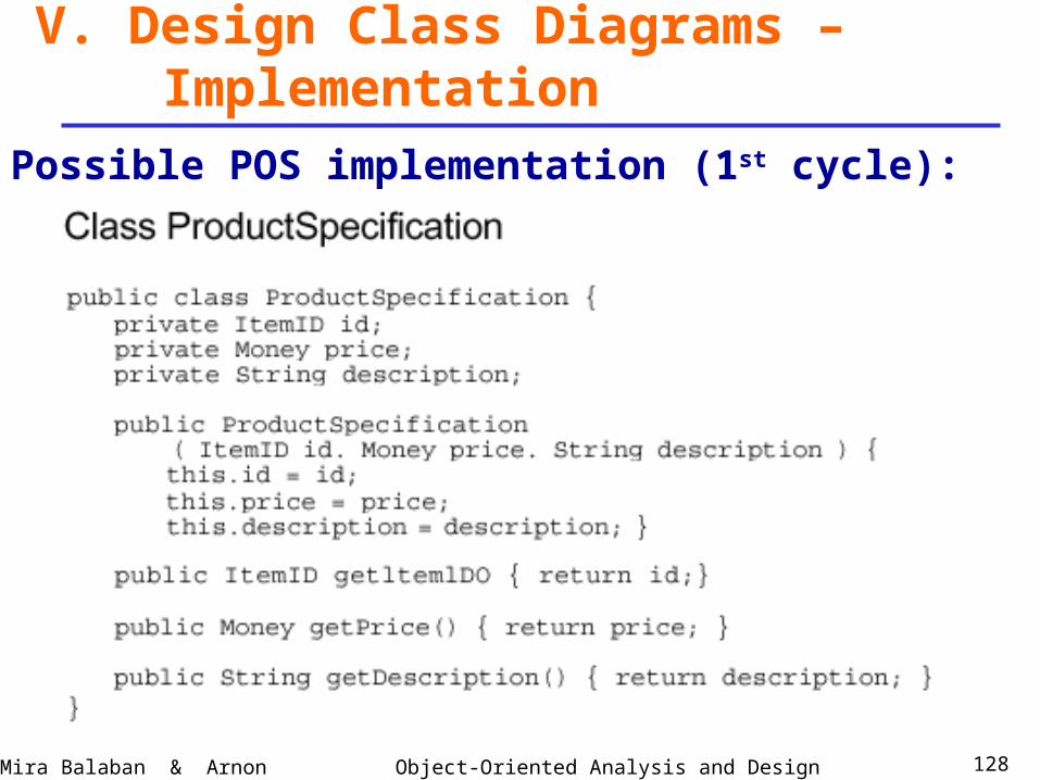
V. Design Class Diagrams – Implementation
Possible POS implementation (1st cycle):
Object-Oriented Analysis and DesignMira Balaban & Arnon Sturm 129
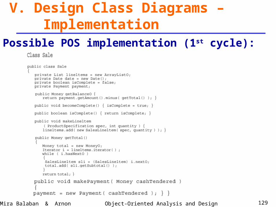
V. Design Class Diagrams – Implementation
Possible POS implementation (1st cycle):
Object-Oriented Analysis and DesignMira Balaban & Arnon Sturm 130
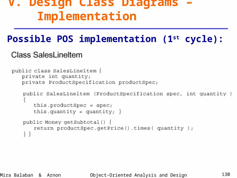
V. Design Class Diagrams – Implementation
Possible POS implementation (1st cycle):
Object-Oriented Analysis and DesignMira Balaban & Arnon Sturm 131
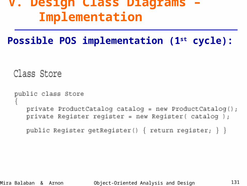
V. Design Class Diagrams – Implementation
Possible POS implementation (1st cycle):
Object-Oriented Analysis and DesignMira Balaban & Arnon Sturm 132
Persistency decisions
Persistency decisions involve objects that deservepersistent storage – e.g., files, databases.
In the POS problem – move ProductSpecification to thedatabase. The ProductCatalog serves as a communicationchannel to the persistent objects.
The object relational mapping poses many problems,due to the mismatch between the data-structures.
Object-Oriented Analysis and DesignMira Balaban & Arnon Sturm 133
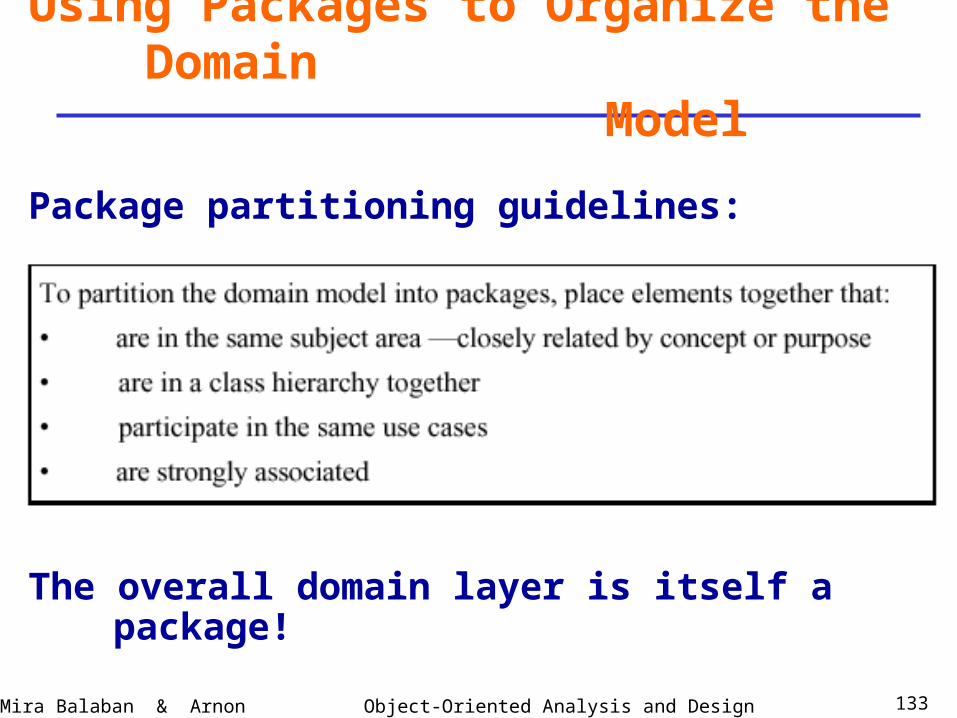
Using Packages to Organize the Domain Model
Package partitioning guidelines:
The overall domain layer is itself a package!
Object-Oriented Analysis and DesignMira Balaban & Arnon Sturm 134
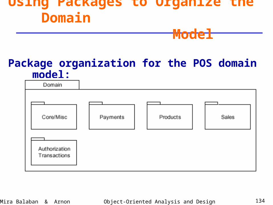
Using Packages to Organize the Domain Model
Package organization for the POS domain model:
Object-Oriented Analysis and DesignMira Balaban & Arnon Sturm 135
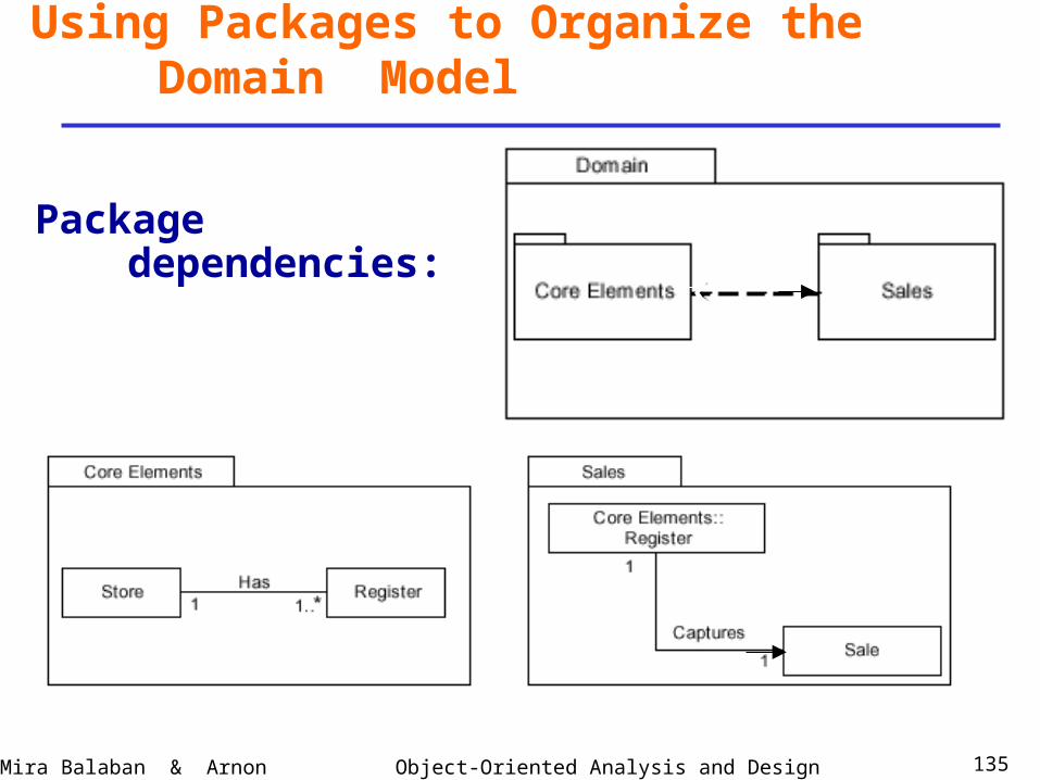
Using Packages to Organize the Domain Model
Package dependencies: