Object Interaction in Real-Time Virtual...
162
Object Interaction in Real-Time Virtual Environments THÈSE N° 2347 (2001) Présentée au Département d’Informatique École Polytechnique Fédérale de Lausanne Pour l’Obtention du grade de Docteur ès Sciences par Marcelo Kallmann Acceptée sur proposition du jury: Prof. R. Hersch, president Prof. D. Thalmann, directeur de thèse Prof. C. Petitpierre, rapporteur Prof. H. Bieri, rapporteur Prof. Y. Gardan, , rapporteur EPFL, 29 Janvier 2001
Transcript of Object Interaction in Real-Time Virtual...

Object Interaction in Real-Time Virtual Environments
THÈSE N° 2347 (2001)
Présentée au Département d’Informatique
École Polytechnique Fédérale de Lausanne
Pour l’Obtention du grade de Docteur ès Sciences
par
Marcelo Kallmann
Acceptée sur proposition du jury:
Prof. R. Hersch, president
Prof. D. Thalmann, directeur de thèse Prof. C. Petitpierre, rapporteur
Prof. H. Bieri, rapporteur Prof. Y. Gardan, , rapporteur
EPFL, 29 Janvier 2001

- ii -

- iii -
Abstract
This thesis is about the problem of how to achieve real time virtual environments with autonomous virtual human actors, which can interact with virtual objects in order to achieve a given task. The focus is on interaction with day life objects having some proper functionality and purpose, as for example: automatic doors, general furniture, or a lift.
The proposed approach is based on a complete definition and representation for interactive objects. A graphical modeler application was specifically developed in order to define such representation of interactive objects, which are called smart objects. This representation is based on the description of all interaction features: parts, movements, graspable sites, functionalities, etc. In particular, smart objects keep interaction plans for each possible actor-object interaction, detailing all primitive actions that need to be taken by both the object and the actor, in a synchronized way. Regarding the shape representation of objects, a new boundary representation data structure is introduced, providing low storage space requirements together with constant time access to adjacency relations; what is needed by many geometric algorithms.
An agent-based simulation environment is also presented with the built-in capability to simulate actor-object interactions, providing an automatic actor animation control for interactions with smart objects. The agent common environment (ACE) system is extendible and controllable with interactive Python scripts, and has been used as a system platform for research on behavioral animation. ACE incorporates many new solutions regarding the control of interactive virtual environments, including the interaction with smart objects using virtual reality devices.
The approach proposed in this thesis was tested in many different applications, and the results obtained are shown and discussed.

- iv -

- v -
Résumé
Cette thèse aborde le problème des environnements virtuels avec des acteurs virtuels autonomes qui peuvent interagir avec des objets virtuels pour accomplir une tâche donnée. On se concentre sur les interactions avec des objets courants qui ont une fonctionnalité et un but propres, par exemple: des portes automatiques, du mobilier, ou encore un ascenseur.
L’approche proposée est basée sur une définition et une représentation complètes des objets interactifs. Une application de type modeleur graphique a été développée pour permettre de représenter complètement les objets interactifs appelés objets intelligents (smart objects). Cette représentation est basée sur la description de toutes les caractéristiques d’interaction (interaction features): les parties, les mouvements possibles, les endroits pour saisir, les fonctionnalités, etc. Les objets intelligents contiennent en particulier des schémas d’interaction avec l’acteur. Ces schémas décrivent en détail toutes les actions élémentaires qui doivent être exécutées de façon synchronisée par l’acteur et par l’objet. En ce qui concerne la représentation géométrique des objets, nous introduisons une nouvelle structure de données utilisant peu d’espace mémoire tout en donnant des relations d’adjacence en temps constant. Ces caractéristiques sont très utiles pour des nombreux algorithmes géométriques.
Un environnement de simulation basé sur la conception agent a été aussi développé, avec la capacité de contrôler automatiquement l’animation des acteurs pour les faire interagir avec les objets intelligents. L’environnement commun des agents (ACE) est extensible et contrôlable depuis des scripts Python et est actuellement utilisé comme plate-forme de recherche et développement dans le domaine de l’animation comportementale. ACE propose plusieurs nouvelles solutions par rapport au contrôle des environnements interactifs, comme par exemple des interactions avec les objets intelligents en utilisant des dispositifs de réalité virtuelle.
L’approche proposée dans cette thèse a été testée avec de nombreuses applications et les résultats obtenus sont présentés et discutés.

- vi -

- vii -
Acknowledgments
It is an impossible task to not forget the many people who have contributed, directly or indirectly, to this work. As I could not simply omit such a page, I would like then to express all my thanks:
To Prof. Daniel Thalmann and all assistants of LIG for their invaluable support, in particular: Etienne de Sevin, Jean-Sebastien Monzani, Angela Caicedo, and Anthony Guye-Vuilleme, for all the help and motivation with Somod, ACE and Python; Paolo Baerlocher, Christophe Bordeux, Luc Emering, and Ronan Boulic for the many implementations and tunning of all the libraries; Selim Balcisoy, Soraia Musse, Nathalie Farenc, and Elsa Schweiss, for the many work done in collaboration; Tom Molet, Fabien Garat and Serge Rezzonico, for all the help concerning virtual reality devices; Olivier Renault, Mireille Clavien, Thierry Michellod, Olivier Paillet, Frederic Sidler, Rachel Cetre, Manuel Kurth, and Olivier Aune, for always helping with videos, models, etc; Amaury Aubel, Michal Ponder, Ralf Plaenkers, Christian Babski, Walter Maurel, Joaquim Esmerado, Luciana Nedel, Branislav Ulicny, Srikanth Bandi, Ik Soo Lim, Fabrice Vergnenegre, Nathalie Capdevielle, Richard Lengagne, and Nathalie Meystre for several different fruitful discussions; and also to Josiane Bottareli and Zerrin Celebi, for the help on many administrative issues.
To the EPFL students that I had the pleasure to work with in many different situations: Eric Devantay, Pedro Carnino, Pierre-Yves Burgy, Wendy Wanhonacker, Valery Tschopp, Marco Bonetti, Julien Beck, Luc Costabella, and Jurgen Anthamatten.
To the distant but very participative friends from COPPE/UFRJ: Ricardo Farias, Luiz Marcos Gonçalvez, Fernando Wagner, and Antonio Apolinário.
To the Brazilian National Council for Scientific and Technologic Development (CNPq), for the financial support.
To the many friends from the Club Alpin Suisse in Lausanne, and from the Carioca Mountaineering Club of Rio de Janeiro (CEC), for the many unforgettable climbings, and mainly, for not letting me forget that real life is much more important than virtual life.
To Suzane, Felipe and all my family, for the endless support during my life.

- viii -

- 1 -
1 Introduction............................................................................5
1.1 Motivation and Objectives .......................................................................... 6 1.2 Approach..................................................................................................... 6 1.3 Applications ................................................................................................ 8 1.4 Contribution ................................................................................................ 9 1.5 Organization of this Thesis ......................................................................... 9
2 Background, Terminology and Literature Review...............11
2.1 Modeling ................................................................................................... 11 2.1.1 Feature Modeling ............................................................................... 12 2.1.2 Scene Graphs and Skeletons .............................................................. 13 2.1.3 Actors and Objects ............................................................................. 14
2.2 Animation.................................................................................................. 14 2.2.1 Motion Generators.............................................................................. 15 2.2.2 Primitive Motions and Primitive Actions ........................................... 16 2.2.3 Behavioral Animation........................................................................ 17
2.3 Agents........................................................................................................ 18 2.3.1 The Virtual Environment ................................................................... 18 2.3.2 Autonomous Agents ........................................................................... 19 2.3.3 Programming Agents.......................................................................... 20
2.4 Virtual Reality........................................................................................... 23 2.4.1 Motion Trackers ................................................................................. 23 2.4.2 Force Feedback .................................................................................. 25 2.4.3 Stereographic Displays ....................................................................... 26 2.4.4 VRML ................................................................................................ 27 2.4.5 VR Systems ........................................................................................ 27
2.5 Used Software Libraries ............................................................................ 28 2.6 A More Precise Overview of This Thesis ................................................. 30 2.7 Chapter Conclusion................................................................................... 31
3 Star-Vertex Data Structure...................................................33
3.1 Introduction............................................................................................... 33 3.2 Related Work............................................................................................. 33 3.3 Star-Vertex Data Structure........................................................................ 35 3.4 Traverse Element ....................................................................................... 39 3.5 Analysis and Comparison.......................................................................... 43 3.6 Two Examples of Applications ................................................................. 44 3.7 Chapter Conclusion................................................................................... 45
4 Modeling Smart Objects .......................................................47
4.1 Introduction............................................................................................... 47

- 2 -
4.2 Related Work............................................................................................. 49 4.3 Feature Modeling of Interactive Objects................................................... 50
4.3.1 Interaction Features............................................................................ 51 4.3.2 Interpreting Interaction Features ........................................................ 53 4.3.3 Implementation Issues ........................................................................ 55
4.4 Somod Description.................................................................................... 55 4.4.1 Software Platform .............................................................................. 55 4.4.2 Defining Object Properties ................................................................. 56 4.4.3 Defining Interaction Information....................................................... 57 4.4.4 Defining Behaviors ............................................................................ 60 4.4.5 Templates ........................................................................................... 65
4.5 Somod Extensions ..................................................................................... 66 4.6 Chapter Conclusion................................................................................... 68
5 Interpreting Interaction Plans ..............................................69
5.1 Introduction............................................................................................... 69 5.2 Related Work............................................................................................. 70 5.3 Interpretation of Plans ............................................................................... 72
5.3.1 Instructions Reasoning ....................................................................... 73 5.4 Manipulation Actions ................................................................................ 74
5.4.1 The Inverse Kinematics Module ........................................................ 75 5.4.2 Constraints Distribution ..................................................................... 76 5.4.3 Animation Control.............................................................................. 77
5.5 Other Actions ............................................................................................ 79 5.6 Chapter Conclusion................................................................................... 80
6 Agent Common Environment ...............................................81
6.1 Introduction............................................................................................... 81 6.2 Related Work............................................................................................. 82 6.3 ACE System.............................................................................................. 82
6.3.1 Software Platform .............................................................................. 82 6.3.2 ACE Functionality.............................................................................. 83 6.3.3 A Script Example ............................................................................... 85
6.4 Multi Actor Simulations............................................................................ 87 6.5 User Control of the Animation.................................................................. 89 6.6 Extension Through Python Scripts............................................................ 91 6.7 Chapter Conclusion................................................................................... 93
7 Direct Interaction with Smart Objects..................................95
7.1 Introduction............................................................................................... 95 7.2 Related Work............................................................................................. 96

- 3 -
7.2.1 Interaction with Body Postures .......................................................... 96 7.2.2 Manipulation and Navigation............................................................. 96 7.2.3 Physical Models ................................................................................. 97 7.2.4 Manipulation Metaphors .................................................................... 97 7.2.5 High Level Metaphors........................................................................ 98
7.3 Smart Object Interaction Metaphor ........................................................... 99 7.3.1 Interaction Manager ........................................................................... 99 7.3.2 The Smart Object Controller............................................................ 101
7.4 An Interaction Example .......................................................................... 102 7.5 Analysis ................................................................................................... 103 7.6 Chapter Conclusion................................................................................. 104
8 Achievements and Results...................................................105
8.1 Modeled Smart Objects ........................................................................... 105 8.2 Urban Environment Simulations ............................................................. 107 8.3 Behavioral Animation............................................................................. 108 8.4 Virtual Life Simulations .......................................................................... 110 8.5 Direct Interaction..................................................................................... 112 8.6 Augmented Reality Applications ............................................................ 112
9 Conclusions.........................................................................115
9.1 Main Conclusions .................................................................................... 115 9.2 Limitations .............................................................................................. 116 9.3 Future work ............................................................................................. 117
10 Appendix..........................................................................119
10.1 Primitive Plans Instructions .................................................................... 119 10.2 Example of Smart Object Description Files............................................ 121
10.2.1 autodoor.so ....................................................................................... 121 10.2.2 desk.so .............................................................................................. 123 10.2.3 lift.so................................................................................................. 127
10.3 ACE Python Interface Description.......................................................... 131 10.4 ACE Example Python Scripts ................................................................. 134 10.5 Actor Skeleton Joints .............................................................................. 135
10.5.1 Skeleton Hierarchy........................................................................... 135 10.5.2 Joints Used by Action Push.............................................................. 137
References..................................................................................139
Curriculum Vitae ......................................................................153
Publications ..................................................................................................... 153

- 4 -

- 5 -
1 Introduction
Computer graphics systems are no longer synonym of a static scene showing 3D objects. In most nowadays applications, objects are animated, they have deformable shapes and realistic physically based movements. Such objects “exist” in virtual environments and are being used to simulate a number of different situations. For instance, costs are saved whenever it is possible to simulate and predict the result of a product before manufacture.
Technology has advanced, and now many standards exist in order to allow the creation and exchange of different kinds of data used in such environments. The increasing power of nowadays computers, associated with the lowering of costs, permits people to have all this technology available in their standard personal computers.
Users of such systems are no longer passive, but they can interact with virtual environments. Using special hardware devices, they can even realistically feel themselves immersed in these environments, interacting with virtual entities, feeling and seeing as if they were really inside this virtual reality.
Although many technical issues are not fully solved, a lot of attention has been given to a next step: lifelike behaviors. The issue is to have virtual entities existing in virtual environments, deciding their actions by their own, with realistic human appearance, animated with realistic movements, “living” in virtual environments and exhibiting proper and unpredictable behaviors. As a natural consequence, computer animation techniques today are strongly related to artificial intelligence and robotics techniques.
Researchers from areas like philosophy, psychology, cognitive sciences, etc, discuss whether virtual creatures can behave or not as living creatures. Fundamental concepts around human nature and artificial intelligence are still not fully understood. As particle physics share properties with astronomy, high-end technological issues are facing concepts of life.
The reader will not find any answers to such dilemmas in this thesis, neither the development of any new artificial intelligence technique. Instead, what I propose in this

- 6 -
work is a new alternate approach to exactly overcome the difficulty to model some specific intelligent behaviors in virtual actors.
This thesis focuses on the topic of object interaction inside virtual environments. Although many different related issues are also considered, I concentrate on the problem of how to have virtual environments with human-like characters and objects that can coherently interact between them, using the bottom-up approach for artificial intelligence, i.e., behavioral animation.
1.1 Motivation and Objectives
It is still a challenge to build in computers a virtual actor that can decide its motions, reacting and interacting with its virtual environment, in order to achieve a simple task given by the animator. This virtual actor might have its own way to decide how to achieve the given task, and so, many different sub-problems from many areas arise.
One of these sub-problems is how to give enough information to the virtual actor so that it is able to interact with each object of the scene. That means, how to give to an actor the ability of interaction with general objects, in a real-time application. This includes a lot of different kinds of interactions that can be considered. Some examples are: the action of pressing a button, opening a book, pushing a desk drawer, turning a key to then open a door and so on.
More than enabling actor-object interactions in virtual environments, another objective here is to address different solutions to let the animator control simulations, by giving tasks to actors or by interacting with objects. Note also that interactive virtual environments need, by nature, to run in real time. In this way, all issues addressed in this work take into account the need to run in real time systems.
A final challenging objective is to construct an interactive virtual environment to be used as a development platform for many applications, able to coordinate virtual actors and objects with proper behaviors, actor-object interactions, and user interaction with the environment.
1.2 Approach
In order to have virtual actors interacting with objects in the environment, there are many complex aspects to consider. Maybe the most difficult behavior to model is the actor capacity to recognize object features and to decide what actions are possible to perform with it. A human-like behavior would recognize a given object with vision and

- 7 -
touch, and then, based on past experiences and knowledge, the correct sequence of motions would be deduced and executed. Such approach is still too complex to be handled in a general case, and not suited for interactive systems where a real time execution is required.
To avoid complex and time-consuming algorithms that try to model the virtual actor’s “intelligence”, my proposed approach is to use a well defined object description where all properties, functionality features and a description of the steps to perform each available interaction are added to the geometrical shape description of the object. In that way, part of the most difficult thing to model, the knowledge of the virtual actor, is avoided. Instead, the designer of the object will use his own knowledge assigning to the object all information that the virtual actor need to access in order to interact with the object.
In order to create objects with such complete semantic and interaction description, a specific modeler was developed. This modeler can then define the behavioral interface between actors and objects based on interaction plans of primitive actions. Such interface is then used as an agent communication language to synchronize agent-object interactions. This modeler was implemented using some visual programming techniques, letting non-programmers to define object behaviors and actor-object interaction plans. Objects modeled with such behavioral information are called in this work as smart objects, and the smart object modeler application is called as somod.
This kind of approach has a parallel with the area of feature modeling, where specific object characteristics are included to allow design coherence, reusability, evolution and also automatic manufacture of the designed model. Here, the focus is on all the features that can help the virtual actor to interact with the object. For this purpose, I introduce the term interaction feature. Some examples of such features are: parts that can be moved, the definition of each movement, best hand positions and shapes to manipulate parts, etc.
This approach was tested using a developed agent-oriented system called ACE (Agent Common Environment), where virtual actors can read and interpret interaction plans to interact with virtual objects. This system presents interesting new characteristics, as the fact that the semantics of the environment stay distributed in the objects, so that virtual actors need to explore the environment to reach the objects and decide what interactions to perform to achieve a given task.

- 8 -
1.3 Applications
As a result of the growing popularity, and many technological advances, computers are each time more used for 3D animation and simulation in many different applications.
Computer animation in general has been widely used in the advertisement field, both in television and the internet. As technologies advance, many of these animations become three-dimensional, making them much more attractive. Electronic commerce already uses computer-generated promotion videos, and 3D models of products.
The film industry also uses many computer animation resources for the generation of special effects. However, for films, interactive virtual environments are not required, and normally the animation generation uses a lot of human intervention in order to achieve perfection in the results.
Visualization in general is each time closer to interactive graphics. From the visualization of 3D numerical datasets to the visualization of 3D architectural projects, vehicles, engineering components, etc. Walk-through in 3D environments can be enhanced with animated entities. For instance, a walk-through session for a 3D architectural evaluation can be much more realistic if virtual actors and objects are animated inside the virtual environment.
Interactive and animated 3D virtual environments are often used in modern video games in the market. The video game industry uses high-end techniques from computer graphics, and even starts to open new research directions in the field.
Virtual environments are already widely used for training and virtual prototyping. As it happened with the geometric modeling area, the automotive industry is investing a lot in virtual reality techniques for the design, test, and evaluation of human factors in vehicles. The same trend can be noticed in many other sectors, as the army and aerospace industries.
Virtual environments with virtual human actors simulations in specific, are becoming each time more popular. Nowadays many systems are available and used to animate virtual humans, targeting different domains, as: human factors analysis, training, education, virtual prototyping, simulation-based design, and entertainment.
In summary, nearly all applications using 3D animation in virtual environments are concerned with object interaction issues. Even if virtual human actors are less used because of the animation complexity involved, the possibility to have actor-object interactions in the virtual environment will always enhance the results obtained.

- 9 -
1.4 Contribution
The main contribution of this thesis is the design, implementation and test of a new approach to specify interactive objects, which are suitable for interactions between virtual human actors and virtual objects in real time virtual environments. In this ambit, new solutions to approach related topics are covered in this thesis, which are:
• A new data structure for the boundary representation of objects, which is able to give adjacency relations in constant time, requiring low storage space.
• A feature modeling approach to represent interaction information of objects. This approach is based on the definition of interaction plans, using visual programming techniques. Such plans define the behavioral interface of objects and their functionality, enabling simulators to load and animate them coherently.
• A simple and general methodology to control the animation of virtual human actors for performing object interaction manipulations. The simplicity comes from the fact that all hand manipulations are done with only two kinds of movements, which are: to reach some object part, and to follow some moving object part. Such simple movements can then be composed to create more complex and general interactions.
• A real time system which can be used for the development of interactive virtual environments for different applications, offering built-in capabilities for actor-object interactions, and for user simulation control, including a direct object interaction metaphor using virtual reality devices.
1.5 Organization of this Thesis
In this introductory chapter, I have already freely used many terms without a proper definition of their meanings, which are normally context dependent. The next chapter will gradually introduce the needed background and define each used term, creating a coherent terminology to be used along the remaining chapters. Some general related works are also mentioned, but specific references to each subtopic are given in their specific chapters.
Chapter 3 introduces a proposed new data structure for the boundary representation of objects, and chapter 4 exposes how interactive objects can be modeled and represented with their interaction features and interaction plans. Chapter 5 explains how virtual actors interpret interaction plans, and the animation techniques involved for the animation control of actors during object interaction.
Chapter 6 introduces a system that is able to control actor-object interactions, according to the modeled interaction plans. This system is agent oriented and offers many

- 10 -
tools for the simulation control, including an interaction metaphor to let users interact with objects using virtual reality devices, which is the specific topic of chapter 7.
Chapter 8 presents the many results obtained with the proposed techniques, and finally chapter 9 concludes this thesis. In addition, an appendix section is included, containing information about implementation issues, scripts and used data files.

- 11 -
2 Background, Terminology and Literature Review
This chapter makes an overview of the terminology, concepts and background notions that are used along this thesis. They are grouped among the many areas touched by this work, and are introduced slowly, starting with computer graphics related areas, and ending up with concepts from artificial intelligence domains. However, it is assumed that this is not the first contact that the reader has with the covered topics, so that terms and concepts are not exhaustively discussed.
Along the text, this chapter also presents a general literature review of related areas. However, an in-depth discussion of the related works, regarding each sub-topic of this thesis, is presented in each specific chapter.
At the end, already using a more precise terminology, a description of the software modules and libraries used in this work is done, and a more precise description of the work proposed in this thesis is presented.
2.1 Modeling
The term modeling is used by nearly all sciences, for many different purposes. In general, a model is an artificially constructed object that makes the observation of another object easier. The term solid modeling is extensively used in computer graphics, mainly in the areas of computer aided design (CAD) and computer aided manufacture (CAM). The solid modeling area gives computational representations for objects that have a possible physical realization. Along this thesis, I will rather use the term object modeling, to refer to computational representations of objects that can be coherently displayed by the computer, even if a physical realization is not straightforward. For example, a mathematical plane in the 3D space does not exist in our real world, as its thickness would need to have a measurable dimension; but it can be coherently displayed by computers.

- 12 -
There are several proposed computational representations for objects, each one having its advantages and drawbacks. Some popular examples are: volumetric representations, constructive solid geometry (CSG) trees, and boundary representations. For a detailed description of such representations, I refer the user to the classical book of [Mäntylä 1988].
The Boundary representation (BRep) is one popular way to represent objects. BRep schemes represent objects by describing their surface boundary, which can be composed of planar faces and curved surfaces. Geometric modeling is the area where mathematical representations of curves and surfaces to represent solids are studied. With such mathematical representations, it is possible to accurately describe curved surfaces. One example of a popular surface representation is the nonuniform rational B-spline (NURBS). Among others, a classical reference to this topic is [Farin 1992].
Objects in BRep are easy to display in computers, i.e., to render. This is based to the fact that surfaces can be always approximated, given any desired precision, by a set of planar 3D polygons. Most nowadays computers provide specific hardware to render 3D polygons efficiently. The speed factor achieved with the use of such hardware (or graphics cards) has largely contributed with the popularity of BRep models. As speed is crucial in interactive applications, only BRep of objects are used in this work, and a new BRep data structure to represent objects is proposed in the next chapter.
2.1.1 Feature Modeling
Object modeling deals with the shape representation of an object. However, in many applications, other properties different than shape need also to be represented. Feature modeling is a technique used mostly by CAD/CAM applications [Shah 1995] where the main concern is to represent not only the shape of the object, but also all other important features, in the context of the application.
One concrete example in a CAD application is the design of a simple pen’s cap that has a small hole in its original design. Suppose now that a new designer working on this model would prefer to close that small hole just because of esthetic reasons. Then, during the operation, he or she would see a note from the original designer saying that the hole was done in order to prevent children to stop breathing if they accidentally choke with the pen’s cap. Such information is very important in this situation and so it is included in the object’s representation.
Following these concepts, I have coined the term interaction feature to refer to all interesting features of an object regarding its interaction capabilities. Some examples of interaction features are the modeling of the objects movements and its global

- 13 -
functionality. Feature modeling and interaction features are a key issue in this thesis and will be extensively discussed in the next chapters.
2.1.2 Scene Graphs and Skeletons
Sometimes objects can be composed of many parts, like disconnected components (or topologically: shells [Mäntylä 1988]). Parts may also have animation constraints, for example to specify that a part is only allowed to rotate around a specified rotation axis. When such composed objects are loaded, the connectivity of their parts is often represented with a scene graph.
Most commercial toolkits for the implementation of 3D computer graphics systems are based on scene graphs; examples are: Open Inventor, Performer, Optimizer, Fahrenheit, etc. More information about these toolkits can be obtained from the web pages of [SGI], [TGS], and [Microsoft]. Scene graphs permit to organize, animate and control a hierarchy of object parts. See for instance [Wernecke 1994], and the chapter 4 of [Thalmann 1991], for some examples of scene graphs implementations.
Figure 2.1 – A scene being displayed is commonly represented with a scene graph. The scene graph contains all necessary information to display each object of the scene. The internal hierarchy of each object’s parts is also represented as a graph that is the object skeleton, and can be seen as a branch in the main scene graph.
The word skeleton is also commonly used to refer to the specific scene graph of some given object in the scene. A skeleton defines all the connections of all parts of a given object, and also eventual transformations that can be applied to any node of the graph. These transformation nodes are also referred to as joints. Joints can be of different types and they will dictate the number of degrees of freedom (DOFs) in the skeleton. See the chapter 4 of [Thalmann 1991] for more explanation on these terms. Typically, a scene being displayed by the computer is represented by a single global scene graph, where the objects’ skeletons are specific branches of the scene graph (figure 2.1).
Scene Graph
Skeleton of an object

- 14 -
2.1.3 Actors and Objects
Objects can be built having a human-like appearance. Human-like objects can then be animated as characters in a scene, and are often referred to as virtual humans, or, for the sake of simplicity, actors. Some times the adjectives real and virtual will be used in order to distinguish a real (physical) object from its counterpart virtual object representation. The same adjectives can also be used to distinguish a real person from a virtual actor in some situations. Note that virtual actors share many properties with virtual objects. Both need to be modeled, to have a skeleton, and then to be animated. However, virtual humans are, in general, much more complex than objects.
From now on, when not contrary stated, the word object (or virtual object) will be used to refer to the computer representation of day life objects, like computers, tables, cupboards, doors, etc. The concept of what is an object is rather intuitive, and depends on the context. For instance, in many situations, it may not be clear if a robot model should be considered as an object or an actor.
In addition, composed objects are not trivial to be identified. For example, one can consider a furniture with many drawers as a single object composed of many parts, so that a skeleton scheme can be used with joints to define the possible movements of the drawers. All this information should be included in the feature modeling of the furniture. However, one can state that the furniture is an independent object, and the same for each drawer. In this example, it seems to be clear the correct design decision to take, but in many other cases, this decision is not straightforward: should a car, with all its doors, engine, wheels, radio, etc, form a single object? An answer to this question is deeply context-dependent. In fact, even in real life situations we change the way we classify single and composed objects from time to time.
2.2 Animation
Once objects and actors models are created, they can be displayed in a computer screen. Computer animation introduces the dimension of time and allows the manipulation of these entities to create the illusion of animated movements.
Many different techniques are used in animation: key-framing animation, procedural animation, dynamic simulations, etc. Deformation techniques are also used to produce animation. For a good overview of the many techniques used in computer animation, see [Vince 1992], [Watt 1989], [Watt 1992], [Thalmann 1990] and [Thalmann 1993].

- 15 -
2.2.1 Motion Generators
Animation is direct related to the generation of motion. Movements that are applied to objects can be realistic generated using dynamics or inverse kinematics [Watt 1992]. But for virtual humans, the implementation of realistic motion generators is something more complex.
A motion generator will typically generate, for each time step of the simulation, new values for the joints of an actor’s skeleton. Note that a virtual human skeleton can be very complex, with more than a hundred of DOFs, resulting in a complex structure to animate. Also, realistic rendering of the actor involves the modeling of an initial shape, with consecutive deformation according to the movements of the underlying skeleton. Even simpler solutions based on rigid parts require a reasonable effort to model each independent body limb and to connect them coherently. For an exposition on some of the issues involved in this area, see, for instance [Badler 1999a], [Kalra 1998] and [Thalmann 1991]. Figure 2.2 shows some possible representations for virtual actors.
Figure 2.2 – Possible representations for an actor. From left to right: skeleton representation, body composed of rigid parts, and two models with deformable skin.
One popular animation technique for virtual humans is based on motion capture. The idea is to capture the movement of real persons by using some special hardware, based on high-end vision systems, magnetic sensors or infrared sensors. A brief introduction to this and other virtual reality devices will be given later in this chapter. With such kind of hardware, movements are captured by recording the position and orientation in space of each body limb of the person using sensors, at each time step. Once these movements are recorded, they can be mapped to the actor’s skeleton in order to produce a realistic animation, very close to the original movement. This mapping is not straightforward and different techniques exist, as for instance [Molet 1996].

- 16 -
The same kind of recorded movement can be synthesized with advanced animation software, and this general approach of using pre-defined movements (motion captured or manually created with a software) is called as keyframe animation.
However, serious problems arise when one needs to adapt a pre-recorded movement to skeletons of different sizes, or to dynamic situations. For example, it is very difficult to use a pre-defined movement to realistically animate the actor’s arm to pick-up an object that can be put at any position close to the actor. It is not reasonable to record an arm movement for all positions to reach in a discrete 3D space surrounding the actor; thus, other solutions are required.
Inverse kinematics is a technique that can calculate one optimal configuration of a skeleton from a number of given constraints. For an introductory text, see [Watt 1992], and as an example of some latest advances achieved with inverse kinematics techniques, see [Baerlocher 1998]. A typical example is to calculate the joint values of all joints of the actor’s arm, given a goal position and orientation to be reached by the hand. The drawback is that most inverse kinematics methods are based on minimization techniques, and thus undesirable local minima can occur. Additionally, the animation result is not always considered natural. A promising approach is to use combined solutions in order to obtain parameterized motion captured data; one step in this direction can be seen in [Bindiganavale 1998]. Although such efforts are promising, inverse kinematics is still the simplest solution adopted to overcome the adaptability difficulties of keyframe-based techniques.
An actor’s important motion that receives a lot of attention is walking. The movement of walking is difficult to realistically reproduce. It is difficult to achieve dynamics algorithms taking into account all needed subtleties of natural movement. In another sense, motion capture techniques are hard to be efficiently parameterized to work on all kind of skeletons, and to work with different speeds and ways of walking. A hybrid approach is somehow required. As an example of proposed walk motors, see, for instance, [Tsutsuguchi 2000] and [Boulic 1990].
2.2.2 Primitive Motions and Primitive Actions
All these motion generators may be used together to generate a wide range of animations. Motions obtained with these techniques are going to be called primitive motions. Primitive motions can be used for different purposes. For example, inverse kinematics can be used to make the arm of the actor reach the position of a button, before pressing it. This action of reaching will be considered to be a primitive action, as it is directly generated by a primitive motion. Similarly, primitive actions applied to objects will move its parts, as to open and close drawers of some furniture.

- 17 -
Suppose now that an animation system provides the possibility to apply many different kinds of primitive actions to actors and objects. A first concern is the problem of coherently mixing the output of motion generators when they are triggered in parallel. Although this is not a common case in objects, for the animation of actors this is an important issue also known as motion blending [Boulic 1997]. For example, a motion blending is required in order to have an actor that walks while its arm, for some other purpose, is controlled by an inverse kinematics motion generator with higher priority.
Once these capabilities of motion generation and blending over actors and objects are possible, the problem that arises is how to define the good combination of motions in order to simulate or animate a higher level task. More than that, when one wants to animate a complex scenario, it would be desirable to be able to do it in an efficient way. For instance, which parameters one would need to specify in order to animate a simple storyboard, as an actor that enters into a laboratory and takes a diskette of a computer? A first problem is the excessive amount of parameters to define. And once the work is done, as the animation was “pre-calculated”, it would not be interactive.
2.2.3 Behavioral Animation
When a virtual actor can just receive key instructions, or high level tasks, to perform some animation, a behavioral module is needed to deduce the correct primitive actions to apply, in order to achieve the given tasks. Many techniques exist to define behavioral modules, and such topic has a lot of attention in the behavioral animation and agents area.
Prior to the science of behavioral animation, researchers initially developed physics-based models to make movements more realistic. A main drawback was that the animation was always predictable, and did not take into account individualities of the characters. The first behavioral system was developed by [Reynolds 1987] and introduced the concept of flocking behavior to animate flocks of birds. In this system, an individual bird follows a set of rules that makes it to follow the surrounding birds, while avoiding colliding with them. With such individual rules, the flock of birds presents realistic results of group motion, which would be a time-consuming task to perform with traditional animation techniques. In a recent work, [Reynolds 1999] addresses many other types of locomotion behaviors.
Behavioral animation [Millar 1999] [Ziemke 1998] is considered to be the bottom-up approach to study artificial intelligence (AI). Traditionally, AI has been based on the view that intelligent behavior is the result of abstract processes at the “knowledge level” [Newel 1982]. But since the mid-1980s, traditional AI (which can be considered to be the “correct approach”) has shown serious problems in dealing with complex

- 18 -
environments. An alternate approach then appeared, based on behavioral-based robotics, focusing on perception and action [Brooks 1986].
Different perception techniques have been proposed and they will direct reflect the way that behavioral modules are designed. The first approach introduced to simulate realistic virtual human perception was done by [Renault 1990] which simulated a vision-based perception. [Tu 1994] has applied a spherical visual perception to simulate fishes and [Reynolds 1987] has applied to birds. [Noser 1996] has also used vision perception, together with memory, and the perception of sound events. To overcome the difficult task of dealing with a vision-based perception, [Bordeux 1999] proposed pipelines of perception, which are configurable with different properties in an efficient way.
2.3 Agents
Behavior-based AI has then used the term agent to refer to an entity based on perception and action. Unfortunately, this concept is applied in many different fields so that the term agent is used for all sorts of systems, ranging from the most complex (humans, animals) to the very simple (programs, subroutines) [Woolridge 1995] [Franklin 1996].
A common point is that an agent is always situated in an environment, and can interact with its environment by means of perception and action. Figure 2.3 depicts these main components of an autonomous agent.
Figure 2.3 – Agents are based on three main modules: perception, behavior, and action. To act ant perceive, they need to “exist” in a virtual environment.
2.3.1 The Virtual Environment
Agents need to have an associated virtual environment (VE) where they can perceive the state of the simulation in order to decide the motions to apply. The motions
Autonomous Agent
Virtual Environment
Behavioral Module A
ct
Perc
eive

- 19 -
are then visualized in the same VE, which keeps and manages the graphical representation of each agent. The concept of perception is directly related with the existence of a coherent VE, that needs to be able to efficiently answer perception queries.
Agents’ behavioral modules often run in an asynchronous way, using different computer processes, or threads (“light processes”). This is required so that, ideally, the process time consumed by one agent would not interfere with other agents. Thus agents would be able to access in parallel the needed information in the VE, exchange messages, etc.
The VE needs to display the graphical representation of each agent being animated, and efficiently answer to perception queries. The display need to be updated with a sufficient and constant refresh rate to show a smooth and time-coherent animation. This also involves the use of parallel processes to keep a constant frame-rate. In general, psychologists show that a frame rate of 25Hz is sufficient for the human eye to perceive motion flowing smoothly. When a frame rate close to 25Hz is achieved it is common to say that the system runs in real time. Note that an interactive system, by nature, requires real time performance. However, many times it is not possible to keep a real time frame rate, and even with lower frame rates, depending on the application, it is common to say that a system still runs with interactive frame rates.
2.3.2 Autonomous Agents
Many terms can then be used to better specify the agent type. An agent is considered to be autonomous, when it is able to achieve given goals by only its own actions in a continuous interaction with the VE. It can be considered intelligent if it can solve complex goals, otherwise it is just considered reactive. Normally, intelligent behaviors are able to generate emergent behaviors, which are behaviors that were not directly programmed, and appear as a result of other simpler behaviors. [Ziemke 1998]. Agents that “take the initiative” while attempting to achieve a goal are called as pro-active. They can have sociability characteristics to be able to cooperate and interact with other agents in the environment, using some agents language, i.e., some protocol to exchange data. Mobility, veracity, benevolence, rationality and adaptation are also terms used in the agents literature. For a good overview over the agents domain, see [Wooldridge 1995].
In the scope of this thesis, both objects and actors are considered autonomous agents: once their behavior are defined, they are able to act by themselves. Generally, objects are simpler than actors, and some times their behaviors can be seen as reactive rather than intelligent. For example, an automatic door is an object that can have sensors to detect when an actor approaches to then open itself. Actors will use sensors to detect

- 20 -
what the objects near them can offer in order to complete a given task. The adjectives reactive and intelligent can be used or not, depending on the context and on the complexity of the programmed behaviors.
The agent concept aids the organization of things, but the problem of developing behavioral modules is still a major issue. As seen before, traditional AI techniques have not successfully provided effective behavioral modules to drive actors simulations in virtual environments. Actually, behavioral animation approaches the problem by direct implementation of the needed behaviors, without expecting that they would naturally emerge from a “well defined AI entity”.
2.3.3 Programming Agents
Many techniques have been proposed to define agent’s behavioral modules. However, even for each used technique in particular, different approaches are presented. The fact is that the implementation of behavioral modules is a highly context-dependent task, so that when applying standard techniques to a specific domain, some specific issues are differently solved. This situation leads to many specific systems being described in the literature, but the techniques involved do not vary significantly.
The most popular techniques use rule-based behaviors. According to the system state, rules are selected producing state changes and so evolving the simulation. The LISP programming language is often used in such systems [Norvig 1992]. Other approaches use L-Systems as a procedural generation of rules [Prusinkiewicz 1990] [Noser 1997].
For a good exposition of the many specific methods for the behavioural control of actors, see [Funge 1999]. In his work, Funge considers that a higher level layer, the cognitive modeling layer goes beyond behavioral models, in that they govern what a character knows, how that knowledge is acquired, and how it can be used to plan actions.
In this thesis, I do not enter into this cognitive modeling layer. The work herein presented proposes a behavioral technique to easily enable actor-object interactions. However, I do show that coherent cognitive models can be implemented based on the behavioral techniques proposed. Figure 2.4 illustrates the modern computer graphics pyramid proposed by [Funge 1999].
Another point is how to specify the parameters of the behavioral module in question. For example, how to enter the rules of a rule-based behavior? In order to achieve complex systems, many coherent rules need to be entered, what can be a strenuous task. Finite state machines are widely used to define different kinds of behaviors, as for instance, an emotional model for virtual actors [Becheiraz 1998].

- 21 -
State machines can be represented graphically, and thus, graphical programming methods can be introduced to the behavioral programming task. Commonly, nodes represent states, and links between nodes represent transitions between states. At a first glance, these graphs seem to be a promising approach, but for most complex systems with a lot of states and transitions, they easily turn to be a difficult representation to construct, understand and maintain. For example, only coherently drawing graphs is a complex issue and is the subject of a lot of research [Battista 1999].
Figure 2.4 – Cognitive modeling is considered to be the new apex of the computer graphics modeling hierarchy [Funge 1999].
Many systems use some kind of finite state machine to define behaviors. Some examples are [Schoeler 2000] and [Moreau 1998]. When state machines get complex, hierarchical state machines can be used, as in [Motivate] and [Nemo]. Similar constructions are also proposed, as the parallel transitions network (PaTNets) [Granieri 1995] [Bindiganavale 2000]. Another interesting example is the generation of realistic human motion introduced by [Hodgins 1995], where human athletics motions are simulated using dynamic models driven by simple state machines.
Alternatively, scripts can be used to program behaviors. A classical system based on scripting is the New York University’s Improv (Improvisational Animation) [Perlin 1996]. Scripting is in fact similar to writing simple programs with a simplified syntax and which can be interpreted in run time. Some interpreted programming languages can be used as scripting tools, as for instance the Python language [Lutz 1996].
Scripts can also be used to define plans. A plan is a scheme or program that determine a sequence of actions to take in order to accomplish a given goal. Actions are then considered units of behavior, and thus a plan can define a behavior. The term
Geometric
Kinematics
Physical
Behavioral
Cognitive Modeling

- 22 -
scheduling is some time used for the specific problem of determining the time when each action should take place.
Plans can be pre-defined, using scripting tools or state machines. Otherwise, they need to be generated during the simulation using some planning process. Planning processes are thus concerned with determining the correct ordering of actions to achieve a task. Planning may require reasoning modules, able to determine or conclude by logical “thinking”. Planning processes often need to search for solutions in a search space, and algorithms are very time consuming, not applicable to interactive applications. The best example is given by the work of [Koga 1994], which presents a planning algorithm for the definition of collision-free paths for several cooperating arms in order to manipulate a movable object between two configurations. Although realistic results are presented in [Koga 1994], the computational cost is prohibitive for interactive simulations, and also, extending the approach to general cases with different object interactions is still a challenge. However, in a near future, such planning algorithms may represent a promising approach for many cases. Researchers from the robotics field are still developing new algorithms, as the visibility-based probabilistic roadmap planner [Simeon 2000], that could run in real time in very simple conditions. A classical reference for the robotics motion planning domain is the book of [Latombe 1991].
In this thesis, I propose an approach where all needed information to perform actor-object interactions are available in pre-defined plans, retrieved from the feature-based model of objects. This leaves for the actor the task of interpreting interaction plans, which don’t require any complex reasoning processes, what is suitable for interactive applications. A similar approach is proposed by [Levinson 1994b], where an object specific reasoner is used, based on a geometric and functional classification of objects for the interpretation of natural language instructions. This approach address only simple grasping tasks, but the main conceptual difference is where the semantics of objects is stored: in the herein proposed feature modeling approach, objects contain all their semantic and interaction information.
The definition and control of agents’ behaviors is a large and tangled issue, and a common starting point of each proposed technique is to make simplifying assumptions, leading to highly context-dependent techniques. Classifying systems can be already a difficult task. A first classification is proposed by [Zeltzer 1991], where systems are placed in three categories: guiding, animator-level or task level. A task level system would need to use behavioral modules. In a more recent work, [Cavazza 1998] extended this classification specifically for the animation of virtual actors: participatory, guided, autonomous and interactive-perceptive.

- 23 -
It is important to note that even the most complex autonomous agent’s behavior is somehow programmed in the computer. Even with evolving methods, there is somewhere a known algorithm that enabled the evolution of the behaviors, so that the results are still predictable. The point here is to determine if a “real intelligent behavior” could be achieved only with a high number of complex connections of many but simple pre-programmed behaviors. Such question is not solved and the topic is widely discussed by cognitive scientists.
2.4 Virtual Reality
Virtual Reality (VR) is related with the idea of user immersion in a synthetic computer-generated environment. The concept of immersion in a virtual environment (VE) is rather relative, depending on many factors. The VE can be seen as the virtual space inside the computer where virtual objects are loaded and animated, and the user should somehow feel immersed inside, seeing a graphical representation of him/herself, and even feeling and interacting with the objects in the VE. The success or failure of a particular VR system is not necessarily a function of how “realistic” it is. Rather, it is a function of the extent to which the behavioral goals of the system have been met.
Many virtual reality devices exist in order to feed humans sensors with computer-generated signals controlled by the VE. Such devices increase the feeling of immersion, however without any guarantee that the user will in fact feel immersed in the VE. Some people cannot even support wearing virtual reality devices, and cybersickness [Hettinger 1997] has been detected in some users.
Virtual reality devices open a series of different approaches of immersion and interaction with the virtual environment. Often, approaches are rather dependent to the context and to the used devices. The first problem addressed for interaction with VR environments using VR devices is concerned to the action of selection and displacement of objects. Many issues are involved, and a good overview is done by [Hand 1997].
It is possible to classify virtual reality devices in three main groups: Motion trackers, force-feedback devices, and stereographic displays. Some of these devices are shown in the following sub sections.
2.4.1 Motion Trackers
Motion trackers are devices that can capture the motion that the user is performing in order to allow the computer generate an exact copy of the movement, normally to animate the user graphical representation in the VE. This “controlled representation” is also called avatar. An actor is considered an avatar when it is designed not to be

- 24 -
autonomous, but to exactly follow the movements that the user of the system is performing and that are captured with some motion trackers.
Many different kinds of motion trackers exist. Two types of them are widely used: sensors with 6 degrees of freedom, and data gloves. Sensors with 6 degrees of freedoms can give the position and orientation of each sensor, in relation to some reference position. Examples are emitter-sensor systems based on magnetic fields, infrared trackers, or ultrasound trackers. Figure 2.5 shows the popular [Motion Star] system, based on a black box that emits a magnetic field, and sensors that, based on the intensity of the field, can calculate the position and orientation of their location in space.
Figure 2.5 – Motion Star system of Ascension Technologies Corporation. The black box on the right is the emitter of the magnetic field. Sensors can be placed anywhere in the surrounding space and they will capture the position and orientation in space, relative to the emitter. The main drawbacks of such magnetic systems are the interference caused by metallic objects, and the limited work volume size.
Such a magnetic tracking system has been used by [Molet 1998] who developed an anatomical converter essentially based on orientation measurements, that converts the data captured by many sensors disposed in the user’s limbs in joint angles in real time. This method allows the fast and realistic generation of pre-defined motion sequences for later use to animate actors.
Specifically designed to capture the movements of hand’s fingers, many types of data gloves exist. One example is the cyber glove model of Virtual Technologies [VirTech] shown in figure 2.6.

- 25 -
Figure 2.6 – The Cyber Touch glove of Virtual Technologies. This data glove uses fiber optics to measure fingers flexion. Tactile sensors are mounted in each finger and in the palm, in order to provide vibration sensations.
2.4.2 Force Feedback
Force feedback devices permit the user to feel and to have movements constrained, according to collisions in the VE. Such devices are getting very popular nowadays, and many new solutions are being proposed by companies and research labs. However, in general, they are still expensive devices, heavy, and not very practical for general purpose usage. Such devices were not used in this thesis.
Many models exist for different purposes. A recent overview of such devices is presented by [Burdea 2000]. For example, figure 2.7 shows the newest product from Virtual Technologies [VirTech], which incorporates force-feedback for the fingers movements, and force-feedback for the hand movement.
Figure 2.7 – The Cyber Force system from Virtual Technologies. Note that the external mechanical white arm, which provides the force feedback for the hand, can be also used to track the position and orientation of the hand. Force feedback at the finger level is provided by the small black exoskeleton mounted on top of the glove.

- 26 -
2.4.3 Stereographic Displays
A stereographic display is one of the most important components in an immersive VR system. The idea is to have a display capable of sending a different image to each user’s eye, such that each image is generated from a different point of view, simulating the position of each user’s eye.
Two main technologies exist. The one proposed by [Stereographics] use a normal screen ideally running with a frame rate of around 50Hz, where each consecutive pair of frames contain the images to send to each eye. Then, special glasses are used that, synchronized by infrared with the screen, can block the light going for one eye at a time. The result is that each eye will see the correct image in a refresh rate of 25Hz. These glasses are called as shutter glasses and are shown in figure 2.8.
Figure 2.8 – The Shutter Glasses of Stereographics. The image shows the glasses and the infrared synchronizer that, when connected to the computer, synchronizes which lens of the glasses need to block the light, in order to let each eye see the correct image. The graphical software is required to generate different images for each eye in a sequential form.
Stereo visualization is used not only with computer monitors, but also with projected images in walls, in many configurations. For instance, a CAVE is a box-like space where all walls show projected stereo images, so that the user has the impression to really be inside the 3D synthetic world. CAVEs can provide realistic environments and have been widely used for full-scale vehicle design.
Another solution is based on polarized light. For this, two screens in parallel generate images, one generating images for the right eye, and the other for the left eye. These two images are projected using standard projectors but equipped with polarized lenses. The lenses are adjusted to polarize the light in different, orthogonal directions, and both images are projected overlapped. Then, by using very simple glasses that, in each eye, only light with a specific polarized orientation passes, the user will have the notion of a stereo vision.

- 27 -
Displays can be also head mounted. Head mounted displays (HMD) ideally provide the best solution for immersive visualization, as it blocks all contact that the user would have with the real world, and it moves together with the user. However, available systems are still very expensive and have many constraints, as the limited field of view, which in most cases is close to only 30 degrees. Because of this serious constraint, HMDs have not yet achieved the expected popularity as “external displays” have.
For the future, there is research being carried on in order to achieve a new type of stereo display that would not require the use of any special glasses.
2.4.4 VRML
An important aspect in virtual reality systems (and also in all type of systems) is the need of standards. A first standard being widely used today is VRML (Virtual Reality Modeling Language).
VRML [Carey 1997] [VRML], is a language that can specify complex animated scenes, defining scene graphs, together with BRep models, and many other features, as animation nodes, sensors, connection with script languages, etc. VRML files can be as complex as the source code of a computer program, but an advantage is that they can be interpreted and displayed by most available web browsers.
VRML has also been used as the standard language to specify a standard virtual human’s skeleton format [HANIM].
2.4.5 VR Systems
Many VR applications have been implemented in the last years. Such systems encompass several domains as surgery training, flight simulators, networked shared environments for teleconferencing, human factors analysis, training, education, virtual prototyping, simulation-based design and entertainment. A good overview of the many techniques used to implement VR and VE software, as well as an extensive list of their applications, is stressed by [Kalawsky 1993] and [Burdea 1993].
Virtual reality systems are widely used in medical-related areas, specifically in surgical training applications. An interesting VR training application permitting the palpation of tumors is presented by [Dinsmore 1995]. In this application, the user interacts with the virtual organs by using a pair of data gloves.
One example of an interactive exercising training application is presented by [Davis 1998]. In this application, the computer is able to detect whether the user is not correctly repeating the showed exercises, and in these cases, the computer tries to give incentive to the user. Other training domains have also been explored, as is the case of a

- 28 -
system proposed to train equipment usage in a populated virtual environment [Johnson 1997], where a virtual human is used to show the correct usage of the equipment before the user takes the first contact with it. Another training application is proposed by [Tate 1995], to train fire fighters to find a given room inside a virtual ship. After, when operating in the real ship, they are able to find the rooms much faster than those that did not had the VR training session.
In this thesis a simple classical combination of VR devices to test interactions between objects and the user of the system is used. This combination is based on the following devices: shutter glasses for stereo visualization, a data glove to capture finger movements, and one magnetic sensor to capture the location of the hand in space. This interaction metaphor will be detailed in chapter 7.
2.5 Used Software Libraries
The computer graphics lab of EPFL, directed by Prof. Daniel Thalmann, is specialized on the research on all aspects in the domain of virtual human animation and modeling. As the result of several years of research, the lab has now various programming libraries for the animation and modeling of virtual humans that are used for various European and PhD projects.
All the software that I developed to test, evaluate and demonstrate the proposed techniques in this thesis were based on various library modules of the lab. I will now introduce the purpose and names of the main used modules, so that in the following chapters, the discussed implementation issues will be clearer for the reader.
The three main libraries used are called as SceneLib, BodyLib, and AgentLib. SceneLib is a library to manage scene-graphs, and is used all the time in order to represent and animate objects in the scene. SceneLib uses also the concept of joints, to define the type of movement that a node in the scene graph can undertake; see the chapter 4 of [Thalmann 1991] for a description of some SceneLib concepts.
BodyLib is based on SceneLib, and manages skeletons of actors. As explained before, skeletons are kept as branches of the scene graph. BodyLib coherently models the correct movement and constraints of each human articulation with joints, and provides methods and functions to access and modify the values of the joints. Different body templates files can be read to allow the animation of skeletons with different limb lengths, in order to simulate different people.
AgentLib provides a set of implemented primitive actions that can be applied to the skeleton of an actor, together with a motion blending module that coherently manages the execution of parallel actions. For a description of the AgentLib capabilities, see

- 29 -
[Boulic 1997]. AgentLib was recently extended to manage a virtual environment able to answer to perception queries, resulting in a new version called as AgentLib++. In this thesis, all software that I developed is based on AgentLib++, but from now on, I will refer only to AgentLib, as the capabilities of both versions are currently being integrated. For a description of the capabilities available for the perception modules, see [Bordeux 1999].
AgentLib provides also access to many primitive actions for the animation of an actor’s skeleton: The used actions from AgentLib are called in this thesis as :
• Walk, which animates the actors skeleton with a walking motor [Boulic 1990]. The walking motor can be controlled in three different levels: the lowest level is controlled by specifying angular and linear velocities and accelerations. A midlevel lets the user to give feed point locations where the actor should walk to. The higher level control requires only a goal position and orientation to walk to, and a smooth path is automatically generated, allowing the actor to smoothly walk from its current position and orientation to the desired goal position and orientation. The core of the walking motor is kept in another library called WalkLib. In this thesis, the higher level of walking control is always used.
• Reach: permits to animate the actors skeleton in order to have the actors hand reaching some desired position and orientation. The reach action uses an inverse kinematics library that will be called here as InvKinLib. This library has achieved many enhancements and is the subject of the PhD thesis of P. Baerloch [Baerlocher 1998]. However, the reach action has some limitations due to the fact that not all the actor’s skeleton is animated, leading to a small reach ability space. I have developed the action push, that offers a lot more possibilities and that will be explained later (chapter 5).
• Look: This action simply permits to define a direction for which the head of the actor should look at. This action is often used, as a coherent position of the head is very significant in order to achieve natural and convincing movements.
• Keyframe playing: This action simply applies a pre-defined motion to the actors skeleton. Such motions are mainly obtained from Motion Capture sessions. Although a wide repertory of keyframes is available in the lab with realistic movements, these movements are not parameterized, and thus cannot be adapted, for example, to be synchronized with object movements. Keyframes often generate the most natural looking animation, but precise control and modification of the movements is not always possible.
For an overview of these actions and many other actions from AgentLib, see [Emering 1999]. AgentLib also uses a specific library to display a skin representation of the actor’s skeleton, with real time skin deformation. This library is called DodyLib, and

- 30 -
the techniques involved are described in [Thalmann 1996]. Faces are not deformed from skeleton postures, and a special module FaceLib [Kalra 1992] is available specifically to perform facial animation. Figure 2.9 presents a simplified diagram with the main dependencies among the described libraries.
Figure 2.9 – The modules/libraries used to develop the applications proposed in this thesis. The arrows represent the main dependences between the modules.
2.6 A More Precise Overview of This Thesis
As already exposed, simulation in virtual environments is a very powerful approach that can save money, time, and lead to enhancements in the simulated subjects. Although many issues are still to be solved, existing technologies are already successfully used for many applications.
In this thesis, I address the specific issue of actor-object interaction in virtual environments, and propose :
• An optimized data structure called star-vertex, for the representation of BRep models, specifically designed to offer adjacency relations in constant time with a low storage space requirement. This is the topic of the next chapter. At a first glance, it may appear that this proposed structure is out of the theme of this thesis. However, besides the interesting characteristics of the structure, it should be remembered that geometric description of objects is the sustaining layer of computer graphics systems (see figure 2.4).
• A feature modeling approach to include pre-defined interaction plans within the object representation. Objects modeled with this approach are called smart objects, and the modeler somod (from: smart object modeler) was developed in order to model smart
FaceLib
DodyLib
SceneLib
BodyLib InvKinLib
WalkLib
Facial Expressions
Motion Blending
Perception Module
Look, Walk, Reach, etc
AgentLib

- 31 -
objects using graphical programming techniques. The concepts involved and the implementation issues of somod are exposed in chapter 4.
• Specific solutions to animate an actor in order to interpret interaction plans. These solutions involve the control of the primitive actions of AgentLib, and also the development of the specific primitive action push based on inverse kinematics. Such issues, among others, are discussed in chapter 5.
• The agent-based simulation environment ACE (from: Agents Common Environment), with the built-in capability of easy control of actor-object interactions. In ACE, actors and objects are considered as agents, and interaction plans are their communication language. ACE is described in chapter 6, and the built-in approach for direct user interaction with smart objects using virtual reality devices is the topic of chapter 7.
All the proposed issues are introduced from the computer graphics point of view, and they are proposed as behavioral animation techniques for interactive virtual reality systems.
This thesis does not propose any new AI algorithms for reasoning or planning, any new motion algorithm for the animation of virtual humans, neither any new algorithm for low level manipulation of objects using VR devices. Instead, I mainly propose new high level techniques and approaches to integrate existing algorithms, in order to enable interactive simulation environments to have more capabilities for object animation and interaction.
2.7 Chapter Conclusion
This chapter introduced the needed background and terminology used along this thesis, and a general overview of the related work among the various touched areas. At the end of the chapter, a description of the used programming modules was given, and a precise description of the work proposed by this thesis was done.
This chapter clearly exposes the proposed work in this thesis, and the organization of the material presented in the following chapters.

- 32 -

- 33 -
3 Star-Vertex Data Structure
This chapter introduces a data structure for describing the geometry of objects, more specifically, planar meshes. This structure is optimized to offer adjacency relations of mesh elements in constant time, what is needed by many geometric algorithms.
This structure regards the geometry representation of objects, and can be associated or not with the smart object behavioral description.
3.1 Introduction
Polyhedral objects, surfaces, or planar meshes, are largely used to describe the boundary of solids for visualization purposes, virtual reality applications, smart object interactions, and for many types of calculations, also using finite elements methods.
This chapter introduces a new scalable data structure for describing planar meshes which, in some specific situations, uses less storage space than others, while still giving adjacency information in constant time. This data structure is vertex-based and so a generic traverse element is also described which mimics the common used behavior of an oriented edge in order to easily access the stored adjacency information.
3.2 Related Work
There are many data structures proposed in the literature for describing planar meshes. Among them, those providing adjacency relations in constant time are mainly edge-based structures.
The winged-edge structure [Baumgart 1975] pioneered with the concept of storing adjacency information. Later, traverse operators were introduced, as well as construction operators, in order to keep the structure always coherent during manipulation. The half-edge structure [Mäntylä 1988] is an example of a structure that provides such operators. It is based on lists of all topological elements with many redundant data in order to

- 34 -
provide direct access to all adjacent elements. A consequence is that the storage space required and the complexity of the implementation is largely increased.
Other structures are more compact and rely on properties on the ordering of the elements of the subdivision [Brisson 1989]. The introduction of the quad-edge data structure for the two dimensional case [Guibas 1985] opened a series of edge-based structures featuring a minimal set of construction and traverse operators.
However, a general-purpose implementation of such structures will still use a lot of storage space and complex memory managements. If one needs to design and implement a data structure optimized for some specific usage, many aspects must be considered. Some elements of the structure may need to reference application-specific data, as colors in faces of a model or spring parameters in edges of a spring mesh. Often, for many algorithms, a fast retrieval of the adjacency information is required, as for instance for mesh simplification and surface subdivision [Zorin 2000]. Note that fast doesn’t necessarily mean designing a highly redundant structure that provides direct pointers to all adjacent elements: such structures use a lot of storage space, what can lead the computer to swap the memory to disk, and thus decreasing drastically algorithms performance, specially in large virtual environments. Another point to analyze is the tradeoff between block memory arrays versus dynamically linked lists that are especially important when the topology of the structure may change dynamically.
Carefully taking into account these many design choices, specific data structures can be designed that will increase performance for their target applications. However, there is somehow a lack of attention in the literature about such specific data structures, specially regarding efficient ways (in storage and speed terms) to describe and maintain adjacency relations.
However, a recent work has exactly focused on some of these aspects proposing the directed-edge [Campagna 1999] structure. It was designed to describe triangle meshes (planar subdivisions where all faces are triangles). This assumption permits to encode all adjacency information efficiently, and to retrieve them in constant time.
In this chapter, the star-vertex data structure is proposed, that mainly differs from the others from the fact that it is vertex-based, and not edge-based. This implies some interesting properties that are mainly related to the number of edges incident to vertices, and not to the number of edges around a face. In the star-vertex data structure, there is no difference in storing triangle meshes or general meshes. The simplification of describing triangles (or three edges around a face) has a dual in the star-vertex data structure that is to describe meshes where each vertex has exactly three incident edges.

- 35 -
Considering the type of the mesh being described, and some possible simplifications to apply, the star-vertex representation may require a surprisingly low storage space, while still giving adjacency relations in constant time.
Another aspect covered in this chapter is the introduction of a traverse element, which works as an interface layer to access the data stored in the structure. The traverse element mimics the behavior of an oriented edge, which is the most usual way to retrieve adjacency relations.
3.3 Star-Vertex Data Structure
Among the data structures already cited in the introduction, the one requiring less storage space and also storing adjacency information is currently the directed-edge. This structure is proposed in three different levels: full, medium, or small. These levels give different tradeoffs between explicit storage of adjacency information versus storage space requirements. The small directed-edge is the one that requires less storage space and, although adjacency information is not explicitly stored, it is retrieved in constant time with few elementary operations. This small version takes 32 bytes per triangle [Campagna 1999] to store a triangle mesh. Along this paper, when we refer to the directed-edge data structure, we are referring to the small one, which gives the more compact space representation.
Actually, if one needs to use a data structure with very low storage space requirements, the only option is to not include adjacency information. The most popular mesh representation scheme that doesn’t include adjacency information is based on arrays of vertices coordinates and vertices indices forming sequentially the faces of the mesh. Such kind of structure has been called the shared-vertex representation [Campagna 1999] and a simple implementation can be done as follows:
struct Vertex { float x, z, y; // vertex coordinates }; struct SharedVertexMesh { array<Vertex> vertices; // all vertices of the mesh array<int> faces; // vertices indices of all faces }; Usually, when applied to meshes with arbitrary faces, each time a face is completed in the face array, a -1 value is placed as a mark. For the specific case of triangle meshes, this mark is not needed and a direct access to any triangle is possible, as each face will have exactly three indices referencing its three vertices.

- 36 -
The Euler’s formula [Foley 1992] says that V-E+F=2 for a manifold general mesh, and also that F≈2V (F=2V-4) if faces are all triangles. In this case, if a triangle mesh is composed of n vertices and m triangles, the shared-vertex representation of a triangle mesh requires 3⋅4⋅n=12n bytes for the vertices coordinates, and 3⋅4⋅m=12m for the triangles indices, assuming four-bytes integer and float types. This results in 12n+12m≈18m, as m≈2n. This mark of 18 bytes per triangle has been considered a lower limit to store triangle meshes.
When the shared vertex representation is used for general meshes (not triangle ones) the m≈2n property is lost, and so a direct comparison only in terms of bytes per face is no more possible. However, if the general shared vertex structure is used to describe a triangle mesh, then the faces indices array will use 4⋅4⋅m bytes, in order to include the –1 mark after each triangle. This results in 12n+16m≈22m, that is 22 bytes per triangle.
The proposed star-vertex structure is depicted in figure 3.1. It is a vertex-based structure that keeps, for each vertex v of the mesh: its 3 float coordinates, pointers to all neighbor vertices of v, and an index that says, for each neighbor v’ of v, which is the neighbor pointer of v’ that points to the vertex v’’ so that v, v’, and v’’ are in the same face. This index is then used to retrieve in constant time all the vertices around a face.
Figure 3.1 - Connectivity Diagram of the Star-vertex Structure.
Figure 3.1 depicts the used pointers and indices. The dashed arrows v0n, v1n, and v2n represent the pointers that are identified by the indices. The letter n stands for the next vertex around the face. The usage of such indices will be clearer in the example explained later with figure 3.2 and table 3.1.
There is a design choice when implementing this structure among the use of pointers for direct memory access, or the use of integers as indices to positions in a user-
v1
v0
v2
v0n
v1n v2n
F

- 37 -
maintained array. A hybrid approach was implemented and tested where the design goal was the simplicity of implementation and easy comparison with other structures. This implementation was done in the following way:
struct Neighbor { Vertex *vtx; // pointer to the neighbor vertex int nxt; // to find the next vertex in the face }; struct Vertex { float x, y, z; // vertex coordinates int num_nb; // number of neighbors Neighbor *nb; // pointer to the list of neighbors }; struct StarVertexMesh { array<Vertex> vertices; // all vertices of the mesh };
As an example, consider the planar mesh showed in figure 3.2. This mesh is represented in the star-vertex structure in table 3.1. Note that in the table, vertices pointers were converted to indices. The third column encodes the neighborhood information. For example, vertex v0 has the neighborhood list { (1,3), (2,2), (5,1), (4,2) }. The first element of each pair of the list points to a neighbor vertex, in a counterclockwise ordering. In this way we have explicitly stored the ordered list of neighbors of v0, that is: { v1, v2, v5, v4 }.
To traverse the vertices around a face, one of its vertices is chosen for starting, as for instance, v0. Because of the implicit counterclockwise ordering, to traverse the face {v0, v1, v2} the edge to consider is {v0, v1} which has v0 as its first vertex. Since the first pair (1,3) of the neighborhood list of v0 is the one that points to v1, the index 3 is taken that tells which pair in the neighborhood of v1 is the one to continue the traverse. The pair with index 3 of v1 is (2,0) (note that indices start from 0). Continuing with this process, the next obtained pair is (0,0) of v2, which will then come back to the initial pair (1,3). In this way all vertices and edges around the face {v0, v1, v2} were identified, in an ordered way, by traversing sequentially the pairs: (1,3), (2,0), (0,0). Note also that the boundary {v0, v2, v3, v1, v4, v5} is considered to be a face but will be traversed clockwise, as it is a back face.
This example shows how are encoded ordered lists of: vertices connected to a given vertex, and vertices around a face. With these lists, all local adjacency relations are retrievable in constant time, by only performing some basic operations with indices and pointers. In the next section, an easier way to retrieve such adjacency relations is presented by introducing a traverse element.

- 38 -
Figure 3.2 - A planar mesh example.
(x,y,z) num_nb nb - list of neighbors
v0 4 (1,3), (2,2), (5,1), (4,2) v1 4 (0,3), (4,1), (3,1), (2,0) v2 3 (0,0), (1,2), (3,0) v3 2 (1,1), (2,1) v4 3 (0,2), (5,0), (1,0) v5 2 (0,1), (4,0)
Table 3.1 – Mesh of figure 3.2 in the star-vertex representation.
For the star-vertex structure, there is no difference between dealing with triangle meshes or general meshes. As it is vertex based, the number of edges around a face does not directly change the storage space of the structure. However, as a duality effect, the number of edges around a vertex must be considered. Let v be a vertex of the mesh, then, we’ll consider that the degree of v is equal to the number of edges that are incident to v. Let’s now define k as the mean of all vertices degrees in the mesh: k = ( ∑degree(v) ) / n.
It is possible to say that a mesh represented by the star-vertex structure will occupy 4⋅5⋅n bytes for the vertex structure, plus 4⋅2⋅k⋅n bytes for the list of neighbors. For comparison purposes, it is assumed that the structure is being applied to a triangle mesh, so that the m≈2n property can be used. The whole structure will then take (4⋅5 + 4⋅2⋅k)n ≈ 10+4k bytes per triangle.
The determination of the k parameter is needed in order to compare with other structures. This parameter is directly related to how the mesh was created. For example, for meshes generated from parametric surfaces, as NURBS [Foley 1992], discretization algorithms commonly generate meshes composed of quadrilateral faces, giving k=4. And when these meshes are converted to triangulations, diagonals are created in the faces and the final mesh has k=6.
The case which gives the minimal storage space is when k=3. Such kind of meshes are not very popular mainly because most used structures are edge-based or face-
v0 v2
v1
v3
v4
v5
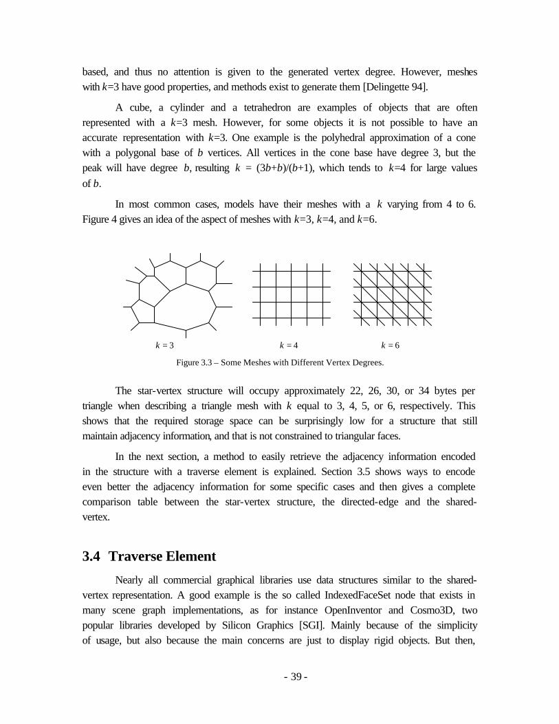
- 39 -
based, and thus no attention is given to the generated vertex degree. However, meshes with k=3 have good properties, and methods exist to generate them [Delingette 94].
A cube, a cylinder and a tetrahedron are examples of objects that are often represented with a k=3 mesh. However, for some objects it is not possible to have an accurate representation with k=3. One example is the polyhedral approximation of a cone with a polygonal base of b vertices. All vertices in the cone base have degree 3, but the peak will have degree b, resulting k = (3b+b)/(b+1), which tends to k=4 for large values of b.
In most common cases, models have their meshes with a k varying from 4 to 6. Figure 4 gives an idea of the aspect of meshes with k=3, k=4, and k=6.
Figure 3.3 – Some Meshes with Different Vertex Degrees.
The star-vertex structure will occupy approximately 22, 26, 30, or 34 bytes per triangle when describing a triangle mesh with k equal to 3, 4, 5, or 6, respectively. This shows that the required storage space can be surprisingly low for a structure that still maintain adjacency information, and that is not constrained to triangular faces.
In the next section, a method to easily retrieve the adjacency information encoded in the structure with a traverse element is explained. Section 3.5 shows ways to encode even better the adjacency information for some specific cases and then gives a complete comparison table between the star-vertex structure, the directed-edge and the shared-vertex.
3.4 Traverse Element
Nearly all commercial graphical libraries use data structures similar to the shared-vertex representation. A good example is the so called IndexedFaceSet node that exists in many scene graph implementations, as for instance OpenInventor and Cosmo3D, two popular libraries developed by Silicon Graphics [SGI]. Mainly because of the simplicity of usage, but also because the main concerns are just to display rigid objects. But then,
k = 3 k = 4 k = 6

- 40 -
whenever some mesh algorithm needs adjacency relations to run efficiently, a representation conversion is required.
Unfortunately, such conversions are indeed needed. The shared-vertex representation is a very low storage space solution for rigid objects, which is important when working with large real time environments that quickly slow down performance when memory starts to swap to disk.
However, the need of objects with a changing shape is growing, to allow, for example, smooth resolution changing in run time, local collision detection queries, and deformable spring meshes. Such algorithms often require a consistent data structure able to give and update adjacency relations in constant time. The star-vertex structure is a good candidate to overcome such difficulties. But still some interface layer to safely access and modify the structure is needed.
The proposed solution is to define a traverse element, or travel, that gives a common interface to access adjacency relations that can be implemented, using object-oriented techniques, to behave in the same way for any kind of data structure.
A travel is a structure-independent generalization of concepts from edge-based structures, as the edge-use [Weiler 1985], the dart [Lienhardt 1989], the half-edge [Mäntylä 1988], and the iterators defined in a recent C++ implementation [Kettner 1998]. Consider the mesh described in figure 3.4. This mesh is the same as in figure 3.2, and so its representation is also given by the table 3.1. In figure 3.4, a travel is graphically represented as an oriented edge, as the travel t. Note that each travel will be always adjacent to one, and only one, vertex, edge and face of the mesh. For example, travel t is adjacent to vertex v0, to edge { v0, v1 }, and to face { v0, v1, v2 }.
Figure 3.4 – Some traverse elements graphically represented.
Two operators are defined that can be applied to t: the nxt and the rot operators. The nxt operator, when applied to t, will return the travel that is adjacent to the next edge and vertex around the face that is adjacent to t. This operator permits to traverse the edges around a face. For example, in figure 3.4, t.nxt ≡ t1, t1.nxt ≡ t2, and t.nxt.nxt.nxt ≡ t.
v0
v1
v2
v3
v4
v5
t2
t1
s
t’
t

- 41 -
Similarly, the rot operator, when applied to t, will return the other travel that is adjacent to the next edge and face around the vertex that is adjacent to t. This operator gives the possibility to “rotate” around a given vertex. For example, in figure 3, we have that t.rot ≡ t’, and t’.rot.rot.rot ≡ t.
With these two operators defined the operator sym can be defined, which gives the symmetrical travel: t.sym ≡ t.nxt.rot ≡ s. And also their inverses: t.sym-1 ≡ t.sym, t.nxt-1 ≡ t.rot.sym, and t.rot-1 ≡ t.sym.nxt.
As the traverse element behaves exactly as an oriented edge, the reader can refer to the half-edge structure [Mäntylä 1988] for a detailed explanation of a very similar scheme of traverse operators.
Once the traverse element is equipped with operators to retrieve their current adjacent elements, it is possible to traverse freely through the structure, querying all adjacent relations. The following code indicates how to implement such a traverse element for the star-vertex structure, using a C++ notation:
class Travel { Vertex *v; // points the adjacent vertex of the travel int r; // indicates the adjacent edge of the travel // some operators and methods : Travel ( Vertex *vtx, int rot ) { v=vtx; r=rot; } Travel rot () { return Travel(v,(++r)%v->num_nb); } Travel nxt () { return Travel(v->nb[r].vtx,v->nb[r].nxt); } Travel sym () { return nxt().rot(); } float *pnt () { return &(v->x); } bool operator == ( Travel t ) { return v==t.v&&r==t.r; } };
The travel structure keeps a pointer to the current adjacent vertex v, and the index r. This index defines the pair in the neighborhood array of v which has vn, the vertex defining the current adjacent edge { v, vn } of the travel. Because of the implicitly stored counterclockwise order, the adjacent face is also defined. As an example, it is easy to verify that: Travel(v0,0).nxt() ≡ Travel(v1,3), and that Travel(v0,0).rot ≡ Travel(v0,1).
One consequence of using such a vertex-based structure is that faces are not explicitly stored. In this way, some algorithm to retrieve the faces is needed, for example, to render the represented mesh using a polygon based renderer as the OpenGL library. Such algorithms often need some mechanism to mark the traverse elements already visited. The following code shows how it is possible to use the nxt index of the Neighbor structure to mark elements, by adding two methods to the Travel structure:
void Travel::mark () { v->nb[r].nxt *= -1; } bool Travel::marked () { return v->nb[r].nxt<0; }

- 42 -
The mark is stored by setting the index to a negative value. Note however, that this implies to no more use the 0 index, and to pay attention to always consider the absolute value of the index. The following code gives an example of an algorithm that sends the faces of a mesh to an OpenGL renderer. It starts with any initial face, and then, by exploiting faces adjacency, the other faces are rendered:
render ( const StarVertexMesh& m ) { // initializes a stack with some travel: array<Travel> stack; stack.push( Travel(m.vertices[0],0) ); while ( !stack.empty() ) { Travel ti = stack.pop(); if ( ti.marked() ) continue; Travel t=ti; glBegin ( GL_POLYGON ); do { glVertex3fv ( t.pnt() ); if ( !t.marked() ) t.mark(); stack.push ( t.sym() ); t = t.nxt(); } while ( t!=ti ); glEnd (); }
Note that all faces of the mesh are sent to the renderer. In the case of a planar mesh like the one showed in Figure 3.2, the border of the polygon is also sent, but it will not be drawn as it will be considered a back-face because of the consistent orientations. Note also that faces need to be convex in order to be correctly handled by OpenGL.
Some strategies can be taken in order to avoid unmarking all previously marked traverse elements after each time such an algorithm is called. For example, each time an algorithm starts, it can determine if elements are considered marked when the used indices have a negative or a positive value. In this way, algorithms like the given render procedure can be repeatedly called, by alternating the indices markers to have positive or negative values. However, with this technique, it is not allowed to have an algorithm leaving the mesh “half-marked”.
The fact that faces are not explicitly stored would not slow down rendering, because nearly all systems work with optimized display lists of the polygons to render. Therefore, such traversal of faces would be done to update display lists only when the model topology changed. Moreover, the generation of display lists can make use of the encoded adjacent relations, to generate optimized “connected” lists, as for example, the triangle or quad strip schemes of OpenGL.

- 43 -
3.5 Analysis and Comparison
From section 3.2, the star-vertex structure takes approximately 10+4k bytes per triangle, considering that the mesh represented is composed of triangular faces. It is still possible to lower this storage space in some specific cases, and two simplifications for the given “general” star-vertex structure will be shown.
A first simplification can be done when the mesh to represent has a constant vertex degree for all vertices of the mesh. This implies that the pointer to an array of variable length is no more needed, and the same for the number of neighbors per each vertex. Doing so, 1 integer and 1 pointer per vertex can be economized, making an economy of 8 bytes per vertex, or 4 bytes per triangular face. The result is 6+4k bytes per triangle for this “uniform” star-vertex, that can only represent meshes with constant vertex degree.
Another type of simplification that reduces even more the required storage space can be done, but now loosing the constant time execution of the nxt operator. This simplification is done simply by taking out the nxt index of the Neighbor structure. This index is used to explicitly store the result of the nxt operator. If this index is no more used, then the nxt operator will take time O(dmax), where dmax is the maximum vertex degree encountered in the mesh being represented. This happens because a search among all edges incident to the neighbor vertex will be done, to find the one that correctly produces the result of the nxt operator. The implementation of the nxt operator would then look as the following :
Travel Travel::nxt () { Travel t (v->nb[r].vtx,0); while ( t.rot().v!=v ) t=t.rot(); return t; }
In this compact version, the structure will occupy 4⋅5⋅n bytes for the vertex structure, plus 4⋅k⋅n bytes for the list of neighbors, ending up with (4⋅5 + 4⋅k)n ≈ 10+2k bytes per triangle. It is also possible to have the structure with both the compact and the uniform simplifications, leading us to (4⋅3 + 4⋅k)n bytes = 6+2k bytes per triangle.
Note that in cases where memory usage is an issue, the compact versions of the structure will achieve very low storage space requirements. And the fact that O(dmax) time is required by the nxt operator can be acceptable if the mesh has low degree vertices.
Finally, table 2 shows a comparison of the data structures. The time required for the determination of the rot and nxt operators are listed. When these two operators are provided in constant time, all adjacent relations can be also retrieved in constant time.

- 44 -
Note also that the shared-vertex representation can give in constant time the nxt operator only if the structure guarantees coherent orderings, providing that the vertices indices of each face are sequentially stored. However, the rot operator requires some global search in the structure.
In order to be able to compare these structures, it was considered that they are representing triangle meshes. In this way, the m≈2n property was used to achieve the bytes per triangles number. However not all structures are limited to represent triangle meshes, as shown in the mesh type column.
As expected, the proposed structure can achieve very low memory requirements when k is small, even without counting the possible uniform or compact versions. For meshes with k greater than 5.5, the star-vertex structure will require more memory than the directed-edge, however, without being restricted to triangular faces.
bytes /∆ data structure
rot operator
time
nxt operator
time
mesh type
Any k k=3 k=4 k=5 k=6 general shared-vertex - O(1) - 22 22 22 22 22 triangle shared-vertex - O(1) ∆ 18 18 18 18 18
small directed-edge O(1) O(1) ∆ 32 32 32 32 32 star-vertex O(1) O(1) - 10+4k 22 26 30 34
uniform star-vertex O(1) O(1) deg cte 6+4k 18 22 26 30 compact star-vertex O(1) O(dmax) - 10+2k 16 18 20 22 minimal star-vertex O(1) O(dmax) deg cte 6+2k 12 14 16 18
Table 3.2 – Comparison of the several data structures. In the rot operator column, “-” indicates that its computation is not possible with only a local search in the data structure. In the mesh type column, “-” indicates that there are no restrictions on the mesh to be represented. Variables k and dmax represent, respectively, the mean and the maximum vertex degree of the mesh.
3.6 Two Examples of Applications
The star-vertex structure is presented in this thesis like an isolated result due to the very interesting characteristics achieved. Currently, it is being integrated for many different purposes in our graphical simulation softwares, as for instance, for research on multi resolution of deformable bodies and on path planning. Figures 3.5 and 3.6 exemplify some first results obtained by using a similar structure to the star-vertex, which I have previously developed, and which I am now porting to the star-vertex optimized format.

- 45 -
Figure 3.5 – An example of a deformable surface using multi-resolution techniques to adapt itself only around the region having the contact with the falling ball. In order to efficiently refine the surface, constant time access of adjacent elements plays a key role. The dynamical system used is based on a standard spring-mass system.
Figure 3.6 - The image illustrates the computation of a collision-free path among obstacles. An exact cell decomposition method is used, based on a constrained Delaunay triangulation. Once we have access to all adjacency information, a free path is easily generated just by walking through adjacent free faces.
3.7 Chapter Conclusion
A new scalable data structure was presented for storing planar meshes, which has interesting properties that can be exploited in order to obtain very low storage space usage, still obtaining adjacency relations in constant time.
The structure is not constrained to triangular faces and stores adjacency information in a vertex-based organization. This implies that the storage space required is direct proportional to the mesh vertices’ degrees (number of edges incident to vertices). When these degrees are small, lower memory requirements are achieved, comparing to other structures. Models with low vertices degree are commonly used, and algorithms can be designed to optimize general meshes.

- 46 -
A traverse element was also shown serving as a high level interface to retrieve the encoded adjacency information. Such element hides specific optimizations or simplifications on the structure implementation, and can be also used as a parameter to eventual topological operators. Such architecture can even permit some self-adaptability of the data structure during run time, according to the way the structure is being used.
Such properties make the star-vertex structure a good candidate to be implemented as a standard node in a scene-graph library for real time virtual environment simulations. It allows safe access to adjacency relations without the need of representation conversions, while maintaining low storage space requirements.
.

- 47 -
4 Modeling Smart Objects
This chapter presents the feature modeling approach of interactive objects proposed in this dissertation and the smart object description.
The first sections start by describing the concept of interaction features, together with their classification and definition. Then, the developed smart object modeler (somod) is presented, which is a system incorporating the proposed approach to model the functionality and interactivity of objects. Some examples of modeled objects are shown and explained.
4.1 Introduction
The necessity to model actor-object interactions appear in most applications of computer animation and simulation. Such applications encompass several domains, as for example: virtual autonomous agents in virtual environments, human factors analysis, training, education, virtual prototyping, and simulation-based design. A good overview of such areas is presented by [Badler 1997].
Commonly, simulation systems approach actor-object interactions by programming them specifically for each case. Such approach is simple and direct, but does not solve the problem for a wide range of cases.
Another approach, not yet solved, is to use recognition, planning, reasoning and learning techniques in order to decide and determine the many manipulation variables during an actor-object interaction. The actor’s knowledge is then used to solve all possible interactions with an object. Moreover, this top-down AI approach should also address the problem of interaction with more complex machines with some internal functionality, in which case information regarding the object functionality must be provided.
Consider the simple example of opening a door: the rotation movement of the door must be provided a priori. Following the top-down AI approach, all other actions should be planned by the agent’s knowledge: walking to reach the door, searching for the

- 48 -
knob, deciding which hand to use, moving body limbs to reach the knob, deciding which hand posture to use, grasping, turning the knob, and finally opening the door. This simple example illustrates how complex it can be to perform a simple agent-object interaction task.
To overcome such difficulties, I propose a bottom-up approach that is to include within the object description, more useful information than only intrinsic object properties. Using feature modeling concepts, it is possible to identify all types of interaction features in a given object, and include this information as part of the object description.
A graphical interface program was developed to permit the user to interactively specify all different features in the object, defining its functionality, its available interactions, etc. Objects modeled with their interaction features description, are called as smart objects. The developed smart object modeler application is called somod.
The adjective smart has been widely used in different contexts. For instance, [Russel 1995] and [Pentland 1995] discuss interactive spaces instrumented with cameras and microphones to perform audio-visual interpretation of human users. This capacity of interpretation made them smart spaces.
In the scope of this thesis, an object is called smart when it has the ability to describe in details its functionality and its possible interactions, being also able to give all the expected low-level manipulation actions. This can be seen as a mid term classification between reactive and intelligent behaviors. A smart object does have reactive behaviors, but more than that, it is also able to provide the expected behaviors from its “users”, so that this extra capability makes it to achieve the quality of smart.
Note that the term “user of an object” is used to refer to an autonomous actor, an avatar, or a real person immersed in the VE with VR devices. In this last case, the user is performing a direct interaction with the object. Although this thesis is mainly concerned with actor-object interactions, some experiments about the direct interaction with smart objects is done (chapter 7), so that the term “user” is used to refer to any kind of users.
Different simulation applications can then retrieve useful information from a smart object to accomplish desired interaction tasks. The main idea is to provide smart objects with a maximum of information to attend different possible applications for the object. A parallel with the object oriented programming paradigm can be made, in the sense that each object encapsulates data and provides methods for data access. There is a huge literature about Object Oriented Design; an introduction to the theme can be found in [Booch 1991].

- 49 -
Applications using smart objects will have their own specific smart object reasoning module, in order to retrieve only the applicable object features for their specific needs. These concepts are published in two previous works [Kallmann 1998] [Kallmann 1999a], and will be detailed in the following sections.
4.2 Related Work
Object interaction in virtual environments is an active topic and many approaches are available in the literature. However, in most cases, the concerned topic is the direct interaction between the user and the environment [Hand 1997].
Suppliers of CAD systems are starting to integrate some simulation parameters in their models [Berta 1999]. The knowledgeware extension of the [Catia] system can describe characteristics like costs, temperature, pressure, inertia, volume, wetted area, surface finish, formulas, link to other parameters, etc; but still no specific considerations are done to define objects functionality or interactivity.
Actor-object interaction techniques were first specifically addressed in a simulator based on natural language instructions using an object specific reasoning (OSR) module [Levinson 1994a] [Levinson 1994b]. The OSR keeps a relational table informing geometric and functional classification of objects, in order to help the interpretation of natural language instructions. With such information, it is possible to interpret and expand given text instructions [Geib 1994a] [Geib 1994b].
Some interaction information is also kept by the OSR module: for each object graspable site, the appropriate hand shape and grasp approach direction. This set of information is sufficient to decide and perform grasping tasks, but no considerations are done for the interaction with more complex objects. In particular, [Webber 1995] identify the limited perception of actors as a main limitation to correctly interpret text instructions, resulting in a poor knowledge construction. Smart objects can overcome such difficulties.
The smart object description is much more complex, based on interaction plans, permitting to synchronize movements of object parts with the actor’s hand, and to model the functionality of objects.
Interactive plans are defined using a specific simple programming language. In another direction, some works have been done in order to link language to modeling [Paoluzzi 1995], and towards a definition of a standard and data structure-independent interface to model geometric objects [Bowyer 1995].

- 50 -
A key concept in smart objects is that they contain their own semantic and interaction information. A recent game [TheSims] also use this object-oriented approach to describe interaction with objects. In this game, the user creates and coordinates a family of actors and their day life activities, which include some interaction with objects. Another “object oriented system” is proposed by [Okada 1999], where objects can be composed with many boxes which have input and output connectors that can be linked to achieve different functionalities. However, no specific considerations regarding actor-object interactions are presented.
A typical application for smart objects is to train complex machines usage in a virtual environment. Although many simulation systems are proposed in the literature (for instance: [Luckas 1997]), no special considerations are done regarding object interaction. An interesting system is proposed by [Johnson 1997], where a virtual human agent teaches users how to correctly operate machines in many situations in an interactive application. His focus is on the system description and no specific techniques to model actor-object interactions are presented.
None top-down AI approaches were found specifically focusing the problem of solving general actor-object interactions. Most of the concerns are related to sub-problems, as for the specific problem of grasping. For instance, from the robotics area, a classification of hand configurations for grasping is proposed by [Cutkosky 1989]. Also [Huang 1995] proposes an algorithm for the autonomous actor’s decision of manipulation details (as the hand shape to use) for grasping.
From the robotics domain, planning algorithms are able to define collision-free paths for articulated structures [Koga 1994] [Simeon 2000]. Although realistic results can be obtained, the computational cost today is too high for interactive simulations.
Such algorithms focus on specific sub-problems, and an integration of all of them in a single system is a challenge. However, some of them can be integrated and used in an animation system based on smart objects. For instance, a specific smart object reasoning module can refuse a proposed hand shape for a manipulation, and determine a more convenient one, according to its own reasoning processes.
4.3 Feature Modeling of Interactive Objects
Feature modeling is an expanding topic in the engineering field [Barwick 1993]. The word feature conjures up different ideas when presented to people from different backgrounds. A simple general definition, suitable for our purposes, is “a feature is a region of interest on the surface of a part” [Pratt 1985].

- 51 -
The main difficulty here is that, in trying to be general enough to cover all reasonable possibilities for a feature, such a definition fails to clarify things sufficiently to give a good mental picture.
From the engineering point of view, it is possible to classify features in three main areas: functional features, design features and manufacturing features [Barwick 1993]. As we progress from functional features through design features to manufacturing features, the quality of detail that must be supplied or deduced increases markedly. In the other hand, the utility of the feature definitions to the target application decreases. For example, manufacturing features of a piece may be hard to describe and have little importance while really using the piece. A similar compromise arises in the smart object case. This situation is depicted in figure 4.1 and will be explained later.
A huge literature is available for the feature modeling technique in the scope of engineering. A good coverage of the theme is done by [Shah 1995].
4.3.1 Interaction Features
In the smart object description, a new class of features for simulation purposes is proposed: interaction features. In such context, a more precise idea of a feature can be given as follows: all parts, movements and descriptions of an object that have some important role when interacting with an actor.
For example, not only buttons, drawers and doors are considered as interaction features in an object, but also their movements, purposes, manipulation details, etc.
Interaction features can be grouped in four different classes:
• Intrinsic object properties: properties that are part of the object design, for example: the movement description of its moving parts, physical properties such as weight and center of mass, and also a text description for identifying general objects purpose and the design intent.
• Interaction information: useful to aid an actor to perform each possible interaction with the object. For example: the identification of interaction parts (like a knob or a button), specific manipulation information (hand shape, approach direction), suitable actor positioning, description of object movements that affect the actor’s position (as for a lift), etc.
• Object behavior: to describe the reaction of the object for each performed interaction. An object can have various different behaviors, which may or may not be available, depending on its state. For example, a printer object will have the “print” behavior available only if its internal state variable “power on” is true. Describing object’s behaviors is the same as defining the overall object functionality.

- 52 -
• Expected actor behavior: associated with each object behavior, it is useful to have a description of some expected actor behaviors in order to accomplish the interaction. For example, before opening a drawer, the actor is expected to be in a suitable position so that the drawer will not collide with the actor when opening. Such suitable position is then proposed to the actor during the interaction.
This classification covers the needed interaction features to simulate common actor-object interactions. Still, many design choices appear when trying to specify in details each needed interaction feature.
The most difficult features to specify are those relative to behaviors. Behavioral features are herein specified using pre-defined plans composed with primitive behavioral instructions. This has shown to be the most straightforward approach because then, to perform an interaction, the actor will only need to “know” how to interpret such interaction plans.
In the smart object description, a total of 8 interaction features were identified, with the intention to make the most simple classification possible. These interaction features are described in table 4.1.
Feature Class Data Contained
Descriptions Object Property Contains text explanations about the object, organized by different types: semantic properties, purposes, design intent, and any general information.
Parts Object Property Describes the BRep of each component part of the object, their hierarchy, and other information as mass, center of mass, and a positioning matrix in relation to the object’s skeleton root.
Actions Object Property Actions are specially used to define movements, but also to define any other changes that the object may undertake, as color changing, texture, etc. Actions are defined independently of any parts.
Commands Interaction Info. Commands are used to parameterize and associate to a specific part the defined actions. For example, the translation movement of a drawer is an intrinsic property of the object and is modeled as an action. The commands “open” and “close” will then permit to parameterize the translation according to each interaction.
Positions Interaction Info. General positions needed to specify interactions are defined here relatively to the object’s skeleton root. Such positions are then referenced from the behavioral plans to suggest for the actors suitable positions to be used during interactions.
Gestures Interaction Info. Gestures are considered to be any movement to suggest to an actor. Hand shapes and locations for grasping and manipulation are defined here, also parameters to specify the actor to sit, or to apply any pre-recorded motion are defined here and later referenced from the behavioral plans.

- 53 -
Variables Object Behavior Variables are generally used in the behavioral plans, but specially used to define the state of the object. The state of an object is a key information in the description of the object’s functionality, which is done with the behavioral plans.
Behaviors Obj./Actor Behavior Behaviors are defined with plans composed with primitive instructions. Such plans can check or change the states of the object, trigger commands and gestures, call other plans, etc; and specify both object behaviors and expected actors’ behaviors. These plans form a simple scripting language that is used for the actor-object communication during interactions.
Table 4.1 – The eight types of interaction features that are used in the smart object description.
4.3.2 Interpreting Interaction Features
Once a smart object is modeled, a simulation system will be able to load it and animate it in the VE. For this, the simulator will need to implement a smart object reasoning module, that will correctly interpret the behavioral plans to perform interactions. For example, a VR application in which the user wears a virtual glove to press a button of a smart object will not make the same use of proposed hand shapes.
There is a trade-off when choosing which features to be considered in an application. As shown in figure 4.1, when taking into account the full set of object features, less reasoning computation is needed, but less general results are obtained. As an example, minimum computation is needed to have an actor passing through a door following strictly a proposed path to walk. However, such solution would not be general in the sense that all agents would pass the door using exactly the same path. To achieve better results, external parameters should also take effect, as for example, the current actor emotional state.
Figure 4.1 – The choice of which interaction features to take into account is directly related to many implementation issues in the simulation system.
Note that a realistic result is a context dependent notion. For example pre-defined paths and hand shapes can make an actor to manipulate an object very realistically. However, in a context where many actors are manipulating such objects exactly in the same way, the overall result is not realistic.
Interaction Info.
Less Computation, Easier Usage - Less General, Less Adaptability
Agent Behaviors Object BehaviorsObject Properties

- 54 -
Interaction plans form the interface between stored object’s features and the application specific smart object reasoning. Figure 4.2 illustrates the connection between the modules. The simulation program requires a desired task to be performed. The reasoning module will then search for suitable available behaviors in the smart object. For any selected behavior, the reasoning module follows and executes each instruction of the behavior plan, retrieving the needed data from the smart object representation.
Figure 4.2 - Diagram showing the connection between the modules of a typical smart object application. Arrows represent function calls.
When a task to perform becomes more complex, it can be divided into smaller tasks. This work of dividing a task into sub-tasks can be done in the simulation program or in the reasoning module. In fact, the logical approach is to leave the reasoning module only to perform tasks that have a direct interpretation from the Smart Object behaviors. Then, additional layers of planning modules can be built according to the simulation program goal.
Another design choice appears while modeling objects with too many potential interactions. This issue is related to definition of the component parts of a composed object. In such cases, in order to exercise a greater control over the interactions, it is possible to model the object as many independent smart objects, each one containing only basic interactions. For example, to model an actor interacting with a car, the car can be modeled as a combination of different smart objects: car door, radio, and the car panel. In this way, the simulation application can explicitly control a sequence of actions like: opening the car door, entering inside, turning on the radio, and starting the engine, thus permitting more personalized interactions. On the other hand, if the simulation program is concerned only with traffic simulation, the way an agent enters the car may not be important. In this case, a general behavior of entering the car can be encapsulated in a single smart object car.
Later in this chapter the example of modeling a smart lift is given and two approaches are shown. In one approach, a main interaction plan “enter” is modeled which details all steps of taking the lift to go to the other floor. In a second approach, in order to accomplish the same interaction, a sequence of plans needs to be selected by the simulator: “press”, “go in”, “go out”, etc.
The smart object approach introduces the following main characteristics in a simulation system:
Object Reasoning Module
Ask for some task
Search suitable interaction plans
Simulation Program
Smart Object

- 55 -
• Decentralization of the animation control. Object interaction information is stored in the objects, and can be loaded as plug-ins, so that most object-specific computation is released from the main animation control.
• Reusability of designed smart objects. Not only by using the same smart object in different applications, but also to design new objects by merging any desired feature from previously designed smart objects.
• A simulation-based design is naturally achieved. The designer can take control of the loop: design, test and re-design. A designed smart object can be easily inserted into a simulation program, to get feedback for improvements in the design.
4.3.3 Implementation Issues
A library composed of C++ classes has been developed to interpret smart object plans. A main class SmartObj keeps a list of SmartObjUser classes, which knows how to correctly interpret each instruction in the plan. The SmartObjUser class is a base class that interprets all object related instructions, but the user related instructions call pure virtual methods, which have to be implemented for each specialized type of user. For instance, different kinds of users can be implemented: an actor, an avatar, interaction with only a pointing device, or with VR devices.
In the scope of this thesis, three types of users were implemented, inheriting the SmartObjUser class: the first type simply ignores all user-related instructions, permitting to animate objects independently. A second type implements the virtual actor user (see next chapter), and a last type implements a real user wearing a data glove (see chapter 7).
4.4 Somod Description
The somod application was developed specifically to model smart objects. Somod permits to import BRep models of the component parts of an object, and then specify interactively all needed interaction features. All the features are defined using a graphical user interface. Even for the definition of the behavioral plans, a specific dialog box was designed that guides all possible parameters to specify for each primitive instruction. In addition, some graphical programming techniques are used in order to graphically specify plans using a finite state machine graph.
4.4.1 Software Platform
Somod was initially developed based on the Motif user interface library, with some dependency on AgentLib under SGI with the Irix system. With the evolution of the

- 56 -
software in the lab, and the tendency to move to PC platforms, somod completely changed to use platform-independent libraries. The actual version of somod is written in C++, and uses the Fast and Light Toolkit [FLTK] for the graphical user interface programming. The FLTK library has shown to be very easy and powerful to use and is available free of charge for nearly all computer platforms.
As graphics library, OpenInventor is used. OpenInventor is the best available graphics library for the purpose of high level modeling. The built-in manipulators classes permit to easily manipulate 3D objects with a 2D mouse as input device. This library is available from [SGI] and [TGS] for different computer platforms, and some initiatives exist to propose an open source version of OpenInventor. For instance, [SGI] has released the source code of OpenInventor to the Linux platform for free, and the same code has been already adapted to the Microsoft Windows platform.
For the definition of hand shapes in somod, an internal module of DodyLib is used, which provides the deformation of a hand skin envelope, based on the actual skeleton joints. This module was developed by Laurent Moccozet [Moccozet 1997].
Somod is currently used only in SGI machines, but due to the platform-independent nature of its libraries, it can be ported to other computer systems.
4.4.2 Defining Object Properties
The main window of somod is shown in figure 4.3. Features are organized by type, and for each type, a list of features can be defined. The main window permits to manage these lists in a unified way. For each feature, the specific parameters can be edited with the corresponding specialized dialog box. In figure 4.3 the list of parts is shown. Windows in somod have two colors: the blue ones are those that can work in parallel, and the yellow ones are dialogs that block all other windows while opened.
Figure 4.3 – The main window of somod, showing a list of interaction features of the selected type. When Edit is pressed, the specific dialog box to edit the parameters of the selected feature appears. Menus are used to access extra functionalities.

- 57 -
An object description dialog contains simple text entries where the user can type text descriptions. The two main fields used are to describe a semantic name for the object, and to describe overall object characteristics. These definitions can then be retrieved by simulators for any kind of processing.
The dialog box to define the parameters for each part is shown in figure 4.4. Among other parameters, it is possible to specify the geometry files of the part and their hierarchy (i.e., the skeleton). Also, the positioning of each part can be done interactively using the OpenInventor manipulators.
The same technique of using manipulators is adopted to define the movement actions that can be applied to the object. For example to define a translation, the user select an object’s part and a manipulator, being able to displace the part from its original position. The transformation movement from the initial position to the user selected position is then saved as an action. Note that actions are saved independently of parts, so that they can be later parameterized differently (defining commands) and applied to many different parts.
Figure 4.4 – Defining the specific parameters of a drawer. The drawer is a part of the smart object desk, which contains many other parts. The image shows in particular the positioning of the drawer in relation to the whole object.
4.4.3 Defining Interaction Information
The definition of commands is done with the simple dialog box shown in figure 4.5. Commands fully specify how to apply an action to a part and will be directly referenced from the behavioral plans whenever a part of the object is required to move.

- 58 -
Figure 4.5 – The command editor dialog box permits to parameterize actions and to associate an action to part.
Positions are defined using the dialog box shown in figure 4.6. Positions can be used for any purpose and can specify also a direction vector. It is possible to set their position interactively, using the widgets in the dialog box, or directly in the 3D graphical window using manipulators. Each position (as each feature) is identified with a given name for later referencing in the interaction plans.
Note that all features that are related to graphical parameters can be defined interactively, what is important in order to see their location in relation to the object. Positions are defined in relation to the object skeleton’s root, so that they can be transformed to the same reference frame of the actor whenever is needed, during the simulation. Note that smart objects can be loaded and positioned anywhere in the virtual environment.
Figure 4.6 – Positions can be defined for any purpose. In the image, many different positions (and orientations) are placed to propose possible places for actors to walk when arriving from any of the door sides.
Gestures are the most important interaction information. Gestures parameters are defined in somod and proposed to actors during an interaction. We use the term gesture to refer to any kind of motion that an actor is able to perform. The most used gesture is to move the hand towards a position in space in order to press a button (a push movement),

- 59 -
or to grasp something. The possible parameters for the gesture feature are shown in figure 4.7.
Figure 4.7 – Gestures parameters dialog box. Depending on the action algorithm chosen, some parameters may be used differently. In the image, the action algorithm push is selected.
For each gesture, a hand shape, a positioning matrix for the hand, and the desired action algorithm must be supplied (see figure 4.8). The action algorithm here refers to the actions of AgentLib. Depending on the selected algorithm, some extra parameters can be used or not. For example, three main actions are often used: reach, push, and sit.
The used action algorithms depend directly on the capabilities of the animation system, so that they are configurable using descriptive files. When somod starts, a special folder is scanned where files define each supported action algorithm in the target animation system, and also some pre-defined hand shapes. The developed simulation system (ACE) is based on AgentLib, and is the subject of the chapter 6. AgentLib provides already the action “reach”. Additionaly, the actions “push” and “sit” where developed and are the subject of chapter 5.
In short, the action reach will only animate an actor’s arm to put its hand in a given location. Depending on the state of extra parameters, after the hand has reached the defined goal, the actor can then take or put an associated part. The push action differs in two aspects: it is able to animate the whole actor’s body in order to achieve better postures, and the actor’s hand can then follow a movement of an associated part in order to simulate the movement of opening, pressing, pushing, etc. The sit action, will define the actor to sit, using a target position defined as a path to follow. All these actions use inverse kinematics as the motion motor. Additionally, it is also possible to define a pre-defined motion to be played as a keyframe.

- 60 -
Figure 4.8 – The left image shows a hand shape being interactively defined. The right image shows all used hand shapes being interactively located with manipulators.
4.4.4 Defining Behaviors
As already explained, behaviors are defined using pre-defined plans formed by primitive instructions. It is difficult to define a closed and sufficient set of instructions to use. Moreover, a complex script language to describe behaviors is not the goal. The idea is to keep a simple format with a direct interpretation to serve as guidance for reasoning algorithms, and which non-programmers can create and test.
A first feature to recognize in an interactive object is its possible states. States are directly related to the behaviors one wants to model for the object. For instance, a desk object will typically have a variable state for its drawer which can be assigned two values: “open”, or “close”. However, depending on the context, it may be needed to consider another midterm state value. Variables are used to keep the states of the object and can be freely defined by the user to approach many different situations. Variables are defined by assigning a name and an initial value, and can be used for many purposes from the interaction plans.
Interaction plans are defined using a specific dialog box (figure 4.9) which guides the user through all possible primitive instructions to use. In addition, a help window is available (figure 4.10) to describe each available instruction.
The following key concepts are used for the definition of interaction plans:
• An interaction plan describes both the behavior of the object and the expected behavior of its user. Instructions that start with the word “user” are instructions that are proposed to the user of the object. Examples of some user instructions are: UserGoto, UserDoGest, UserAttachTo, etc. For a complete list of the available primitive instructions, see section 10.1 in the appendix.

- 61 -
• In somod, an interaction plan is also called as a behavior. Many plans (or behaviors) can be defined and they can call each other, as subroutines. Like programming, this enables building complex behaviors based on simpler behaviors.
Figure 4.9 – The dialog box used to define interaction plans. Menu-buttons are used to list all possible instructions to use, and for each instruction, the possible parameters are listed in additional menu-buttons. Also, each instruction has a built-in help description that can be automatically shown in the help window (see also figure 4.10).
Figure 4.10 – The help window. A description of each primitive instruction is available to use during the definition of the interaction plans.
• There are three types of behaviors (or plans): private, object control, and user selectable. Private behaviors are kept only to be called from other behaviors. An object control behavior is a plan that is interpreted all the time since the object is loaded in a virtual environment. This enable to have objects acting like agents, for example sensing the environment to trigger some other behavior, or to have a continuous motion as for a ventilator. Object control behaviors cannot have user-related instructions. Finally, user selectable behaviors are those that can be selected by users, in order to perform a desired interaction.
• Selectable behaviors can be available or not, depending on the state of specified variables. For example for a door, one can design two behaviors: to open and to close the door. However, only one is available at a time depending on the open state of the door.

- 62 -
The instruction CheckVar is used to control the availability of behaviors and is exemplified in figures 3.9 and 3.10. When the CheckVar test is false the behavior is not available for selection (from the simulation system) and also it makes its interpretation to stop.
The behavior showed in figure 4.9 uses the state_passing variable to avoid closing the door while agents are still passing. Some instructions were specifically designed to cope with more than one actor interacting with the object at the same time. For instance, the UserGetClosest instruction is used to detect in which side of the door the actor is, so that the correct positions are then given to make it pass the door. The full file description of this automatic door example, coping with many actors at a same time, is shown in the section 10.2.1 (appendix). Figure 4.11 shows two agents passing through the door.
Figure 4.11 – Two actors passing through an automatic door. The used interaction plans can correctly manage more than one actor interaction at the same time.
Multi-Actor Interaction with a Same Object
Whenever interaction plans are designed, it should be taken into account if the object will need to interact with many agents at a same time or not. The interaction plans are responsible to correctly call the available primitive instructions for synchronization. If synchronization is not ensured by the interaction plans, the simulator application will not be able to guarantee a correct result.
Most of the time, variables are used to keep the number of agents currently interacting with the object, and based on that, different strategies can be taken. Note that it is not possible to predict a global behavior for all kind of objects when a multi agent interaction is required. For instance, in the automatic door example, up to three actors can pass the door together at a same time, however, to press the calling button of a lift only one actor at a time can access the button and press it.

- 63 -
As an example, the automatic door shown in figure 4.11, uses two strategies to synchronize up to three actors passing the door at the same time. One strategy is to count the number of actors actually passing through the door, in order to forbid closing the door if this number is not zero. Another used strategy is to define three different positions on both sides of the door, which are then given as walking targets in parallel for the actors, without generating collision of paths.
Graphical State Machines
Somod plans are very simple to use to describe simple interactions and functionalities. They can still cope with much more complex cases, but then plans start to get more complex to design. It is like trying to use a specific purpose language to solve any kind of problems.
As an example, consider the case of modeling a two-stage lift where actors can take. Such a lift is composed of many parts: doors, calling buttons, the cabin, and the lift itself. These parts need to have synchronized movements, and many details need to be taken into account in order to correctly control actors interacting with the lift.
To simplify modeling the behaviors of such complex objects, somod has a graphical dialog box to graphically design finite state machines. The proposed solution is to start designing basic interaction plans for each components of the lift, using the standard behavior editor (figure 4.9). Then, when the components have their functionality defined, the state machine window is used, permitting to define the states of the whole object lift, and the connections between the components.
Figure 4.12 shows a first example of using this graphical window in the case of the lift. The user has first designed the plans for the functionality of each component part in particular. For example, there are behaviors to open and close each door of the lift, to press each calling button, to move the cabin, and so on. The description file generated with this lift example is available in the appendix, section 10.2.3.
Then, the user opens the graphical state machine editor to design the functionality of the lift as a whole. A first simple example is considering that the lift can have only two states: floor_1 and floor_2. When the lift is in floor_1, the only possible interaction is enter_12, that will call a behavior which calls the full sequence of instructions to perform the full interaction: pressing the calling button, opening the door, entering inside, closing the door, move the cabin up, opening the other door, and going out. This simple state machine example is showed in figure 4.12.

- 64 -
Figure 4.12 – A state machine for a lift functionality where all interaction during the process of taking the lift are programmed inside plans enter_12 and enter_21. In the image, the double circle state is the current state, and the rectangular boxes show the interaction needed to change of state. For example, to change from floor_1 to floor_2 state, interaction enter_12 is required.
Designed state machines are automatically translated into interaction plans so that, from the simulator point of view, all behaviors are treated as plans. When the smart lift is loaded in a simulation environment, the created available behaviors can then be selected. A drawback of this simple state machine is that the single interaction of entering the lift can be very long, giving no options to the actor in the middle. A more complex solution is given in Figure 4.13.
Figure 4.13 shows a more complex state machine that models the functionality of the lift by taking into account possible intermediate states. In this case, the actor needs to select, step by step, a sequence of interactions in order to take the lift to the other floor. Figure 4.14 shows some snapshots of the animation sequence of an actor entering the lift.
Figure 4.13 – A more complex state machine for the lift where intermediate states are considered. Additionally, behaviors are associated with each state to be triggered whenever the object enters that state.

- 65 -
Figure 4.14 – An actor entering the smart lift.
This lift model can be much more complex in order to cope with many actors at the same time, entering from any floor, etc. The lift model has been extended in order to correctly cope with up to three actors entering from each floor at a same time. However, it is difficult to evaluate if the programmed behaviors can correctly solve all possible combination of cases. Moreover, it is possible to find examples where avoiding a deadlock situation would be difficult. For example, a deadlock can easily occur when trying to solve the classical problem of simultaneous access of resources that is called the dining philosophers [Andrews 1991].
When an actor selects an interaction plan, a new process is opened in order to interpret this plan. This process can be seen as the actor skill to interact with objects, and is part of the smart object reasoning module. The issue of correctly interpreting plans in parallel is discussed in chapter 5.
4.4.5 Templates
Another utility available in somod is to load template objects. The idea is that any pre-modeled smart object can serve as a template to model new smart objects. A specific window to load templates was designed permitting to scan directories containing smart objects and to choose the desired features to import (figure 4.15).

- 66 -
Figure 4.15 – The template loader dialog box. This window permits to scan a directory with pre-modeled objects and components, visualize their internal features, and import any selected set of features.
The template loader window can import any kind of features from other smart objects. Many of the features have dependencies on other features, and these dependencies are all tracked and coherently loaded. In addition, names are automatically updated whenever conflicts with previously created names appear. Each time features are imported, the user can inspect and adapt the results, using the main window.
The template loader window associated with the graphical state machine editor forms an effective way of definition and reuse of object interactivity and interaction. Sets of components can be maintained in proper folders in order to be easily imported and connected, testing different combination of components to compose a whole object.
For example, a set of different types of door can be defined, each one having a different geometry or functionality, as double or single panels, center or side opening, translation or rotation opening, etc. These doors can then be easily imported to compose, for instance, the lift.
4.5 Somod Extensions
Somod has been used to model smart objects for different purposes. Some times objects have simple geometry but a lot of semantic information, and some times objects simply don’t offer interaction, and somod is used only, for instance, to define relative positions around the object for collision avoidance.
Somod is flexible in the sense that it permits the user to define only the desired features, relative to the object, that can be used later for any purpose. For example, one

- 67 -
can use somod to model a complete set of hand shapes (like the one proposed by [Cutkosky 1989] ) to use for approaching different grasping configurations.
When modeling more complex behaviors, the simplicity of the available set of primitive instructions may not be sufficient. The extension to connect with a high-level and complete interpreted language was integrated in somod. The used language is Python [Lutz 1996], so that python commands can be stored in the plans with the instruction PythonFunc (see appendix section 10.1).
To make use of the Python extension, the simulator system must be able to interpret python scripts, and this is the case of the simulator developed, which is the topic of chapter 6. Python is a very powerful language, available for nearly all platforms, and the source code is available for free. There is even a Java module that is able to interpret Python, opening the possibility to interpret Python scripts in standard web browsers.
For the sake of simplicity, somod uses a simple ascii text file format to save modeled smart objects (see appendix section 10.2). No special standards were used, but conversion to other file formats can be easily done, as for instance to a XML format.
Smart objects can also be described using a VRML syntax. However, it is not possible to fully translate interaction plans into VRML nodes. Standard VRML nodes only provide basic sensors and movements, so that external Java scripts would need to be used.
Moreover, browsers that load and animate VRML scenes don’t provide an agent environment with actors being animated and ready to interact with objects. Note however, that some efforts have been done to create virtual human animations using Java and VRML [Babski 2000]. A major problem of such systems is the much lower frame rates achieved, as Java is an interpreted language.
A simple translator from the smart object format to an animated and interactive VRML scene was developed, however with several limitations. Only simple behaviors can be correctly translated, and interaction is done only using mouse clicks. Figure 4.16 shows a smart object in a VRML format loaded in a web browser. In this example, whenever the user clicks on a drawer, the drawer will open or close. This example uses only standard VRML nodes.

- 68 -
Figure 4.16 – A smart object translated into a VRML file can be loaded and animated in a VRML browser.
4.6 Chapter Conclusion
In this chapter, the following topics were stressed: the feature modeling concepts used to model interactive objects, the smart object description, and the implementation issues of somod. In addition, examples of modeled objects were presented and discussed.
The most important aspect of the smart object description is the fact that any user of the object can ask for a list of available interactions, which is generated in run time, depending on the current state of the object. This list of possible interactions is the communication language between actors and objects, forming a behavioral interface to coherently manage any kind of users interacting with objects at a same time.
The next chapter explains the details and implementation issues related to the interpretation of interaction plans, and chapter 6 exposes the simulator system (ACE) that contains all such capabilities to simulate actor-object interactions.

- 69 -
5 Interpreting Interaction Plans
This chapter exposes the solutions adopted to overcome two main problems that appear during the interpretation of interaction plans: synchronization of many plans interpreted in parallel, and the motion control of actors to perform manipulation instructions.
The whole process from the high level interpretation of behaviors to the low level control of primitive actions and motions is explained. In addition, the synchronization rules adopted, and their limitations are also discussed.
5.1 Introduction
Given a set of instructions, i.e., an interaction plan, there are some strategies to consider in order to correctly animate the actor’s skeleton accordingly.
A first issue is how to synchronize plans that are interpreted in parallel. Note that, in the scope of this thesis, interaction plans can dictate the behaviors of both actors and objects. One can see an interaction plan as a program that runs in an independent process, and that must access resources from actors and objects.
The many synchronization problems involved have a direct relation with the concurrent programming area [Andrews 1991]. In this way, standard techniques can be used: barriers, flags, etc. A simple synchronization rule to activate and block the many processes interpreting plans is adopted and is discussed in section 5.3, together with the many related issues.
Another key issue is the animation of the virtual actor interacting with objects, i.e., how to correctly animate the actor’s skeleton according to a behavioral instruction. In most of the animation cases, a method to define a realistic skeleton posture, given a desired location for the actor’s hand is required. From now on, this specific problem will be referred to as the reaching problem.

- 70 -
The movement control of virtual actors, and specifically the reaching problem, is a key issue in many areas, specifically for human factors analysis [Stanney 1998], and ergonomics [Wang 1998], in the scope of many different applications.
Real time inverse kinematics is a key component of any human modeling system, allowing to directly approach the reaching problem. Mechanisms with more than six degrees of freedom (DOF) are considered redundant and thus some strategies to control the obtained result must be taken. In section 5.4 the adopted strategies in this work are explained.
5.2 Related Work
The parallel interpretation of plans or behaviors is an issue that appears in many behavioral animation systems. One specific structure to define parallel programs for describing behaviors is the parallel transitions network (PaTNets) [Granieri 1995] [Bindiganavale 2000]. PatNets can be modeled graphically, but no specific considerations about object interaction are done.
Many other works address the problem of concurrency in behavioral systems, as for instance [Donikian 1994], but none has straight similarities with the object interaction synchronization issues appearing here. The approach used in this thesis is to design independent plans and then, to use state variables together with a simple built-in rule for threads (or light processes) synchronization.
The animation of a virtual actor, and specifically the reaching problem, is an active topic with many techniques proposed in the literature. Techniques can be grouped into four categories: those based on inverse kinematics methods, those based on path planning, those based on adaptation of pre-recorded motions, and those based on interpolation of pre-recorded motions stored in a database, covering a discrete volume space around the actor.
Methods based on the adaptation of pre-recorded motions are still not flexible enough to be used for general cases, but some interesting results have been presented [Bindiganavale 1998].
Inverse kinematics is still the most popular technique due to the fact that it is directly applicable to solve the reaching problem. However, realistic results are hard to obtain. Most works present specific implementations regarding only the movement of the actor’s arm [Tolani 1996] [Wang 1998]. Although interesting results are obtained, few considerations are done regarding full body animation for the reaching problem, towards more realistic postures. For instance, to determine a coherent knee flexion when the actor need to reach with its hand a very low position.

- 71 -
In another direction, database driven methods can easily cope with full body postures. The idea is to define pre-recorded (thus realistic) motions for reaching each position in the space inside a discrete and fixed volumetric grid around the actor. Then, when a specific position is to be reached the respective motion is obtained through interpolation of the pre-recorded motions relative to the neighboring cells. This is exactly the approach taken by [Wiley 1997] with good results achieved. Database methods were also successfully used to determine grasping postures [Aydin 1999] [Huang 1995].
Motion planning [Simeon 2000] represents a promising approach due to the often-used probabilistic aspect, which allows finding solutions for complex animations, however increasing the required computational time. So that, motion planning methods can be considered not yet applicable to real time systems.
Table 5.1 makes a comparison of these many methods.
Realism Real-Time Generality Collisions
Motion Adaptation + + - - Motion Database + + - -
Path Planning - - + + Inverse Kinematics - + + -
Table 5.1 – Comparison of the many motion control methods, regarding: the realism of the generated movements, the real-time ability of computation, generality for being applied to different kinds of interactions, and the ability to handle and solve collisions with the environment. Inverse kinematics still provides the best compromise concerning generality and real-time computation.
The approach adopted in this thesis is based on a reasoning of how to determine inverse kinematics constraints in order to achieve visually acceptable body postures for the reaching problem in a good range area. For this, the inverse kinematics module InvKinLib developed by Paolo Baerlocher [Baerlocher 1998] was extensively used in this thesis.
The solutions adopted here are simple and general, so that they can be used in real time virtual environments with acceptable computational costs, and with good adaptability to general situations. The aim is to be able to simulate actor-object interactions in large virtual environments, so that the most important is the overall final animation obtained, and not the correctness of each movement detail. Section 5.4 explains in detail the solutions adopted.

- 72 -
5.3 Interpretation of Plans
Each time a user selects an interaction plan to perform, a specific thread is created to follow the instructions of the plan (figure 5.1). The state variables of the object are accessed from all threads and can be used to synchronize the threads. The final situation is a simultaneous access to a resource, i.e, the smart object.
With this approach, it is possible to have many users (and of different types) accessing and interacting with the same smart object. However, the interaction plans of the object need to be well designed in order to cope with all possible combinations of simultaneous access. For example, complex situations appear in the dining philosophers problem [Andrews 1991]: Suppose that a round table is designed with four dishes equally distributed on its surface. Between each pair of dishes, there is one fork or knife, alternatively distributed. But then, each time someone starts to eat, both a fork and a knife are required. The situation is that it is impossible to have everybody eating at the same time, and the problem is to design strategies to share the resources.
Although such complex cases are not automatically handled, a simple built-in synchronization rule between threads is used. For this, plans instructions are grouped into two categories: long instructions, and local instructions. Long instructions are those that cannot start and complete in a single time step of the simulation. For example, instructions that trigger movements will take several frames to be completed, depending on how many frames the movement needs to finish. In the current set of instructions, the following are considered long: UserGoTo, UserDoGest, WaitVar, DoCmd, WaitUserProp, and Pause (see appendix section 10.1). All other instructions are said to be local.
Figure 5.1 - For each actor performing an interaction with an object, a thread is used to interpret the selected interaction plan. Each thread accesses and controls its related actor and object, according to the plan’s instructions.
Thread 2 Thread 1 Thread N
BEHAVIOR x… END
ACTOR 1
SMART OBJECT
ACTOR N
BEHAVIOR x… END
ACTOR 2
BEHAVIOR x… END

- 73 -
Plans are interpreted instruction by instruction, and each instruction needs to be finished before the next one is executed. When a plan is being interpreted by some thread t, all other threads are suspended until a long instruction is found. In this way, t will fully execute sequences of local instructions, while all other threads remain locked. When a long instruction is reached, it is initialized, the other threads are activated, and t stays observing if the instruction has finished. This scheme results with the situation where all activated threads are in fact monitoring movements and other long instructions, and each time local instructions appear, they are all executed in a single time step, while other threads are locked.
This approach automatically solves most common situations. For example, suppose that the lift has a call behavior which interaction plan consists of: “if state of calling button is pressed do nothing; otherwise set state of the calling button to pressed and press it”. Suppose now that two actors, exactly at the same time, decide to call the lift. The synchronization rule says that while one thread is interpreting local instructions, all others are locked. In this way, it is guaranteed that only one actor will actually press the button. Without this synchronization, both actors would press the button together at the same time, resulting serious inconsistent results.
5.3.1 Instructions Reasoning
The simulator system needs to animate the actor’s skeleton in order to achieve the correct animation corresponding to each user related behavioral instruction. The most complex instruction to perform is UserDoGest. All other user related instructions have a direct animation interpretation, like walking, being attached to some object part, saving a property, etc.
The gesture instruction, according to its parameters defined in somod, will signify an action of sitting, pushing, or reaching. The used AgentLib framework (see section 2.5) provides already the reach action for the animation of virtual actors. The reach action uses inverse kinematics to specify the joint values of the actor’s arm in order to reach a goal location in space with the hand. This action works well in some specific cases, but it is not sufficient for all interaction cases, so that the specific action push was developed and will be the subject of the next section. Other auxiliary actions as hand and sit will be also presented in a later section.
During the push action, the hand shape, i.e. the configuration of the fingers, need also to be changed in order to reach the specified pre-defined hand shape. In addition, depending on the goal hand location, different skeleton movements need to be undertaken, and the direction of the actor’s head should be also controlled. The correct connection and synchronization of these primitive motions is the result of the reasoning

- 74 -
module of the animation system. Figure 5.2 illustrates the steps from a behavioral instruction until the definition of primitive motions and actions to animate an actor.
Figure 5.2 – Each interaction instruction is translated into primitive actions by a reasoning process, specifying the animation result to be obtained.
5.4 Manipulation Actions
Depending on its parameters, the instruction UserDoGest can mean different actor movements, but in the most common case, it is used to determine that the actor should perform some manipulation with the object. A manipulation movement is divided in three phases: reaching, middle, and final phases (figure 5.3).
Figure 5.3 – Reasoning diagram for the interpretation of a manipulation instruction.
All manipulation movements start in the reaching phase. In this phase, inverse kinematics is used in order to animate the actor’s skeleton to have its hand in the specified position. Then three cases can happen, depending on the parameters: follow, take, and put (see figure 4.7). Parameters follow and take are used to specify the attachment of objects to the actor’s hand. The follow parameter indicates that the actor’s hand should then follow a specified movement. This is the case for example to press buttons and open drawers: the specified translation movement to animate the object part
SMART OBJECT
Act
or A
nim
atio
n
ACTOR ACTIONSWalk Reach Hand Look
BEHAVIOR bh1 … UserGoTo UserDoGest … END
Inte
ract
ion
Sel
ectio
n
BEHAVIOR bh1 … UserGoTo UserDoGest … END
BEHAVIOR bh1 … UserGoTo UserDoGest … END
Inst
ruct
ions
Rea
soni
ng
Mot
ion
Ble
ndin
g
Reaching Phase
Final Phase
Middle Phase
Finish Start Param. Check
Rea
chin
g M
ovem
ent Following Movement
Object Attach
Object Detach
Rest Posture
Keep Posture
Rest Posture
follow
take
put

- 75 -
is followed by the actor’s hand, while inverse kinematics is used in order to adjust the posture of the actor’s skeleton.
Additionally to the inverse kinematics motion controlled by the developed action push, two other primitive actions are used in parallel: look, and hand. The AgentLib look action permits to animate the head orientation to face a given point in space. This action is used to keep the actors head to look to the object being manipulated. However, this feature can be deactivated if some external behavioral module wants to control the head orientation during an interaction.
The hand action developed simply interpolates the current joints of the fingers until they reach the pre-defined manipulation hand shape (stored in the smart object). In this way, hand animation for grasping is obtained through direct interpolation between the initial actor’s hand shape to the desired pre-defined hand shape. These two “extra” primitive actions run in parallel with the push action.
5.4.1 The Inverse Kinematics Module
The AgentLib primitive action push was developed, which directly uses the inverse kinematics module. In order to better explain how constraints are used, an introduction to the used actor skeleton and the inverse kinematics module of [Baerlocher 1998] is given here.
As already stated, the actor’s skeleton is composed of many joints, disposed in a hierarchy. The whole hierarchy can be seen in figure 10.1 (in the appendix). The skeleton’s root is a node between the pelvis and the column, and which separates the hierarchies of the legs and feet from the hierarchies of the column, head and arms.
The motion flow root is a node in the hierarchy from whom the “motion” is propagated to adjacent nodes. The motion flow root does not necessarily correspond to the hierarchy root; it can be moved at any time, for example to constrain a foot to be firmly planted on the floor. In the scope of the utilization done in this thesis, for the manipulation of objects, the motion flow root is always kept the same as the skeleton root.
The animation results obtained have a fixed motion flow root while the arms, legs and head are moved to reach pre-defined constraints. Many different constraints can be defined. The most used type of constraint is to define a position and/or orientation in space where a specified joint must reach.
For example, it is possible to specify the actor’s hand to reach a position p in space. In this case, the inverse kinematics module will generate a suitable skeleton posture so that the actor’s hand reach the point p. The actor’s hand is also called as end-

- 76 -
effector, and p as a task. The allowed joints of the skeleton to be animated by the inverse kinematics module can be specified to attend different needs. To calculate a final skeleton posture, the inverse kinematics module uses iterative numerical methods, so that some iteration steps are required to converge to the solution, with a specified precision error.
When defining many tasks to be solved, some times it may not be possible to solve all tasks. For example if one task says that the actor’s head should stay in its original straight position while the actor’s hand should reach a very far position, it may not possible to satisfy both tasks. Priorities can be set for each task in order to say which of them have higher priority to be solved. In the example, if the hand’s task is given a higher priority the actor’s column will move towards the position to reach with the hand.
When a smart object instruction requires an actor to do some manipulation with the object, a reasoning about the situation is done in order to coherently distribute the needed constraints to animate the manipulation using inverse kinematics.
5.4.2 Constraints Distribution
At the beginning of a manipulation (see figure 5.3), the actor’s skeleton sizes and the task position to reach with the hand are analyzed and different constraints are set:
• First, the inverse kinematics module is set to only animate the joints of the arm, shoulder, clavicle, and the upper part of the column (see appendix 10.5.2 for a precise listing of the used joints). This set of joints makes larger the reach volume space, as the actor can reach farther positions by flexing the column. However, a side effect is that even for closer positions to reach, the column can move, generating weird results. To overcome this, two new constraints are created. A positional constraint, with a low priority, is used to keep the vertebra VT5 joint in its original position. In addition, a low priority orientation constraint is applied to the vertebra VC8 to maintain a vertical orientation. These two constraints ensures that the column stays straight as long as it is possible, while permitting the column to rotate along its vertical axis. This feature correctly runs in parallel with the look action that controls the head orientation. Figure 5.4 shows some results obtained with this approach.
• Secondly, if the goal position (the task) to reach with the hand is lower than the lowest position achieved with the hand in a straight rest position, a special knee flexion configuration is set. The joints of the hip, knee, and ankle (see appendix 10.5.2) are added to the allowed joints to be animated by the inverse kinematics module, and two new constraints, with high priorities, are added to keep each foot on its original position and orientation. This configuration makes the actor to flex the knees, keeping its feet fixed in the ground, when the actor’s skeleton root is gradually lowered. Figure 5.5 shows different knee flexions obtained while reaching positions of different heights.

- 77 -
Figure 5.4 – A specific constraint is used to keep the actor’s column straight as long as it is possible, while permitting a rotation movement of the body along its vertical axis.
Figure 5.5 – When the position to reach with the hand is too low, additional constraints are used in order to obtain knee flexion. The images show, from left to right, the postures achieved when reaching each time lower positions.
5.4.3 Animation Control
After the initial phase of constraints and joints control distribution, a higher priority hand task is set. The hand task is set to make the hand to follow given positions p and orientations q.
During the reaching phase, only the final hand position (p1) and orientation (q1) are given. These values are retrieved from the smart object data. The initial hand position

- 78 -
(p0) and orientation (q0) are determined from the global position of the actor’s hand at the beginning of the reaching phase.
Then, the number of desired time steps (n) to accomplish the reaching phase is determined. This number is determined based on the distance to the goal final position. Experimentally, good results were obtained having 35 time steps per meter. In this way, considering that positions are measured in millimeters, n is determined with the following formula: n=dist(p0,p1)*(35.0/1000.0). In addition, a test is done to ensure that n has a minimum value of 5, for better results with short, detailed movements.
During the animation loop, in the reaching phase, the hand task is set to a position interpolated along the straight line from p0 to p1, giving the most direct way to achieve the final goal. When, in the middle phase, a following movement is required, the hand keeps its orientation, but its position is updated to follow the movement of the object being manipulated. Intermediate orientations are obtained with quaternion interpolation. The final algorithm can be summarized as follows:
perform_push_action_step () { if ( start ) { t=0.0; inc=1.0/n; } if ( reaching_phase ) { t = t + inc; p = (1.0-t)*p0 + t*p1; // position interpolation q = quat_slerp ( q0, q1, t ); // quaternion interpolation set_hand_constraint_to ( p, q ); if ( do_knee_flexion ) lower_skeleton_root_position(); converge_inverse_kinematics (); if ( t==1.0 ) reaching_phase = false; } if ( doing_following_movement ) { p = actual_hand_position (); q = actual_hand_orientation (); p = p + position_difference_of_object_being_followed (); set_hand_constraint_to ( p, q ); converge_inverse_kinematics (); } update_current_phase (); }
An example of the animation obtained during the reaching phase is given in figure 5.6. Note that the showed animation of button pressing also has a middle phase with the following movement, which is needed to actually press the button and not only to touch it. Another example of the “following movement” is given in figure 5.7 to close a drawer in a difficult lower position. Note that during the following-movement the same constraints used for the reaching phase are kept.

- 79 -
Figure 5.6 – The reaching phase of a button press manipulation. Note that the action look makes the actor to look to the button, and the action hand gradually interpolates the initial hand shape towards the final button press shape.
Figure 5.7 – The reaching and following movements used to close a drawer. Note that during the following phase (closing the drawer) the knee flexion is kept.
5.5 Other Actions
The instruction UserDoGest can be also used to specify other type of movements. A movement that is interesting to have using inverse kinematics is sitting. The animation of a sitting movement is normally done using pre-defined keyframe animation because of its complex nature. However, the main drawback is that the used motion only works for a specific pair chair-actor. Each time the actor or height to sit change, a new motion need to be created. To overcome this, the inverse kinematics action sit was also developed.

- 80 -
Figure 5.8 – The sit action. The position of the arms are controlled by other modules for any purpose, as for instance using the push action or a pre-defined keyframe motion.
The used constraints are the same used for the knee flexion configuration, the only difference is that the root of the skeleton is interpolated along a straight line from its current position to the specified position to sit (which is retrieved from the smart object chair).
The position of the arms is not changed, but additional instructions can be used to manipulate the arms, or to play a keyframe animation for the upper body part. Figure 5.8 exemplifies the results obtained with such a sitting action.
5.6 Chapter Conclusion
This chapter explained the issues related with the interpretation of interaction plans. The main problems addressed were the parallel execution of plans, and the used constraints distribution to animate object manipulations.
The implemented action push was explained and some results of animations generated were presented. An important aspect of the action push is its flexibility. It can be used for many manipulation cases, and in fact, it was used to generate all actor animations showed in the figures of this thesis.
The next chapter introduces the ACE system that incorporates the push action to perform actor-object interactions.

- 81 -
6 Agent Common Environment
This chapter describes the implemented system for virtual human agents simulation supporting interaction with smart objects. The system is able to coherently manage a virtual environment shared by agents (actors and objects), and is called “agent common environment” (ACE).
The description of the system architecture is presented and discussed in this chapter. Most of the results obtained and showed in this thesis were generated using ACE.
6.1 Introduction
The importance of simulations with virtual humans has already been stressed in previous chapters. The ACE system presented here was developed to perform many kinds of behavioral simulations with actors, including the capability of interaction with smart objects. ACE can also be connected with some virtual reality devices (see section 2.4) in order to permit a direct interaction with smart objects: this capability is the topic of the next chapter.
ACE is controllable through Python scripts [Lutz 1996], and provides the basic agent requirements in a virtual environment: to be able to perceive and to act in a shared, coherent and synchronized way. ACE is thus a system that has been used as a platform to the development of different kind of applications based on virtual human simulations.
The central point of ACE is the easy connection of behavioral modules as plug-ins, following a trend in computer animation systems [Badler 2000]. Such plug-ins can be defined in two ways: actor-object interactions using smart objects and a behavioral library composed of modular Python scripts.

- 82 -
6.2 Related Work
Many simulation systems are described in the literature, and many of them are driven by scripts. The Improv system (Improvisational Animation) [Perlin 1996] is controlled by behavioral scripts designed to be easily translated from a given storyboard. Scripts have a simple syntax, close to a natural language specification of storyboards.
Also using scripts, [Motivate] and [Nemo] systems use hierarchical finite state machines to define characters behaviors, targeting game development. Another recent successful game is [TheSims], where the user can interact with a simulation of actors living day-life situations.
Game engines are more and more appearing, providing many behavioral tools that can be easily integrated as plug-ins to build games. Although they offer many powerful tools, they may not be well suitable for applications different from games.
In another direction, the Jack software package [Badler 1999b], available from Transom Technologies Inc., is more oriented for human factors applications rather than social and behavior animation. Jack is a software package for human animation with a large palette of features including collision detection, balance control and dynamic strength considerations. Different systems have been built, developing their own extensions to the Jack software [Johnson 1997] [Bindiganavale 2000].
[Blumberg 1995] built autonomous animated creatures for interactive virtual environments, which are also capable of being directed at multiple levels: motivational, task level, and motor level.
The main difference between these systems and ACE is that they don’t exhibit any specific approach to model actor-object interaction. They’re more concentrated in the behavioral modeling of the actors alone. For instance, ACE can be used to implement the many different approaches for actors behavior definition.
The only system that shows some actor-object interactions is the game [TheSims]. It was not possible to know much about their approach, but some texts about the game reveal that they associate somehow interaction information with objects, thus having some similarities with the approach herein presented.
6.3 ACE System
6.3.1 Software Platform
ACE is a system implemented on top of AgentLib (see section 2.5), integrating nearly all libraries available in the lab for virtual human agents animation. For the

- 83 -
graphics visualization, the Performer library from [SGI] is used, and thus the system runs in SGI machines.
For the graphical user interface [FLTK] is used, and for the scripting capabilities, [Python] is used. Apart the Performer library, the other libraries are platform-independent.
6.3.2 ACE Functionality
The core of the ACE system understands a set of commands in Python to control a simulation. For a complete list of the currently available Python functions executed in ACE, see appendix section 10.3. Among other features, these commands can:
• Create and place different virtual humans, objects, and smart objects. Actors information (size, appearance, clothes, etc) is defined in a specific .inf file which is loaded by DodyLib. Objects in general can be declared only by giving a geometry file to display them, and smart objects are loaded from their .so description file. The smart object loader is able to share the geometry representation between many instances of smart objects.
• Apply a primitive action to a virtual human. Examples of such actions are: key-frame animations, walking, facial expressions, etc. These motion motors can be triggered in parallel and are correctly blended by AgentLib [Boulic 1997].
• Trigger a smart object interaction with a virtual human actor.
• Ask for a collision-free path among previously defined 2d obstacles (figure 6.1). The implemented algorithm is based on an exact cell decomposition of a 2d environment, using a similar (less optimized) structure to the star-vertex (chapter 3), which I have also developed.
• Query pipelines of perception [Bordeux 1999] for a given virtual human. Such pipelines, integrated in AgentLib, can be configured in order to simulate, for instance, a synthetic vision. In this case, the perception query will return a list with all objects perceived inside the specified range and field of view. As an example, figure 6.2 shows a map constructed from the results of the perception information received by an actor.
All previously described features are available through simple Python scripts. When ACE starts, two windows appear. One window shows the virtual environment being simulated. The other one is the main window, which contains the interactive Python shell (figure 6.3).
The main window contains also menus to access other available dialog boxes to control and monitor the ongoing simulation. Such dialogs can interactively place actors

- 84 -
and objects in the scene, set lights, control camera parameters and behavior (as automatic perception and attachment to actors), control actor-object interactions, inspect the perception of actors, send natural language orders, etc. Some of these controls will be exposed in section 6.6.
Figure 6.1 – The image illustrates the use of a 2d path planner in ACE: once obstacles are declared as polygonal approximations, an exact cell decomposition process is used, based on a constrained Delaunay triangulation. Free paths are then computed by just exploiting free cells adjacency, using any known graph search algorithm.
Figure 6.2 – Perception map of the lowest actor in the image. In this example, a range of 2.6 meters and a field of view of 180° are used. The darker points in the map represent the positions of each perceived actors and objects. The lighter point represents the position of the perceiver.

- 85 -
Figure 6.3 – The ACE system with the graphical output window and its main window, witch contains the interactive Python shell.
6.3.3 A Script Example
In the interactive Python shell it is possible to load or type scripts to control the simulation. An example of a valid Python script is as simple as the following:
# Create a virtual human and a smart object: bob = vhnew ( “bob”, “sports-man” ) computer = sonew ( “computer”, “linux-cdrom” ) # Query a 3 meters perception with a 170 degress field of view: perception = vhperceive ( bob, 3000, 170 ) # If the computer was perceived, perform two interactions with it: if computer in perception : sointeract ( computer, bob, “eject_cd” ) sowait ( computer ) sointeract ( computer, bob, “push_cd” ) Figure 6.4 shows a snapshot of the animation generated from this script. The
created agent is performing the “push_cd” interaction (note that in the image other objects that were previously created are also shown). Other example scripts are showed in the appendix section 10.4.

- 86 -
Figure 6.4 – An actor-object interaction being performed.
The smart object “computer” loaded in this example (figure 6.4) was defined with somod (chapter 4), where all low-level 3D parameters were defined, as shown in figure 6.5.
Figure 6.5 – Modeling phase of the smart object computer using somod.
In this way, the low-level motion control is performed internally in ACE by following the interaction plans defined inside each smart object description. All the issues discussed in chapter 5 regarding the interpretation of such plans are implemented inside ACE. Python scripts can then easily instruct an actor to interact with a smart object without the need of any additional information. After an interaction, the state of the smart object is updated, and the virtual human actor will wait for another Python order.

- 87 -
6.4 Multi Actor Simulations
In order to coherently control a multi actor simulation in ACE, each actor runs in a separate thread, handled by a common agents controller module. This module is responsible for transporting messages between the threads by providing a shared area of memory for communication (figure 6.6).
Figure 6.6 – ACE system architecture.
Usually, each time an actor is created, a new thread starts in order to control it. This is directly implemented at the Python layer. The display update is handled by the controller, which also provides synchronization facilities between threads. Keeping the display update into the controller ensures that no conflicts arise (this could be the case if concurrent processes update the display at a same time).
Concurrent actions (motions or facial expressions) are already handled internally in ACE with AgentLib. However, in some cases it may be interesting to have specific concurrent modules controlling the evolution of specific primitive actions. For such cases, new threads can be created within the agent thread, as depicted in figure 6.6.
Agent Thread #n
action thread 1
action thread n …
Agent Thread #1
action
thread 1
action thread n …
Agents Controller
Shared Area
Python Layer
ACE – Agents Common Environment
Perceptions Management
Smart Object Control
Facial Expressions Control
Low-level Motion Control

- 88 -
Inside an actor’s thread, the user of the system can ask actor-object interactions to be performed, and also initialize any primitive action directly. Note that an actor-object interaction may trigger many primitive motions sequentially or in parallel, so that all current motions being applied to a virtual human agent need to be correctly blended, what is guaranteed by AgentLib.
Whenever an object interaction is asked, a special Object Interaction Thread (figure 6.7) is created to monitor the execution of the needed motions until completion. This module implements the smart object reasoning issues, and is implemented internally in ACE (not in the Python layer). It can be seen as the actor capability to interpret object interaction instructions; like reading the user’s manual of a new object to interact. The object interaction thread does not use any system-related libraries for thread creation; it is programmed (and simulated) inside ACE, in the same executable program.
Figure 6.7 – Motion blending permits other control mo dules to run in parallel with an object interaction, for example, to control body parts that are not used during the interaction.
In this way, at the Python layer, an object interaction is seen as any other primitive action. Motion blended is supported in all cases, but the user is responsible to coherently start the motions and object interactions. For instance, when an object interaction to push a button with the right hand is requested, the object interaction thread will be active until the interaction finishes. If, at the same time, another module is controlling the right arm towards a different position, a deadlock may happen.
Although object interactions are defined with pre-defined plans, many issues still need to be solved during run time as minimal information inside the plans is kept. In this way, there is space for the agent’s autonomy when generating motions for interactions. This is exactly the role of the smart object reasoning module, and the developed primitive action push (see section 5.3 and 5.4). For example, for a simple interaction like opening a drawer, the related interaction plan defines a position to stand near the drawer, a position
Blending of all Activated Motions
Object Interaction Thread: Thread per agent and per plan controlling needed motions
Interaction Plan selected
Final Joint Values
Python Layer
Other Motion Control Modules
ACE Core

- 89 -
for the hand end-effector and a suitable hand shape to use. But where to look and if it is needed to flexion the knees or not are decisions taken by the actor during run time (see figures 5.5 and 5.7 of the previous chapter).
6.5 User Control of the Animation
ACE has several capabilities to permit the user to control and inspect the ongoing simulation. A first way to interact with the simulation is by using the interactive Python shell (figure 6.3). During a simulation, new Python commands can be typed in order to send orders to actors, for example, to command them to walk, play animation keyframes or interact with objects.
Concerning actor-object interaction, a special dialog box was designed (figure 6.8). This window permits to visualize, for each smart object loaded in the VE, its current available interactions. In this way, the user can quickly select an actor, an object and an interaction available, and the actor will promptly perform the animation.
It is also possible to select an object interaction without selecting an actor to perform it: in this case, all actor-related instructions of the interaction plan are simply ignored, and the object appears to move by itself. This feature is important in several cases. One example is a modeled room that has an interaction of turning off lights. Then, each time an actor perform this interaction, it is no more possible to see the simulation as the VE becomes dark. In such a case, the ability to turn on the lights is used, without having to ask some actor to do it, what would interfere the simulation.
Figure 6.8 – Object interaction window. When a smart object is selected, the list of its current available interactions appears for selection. In this way, the user can easily command actors to perform object interactions.
Each available interaction with a smart object is identified by a text description, which should reflect the meaning of the interaction. ACE has another built-in interactive

- 90 -
shell for controlling the simulation, which is based on natural language. This shell translates simple natural language instructions into Python scripts.
The use of natural language to create, animate and control a simulation is an area of active research, with many proposed systems [Strassmann 1991] [Bindiganavale 2000]. In ACE, the natural language interpreter was built to command actors in the virtual environment, specifically to command object interaction.
The interpreter was mainly developed to test the connection with semantic information contained in smart objects. As expected, a simple implementation was possible as it was not necessary to have any previous table associating possible actions to perform with existing objects, as it is normally done. The interpreter is able look inside each smart object of the scene, which are the actions (or interactions) that the object is capable of doing. For this, coherent semantic information must exist in objects.
The natural language interpreter was tested with an environment that is a computer lab with many smart objects such as computers, printers, tables, cup boards, etc (figure 6.11). The interpreter can then be used to easily command actors inside this environment. After receiving an instruction, the interpreter analyses it, and translates the instruction into a Python script that is then interpreted by ACE. Figure 6.9 shows the result of an instruction accessing the actor’s perception and information inside the perceived smart objects.
Figure 6.9 – Interactive natural language shell. When the instruction “What can you do, Bob?” is entered, the interpreter generates a Python script that lists all available interactions of the smart objects perceived by the actor. The Python script is executed by ACE, and the result is written in the shell window.
The interpreter saves information about the current context of the “dialog”, so that if an actor or object name is missing in the written sentence, the previously referenced subjects are used. Actions to perform are those provided by AgentLib (walk, look, etc), otherwise they’re searched inside the list of available behaviors of the smart object in

- 91 -
question, and if no match is found, they’re looked inside all smart objects perceivable by the actor. Figure 6.10 exemplifies a case where only an action verb is entered and the missing subjects are automatically found.
Figure 6.10 – When an action is entered, it is searched in the last referenced object, or in all smart objects perceivable by the actor. If an interaction matching the requested action is found, the previous actor referenced is used to perform the interaction.
Building an effective natural language interpreter that works in all contexts is still a challenge. Normally, results are obtained only after some time of use, when the user starts to get used how to write sentences in a way that they’re correctly interpreted. At the end, is like having an interactive shell that works with key sentences and key words. No much time was invested in building an effective natural language interpreter, as the main purpose was only to test the communication with smart objects; and this was easily achieved.
Other auxiliary ways of controlling the simulation are available in ACE. For instance, it is possible to graphically set positions for placing agents and objects, and also to define locations for the actors to walk.
Another important type of user interaction investigated in ACE is the direct interaction (using VR devices) with smart objects. This kind of interaction will be specifically exposed in the next chapter.
6.6 Extension Through Python Scripts
Python scripts can be organized in modules, which are dynamically loaded from other scripts. Many available modules exist for different purposes, as graphical user interface generation, image processing, mathematical computation, threads creation, TCP/IP connection, etc. The Python interpreter, together with such modules, is available for most computer platforms, including Unix systems and PC Windows. Moreover, if

- 92 -
required, new modules can be implemented in Python that might also dynamically access methods in C/C++ to achieve better performance.
As shown in the previous section, threads creation is a key issue to obtain agents running their own behavioral modules in an asynchronous environment. The use of behavioral Python modules is straightforward: the animator chooses one module from a library of pre-programmed modules and runs it inside its actor thread. However, such modules need to be carefully designed in order to avoid conflicts and to guarantee a correct synchronization between them.
As an example, a virtual computer lab was created with around 90 smart objects (many of them repeated), each one containing up to four simple interactions. Then, inside the actor’s Python thread, a simple behavior of random walk or random interaction was easily implemented in Python, and a dialog box was created showing the actor’s status and enabling to change the current actor behavior. This example shows how new applications can be built on top of ACE. A snapshot of this example simulation is shown in figure 6.11.
Figure 6.11 – A virtual lab being animated by ACE. Each small dialog box at the left was created in Python and are used to individually control each actor in the simulation.
ACE has been currently used by many people in the lab as a platform for development of many applications. Virtual humans behavioral research has been done on top of ACE, as for example, in the topic of sound propagation for communication between human agents [Monzani 2000], and an agent-based decision-making system

- 93 -
written in Lisp (and later Java) [Caicedo 1999]. In this last case, the Python module for TCP/IP connections is extensive used to send Lisp orders to ACE. Some results obtained with these applications are showed in chapter 8. For a better overview about the connection with Lisp, see [Kallmann 2000a].
Most of the features available in ACE are being integrated with the previously developed system VHD (virtual human director) [Sannier 1999]. This integration will merge the capabilities of both systems, resulting on a new simulation system platform.
6.7 Chapter Conclusion
This chapter detailed the ACE system, which has built-in capabilities to control actor-object interactions. ACE was used to generate most of the example images shown in this thesis. The important characteristic of being connected with a high-level and object oriented script language (Python), makes ACE an extendible system, which can be used in the development of many other applications.
The next chapter shows the specific feature of ACE to perform direct interaction with smart objects using VR devices, and chapter 8 shows the main results achieved with ACE.

- 94 -

- 95 -
7 Direct Interaction with Smart Objects
This chapter introduces a high-level direct interaction metaphor based on smart objects. The user, i.e. a real person, wearing virtual reality devices to immerse in the virtual environment, can trigger the behaviors stored in smart objects. During the interaction, smart objects help the user by means of visual clues.
The concepts and implementation issues involved are discussed, and an example of an interaction session is presented.
7.1 Introduction
Virtual Reality (VR) technology has been employed on various different applications. A common point to all applications is the fact that the user wears VR devices, immerses in the virtual environment (VE), and interacts with the virtual world in order to accomplish some specific task. In many cases, such a task involves direct manipulation of virtual objects.
Direct manipulation of objects in virtual environments is often awkward and inconvenient, because of mainly two factors: the use of simplified physical models due to computation time constraints, and limitations of the current VR devices. A simple task of grabbing and moving a virtual object may be a frustrating experience because of the lack of a tactile feedback, weightlessness of virtual objects, positioning tracker noise, and poor design of interaction techniques, among other factors.
For direct manipulation, the most common used device is a data glove (see figure 2.6). This device has known many enhancements during the last years [Sturman 1994]. However, limitations as the lack of force-feedback, are still hard to solve.
Although direct manipulation intends to be similar to manipulation in real world, there are significant differences, which have to be fully understood in order to exploit the full potential of VR technology.
If virtual systems are to be effective and well received by their users, considerable human factors issues must be taken into account [Stanney 1998]. Will the user get sick?

- 96 -
Which are the important tasks to perform? Will the user perceive system limitations (e.g., flicker)? What type of design metaphors will enhance the user’s performance in VE? The main challenge concerns defining an efficient, simple and natural interaction paradigm, in order to overcome the VR limitations.
Using smart objects it is possible to define an architecture where the virtual object aids the user on how to accomplish a desired interaction task by giving visual clues. The framework herein presented focuses on high-level interactions, instead of a direct manipulation based on selection and displacement. The concerns are about interactions with objects having some functionality governing its moving parts, but that cannot be directly displaced by the user. Instead, the user can trigger the movements of the object, according to its functionality. Such issues were already published in the previous work [Kallmann 1999b].
The framework proposed is not meant to solve all limitations involving direct interaction with VEs, but illustrates a technique that can be combined with other existing techniques in order to achieve easier and higher level object interactions.
7.2 Related Work
7.2.1 Interaction with Body Postures
There are many systems being proposed in the literature where the user is interacting with a virtual environment. Many of them focus on interaction based on recognizing the full body postures of the user.
In the ALIVE system (Artificial Life Interactive Video Environment) [Maes 1995], the user interacts, in an augmented virtual environment, with a reactive virtual dog. [Davis 1998] introduces a virtual personal aerobics trainer (PAT), that, based on optical motion capture system, monitors if the user is correctly repeating some showed exercises.
Face-to-face communications either between synthetic actors [Cassell 1994] or between the user and a synthetic character [Cassell 1999] have already been addressed. Also, [Emering 1999] proposes a system where the user, wearing magnetic sensors, can fight with a virtual actor.
7.2.2 Manipulation and Navigation
Most interaction techniques being proposed in the literature target manipulation and navigation in VEs. For instance, [Mine 1995] shows many examples of such techniques, including a VR metaphor for menu selection. In a more recent work [Mine

- 97 -
1997], the concept of proprioception is exploited in order to enhance the direct manipulation of objects. An overview of techniques for object manipulation, navigation and application control in VEs is presented by [Hand 1997].
In order to implement a complex VR application, it is possible to identify three main distinct layers, which have to be correctly designed and put together:
• The low-level physical simulation model, which should give a physically based visual feedback to the user when an object is touched, deformed, or moved, correctly managing all possible intersections.
• The direct manipulation metaphor, responsible to define how the user, wearing VR devices (as a data glove), can interact with the virtual objects in order to touch, move and displace them. This metaphor is directly linked to the adopted physical model.
• The direct high-level interaction metaphor. This layer will permit the user to achieve other tasks that are not feasible only by means of direct manipulation, needing also to take into account other interaction rules and also user gestures.
7.2.3 Physical Models
Many physical models have been proposed in the literature. For instance, [Sauer 1998] describes a rigid body method for the simulation of unilateral contacts, filling the gap of impulse-based and constraint-based simulations, including a friction model. An approach to model a haptic glove force transference was proposed by [Popescu 1999].
Another interesting approach has been proposed to deal with collision and interference in VR systems, making some use of the graphics rendering hardware in order to minimize time computation during a virtual hand grasping application [Baciu 1998]. Many related topics as collision detection, optimized rendering, real-time deformations, etc, are in constant development and are employed in VR applications.
7.2.4 Manipulation Metaphors
Many manipulation metaphors have been also proposed. For instance, [Poupyrev 1997] presents a manipulation metaphor based on three main steps: Selection, Positioning, and Orientation. [Boulic 1996] presents an approach where each finger of the virtual hand has spherical sensors for detecting collision with the virtual object. These sensors are used for deciding when the virtual object is grasped or when the virtual hand needs a posture correction.
The work presented by [Okada 1999] introduces intelligent boxes, which are modules having basic specific functionality and that can be inter-connected and

- 98 -
connected to VR devices data input. However, no specific manipulation metaphors are proposed.
As commonly stated, object manipulation needs to be optimized [Poupyrev 1997] in order to let the immersed participant to concentrate on high-level tasks rather than on low-level motor activities. Some solutions to this matter start to be proposed [Kitamura 1998].
7.2.5 High Level Metaphors
Unfortunately, less attention has been given to exploit implementations of high-level interaction metaphors. Existing works remain in the theoretical level [Gibson 1977], or mainly concern hand gesture recognition, as for instance, a dynamic two-handed gesture recognition system for object modelling [Nishino 1997].
Aiming to fulfill this gap in the VR research, a framework to perform high-level interactions with virtual objects modeled as smart objects is herein proposed. The smart object framework can be integrated as a top layer of interactive VR systems, providing higher-level capabilities of interaction.
Figure 7.1. - Modeling the behaviors of a smart desk for interaction. The hand shapes and positions, used as end-effectors for actor-object interactions, are used as hand clues for direct user interactions.
Plan to open First Drawer
Hand Clues
Reference Position

- 99 -
7.3 Smart Object Interaction Metaphor
Once smart objects are modeled, they can be loaded into the virtual environment. The interaction information contained in each smart object is used in order to facilitate the user interaction (see figure 7.1). This approach frees the user many difficult low-level motor activities.
The user is considered to be immersed in the virtual environment using a data glove and a six degrees of freedom tracker placed on the glove (see figure 7.5). In this way, the user can freely move its hand in the virtual environment (however in a restricted space). The position of the user in the VE is considered to be the position of its virtual hand representation, captured by the positional tracker.
Two main modules control our interaction metaphor: The smart object controller, and the interaction manager. The interaction manager is responsible to aid the user to select available smart object’s behaviors, while the controller interprets the selected behavioral instructions.
7.3.1 Interaction Manager
The interaction manager monitors the user position in relation to each object reference position. When the user reaches a certain distance from the object reference position, we say that the user is inside the interaction range of the object. In this way, a dynamic list of all objects inside the interaction range of the user is maintained updated.
For each smart object in range, all available interactions are checked in order to determine those that are closest to the current user’s hand position. This is done by measuring the distance of the user’s hand position to the clue hand that each behavioral plan specifies as a parameter of its first UserDoGest instruction. A specific plan instruction VrClue can be also used for the same purpose, when it is desirable to define different hand positions for actor interaction and user interaction.
All available behaviors in range have an associated hand clue. All hand clues that are within a certain distance (in relation to the user position) are displayed in the virtual environment, and are kept in another dynamic list. This list keeps a link to all available behaviors that are currently in range. Figure 7.2 depicts this architecture.
The interaction manager monitors the position of the smart objects and the user’s hand, in order to display only the hand clues corresponding to closer available behaviors in range. Once the user actually places its hand near the same position and orientation given by a hand clue, the corresponding smart object behavior is selected and interpreted by the controller.

- 100 -
Figure 7.2 – The interaction manager module keeps updated a list of smart objects in range and a list of their available behaviors that are closest to the user. A visibility distance parameter defines the range to consider.
Note that when the user selects a behavior, other behaviors may change their availability state, what will cause the interaction manager to dynamically update the displayed hand clues.
Figure 7.3 – To close the book or the drawer of the smart desk, the user selects the corresponding object behavior by placing the hand closer to the desired hand clue.
Figure 7.3 shows the case where the user’s hand position is in the range of two available behaviors of the smart desk: to close a book on it, and to close its first drawer. To trigger one of these two behaviors, the user sees the two related hand clues, so that by just putting its hand near a hand clue, the associated smart object behavior will be triggered.
Figure 7.4 shows another smart object that is a dossier containing six drawers. The behaviors definitions are similar to the desk drawer, so that the object has a total of
VE SOBJ 1 SOBJ n User
Interaction Manager: Monitors positions in the VE
…
Update List 1: Dynamic List of SOBJs in Range
Update List 2: Dynamic List of available behaviours of the objects
in L1, that are closer to the user.
Hand Clues for the behaviours of L2
are displayed.
Hand Clues
User’s Hand

- 101 -
six pairs of behaviors, each pair being related to each drawer (open and close). In this way, only six interactions (or behaviors) are available at a same time. Figure 7.4 shows two moments of the interaction of opening a drawer.
Figure 7.4 – The image on the left shows three hand clues indicating that there are three available interactions in range to open the drawers. The image on the right shows the final state of the drawer after the middle one is chosen.
7.3.2 The Smart Object Controller
When a hand clue is selected, the smart object controller starts to directly interpret each instruction of the related behavioral plan, animating the object and updating its internal state variables, i.e. performing the interaction.
As the first UserDoGest instruction found in the selected behavior serves as the behavior hand clue, this one is directly skipped. But, in the case where another UserDoGest instruction is found, the controller will wait the user to place its virtual hand near to the associated hand clue to then skip to the next instruction. In this case, all hand clues displayed by the interaction manager are turned off. Only the hand clue related to the current UserDoGest being interpreted is displayed.
Similarly, if a UserGotoPosition instruction is found, all other clues are turned off, just displaying the goal position clue that the user must reach in order to let the following instructions be executed.
The scenario is simple: the user can navigate in the VE with its virtual hand seeing many clues being turned on and off on the screen. The understanding of which interaction is related to a clue is obvious. For example, by seeing a hand clue positioned in the handle of a closed drawer, there are no doubts that the available interaction is to open the drawer.
In this way, all interactions are triggered by means of comparing distances, minimizing the needed low-level motor activities of the user. Only when two hand clues

- 102 -
are too close to each other that the hand posture of the user will be used in order to decide which interaction to select.
7.4 An Interaction Example
When started with the option of direct user interaction, ACE uses one Ascension Flock of Birds (FOB) magnetic 3d positional tracker [Motion Star], attached to a Cyber Touch data glove from Virtual Technologies [VirTech]. To give a 3D visual feedback, the Stereo Glasses from [Stereographics] is used, attached to a [SGI] machine.
The number of used VR devices is minimized in order to reduce discomfort during usage, and also simplify the system setup. For the example showed here, it is sufficient that the user wears only one data glove. Figure 7.5 illustrates a user wearing the needed VR devices.
Figure 7.5 – A picture of the user with the needed VR devices, ready to use the system.
Figure 7.6 shows a simulated scene. It is composed of two smart objects with many possibilities of interactions. The user stays in front of the computer screen, and can see its virtual hand being displaced accordingly to its real hand position. Depending on the position of the virtual hand, some hand clues are displayed, indicating that interactions can be selected.
The Cyber Touch data glove contains small special devices on the palm and on each finger, which can generate a variable vibration sensation. This gives a total of six vibration devices. Such vibrations can be used to give two different kinds of feedback to the user: To indicate how many hand clues are displayed, by activating a different
FOB
FOB sensor
Stereo Glasses
Cyber Touch

- 103 -
number of vibration devices. And to indicate that an interaction was selected, it is possible to send, for a short period of time, a stronger vibration on all activated vibration devices.
The use of the vibration devices gives an interesting feedback to the user in cases where many close interactions exist. Many different uses can be also designed, but, in the other hand, sometimes the excessive feeling of vibrations is uncomfortable.
Figure 7.6 –The interaction behavior depends on two parameters: the visibility and the activation distance. The visibility distance controls the range for showing hand clues, and the activation distance specifies the minimum distance to consider the user’s hand triggering a selected hand clue. In the image, three hand clues are displayed.
7.5 Analysis
In this application example, no metaphor for navigating in large virtual environments was designed. Just the natural tracked hand position is used, what limits the interaction space to a rather small VE.
Also, in order to select a desired interaction, only distances measured between the user’s hand and the clue hands are used. The shape of the user’s virtual hand could also be used to distinguish between two hand clues that are too close one to another. This situation does not occur with the showed example.
The objects used in this application have a simple functionality to open and close some of their parts, but more complex smart objects behaviors can also be used. For example, manufacturers could provide a smart object description of their products together with the user’s guide. In this way, the user could see all possible actions to perform with the equipment, virtually seeing what happens when, for instance, some button is pressed.

- 104 -
One important aspect of this approach is that smart objects are modeled in a general way that is independent of the application. This introduces a way to have standard interactive object descriptions that can be used to describe many different types of objects. The key idea is that each object contains a complete description of its possible interactions; then its up to the application to interpret this description accordingly to its needs. For example, inside ACE smart objects can be manipulated simultaneously by virtual actors and users (see figure 8.9 in next chapter).
Users that have experienced the system showed that the interaction process is straightforward to learn and understand. However, the action of getting close to a hand clue was sometimes not so easy to perform without activating surrounding clues. This factor is strongly related to the specific objects used in the application. In summary, the facility to activate the clues can be an advantage in some cases, but not in all cases, what suggests the use of variable thresholds.
7.6 Chapter Conclusion
This chapter presented a high-level interaction metaphor using smart objects. Because of the architecture simplicity, the system easily achieves interactive frame rates.
This prototype system permits an interesting analysis of the designed furniture regarding human factor aspects. Another direct application for this framework is training the use of complex equipments, by experiencing with them.
Other techniques still need to be integrated in order to have a complete operational system for direct interaction. For instance, a low-level physical model would enhance the correctness of the VE, and a navigation metaphor would be essential to free the user from the real world space constraints.

- 105 -
8 Achievements and Results
This chapter presents the many results achieved with the proposed smart object approach. Sections are divided by type of results, showing and explaining the results obtained in each different topic, application or integration with other works.
8.1 Modeled Smart Objects
Many different smart objects were modeled for many different purposes. Figure 8.1 shows some objects modeled for simulations with the virtual lab room. Figure 8.2 shows another room with some interactive furniture.
Figure 8.3 shows two actors entering the smart lift. This lift has one of the most complex functionality modeled with the interaction plans. It was tested to fully handle three actors entering at a same time in a same floor. For this, many variable states are used to determine all the possible configurations of access. However, it is not possible to state that the modeled functionality can handle all combination of cases.
Figure 8.4 shows a table modeled with a single interaction that is to propose actors a fruit on the table to be grasped. Again, state variables are used to control which are the current free fruits to be grasped.
Regarding the actor animation control, all actor manipulations in these examples are handled with the implemented action push (section 5.4), showing that a single strategy can serve to many kinds of interactions.
However, one main drawback of this generalization is that the resultant actor movements are not specifically designed for a given situation. The point is that it would not be possible to obtain complex, and large, interactive environments without approaching the problem with a simple solution. Moreover, experience showed that people working on behavioral animation that needed to use smart objects, were not looking for a highly parameterized interaction with realistic low-level motor activities, and simple, specially fast, solutions were always preferred.

- 106 -
Figure 8.1 – Four images showing different smart objects interactions. Such objects are part of the virtual lab simulated in ACE, with many different interactive objects.
Figure 8.2 – Interactive furniture. The desk model has many possibilities of interaction, including opening the book and moving the lamp.

- 107 -
Figure 8.3 – Two actors entering the smart lift.
Figure 8.4 – An interactive table that always proposes free fruits to be grasped.
8.2 Urban Environment Simulations
A smart object reasoning and animation library was specifically developed for integration with a system for simulation of urban environments. This system is the result of an integration of many different modules: a module managing environmental data, a module for crowd behavioral control, a rule-based system that generates sub-tasks from a high-level given goal, and smart objects. These modules are interconnected using a message protocol passing through a central controller. For the detailed description of this system, see [Farenc 2000]. Figure 8.5 shows a snapshot of a simulation obtained with this system.

- 108 -
Figure 8.5 – A snapshot of an urban simulation application. The image shows a crowd of people inside a train station. Actors of the crowd can interact with automatic doors, escalators, and the lift shown.
Figure 8.6 - Example smart objects that can interact with many actors at a same time.
Figure 8.6 shows some snapshots of a simulation involving crowds [Musse 1997], which virtual actors can interact with smart objects. Smart objects are considered an action point for the behavioral model of the crowd. Then, each time an individual actor reaches an interaction point, the actor’s control is released from the crowd behavioral model, and the smart object interaction plan is interpreted. When the interaction is finished, the actor is back under the control of its crowd behaviors.
8.3 Behavioral Animation
ACE has shown to have a good flexibility to be used for many different applications, in particular regarding behavioral animation research. A virtual computer

- 109 -
lab with around 90 smart objects, each one containing up to four simple interactions, was modeled and can be animated in ACE.
In this environment, actors were created inside ACE Python threads, controlling navigation, gestures played as key-frame sequences, smart object interactions, and other behavioral modules written in Python. One example of a Python module is an idle state thread developed in the scope of the work of [Monzani 2000]. Whenever the actor is detected to stop acting, the idle thread is activated, sending specific key-frames and facial expressions to the actor, according to the actor’s emotional state, simulating a human-like idle state (see figure 8.7).
Figure 8.7 – The idle thread in action: different facial expressions and head movements are controlled in order to achieve a more human-like behavior.
The Lisp agent-oriented behavioral model IntelMod [Caicedo 1999] was connected with the ACE Python threads by means of a TCP/IP connection. This connection allows Lisp rules to send orders to the actors in ACE. A simple test storyboard was then written in Lisp: a woman that has access to the virtual lab comes in a day-off to steal some information. So she enters into the room, turns on the lights, read in a book where is the diskette she would like to steal, then she takes the diskette, turns off the lights and go out of the room. During all the simulation, the woman is nervous about being discovered by someone, and so the idle state module was set to synchronize many head movements and some small specific facial expressions to demonstrate this state. Figure 8.8 shows some snapshots taken from this simulation.

- 110 -
Figure 8.8 – Some snapshots of a simulation with ACE inside the virtual lab. Lisp plans are used to follow a simple storyboard, and orders from the Lisp behavioral module are sent through TCP/IP to control the actor in ACE. In parallel with the Lisp control, a Python thread runs to control the actor’s idle state.
8.4 Virtual Life Simulations
A motivational model for the action selection problem was implemented in Python specifically for virtual human actors [Sevin 2001]. This model is composed of a free flow hierarchy [Tyrrel 1993], associated to a hierarchical classifier system [Donnart 1996]. Such a model permits to take into account different types of motivations, and also information coming from the environment perception.
The main used motivations are to eat, drink, rest and to use the toilet. Each time one of these motivations becomes “urgent”, there is a relative object interaction to be selected that will “satisfy” the motivation, lowering its urgency level. When no motivations are urgent, then the actor will go to work. Figure 8.9 shows a snapshot of the scenario simulated with ACE.

- 111 -
Figure 8.9 – A snapshot of a virtual life simulation achieved with ACE. The curves on the left (implemented in Python) show the variation of the internal motivational parameters of the virtual human, at different levels in the action selection model.
All object interactions performed in the simulation are done using smart object capabilities, using the low level motions generated by the walking motor, and the inverse kinematics module. The scenario contains a sofa where the actor sits to rest, a cup of coffee and a hamburger that the actor is able to grasp and bring them to its mouth, satisfying the eat and drink motivations. The actor can also sit at the toilet, and work with a computer. The interaction to work with the computer involves sitting on a chair, turning on the computer, putting the hands on the keyboard and also moving the mouse. Figure 8.10 shows a snapshot of the actor working with the computer. The details of such smart objects are discussed in a recent workshop publication [Kallmann 2000b].
Figure 8.10 – Testing object interactions relative to the work motivation.

- 112 -
8.5 Direct Interaction
Chapter 7 introduced the approach used to let real users, wearing VR devices, to interact with smart objects. As a result of the smart object architecture, it is straight forward to have in ACE different kinds of users immersed in the same virtual environment and interacting with objects.
Figure 8.11 shows, in the same scenario exposed in chapter 7, a virtual actor interacting with objects together with the user wearing its data glove.
Figure 8.11 – Smart objects allow simultaneous interaction with many kinds of users. The image shows a virtual actor opening a drawer, and a “flying hand”, which is the graphical representation of the real user’s data glove.
8.6 Augmented Reality Applications
A part of the smart object framework was integrated with VHD system [Sannier 1999] for the analysis of human factors related to object design and prototyping. VHD is a client-server system where the server maintains an augmented reality environment, and clients can connect to the environment to control simulations. A Python based client was implemented which can read smart object files (translated to python). This Python client can thus send to the server the needed interaction information to control interactions.
This framework was tested to evaluate modifications in the design of existing objects. As example, a SGI computer was modeled with the interaction information to open the CD player drawer. Then, with Python scripts, different positions for the CD drawer could be specified giving different actor interaction results. To enhance the

- 113 -
reality, the entire background scene is taken from a real input video. Just the new CD drawer and the virtual actor are virtual entities. This framework was presented in a recent publication [Balcisoy 2000], and an image showing an obtained result is shown in figure 8.12. For other augmented reality applications, see [Balcisoy 1998].
Figure 8.12 – An actor interacting with a smart object in an augmented reality environment. The computer and the background scenario are real. A virtual CD drawer was put in a lower position, to be tested as a design change in the computer. The virtual actor can interact with the added virtual part, giving a feedback for the design change. Such framework focuses simulation-based design of objects.

- 114 -

- 115 -
9 Conclusions
This final chapter presents the main conclusions about the proposed smart object approach. Each previous chapter of this thesis already exposed some conclusions related to each specific sub-topic, so that a more global view of the work is done here. In addition, limitations and future work directions are discussed.
9.1 Main Conclusions
The smart object approach presented in this thesis provides a consistent definition of how objects are animated, and how actors can interact with them. The approach was successfully tested in the ACE simulator for different applications, and many related topics were examined.
The main conclusion obtained from this work is that, in order to achieve complex simulated environments, an extendible module organization, with coherent inter communication protocols need to be defined. This is exactly the approach used in this thesis: object interaction is defined in smart objects, which users can access interpreting pre-defined interaction plans.
The main point is where to put the separation line between modules. How far actors should decide what to do by their own, and how far they should follow pre-defined interaction instructions. Similar issues, regarding pre-defined data from motion capture versus calculated data, appear also when animating actors for object manipulation. For instance, the used inverse kinematics procedures cover a wide range of manipulation configurations, but pre-recorded keyframe motions would give a much more realistic movement. This gap between motion-capture animation and simulation/procedural animation has been recognized as a major problem in computer graphics [Foley 2000].
In this thesis, animations were achieved using all pre-defined information of the interaction plans and using standard animation techniques to control actors. Such design decisions lead to easier control of simulations. In general, the smart object approach introduces the following characteristics in a simulation system:

- 116 -
• Decentralization of the animation control. By following object and actor behaviors stored in smart objects, many object-specific computation is released from the main animation control module.
• Reusability of designed smart objects. A smart object can be modeled for some specific application, and used in many others. Moreover, it can be easily updated if needed to achieve the requirements of a new application.
• A simulation-based design is naturally achieved. The designer can take control of the loop: design, test and re-design of objects. A designed smart object can be easily inserted into a simulation program, which gives feedback for improvements in the design.
• Easy connection with higher-level behavioral modules. Interactions are identified with meaningful text tags and smart objects can contain any kind of semantic information. An example is the easy connection of the interactive natural language shell of ACE.
• Smart objects can be loaded in simulators as behavioral plug-ins. In this way, objects can be easily selected and loaded to form a new interactive scenario. This feature was successfully achieved with ACE. Behavioral plug-ins have been identified to be a current trend in animation systems [Badler 2000].
• Having the low-level object interaction issues solved in the simulation system, simulators can concentrate on animating the behavior of actors and achieving simulations with higher complexity. ACE capabilities have shown to be suitable for many types of applications, so that the system has been used as a simulation development platform for other internal projects in the lab.
9.2 Limitations
Many details can still be adjusted in the developed software to better attend other applications. For example, the command to trigger an object interaction could receive more parameters, like to permit actors to choose only to open 50% of a drawer. Other extensions would be to have both hands of an actor manipulating a same object, or to better define smart objects containing other smart objects, for instance to better simulate putting things inside cupboards or drawers. Many other possible extensions could be listed, but they are more related to implementation extensions regarding the intended simulation context than real limitations of the proposed architecture.
However, three main limitations with the proposed approach have been identified:
• The quality of the actors movements is directly related to the pre-defined geometric parameters stored in smart objects. For instance: if positions to reach with the

- 117 -
hand are not close enough, weird postures are generated. Also, actors can happen to collide with object parts during manipulation, depending on the defined positions to walk and hand locations to reach. No collision detection techniques were used in this thesis.
• The proposed actor animation control does not update the position of the actor during an interaction. This limitation is noticed with manipulations where the actor’s hand needs to follow some object part during long distances. For instance, it is not simple in real life to grab a door’s handle and open it, without walking at the same time. Similar limitations regard more complex issues, like being able to take some object without needing to stop walking, etc. In fact, these limitations come from the organization of the used animation tools, which target different kinds of actor motions. One direction to overcome this limitation would be to simplify robot motion planning techniques in order to allow real time control of the full articulated actor body.
• Each defined interaction runs without intervention until completion. This is a direct consequence of the main design choice of easy controlling actor-object interactions: when an interaction is selected, all needed information to complete it is already defined. For instance, if the complete interaction of taking the lift is selected, the actor will not be able to change of mind when it is inside the lift cabin. The actor will need to wait until the end of the interaction to then choose another one. To minimize this effect, long interactions can be divided into smaller ones. However, it is always needed to well define what is considered to be a “primitive interaction” in the context.
9.3 Future work
Some of the main research directions to extend the proposed smart object framework are listed here.
• Data structures are the basis of all computer systems. Many important geometric algorithms for multi-resolution changing, deformable models, morphing, subdivision, collision detection, motion planning, etc, need specific and efficient data structures. To integrate all such algorithms in a single and coherent interactive virtual environment, a data structure representation suitable for all cases and with acceptable memory requirements is needed. The proposed star-vertex structure already addresses some of the issues involved, but research still have to be done in order to integrate each algorithm with a common data structure, and make them to work together. This would enable to have, for instance, an actor’s skin envelope to be deformable, displayed in multi-resolution, with possible morphing effects and also able to efficiently answer to collision detection queries. Related to this issue, there is also the problem of data structure

- 118 -
conversion, specifically from standard formats like VRML, which uses a large set of possible descriptions with no guarantees concerning the model validity.
• Modeling object functionality and behaviors in general is a complex issue. The smart object representation uses a simple script language organized in interaction plans to describe the object functionality. State machines and graphical programming are also used. However, a general, intuitive and simple way to define functionalities and behaviors is still a topic of intense research. Another issue is to investigate possible standards and protocols for connection and communication of entities containing functionality. Such issues, and other related topics, are mainly addressed in the agents field.
• Fill the gap between motion-capture animation and simulation/procedural animation. Some ideas are to mix pre-recorded motion (database driven or not), corrected with simple interpolation or inverse kinematics methods. The goal is to reach realistic human-like movements, parameterized for a wide range of object manipulation.
• Algorithms for planning low-level manipulation procedures. Rather then always using pre-defined geometric parameters for general manipulations, robust algorithms still need to be developed in order to generate realistic human motions, taking into account collision detection with the manipulation space, and automatic decision and dynamic update of hand configurations and placements. For instance, the actor’s hand configuration should change during the movement of opening a drawer, and the same for the whole skeleton configuration. Opening a door realistically would also involve a combination of walking and hand manipulation. One possible approach for future investigations is to adapt human constraints to robotics planning algorithms, as the one introduced by [Simeon 2000].
• Integrate low-level and high-level virtual reality interaction metaphors. Physical models exist that can be used to drive realistic object interactions, and methods have been proposed for the low level displacement of objects. However, it is still a challenge to obtain realistic virtual environments where the user can really feel immersed inside, touch, feel and manipulate complex objects, walk and perform tasks together with autonomous actors, etc, and all of this in an intuitive way.

- 119 -
10 Appendix
10.1 Primitive Plans Instructions
This section lists the current available set of behavioral instructions that can be used to form smart object interaction plans:
UserAddProp <text> : Gives any text property to the smart object user. The text is converted to lower case on all property operations.
UserDelProp <text> : Removes a property from the smart object user. The text is converted to lower case on all property operations.
UserNumProp <var> <text> : Put in var the number of smart object user properties <text> found.
UserGoTo <pos> : Move the smart object user to pos. For a virtual human user, walking action should be used. If there is more than one position with the same name and if there is already some user associated with this position, the position having the same name, but with less users associated is chosen. This is useful for interactions with many users at the same time.
UserGetClosest <pos> <var> <poslist> : Compares all positions in poslist to the smart object user current position, saving in pos the closest one. Also, the index of the selected position in the list is saved in var (1,2,...,n). Note that pos and var are not affected by the UseIndex instruction as they are return values. Also, if different positions with a same name exist, only the first one is considered.
UserDoGest <gest> <hand> : Will make the smart object user move to a close enough position (if necessary) and will perform the gesture with the hand specified. The hand parameter is just not considered when it is not applicable.
UserAttachTo <part> : Attach the smart object user to follow the movements of some smart object part.
UserDetach : Detach the smart object user from any previously attached smart object part.
WaitVar <var1> <var2> : Will make the user or the controller to stop interpreting its plan until the variable var1 becomes equal to var2.

- 120 -
DoCmd <cmd> : Will make the smart object execute the command cmd.
SetPos <pos1> <pos2> : Makes pos1=po2, i.e., put the value of pos2 in pos1.
SetVar <var1> <var2> : Changes the state variable var1 to var2, i.e. var1=var2.
InitVar <var> <value> : Changes the state variable var to value.
CheckVar <var1> <var2> : Checks if var1==var2 and stops the behavior execution in case of false result, returning to the caller behavior, if any. If it is used in a behavior that is not Object Control neither Private it also determines the availability of the behavior to the smart object user. In this case, just the first CheckVar instruction found is considered.
AddVar <var1> <var2> : Adds var2 to the variable var, i.e. var1+=var2.
IncVar <var> <value> : Adds value to the variable var, i.e. var1+=value.
WaitUserProp <text> : Makes the current smart object control module to wait its plan interpretation until all smart object users have the property text.
Private : Indicates that the current behavior will not be user selectable. Can be put anywhere in the behavior, but better as the first instruction.
ObjectControl : Indicates that the current behavior will be executed all the time by the smart object. This is expensive to use, and cannot contain user-related instructions. If more then one exists, they run in parallel. Can be anywhere in the behavior, but better as the first instruction.
UseIndex <var> : Index the parameters of only the next affect able instruction if var>1. If the indexed parameter name do not exist, the normal name is used. For example, if we have “UseIndex ind” where ind is a variable containing value 2, the instruction “UserGoTo pos” will be translated to “UserGoTo pos_2”. Instructions affected are: UserGoTo, UserGetClosest, UserDoGest, UserWaitVar, UserAttachTo, DoCmd, SetPos, SetVar, CheckVar, AddVar, DoBh, If and ElseIf.
DoBh <bh> : Executes the behavior bh. Works as calling a subroutine.
If <var1> <var2> : Start a conditional block, see also: ElseIf, Else and EndIf.
ElseIf <var1> <var2> : Continues a conditional block, see also: If, Else and EndIf.
Else : Continues a conditional block, see also: If, ElseIf and EndIf.
EndIf : Ends a conditional block, see also: If, ElseIf and Else.
Pause : Forces the simulator to leave the interpretation of this plan, an so to update the display and other application modules. This is sometimes an important keyword to guarantee synchronization of many plans being interpreted in parallel.
VrClue : Defines a gesture to be the virtual reality interaction clue. These clues are used in the beginning of each behavior, defining the position of the virtual hand to trigger the behavior.
PythonFunc : Defines a call to an external defined python function. The function call is stored as a text string and it is up to the simulator to interpret it when needed.

- 121 -
10.2 Example of Smart Object Description Files
This section shows the smart object description file generated by somod to three smart objects showed in section 3: an automatic door, a desk, and a lift.
10.2.1 autodoor.so
SMART OBJECT DESCRIPTION PARTS # name filename | mass masscenter all autodoor_main.iv part1 autodoor_p1.iv part2 autodoor_p2.iv END # of parts HIERARCHY # parent sun ROOT all ROOT part1 ROOT part2 END # of hierarchy ACTIONS # name type and data (matrix, rot:cent/axis/ang) trans1 matrix 1.00 0.00 0.00 0.00 0.00 1.00 0.00 0.00 0.00 0.00 1.00 0.00 0.00 0.00 -826.997253 1.00 trans2 matrix 1.00 0.00 0.00 0.00 0.00 1.00 0.00 0.00 0.00 0.00 1.00 0.00 0.00 0.00 -1651.752319 1.00 END # of actions POSITIONS # name position / orientation pos_in -645.00 0.00 150.00 1.00 0.00 0.00 pos_in -645.00 0.00 600.00 1.00 0.00 0.00 pos_in -960.00 0.00 260.00 1.00 0.00 0.00 pos_in -940.00 0.00 730.00 1.00 0.00 0.00 pos_out 450.00 0.00 150.00 1.00 0.00 0.00 pos_out 450.00 0.00 600.00 1.00 0.00 0.00 pos_out 670.00 0.00 260.00 1.00 0.00 0.00 pos_out 720.00 0.00 730.00 1.00 0.00 0.00 pos_in_2 450.00 0.00 150.00 -1.00 0.00 0.00 pos_in_2 450.00 0.00 600.00 -1.00 0.00 0.00 pos_in_2 660.00 0.00 270.00 -1.00 0.00 0.00 pos_in_2 720.00 0.00 740.00 -1.00 0.00 0.00 pos_out_2 -645.00 0.00 150.00 -1.00 0.00 0.00 pos_out_2 -645.00 0.00 600.00 -1.00 0.00 0.00 pos_out_2 -970.00 0.00 270.00 -1.00 0.00 0.00

- 122 -
pos_out_2 -930.00 0.00 720.00 -1.00 0.00 0.00 pos 0.00 0.00 0.00 0.00 0.00 0.00 END # OF POSITIONS COMMANDS # name action part ini end inc opendoor trans1 part1 0.00 1.00 0.0500 opendoor trans2 part2 0.00 1.00 0.0500 closedoor trans1 part1 1.00 0.00 0.0500 closedoor trans2 part2 1.00 0.00 0.0500 END # of commands VARIABLES state_open 0.00 state_passing 0.00 tmp 0.00 true 1.00 false 0.00 one 1.00 END # of variables # BEHAVIORS : BEHAVIOR open Private IncVar state_passing 1.00 CheckVar state_open false SetVar state_open true DoCmd opendoor END # of behavior BEHAVIOR close Private IncVar state_passing -1.00 CheckVar state_open true CheckVar state_passing false SetVar state_open false DoCmd closedoor END # of behavior BEHAVIOR go_1_2 Private UserGoTo pos_in DoBh open UserGoTo pos_out DoBh close END # of behavior BEHAVIOR go_2_1 Private UserGoTo pos_in_2 DoBh open UserGoTo pos_out_2 DoBh close END # of behavior BEHAVIOR enter UserGetClosest pos tmp pos_in,pos_in_2

- 123 -
If tmp one DoBh go_1_2 Else DoBh go_2_1 EndIf END # of behavior # END OF BEHAVIORS END # of file
10.2.2 desk.so
SMART OBJECT DESCRIPTION INFO # name desk_with_drawers END # of info PARTS # name filename | mass masscenter desk desk_main.iv drawer1 desk_drawer1.iv drawer2 desk_drawer2.iv door desk_door.iv lamp desk_lamp.iv book desk_book.iv bookcover desk_book_cover.iv END # of parts ACTIONS # name type and data (matrix, rot:cent/axis/ang) translate matrix 1.00 0.00 0.00 0.00 0.00 1.00 0.00 0.00 0.00 0.00 1.00 0.00 0.00 0.00 200.00 1.00 open_book rotation -91.257004 983.854980 -0.001039 0.00 0.06 1.00 1.800000 move_lamp rotation -624.843018 764.047974 14.526200 0.00 1.00 0.00 0.500000 open_door rotation 801.242004 956.505981 376.069000 0.00 1.00 0.00 0.800000 END # of actions GESTURES # name filename actionfile part follow gest1 DrawerPull ActionDefault drawer1 true false false 0.080000 -0.360000 -0.110000 -0.930000 0.00 -0.060000 0.990000 -0.100000 0.00 0.930000 0.020000 -0.360000 0.00

- 124 -
-500.00 893.711975 565.882996 1.00 RightHandGeom: false gest2 DrawerPull PartialSpine drawer2 true false false 0.080000 -0.437588 -0.356673 -0.825409 0.00 -0.296295 0.923888 -0.242147 0.00 0.848953 0.138604 -0.509963 0.00 -464.392761 721.660645 557.591492 1.00 RightHandGeom: false gest3 DrawerPull ActionDefault door true false false 0.080000 0.592971 -0.190616 -0.782336 0.00 0.059617 0.979299 -0.193418 0.00 0.803014 0.068050 0.592061 0.00 337.719543 894.270264 577.408081 1.00 RightHandGeom: true gest3close DrawerPull ActionDefault door true false false 0.080000 0.350000 -0.890000 -0.300000 0.00 0.430000 -0.130000 0.890000 0.00 -0.830000 -0.440000 0.340000 0.00 395.154999 955.836975 541.934021 1.00 RightHandGeom: true gestlamp DrawerPull ActionDefault lamp true false false 0.080000 0.310000 -0.370000 -0.880000 0.00 -0.950000 -0.070000 -0.310000 0.00 0.050000 0.930000 -0.370000 0.00 -450.933990 1283.089966 383.074005 1.00 RightHandGeom: false gestbook DrawerPull ActionDefault bookcover true false false 0.080000 -0.040000 0.040000 -1.00 0.00 -0.040000 1.00 0.040000 0.00 1.00 0.040000 -0.040000 0.00 91.553673 1048.533203 385.387939 1.00 RightHandGeom: false END # of gestures POSITIONS # name position / orientation pos_desk 0.00 0.00 750.00 -0.050367 -0.001221 -0.998730 pos1 0.00 0.00 750.00 -0.050367 -0.001221 -0.998730 pos2 0.00 0.00 750.00 -0.050367 -0.001221 -0.998730 pos3 0.00 0.00 750.00 -0.050367 -0.002317 -0.998728 END # OF POSITIONS COMMANDS # name action part ini end inc open_1 translate drawer1 0.00 1.00 0.0500 close_1 translate drawer1 1.00 0.00 0.0500 open_2 translate drawer2 0.00 1.00 0.0500

- 125 -
close_2 translate drawer2 1.00 0.00 0.0500 open_3 open_door door 0.00 1.00 0.0500 close_3 open_door door 1.00 0.00 0.0500 move_lamp move_lamp lamp 0.00 1.00 0.0500 move_lamp_back move_lamp lamp 1.00 0.00 0.0500 open_book open_book bookcover 0.00 1.00 0.0600 close_book open_book bookcover 1.00 0.00 0.0600 END # of commands VARIABLES open_1 0.00 open_2 0.00 open_3 0.00 open_book 0.00 lampmoved 0.00 true 1.00 false 0.00 END # of variables # BEHAVIORS : BEHAVIOR move_lamp CheckVar lampmoved false VrClue gestlamp UserGoTo pos1 UserDoGest gestlamp LeftHand SetVar lampmoved true DoCmd move_lamp END # of behavior BEHAVIOR move_lamp_back CheckVar lampmoved true VrClue gestlamp UserGoTo pos1 UserDoGest gestlamp LeftHand SetVar lampmoved false DoCmd move_lamp_back END # of behavior BEHAVIOR open_book CheckVar open_book false VrClue gestbook UserGoTo pos1 UserDoGest gestbook LeftHand SetVar open_book true DoCmd open_book END # of behavior BEHAVIOR close_book CheckVar open_book true VrClue gestbook UserGoTo pos1 UserDoGest gestbook LeftHand SetVar open_book false DoCmd close_book END # of behavior BEHAVIOR open_1

- 126 -
CheckVar open_1 false VrClue gest1 UserGoTo pos1 UserDoGest gest1 LeftHand SetVar open_1 true DoCmd open_1 END # of behavior BEHAVIOR close_1 CheckVar open_1 true VrClue gest1 UserGoTo pos1 UserDoGest gest1 LeftHand DoCmd close_1 SetVar open_1 false END # of behavior BEHAVIOR open_2 CheckVar open_2 false VrClue gest2 UserGoTo pos2 UserDoGest gest2 LeftHand SetVar open_2 true DoCmd open_2 END # of behavior BEHAVIOR close_2 CheckVar open_2 true VrClue gest2 UserGoTo pos2 UserDoGest gest2 LeftHand DoCmd close_2 SetVar open_2 false END # of behavior BEHAVIOR open_3 CheckVar open_3 false VrClue gest3 UserGoTo pos3 UserDoGest gest3 RightHand DoCmd open_3 SetVar open_3 true END # of behavior BEHAVIOR close_3 CheckVar open_3 true VrClue gest3 UserGoTo pos3 UserDoGest gest3close RightHand DoCmd close_3 SetVar open_3 false END # of behavior # END OF BEHAVIORS INTENT
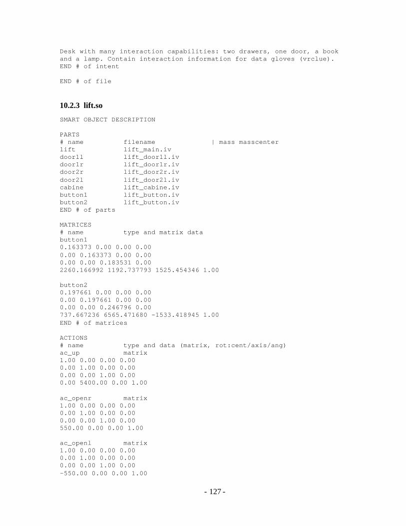
- 127 -
Desk with many interaction capabilities: two drawers, one door, a book and a lamp. Contain interaction information for data gloves (vrclue). END # of intent END # of file
10.2.3 lift.so
SMART OBJECT DESCRIPTION PARTS # name filename | mass masscenter lift lift_main.iv door1l lift_door1l.iv door1r lift_door1r.iv door2r lift_door2r.iv door2l lift_door2l.iv cabine lift_cabine.iv button1 lift_button.iv button2 lift_button.iv END # of parts MATRICES # name type and matrix data button1 0.163373 0.00 0.00 0.00 0.00 0.163373 0.00 0.00 0.00 0.00 0.183531 0.00 2260.166992 1192.737793 1525.454346 1.00 button2 0.197661 0.00 0.00 0.00 0.00 0.197661 0.00 0.00 0.00 0.00 0.246796 0.00 737.667236 6565.471680 -1533.418945 1.00 END # of matrices ACTIONS # name type and data (matrix, rot:cent/axis/ang) ac_up matrix 1.00 0.00 0.00 0.00 0.00 1.00 0.00 0.00 0.00 0.00 1.00 0.00 0.00 5400.00 0.00 1.00 ac_openr matrix 1.00 0.00 0.00 0.00 0.00 1.00 0.00 0.00 0.00 0.00 1.00 0.00 550.00 0.00 0.00 1.00 ac_openl matrix 1.00 0.00 0.00 0.00 0.00 1.00 0.00 0.00 0.00 0.00 1.00 0.00 -550.00 0.00 0.00 1.00

- 128 -
ac_press1 matrix 1.00 0.00 0.00 0.00 0.00 1.00 0.00 0.00 0.00 0.00 1.00 0.00 0.00 0.00 -50.00 1.00 ac_press2 matrix 1.00 0.00 0.00 0.00 0.00 1.00 0.00 0.00 0.00 0.00 1.00 0.00 0.00 0.00 50.00 1.00 END # of actions GESTURES # name filename actionfile part follow press ButtonPress ActionDefault button1 true false false 0.080000 0.311908 0.083569 -0.946429 0.00 -0.053292 0.996094 0.070391 0.00 0.948613 0.028482 0.315144 0.00 2192.496094 1231.207886 1716.597168 1.00 RightHandGeom: false press_2 ButtonPress ActionDefault button2 true false false 0.080000 -0.193824 -0.102024 0.975717 0.00 0.116514 0.985143 0.126156 0.00 -0.974093 0.138137 -0.179056 0.00 759.944946 6623.169434 -1735.859863 1.00 RightHandGeom: false END # of gestures POSITIONS # name position / orientation pos_press 1850.00 0.00 1935.00 0.347226 -0.001221 -0.937781 pos_enter 1290.00 0.00 2300.00 -0.050367 -0.003516 -0.998725 pos_enter 1800.00 0.00 2600.00 -0.151799 -0.003516 -0.988405 pos_goout 1290.00 0.00 2500.00 -0.050183 -0.001221 0.998739 pos_goout 1613.00 0.00 2000.00 -0.050183 -0.001221 0.998739 pos_goout 1290.00 0.00 1700.00 -0.050183 -0.001221 0.998739 pos_press_2 1100.00 5400.00 -2100.00 -0.250528 -0.054506 0.966574 pos_enter_2 1400.00 5400.00 -2300.00 0.050774 -0.001221 0.998709 pos_enter_2 1100.00 5400.00 -2581.00 0.050774 -0.001221 0.998709 pos_goout_2 1935.00 5400.00 -2600.00 0.050574 -0.024041 -0.998431 pos_goout_2 1613.00 5400.00 -2258.00 0.250901 -0.000185 -0.968013 pos_goout_2 1935.00 5400.00 -1835.00 0.050574 -0.024041 -0.998431 pos_cabine 1613.00 0.00 -550.00 0.151031 -0.000185 -0.988529 pos_cabine 1290.00 0.00 -123.00 0.151031 -0.000185 -0.988529 pos_cabine 1800.00 0.00 445.00 0.151031 -0.000185 -0.988529 pos_cabine_2 1613.00 5400.00 323.00 0.050774 -0.001221 0.998709 pos_cabine_2 1450.00 5400.00 -323.00 0.050774 -0.001221 0.998709 pos_cabine_2 1750.00 5400.00 -645.00 0.050774 -0.001221 0.998709 pos 0.00 0.00 0.00 0.00 0.00 0.00 END # OF POSITIONS COMMANDS

- 129 -
# name action part ini end inc cmd_cabto ac_up cabine 1.00 0.00 0.025000 cmd_cabto_2 ac_up cabine 0.00 1.00 0.025000 cmd_open ac_openr door1r 0.00 1.00 0.050000 cmd_open ac_openl door1l 0.00 1.00 0.050000 cmd_close ac_openr door1r 1.00 0.00 0.050000 cmd_close ac_openl door1l 1.00 0.00 0.050000 cmd_open_2 ac_openl door2r 0.00 1.00 0.050000 cmd_open_2 ac_openr door2l 0.00 1.00 0.050000 cmd_close_2 ac_openl door2r 1.00 0.00 0.050000 cmd_close_2 ac_openr door2l 1.00 0.00 0.050000 cmd_press ac_press1 button1 0.00 1.00 0.050000 cmd_press_2 ac_press2 button2 0.00 1.00 0.050000 cmd_unpress ac_press1 button1 1.00 0.00 0.050000 cmd_unpress_2 ac_press2 button2 1.00 0.00 0.050000 END # of commands VARIABLES open 0.00 open_2 0.00 floor 1.00 false 0.00 one 1.00 two 2.00 true 1.00 tmp 0.00 END # of variables # BEHAVIORS : BEHAVIOR open CheckVar open false SetVar open true DoCmd cmd_open END # of behavior BEHAVIOR open_2 CheckVar open_2 false SetVar open_2 true DoCmd cmd_open_2 END # of behavior BEHAVIOR close CheckVar open true SetVar open false DoCmd cmd_close END # of behavior BEHAVIOR close_2 CheckVar open_2 true SetVar open_2 false DoCmd cmd_close_2 END # of behavior BEHAVIOR press UserGoTo pos_press UserDoGest press RightHand DoCmd cmd_press

- 130 -
DoCmd cmd_unpress END # of behavior BEHAVIOR press_2 UserGoTo pos_press_2 UserDoGest press_2 RightHand DoCmd cmd_press_2 DoCmd cmd_unpress_2 END # of behavior BEHAVIOR moveto_2 CheckVar floor one SetVar floor two DoCmd cmd_cabto_2 END # of behavior BEHAVIOR moveto CheckVar floor two SetVar floor one DoCmd cmd_cabto END # of behavior BEHAVIOR move_cabine If floor one SetVar floor two DoCmd cmd_cabto_2 Else SetVar floor one DoCmd cmd_cabto EndIf END # of behavior BEHAVIOR enter_12 DoBh press DoBh moveto DoBh open UserGoTo pos_cabine DoBh close UserAttachTo cabine DoBh move_cabine UserDetach DoBh open_2 UserGoTo pos_goout_2 DoBh close_2 END # of behavior BEHAVIOR enter_21 DoBh press_2 DoBh moveto_2 DoBh open_2 UserGoTo pos_cabine_2 DoBh close_2 UserAttachTo cabine DoBh move_cabine UserDetach DoBh open UserGoTo pos_goout
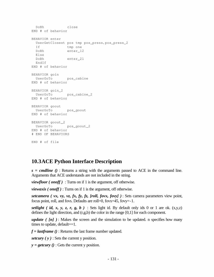
- 131 -
DoBh close END # of behavior BEHAVIOR enter UserGetClosest pos tmp pos_press,pos_press_2 If tmp one DoBh enter_12 Else DoBh enter_21 EndIf END # of behavior BEHAVIOR goin UserGoTo pos_cabine END # of behavior BEHAVIOR goin_2 UserGoTo pos_cabine_2 END # of behavior BEHAVIOR goout UserGoTo pos_goout END # of behavior BEHAVIOR goout_2 UserGoTo pos_goout_2 END # of behavior # END OF BEHAVIORS END # of file
10.3 ACE Python Interface Description
s = cmdline () : Returns a string with the arguments passed to ACE in the command line. Arguments that ACE understands are not included in the string.
viewfloor ( onoff ) : Turns on if 1 is the argument, off otherwise.
viewaxis ( onoff ) : Turns on if 1 is the argument, off otherwise.
setcamera ( vx, vy, vz, fx, fy, fz, [roll, fovx, fovy] ) : Sets camera parameters view point, focus point, roll, and fovs. Defaults are roll=0, fovx=45, fovy=-1.
setlight ( id, x, y, z, r, g, b ) : Sets light id. By default only ids 0 or 1 are ok. (x,y,z) defines the light direction, and (r,g,b) the color in the range [0,1] for each component.
update ( [n] ) : Makes the screen and the simulation to be updated. n specifies how many times to update, default==1.
f = lastframe () : Returns the last frame number updated.
setcury ( y ) : Sets the current y position.
y = getcury () : Gets the current y position.

- 132 -
loadfile ( filename ) : Loads an iv/wrl file and displays it.
avoidwalkcol ( onoff, [range, fov, gap, freq, sleep] ) : Turns on/off a simple collision avoidance during walk. Default is off, default parameters: range=1400, fov=10, gap=700, freq=3, sleep=5.
n = numvos () : Return the number of virtual objects. All ids created are inside the interval 0<=id.
vo = vonew ( name, filename, [px, pz, ox, oy, oz, color, d1, d2, d3] ) : Creates a virtual object solid or from a iv/wrl file at position (px,cury,pz) and orientation (ox,oy,oz). If filename == 'CUBE', (d1,d2,d3) = (length,height,width). If filename == 'CYLINDER', (d1,d2) = (radius,height). If filename == 'SPHERE', (d1) =(radius). String color can be: black, red, darkred, green, darkgreen blue, darkblue, yellow, darkyellow, magenta, darkmagenta cyan, darkcyan, gray, darkgray, white, skin.
vosetdata ( vo, data ) : Associates with vo any data for user usage.
data = vogetdata ( vo, [keep] ) : Retrieves the previously associated data. By default, keep==1, what means that the vobject keeps referencing the data. If keep==0, the data is dereferenced and thus destroyed automatically if the ref counter becomes 0.
bool = voisvh ( vo ) : Returns 1 if vo is the id of a virtual human, and false otherwise.
bool = voisso ( vo ) : Returns 1 if vo is the id of a smart object, and false otherwise.
vo = vofind ( name ) : Returns the id of the virtual object with the given name. -1 is returned if the name is not found.
name = voname ( vo ) : Returns the name of the virtual object vo.
vosetpos ( vo, x, z, [ox, oz, y, oy] ) : Puts vo in position (x,y,z) with orientation (ox,oy,oz) if y is not given, the current y is used.
voseeable ( vo, state ) : Sets vo to be perceivable or not from a vhuman. By default, all objects are seeable.
p = vogetpos ( vo ) : Gets the current position and orientation of vo. p is a list containing (x,z,ox,oz,y,oy). This order is to simplify most applications that work with 2d coordinates.
vodisplay ( vo, onoff ) : Will display or hide a vo.(not working...).
matrix = vogetlocalmat ( vo, [jointid] ) : Will get the matrix relative to the parent node. JointId can be specified for a vhuman and can be any of BODY_N3D* numbers in the file body_def.h.
vosetlocalmat ( vo, matrix, [jointid] ) : Will set the matrix relative to the parent node. JointId can be specified for a vhuman and can be any of BODY_N3D* numbers in the file body_def.h.
matrix = vogetglobalmat ( vo, [jointid] ) : Will get the matrix relative to the root scene node. JointId can be specified for a vhuman and can be any of BODY_N3D* numbers in the file body_def.h.

- 133 -
vr = vrusernew ( [onoff=1] ) : Creates a virtual hand connected to the fob and cyber glove. Only smart objects created before this command will be considered. If onoff is 0, FOB and Glove are not used.
vh = vhnew ( [name, inffile, px, pz, ox, oz] ) : Creates a new virtual human using the default virtual human path and the current y position. If inffile=="SOLID", a solid-type agent is created.
ok = vhstop ( vh, action_name, [face_decay] ) : Stops an action. action_name is a string containing the name of the saction. For example 'walk', 'look', etc. For actions that have a specific id, this id is to be used, like for 'keyframe'. 1 is returned if the action was found.
ok = vhactivate ( vh, action_name, [face_duration, face_weight, face_intensity] ) : Activates an action. action_name is a string containing the name of the saction. For example 'walk', 'look', etc. For actions that have a specific id, this id is be used, like for 'keyframe'. 1 is returned if the action was found.
vhbreathe ( vh, time, intensity ) : Changes the parameters of sa_breathe, default: 0.4, 1.5.
ok = vhtransitions ( vh, action_name, initial, final ) : Changes the transitions durations (in secs) of an action.
ok = vhloadface ( vh, face_name, filename ) : Loads a face expression file.
vhwalkspeed ( vh, lin, [ang] ) : Sets the linear and angular speed during walk. If a value is 0, it is not modified. By default, ang is 0.
vhwalk ( vh, px, pz, [ox, oz] ) : Makes the current virtual human to walk to the given location. The current y position is used.
bool = vhwalking ( vh ) : Returns 1 if the virtual human vh is walking, otherwise returns 0.
vhlook ( vh, x, z, [y] ) : Makes the virtual human to look to the given point. By default, y is equal to 1600.
vhloadkf ( vh, keyframe_name, trk_file ) : Load a keyframe and associate it to keyframe_name.
vhplay ( vh, keyframe_name ) : Play a previous loaded keyframe.
bool = vhplaying ( vh, keyframe_name ) : Returns 1 if the virtual human vh is playing the, keyframe with given name, otherwise returns 0.
l = vhperceive ( vh, [range, fov] ) : Returns list of perceived vo ids. By default, range and fov are -1, what makes the perception to work with the last value set for vh. Initially, the values are: range==10000mm, and fov==120 degrees.
sopath ( path ) : Changes the current path to search for smart objects.
so = sonew ( name, sofile, [px, pz, ox, oz] ) : Creates a new smart object. The default smart object path and the current y position are used.
sointeract ( so, vh, [bhname, bhindex] ) : Start interaction bhname. If a second integer argument indicating the index of the interaction is given, the index is used and the name is not considered.

- 134 -
bool = sointeracting ( so, [vh] ) : Returns 1 if the virtual human vh is interacting with the smart object so.
sowait ( so ) : Waits until all interactions are done.
soexec ( so, [bhindex, bhname] ) : Execute a smart object behavior with index bhindex. If bhindex is not given, the first interaction is used. To specify the interaction by a name, call with bhindex==-1 and bhname with the interaction name.
so = sogetcur () : Returns the last smart object that called a python callback.
n = sonumbhs ( so ) : Returns the number of available behaviors in the smart object.
s = sobhname ( so, bhid ) : Returns the name of the bhid behavior of the smart object.
n = sonumvars ( so ) : Return the number of state variables in the smart object.
s = sovarname ( so, varid ) : Returns the name of the varid state var of the smart object.
f = sogetvar ( so, varid, [varname] ) : Returns the state var value. If varid<0, varname is used.
souselook ( yes_or_no ) : Enable or not the use of sa_look during an object interaction.
10.4 ACE Example Python Scripts
The Python function extension used by ACE are defined as the module aglib, so that scripts must import this module. Some simple example Python scripts are shown here, the following one creates one actor, and inside a loop makes it walk in circles:
from math import * from aglib import * vh1 = vhnew("bob") radius = 2000 ang = 0 while ang<=6.4: if vhwalking(vh1)==0: ang = ang+0.5 vhwalk ( vh1, radius*sin(ang), radius*cos(ang) ) update()
The next script just creates 2 actors, an automatic door smart object, and commands the actors to interact with the door. Note that many default parameters are assumed, like when asking for the actor-object interaction, if no extra parameters are defined, the first available interaction of the smart object is used.

- 135 -
from aglib import * vh1 = vhnew ( "", "", 1000, 0 ) vh2 = vhnew ( "", "", 1200, 0 ) so1 = sonew ( "", "newso/autodoor.so" ) sointeract ( so1, vh1 ) sointeract ( so1, vh2 )
The next script loads an actor and a smart object computer and then calls a sequence of different actions and interactions, controlling a short animation sequence to take and put back the computer’s diskette.
from aglib import * setcamera ( 2578, 1354, 194, -2805, 497, 3242, 0, 45, -1 ) vh1 = vhnew ( "vh1" ) vo = sonew ( "computer", "test/computer.so" ) vosetpos ( vo, 1500, 1500, -1, 0 ); sointeract ( vo, vh1, "eject_floppy" ) sowait ( vo ) sointeract ( vo, vh1, "take_floppy" ) sowait ( vo ) vhwalk ( vh1, 0, 0 ) update ( 50 ) sointeract ( vo, vh1, "put_floppy" ) sowait ( vo ) sointeract ( vo, vh1, "push_floppy" ) sowait ( vo )
10.5 Actor Skeleton Joints
10.5.1 Skeleton Hierarchy
Figure 10.1 shows the skeleton joint hierarchy used to represent actors in BodyLib. For an explanation of the related libraries, see section 2.5.

- 136 -
Figure 10.1 – BodyLib skeleton Hierarchy.

- 137 -
10.5.2 Joints Used by Action Push
The following joints are animated by the implemented push action, using the inverse kinematics module, to perform actor-object manipulations. Note that some of the listed joint names exist both for right and left limbs, so that they’re used according if the manipulation is being done with the right or left hand.
VL1_TILT, VL2_TILT, VL2_ROLL, VL3_TILT, VL3_ROLL, VT4_TILT, VT4_ROLL, VT4_TORSION, VT5_ROLL, VT5_TORSION, CLAV_ABDUCT, CLAV_ROTATE, SHOULDER_FLEXION, SHOULDER_ABDUCT, SHOULDER_TWISTING, ELBOW_FLEXION, ELBOW_TWISTING, WRIST_FLEXION, WRIST_PIVOT.
The following joints are used only when the knee flexion configuration is used. Here, both the left and right joints relative to the following listed names are used. See section 5.4 for details.
HIP_FLEXION, KNEE_FLEXION, ANKLE_FLEXION.

- 138 -
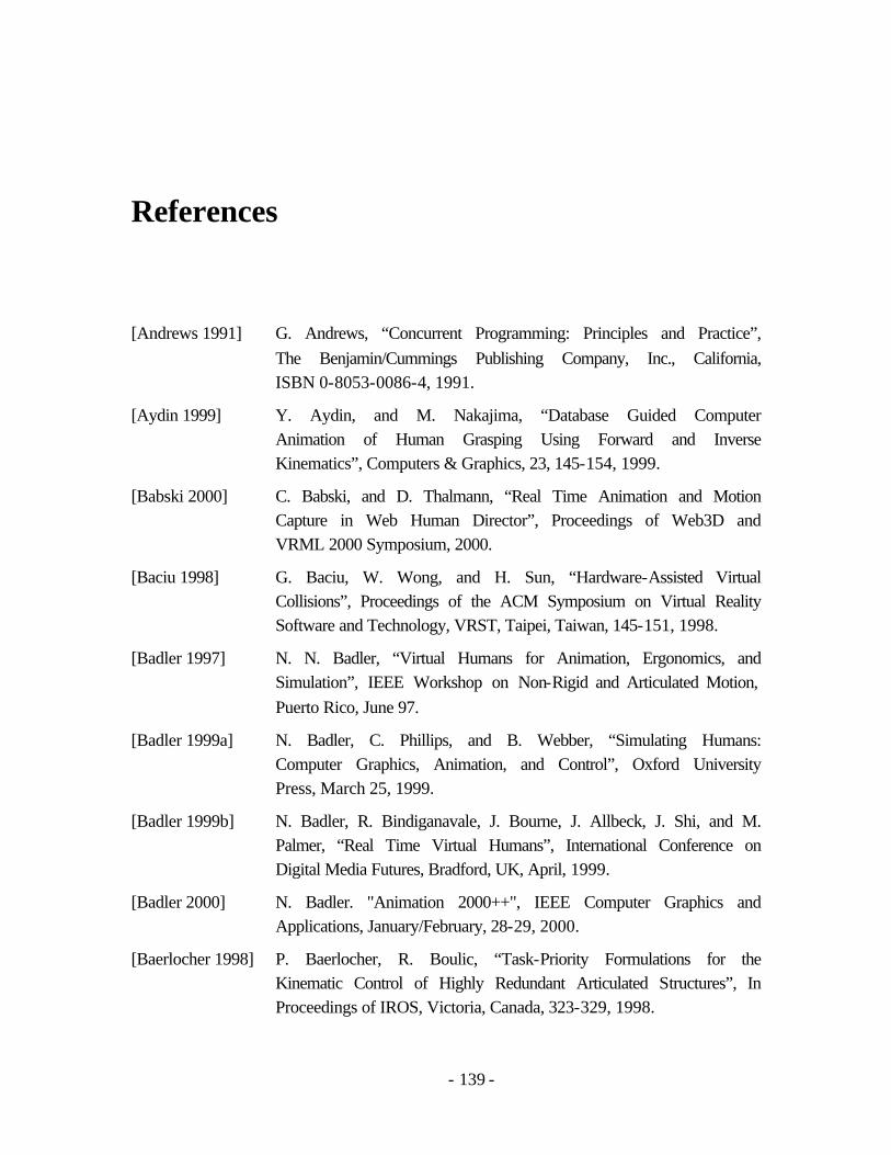
- 139 -
References
[Andrews 1991] G. Andrews, “Concurrent Programming: Principles and Practice”, The Benjamin/Cummings Publishing Company, Inc., California, ISBN 0-8053-0086-4, 1991.
[Aydin 1999] Y. Aydin, and M. Nakajima, “Database Guided Computer Animation of Human Grasping Using Forward and Inverse Kinematics”, Computers & Graphics, 23, 145-154, 1999.
[Babski 2000] C. Babski, and D. Thalmann, “Real Time Animation and Motion Capture in Web Human Director”, Proceedings of Web3D and VRML 2000 Symposium, 2000.
[Baciu 1998] G. Baciu, W. Wong, and H. Sun, “Hardware-Assisted Virtual Collisions”, Proceedings of the ACM Symposium on Virtual Reality Software and Technology, VRST, Taipei, Taiwan, 145-151, 1998.
[Badler 1997] N. N. Badler, “Virtual Humans for Animation, Ergonomics, and Simulation”, IEEE Workshop on Non-Rigid and Articulated Motion, Puerto Rico, June 97.
[Badler 1999a] N. Badler, C. Phillips, and B. Webber, “Simulating Humans: Computer Graphics, Animation, and Control”, Oxford University Press, March 25, 1999.
[Badler 1999b] N. Badler, R. Bindiganavale, J. Bourne, J. Allbeck, J. Shi, and M. Palmer, “Real Time Virtual Humans”, International Conference on Digital Media Futures, Bradford, UK, April, 1999.
[Badler 2000] N. Badler. "Animation 2000++", IEEE Computer Graphics and Applications, January/February, 28-29, 2000.
[Baerlocher 1998] P. Baerlocher, R. Boulic, “Task-Priority Formulations for the Kinematic Control of Highly Redundant Articulated Structures”, In Proceedings of IROS, Victoria, Canada, 323-329, 1998.

- 140 -
[Balcisoy 1998] S. Balcisoy, and D. Thalmann, “Hybrid Participant Embodiments in Networked Collaborative Virtual Environments”, In Proceedings of Multimedia Modeling’98, 130-137, IEEE, Lausanne, Switzerland, 1998.
[Balcisoy 2000] S. Balcisoy, M. Kallmann, P. Fua, and D. Thalmann, "A Framework for Rapid Evaluation of Prototypes with Augmented Reality", Proceedings of the ACM Symposium on Virtual Reality Software and Technology (VRST), 2000.
[Barwick 1993] S. Parry-Barwick, and A. Bowyer, “Is the Features Interface Ready?”, In “Directions in Geometric Computing”, Ed. Martin R., Information Geometers Ltd, UK, Cap. 4, 129-160, 1993.
[Battista 1999] G. Battista, P. Eades, R. Tamassia, and I. Tollis, “Graph Drawing – Algorithms for the Visualization of Graphs”, Prenticce Hall, ISBN 0-13-301615-3, 432pp, 1999.
[Baumgart 1972] B. G. Baumgart, “Winged−Edge Polyhedron Representation”, Technical Report STAN/CS/320, Stanford University, 1972.
[Becheiraz 1998] P. Becheiraz, “Un Modèle Comportemental et Émotionnel pour l’Animation d’Acteurs Virtuels”, PhD thesis, Swiss Federal Institute of Technology at Lausanne (EPFL), Lausanne, Switzerland, 1998.
[Berta 1999] J. Berta, “Integrating VR and CAD”, IEEE Computer Graphics and Applications, 14-19, September / October, 1999.
[Bindiganavale 1998] R. Bindiganavale, and N. Badler, “Motion Abstraction and Mapping with Spatial Constraints”, Proceedings of CAPTECH’98, Lecture Notes in Artificial Intelligence 1537, Springer, ISBN 3-540-65353-8, 70-82, 1998.
[Bindiganavale 2000] R. Bindiganavale, W. Schuler, J. Allbeck, N. Badler, A. Joshi, and M. Palmer, “Dynamically Altering Agent Behaviors Using Natural Language Instructions”, Proceedings of the 4th Autonomous Agents Conference, Barcelona, Spain, June, 293-300, 2000.
[Blumberg 1995] B. Blumberg, and T. Galyean, “Multi-Level Direction of Autonomous Creatures for Real-Time Virtual Environments”, Proceedings of SIGGRAPH’95 6(11), 47-54, Los Angeles, 1995.
[Booch 1991] G. Booch, “Object Oriented Design with Applications”, The Benjamin Cummings Publishing Company, Inc., ISBN 0-8053-0091-0, 1991.

- 141 -
[Bordeux 1999] C. Bordeux, R. Boulic, and D. Thalmann, “An Efficient and Flexible Perception Pipeline for Autonomous Agents”, Proceedings of Eurographics '99, Milano, Italy, 23-30, 1999.
[Boulic 1990] R. Boulic, N. Magnenat-Thalmann, and D. Thalmann, “A Global Human Walking Model with Real Time Kinematic Personification”, The Visual Computer, 6, 344-358, 1990.
[Boulic 1996] R. Boulic, S. Rezzonico, and D. Thalmann, “Multi Finger Manipulation of Virtual Objects”, Proceedings of the ACM Symposium on Virtual Reality Software and Technology, VRST, 67-74, 1996.
[Boulic 1997] R. Boulic, P. Bécheiraz, L. Emering, and D. Thalmann, “Integration of Motion Control Techniques for Virtual Human and Avatar Real-Time Animation”, In Proceedings of VRST’97, ACM press, 111-118, September 1997.
[Bowyer 1995] K. Bowyer, S. Cameron, G. Jared, R. Martin, A. Middleditch, M. Sabin, and J. Woodwark, “Introducing Djinn – A Geometric Interface for Solid Modelling”, Information Geometers, ISBN 1-874728-08-9, 24pp, 1995.
[Brisson 1989] E. Brisson, “Representing Geometric Structures in d-Dimensions: Topology and Order”, ACM Computational Geometry, 218-227, 1989.
[Brooks 1986] R. A. Brooks, “A Robust Layered Control System for a Mobile Robot”, IEEE Journal of Robotics and Automation, 2(1), 14-23, 1986.
[Burdea 1993] G. Burdea, and P. Coiffet, “Virtual Reality Technology”, Wiley Interscience, John Wiley & Sons, inc., ISBN 2-866601-386-7, 1993.
[Burdea 2000] G. Burdea, “Haptics Issues in Virtual Environments”, Proceedings of Computer Graphics International, 295-302, Geneva, Switzerland, June, 2000.
[Caicedo 1999] A. Caicedo, and D. Thalmann, “Intelligent Decision making for Virtual Humanoids”, Workshop of Artificial Life Integration in Virtual Environments, 5th European Conference on Artificial Life, Lausanne, Switzerland, September 1999, 13-17.

- 142 -
[Campagna 1999] S. Campagna, L. Kobbelt, and H. P. Seidel, “Directed Edges – A Scalable Representation for Triangle Meshes”, Journal of Graphics Tools 3, 4, 1-12, 1999.
[Carey 1997] R. Carey, and G. Bell, “The Annotated VRML 2.0 Reference Manual”, Addison Wesley, ISBN 0-201-41974-2, 1997.
[Cassel 1994] J. Cassel, C. Pelachaud, N. Badler, M. Steedman, B. Achorn, T. Becket, B. Douville, S. Prevost, and M. Stone, “Animated Conversation: Rule-Based Generation of Facial Expression, Gesture & Spoken Intonation for Multiple Conversational Agents”, Proceedings of SIGGRAPH’94, 413-420, 1994.
[Cassel 1999] J. Cassell, H. Vilhjálmsson, K. Chang, T. Bickmore, L. Campbell and H. Yan, “Requirements for an Architecture for Embodied Conversational Characters”, Eurographics Computer Animation and Simulation Workshop, 109-120, Springer Verlag, ISBN 3-211-83392-7, Vienna, Austria, 1999.
[Catia] Catia V5 Product from IBM. The Knowledgeware Technology. www-3.ibm.com/solutions/engineering/escatia.nsf/Public/know.
[Cavazza 1998] M. Cavazza, R. Earnshaw, N. Magnenat-Thalmann, and D. Thalmann, “Motion Control of Virtual Humans”, IEEE Computer Graphics & Applications, 18(5), 24-31, September/October, 1998.
[Cutkosky 1989] M. Cutkosky, “On Grasp Choice, Grasp Models, and the Design of Hands for Manufacturing Tasks”, IEEE Transactions on Robotics and Automation, 5(3), 269-279, 1989.
[Davis 1998] J. Davis, and A. Bobick “A Robust Human-Silhouette Extraction Technique for Interactive Virtual Environments”, Proceedings of the International Workshop on Modelling and Motion Capture Techniques for Virtual Environments, CAPTECH ‘98, 12-25, ISBN 3-540-65353-8, Geneva, Switzerland, 1998.
[Delingette 1994] H. Delingete, “Simplex Meshes: A General Representation for 3D Shape Reconstruction”, Proceedings of the International Conference on Computer Vision and Pattern Recognition, CVPR'94, Seattle, USA, June, 1994.
[Dinsmore 1995] M. Dinsmore, N. Langrana, G. Burdea, and J. Ladeji, “Virtual Reality Training Simulation for Palpation of Subsurface Tumors”, Proceedings of the Virtual Reality Annual International Symposium, VRAIS’95, March 1-5, Albuquerque, New Mexico, 54-60, 1995.

- 143 -
[Donikian 1994] S. Donikian, and B. Arnaldi, “Complexity and Concurrency for Behavioral Animation and Simulation”, Eurographics Computer Animation and Simulation Workshop, Oslo, Norvege, September, 1994.
[Donnart 1996] J. Y. Donnart, and J. A. Meyer, “Learning Reactive and Planning Rules in a Motivationally Autonomous Animat”. IEEE Transactions on Systems, Man, and Cybernetics, part B: Cybernetics, 26(3), 381-395, June, 1996.
[Emering 1999] L. Emering, “Human Action Modeling and Recognition for Virtual Environments”, PhD Thesis, Swiss Federal Institute of Technology - EPFL, Lausanne, Switzerland, 1999.
[Farenc 2000] N. Farenc, S. R. Musse, E. Schweiss, M. Kallmann, O. Aune, R. Boulic, and D. Thalmann, “A Paradigm for Controlling Virtual Humans in Urban Environment Simulations”, Applied Artificial Intelligence Journal 14(1), ISSN 0883-9514, January, 69-91, 2000.
[Farin 1992] G. Farin, “Curves and Surfaces for Computer Aided Geometric Design: a Practical Guide”, 3rd edition, Academic Press, London, ISBN 0-12-249052-5, 1992.
[FLTK] FLTK web address: www.fltk.org.
[Foley 1992] J. D. Foley, A. van Dam, S. K. Feiner, and J. F. Jughes, “Computer Graphics: Principles and Practice”, 2nd edition, Reading MA: Addision/Wesley, 1992.
[Foley 2000] J. D. Foley, “Getting There: The Ten Top Problems Left”, IEEE Computer Graphics and Applications, January/February, 66-68, 2000.
[Franklin 1996] S. Franklin, and A. Graesser, “Is it an Agent, or Just a Program?: a Taxonomy for Autonomous Agents”, Proceedings of the Third International Workshop on Agent Theories, Architectures, and Languages, Springler Verlag, Berlin/Heidelberg, Germany, 1996.
[Funge 1999] J. Funge, “AI for Games and Animation: A Cognitive Modeling Aproach”, A. K. Peters, Natick, MA, 1999.
[Geib 1994a] C. Geib, L. Levison, and M. Moore, “SodaJack: An Architecture for Agents that Search for and Manipulate Objects”, Technical Report MS-CIS-94-13, University of Pennsylvania, 1994.

- 144 -
[Geib 1994b] C. Geib, “The Intentional Planning System: ItPlanS”, Proceedings of AIPS, 1994.
[Gibson 1977] J. J. Gibson, “The theory of affordances”, In R. Shaw & J. Brandsford (eds.), Perceiving, Acting and Knowing. Hillsdale, NJ:Erlbaum, 1977.
[Granieri 1995] J. Granieri, W. Becket, B. Reich, J. Crabtree, and N. Badler, “Behavioral Control for Real-Time Simulated Human Agents”, Symposium on Interactive 3D Graphics, 173-180, 1995.
[Guibas 1985] L. Guibas and J. Stolfi, “Primitives for the Manipulation of General Subdivisions and the Computation of Voronoi Diagrams”, ACM Transaction on Graphics, 4, 75-123, 1985.
[Hand 1997] C. Hand, “A Survey of 3D Interaction Techniques”, Computer Graphics Forum, 16(5), 269-281, 1997.
[Hettinger 1997] L. Hettinger, “Perceiving in Virtual Environments: The Multisensory Nature of Real and Virtual Worlds”, Tutorial Notes, Proceedings of the ACM Symposium on Virtual Reality Software and Technology (VRST), September, Lausanne, Switzerland, 1997.
[Hodgins 1995] J. Hodgins, W. Wooten, D. Brogan, and J. O'Brien, “Animating Human Athletics”, In Proceedings of SIGGRAPH '95, 6(11), 71-78, Los Angeles, 1995.
[Huang 1995] Z. Huang, R. Boulic, N. Magnenat-Thalmann, and D. Thalmann, “A Multi-Sensor Approach for Grasping and 3D Interaction”, Proceedings of Computer Graphics International, Leeds, UK, June, 1995.
[Johnson 1997] W. Johnson, and J. Rickel, “Steve: An Animated Pedagogical Agent for Procedural Training in Virtual Environments”, SIGART Bulletin, ACM Press, 8(1-4), 16-21, 1997.
[Kalawsky 1993] R. S. Kalawsky, “The Science of Virtual Reality and Virtual Environments”, Addison-Wesley, ISBN 0-201-63171-7, 1993.
[Kallmann 1998] M. Kallmann and D. Thalmann, “Modeling Objects for Interaction Tasks”, EGCAS’98 - 9th Eurographics Workshop on Animation and Simulation, 73-86, Lisbon, Portugal, 1998.
[Kallmann 1999a] M. Kallmann and D. Thalmann, “A Behavioral Interface to Simulate Agent-Object Interactions in Real-Time”, Proceedings of Computer Animation 99, IEEE, 138-146, Geneva, 1999.

- 145 -
[Kallmann 1999b] M. Kallmann, D. Thalmann, “Direct 3D Interaction with Smart Objects”, Proceedings of ACM VRST'99, London, December, 1999.
[Kallmann 2000a] M. Kallmann, J. Monzani, A. Caicedo, and D. Thalmann, “ACE: A Platform for the Real Time Simulation of Virtual Human Agents”, EGCAS’2000 - 11th Eurographics Workshop on Animation and Simulation, Interlaken, Switzerland, 2000.
[Kallmann 2000b] M. Kallmann, E. de Sevin, and D. Thalmann, “Constructing Virtual Human Life Simulations”, Proceedings of the Avatars’2000 workshop, Lausanne, Switzerland, 2000.
[Kalra 1992] P. Kalra, A. Mangeli, N. Magnenat Thalmann, and D. Thalmann, “Simulation of Facial Muscle Actions Based on Rational Free Form Deformations”, Proceedings of Eurographics’92, 59-69, 1992.
[Kalra 1998] P. Kalra, N. Magnenat Thalmann, L. Moccozet, G. Sannier, A. Aubel, and D. Thalmann, “Real-Time Animation of Realistic Virtual Humans”, IEEE Computer Graphics & Applications, 18(5), 42-56, September/October, 1998.
[Kettner 1998] L. Kettner, “Designing a Data Structure for Polyhedral Surfaces”, Proceedings of the Fourteenth Annual Symposium on Computational Geometry, Minneapolis, Minnesota, USA, 146-154, June, 1998.
[Kitamura 1998] Y. Kitamura, A. Yee, and F. Kishino, “A Sophisticated Manipulation Aid in a Virtual Environment using Dynamic Constraints among Object Faces”, Presence, 7(5), 460-477, October, 1998.
[Koga 1994] Y. Koga, K. Kondo, J. Kuffner, and J. Latombe, “Planning Motions with Intentions”, Proceedings of SIGGRAPH’94, 395-408, 1994.
[Latombe 1991] J.-C. Latombe, “Robot Motion Planning”, ISBN 0-7923-9206-X, Kluwer Academic Publishers, Boston, 1991.
[Levinson 1994a] L. Levinson and N. Badler, “How Animated Agents Perform Tasks: Connecting Planning and Manipulation Throught Object-Specific Reasoning”, In Working Notes from the Workshop on “Towards Physical Interaction and Manipulation”, AAAI Spring Symposium, 1994.
[Levinson 1994b] L. Levinson, “Connecting Planning and Acting: Towards an Architecture for Object-Specific Reasoning”, PhD thesis, University of Pennsylvania, 1996.

- 146 -
[Lienhardt 1989] P. Lienhardt, “Subdivisions of N-Dimensional spaces and N-Dimensional Generalized Maps”, ACM Symposium on Computational Geometry, 228-236, 1989.
[Luckas 1997] V. Luckas, and T. Broll, “CASUS, An Object-Oriented Three-Dimensional Animation System for Event-Oriented Simulators”, Proceedings of Computer Animation, IEEE, 144-150, Geneva, 1997.
[Lutz 1996] M. Lutz, “Programming Python”, Sebastapol: O’Reilly, 1996. (see also: www.python.org)
[Maes 1995] P. Maes, T. Darrell, B. Blumberg, and A. Pentland, “The ALIVE System: Full-body Interaction with Autonomous Agents”, In Proceedings of Computer Animation, IEEE, 11-18, Geneva, Switzerland, 1995.
[Mäntylä 1988] M. Mäntylä, “An Introduction to Solid Modeling”, Computer Science Press, Maryland, ISBN 0-88175-108-1, 1988.
[Microsoft] Microsoft Corporation web page, www.microsoft.com.
[Millar 1999] R. J. Millar, J. R. P. Hanna, and S. M. Kealy, “A Review of Behavioural Animation”, Computer & Graphics, 23, 127-143, 1999.
[Mine 1995] M. Mine, “Virtual Environment Interaction Techniques”, UNC Chapel Hill, Computer Science, Technical Report TR95-018, 1995.
[Mine 1997] M. Mine, F. P. Brooks Jr., and C. Sequin, “Moving Objects in Space Exploiting Proprioception in Virtual Environment interaction”, Proceedings of SIGGRAPH’97, Los Angeles, CA, 1997.
[Moccozet 1997] L. Moccozet, and N. Magnenat-Thalmann, “Dirichlet Free-Form Deformations and their Application to Hand Simulation”, in Proceedings of Computer Animation, IEEE, 93-102, Geneva, 1997.
[Molet 1996] T. Molet, R. Boulic, and D. Thalmann, “A Real-Time Anatomical Converter for Human Motion Capture”, in Proceedings of Eurographics Workshop on Computer Animation and Simulation, 79-94, Springer, Wien, 1996.
[Molet 1998] T. Molet, “Etude de la Capture de Mouvements Humains pour l’Interaction en Environnements Virtuels”, PhD thesis, Swiss Federal Institute of Technology at Lausanne (EPFL), Lausanne, Switzerland, 1998.

- 147 -
[Monzani 2000] J. Monzani and D. Thalmann, “A Sound Propagation Model for Interagents Communication”, Procedings of the 2nd Virtual Worlds Conference – VW2000, 135-146, Paris, France, 2000.
[Moreau 1998] G. Moreau, and S. Donikian, “From Psychological and Real-Time Interaction Requirements to Behavioural Simulation”, EGCAS’98 - 9th Eurographics Workshop on Animation and Simulation, Lisbon, Portugal, 29-44, 1998.
[Motion Star] Ascension web address: www.ascension-tech.com.
[Motivate] Motivate product information, Motion Factory web address: www.motion-factory.com.
[Musse 1997] S. Musse, and D. Thalmann, “A Model of Human Crowd Behavior: Group Inter-Relationship and Collision Detection Analysis”, In Proceedings of the Eurographics Workshop on Computer Animation and Simulation, 39-51, Budapest, Hungary, September, 1997.
[Nemo] Nemo game engine web page: www.nemo.com.
[Newel 1982] A. Newell, “The knowledge level”, Artificial Intelligence, 18, 87-127, 1982.
[Nishino 1997] H. Nishino, K. Utsumiya, D. Kuraoka and K. Korida, “Interactive Two-Handed Gesture Interface in 3D Virtual Environments”, Proceedings of the ACM Symposium on Virtual Reality Software and Technology, VRST, Lausanne, Switzerland, 1-14, 1997.
[Norvig 1992] P. Norvig, “Paradigms of Artificial Intelligence Programming: Case Studies in Common Lisp”, M. Kaufmann, ISBN 1-55860-191-0, 1992.
[Noser 1996] H. Noser, “A Behavioral Animation System based on L-Systems and Synthetic Sensors for Actors”, PhD thesis, Swiss Federal Institute of Technology at Lausanne (EPFL), Lausanne, Switzerland, 1996.
[Okada 1999] Y. Okada, K. Shinpo, Y. Tanaka and D. Thalmann, “Virtual Input Devices based on Motion Capture and Collision Detection”, Proceedings of Computer Animation 99, Geneva, May, 1999.
[Paoluzzi 1995] A. Paoluzzi, V. Pascucci, and M. Vicentino, “Geometric Programming: A Programming Approach to Geometric Design”, ACM Transactions on Graphics, 14(3), 266-306, July, 1995.

- 148 -
[Pentland 1995] A. Pentland, “Machine Understanding of Human Action”, 7th International Forum on Frontier of Telecom Technology, Tokyo, Japan, 1995.
[Perlin 1996] Perlin K., and A. Goldberg, “Improv: A System for Scripting Interactive Actors in Virtual Worlds”, In Proceedings of SIGGRAPH’96, 205-216, 1996.
[Popescu 1999] V. Popescu, G. Burdea, and M. Bouzit, “VR Simulation Modelling for a Haptic Glove”, Proceedings of Computer Animation 99, Geneva, May, 1999.
[Poupyrev 1997] I. Poupyrev, S. Weghorst, M. Billinghurst, and T. Ichikawa, “A Framework and Testbed for Studying Manipulation Techniques for Immersive VR”, Proceedings of the ACM Symposium on Virtual Reality Software and Technology, VRST, Lausanne, Switzerland, 21-28, 1997.
[Pratt 1985] M. J. Pratt, and P. R. Wilson, “Requirements for Support of Form Features in a Solid Modeling System”, Report R-85-ASPP-01, CAM-I, 1985.
[Renault 1990] O. Renault, N. Magnenat-Thalmann, and D. Thalmann, “A Vision-based Approach to Behavioral Animation”, The Journal of Visualization and Computer Animation, 1(1), 18 – 21, 1990.
[Reynolds 1987] C. Reynolds, “Flocks, Herds and Schools: A Distributed Behavioral Model”, Proceedings of SIGGRAPH ’87, Computer Graphics, v.21, n.4, July, 25-34, 1987.
[Reynolds 1999] C. Reynolds, “Steering Behaviours for Autonomous Characters”, Game Developers Conference, 1999.
[Russel 1995] K. Russell, T. Starner, and A. Pentland, “Unencumbered Virtual Environments”, International Joint Conference on Artificial Intelligence Entertainment and AI, ALife Workshop, 1995.
[Sannier 1999] G. Sannier, S. Balcisoy, N. Magnenat-Thalmann, and D. Thalmann, “VHD: System for Directing Real-Time Virtual Actors”, The Visual Computer, Springer, 15(7/8), 320-329, 1999.
[Sauer 1998] J. Sauer and E. Schömer, “A Constraint-Based Approach to Rigid Body Dynamics for Virtual Reality Applications”, Proceedings of the ACM Symposium on Virtual Reality Software and Technology, VRST, Taipei, Taiwan, 153-161, 1998.
- 149 -
[Sevin 2001] E. de Sevin, M. Kallmann and D. Thalmann, “Towards Real Time Virtual Human Life Simulations”, Submitted to Computer Graphics International Symposium 2001.
[Simeon 2000] T. Simeon, J. P. Laumond, and C. Nissoux, “Visibility Based Probabilistic Roadmaps for Motion Planning”, Advanced Robotics Journal 14(2), 2000.
[Schoeler 2000] A. Schoeler, R. Angros, J. Rickel, and W. Johnson, “Teaching Animated Agents in Virtual Worlds”, Smart Graphics, Stanford, CA, USA, 20-22, March, 2000.
[SGI] Silicon Graphics Inc. web page, www.sgi.com.
[Shah 1995] J. J. Shah, and M. Mäntylä, “Parametric and Feature-Based CAD/CAM”, John Wiley & Sons inc. ISBN 0-471-00214-3, 1995.
[Stanney 1998] K. M. Stanney, R. R. Mourant, and R. S. Kennedy, “Human Factors Issues in Virtual Environments: A Review of the Literature”, Presence, 7(4), 327-351, August, 1998.
[Stanney 1998] K. Stanney, R. Mourant, and R. Kennedy, “Human Factors Issues in Virtual Environments: A Review of the Literature”, Presence 7(4), 327-351, August, 1998.
[Stereographics] Stereo Graphics web address: www.stereographics.com
[Strassmann 1991] S. H. Strassmann, “Desktop Theater: Automatic Generation of Expressive Animation”, PhD thesis, Massachusetts Institute of Technology (MIT), School of Architecture and Planning, Media Arts and Sciences Section, June, 1991.
[Sturman 1994] D. Sturman, and D. Zeltzer, “A Survey of Glove-based Input”, IEEE Computer Graphics and Applications, 30-39, January, 1994.
[Tate 1995] D. Tate and L. Sibert, “Virtual Environments for Shipboard Firefighting Training”, Proceedings of the Virtual Reality Annual International Symposium, VRAIS’95, March 1-5, Albuquerque, New Mexico, 61-68, 1995.
[TGS] Template Graphics Software Inc. web page, www.tgs.com.
[Thalmann 1990] N. Magnenat Thalmann and D. Thalmann, “Computer Animation: Theory and Practice”, 2nd edition, Springer-Verlag Tokyo, ISBN 0-387-70051-X, 1990.

- 150 -
[Thalmann 1991] N. Magnenat Thalmann and D. Thalmann, “New Trends in Animation and Visualization”, John Wiley & Sons Ltd., England, ISBN 0-471-93020-2, 1991.
[Thalmann 1993] N. Magnenat Thalmann and D. Thalmann, “Models and Techniques in Computer Animation”, Springer-Verlag, Tokyo, ISBN 0-387-70124-9, 1993.
[Thalmann 1996] D. Thalmann, J. Shen, and E. Chauvineau, “Fast Human Body Deformations for Animation and VR Applications”, Proceedings of the Computer Graphics International, CGI’96, 166-174, June, 1996.
[TheSims] “The Sims” game web address: www.thesims.com/us.
[Tolani 1996] D. Tolani, and N. Badler, “Real-Time Inverse Kinematics of the Human Arm”, Presence 5(4), 393-401, 1996.
[Tsutsuguchi 2000] K. Tsutsuguchi, S. Shimada, Y. Suenaga, N. Sonehara, and S. Ohtsuka, “Human Walking Animation Based on Foot Reaction Force in the Three-Dimensional Virtual World”, The Journal of Visualization and Computer Animation, 2(1), February, 3-16, 2000.
[Tu 1994] X. Tu, and D. Terzopoulos, “Artificial Fishes: Physics, Locomotion, Perception, Behaviour”, Proceedings of Computer Graphics, 43-50, 1994.
[Tyrrel 1993] T. Tyrrel, “Defining the Action Selection Problem”, Proceedings of the Fourteen Annual Conference on Cognitive Science Society”, Lawrence Erlbaum Associates, 1993.
[Vince 1992] J. Vince, “3-D Computer Animation”, Addison-Wesley, ISBN 0-201-62756-6, 1992.
[VirTech] Virtual Technologies web address: www.virtex.com.
[VRML] VRML web address: www.vrml.org.
[Wang 1998] X. Wang, and J. Verriest, “A Geometric Algorithm to Predict the Arm Reach Posture for Computer-aided Ergonomic Evaluation”, The Journal of Visualization and Computer Animation, 9, 33-47, 1998.
[Watt 1989] A. Watt, “Fundamentals of Three-Dimensional Computer Graphics”, Wokingham: Addison-Wesley, 1989.
[Watt 1992] A. Watt and M. Watt, “Advanced Animation and Rendering Techniques”, Wokingham: Addison-Wesley, 1992.

- 151 -
[Webber 1995] B. Webber, N. N. Badler, B. Di Eugenio, C. Geib, L. Levison, and M. Moore, “Instructions, Intentions and Expectations”, Artificial Intelligence Journal, 73, 253-269, 1995.
[Weiler 1985] K. Weiler, “Edge based Data Structures for Solid Modeling in Curved-Surface Environments”, IEEE Computer Graphics and Applications, 5(1):21-40, January 1985.
[Wernecke 1994] J. Wernecke, “The Inventor Mentor: Programming Object-Oriented 3D Graphics with Open Inventor Rel. 2”, Addison-Wesley, ISBN 0-201-62495-8, 1994.
[Wiley 1997] D. Wiley, and J. Hahn, “Interpolation Synthesis for Articulated Figure Motion”, Virtual Reality Annual International Symposium, Albuquerque, New Mexico, March, 1997.
[Wooldridge 1995] M. Wooldridge, and N. R. Jennings, “Intelligent Agents: Theory and Practice”, Knowledge Engineering Review, 10(2), June, 1995.
[Zeltzer 1991] D. Zeltzer, “Task-level Graphical Simulation: Abstraction, Representation and Control”, Making them Move: Mechanics, Control and Animation of Articulated Figures, N. Badler, B. Barsky and D. Zeltzer eds., 3-33, 1991.
[Ziemke 1998] T. Ziemke, “Adaptive Behavior in Autonomous Agents”, Presence, vol. 7, no. 6, 564-587, december 1998.
[Zorin 2000] D. Zorin, and P. Schröder, “Subdivision for Modeling and Animation”, SIGGRAPH course notes, 2000.

- 152 -

- 153 -
Curriculum Vitae
Marcelo Kallmann is currently a PhD candidate at the Computer Graphics Lab of the Swiss Federal Institute of Technology in Lausanne (EPFL) since 1997. He obtained his diploma on mathematics from the State University of Rio de Janeiro (UERJ) in 1993, and after following some courses at the Institute for Pure and Applied Mathematics (IMPA), he did his MSc thesis on the subject of polyhedral morphing at the Computer Graphics Lab of the Federal
University of Rio de Janeiro (COPPE/UFRJ), Brazil. His research interests range from Computational Geometry, Robotics and Data Structures to Behavioral Animation, Modeling and Virtual Reality. His web address is ligwww.epfl.ch/kallmann.html.
Publications
E. de Sevin, M. Kallmann, and Daniel Thalmann, “Towards Real Time Virtual Human Life Simulations”, Computer Graphics International (CGI), 2001 (to appear).
S. Balcisoy, M. Kallmann, R. Torre, P. Fua, and D. Thalmann, “Interaction Techniques with Virtual Humans in Mixed Environments”, Proceedings of the Second International Symposium on Mixed Reality, Yokohama, Japan, 2000.
M. Kallmann, E. de Sevin, and D. Thalmann, “Constructing Virtual Human Life Simulations”, Avatars’2000 Workshop, EPFL, Lausanne, Switzerland, 2000.
S. Balcisoy, M. Kallmann, P. Fua, and D. Thalmann, “A Framework for Rapid Evaluation of Prototypes with Augmented Reality”, Proceedings of ACM VRST, 2000.
M. Kallmann, J.-S. Monzani, A. Caicedo, and D. Thalmann, “ACE: A Platform for the Real Time Simulation of Virtual Human Agents”, EGCAS’2000 - Eurographics Workshop on Computer Animation and Simulation, Interlaken, 2000.
M. Kallmann, J.-S. Monzani, A. Caicedo, and D. Thalmann, “A Common Environment for Simulating Virtual Human Agents in Real Time”, Workshop on Achieving Human-Like Behavior in Interactive Animated Agents, Spain, 2000.

- 154 -
N. Farenc, S. Musse, E. Schweiss, M. Kallmann, O. Aune, R. Boulic, and D. Thalmann, “A Paradigm for Controlling Virtual Humans in Urban Environment Simulations”, Applied Artificial Intelligence Journal 14(1), 69-91, 2000.
D. Thalmann, S. R. Musse, M. Kallmann, “From Individual Human Agents to Crowds”, Informatik / Informatique, Number 1, 2000.
M. Kallmann, D. Thalmann, “Direct 3D Interaction with Smart Objects”, Proceedings of ACM VRST'99, December, London, 1999.
S. R. Musse, M. Kallmann and D.Thalmann, “Levels of Autonomy for Virtual Human Agents”, Proceedings of the European Conference on Artificial Life, ECAL'99 poster, Lausanne, Switzerland, 345-349, 1999.
M. Kallmann and D. Thalmann, “A Behavioral Interface to Simulate Agent-Object Interactions in Real-Time”, Proc. of Computer Animation, IEEE, 138-146, Geneva, 1999.
D. Thalmann, S. R. Musse and M. Kallmann, “Virtual Humans' Behavior: Individuals, Groups, and Crowds”, Digital Media Futures, Bradford, UK, 1999.
M. Kallmann and D. Thalmann, “Modeling Objects for Interaction Tasks”, 9th Eurographics Workshop on Animation and Simulation, 73-86, Lisbon, Portugal, 1998.
N. Farenc, S. R. Musse, E. Schweiss, M. Kallmann, O. Aune, R. Boulic, and D. Thalmann, “One Step Towards Virtual Human Management for Urban Environments Simulation”, ECAI'98 - Workshop of Intelligent Virtual Environments, 1998.
M. Kallmann and A. Oliveira, “Homeomorphisms and Metamorphosis of Polyhedral Models Using Fields of Directions Defined on Triangulations”, Journal of the Brazilian Computer Society, ISSN 0104-6500 vol. 3 num. 3, April, 52-64, 1997.
M. Kallmann and A. Oliveira, “Metamorphosis of Polyhedral Models Using Fields of Directions in Tetrahedralizations”, Proceedings of the Brazilian Symposium of Computer Graphics and Image Processing – SIBGRAPI, 1996. In Portuguese.
M. Kallmann, “Representing Spatial Subdivisions and applying the Delaunay Triangulation”. Proceedings of the Brazilian Symposium of Computer Graphics and Image Processing – SIBGRAPI, 1995. In Portuguese.
M. Kallmann, “A Structure to Represent Spatial Subdivisions and the Delaunay Triangulation”, Tech. Report ES-365/96 – COPPE/UFRJ. In Portuguese.
A. Oliveira, M. Kallmann, J. Pio, L. Garcia and R. Farias, “Introductory Papers for Problems of the kind Shape from X”, Tech. Report ES-364/95, COPPE/UFRJ. In Portuguese.