O&M Manual - Boyle Construction
13
O&M Manual Client: McGonagle Group Site: Letterkenny General Hospital, New Medical Academy Scope of works: Supply & Deliver: 1-no 10,000Ltr Bunded Rectangular Steel Tank 1-no TMS Electronic Tank Gauges Index: 1. Tank Drawing 2. Tank Pressure Test Certificate 3. TMS Gauge Sales Literature 4. TMS Tank Gauge Commissioning Certificate 5. TMS Gauge Technical Data Sheets 6. TMS Gauge Wiring Diagram 7. TMS Gauge Certificate of Conformance
Transcript of O&M Manual - Boyle Construction

O&M Manual
Client: McGonagle Group Site: Letterkenny General Hospital, New Medical Academy Scope of works: Supply & Deliver:
1-no 10,000Ltr Bunded Rectangular Steel Tank 1-no TMS Electronic Tank Gauges
Index:
1. Tank Drawing 2. Tank Pressure Test Certificate 3. TMS Gauge Sales Literature 4. TMS Tank Gauge Commissioning Certificate
5. TMS Gauge Technical Data Sheets 6. TMS Gauge Wiring Diagram 7. TMS Gauge Certificate of Conformance

Jonathan.Heasley
Typewriter
1800KGS
Jonathan.Heasley
Typewriter
McGonagle Group Letterkenny Hospital
Jonathan.Heasley
Typewriter
Jonathan.Heasley
Typewriter
Tank for New Medical Academy
Jonathan.Heasley
Typewriter
Jonathan.Heasley
Typewriter
1480
Jonathan.Heasley
Typewriter

Test Certificate 120900
Tank 10000BN
Capacity Litres 10,000
A B C D E F
Overall Tank Inner Tank Nominal
Length Height Length Capacity
4000 2000 3570 10,000Lt
Inner Tank Outer Tank Test Test
Thickness Thickness Pressure Date
4mm 4mm 0.7BAR June-15
G H K Customers Name & Address
Tank No. Certificate Authorised
Number By
1480 120900 J.H.
Note: All material is measured in mm.
All Pressures are measured in Bar.
All Capacities are measured in Litres.
Donegal
Overground Rectangular Bunded Steel Fuel Storage Tank
McGonagle Group
New Medical Academy
Letterkenny General Hospital

Tank level monitoringmade easy…The Tank Monitoring System is a bespoke design to control, monitor and accommodate the efficient storage and dispensing of diesel, chemicals, adblue and bio-fuels.
• The TMS and GSM telemetry unit is installed at the tank.
• Tank stocks sent via GSM telemetry to our central database at a customer specified time which automatically processes the data for each tank.
• Tank level data can be viewed via your web browser - www.connectsensor.com (operational May 09).
How it works
Advantages• Improved delivery schedules and efficient route planning.
• Optimised inventory management.
• Customer binding.
• Improved security.
• Saves fitting time.
• Elimates the need for manual measurements.
• Receive timely and accurate data for competitive product purchases.
• Avoid downtime from running out of product.
• Cost effective solutions.
Features• Fast and easy installation.
• No fixed phone line required.
• 230VAC supply required to TMS.
• Robust design for outdoor and indoor installation - IP65 rated enclosure.
• Access through www.connectsensor.com (operational May 09).
• Web based search and filter functions to view specific data. (operational May 09).
• Online graphical presentation of historical data by week, month and year (operational May 09).
• Can be linked to Building Management System.
• Integral high low level alarm.
• Dispensed quantity.
• High resolution.

TMS Options TMS 100 TMS 200Litre Readout Yes Yes
Overfill Alarm Yes Yes
Bund Alarm Yes Yes
Low Level Indication Yes Yes
Pressure Sensor 4-20mA Optional Optional
Ultrasonic Sensor Yes Optional
GSM Module Optional Optional
Pulse Meter Compatibility No Yes
Fan Control No Yes
Tank Heater Control No Yes
Fieldgate connection No Yes
4-20mA Output for BMS No Yes
3-no 10A Relays for External Equipment No Yes
External Light Control No Yes
GOK Power Connection No Yes
TMS Options
Kingspan Environmental LtdSensor Systems Team
180 Gilford Road, Portadown, Co. ArmaghNorthern Ireland BT63 5LF.
Sales Hotline: +44 (0) 28 3836 4411 Fax: +44 (0) 28 3836 4412
Email: [email protected] Web: www.sensor-systems.com or www.connectsensor.com
or visit our company website: www.kingspanenv.com
Further OptionsOnline monitoring via www.connectsensor.com (available May 09)
• Security alarm option• Heating and lighting control
Above shows graphicalillustration of consumption over time.
Information displayed in user defined fields.

Tank Gauge Commissioning Certificate
Customer: McGonagle Group
Tank: 10000BN Tank No: 1471
Site Name: Letterkenny General Hospital, New Medical Academy Site Address: Letterkenny, Co Donegal
Tank manufacturer: Kingspan Environmental Ltd
Tank Nominal Capacity: 10,000 Litres Brimful Capacity: 10,200 Litres
High Level Alarm: 10,000 Litres Low Level Alarm: 1,000 Litres
Product to be Stored: Marked Gas Oil
Cert No: 55424058
Accuracy: +/- 1cm
Location: Gauge is located attached to the wall adjacent to the tank
High Alarm Tested: OK Low Alarm Tested: OK
Bund / Leak Alarm Tested: OK
Date Commissioned: 20th July 2015
Tested & Commissioned By: Gary Donnelly
Signed on Behalf of Kingspan Environmental Ireland Ltd

TMS200:
UL10. BSPz10. OS. RL2. RL3. RL5. RL6. LU (10). FI. L (10). VIx. S3. TO37a. NH. G. N. CB. En.
TMS Control Panel Technical Specification
Dimensions Height: 310mm, Width: 358.5mm, Depth: 114.7mm
Material Flame Retardant ABS
Ambient temperature -20°C to +60°C
Humidity Range 15% - 95%
Altitude Range <2000m above sea level
Supply voltage 230 V AC, 50-60Hz, 1.6kVA
Fuse 20 x 5mm, 315mA Slow Blow Fuse
Relays 3 x 4031 - 12V, 5A ()
Electrical connections
High voltage: 4 and 3 way connectors 5.08 pitch Low voltage: 2 way and 20 way connector 3.5 pitch, Low voltage: 10 way connector 3.5 pitch, Jack connector – 3 pole, 3.5mm, 1A jack socket
Inputs
High voltage: - Power supply 230 V
Low voltage: - Ultrasonic input (3 V) - Leak sensor - Flow meter (with 33.5 impulses per litre) - 4-20 mA input
Outputs
Potential Free Contact: Relay 2 – High Level N/O Relay Potential Free Contact: Relay 3 – Low Level N/O Relay Potential Free Contact: Relay 6 – Bund/Leak Level N/O Relay Relay 5 230 V AC – Tank light from O/P 1
Access to Relays Via RL2, RL3 + RL6 4-20 Ma Passive output via pin 1 + 2 on Telemetry socket
Interface Jack connector – 3 pole, 3.5mm, 1A jack socket (RS232)
Display 128x64 graphic LCD, blue
LEDs Green – power Red – alarm
Operation - Reset Switch also used as test button (push for 5
seconds) - On/Off Switch
Buzzer 12 V dc, 80dB
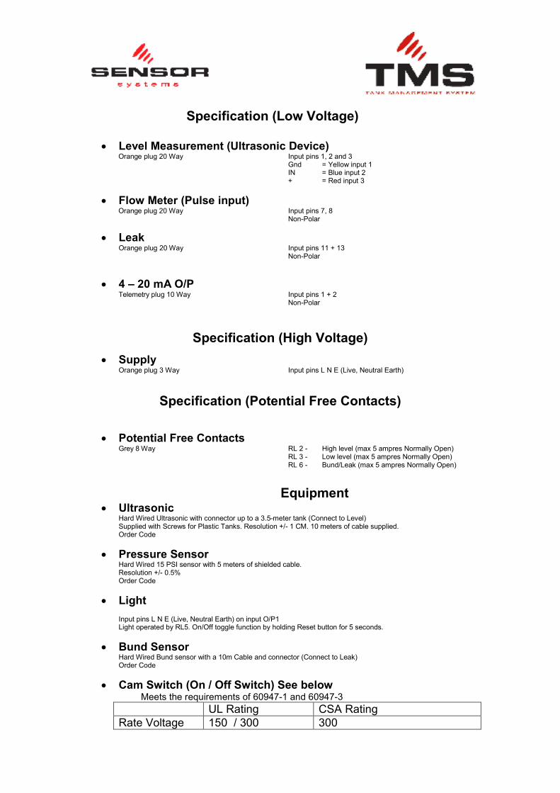
Specification (Low Voltage)
• Level Measurement (Ultrasonic Device) Orange plug 20 Way Input pins 1, 2 and 3 Gnd = Yellow input 1 IN = Blue input 2 + = Red input 3
• Flow Meter (Pulse input) Orange plug 20 Way Input pins 7, 8
Non-Polar
• Leak Orange plug 20 Way Input pins 11 + 13 Non-Polar
• 4 – 20 mA O/P Telemetry plug 10 Way Input pins 1 + 2 Non-Polar
Specification (High Voltage)
• Supply
Orange plug 3 Way Input pins L N E (Live, Neutral Earth)
Specification (Potential Free Contacts)
• Potential Free Contacts
Grey 8 Way RL 2 - High level (max 5 ampres Normally Open) RL 3 - Low level (max 5 ampres Normally Open) RL 6 - Bund/Leak (max 5 ampres Normally Open)
Equipment • Ultrasonic
Hard Wired Ultrasonic with connector up to a 3.5-meter tank (Connect to Level) Supplied with Screws for Plastic Tanks. Resolution +/- 1 CM. 10 meters of cable supplied. Order Code
• Pressure Sensor Hard Wired 15 PSI sensor with 5 meters of shielded cable. Resolution +/- 0.5% Order Code
• Light Input pins L N E (Live, Neutral Earth) on input O/P1 Light operated by RL5. On/Off toggle function by holding Reset button for 5 seconds.
• Bund Sensor Hard Wired Bund sensor with a 10m Cable and connector (Connect to Leak)
Order Code
• Cam Switch (On / Off Switch) See below Meets the requirements of 60947-1 and 60947-3
UL Rating CSA Rating
Rate Voltage 150 / 300 300

Ampere Rating 16 /30 16
Important Warning Notes 1. The TMS must not be used to monitor Petrol 2. It must not be sited near petrol or in any hazardous zone 3. Installation of this equipment must be carried out by a qualified
engineer 4. The installation must conform to all electrical and local authority
regulations and standards.
Product Description The Tank Monitoring System is an electronic gauging system with integrated overfill, bund and low level alarms. The system can use a number of different level sensor (depending on accuracy required) to gauge the contents of a liquids storage tank. Normally open outputs provide the user with the facility to determine when pre determined points have been reached or when a leak has occurred.
Power Supply The TMS is designed to have a continual 230Vac supply fused at a rating of 6-ampere max. The supply should be fused at source, as there is no high voltage protection provided on the TMS.
Operation
• Level Display shown in Litres, and bar chart along bottom
(*Note: The level of any tank is indicative only and a high degree of resolution is not possible with out the use of specialist sensors. If a high degree of resolution is required the user may well need to purchase a pressure sensor)
• Low Level When the level of fluid in the tank reaches the predetermined low level trigger point the triangle in top Left-Hand corner of Display and 1st section of the bar chart will flash. RL 3 will close and stays closed until the level goes above the threshold set point.
• Overfill Alarm When the pre defined over fill level goes above the user set threshold, the buzzer sounds and Alarm LED activates. RL2 will latch into a closed position until the condition is satisfied. To switch the Buzzer off, press the ‘Reset’ button the bar chart on the display disappears and ‘STOP’ flashes. It stays in this state until the level falls below the Overfill Level.
• Leak Alarm When the leak sensor becomes immersed in fluid the Leak alarm will activate and RL5 will close. A Triangle and the ‘Leak Alarm’ symbol is displayed on the ‘Main Screen’. The buzzer will sound and the Alarm LED will activate, to switch off the buzzer, press the reset switch. The alarm will only be reset when the

leak sensor is no longer immersed in fluid. The minimum time for the leak alarm to sound will be 60 seconds.
• Level Connection Alarm This means that the connection between the ultrasonic sensor and the TMS has been broken or it is wired incorrectly. A Triangle and the ‘Level Alarm’ symbol is displayed on the ‘Main Screen’. The last good level received is also displayed. The buzzer will sound and the Alarm LED will activate. To switch off the buzzer, press the reset switch.
• Leak Error Alarm This means that the connection between the leak sensor and the TMS has been broken or it is wired incorrectly. A Triangle and the ‘Leak Error Alarm’ symbol is displayed on the ‘Main Screen’. The buzzer will sound and the Alarm LED will activate, to deactivate the buzzer press the reset button.
• Test Function The output functions and alarm functions can be tested by holding down the reset button and powering down and the powering up the unit while the test button is still pressed. The relays will remain closed as long as the user holds the button down.
• Flow Mode When the user starts to dispense fuel the TMS screen will revert to “Flow Mode”. This mode indicates to the user how much fuel is being dispensed. In the top right hand corner the cumulative total of fuel used is shown while on the screen the overall total is highlighted. The user can manually switch between flow mode and normal contents mode at any time by pushing the reset button. Contents mode is displayed 1 minute after the flow meter stops. Note: if the reset button is toggled during flow mode it will reset the flow to zero.
Variable Software Settings
Default Settings (these are variable using ‘Yellowman’; 1. Low-level alarm - 485 Litre 2. High-level alarm - 4700 Litre 3. Pulse settings – 90.9 (imp/L) 4. Alarm Settings - On 5. Hysteresis – 1% 6. Panel - (Off) 7. Light – (Off) 8. Tank Capacity – 5000L
Software Version 2.37a
Warranty
Sensor Systems warrants to the end user that its products will be free of defects in material and craftsmanship for a period of ONE YEAR from the date of manufacture. Sensor Systems will rework or replace the product and return to the customer at Sensor Systems expense. The Warranty becomes invalid if the unit has been mishandled, stored in the wrong conditions or installed by an unqualified person. Sensor System will not warrant products which were/have been: Used outside the functional and environment conditions for which they were designed. Physically abused, incorrectly handed/installed. Subject to “Act of God”, e.g.: lighting strikes, flood or any other catastrophic event beyond Sensor Systems control. Any product deemed damaged by the customer shall be returned to Sensor System’s facility at the customer’s expense. Sensors Systems shall not be liable for any cost in relation to the returned products. The purchase invoice and description issue should be should be joined with the faulty product. The product should be returned directly to Sensor Systems. © Sensor Systems Ltd