o RATING INSTRUCTIONS, PARTS and MAINTENANC · PDF fileRebuilt SINGER Class 31 Machine 15...
25
o RATING INSTRUCTIONS, PARTS and MAINTENANC ROC OUR FOR CONSEW MOD L 30 SEWING MACHINE CONSOLIDATED SEWING MACHINE New York {California
Transcript of o RATING INSTRUCTIONS, PARTS and MAINTENANC · PDF fileRebuilt SINGER Class 31 Machine 15...

o RATING INSTRUCTIONS, PARTS and MAINTENANC ROC OUR
FOR
CONSEW MOD L 30 SEWING MACHINE
CONSOLIDATED SEWING MACHINE New York {California
- 1 -
SETTING ]P THE ~~CHINE .
Carefully unpack machine from packing case and make sure that all small parts and accessories are removed from packing material.
Wipe machine clean of protective grease and lubricate oil holes with a good grade of sewing machine oil. (see BelmlT)
CAPAQJTY AND SPE~Q
Maximum operatinr:; speed after a break-in period is 2000-2200 stitches per minute depending, of course, on the type of material being sewn, its thickness and that of the seams being crossed.
To assure durability and trouble-free operation it is imperative that for the first several weeks of operation the maximum speed is held t,o not more than 2000 RPM in order to allow the parts to become nroperly broken in.
DIR~CTIOlll OF ROTATION - ..... ----.-,--=----,~ In operation the handwheel of the machine alwavs turns toward t.he operator. To avoid tangled threads and jamming of the sewing hook, do not turn handwheel other~/lIise"
OILING ._' .......... _---Do not operate the machine, even if only for testing, unless it has beenproDerly oiled at every spot requiring lubrication. The following illustrations indicate these spots.
Oiling must be done at least twice daily 1·vhen the machine is in continuous operation to assure free runninf, and durability of the operating parts.
NOTE=--During the break-in period a new machine should be oiled more frequently.
LUBRICATION CHART .... _----..-- .., ,,--~. ,
The lubrication chart (see fig. 1) prescribes lubrication maintenance. The service interval specified on t.he lubrication chart is for normal operating conditions. Failure will result in malfunctioning or damage to the machine. The lubricant prescribed for use on the machine is an all-temperature lubricante
Lubrication points are readily located by reference to the lubrication chart, which is supplemented with individual photographs of the points of lubrication (see figs" 2 to 5). Wipe lubricators and surrounding surfaces clean before applytng lubricant.

Arm Shaft
LUBRICATION CHART
MOD. CONSEW SEWING MACHINE Also
Rebuilt SINGER Class 31
Machine 15
Arm Shaft
Connecting Rod! =----""::::::::::-:?,1Fr~?>~l _____ ---1r---, .ft-------Thread Take-up Lever
Bobbin Winder Frame Oil Well (See Note)
Bobbin Winder Frame-Hinge Pin (See Note)
Oscillating Drive Rock Shaft
Lifting Lever Connecting Rod Joint
Hinge Pin
Needle Bar
Presser Regulating Thumb Screw
Thread Take-up Lever Link
Presser Foot Spring
Presser Bar
Needle Bar Connecting Stud
Lifting Lever Hinge Serew
Oscillating Shaft
Feed Lifting Rock Shaft Connecting Rod
Oscillating Shaft Crank Connecting Rod
Oscillating Shaft Crank Slide Block
Feed Forked Connecting Rod
. Bell Crank Pin
Bell Crank Spring
-- NOTES-
The machine should be oiled twice a day by' applying from one to three drops of lubricating oil 0" to each of the oil can points indicated above by an arrow. Do not flood these moving parts with ojl nor ignore the four hour lubricating interval.
BOBBIN WINDER-Every day lubricate the bobbin winder frame oil well and bobbin winder frame hinge pin with one or two drops of lubri~ eating oil iJilI).
FACE ASSEMBLY-Every week the face plate should be removed and the uncovered bearings and joints lubricated with two or three drops of lubricating oil fl'IIiIII).
SHUTTLE RACE-Twice every day apply lubricating oil _ to the shuttle bearing in the shuttle race, at the same time rubbing two or three drops of oil over the surface of the shuttle race itself. Every week remove the shuttle body from the shuttle race, clean and lubri. cate it.
Pi R:. ]

k~~rjcaQt. The lubricating oil used to lubricate the tailoring machine is a highly refined mineral oil with a low Dour pointo Ii:. mav be used in all temperatu!'eso
~UB~I9J1TI9J'J .. .NOTES gr~JNpr..Y::tJLUJiL UNITS AND PARTS
(a) Ttvice daily, add one to three drops of lubricatinp; oil to the followin~ parts: 1" Needle bar. 2. Needle bar connecting stud. 30 Presser bar. 4. Preseerfoot spring. 5. Presser regulating thumbscrew. 6. Thread take-up lever hinge pin. 7. Thread take-up lever link.
(b) Every week, remove the faceplate, clean the assembly, and lubricate the follo~Tin~ moving parts with two or three drODS of lub:ricatinp: oil to supplement the surface oiling of the machine (fig. 3i. 1. Needle bar connecting stud roller. 2. Thread take-up crank. 3. Thread take-up lever crank. 4. Thread take-up lever hinge pin. 5" Thread take-up lever link hinge pin.
Arm jlsseI11J2ly.o T>lfice a day, add one to three dJ~ons of lubricating oil to the following moving parts:
(a) Arm shaft (to be lubricated through four oilholes). (b) Feed connecting link. (Loosen the thumbscrew in the round
cover plate on the back of the upr:i.ght and turn the cover plate up to lubricate linko (see fig. 2).
(c) Feed lifting rock shaft crank conne cting rod" (See note in (b) above.)'
(d) Lifting lever connecting rod jointo (e) Lift,i ng lever hinge screw. (f) OSCillating rock shaft. (~) OSCillating shaft 0
13i!£LJ?')2.~?}1lb.lY. Twice a day, lubricate the following movinp; parts with one to three drops of lubricating oil ( i:
(a) Bell crank pine (b) Bell crank springo (c) Feed bar. (d) Feed drive connecting rod. (e) Feed lifting connecting: rod" (f) Feed lifting rock shaft. (g) Feed rock shaft@ (h) Oscillating shafto (i) Oscillating shaft crank connecting rode (.j) Oscillating shaft crank sljde block.

- 5 =
If the feed dog stands too high, or if it is out of time with the needle, make the necessary adjustments in accordance with instructions on page 18.
STITCH-ADJUSTING SChEW -------,~
The feed-regulator thumbscrew (11, fig. 6) on the front of the arm regulates the length of the stitch. To change the length of the stitch, loosen the thumbscrev-r and move it doltm to lengthen the stitch, and up to short,enthe stitch. Wnen the desi rpd length is being sewed, tighten the screY-T.
Ref. Consew Singer NO e Part # Part #
1 2 3 4 5 6 7 8 9 10 11
128 222 157 133 115 201. 190 188 126 222 167
688 52339 12409 52454 J56'O 19336 26603 26605 190 52339 818
~Tomencl.Slt.1lr.e.
Pressure rpgulatinc thumbscrew Left-hand spool pin Thread take-up lever Thread retainer Tension regulating thumb nut Presserfoot Feed dog Throat plate Needle 6lamn screw Rif,ht-hand spool pin Feed regula to'!" thumbscrew (for
regulatin~ length of s.titch)
Refo NQ.J!
1 2 3
,
Part No .,~
() (I & 0
15278 5C)lF 2996 62740 15140 2973 2974
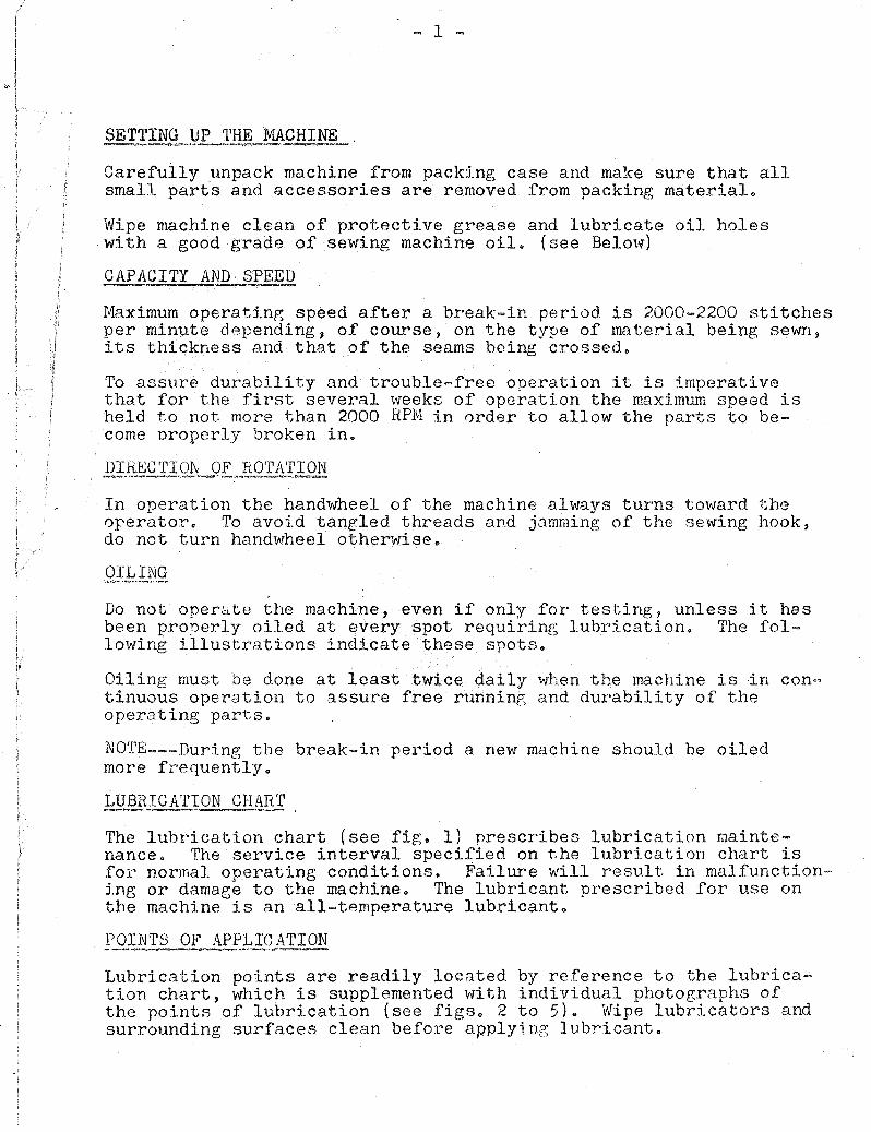
- 7 -
Shuttle bohbin case position finger Shuttle tension spring Shuttle tension regulating screw Shuttle bobbin Shuttle bobbifi case, complete Shuttle bobbin case latch Shuttle bobbin case latch lever Shuttle bobbin case latch lever
fulcrum
E..i.gg~r~_ .e,\l.- ~ShY-t~lf?~ _b9 bPl!LQ.?'§~-':'Yt.i.tb~~_s"~ rf.!]!!_d~J v:e~_ .. tndi ca tjN:;......sh1):l'-.tlS1. teJ11?J_Q.rLr_eg~~.J-ru,ln..p:.. §'Ql:!tr!o
REMOVING BOBBIN -~"I>-""",""",,------.""-.--
a" Turn the balance ~lhe01 toward Y0P unt:i.l the needle moves up to its highest point"
b .. Draw out the slide (view plate) in the bed of the machine" c" Heach under the stand tOPe Wit}: the thumb and forefin(Cl'er of
the left hand., open the latch on the bobbi.n case (see fig"ljj and, holding the bobbin case by the latch, lift it to the left and out of the shuttle race.
do As long as the latch is held open, a sliding lug inside the bobbin case 'holds the bobbin ineide the case.. When the bobbin case is turned open-sidp. do'm, and the latch is released" the bobbin will drop out" Do not tr:T to force the bobbin out of the case while the latch is open"
!~Nj)ING .E0®1N
To wind thread on bobbin, prcc,eed as follows: ao Place the bobbin on the bobbin winder spindle and push it on
as far as it ''fill go, as illustrated in figure 9 .. bo Pass the thread from the bobbin thread cone (m the thre~d stand
dovln throue:h the thread hole in the tension bracket ('9 ~ fig09) and down between the bobbin winder tension disks (1, figG9)
Co Pull the thread from the lo\';er side of the tension disks to the bobbin (12, fig" 9) •
- 9 -
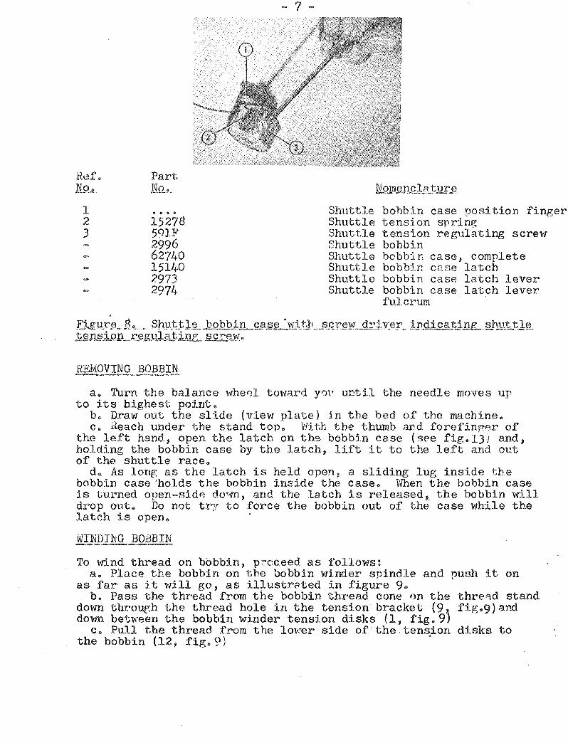
a" Figure 10 shovrs the relative positions of the bobbin case, bobbin, and thread when the bobbin is put into the bobbin case" The thread should draw over the top of the bobbin and from left to right just before the babbin is slinped into the case"
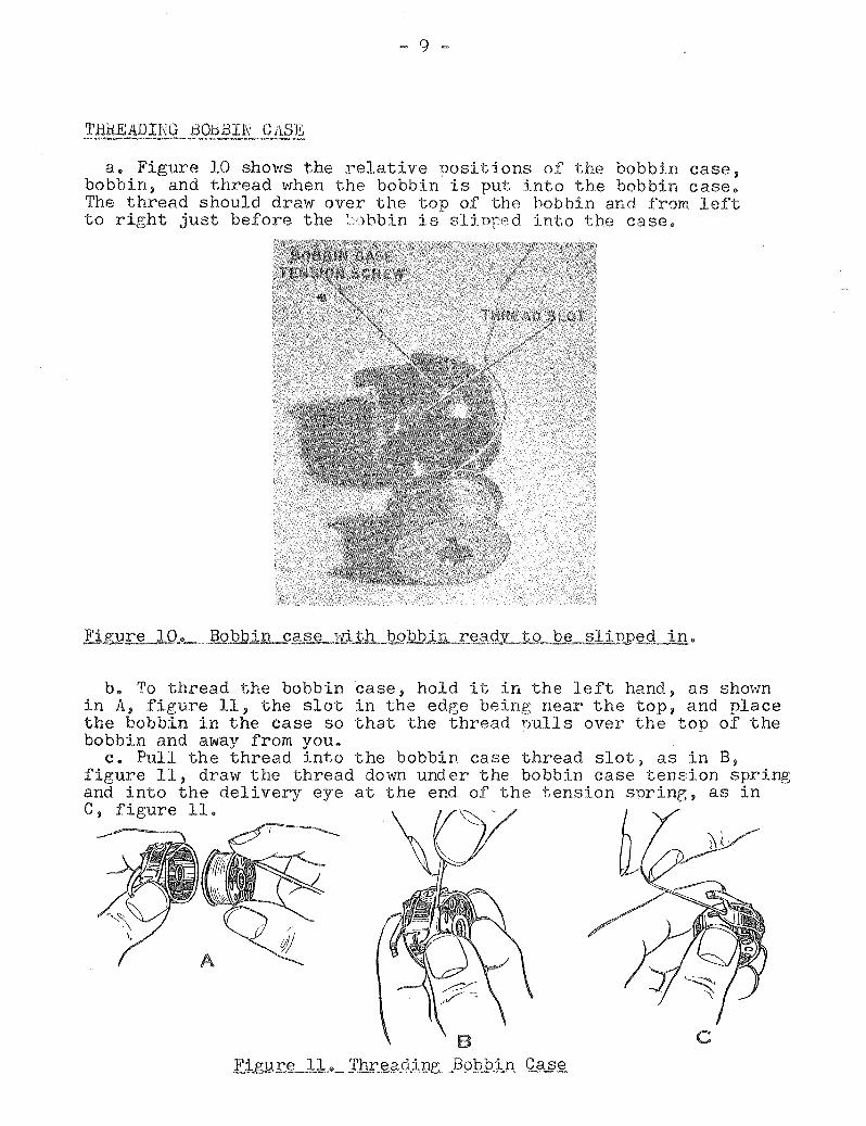
b" To thread the bobbin case, hold it in the left hand, as shov-m in A, figure 11, the slot in the edge being near the top, and place the bobbin in the case so that the thread Dulls over the top of the bobbin and away from you"
Co Pull the thread into the bobbin case thread slot, as in B, figure 11, draw the thread down under the bobbin case tension spring and into the delivery eye at the end of the tension sprine, as in C, figure 11.
c

- 11 -
Remember--uneven, knotted or rough thread imnairs the satisfactory sewing performance of your machine.
Only left. twist thread is to be used for the needle" To test for t1rfist hold a length of thread between thumbs and index fingers of your hands. Turn thread counterclockwise. If it will t1;vist tighter, it has a left twist. If it unravels, it has a right twist.
The bobbin cen be wound with either left or right t1"1ist thread.
NEEDLE AND THjl.EAD CHART
Needle Size
SETTING NEEDLE --_#_-
11 14 16 Ie 20 22
Thread Size (Cotton)
80-100 60-70 40-60 30-40 24-30 16-24
a. Select a good needle of the proper size as explained abovee Never use a bent needle or one vJi th the point blunted or turned. Set the needle \'lith the long groove to the left.
b. To set the needle, turn the balance wheel toward you until the needle bar moves up to its highest Doint.
c. Loosen the needle clamp screw (9, fig. 6), put tbe shank of the needle up into the clamp as far as it will go, and tUrn the long groove of the needle so thRt it faces to the left and is directly in line with the arm of the l1k1.chine.
d" Tigbten the needle clamp SC1'e',"1. If the screw is too loose, the needle will turn or slir.
Figure 13" Bobbin case in shuttls race, with bobbin thread ready to be nicked UD by ~0edlp tl~ead.

~ 13 -
ao After the needle has been thread.ed and the bobbiE case reDlaced, the operator must use the needle thread to catch and draw the bobbin thread up through the hole in the throat plate, as illustrated in fig.15.
bo By operating the hand lifting lever, lock the :Dresserfoot in it.s raised position.
c. With the left hand; hold the end of the needle thread a little slack. d. With the right hand, turn the balance wheel down toward you until
the needle moves from its highest position down and back up to its highest position. If the needle thread is held with a lir;ht tension during this operation, and if the needle is correctly timed, it vnll catch the bobbin threado
eo Draw up the needle thread, and the b0bbin thread w; 1 J. come up wi th it throueh the hole in the throat plate, as in figure 15 .
f. Pull the end of the bobbin thread ent.irely through the hole. Lay both threads back under the presserfoot.
figure 15 2 N§edle :thr~£liLQftiJ1g:.1l§~d,_t9_Jj,x:.avy bobbin _thread up t.hrQ~ hol~ inthroa:t_J2ill~
SEWING
While you are sewing, hold the work flat, but do not pull or push on the materialo Let the feed dog carry the work evenly under the presserfoot and needle .. If the operator pulls on the fabric, the needle bends, strikes the throat plate, and is either dulled or, more likely, broken. INnen the needle is about to cross a seam or other unusually thick or uneven place in the work, disengage the clutch, and hand-turn the machine over the rough place; otherwise, the needle may be broken or throvm out of time •
. :j:NSERTING klORK
Raise the nresserfoot, place the edge of the material beneath the presserfoot, lower the presserfoot, turn the balance wheel by hand until the needle is in the material, and press on the foot treadle to engage the clutch with the motoro The balance wheel should turn over toward you while the machine is operatingo

- 15 -
(6) If bobbin ca.se i3 sticky vlith gummy oil and lint, clean the bobbin case and shuttle race according to page 19 and lubricate it accordinz to instructions on page L~
(7) If there is a sharp edge on shuttle, bobbin case, bobbin, or needle, smooth with fine emery cloth.
d. Skippin~. If the needle thread fails to catch the bobbin thread, the machine will not sew or will leave skips in the stitches. To remedy this trouble, time the needle with the shuttle according to information on nages 19 to 22.
e. Drawing: Qf.....Sec!In. If the threads draw or Ducker the seam, adjust the tensions according to instructions on page 6~
f. 3ii,i tches UP,"~YBI;', or PilesiJ1n.. If the stitches pile UD in one place, adjust the stitch regulstor accardi-ng to page 5. Then ad-just the pres~e t ~Rn2ion ac to page 4.
g l\'~pr11e St-_Y''; 1.:-; T,r;' C:'r'l'd-t'l c -R;:;:~;;..; r:47' ?rf~ t,hp r. .. (-~er1"'.LP st.riK',e- c t,'he o~....... ~_~~::'._~'.i~."", ~ ...... "'v;-" '.f.'---:J;/u .:"-1- ....... &~~ 4.""v __ ~ .... __ v _ ..... _ .. t..J -
shuttle race cap, tigllten the screws ~nich hold the shuttle race. ( ., ,.,- \
> 0ee r:·age 5_.1 e )
he Feed Dog: StrJJ{ __ ;1)}jI~Thr_~Q-.t,, __ tl?:t3,~ If the t'eecl dog strikes the th.!~oa.t plEtte ~ adjust trle f"eed dog' acc()rding to pa~e 18"
ao ";"vfhen the fleedle ~ind ::~}luttle clre correct.11! t5.med, the noir1t of the shuttle on its forward stroke f9.sses across the diameter of the needle at a point of 1/16 inch above the eye of the needle 'vvhen the needle is on its UD stroke, as illustrated in figure 16.

- 17 -
a o No.£.mal_c_Qp"er9j.;i9..lle If the needle is correctly timed with the shuttle, the feed dog (21, fi.gure 18) should be on its down stroke and level vnth the throat plate when the point of the needle reaches the material. If the balance 'AJheel is turned forward, the needle should enter t he material and come back uU o After the
·needle on its UP stroke has cleared the material, the feed dog should then rise above the throat plate and push the material forward the distance of one stitch ..
Ref. Consew Singer No. Part # Part # Nomenclature
1 162 12166 Thread takeup lever hinge pin
2 121 12381 Needle bar 3 127 12391 Presser bar 4 11170 Presser bar spring washer 5 128 688 Presser regulating thumb
screw 6 129 11167 Presser bar spring 7 132 12241 Lifting lever link 8 130 52016 Presser bar lifter 9 131 453 Presser bar guide bracket
set screw 10 136 689 Presser bar lifter screw 11 134 225 S la ck thread regulator
adjusting screw 12 200 190 Presser foot screw 13 123 936 Needle bar screw bushing 14 157 12408 Thread takeup lever 15 159 775 Thread takeup lever cap
screw 16 106 44118 Tension thread controller 17 133 20060 Slack thread regulator 18 131 453 Needle bar connecting
stud set screw 19 126 4303 Need le clamp with screw 20 189 691 Throat plate screw 21 190 208 Feed dog 22 192 12432 Shuttle race slide (view
plate) complete
To time the feed do~, proceed as follows:
(1) See that the needle is correctly set and timed with the shuttle" according to page 15 ..
(2) Loosen and press the feed regulator thumbscrew (11, figure 6) to its lowest pointe The m?chine will then make its longest stitch.

~ 19 -
(1) Loosen screl".i (9, 2J) and move the crank (6, fig. 20 ), up or down, as neces;:;2ry.
(2) Tighten the screw, and test the adjustment by hand-turning the balance wheel forward.
(3) i\. change in the height of t.he feed doe; may throw the nee(Ue and feed doe out of tj~e. Therefore, check and adjust the timing of the needle and feed dog as necessary, according to paragraph
[I.ElvlOVIhG: CLEA~al\JG, AliD filiPLACIl\g._§h~1'TL£RilQK.-_A_SSEIIIII?LY
a. Normal OpeX.i2tiQD_ . .'2.f.. .. 9IlUt tJ-e.. The shuttle race, which is held in place by the two screws, illustrated as 5 in fig. 20, does not move but holds the shuttle body (7, fig.23). As the shuttle body is oscillated back and forth inside the shuttle race, the point of the shuttle borly catches the needle thread above the eye of the needle and forms the loop, which is t,ightened into a lock stitch by the thread take-up lever on its tip stroke.
Ref. Consew Singer No. Part # Part # Nomenc 1a t ure
1) 231 307 (Feed rock shaft screw ) center
2) 1513 (Feed rock shaft screw center nut
3 224 12368 Feed bar 4 215 24412 Shuttle bobbin case po-
sition plate screws 5 219 145 Shuttle race screws 6 227 12376 Feed lifting rock
shaft crank 7) 231 307 (Feed lifting rock
) ( shaft screw center 8) 1513 (Feed lifting rock
shaft screw center nut
9 157 Feed rock shaft crank clamping screw
.E.ig1J.r~ 20.1_ Left end of bed assembly ..
b. RemovinK.and G].eaning Assemh'.'.r. To clean the si1uttle body and shuttle race or to instnll nev parts in the shuttle race assembly, remove the shlJt.1:le rece a03emb). If the needle and shuttle are in ti~e, the shuttle driver and needle can be brought into the correct posj.tions for removing the i3huttle ~c[{ce assembly by turninG the ba1-,1nCG fon'Jard unt.:d tt;.e needle bar is at its highest point. If the needle and 3h')1.: tIe are not in time J the shut [,Ie driver (,'JUst be br01~ght into the right posi tioD by turning the balance wheel unt il the driver, \'JY::.le st~.ll in the shut tIe race, is in the position shown in fig. 21. This position is imnortant because the shuttle race assembly cannbt be disengaged from the shuttle driver if the driver
= 21
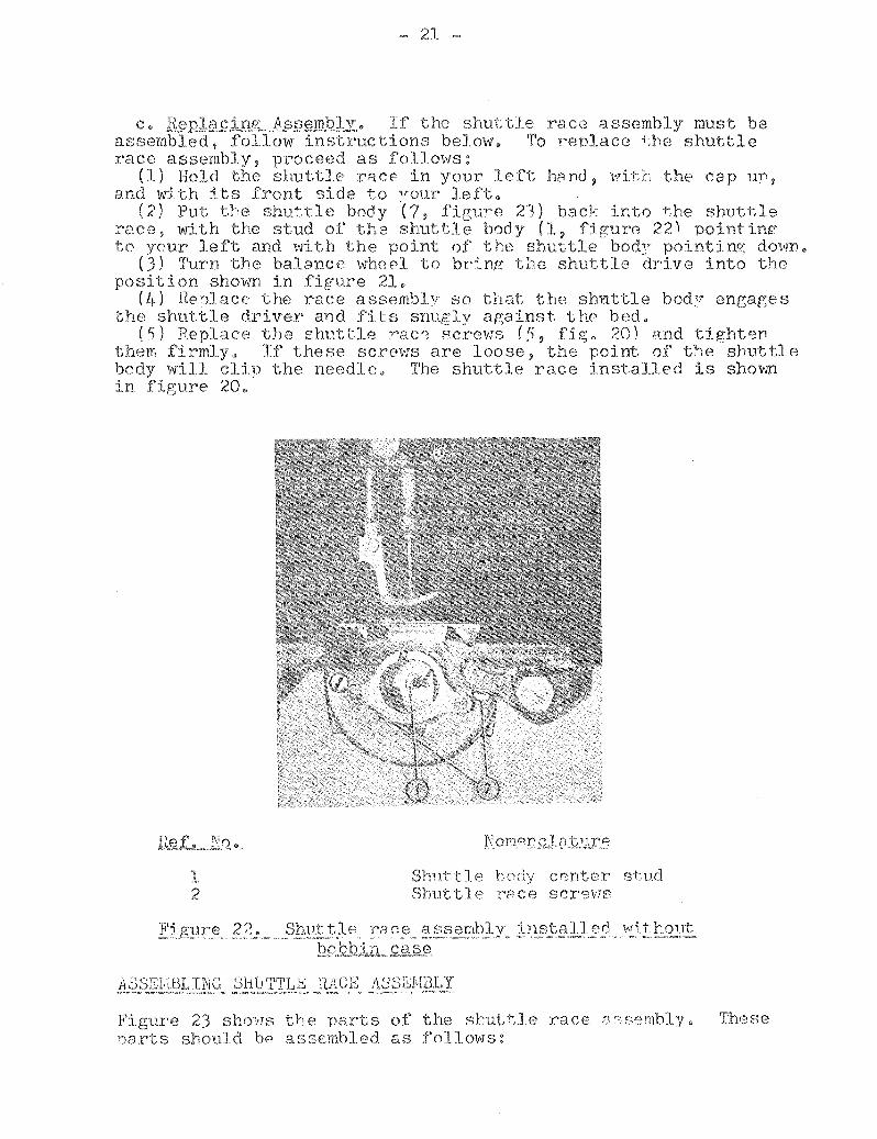
c. R§.pJ£t.£!inz,jLs§s;J!.l.QJJ~,. If the shut tIe race assembly must be assembled, follow instructions below. To renlace ~he shuttle race assembly, proceed as follows:
(1) Hold the shuttle rA.ce in your left hand, i,~rit:r the cap 11'0,
and with its front side to your left@ (2) Put the shuttle body ~7, figure 21) back i~to the shuttle
:i'acs, with the stud of the shuttle body (1, fjgure 22) pointinr: to your left and \!'nth the point of t he shuttle bod;' pointi ncr; dOvI/TI"
(J) Turn the balance ''''he!.''l to bri .. ng the shuttle drive into the position shoil,'!l in figure 21.
(4) He;)lact' thE} race assembly so that the shuttle bod-:T eneages the shuttle driver and fits snugly against the bed.
(5) Replace the shuttle ~aC0 screws (~, fi~. 20) and tighten them firmly" If these scrOVJS are loose, the point of t"l.e shuttle body will clip the needle. The shuttle race installed is shovln in figure 20"
1 2
Shuttle body cronter s+:,ud Shuttle race screws
Fie:ure 22. Shll.ttle race ::tsser.i.blV installed 1tJ~.ttout ='~~~"""'~"_' _="",,,,~"~_,,,~,~,_,",,,~,,,~~_._. , _ '-"<r="'"_""=_~"~',,''<'''''''''-·<.-$><''-_~,,",'''''",,,,_~_h ~ _'=--_~-'="""_"""
129,.9 b t.lL-,s;::.as e.
ASSEl,it3LING SHuTTU~ ~:~ACE 1\DS;~I\Il:3.LY <~,_~~~_"" ''''''''='~'<:>~'''''' ~=,"""-'"' .~ "'" =._~_._"·"<> .. r'_ .. """" , -..-. __ . ____ .. ~ ... -,or _O<I>_"'~_,-
Figure 23 sho'!JS the parts of the stutT,le rac€: Dr::semblyo 'rhese 1')8 rts should bp assemhled o.s follows:
~ 23 -
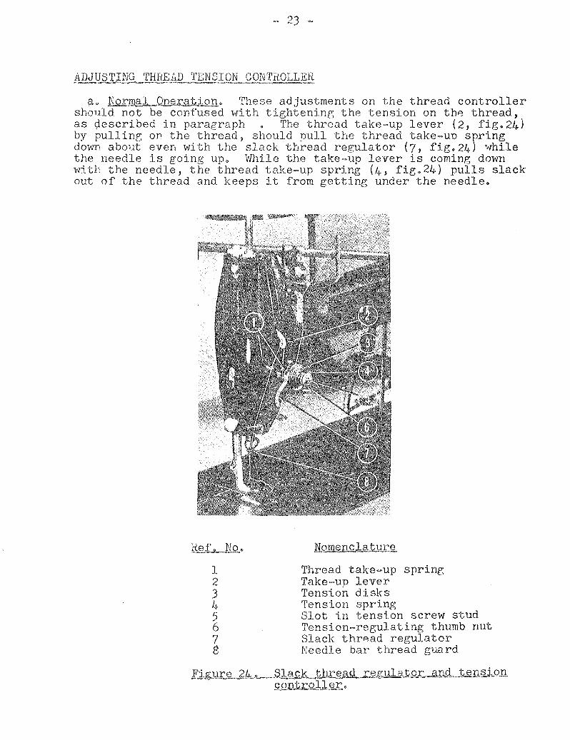
~o No~~~ra1ion. These adjustments on the thread controller should not be confused with tightenine the tension on the thread, as ¢escribed in paragraph • The thread take-up lever (2, fig.24) by pulline on the thread, should pull the thread take-uD spring down about even wi th the slack thread regulator (7, fig. 24) l.vhile the needle is going up. While the take-up lever is coming down with the needle, the thread take-up spring (4, fig.24) pulls slack out of the thread and keeps it from getting under the needle.
1 2 3 4 5 6 7 8
Thread take-up sprinr, Take-up lever Tension disks Tension spring Slot in tension screw stud Tension-regulating thumb nut Slack thread regulator Needle bar thread guard
Figure ~.~Jlll<Legulalo;r: and tensi.on Q,ont;r:o].ler.

- 25 -
C e QJ:l:1.ngjne-1.e.Rs;i,P1L sl:L.?lrril1.£:" The tenston of the thread take-up spring should be just sufficient to take UP the slack of the needle thread until the eye of the needle on its do'W11 stroke reaches the materi.ale To change the tension of the thread take-un spring (l, fig q24 and 4, fig. 26), proceed as follows:
(1) Loosen the tension regulating thuPlb nut (6, fig. 24) and force the take-un snring (1, fig.24) from the recess in the regulator. You do not have to tG.ke the regulator assembly out of tlH~ machine, but you can see the recess in the regulator in 2, fi~. •
(2) To increase tl-,e tension on the spring, i"'ind the spring to the right between the regulator and the back tension disk.
(3) To decrease the tension on the spring, wind the sprinr to the left between the regulator and the back tension diske
(4) When the spring is i'JOund or unwound enough to put the correct tension on it, fnrce the spring back into the recess jn the regulator and tighten the tension regulating thumb nut (6, figure24).
d. ReI1lQvi.ngJh~~.lJ.:!k~:::lUL§nrin.g0 To remove the th-read take -up spring (1, figure 24) insert a screw driver in the slot of the tension screw stud (5, figure2~ and turn the stud to the left until it is screvfed out of tbe threat take-un spring regulator (2, fig. 25 ).
e" AS_~£,J!)~b;;::eaQ..l!ontro..JJ.er" Figure shows the order in \1"hich the narts of t.be thread controller shou.ld be assembled" Adjustments ~re eX1)Jained in a through c above"
1
2 3
4 5
Thread take-un sy-;rinp: rer~lJ-lator setscrew . ~
Slack thread rep::ulator Tension-regulatinp' thumh nut on thA tenst~r screw
stud Thread take-up spring Thread take un lever

SINGER PART NO.
448 12389 12444 1266 44134 2049 453 12481 691 12481 208 12432 725 4307 12411 12369 12464 12450 19336 190
12335 12142 24982
120807 120804 35137
12393 62740 2996 24413 24412
391 2531 2533 907 145 24415
52239 12453 12368 313 ) 1519) 44125 12376
12379 29633
CONSEW PART NO.
181 182 183 184 185 1'86 187 188 189 190 191 192 193 194 195 '* 196 '* 197 'I<
198 * 199 200 201 '* 202 '* 203 '* 204 '* 205 * 206 * 207 * 208 '* 209 11
210 211 212 213 214
215 216 217 218 219 220 221 222 223 224
225
226 227
228 229
DESCRIPTION
Set screw for #180 Oscillating shaft
shuttle driver Set screw for #183 Oscillating shaft crank Pin for #185 Set screw for #185 Throat plate Screw for #188
-27-
SINGER PART NO o
1813
l~h 12237 80~
12'116
12240 44[1
Feed dog for #188 Screw for #190 Shuttle cover plate Screw for #194 shuttle cover plate Throat plate
S5~'8
spring 5735
Feed dog for #195 Throat plate Feed dog for #197 Presser foot Screw for #199 Presser foot-zipper Presser foot n
" II
II
Hemming foot - wide
" - narrow Presser foot with guide Presser foot-zipper
with guide Oscillating shuttle
17i'l 25;431
#9x1-1/B
12358 448 24297 210
" bobbin case Bobbin Shuttle race body Shuttle bobbin case
position plate Screw for #214 Shuttle race back n spring Screw for #217 Shuttle race body screw
complete Needle 16 x 87 (Cat.20S5) Spool pin Oil feed tube
12362 12361
#14xl-l/8 120342 26026
26485
8879 36072 25866
Feed bar 25874
Screw Center & Nut for #224 732
Feed lifting rock shaft Feed lifting rock shaft
crank 'Feed rock shaft .. .. crank
44212
CONSEW PART NO.
230 231
232 233 234
235 236
237 238 239 240 241 242 243 244 1<
245* 246 247 248 249 250 1<
251 '" 252 '*
253 *
254 1<
255 256 257 258 259 260 261 262 263 264 265 266
267
268 269
DESCRIPTION
Roller stud for #227 Screw center & nut
for #226 and #228 Lifting lever Hinge screw for #232 Lifting lever hinge
connection Hinge screw for #234 Lifting lever connecting
rod with nut Lifting lever pin Set screw for #237 Bell crank
spring Screw for #239 Bobbin winder, complete Wood screw for #242 Bobbin winder---complete
foot treadle operatic only
Wood screw for #244 Balance wheel set screw for #246 Balance wheel oil cover Screw for #248 Balance wheel - foot
treadle operation onl
Bushing for #250 Clamp stop motion clamp
washer Clamp stop motion clamp
screw Lock screw for #253 Machine hinge plate
connection Wood screw for #255 Oil can Screw driver - large Accessory Box Screw driver - small Lubricating oil - 3 oz. Spool pin felt Hemmer foot cloth gauge
Screw for #265 and #266
Drip pan Nail for #268
DENOTES SPECIAL ORDER PARTS - NOT STANDARD EQUIPMENT

CONSOLIDAT::<;D SEWING MACIIINJE 1 5 Now York

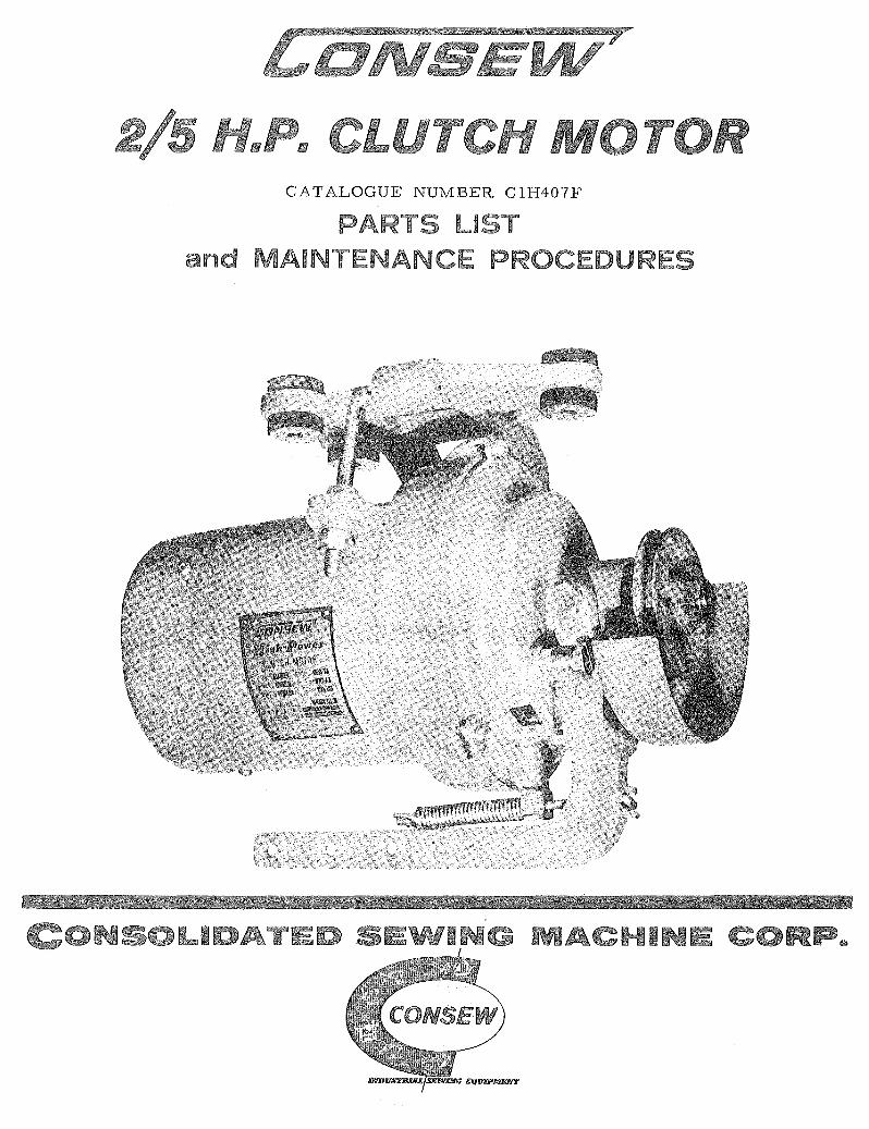
CATALOGUE NUMBER CIH407F
PARTS LIST and MAINTENANC PROCEDURES
I RP~
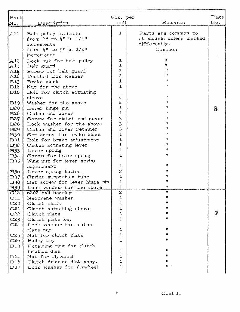
Part No.
All
A12 A13 A14 A16 E13 E16 E18
E19 B20 E26 B27 E28 B29 E30 B31 E32 B33 B34 B35
B36 B37 E38 B39 C12 C14 C20 C21 C22 C23 C21+
C25 c26 013
014 016 017
Description
Belt pulley available from 2" to 4" in 1/4" increments from 4" to 5" in 1/2" increments Lock nut for belt pulley Belt guard Screw for belt guard Toothed lock washer Brake block Nut for the above Bolt for clutch actuating sleeve vvasher for the above Lever hinge pin Clutch end cover Screw for clutch end cover Lock washer for the above Clutch end cover retainer Set screw for brake block Bolt for brake adjustment Clutch actuating lever Lever spring Screw for lever spring Wing nut for lever spring adjustment Lever spring holder Spring supporting tube Set screw for lever hinge pin Lock washer for the above 6202 ball bearing Neoprene washer Clutch shaft Clutch actuating sleeve Clutch plate Clutch plate key Lock washer for clutch plate nut Nut for clutch plate Pulley key Retaining ring for clutch friction disk Nut for flywheel Clutch friction disk assy. Lock washer for flywheel
Pes. per unit
1
1 1 2 2 1 1
2 2 1 1
3 3 3 1 1 1 1 1
1 2 1 1 1 2 1 1 1 1 1
1 1 1
1 1 1 1
Remarks
Parts are common to all models unless marked differently.
Common
ff
tr
" " " "
" " " " " " " " " " " "
" " " " " " "
,/I
/I
" "
" " " /I
" /I
"
Cont'd.
Page No.
7

. ,,,,,..,-,,"'.
Part Pes. per Page No. Description unit Remarks No.
G19 Cast aluminum cage rotor 1 2/Shp. 172Srpm. 1 phase G20 " " " " 1 2/Shp. 34S0rpm. 3 phase G21 " " " " 1 2/Shp. 172Srpm. 3 phase G22 " " " " 1 2/Shp. 34S0rpm. 1 phase
SO/60cy G23 Motor shaft 1 2/Shp. 34S0rpm. 1 phase
2/Shp. 34S0rpm. 3 phase 2/Shp. 172Srpm. 3 phase
G24 Motor shaft 1 2/Shp. 172Srpm. 1 phase 2/Shp. 34S0rpm. 1 phase
SO/60cy G2S Neoprene washer 1 Common H2O Terminal board 1 " H21 Screw for terminal board 1 " H22 Ground screw 1 " H23 vvasher for the above 1 " H24 Terminal stud screw 2 2/Shp. 34S0rpm. 1 phase
2/Shp. 172Srpm. 1 phase H24 Terminal stud screw 3 2/Shp. 34S0rpm. 3 phase
2/Shp. 172Srpm. 3 phase 2/Shp. 34S0rpm. 1 phase
9 SO/60cy H2S Nut for the above 6 2/Shp. 34S0rpm. 1 phase
2/Shp. 172Srpm. 1 phase H2S Nut for the ab ove 9 2/Shp. 34S0rpm. 3 phase
2/Shp. 172Srpm. 3 phase 2/Shp. 34S0rpm. 1 phase
SO/60cy H26 Terminal washer 4 2/Shp. 34S0rpm. 1 phase
2/Shp. 172Srpm. 1 phase H26 Terminal washer 6 2/Shp. 34S0rpm. 3 phase
2/Shp. 172Srpm. 3 phase 2/Shp. 34S0rpm. 1 phase
SO/60cy H27 vvasher for the terminal
stud screw 4 2/Shp. 34S0rpm. 1 phase 2/Shp. 172Srpm. 1 phase
H27 vvasher for the terminal stud screw 6 2/Shp. 34S0rpm. 3 phase
2/Shp. 172Srpm. 3 phase 2/Shp. 34S0rpm. 1 phase
SO/60cy
4
Contld.

832---
836<---__ ......
837 -----831 ~----B39 -----B16
'~---B13
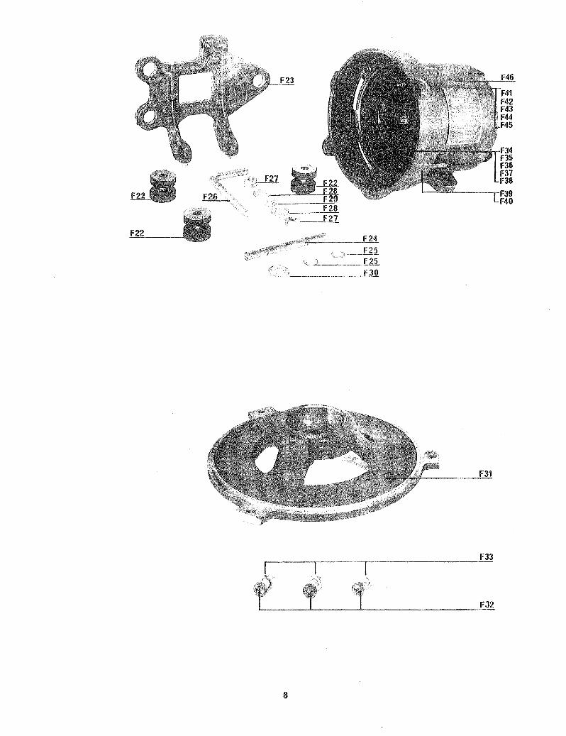
-~%~~~~~~--~ C F25
_. 'Z._.;! f..Zi , ____________ £.3.0.
F33
FJ2
8

LUBRI~TION
Sealed ball bearings, containing sufficiant lubricant for the life of the bearings are installed in the Consew clutch motor@ Therefore relubrication is neither possible nor required o
The only spot requiring occasional lubrication is the clutch operating sleeve o An oil hole (A) is located on top of the projection from the pulley end of the motor e It requires about 2 to 4 drops of lubricating oil SoAeEo 20 or similar Q every 60 dayse
CLUTCH AND BRAKE ADJUSTMENT
If clutch or brake adjustment should become necessary, this is indicated by an excessive travel of the clutch lever or of the foot pedal when starting to operate the sewing machine or upon stopping ito
To adjust clutch and brake, first loosen set screw (B) about 2 turns, then loosen lock nut (C) and turn head of adjustment bolt (D) clockwise one half turn at a time, then test for results by pressing down the clutch lever. Tighten lock nut (c) and set screw (B) upon completing clutch and brake adjustmente NOTE: Do not turn in bolt (D) so far that there is no more clutch action, as this may jam both clutch and motor, causing damage to the motor in particulare
Fig, 1
REPLACING THE CLUTCH LINING
1) Note position of treadle pitman rod and treadle and loosenthe clamp tying together the two component lengths of the treadle pitman rod o
Unhook upper component from clutch lever. Unscrew from clutch motor housing three clamps {E)o This will permit clutch portion to become separated from motor.
REPLACING THE CLUTCH BEARINGS
1) Follow steps 1, 2, and 3a on page 2@
,2) Use a bearing puller, engaging its jaws with the milled grooves in the clutch bearing sleeve (fig. 2), to pull the clutch bearing nearest the pulley end from the clutch shaft. Now push bearing out from inside of bearing sleeve@
3) Clamp thickest portion of clutch shaft with clutch disc attached in a bench vise, flatten out the safety washer (J) under nut (fig. 2) and remove the nut. The clutch disc can now be removed from the clutch shaft: also remove the clutch disc key. Now the second ball bearing can be removed, using the bearing puller@
4) When installing new ball bearings proceed in the reverse order outlined above, first placing the new ball bearing on the clutch disc end of the shaft. Reassemble clutch disc key, safety washer and tighten nut"
NOTE: Do not strike ball bearings directly when installing sleeve on the shaft1 be sure to apply force only to the inner race. When placing the bearings into a bore apply force only to outer race. Check bearing sleeve for burrs resulting from application of puller before reinstallation into clutch head.
TO REPLACE THE MOTOR BEARINGS
1) Follow steps 1, 2, and 3a on page 20
2) Remove three screws (H) and lightly tap flywheel with punch or similar tool, placed through ventilating slots located along~ side the screws. This will cause the flywheel together with th, inner motor endshield and the rotor to come out of the motor housing for easy removal.
3) Flatten the safety washer under the nut holding flywheel, remove nut, lift out flywheel and flywheel key.
4) Using bearing puller, remove ball bearing from the rotor shaft and replace with new ones o
5) Reassemble motor ~nd '"shield and flywheel with rotor and place this assembly into the motor frame, making sure that the rubber ring is placed on the inside of the bearing bore in the motor housing at the side opposite the flywheel.