O-3 - Tratos | Cables for a moving worldtratosgroup.com/wp-content/uploads/2016/06/O3... · ·...
58
O-3 INSTRUMENTATION CABLES CAVI STRUMENTAZIONE
Transcript of O-3 - Tratos | Cables for a moving worldtratosgroup.com/wp-content/uploads/2016/06/O3... · ·...

ALMA S.r.l.Via Stadio, 252036 Pieve S. Stefano - ItalyTel. +39 0575 7941Fax +39 0575 798026
TRATOS CAVI S.p.a.Via Stadio, 252036 Pieve S. Stefano - ItalyTel. +39 0575 7941Fax +39 0575 [email protected]
TRATOS CAVI S.p.a. filiale CataniaXIII Str. Strad. V.LanciaLoc. Piano D’Arci95121 Catania - ItalyTel. +39 095 7482101Fax +39 095 291059
TRATOS H.V. S.p.a.Via Pian di Guido, 4552036 Pieve S. Stefano - ItalyTel. +39 0575 799429Fax +39 0575 796907
TRATOS LtdUK - Park RoadHolmewood Industrial ParkHolmewood - ChesterfieldDERBYSHIRE S42 5UWTel. +44 01246 858000Fax +44 01246 858001
NORTH WEST CABLES LtdSchool lane, KnowsleyMerseyside L34 9HDTel. +44 01515 483888fax +44 0151 549 1169
TRATOS CAVI Iberica S.L.SpainPaseo de los Parques 6, bloque 6, 1D28109 Alcobendas (Madrid)Tel./ Fax +34 91 6255887
O-3
INSTRUMENTATION CABLES
CAVISTRUMENTAZIONE
INSTRUMENTATION CABLES
CAVISTRUMENTAZIONE
Presentation
Tecnical standards cables
Construction and performances
Were to employ cables for instrumentation
Influences
Selection of the screen in relation to the type of influence
Behaviour to fire condition
Examples of instrumentation cables
Screening
Production range
Cable dimensions (British standards)
Cable dimensions (French standards)
Cable dimensions (ENI group standards)
Conductors
Material characteristics
Armourings
Identification codes
Conversion tables
Final tests
Quality system
Packaging
Drum capacity
Presentazione
Norme tecniche di riferimento
Costruzioni e prestazioni
Dove impiegare i cavi per strumentazione
Interferenze
Scelta dello schermo con riferimento al tipo di interferenza
Comportamento al fuoco
Esempi di cavi strumentazione
Schermature
Programma produzione
Tabelle cavi (Standard inglesi)
Tabelle cavi (Standard francesi)
Tabelle cavi (Standard gruppo ENI)
Conduttori
Caratteristiche materiali
Armature
Codici di identificazione
Tabelle conversione
Prove finali
Sistema di qualità
Imballo
Contenuto bobine
3
4/5
6/11
12/13
14/15
16/17
18/19
20/21
22
23
24/33
34/37
38/43
44/45
45
46
47
48/49
50
51
52
53
INDICE
CONTENTS
PagePagina

CAVI STRUMENTAZIONEINSTRUMENTATION CABLES
1 conduttoreconductor
2 isolamentoinsulation
3 schermo individualeindividual screen
4 schermo globaleoverall screen
5 guaina internainner sheath
6 guaina di piombolead sheath
7 guaina internainner sheath
8 armaturaarmouring
9 guaina esternaouter sheath
6 5 4 3 2 1789
4 3 2 1589
4 3 2 1589

Con questa pubblicazione TRATOS CAVI desidera far conoscere a tutti i suoi potenziali clien-
ti i cavi per strumentazione prodotti e commercializzati.
Le normative nazionali e internazionali esistenti presentano soluzioni parziali, spesso non suf-
ficienti per progettare un cavo per strumentazione che soddisfi completamente le aspettative
del cliente.
Un team di esperti è in grado di progettare cavi per strumentazione per qualsiasi applicazio-
ne. La grande esperienza maturata in tanti anni di attività permette di ottimizzare tutte le risor-
se e le informazioni tecniche disponibili che sono registrate in una banca dati che, giorno dopo
giorno, si arricchisce sempre più.
È importante perciò precisare che in questa illustrazione sono indicati, come esempio, solo
alcune tipologie di cavi che TRATOS CAVI produce. Infatti molti altri tipi possono essere forni-
ti con caratteristiche e prestazioni in accordo a particolari standard tecnici del cliente e dell'u-
tilizzatore finale.
Questo catalogo deve essere utilizzato solo come guida generale all' impiego dei cavi stru-
mentazione e tutto ciò che non è in esso riportato può essere fornito su Vostra richiesta.
Through this publication TRATOS CAVI would like to present to all its potential customers the
instrumentation cables produced and sold.
The existing national and international norms propose only partial solutions which often are not
enough to project an instrumentation cable which meets completely the customer's require-
ments.
A team of experts is able to design instrumentation cables for any employment. The great expe-
rience developed in many years of activity permit to attain all the resources and technical infor-
mation available.
A data bank which is growing rich day by day thanks to the service of our laboratories of
research and products development.
It is therefore important to specify that in this illustration are indicated, as example, only some
of the cables which TRATOS CAVI produces. In fact large variety of cables are produced with
characteristics and performances in accordance with particular technical standards of the
customer and the end user.
This catalogue has to be used only as a general guide for the employ of instrumentation cables
and all is not stated in it can be supplied upon request.
3
CAVI STRUMENTAZIONEINSTRUMENTATION CABLES
4
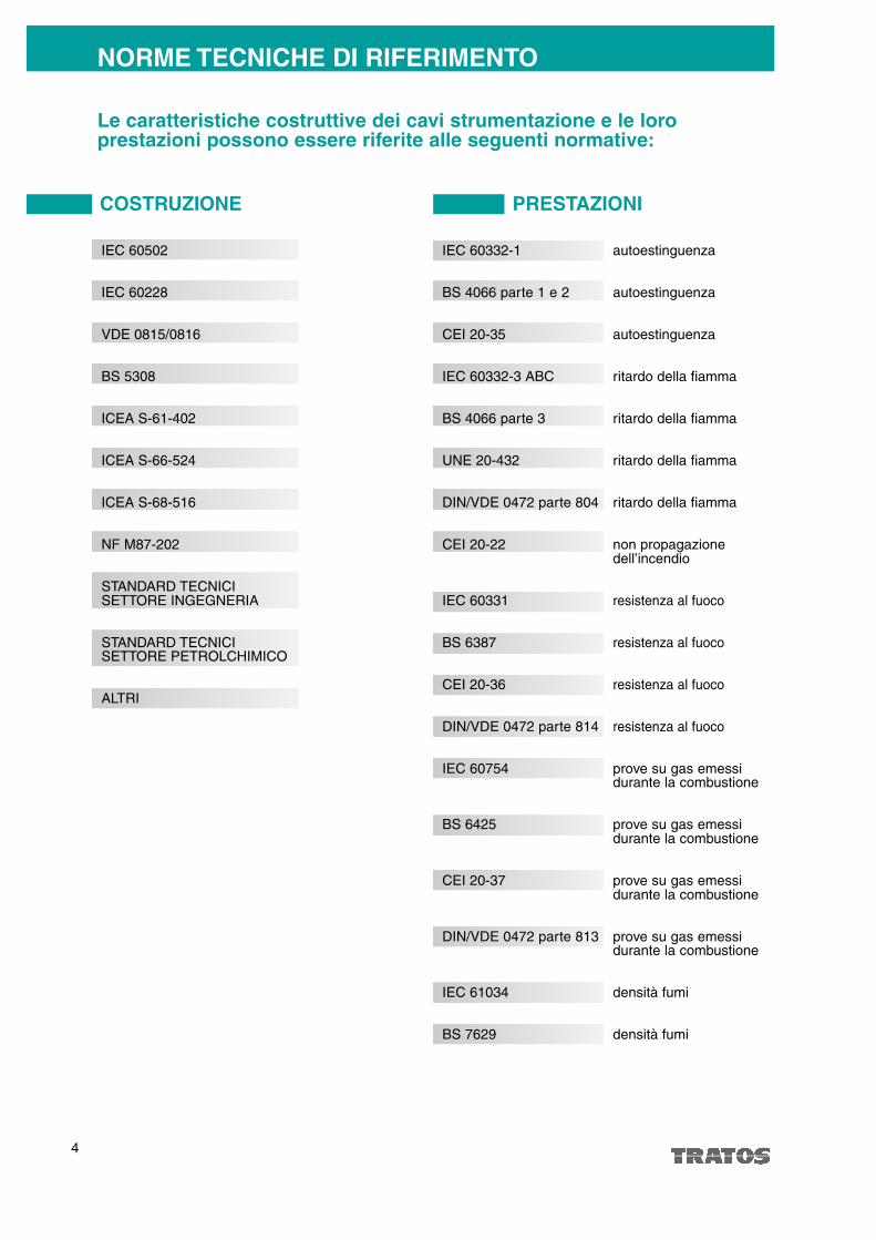
NORME TECNICHE DI RIFERIMENTO
Le caratteristiche costruttive dei cavi strumentazione e le loroprestazioni possono essere riferite alle seguenti normative:
COSTRUZIONE PRESTAZIONI
IEC 60502
IEC 60228
VDE 0815/0816
BS 5308
ICEA S-61-402
ICEA S-66-524
ICEA S-68-516
NF M87-202
STANDARD TECNICISETTORE INGEGNERIA
STANDARD TECNICISETTORE PETROLCHIMICO
ALTRI
IEC 60332-1 autoestinguenza
BS 4066 parte 1 e 2 autoestinguenza
CEI 20-35 autoestinguenza
IEC 60332-3 ABC ritardo della fiamma
BS 4066 parte 3 ritardo della fiamma
UNE 20-432 ritardo della fiamma
DIN/VDE 0472 parte 804 ritardo della fiamma
CEI 20-22 non propagazione dell’incendio
IEC 60331 resistenza al fuoco
BS 6387 resistenza al fuoco
CEI 20-36 resistenza al fuoco
DIN/VDE 0472 parte 814 resistenza al fuoco
IEC 60754 prove su gas emessi durante la combustione
BS 6425 prove su gas emessi durante la combustione
CEI 20-37 prove su gas emessi durante la combustione
DIN/VDE 0472 parte 813 prove su gas emessi durante la combustione
IEC 61034 densità fumi
BS 7629 densità fumi
5
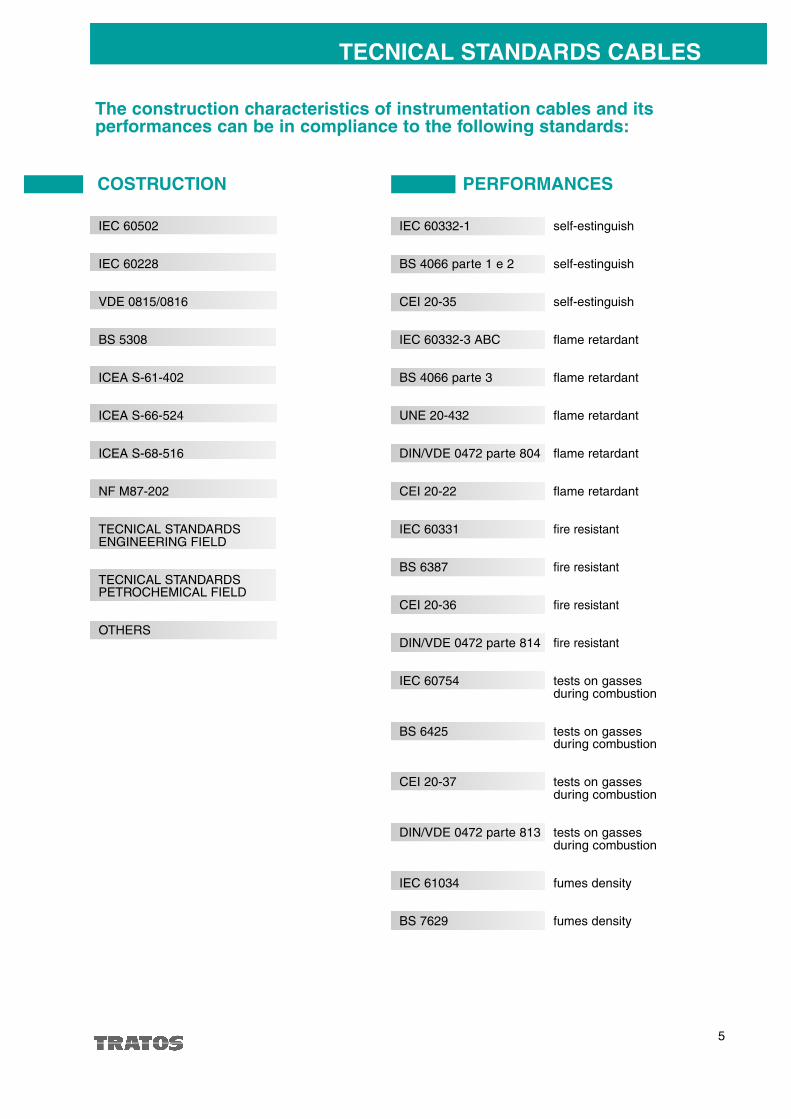
TECNICAL STANDARDS CABLES
The construction characteristics of instrumentation cables and itsperformances can be in compliance to the following standards:
COSTRUCTION PERFORMANCES
IEC 60502
IEC 60228
VDE 0815/0816
BS 5308
ICEA S-61-402
ICEA S-66-524
ICEA S-68-516
NF M87-202
TECNICAL STANDARDSENGINEERING FIELD
TECNICAL STANDARDSPETROCHEMICAL FIELD
OTHERS
IEC 60332-1 self-estinguish
BS 4066 parte 1 e 2 self-estinguish
CEI 20-35 self-estinguish
IEC 60332-3 ABC flame retardant
BS 4066 parte 3 flame retardant
UNE 20-432 flame retardant
DIN/VDE 0472 parte 804 flame retardant
CEI 20-22 flame retardant
IEC 60331 fire resistant
BS 6387 fire resistant
CEI 20-36 fire resistant
DIN/VDE 0472 parte 814 fire resistant
IEC 60754 tests on gasses during combustion
BS 6425 tests on gasses during combustion
CEI 20-37 tests on gasses during combustion
DIN/VDE 0472 parte 813 tests on gasses during combustion
IEC 61034 fumes density
BS 7629 fumes density

6
COSTRUZIONE E PRESTAZIONI
Rame ricotto rosso o stagnato IEC 60228 o equivalenti, classe 1 - 2 - 5Materiale conduttore
Come richiesto dal cliente le sezioni più comuni sono 0,5 - 0,75 - 1 - 1,5 - 2,5 mm2e 20AWG - 18AWG - 16AW G .
Dimensioni
Può essere usato PVC, polietilene, polietilene reticolato, silicone, LSHF com-pound ed altri tipi di isolante. La scelta dipende dai valori elettrici richiesti, peresempio la capacità mutua e da altre caratteristiche quali la temperatura di uti-lizzo, le condizioni ambientali di impiego ecc.
Isolamento
Tutti i cavi possono essere previsti a coppie, terne o quarte. La lunghezza delpasso di riunitura è scelta opportunamente per migliorare i parametri elettricie meccanici. Le coppie, terne e quarte sono definite elementi.
Coppie, terne e quarte
L'identificazione dei conduttori delle coppie, delle terne o quarte si ottiene tramite differenti colori dell'isolante.I colori sono stabiliti tra acquirente e fornitore o dalle norme tecniche di riferimento.La sequenza degli elementi si ottiene numerando uno o più conduttori di ogni coppia, terna o quarta. Quandoi cavi hanno la schermatura individuale si può utilizzare, per individuare la loro sequenza, un nastrino di polie-stere numerato che è parte dello schermo.
Coppia due conduttori riuniti insieme formano il circuito
Terna tre conduttori riuniti insieme formano ciascuno un circuito con l'altro
Quarta quattro conduttori riuniti insieme opposti diametricalmente formano i circuiti
Identificazione delle coppie e delle terne
7
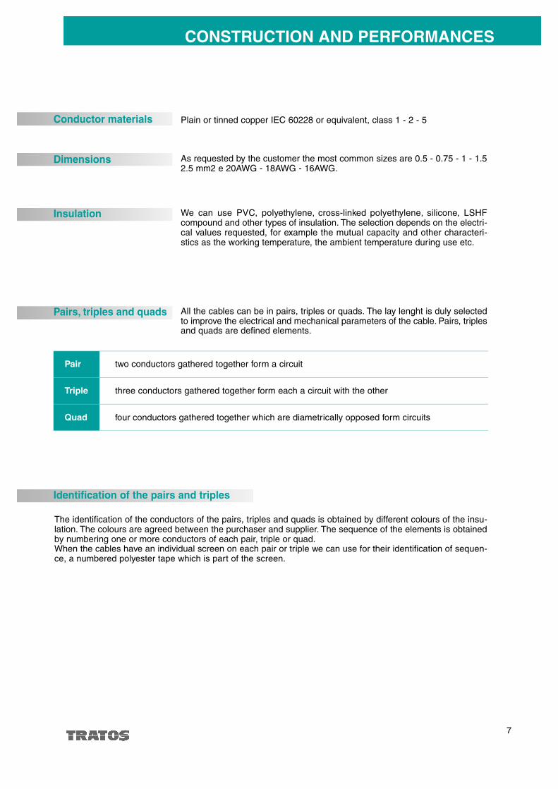
CONSTRUCTION AND PERFORMANCES
Plain or tinned copper IEC 60228 or equivalent, class 1 - 2 - 5Conductor materials
As requested by the customer the most common sizes are 0.5 - 0.75 - 1 - 1.52.5 mm2 e 20AWG - 18AWG - 16AWG.
Dimensions
We can use PVC, polyethylene, cross-linked polyethylene, silicone, LSHFcompound and other types of insulation. The selection depends on the electri-cal values requested, for example the mutual capacity and other characteri-stics as the working temperature, the ambient temperature during use etc.
Insulation
All the cables can be in pairs, triples or quads. The lay lenght is duly selectedto improve the electrical and mechanical parameters of the cable. Pairs, triplesand quads are defined elements.
Pairs, triples and quads
The identification of the conductors of the pairs, triples and quads is obtained by different colours of the insu-lation. The colours are agreed between the purchaser and supplier. The sequence of the elements is obtainedby numbering one or more conductors of each pair, triple or quad.When the cables have an individual screen on each pair or triple we can use for their identification of sequen-ce, a numbered polyester tape which is part of the screen.
Pair two conductors gathered together form a circuit
Triple three conductors gathered together form each a circuit with the other
Quad four conductors gathered together which are diametrically opposed form circuits
Identification of the pairs and triples

8
Quando lo schermo è richiesto individualmente, su ogni elemento, è costituito normalmente da nastro di allu-minio accoppiato a poliestere avvolto a spirale o longitudinale con un sormonto di circa il 25% per garantire lacopertura totale durante la piegatura.Gli spessori dei nastri sono stabiliti dalla normativa tecnica di riferimento. A contatto con la parte metallica èapplicato il conduttore di drenaggio in rame stagnato. Altri nastri di poliestere o di altro materiale possono esse-re utilizzati come componenti lo schermo.In alcune circostanze possono essere utilizzati schermi di rame ( fili o nastri) o strati semiconduttori con basePVC o polietilene per particolari applicazioni.
Il numero di coppie, di terne o di quarte, schermate o non schermate, che compongono il cavo sono assem-blate insieme, normalmente in strati alterni e concentrici.Possono essere impiegati riempitivi non igroscopici per migliorare la rotondità del cavo. Sopra l'ultimo strato èapplicata una nastratura.
Schermatura singola
• Conduttori isolati spiralati• Fasciatura• Conduttore di drenaggio• Nastro di alluminio accoppiato
a materiale plastico• Fasciatura
Esempi di schermi individuali
Cordatura
La schermatura generale è costituita normalmente da nastro di alluminio accoppiato a poliestere, avvolto a spi-rale o longitudinale con un sormonto di circa il 25% per garantire la copertura totale durante la piegatura.Gli spessori dei nastri sono stabiliti dalla normativa tecnica di riferimento. A contatto con la parte metallica èapplicato il conduttore di drenaggio in rame stagnato. Altri nastri di poliestere o altro materiale possono esse-re utilizzati come componenti lo schermo.In alcune circostanze e su particolari richieste schermi di rame (fili o nastri) sostituiscono gli schermi di allu-minio.
Schermatura generale
In particolari casi i cavi strumentazione possono essere forniti jelly filled ovvero con riempitivi adatti ad impe-dire l'infiltrazione longitudinalmente di acqua o altri liquidi.
Protezione contro l’umidità
Quando i cavi sono armati una guaina interna è applicata sopra la riunitura generale delle coppie, terne o quar-te o dello schermo collettivo.Il materiale della guaina può essere PVC, polietilene, silicone, LSHF compound o altro speciale materialeopportunamente scelto per conferire al cavo le caratteristiche richieste dall'utilizzatore.
Guaina interna
COSTRUZIONE E PRESTAZIONI
Coppia Terna Quarta Composizione standard
9
CONSTRUCTION AND PERFORMANCES
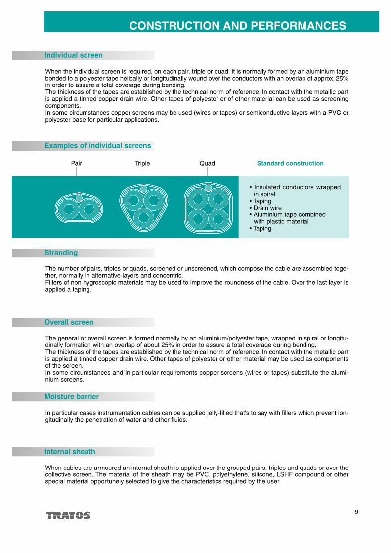
When the individual screen is required, on each pair, triple or quad, it is normally formed by an aluminium tapebonded to a polyester tape helically or longitudinally wound over the conductors with an overlap of approx. 25%in order to assure a total coverage during bending.The thickness of the tapes are established by the technical norm of reference. In contact with the metallic partis applied a tinned copper drain wire. Other tapes of polyester or of other material can be used as screeningcomponents.In some circumstances copper screens may be used (wires or tapes) or semiconductive layers with a PVC orpolyester base for particular applications.
The number of pairs, triples or quads, screened or unscreened, which compose the cable are assembled toge-ther, normally in alternative layers and concentric.Fillers of non hygroscopic materials may be used to improve the roundness of the cable. Over the last layer isapplied a taping.
Individual screen
Examples of individual screens
Stranding
The general or overall screen is formed normally by an aluminium/polyester tape, wrapped in spiral or longitu-dinally formation with an overlap of about 25% in order to assure a total coverage during bending.The thickness of the tapes are established by the technical norm of reference. In contact with the metallic partis applied a tinned copper drain wire. Other tapes of polyester or other material may be used as componentsof the screen.In some circumstances and in particular requirements copper screens (wires or tapes) substitute the alumi-nium screens.
Overall screen
In particular cases instrumentation cables can be supplied jelly-filled that's to say with fillers which prevent lon-gitudinally the penetration of water and other fluids.
Moisture barrier
When cables are armoured an internal sheath is applied over the grouped pairs, triples and quads or over thecollective screen. The material of the sheath may be PVC, polyethylene, silicone, LSHF compound or otherspecial material opportunely selected to give the characteristics required by the user.
Internal sheath
• Insulated conductors wrappedin spiral
• Taping• Drain wire• Aluminium tape combined
with plastic material• Taping
Pair Triple Quad Standard construction
Cavi non armati e senza guaina metallica 7,5 x diametro esterno
Cavi armati 10 x diametro esterno
C avi con guaina metallica 15 x diametro esterno
10
La protezione meccanica è assicurata tramite l'armatura metallica costituita da fili di acciaio zincato, applicatia treccia o su un singolo strato, nastri o piattine di acciaio zincato. L'armatura è anche una buona protezionecontro i roditori.
Armatura
La guaina esterna è costituita da un materiale scelto per soddisfare principalmente le condizioni di installazio-ne richieste.I materiali usati più comunemente sono PVC e polietilene ma altri possono essere usati come silicone o LSHFcompound.Speciali materiali possono essere utilizzati per applicazioni particolari e per conferire al cavo caratteristichecome la non propagazione dell'incendio, la resistenza agli idrocarburi, agli oli, solventi e altre sostanze chimi-che. Come massima sicurezza alle aggressioni chimiche si possono applicare guaine di piombo.Inoltre la bassa emissione di fumi, gas tossici e corrosivi in caso di combustione è ottenuta con l'impiego dimateriale per guaina appositamente messi a punto per questo scopo.Il colore della guaina esterna, per alcuni materiali, può subire variazioni se esposti alle radiazioni solari perlungo tempo. Variazioni che non comportano nessun effetto sulle prestazioni del cavo.
Guaina esterna
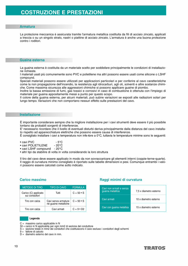
È importante considerare sempre che la migliore installazione per i cavi strumenti deve essere il più possibilelontano da probabili sorgenti di interferenze.E' necessario ricordare che il livello di eventuali disturbi deriva principalmente dalla distanza del cavo installa-to rispetto ad apparecchiature elettriche che possono essere causa di interferenze.È consigliato installare i cavi a tempera t u ra non infe riore a 0°C, tuttavia le temperature minime sono le seguenti:
• cavi PVC - 5°C• cavi POLIETILENE - 20°C• cavi LSHF compound - 20°C• altri tipi da stabilire di volta in volta considerando la loro struttura
Il tiro del cavo deve essere applicato in modo da non sovraccaricare gli elementi interni (coppie-terne-quarte).Il raggio di curvatura minimo consigliato è riportato sulle tabelle dimensioni e pesi. Comunque entrambi i valo-ri possono essere calcolati come sotto indicato.
METODO DI TIRO
Carico (C) applicato sui conduttori
Tiro con calza
Tiro con calza
TIPO Dl CAVO
Tutti
Cavi senza armaturené guaine metalliche
Cavi armati
FORMULA
C = 50 • S
C = 50 • S
C = 9 • D2
Installazione
Carico massimo
COSTRUZIONE E PRESTAZIONI
Raggi minimi di curvatura
C = massimo carico applicabile in N50 = carico in N applicabile per ogni mm2 di sezione del conduttoreS = sezione totale in mm2 dei conduttori che costituiscono il cavo escluso i conduttori degli schermi9 = fattore di calcoloD = diametro esterno del cavo in mm.
Legenda
11
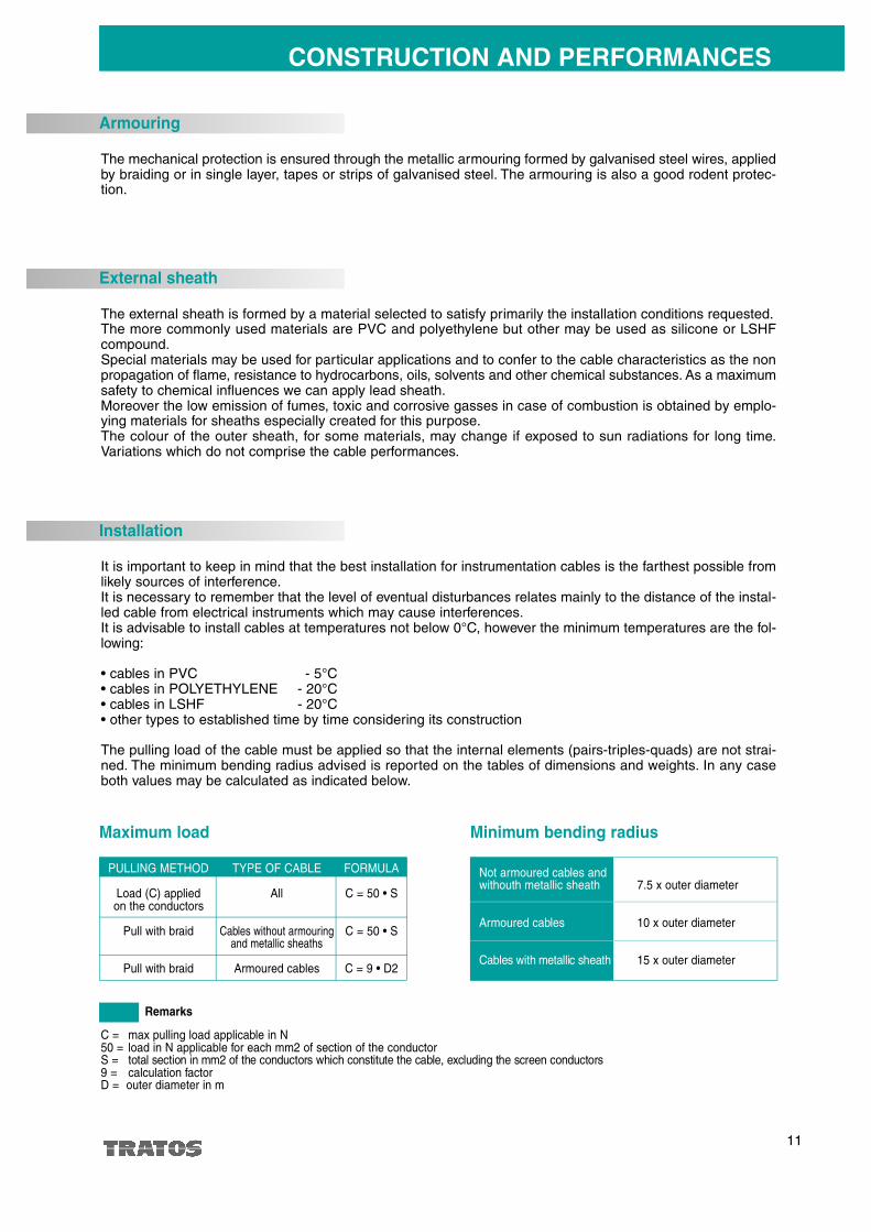
The mechanical protection is ensured through the metallic armouring formed by galvanised steel wires, appliedby braiding or in single layer, tapes or strips of galvanised steel. The armouring is also a good rodent protec-tion.
Armouring
The external sheath is formed by a material selected to satisfy primarily the installation conditions requested.The more commonly used materials are PVC and polyethylene but other may be used as silicone or LSHFcompound.Special materials may be used for particular applications and to confer to the cable characteristics as the nonpropagation of flame, resistance to hydrocarbons, oils, solvents and other chemical substances. As a maximumsafety to chemical influences we can apply lead sheath.Moreover the low emission of fumes, toxic and corrosive gasses in case of combustion is obtained by emplo-ying materials for sheaths especially created for this purpose.The colour of the outer sheath, for some materials, may change if exposed to sun radiations for long time.Variations which do not comprise the cable performances.
External sheath
It is important to keep in mind that the best installation for instrumentation cables is the farthest possible fromlikely sources of interference.It is necessary to remember that the level of eventual disturbances relates mainly to the distance of the instal-led cable from electrical instruments which may cause interferences.It is advisable to install cables at temperatures not below 0°C, however the minimum temperatures are the fol-lowing:
• cables in PVC - 5°C• cables in POLYETHYLENE - 20°C• cables in LSHF - 20°C• other types to established time by time considering its construction
The pulling load of the cable must be applied so that the internal elements (pairs-triples-quads) are not strai-ned. The minimum bending radius advised is reported on the tables of dimensions and weights. In any caseboth values may be calculated as indicated below.
PULLING METHOD
Load (C) applied on the conductors
Pull with braid
Pull with braid
TYPE OF CABLE
All
Cables without armouringand metallic sheaths
Armoured cables
FORMULA
C = 50 • S
C = 50 • S
C = 9 • D2
Installation
Maximum load
Not armoured cables and withouth metallic sheath 7.5 x outer diameter
Armoured cables 10 x outer diameter
C a bles with metallic sheath 15 x outer diameter
Minimum bending radius
C = max pulling load applicable in N50 = load in N applicable for each mm2 of section of the conductorS = total section in mm2 of the conductors which constitute the cabl e, excluding the screen conductors9 = calculation factorD = outer diameter in m
Remarks
CONSTRUCTION AND PERFORMANCES

R è dato dal rapporto fra la resistività del materale costituente il conduttore e la sezione.Varia in funzio-ne della temperatura.La resistenza elettrica del conduttore e molto importante per definire la capacità di trasmissione delsegnale.Si esprime in Ohm/Km.
Proprietà di un materiale isolante di mantenere la carica elettrica in una situazione di differenza di poten-ziale fra due conduttori.È consigliabile in linea di massima impiegare cavi con bassa capacità che consentono una lunghezzadi installazione maggiore.Si esprime in Farad/Km
I conduttori percorsi da correnti uguali e contra rie danno origine ad un campo magnetico.L'induttanza e il ra p p o rto tra il flusso che attraversa lo spazio tra due conduttori e la corrente che lo genera .Si esprime in Henry/Km
Le qualità trasmissive dei cavi strumentazione dipendono in gran parte dai seguenti parametri:
Resistenza elettrica del conduttore
Capacità mutua
Induttanza
12
DOVE IMPIEGARE I CAVI PER STRUMENTAZIONE
In tutti i casi dove c'è la necessità di trasportare segnali tra varie componenti di un sistema l'utilizzazione deicavi per strumenti è inevitabile perché la loro struttura è adatta a proteggere il segnale trasmesso da interfe-renze e disturbi interni ed esterni.Principalmente nel controllo dei processi industriali, impianti chimici e petroliferi, centrali elettriche.Tutti i cavi sono adatti per essere installati in aree a sicurezza intrinseca (AD-I) e antideflagranti (AD-PE) nelrispetto delle prescrizioni delle norme degli impianti in cui sono utilizzati.Il raggiungimento dell'obiettivo finale stabilito in un processo di controllo dipende molto dalla corretta scelta deicavi di interconnessione. La grande quantità di apparecchiature usate, la loro particolare sensibilità, la semprepiù ristretta tolleranza impongono di individuare il giusto cavo per ogni applicazione, ciò è possibile attingendodalla vasta gamma di prodotti che TRATOS CAVI mette a disposizione. E' auspicabile che qualsiasi problema-tica sia posta al nostro personale che la esaminerà tenendo in considerazione l'aspetto tecnico ed economico
Impiego
Caratteristiche trasmissive
R
C
L
R
C
L

R is the result of the radio between the material resistivity which forms the conductor and the secton.It varies according to the temperature.The electrical resistance of the conductor is very important in order to determine the transmission capa-citance of the signal.It is expressed in Ohm/Km.
Property of an insulation material to keep the electrical charge in a situation of potential difference bet-ween two conductors.It is recommended as a rule to employ cables with low capacitance which allow a longer length of instal-lation.It is expressed in Farad/Km.
The conductors running with equal and opposite currents give rise to a magnetic field.Inductance is the ratio between the flow which pass through the space of two conductors and the currentwhich produce it.It is expressed in Henry / K m .
13
WHERE TO EMPLOY CABLES FOR INSTRUMENTATION
In all cases where there is a necessity to carry signals between various components of a system, the use ofinstrumentation cables is inevitable because their structure is suitable to protect the transmitted signal frominternal and external interferences and disturbances.Principally in the control of industrial processes, chemical and petroleum plants, electrical power plants.All the cables are suitable for installation in areas of intrinsic security (AD-I) and antideflagrating (AD-PE) inrespect of the prescribed norms of the plants where they are being utilised.The attainment of the ultimate goal established in a control process depends a lot on the correct selection ofthe interconnecting cables. The large quantity of the instruments used, their particular sensibility, the evermo-re restricted tolerances imposes the identification of the right cable for each application, this is made possibleby selection from the vast range of products which TRATOS CAVI makes available. It is desirable that any pro-blem be presented to our personnel which will examine it thoroughly keeping in consideration the technical andeconomical aspect for the best solution.
Employ
R
C
L
The transmission performances of instrumentation cables depend largely on the following parameters:
Electrical resistance of the conductor
Mutual capacitance
Inductance
Transmission characteristics
R
C
L
14
INTERFERENZE
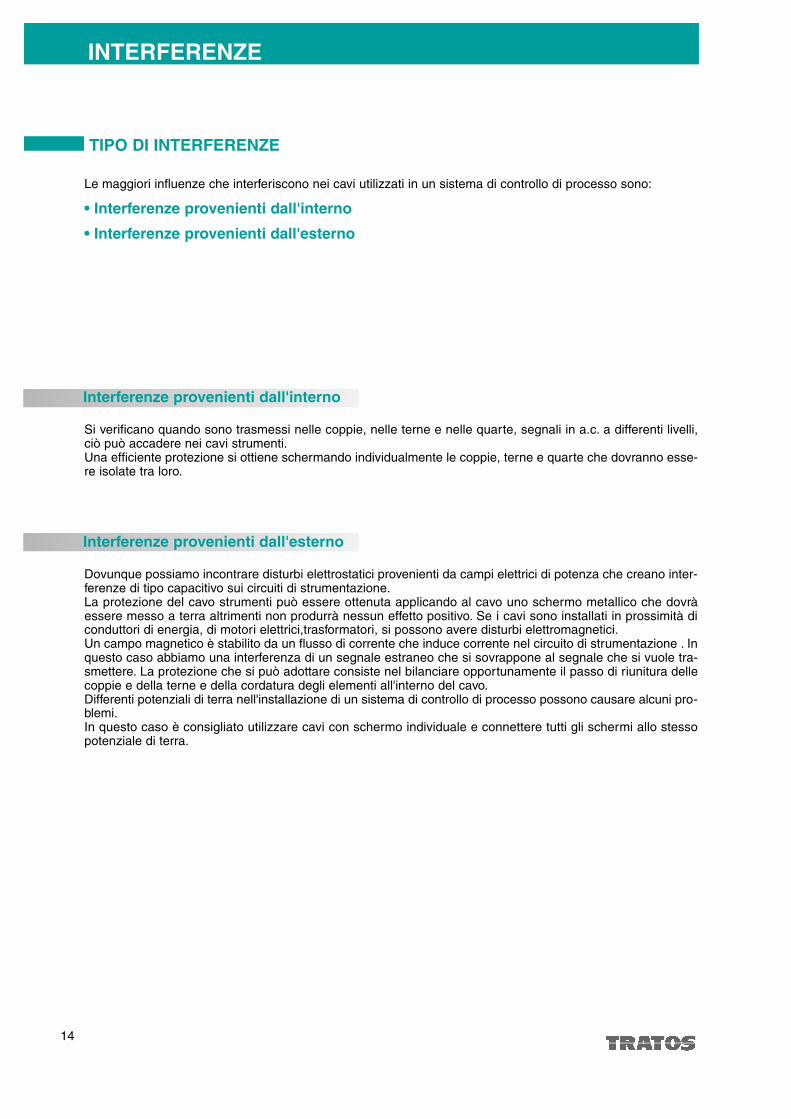
Si verificano quando sono trasmessi nelle coppie, nelle terne e nelle quarte, segnali in a.c. a differenti livelli,ciò può accadere nei cavi strumenti.Una efficiente protezione si ottiene schermando individualmente le coppie, terne e quarte che dovranno esse-re isolate tra loro.
Le maggiori influenze che interferiscono nei cavi utilizzati in un sistema di controllo di processo sono:
• Interferenze provenienti dall'interno
• Interferenze provenienti dall'esterno
Interferenze provenienti dall'interno
Dovunque possiamo incontrare disturbi elettrostatici provenienti da campi elettrici di potenza che creano inter-ferenze di tipo capacitivo sui circuiti di strumentazione.La protezione del cavo strumenti può essere ottenuta applicando al cavo uno schermo metallico che dovràessere messo a terra altrimenti non produrrà nessun effetto positivo. Se i cavi sono installati in prossimità diconduttori di energia, di motori elettrici,trasformatori, si possono avere disturbi elettromagnetici.Un campo magnetico è stabilito da un flusso di corrente che induce corrente nel circuito di strumentazione . Inquesto caso abbiamo una interferenza di un segnale estraneo che si sovrappone al segnale che si vuole tra-smettere. La protezione che si può adottare consiste nel bilanciare opportunamente il passo di riunitura dellecoppie e della terne e della cordatura degli elementi all'interno del cavo.Differenti potenziali di terra nell'installazione di un sistema di controllo di processo possono causare alcuni pro-blemi.In questo caso è consigliato utilizzare cavi con schermo individuale e connettere tutti gli schermi allo stessopotenziale di terra.
Interferenze provenienti dall'esterno
TIPO DI INTERFERENZE

15
INFLUENCES
These appear when signals in alternating current are transmitted in the pairs, triples and quads, at differentlevels, this may happen in cables for instrumentation..An efficient protection is obtained by individual screening the pairs, triples and quads which must be isolatedbetween themselves.
The major influences which interfere in cables used in a system for process control are:
• Influences from internal sources
• Influences from external sources
Influences from internal sources
Anywhere we can encounter electrostatic disturbances coming from electrical power fields which create capa-citive interferences on instrumentation circuits.The protection of the instrumentation cable can be obtained applying on the cable a metallic screen which haveto be connected to earth otherwise it will not produce a positive effect.If the cables are installed in proximity of power conductors, of electrical motors, transformers, we can have elec-tromagnetic disturbances.A magnetic field is established by a flow of current which induces current into the instrumentation circuit. In thiscase we have an interference of a foreign signal which overlays the signal which we want to transmit. The pro-tection which can be adopted consists in coordinating appropriately the lay length of the pairs and of the triplesand by gathering the elements inside the cable.Different potentials to ground during installation of a process control system can cause some problems.In this case it is advisable to use cables with individual screen and connect all the screens to the same groun-ding potential.
Influences from external sources
INFLUENCES TYPE

16
SCELTA DELLO SCHERMO CON RIFERIMENTO AL TIPO DI INTERFERENZA
Correnti di flusso derivanti da differenti potenziali di terra.
S c h e rmi individuali sulle coppie,terne o quarte in alluminio o rame.
Altre influenze
Causa Soluzione
Causa Soluzione
Corretta scelta del passo di cordatura degli elementi.
Dal flusso di corrente trasportata dagrossi conduttori , m o t o ri elettri c i ,trasformatori, elementi.
Disturbi elettromagnetici
Accoppiamento capacitivo con uncampo elettrico emanato da unasorgente di energia.
S c h e rmo comune in alluminio orame.
Disturbi elettrostatici
Causa Soluzione
Differenti livelli di energia all’internodel cavo.
Schermo individuale delle coppie odelle terne. Lo schermo può esserein alluminio o rame.
Influenze esterne
Causa Soluzione
17
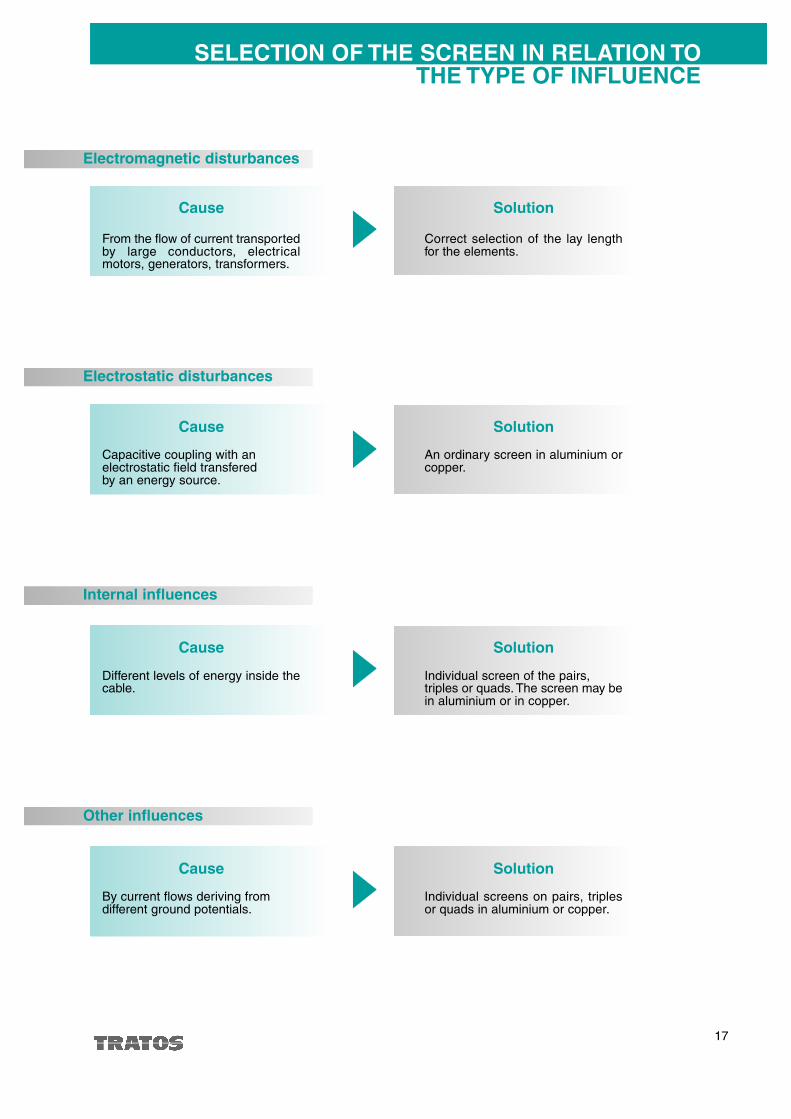
SELECTION OF THE SCREEN IN RELATION TOTHE TYPE OF INFLUENCE
By current flows deriving from different ground potentials.
Individual screens on pairs, triplesor quads in aluminium or copper.
Other influences
Cause Solution
Cause Solution
Correct selection of the lay lengthfor the elements.
From the flow of current transportedby large conductors, electri c a lmotors, generators, transformers.
Electromagnetic disturbances
Capacitive coupling with anelectrostatic field transfered by an energy source.
An ordinary screen in aluminium orcopper.
Electrostatic disturbances
Cause Solution
Different levels of energy inside thecable.
Individual screen of the pairs,triples or quads. The screen may bein aluminium or in copper.
Internal influences
Cause Solution
18
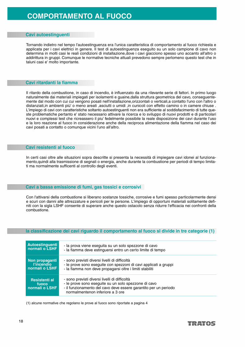
COMPORTAMENTO AL FUOCO
Tornando indietro nel tempo l'autoestinguenza era l'unica caratteristica di comportamento al fuoco richiesta eapplicata per i cavi elettrici in genere. Il test di autoestinguenza eseguito su un solo campione di cavo nondetermina in molti casi le reali condizioni di installazione,dove i cavi giacciono spesso uno accanto all'altro oaddirittura in gruppi. Comunque le normative tecniche attuali prevedono sempre perlomeno questo test che intaluni casi e' molto importante.
Cavi autoestinguenti
Il ritardo della combustione, in caso di incendio, è influenzato da una rilevante serie di fattori. In primo luogonaturalmente dai materiali impiegati per isolamenti e guaine,dalla struttura geometrica del cavo, conseguente-mente dal modo con cui cui vengono posati nell'installazione,orizzontali o verticali,a contatto l'uno con l'altro odistanziati,in ambienti più' o meno areati ,asciutti o umidi ,in cunicoli con effetto camino o in camere chiuse .L'impiego di cavi con caratteristiche soltanto autoestinguenti non era sufficiente al soddisfacimento di tutte que-ste problematiche pertanto e' stato necessario attivare la ricerca e lo sviluppo di nuovi prodotti e di particolarinuovi e complessi test che ricreassero il piu' fedelmente possibile la reale disposizione dei cavi durante l'usoe la loro reazione al fuoco in considerazione anche della reciproca alimentazione della fiamma nel caso deicavi posati a contatto o comunque vicini l'uno all'altro.
Cavi ritardanti la fiamma
In certi casi oltre alle situazioni sopra descritte si presenta la necessità di impiegare cavi idonei al funziona-mento,quindi alla trasmissione di segnali o energia, anche durante la combustione per periodi di tempo limita-ti ma normalmente sufficenti al controllo degli eventi.
Cavi resistenti al fuoco
Con l'attivarsi della combustione si liberano sostanze tossiche, corrosive e fumi spesso particolarmente densie scuri con danni alle attrezzature e pericoli per le persone. L'impiego di opportuni materiali solitamente defi-niti con la sigla LSHF consente di superare anche questo ostacolo senza ridurre l'efficacia nei confronti dellacombustione.
(1) alcune normative che regolano le prove al fuoco sono riportate a pagina 4
Cavi a bassa emissione di fumi, gas tossici e corrosivi
la classificazione dei cavi riguardo il comportamento al fuoco sl divide in tre categorie (1)
Autoestinguenti normali o LSHF
Non propagantil’incendio
normali o LSHF
Resistenti alfuoco
normali o LSHF
- la prova viene eseguita su un solo spezzone di cavo- la fiamma deve estinguersi entro un certo limite di tempo
- sono previsti diversi livelli di difficoltà- le prove sono eseguite con spezzoni di cavi applicati a gruppi- la fiamma non deve propagarsi oltre i limiti stabiliti
- sono previsti diversi livelli di difficoltà- le prove sono eseguite su un solo spezzone di cavo- il funzionamento del cavo deve essere garantito per un periodonormalmentenon inferiore a 3 ore

19
BEHAVIOUR TO FIRE CONDITIONS
In the past self-extinguishing was the only required characteristic of behaviour in fire conditions and applied forelectrical cables in general. The self-extinguish test carried out in only one sample of cable, does not determi-ne in all cases the real installation conditions, where the cables often lie one near to the other or in groups. Inany case the current technical standards require always this test which in some cases is very important.
Self-extinguish cables
The delay of combustion, in case of fire, is influenced by many factors. First of all on the types of material usedfor insulation and sheath, on the geometrical structure of the cable, consequently the way the cables are laidduring installation, horizontally or vertically, one near to the other or separated, in areas with or without air, dryor damp, in ducts with chimney effects or in closed rooms.The employ of cables with only self-extinguish characteristics was not adequately to solve all these problems,therefore it has been necessary to extend the research and the development of new products and new speci-fic and elaborate tests able to recreate as accurately as possible the real disposition of the cables during theiremployment and their behaviour to fire conditions considering also the mutual combustion of flame in case thecables are lied in contact or however one near to the other.
Flame retardant cables
Besides the above described conditions in some cases is required to employ cables suitable for operating, thusfor signalling and power transmission, also during combustion for a limited period of time but normally enoughto control the events.
Fire resisting cables
When combustion occurs toxic and corrosive substances, particular dark and dense fumes are released andmay cause damages to equipment and dangerous for people.The employ of appropriate materials, usually called LSHF, enable also to overcome this difficulty without redu-cing the effect towards combustion.
(1) some standards which call the fire tests are reported at page 5
Cables with low emission of fumes, toxic and corrosive gasses
The classification of cables regarding behaviour on fire conditions is divided in three levels (1)
Self-extinguish normal or LSHF
Non propagatingthe flame
normal or LSHF
Fire resistingnormal or LSHF
- the test is carried out in only one piece of cable - the flame must extinguish within a limit time
- there are different levels of difficulty- the tests are carried out on pieces of cables applied in groups- the flame must extinguish over the limits fixed
- there are different levels of difficulty - the tests are carried out on only one piece of cable - the good functioning of the cable must be warranted for a
period which is normally not less than 3 hours.

20
Alcuni esempi di cavi strumentazioneFew examples of instrumentation cables
1
2
3
4
5
6
cavo multicoppia, conduttori flessibili di rame classe 5, schermo individuale e globale in alluminio,guainainterna, armatura a nastri di acciaio zincato ( tipo 2).guaina esterna
multicore cable, flexible copper conductors class 5, individual and overall screen in aluminium, innersheath, galvanized steel tape armouring (type 2), outer sheath.
cavo singola coppia,conduttori flessibili di rame stagnato classe 5, schermi in alluminio,guainainterna,armatura a treccia di fili di acciaio zincato (tipo 1),guaina esterna
single pair cable, flexible tinned copper conductors class 5, aluminium screens, inner sheath, galvanizedsteel wire braid armouring (type 1), outer sheath
cavo a due coppie (una quarta) conduttori flessibili di rame classe 5, nastratura sui conduttori isolati(separatore), armatura a nastro longitudinale di alluminio termosaldato ( tipo 7), guaina esterna
two-pair cable (1 quad), flexible copper conductors class 5, taping on the insulated conductors(separator) thermo-welded aluminium longitudinal tape armouring (type 7), outer sheath
cavo multicoppia, conduttori di rame stagnato classe 2, schermo globale in alluminio, guaina esterna
multicore cable, tinned copper conductors class 2, overall aluminium screen, outer sheath
cavo multicoppia, conduttori flessibili di rame classe 5, schermo individuale e globale ,guaina esterna
multicore cable, flexible copper conductors class 5, individual and overall screen, outer sheath
cavo multicoppia, conduttori flessibili di rame classe 5, schermo individuale e globale in alluminio, guainainterna, armatura a nastro corrugato di acciaio ( tipo 6), guaina esterna
multicore cable, flexible copper conductors class 5, individual and overall aluminium screen, inner sheathcorrugated steel tape armouring (type 6), outer sheath

21
Alcuni esempi di cavi strumentazioneFew examples of instrumentation cables
7
8
9
10
11
12cavo ad una coppia piu conduttore di terra, conduttori flessibili di rame classe 5, schermo in alluminio(conduttore di terra collocato all'esterno dello schermo), guaina esterna
one-pair cable plus earth conductor, flexible copper conductors class 5, aluminium screen (earthconductor situated outside the screen), outer sheath
cavo ad una terna, conduttori flessibili di rame classe 5, schermo in alluminio, guaina interna, armaturaa fili di acciaio zincato (tipo 5), guaina esterna
three-core cable, flexible copper conductors class 5, aluminium screen, inner sheath, galvanized steelwire armouring (type 5), outer sheath
cavo ad una coppia, conduttori flessibili di rame classe 5, schermo in alluminio, guaina interna, armaturaa fili e nastro contro spirale di acciaio zincato (tipo 3), guaina esterna
one pair cable, flexible copper conductors class 5, aluminium screen, inner sheath, wire armouring andgalvanized steel tape with reciprocating lay (type 3), outer sheath
cavo ad una coppia per collegamento termocoppie, conduttori rigidi classe 1, schermo in alluminioguaina interna, armatura a treccia di fili di acciaio zincato (tipo 1 ), guaina esterna
one pair cable for thermocouple connection, solid conductors class 1, aluminium screen, inner sheath,galvanized steel wire braid armouring (type 1), outer sheath
cavo multicoppia per collegamento termocoppie, conduttori rigidi classe 1, schermo singolo e globale inalluminio guaina interna, armatura a piattine e nastro controspirale di acciaio zincato ( tipo 4), guainaesterna
multicore cable for thermocouple connection, solid conductors class 1, individual and ove rall aluminiumscreen, inner sheath, flat arm o u ring and galva n i zed steel tape with reciprocating lay (type 4), outer sheath.
cavo a due coppie separate, conduttori flessibili di rame classe 5, schermo globale, prima guainainterna, conduttori nudi di terra, seconda guaina interna, armatura a fili e nastro controspirale di acciaiozincato (tipo 3), guaina estrerna
cable with two separate pairs, flexible copper conductors class 5, overall screen, first inner sheath, earthconductors, second inner sheath, wire armouring and galvanized steel tape with reciprocating lay (type3), outer sheath

22
Nastro di alluminio(Copertura 100%)Costo contenuto
Alluminium tape(Coperture 100%)Moderate cost
Treccia di fili di rame(copertura 75% circa)Alto costo
Copper wire braid(coperture 75% approx)High cost
Treccia di fili di rame(copertura 90% circa)Alto costo
Copper wire braid(coperture 90% approx)High cost
Nastri di rame(copertura 100%)Alto costo
Copper tapes(coperture 100%)High cost
Nastri di rame(copertura 100%)Alto costo
Copper tapes(coperture 100%)High cost
alto valore di resistenza elettrica c.c.
high value of electrical resistance c.c.
basso valore di resistenza elettrica c.c.
low value of electrical resistance c.c.
basso valore di resistenza elettrica c.c.
low value of electrical resistance c.c.
basso valore di resistenzaelettrica cc. unito ad un altovalore di induttanza
low dc value of electricalresistance together with highinductance
bassissimo valore diresistenza elettrica c.c.altissimo valore di induttanza
very low value of electricalresistance c.c.very high inductance value
MODERATO
MODERATE
DISCRETO
QUITE GOOD
BUONO
GOOD
OTTIMO
VERY GOOD
ECCEZIONALE
EXCEPTIONAL
cavi armatiin acciaio
steel armouredcables
cavi armaticon materiali magnetici dolci
armoured cableswith soft magneticmaterials
SchermatureScreening
Effetto schermanteScreen capacity
Tipo di schermo
Type of screen
Caratteristiche dello schermo
Screen characteristics
Fattore di riduzione
Reduction factor
Il fattore di riduzione è il rapporto tra la tensione interferente indotta sul cavo in presenza della schermatura ela stessa tensione indotta sul cavo senza schermatura.
The reduction factor is the radio between the interference tension induced in a screened cable and the sametension induced in a not screened cable.
23
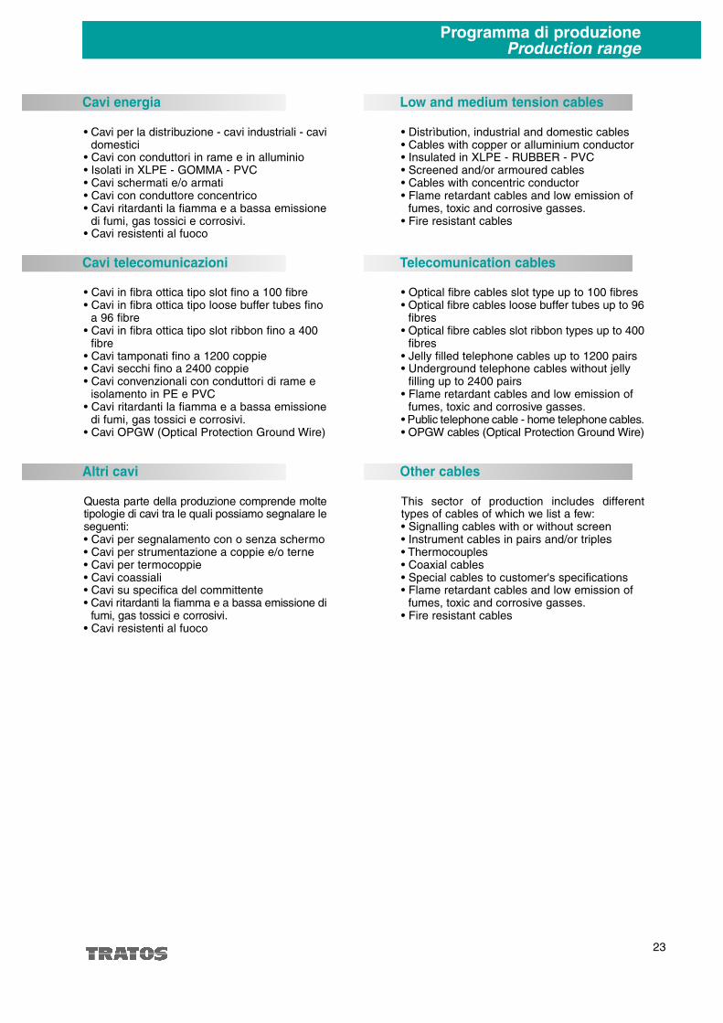
Programma di produzioneProduction range
• Cavi per la distribuzione - cavi industriali - cavidomestici
• Cavi con conduttori in rame e in alluminio• Isolati in XLPE - GOMMA - PVC• Cavi schermati e/o armati• Cavi con conduttore concentrico• Cavi ritardanti la fiamma e a bassa emissione
di fumi, gas tossici e corrosivi.• Cavi resistenti al fuoco
Cavi energia
• Cavi in fibra ottica tipo slot fino a 100 fibre• Cavi in fibra ottica tipo loose buffer tubes fino
a 96 fibre• Cavi in fibra ottica tipo slot ribbon fino a 400
fibre• Cavi tamponati fino a 1200 coppie• Cavi secchi fino a 2400 coppie• Cavi convenzionali con conduttori di rame e
isolamento in PE e PVC• Cavi ritardanti la fiamma e a bassa emissione
di fumi, gas tossici e corrosivi.• Cavi OPGW (Optical Protection Ground Wire)
Cavi telecomunicazioni
• Distrìbution, industrial and domestic cables• Cables with copper or alluminium conductor• Insulated in XLPE - RUBBER - PVC• Screened and/or armoured cables• Cables with concentric conductor • Flame retardant cables and low emission of
fumes, toxic and corrosive gasses.• Fire resistant cables
Low and medium tension cables
• Optical fibre cables slot type up to 100 fibres• Optical fibre cables loose buffer tubes up to 96
fibres• Optical fibre cables slot ribbon types up to 400
fibres• Jelly filled telephone cables up to 1200 pairs• Underground telephone cables without jelly
filling up to 2400 pairs• Flame retardant cables and low emission of
fumes, toxic and corrosive gasses.• Public telephone cable - home telephone cabl e s.• OPGW cables (Optical Protection Ground W i r e )
Telecomunication cables
Questa parte della produzione comprende moltetipologie di cavi tra le quali possiamo segnalare les e g u e n t i :• Cavi per segnalamento con o senza schermo• Cavi per strumentazione a coppie e/o terne• Cavi per termocoppie• Cavi coassiali• Cavi su specifica del committente• C avi ritardanti la fiamma e a bassa emissione di
fumi, gas tossici e corrosivi.• Cavi resistenti al fuoco
Altri cavi
This sector of production includes diffe r e n ttypes of cables of which we list a few:• Signalling cables with or without screen• Instrument cables in pairs and/or triples• Thermocouples• Coaxial cables• Special cables to customer's specifications• Flame retardant cables and low emission of
fumes, toxic and corrosive gasses.• Fire resistant cables
Other cables

24
DimensioniDimensions
Normative inglesiBritish standard
BS 5308 Part.1 Table 6 FEXOHR-300/300 V
Capacitàmutua
pF/mt max.
Max. Mutualcapacitance
pF/mt.
115
75
75
75
75
75
75
75
Resistenza delconduttore a
20°C�/Km max.
Maxconductor
resistance at20° �/Km
39.7
39.7
39.7
39.7
39.7
39.7
39.7
39.7
Numerocoppie
Numberof pairs
1
2(*)
5
10
15
20
30
50
Sezionemm2
Sectionmm2
0.5
0.5
0.5
0.5
0.5
0.5
0.5
0.5
Spessoreisolante
nominalemm
Nominalinsulationthickness
mm
0.6
0.6
0.6
0.6
0.6
0.6
0.6
0.6
Diametroesterno
nominalemm
Nominal outerdiameter
mm
6.7
7.6
12.5
17.0
20.0
22.2
26.5
33.5
Pesoindicativodel cavoKg/mt
Approx. cableweightKm/mt.
0.064
0.076
0.164
0.270
0.386
0.483
0.691
1.053
Capacitàmutua
pF/mt max.
Max. Mutualcapacitance
pF/mt.
115
75
75
75
75
75
75
75
Resistenza delconduttore a
20°C�/Km max.
Maxconductor
resistance at20° �/Km
39.7
39.7
39.7
39.7
39.7
39.7
39.7
39.7
BS 5308 Part.1 Table 6 FEXOHRFR-300/300 V
Numerocoppie
Numberof pairs
1
2(*)
5
10
15
20
30
50
Sezionemm2
Sectionmm2
0.5
0.5
0.5
0.5
0.5
0.5
0.5
0.5
Spessoreisolante
nominalemm
Nominalinsulationthickness
mm
0.6
0.6
0.6
0.6
0.6
0.6
0.6
0.6
Diametroesterno
nominalemm
Nominal outerdiameter
mm
11.4
12.3
17.6
23.0
26.9
29.3
33.8
42.0
Pesoindicativodel cavoKg/mt
Approx. cableweightKm/mt.
0.249
0.281
0.503
0.846
1.210
1.401
1.802
2.728
(*) 1 quarta / 1 quad
(*) 1 quarta / 1 quad

25
DimensioniDimensions
Normative inglesiBritish standard
Capacitàmutua
pF/mt max.
Max. Mutualcapacitance
pF/mt.
115
75
75
75
75
75
75
75
Resistenza delconduttore a
20°C�/Km max.
Maxconductor
resistance at20° �/Km
39.7
39.7
39.7
39.7
39.7
39.7
39.7
39.7
BS 5308 Part.1 Table 6 FEXOHRLRFR-300/300 V
Numerocoppie
Numberof pairs
1
2(*)
5
10
15
20
30
50
Sezionemm2
Sectionmm2
0.5
0.5
0.5
0.5
0.5
0.5
0.5
0.5
Spessoreisolante
nominalemm
Nominalinsulationthickness
mm
0.6
0.6
0.6
0.6
0.6
0.6
0.6
0.6
Diametroesterno
nominalemm
Nominal outerdiameter
mm
15.8
16.7
22.0
28.2
32.1
34.5
40.8
50.0
Pesoindicativodel cavoKg/mt
Approx. cableweightKm/mt.
0.740
0.800
1.278
1.990
2.619
2.939
4.535
5.370
Capacitàmutua
pF/mt max.
Max. Mutualcapacitance
pF/mt.
115
115
115
115
115
115
155
Resistenza delconduttore a
20°C�/Km max.
Maxconductor
resistance at20° �/Km
39.7
39.7
39.7
39.7
39.7
39.7
39.7
BS 5308 Part.1 Table 7 FEXHOHR-300/300 V
Numerocoppie
Numberof pairs
2
5
10
15
20
30
50
Sezionemm2
Sectionmm2
0.5
0.5
0.5
0.5
0.5
0.5
0.5
Spessoreisolante
nominalemm
Nominalinsulationthickness
mm
0.6
0.6
0.6
0.6
0.6
0.6
0.6
Diametroesterno
nominalemm
Nominal outerdiameter
mm
10.5
13.9
19.2
22.4
24.8
29.6
38.5
Pesoindicativodel cavoKg/mt
Approx. cableweightKm/mt.
0.142
0.233
0.410
0.584
0.732
1.054
1.732
(*) 1 quarta / 1 quad

26
DimensioniDimensions
Normative inglesiBritish standard
Capacitàmutua
pF/mt max.
Max. Mutualcapacitance
pF/mt.
115
115
115
115
115
115
115
Resistenza delconduttore a
20°C�/Km max.
Maxconductor
resistance at20° �/Km
39.7
39.7
39.7
39.7
39.7
39.7
39.7
BS 5308 Part.1 Table 7 FEXHOHRFR-300/300 V
Numerocoppie
Numberof pairs
2
5
10
15
20
30
50
Sezionemm2
Sectionmm2
0.5
0.5
0.5
0.5
0.5
0.5
0.5
Spessoreisolante
nominalemm
Nominalinsulationthickness
mm
0.6
0.6
0.6
0.6
0.6
0.6
0.6
Diametroesterno
nominalemm
Nominal outerdiameter
mm
15.6
19.9
26.3
29.5
32.9
38.2
48.7
Pesoindicativodel cavoKg/mt
Approx. cableweightKm/mt.
0.430
0.710
1.208
1.503
1.774
2.554
4.102
Capacitàmutua
pF/mt max.
Max. Mutualcapacitance
pF/mt.
115
115
115
115
115
115
115
Resistenza delconduttore a
20°C�/Km max.
Maxconductor
resistance at20° �/Km
39.7
39.7
39.7
39.7
39.7
39.7
39.7
BS 5308 Part.1 Table 7 FEXHOHRLRFR-300/300 V
Numerocoppie
Numberof pairs
2
5
10
15
20
30
50
Sezionemm2
Sectionmm2
0.5
0.5
0.5
0.5
0.5
0.5
0.5
Spessoreisolante
nominalemm
Nominalinsulationthickness
mm
0.6
0.6
0.6
0.6
0.6
0.6
0.6
Diametroesterno
nominalemm
Nominal outerdiameter
mm
20.7
25.4
31.5
36.3
39.2
44.4
56.2
Pesoindicativodel cavoKg/mt
Approx. cableweightKm/mt.
1.209
1.742
2.579
3.421
3.985
4.975
7.805

27
DimensioniDimensions
Normative inglesiBritish standard
Capacitàmutua
pF/mt max.
Max. Mutualcapacitance
pF/mt.
115
85
85
85
85
85
85
85
Resistenza delconduttore a
20°C�/Km max.
Maxconductor
resistance at20° �/Km
12.3
12.3
12.3
12.3
12.3
12.3
12.3
12.3
BS 5308 Part.1 Table 6 FEXOHRLRFR-300/300 V
Numerocoppie
Numberof pairs
1
2(*)
5
10
15
20
30
50
Sezionemm2
Sectionmm2
0.5
0.5
0.5
0.5
0.5
0.5
0.5
0.5
Spessoreisolante
nominalemm
Nominalinsulationthickness
mm
0.6
0.6
0.6
0.6
0.6
0.6
0.6
0.6
Diametroesterno
nominalemm
Nominal outerdiameter
mm
8.1
9.5
16.3
22.8
26.6
29.5
35.3
47.5
Pesoindicativodel cavoKg/mt
Approx. cableweightKm/mt.
0.092
0.133
0.306
0.545
0.779
0.988
1.433
2.332
(*) 1 quarta / 1 quad
Capacitàmutua
pF/mt max.
Max. Mutualcapacitance
pF/mt.
115
85
85
85
85
85
85
85
Resistenza delconduttore a
20°C�/Km max.
Maxconductor
resistance at20° �/Km
12.3
12.3
12.3
12.3
12.3
12.3
12.3
12.3
BS 5308 Part.1 Table 8 REXOHRFR-300/300 V
Numerocoppie
Numberof pairs
1
2(*)
5
10
15
20
30
50
Sezionemm2
Sectionmm2
0.5
0.5
0.5
0.5
0.5
0.5
0.5
0.5
Spessoreisolante
nominalemm
Nominalinsulationthickness
mm
0.6
0.6
0.6
0.6
0.6
0.6
0.6
0.6
Diametroesterno
nominalemm
Nominal outerdiameter
mm
13.0
14.4
22.3
29.9
33.9
37.8
43.8
55.8
Pesoindicativodel cavoKg/mt
Approx. cableweightKm/mt.
0.317
0.392
0.858
1.485
1.892
2.459
3.200
5.118
(*) 1 quarta / 1 quad
28
DimensioniDimensions
Normative inglesiBritish standard
Capacitàmutua
pF/mt max.
Max. Mutualcapacitance
pF/mt.
115
85
85
85
85
85
85
85
Resistenza delconduttore a
20°C�/Km max.
Maxconductor
resistance at20° �/Km
12.3
12.3
12.3
12.3
12.3
12.3
12.3
12.3
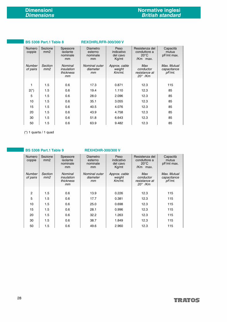
BS 5308 Part.1 Table 8 REXOHRLRFR-300/300 V
Numerocoppie
Numberof pairs
1
2(*)
5
10
15
20
30
50
Sezionemm2
Sectionmm2
1.5
1.5
1.5
1.5
1.5
1.5
1.5
1.5
Spessoreisolante
nominalemm
Nominalinsulationthickness
mm
0.6
0.6
0.6
0.6
0.6
0.6
0.6
0.6
Diametroesterno
nominalemm
Nominal outerdiameter
mm
17.3
19.4
28.0
35.1
40.5
43.9
51.8
63.9
Pesoindicativodel cavoKg/mt
Approx. cableweightKm/mt.
0.871
1.110
2.096
3.055
4.076
4.758
6.643
9.482
Capacitàmutua
pF/mt max.
Max. Mutualcapacitance
pF/mt.
115
115
115
115
115
115
115
Resistenza delconduttore a
20°C�/Km max.
Maxconductor
resistance at20° �/Km
12.3
12.3
12.3
12.3
12.3
12.3
12.3
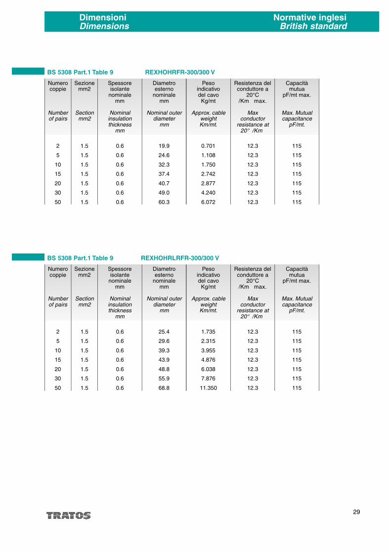
BS 5308 Part.1 Table 9 REXHOHR-300/300 V
Numerocoppie
Numberof pairs
2
5
10
15
20
30
50
Sezionemm2
Sectionmm2
1.5
1.5
1.5
1.5
1.5
1.5
1.5
Spessoreisolante
nominalemm
Nominalinsulationthickness
mm
0.6
0.6
0.6
0.6
0.6
0.6
0.6
Diametroesterno
nominalemm
Nominal outerdiameter
mm
13.9
17.7
25.0
28.1
32.2
38.7
49.6
Pesoindicativodel cavoKg/mt
Approx. cableweightKm/mt.
0.226
0.381
0.698
0.996
1.263
1.849
2.960
(*) 1 quarta / 1 quad
29
DimensioniDimensions
Normative inglesiBritish standard
Capacitàmutua
pF/mt max.
Max. Mutualcapacitance
pF/mt.
115
115
115
115
115
115
115
Resistenza delconduttore a
20°C�/Km max.
Maxconductor
resistance at20° �/Km
12.3
12.3
12.3
12.3
12.3
12.3
12.3
BS 5308 Part.1 Table 9 REXHOHRFR-300/300 V
Numerocoppie
Numberof pairs
2
5
10
15
20
30
50
Sezionemm2
Sectionmm2
1.5
1.5
1.5
1.5
1.5
1.5
1.5
Spessoreisolante
nominalemm
Nominalinsulationthickness
mm
0.6
0.6
0.6
0.6
0.6
0.6
0.6
Diametroesterno
nominalemm
Nominal outerdiameter
mm
19.9
24.6
32.3
37.4
40.7
49.0
60.3
Pesoindicativodel cavoKg/mt
Approx. cableweightKm/mt.
0.701
1.108
1.750
2.742
2.877
4.240
6.072
Capacitàmutua
pF/mt max.
Max. Mutualcapacitance
pF/mt.
115
115
115
115
115
115
115
Resistenza delconduttore a
20°C�/Km max.
Maxconductor
resistance at20° �/Km
12.3
12.3
12.3
12.3
12.3
12.3
12.3
BS 5308 Part.1 Table 9 REXHOHRLRFR-300/300 V
Numerocoppie
Numberof pairs
2
5
10
15
20
30
50
Sezionemm2
Sectionmm2
1.5
1.5
1.5
1.5
1.5
1.5
1.5
Spessoreisolante
nominalemm
Nominalinsulationthickness
mm
0.6
0.6
0.6
0.6
0.6
0.6
0.6
Diametroesterno
nominalemm
Nominal outerdiameter
mm
25.4
29.6
39.3
43.9
48.8
55.9
68.8
Pesoindicativodel cavoKg/mt
Approx. cableweightKm/mt.
1.735
2.315
3.955
4.876
6.038
7.876
11.350
30
DimensioniDimensions
Normative inglesiBritish standard
Capacitàmutua
pF/mt max.
Max. Mutualcapacitance
pF/mt.
250
250
250
250
250
250
250
250
Resistenza delconduttore a
20°C�/Km max.
Maxconductor
resistance at20° �/Km
39.7
39.7
39.7
39.7
39.7
39.7
39.7
39.7
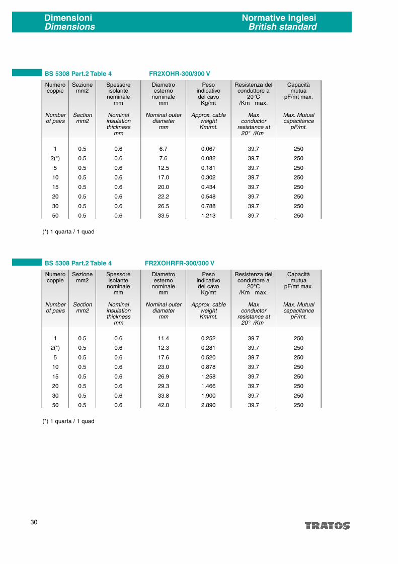
BS 5308 Part.2 Table 4 FR2XOHR-300/300 V
Numerocoppie
Numberof pairs
1
2(*)
5
10
15
20
30
50
Sezionemm2
Sectionmm2
0.5
0.5
0.5
0.5
0.5
0.5
0.5
0.5
Spessoreisolante
nominalemm
Nominalinsulationthickness
mm
0.6
0.6
0.6
0.6
0.6
0.6
0.6
0.6
Diametroesterno
nominalemm
Nominal outerdiameter
mm
6.7
7.6
12.5
17.0
20.0
22.2
26.5
33.5
Pesoindicativodel cavoKg/mt
Approx. cableweightKm/mt.
0.067
0.082
0.181
0.302
0.434
0.548
0.788
1.213
Capacitàmutua
pF/mt max.
Max. Mutualcapacitance
pF/mt.
250
250
250
250
250
250
250
250
Resistenza delconduttore a
20°C�/Km max.
Maxconductor
resistance at20° �/Km
39.7
39.7
39.7
39.7
39.7
39.7
39.7
39.7
BS 5308 Part.2 Table 4 FR2XOHRFR-300/300 V
Numerocoppie
Numberof pairs
1
2(*)
5
10
15
20
30
50
Sezionemm2
Sectionmm2
0.5
0.5
0.5
0.5
0.5
0.5
0.5
0.5
Spessoreisolante
nominalemm
Nominalinsulationthickness
mm
0.6
0.6
0.6
0.6
0.6
0.6
0.6
0.6
Diametroesterno
nominalemm
Nominal outerdiameter
mm
11.4
12.3
17.6
23.0
26.9
29.3
33.8
42.0
Pesoindicativodel cavoKg/mt
Approx. cableweightKm/mt.
0.252
0.281
0.520
0.878
1.258
1.466
1.900
2.890
(*) 1 quarta / 1 quad
(*) 1 quarta / 1 quad

31
DimensioniDimensions
Normative inglesiBritish standard
Capacitàmutua
pF/mt max.
Max. Mutualcapacitance
pF/mt.
250
250
250
250
250
250
250
Resistenza delconduttore a
20°C�/Km max.
Maxconductor
resistance at20° �/Km
39.7
39.7
39.7
39.7
39.7
39.7
39.7
BS 5308 Part.2 Table 8 FR2XHOHR-300/300 V
Numerocoppie
Numberof pairs
2
5
10
15
20
30
50
Sezionemm2
Sectionmm2
0.5
0.5
0.5
0.5
0.5
0.5
0.5
Spessoreisolante
nominalemm
Nominalinsulationthickness
mm
0.6
0.6
0.6
0.6
0.6
0.6
0.6
Diametroesterno
nominalemm
Nominal outerdiameter
mm
10.5
13.9
19.2
22.4
24.8
29.6
38.5
Pesoindicativodel cavoKg/mt
Approx. cableweightKm/mt.
0.149
0.249
0.442
0.632
0.796
1.151
1.892
Capacitàmutua
pF/mt max.
Max. Mutualcapacitance
pF/mt.
250
250
250
250
250
250
250
Resistenza delconduttore a
20°C�/Km max.
Maxconductor
resistance at20° �/Km
39.7
39.7
39.7
39.7
39.7
39.7
39.7
BS 5308 Part.2 Table 8 FR2XHOHRFR-300/300 V
Numerocoppie
Numberof pairs
2
5
10
15
20
30
50
Sezionemm2
Sectionmm2
0.5
0.5
0.5
0.5
0.5
0.5
0.5
Spessoreisolante
nominalemm
Nominalinsulationthickness
mm
0.6
0.6
0.6
0.6
0.6
0.6
0.6
Diametroesterno
nominalemm
Nominal outerdiameter
mm
15.6
19.9
26.3
29.5
32.2
38.2
48.7
Pesoindicativodel cavoKg/mt
Approx. cableweightKm/mt.
0.437
0.726
1.240
1.550
1.840
2.650
4.262

32
DimensioniDimensions
Normative inglesiBritish standard
Capacitàmutua
pF/mt max.
Max. Mutualcapacitance
pF/mt.
250
250
250
250
250
250
250
250
Resistenza delconduttore a
20°C�/Km max.
Maxconductor
resistance at20° �/Km
12.3
12.3
12.3
12.3
12.3
12.3
12.3
12.3
BS 5308 Part.2 Table 7 RR2XOHR-300/300 V
Numerocoppie
Numberof pairs
1
2(*)
5
10
15
20
30
50
Sezionemm2
Sectionmm2
1.5
1.5
1.5
1.5
1.5
1.5
1.5
1.5
Spessoreisolante
nominalemm
Nominalinsulationthickness
mm
0.6
0.6
0.6
0.6
0.6
0.6
0.6
0.6
Diametroesterno
nominalemm
Nominal outerdiameter
mm
8.1
9.5
16.3
22.8
26.6
29.5
35.3
45.7
Pesoindicativodel cavoKg/mt
Approx. cableweightKm/mt.
0.097
0.143
0.330
0.596
0.856
1.090
1.586
2.587
Capacitàmutua
pF/mt max.
Max. Mutualcapacitance
pF/mt.
250
250
250
250
250
250
250
250
Resistenza delconduttore a
20°C�/Km max.
Maxconductor
resistance at20° �/Km
12.3
12.3
12.3
12.3
12.3
12.3
12.3
12.3
BS 5308 Part.2 Table 7 RR2XOHRFR-300/300 V
Numerocoppie
Numberof pairs
1
2(*)
5
10
15
20
30
50
Sezionemm2
Sectionmm2
1.5
1.5
1.5
1.5
1.5
1.5
1.5
1.5
Spessoreisolante
nominalemm
Nominalinsulationthickness
mm
0.6
0.6
0.6
0.6
0.6
0.6
0.6
0.6
Diametroesterno
nominalemm
Nominal outerdiameter
mm
13.0
14.4
22.3
29.9
33.9
37.8
43.8
55.8
Pesoindicativodel cavoKg/mt
Approx. cableweightKm/mt.
0.322
0.402
0.883
1.536
1.970
2.560
3.350
5.370
(*) 1 quarta / 1 quad
(*) 1 quarta / 1 quad

33
DimensioniDimensions
Normative inglesiBritish standard
Capacitàmutua
pF/mt max.
Max. Mutualcapacitance
pF/mt.
250
250
250
250
250
250
250
Resistenza delconduttore a
20°C�/Km max.
Maxconductor
resistance at20° �/Km
12.3
12.3
12.3
12.3
12.3
12.3
12.3
BS 5308 Part.2 Table 10 RR2XHOHR-300/300 V
Numerocoppie
Numberof pairs
2
5
10
15
20
30
50
Sezionemm2
Sectionmm2
1.5
1.5
1.5
1.5
1.5
1.5
1.5
Spessoreisolante
nominalemm
Nominalinsulationthickness
mm
0.6
0.6
0.6
0.6
0.6
0.6
0.6
Diametroesterno
nominalemm
Nominal outerdiameter
mm
13.9
17.7
25.0
29.1
32.2
38.7
49.6
Pesoindicativodel cavoKg/mt
Approx. cableweightKm/mt.
0.236
0.407
0.750
1.072
1.365
2.000
3.214
Capacitàmutua
pF/mt max.
Max. Mutualcapacitance
pF/mt.
250
250
250
250
250
250
250
Resistenza delconduttore a
20°C�/Km max.
Maxconductor
resistance at20° �/Km
12.3
12.3
12.3
12.3
12.3
12.3
12.3
BS 5308 Part.2 Table 10 RR2XHOHRFR-300/300 V
Numerocoppie
Numberof pairs
2
5
10
15
20
30
50
Sezionemm2
Sectionmm2
1.5
1.5
1.5
1.5
1.5
1.5
1.5
Spessoreisolante
nominalemm
Nominalinsulationthickness
mm
0.6
0.6
0.6
0.6
0.6
0.6
0.6
Diametroesterno
nominalemm
Nominal outerdiameter
mm
19.9
24.6
32.3
37.4
40.7
49.0
60.3
Pesoindicativodel cavoKg/mt
Approx. cableweightKm/mt.
0.710
1.135
1.800
2.820
2.980
4.392
6.326
34
DimensioniDimensions
Normative francesiFrench standard
Capacitàmutua
pF/mt max.
Max. Mutualcapacitance
pF/mt.
160
160
160
Resistenza delconduttore a
20°C�/Km max.
Maxconductor
resistance at20° �/Km
21.4
21.4
21.4
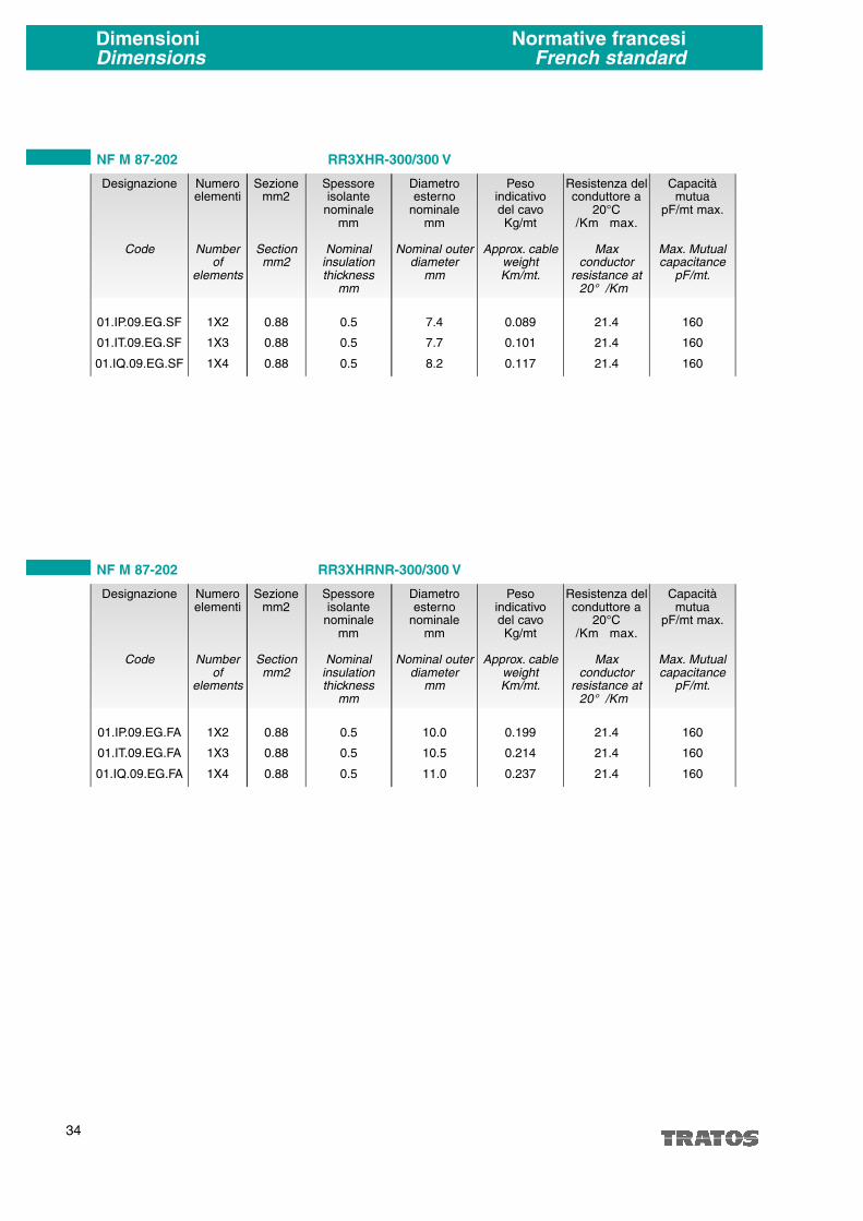
NF M 87-202 RR3XHR-300/300 V
Numeroelementi
Numberof
elements
1X2
1X3
1X4
Sezionemm2
Sectionmm2
0.88
0.88
0.88
Spessoreisolante
nominalemm
Nominalinsulationthickness
mm
0.5
0.5
0.5
Diametroesterno
nominalemm
Nominal outerdiameter
mm
7.4
7.7
8.2
Designazione
Code
01.IP.09.EG.SF
01.IT.09.EG.SF
01.IQ.09.EG.SF
Pesoindicativodel cavoKg/mt
Approx. cableweightKm/mt.
0.089
0.101
0.117
Capacitàmutua
pF/mt max.
Max. Mutualcapacitance
pF/mt.
160
160
160
Resistenza delconduttore a
20°C�/Km max.
Maxconductor
resistance at20° �/Km
21.4
21.4
21.4
NF M 87-202 RR3XHRNR-300/300 V
Numeroelementi
Numberof
elements
1X2
1X3
1X4
Sezionemm2
Sectionmm2
0.88
0.88
0.88
Spessoreisolante
nominalemm
Nominalinsulationthickness
mm
0.5
0.5
0.5
Diametroesterno
nominalemm
Nominal outerdiameter
mm
10.0
10.5
11.0
Designazione
Code
01.IP.09.EG.FA
01.IT.09.EG.FA
01.IQ.09.EG.FA
Pesoindicativodel cavoKg/mt
Approx. cableweightKm/mt.
0.199
0.214
0.237

35
Capacitàmutua
pF/mt max.
Max. Mutualcapacitance
pF/mt.
160
160
160
Resistenza delconduttore a
20°C�/Km max.
Maxconductor
resistance at20° �/Km
21.4
21.4
21.4
NF M 87-202 RR3XHRLNR-300/300 V
Numeroelementi
Numberof
elements
1X2
1X3
1X4
Sezionemm2
Sectionmm2
0.88
0.88
0.88
Spessoreisolante
nominalemm
Nominalinsulationthickness
mm
0.5
0.5
0.5
Diametroesterno
nominalemm
Nominal outerdiameter
mm
12.8
13.4
13.9
Designazione
Code
01.IP.09.EG.PF
01.IT.09.EG.PF
01.IQ.09.EG.PF
Pesoindicativodel cavo
Kg/mt
Approx. cableweightKm/mt.
0.561
0.594
0.673
Capacitàmutua
pF/mt max.
Max. Mutualcapacitance
pF/mt.
145
145
145
145
Resistenza delconduttore a
20°C�/Km max.
Maxconductor
resistance at20° �/Km
37.5
37.5
37.5
37.5
NF M 87-202 UR3XOHR-300/300 V
Numerocoppie
Numberof pairs
7X2
12X2
19X2
27X2
Sezionemm2
Sectionmm2
0.5
0.5
0.5
0.5
Spessoreisolante
nominalemm
Nominalinsulationthickness
mm
0.4
0.4
0.4
0.4
Diametroesterno
nominalemm
Nominal outerdiameter
mm
10.7
14.2
16.7
20.1
Designazione
Code
07.IP.05.EG.SF
12.IP.05.EG.SF
19.IP.05.EG.SF
27.IP.05.EG.SF
Pesoindicativodel cavo
Kg/mt
Approx. cableweightKm/mt.
0.245
0.274
0.404
0.519
DimensioniDimensions
Normative francesiFrench standard

36
DimensioniDimensions
Normative francesiFrench standard
Capacitàmutua
pF/mt max.
Max. Mutualcapacitance
pF/mt.
145
145
145
145
Resistenza delconduttore a
20°C�/Km max.
Maxconductor
resistance at20° �/Km
37.5
37.5
37.5
37.5
NF M 87-202 UR3XOHRNR-300/300 V
Numerocoppie
Numberof pairs
7X2
12X2
19X2
27X2
Sezionemm2
Sectionmm2
0.5
0.5
0.5
0.5
Spessoreisolante
nominalemm
Nominalinsulationthickness
mm
0.4
0.4
0.4
0.4
Diametroesterno
nominalemm
Nominal outerdiameter
mm
14.3
18.0
20.7
24.1
Designazione
Code
07.IP.05.EG.FA
12.IP.05.EG.FA
19.IP.05.EG.FA
27.IP.05.EG.FA
Pesoindicativodel cavoKg/mt
Approx. cableweightKm/mt.
0.328
0.482
0.645
0.840
Capacitàmutua
pF/mt max.
Max. Mutualcapacitance
pF/mt.
145
145
145
145
Resistenza delconduttore a
20°C�/Km max.
Maxconductor
resistance at20° �/Km
37.5
37.5
37.5
37.5
NF M 87-202 UR3XOHRLNR-300/300 V
Numerocoppie
Numberof pairs
7X2
12X2
19X2
27X2
Sezionemm2
Sectionmm2
0.5
0.5
0.5
0.5
Spessoreisolante
nominalemm
Nominalinsulationthickness
mm
0.4
0.4
0.4
0.4
Diametroesterno
nominalemm
Nominal outerdiameter
mm
17.3
21.0
23.6
27.4
Designazione
Code
07.IP.05.EG.PT
12.IP.05.EG.PT
19.IP.05.EG.PT
27.IP.05.EG.PT
Pesoindicativodel cavoKg/mt
Approx. cableweightKm/mt.
0.901
1.238
1.542
1.996
37
Capacitàmutua
pF/mt max.
Max. Mutualcapacitance
pF/mt.
145
145
Resistenza delconduttore a
20°C�/Km max.
Maxconductor
resistance at20° �/Km
37.5
37.5
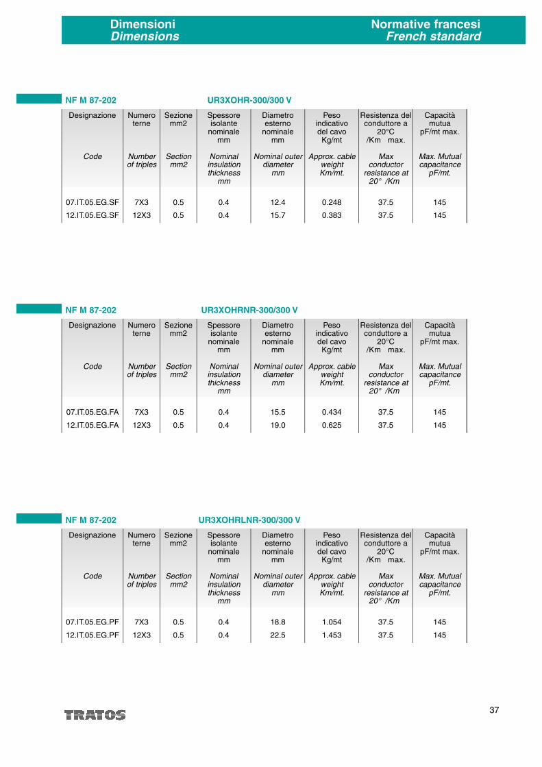
NF M 87-202 UR3XOHR-300/300 V
Numeroterne
Numberof triples
7X3
12X3
Sezionemm2
Sectionmm2
0.5
0.5
Spessoreisolante
nominalemm
Nominalinsulationthickness
mm
0.4
0.4
Diametroesterno
nominalemm
Nominal outerdiameter
mm
12.4
15.7
Designazione
Code
07.IT.05.EG.SF
12.IT.05.EG.SF
Pesoindicativodel cavo
Kg/mt
Approx. cableweightKm/mt.
0.248
0.383
Capacitàmutua
pF/mt max.
Max. Mutualcapacitance
pF/mt.
145
145
Resistenza delconduttore a
20°C�/Km max.
Maxconductor
resistance at20° �/Km
37.5
37.5
NF M 87-202 UR3XOHRNR-300/300 V
Numeroterne
Numberof triples
7X3
12X3
Sezionemm2
Sectionmm2
0.5
0.5
Spessoreisolante
nominalemm
Nominalinsulationthickness
mm
0.4
0.4
Diametroesterno
nominalemm
Nominal outerdiameter
mm
15.5
19.0
Designazione
Code
07.IT.05.EG.FA
12.IT.05.EG.FA
Pesoindicativodel cavo
Kg/mt
Approx. cableweightKm/mt.
0.434
0.625
Capacitàmutua
pF/mt max.
Max. Mutualcapacitance
pF/mt.
145
145
Resistenza delconduttore a
20°C�/Km max.
Maxconductor
resistance at20° �/Km
37.5
37.5
NF M 87-202 UR3XOHRLNR-300/300 V
Numeroterne
Numberof triples
7X3
12X3
Sezionemm2
Sectionmm2
0.5
0.5
Spessoreisolante
nominalemm
Nominalinsulationthickness
mm
0.4
0.4
Diametroesterno
nominalemm
Nominal outerdiameter
mm
18.8
22.5
Designazione
Code
07.IT.05.EG.PF
12.IT.05.EG.PF
Pesoindicativodel cavo
Kg/mt
Approx. cableweightKm/mt.
1.054
1.453
DimensioniDimensions
Normative francesiFrench standard

38
DimensioniDimensions
Normative italianeItalian standard
Capacitàmutua
pF/mt max.
Max. Mutualcapacitance
pF/mt.
140
140
140
140
140
140
Resistenza delconduttore a
20°C�/Km max.
Maxconductor
resistance at20° �/Km
13.3
13.3
13.3
13.3
13.3
13.3
ENI 18100 REV. 11/83 FR2XOHR-450/750 V
Numerocoppie
Numberof pairs
1
2
3
6
12
24
Sezionemm2
Sectionmm2
1.5
1.5
1.5
1.5
1.5
1.5
Spessoreisolante
nominalemm
Nominalinsulationthickness
mm
0.8
0.8
0.8
0.8
0.8
0.8
Diametroesterno
nominalemm
Nominal outerdiameter
mm
10.2
14.0
16.0
20.0
27.2
38.0
Designazione
Code
62185320130
62188220030
62188220130
62188220230
62188220330
62188220530
Pesoindicativodel cavoKg/mt
Approx. cableweightKm/mt.
0.156
0.225
0.325
0.456
0.847
1.594
Capacitàmutua
pF/mt max.
Max. Mutualcapacitance
pF/mt.
140
140
140
140
140
140
Resistenza delconduttore a
20°C�/Km max.
Maxconductor
resistance at20° �/Km
13.3
13.3
13.3
13.3
13.3
13.3
ENI 18100 REV. 11/83 FR2XOHR-450/750 V
Numeroterne
Numberof triples
1
2
3
6
12
24
Sezionemm2
Sectionmm2
1.5
1.5
1.5
1.5
1.5
1.5
Spessoreisolante
nominalemm
Nominalinsulationthickness
mm
0.8
0.8
0.8
0.8
0.8
0.8
Diametroesterno
nominalemm
Nominal outerdiameter
mm
10.6
15.8
16.7
22.0
30.0
42.2
Designazione
Code
62185620330
62188320030
62188320130
62188320230
62188320330
62188320530
Pesoindicativodel cavoKg/mt
Approx. cableweightKm/mt.
0.180
0.270
0.354
0.622
1.184
2.252

39
Capacitàmutua
pF/mt max.
Max. Mutualcapacitance
pF/mt.
140
140
140
140
140
140
Resistenza delconduttore a
20°C�/Km max.
Maxconductor
resistance at20° �/Km
13.3
13.3
13.3
13.3
13.3
13.3
ENI 18100 REV. 11/83 FR2XOHRFR-450/750 V
Numerocoppie
Numberof pairs
1(*)
2(*)
3(*)
6
12
24
Sezionemm2
Sectionmm2
1.5
1.5
1.5
1.5
1.5
1.5
Spessoreisolante
nominalemm
Nominalinsulationthickness
mm
0.8
0.8
0.8
0.8
0.8
0.8
Diametroesterno
nominalemm
Nominal outerdiameter
mm
14.0
18.3
21.3
25.7
32.8
43.7
Designazione
Code
62185421130
62188221030
62188221130
62188221230
62188221330
62188221530
Pesoindicativodel cavo
Kg/mt
Approx. cableweightKm/mt.
0.309
0.455
0.635
0.942
1.488
2.630
Capacitàmutua
pF/mt max.
Max. Mutualcapacitance
pF/mt.
140
140
140
140
140
140
Resistenza delconduttore a
20°C�/Km max.
Maxconductor
resistance at20° �/Km
13.3
13.3
13.3
13.3
13.3
13.3
ENI 18100 REV. 11/83 FR2XOHRFR-450/750 V
Numeroterne
Numberof triples
1(*)
2(*)
3
6
12
24
Sezionemm2
Sectionmm2
1.5
1.5
1.5
1.5
1.5
1.5
Spessoreisolante
nominalemm
Nominalinsulationthickness
mm
0.8
0.8
0.8
0.8
0.8
0.8
Diametroesterno
nominalemm
Nominal outerdiameter
mm
14.6
20.8
22.2
27.1
35.3
47.8
Designazione
Code
62185620330
62188320030
62188320130
62188320230
62188320330
62188320530
Pesoindicativodel cavo
Kg/mt
Approx. cableweightKm/mt.
0.340
0.604
0.782
1.093
2.160
3.325
DimensioniDimensions
Normative italianeItalian standard
NOTA: (*) Armature a treccia acciaio sostituire nelle sigla (A) alla (F)
NOTA: (*) Armature a treccia acciaio sostituire nelle sigla (A) alla (F)

40
DimensioniDimensions
Normative italianeItalian standard
Capacitàmutua
pF/mt max.
Max. Mutualcapacitance
pF/mt.
140
140
140
140
140
140
Resistenza delconduttore a
20°C�/Km max.
Maxconductor
resistance at20° �/Km
13.3
13.3
13.3
13.3
13.3
13.3
ENI 18100 REV. 11/83 FR2XOHRLRFR-450/750 V
Numerocoppie
Numberof pairs
1
2
3
6
12
24
Sezionemm2
Sectionmm2
1.5
1.5
1.5
1.5
1.5
1.5
Spessoreisolante
nominalemm
Nominalinsulationthickness
mm
0.8
0.8
0.8
0.8
0.8
0.8
Diametroesterno
nominalemm
Nominal outerdiameter
mm
19.7
23.7
24.8
30.5
37.6
49.0
Designazione
Code
621854213130
621882213030
621882213130
621882213230
621882213330
621882213530
Pesoindicativodel cavoKg/mt
Approx. cableweightKm/mt.
0.967
1.308
1.436
2.000
2.970
4.516
Capacitàmutua
pF/mt max.
Max. Mutualcapacitance
pF/mt.
140
140
140
140
140
140
Resistenza delconduttore a
20°C�/Km max.
Maxconductor
resistance at20° �/Km
13.3
13.3
13.3
13.3
13.3
13.3
ENI 18100 REV. 11/83 FR2XOHRLRFR-450/750 V
Numeroterne
Numberof triples
1
2
3
6
12
24
Sezionemm2
Sectionmm2
1.5
1.5
1.5
1.5
1.5
1.5
Spessoreisolante
nominalemm
Nominalinsulationthickness
mm
0.8
0.8
0.8
0.8
0.8
0.8
Diametroesterno
nominalemm
Nominal outerdiameter
mm
21.3
25.7
27.3
32.2
40.3
53.0
Designazione
Code
621856213330
621883213030
621883213130
621883213230
621883213330
621883213530
Pesoindicativodel cavoKg/mt
Approx. cableweightKm/mt.
1.065
1.460
1.682
2.260
3.600
5.440
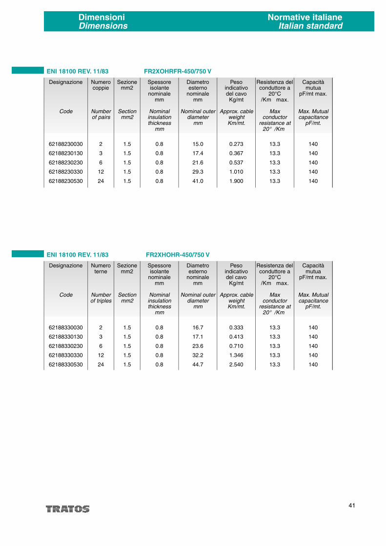
41
Capacitàmutua
pF/mt max.
Max. Mutualcapacitance
pF/mt.
140
140
140
140
140
Resistenza delconduttore a
20°C�/Km max.
Maxconductor
resistance at20° �/Km
13.3
13.3
13.3
13.3
13.3
ENI 18100 REV. 11/83 FR2XOHRFR-450/750 V
Numerocoppie
Numberof pairs
2
3
6
12
24
Sezionemm2
Sectionmm2
1.5
1.5
1.5
1.5
1.5
Spessoreisolante
nominalemm
Nominalinsulationthickness
mm
0.8
0.8
0.8
0.8
0.8
Diametroesterno
nominalemm
Nominal outerdiameter
mm
15.0
17.4
21.6
29.3
41.0
Designazione
Code
62188230030
62188230130
62188230230
62188230330
62188230530
Pesoindicativodel cavo
Kg/mt
Approx. cableweightKm/mt.
0.273
0.367
0.537
1.010
1.900
Capacitàmutua
pF/mt max.
Max. Mutualcapacitance
pF/mt.
140
140
140
140
140
Resistenza delconduttore a
20°C�/Km max.
Maxconductor
resistance at20° �/Km
13.3
13.3
13.3
13.3
13.3
ENI 18100 REV. 11/83 FR2XHOHR-450/750 V
Numeroterne
Numberof triples
2
3
6
12
24
Sezionemm2
Sectionmm2
1.5
1.5
1.5
1.5
1.5
Spessoreisolante
nominalemm
Nominalinsulationthickness
mm
0.8
0.8
0.8
0.8
0.8
Diametroesterno
nominalemm
Nominal outerdiameter
mm
16.7
17.1
23.6
32.2
44.7
Designazione
Code
62188330030
62188330130
62188330230
62188330330
62188330530
Pesoindicativodel cavo
Kg/mt
Approx. cableweightKm/mt.
0.333
0.413
0.710
1.346
2.540
DimensioniDimensions
Normative italianeItalian standard
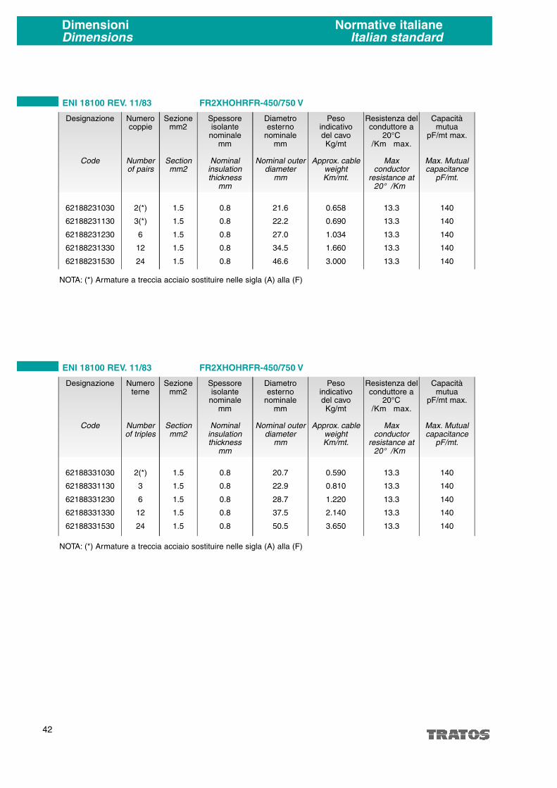
42
DimensioniDimensions
Normative italianeItalian standard
Capacitàmutua
pF/mt max.
Max. Mutualcapacitance
pF/mt.
140
140
140
140
140
Resistenza delconduttore a
20°C�/Km max.
Maxconductor
resistance at20° �/Km
13.3
13.3
13.3
13.3
13.3
ENI 18100 REV. 11/83 FR2XHOHRFR-450/750 V
Numerocoppie
Numberof pairs
2(*)
3(*)
6
12
24
Sezionemm2
Sectionmm2
1.5
1.5
1.5
1.5
1.5
Spessoreisolante
nominalemm
Nominalinsulationthickness
mm
0.8
0.8
0.8
0.8
0.8
Diametroesterno
nominalemm
Nominal outerdiameter
mm
21.6
22.2
27.0
34.5
46.6
Designazione
Code
62188231030
62188231130
62188231230
62188231330
62188231530
Pesoindicativodel cavoKg/mt
Approx. cableweightKm/mt.
0.658
0.690
1.034
1.660
3.000
Capacitàmutua
pF/mt max.
Max. Mutualcapacitance
pF/mt.
140
140
140
140
140
Resistenza delconduttore a
20°C�/Km max.
Maxconductor
resistance at20° �/Km
13.3
13.3
13.3
13.3
13.3
ENI 18100 REV. 11/83 FR2XHOHRFR-450/750 V
Numeroterne
Numberof triples
2(*)
3
6
12
24
Sezionemm2
Sectionmm2
1.5
1.5
1.5
1.5
1.5
Spessoreisolante
nominalemm
Nominalinsulationthickness
mm
0.8
0.8
0.8
0.8
0.8
Diametroesterno
nominalemm
Nominal outerdiameter
mm
20.7
22.9
28.7
37.5
50.5
Designazione
Code
62188331030
62188331130
62188331230
62188331330
62188331530
Pesoindicativodel cavoKg/mt
Approx. cableweightKm/mt.
0.590
0.810
1.220
2.140
3.650
NOTA: (*) Armature a treccia acciaio sostituire nelle sigla (A) alla (F)
NOTA: (*) Armature a treccia acciaio sostituire nelle sigla (A) alla (F)

43
Capacitàmutua
pF/mt max.
Max. Mutualcapacitance
pF/mt.
140
140
140
140
140
Resistenza delconduttore a
20°C�/Km max.
Maxconductor
resistance at20° �/Km
13.3
13.3
13.3
13.3
13.3
ENI 18100 REV. 11/83 FR2XHOHRLRFR-450/750 V
Numerocoppie
Numberof pairs
2
3
6
12
24
Sezionemm2
Sectionmm2
1.5
1.5
1.5
1.5
1.5
Spessoreisolante
nominalemm
Nominalinsulationthickness
mm
0.8
0.8
0.8
0.8
0.8
Diametroesterno
nominalemm
Nominal outerdiameter
mm
24.7
25.7
31.5
39.4
52.0
Designazione
Code
621882313030
621882313130
621882313230
621882313330
621882313530
Pesoindicativodel cavo
Kg/mt
Approx. cableweightKm/mt.
1.402
1.532
2.137
3.233
5.023
Capacitàmutua
pF/mt max.
Max. Mutualcapacitance
pF/mt.
140
140
140
140
140
Resistenza delconduttore a
20°C�/Km max.
Maxconductor
resistance at20° �/Km
13.3
13.3
13.3
13.3
13.3
ENI 18100 REV. 11/83 FR2XHOHRLRFR-450/750 V
Numeroterne
Numberof triples
2
3
6
12
24
Sezionemm2
Sectionmm2
1.5
1.5
1.5
1.5
1.5
Spessoreisolante
nominalemm
Nominalinsulationthickness
mm
0.8
0.8
0.8
0.8
0.8
Diametroesterno
nominalemm
Nominal outerdiameter
mm
25.7
26.7
33.5
42.7
55.6
Designazione
Code
621883313030
621883313130
621883313230
621883313330
621883313530
Pesoindicativodel cavo
Kg/mt
Approx. cableweightKm/mt.
1.516
1.720
2.480
3.665
6.083
DimensioniDimensions
Normative italianeItalian standard

LSHFcompound
3,4
> 1.500
> 1.5
90
Buono
Autoestinguente e
ritardante la fiamma
TIPO DI ISOLANTE
Sezione
0,50 mm2
0,75 mm2
1,00 mm2
1,50 mm2
2,50 mm2
20 AWG
18 AWG
16 AWG
44
Conduttori per cavi strumenti
Caratteristiche dei materiali isolanti più usati
I conduttori per cavi strumenti sono normalmente in rame rosso o stagnato su richiesta, a filo unico, semirigidoo flessibile in accordo alla normativa internazionale IEC 60228 (classe 1, 2, 5) o altre normative equivalenti.
Rigido(classe 1)
Semirgido(classe 2)
Flessibile(classe 5)
N. filix diam.
mm.
1 x 0,80
1 x 0,97
1 x 1,13
1 x 1,38
1 x 1,78
1 x 0,81
1 x 1,02
1 x 1,29
Diam.condutt.
mm.
0,80
0,97
1,13
1,38
1,78
0,81
1,02
1,29
RE 20° Cohm/Km.
36
24,5
18,1
12,1
7,41
34,2
21,6
13,6
N. filix diam.
mm.
7 x 0,31
7 x 0,37
7 x 0,43
7 x 0,53
7 x 0,67
7 x 0,32
7 x 0,40
7 x 0,51
Diam.condutt.
mm.
0,93
1,11
1,29
1,59
2,01
0,96
1,20
1,53
RE 20° Cohm/Km.
36
24,5
18,1
12,1
7,41
32,5
20,4
12,8
N. filix diam.
mm.
16 x 0,20
24 x 0,20
32 x 0,20
30 x 0,25
50 x 0,25
19 x 0,20
19 x 0,25
19 x 0,29
Diam.condutt.
mm.
0,94
1,20
1,30
1,68
2,10
1,00
1,25
1,45
Conduttore rigido classe 1 Conduttore semirigido classe 2
Tutte le dimensioni suddette sono nominali. Ai fini della determinazione della qualità del conduttore fa fede il valore della
resistenza elettrica richiesta nelle normative tecniche di riferimento.
TIPO DI CONDUTTORE
PolietilenePE
2,3
> 10.000
> 10
70 (LD)*
80 (HD)*
Buono
Infiammabile
(2)
Polietilenereticolato
XLPE
2,3
> 10.000
> 10
90
Buono
Infiammabile
(2)
Silicone
3,6
> 1.500
> 1.5
180
Molto
Buono
(2)
(1) caratteristica dell'isolante molto importante per determinare il valore della capacità mutua
(2) può essere reso autoestinguente ma con conseguente perdita di alcuni parametri elettrici
* LD Bassa densità
* HD Alta densità
PolivinilcloruroPVC
4 - 6,5
> 750
> 0,750
70 - 90 - 105
Tendenza ad irrigidirsi
e a divenire fragile
Autoestinguente e
ritardante la fiamma
Caratteristiche
Costante dielettrica Er (1)
Costante isol. 20° C
70° C
Temperatura
massima °C
Comportamento alle
basse temperature
Fiammabilità
RE 20° Cohm/Km.
39
26
19,5
13,3
7,98
30,3
19,4
15,2
Conduttore flessibile classe 5

45
Section
0.50 mm2
0.75 mm2
1.00 mm2
1.50 mm2
2.50 mm2
20 AWG
18 AWG
16 AWG
Conductors for instrumentation cables
Characteristics of the insulating materials
The conductors for instrumentation cables are normally plain copper or tinned upon request, solid, stranded,or flexible in accordance to the international standard IEC 60228 (class 1, 2, 5) or other equivalent standards.
Solid(class 1)
Stranded(class 2)
Flexible(class 5)
N. wiresx diam.
mm.
1 x 0.80
1 x 0.97
1 x 1.13
1 x 1.38
1 x 1.78
1 x 0.81
1 x 1.02
1 x 1.29
Diam.conductor
mm.
0.80
0.97
1.13
1.38
1.78
0.81
1.02
1.29
RE 20° Cohm/Km.
36
24.5
18.1
12.1
7.41
34.2
21.6
13.6
N. wiresx diam.
mm.
7 x 0.31
7 x 0.37
7 x 0.43
7 x 0.53
7 x 0.67
7 x 0.32
7 x 0.40
7 x 0.51
Diam.conductor
mm.
0.93
1.11
1.29
1.59
2.01
0.96
1.20
1.53
RE 20° Cohm/Km.
36
24.5
18.1
12.1
7.41
32.5
20.4
12.8
N. filix diam.
mm.
16 x 0.20
24 x 0.20
32 x 0.20
30 x 0.25
50 x 0.25
19 x 0.20
19 x 0.25
19 x 0.29
Diam.conductor
mm.
0.94
1.20
1.30
1.68
2.10
1.00
1.25
1.45
RE 20° Cohm/Km.
39
26
19.5
13.3
7.98
30.3
19.4
15.2
Solid conductor class 1 Stranded conductor class 2 Flexible conductor class 5
All above dimensions are nominal. In order to determine the conductor quality take into consideration the electrical resi-stance value requested by the technical norms of reference.
PolyethylenePE
2.3
> 10.000
> 10
70 (LD)*
80 (HD)*
Good
Flammable
(2)
Cross-linkedpolyethylene
XLPE
2.3
> 10.000
> 10
90
Good
Flammable
(2)
Silicone
3.6
> 1.500
> 1.5
180
Excellent
(2)
(1) very important insulation characteristic in order to determine the mutal capacitance value(2) can be autoextinguishing but with loss of some electrical parameters* LD Low density* HD High density
Polyvinyl-chloridePVC
4 - 6.5
> 750
> 0.750
70 - 90 - 105
Tendency to stiffen
and become weak
Selfextinguishing and
flame retardant
Characteristics
Dielectric constant Er (1)
Insulation constant 20° C
70° C
Max
temperature °C
Behaviour to low
temperatures
Flammability
LSHFcompound
3.4
> 1.500
> 1.5
90
Good
Selfextinguishing and
flame retardant
CONDUCTOR TYPE
INSULATING TYPE

Applicazioneusuale
Usual application
Resistenza alla penetrazione
Penetration resistance
Resistenzaal taglio
Cuttingresistance
Flessibilità
Flexibllity
Barrieraumidità
Moisturebarrier
Copertura
Coverage
Rif.
Ref.
Tipo di armatura
Type of armouring
46
ArmatureArmourings
A treccia di fili di acciaio zincato
Galvanized steel wires braid
A doppio nastro diacciaio zincatoa coprigiunto
Double galvanized steel tape overlapping
A fili di acciaio zincatoe nastro controspirale
Galvanized steel wire andoverlap tape
A piattina di acciaio zincato e nastro controspirale
Galvanized steel strip andreciprocating lay tape
A fili di acciaio zincatocon zingatura rinforzata
Galvanized steel wires withreinforced galvanization
Nastro corrugato di acciao
Corrugated steel tape
Nastro liscio di alluminiotermosaldato
Thermo-welded aluminiumplain tape
Diametri� 15 mm
Diameters� 15 mm
Diametri> 15 mm
Diameters> 15 mm
Tutti i diametri
All diameters
Diametri> 15 mm
Diameters> 15 mm
Tutti idiametri
All diameters
Tutti idiametri
All diameters
Tutti idiametri
All diameters
S
S
O
O
S
S
B
B
B
B
O
O
B
B
80%
80%
100%
100%
90%
90%
90%
90%
90%
90%
100%
100%
100%
100%
1
1
2
2
3
3
4
4
5
5
6
6
7
7
B
B
O
O
B
B
O
O
O
O
O
O
B
B
B
B
C
C
S
S
S
S
B
B
C
C
C
C
B
B
C
C
S
S
S
S
B
B
C
C
C
C
1
2
5
3
4
7
6
(C) Cattivo
(S) Scarso
(B) Buono
(O) Ottimo
(C) Bad
(S) Moderate
(B) Good
(O) Very good

U
R
F
R
R2
R3
E
E4
G4
G6
G7
G10
H
H1
H2
H5
L
A2
A
F
N
Z
SWA
H5
A3
H6
R
E
G4
K
M1
M2
X
XH
XOH
XHO
XHOH
XOR
M
/1.5
/2
/3
/4
CONDUTTORE
Filo unico rigido Classe 1
Corda semirigida Classe 2
Flessibile Classe 5
ISOLANTE
Polivinilcloruro 70°C
Polivinilcloruro 80/90°C
Polivinilcloruro 105°C
Polietilene
Polietilene XLPE
Silicone 180°C
Polietilene clorosolfonáto
Gomma etilenpropilenica 90°C
LSHF compound 90°C
SCHERMO
Alluminio accoppiato
Nastri o fili di rame
Treccia di fili di rame
Alluminio termosaldato
GUAINA METALLICA
Piombo estruso
Alluminio estruso
ARMATURA
Treccia di acciaio zincato
Fili di acciaio zincato e nastro controspirale
Nastri di acciaio zincato
Piattine di acciaio zincato e nastro controspirale
Fili di acciaio zincato rinforzati
Alluminio termosaldato
Alluminio corrugato
Acciaio corrugato
GUAINA NON METALLICA
PVC 70/90/105°C
Polietilene
Silicone
Policloroprene
LSHF compound termoplastico
LSHF compound reticolato
ALTRI SIMBOLI
Conduttori riuniti a coppie/ terne/quarte (elementi)
Elementi schermati singolarmente
Elementi riuniti con solo schermo generale
Elementi riuniti con solo schermo singolo
Elementi riuniti con solo schermo singolo e generele
Elementi riuniti senza schermi
Nastro vetro/mica
TENSIONE D'IMPIEGO
300/300V
300/500V
450/750V
600/1000V
47
Codici produttoreManufactored codes
CONDUCTOR
Solid Class 1
Stranded Class 2
Flexible Class 5
INSULATION
Polyvinylchloride 70°C
Polyvinylchloride 80/90°C
Polivinvlchloride 105°C
Polyethylene
Polyethylene XLPE
Silicone 180°C
ChlorosulPhonated Polyethylene
Ethylene propylene rubber 90°C
LSHF compound 90°C
SCREEN
Plastic coated aluminium
Copper tapes or wires
Copper wires braid
Thermosealed aluminium
METALLIC SHEATH
Extruded lead
Extruded aluminium
ARMOURING
Galvanized steel braid
Galvanized stell wires with holding tape
Galvanized steel tapes
Galvanized flat steel wires with holding tapes
Galvanized strengthened steel wires
Thermosealed aluminium tape
Corrugated aluminium tape
Corrugated steell tape
NO METALLIC SHEATH
PVC 70/90/105°C
Polyethylene
Silicone
Polychloroprene
LSHF thermoplastic compound
LSHF cross linked compound
OTHER SYMBOLS
Conductors twisted in pairs/ triples/quads (as elements)
Individual screened elements
Assembled elements with overall screen only
Assembled elements with individual screen only
Assembled elements with individual and overall screen
Assembled elements without screens
Glass/mica tape
RATED VOLTAGE
300/300V
300/500V
450/750V
600/ 1000V
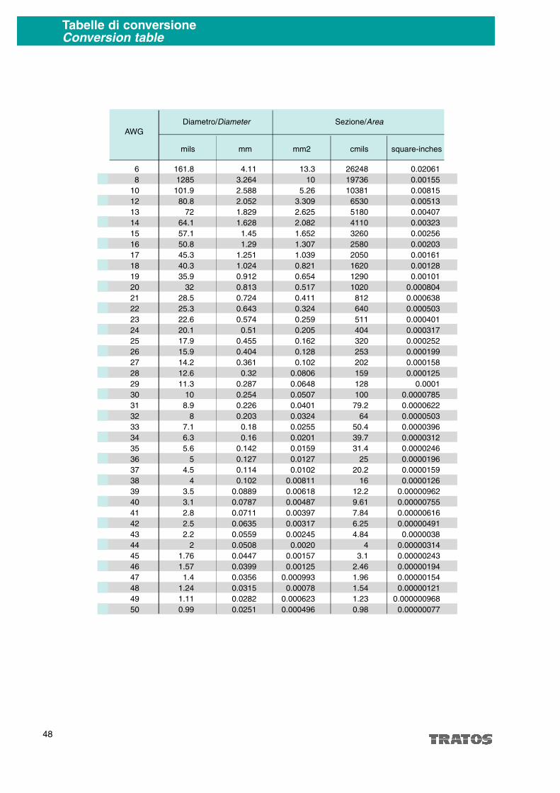
48
6 161.8 4.11 13.3 26248 0.02061
8 1285 3.264 10 19736 0.00155
10 101.9 2.588 5.26 10381 0.00815
12 80.8 2.052 3.309 6530 0.00513
13 72 1.829 2.625 5180 0.00407
14 64.1 1.628 2.082 4110 0.00323
15 57.1 1.45 1.652 3260 0.00256
16 50.8 1.29 1.307 2580 0.00203
17 45.3 1.251 1.039 2050 0.00161
18 40.3 1.024 0.821 1620 0.00128
19 35.9 0.912 0.654 1290 0.00101
20 32 0.813 0.517 1020 0.000804
21 28.5 0.724 0.411 812 0.000638
22 25.3 0.643 0.324 640 0.000503
23 22.6 0.574 0.259 511 0.000401
24 20.1 0.51 0.205 404 0.000317
25 17.9 0.455 0.162 320 0.000252
26 15.9 0.404 0.128 253 0.000199
27 14.2 0.361 0.102 202 0.000158
28 12.6 0.32 0.0806 159 0.000125
29 11.3 0.287 0.0648 128 0.0001
30 10 0.254 0.0507 100 0.0000785
31 8.9 0.226 0.0401 79.2 0.0000622
32 8 0.203 0.0324 64 0.0000503
33 7.1 0.18 0.0255 50.4 0.0000396
34 6.3 0.16 0.0201 39.7 0.0000312
35 5.6 0.142 0.0159 31.4 0.0000246
36 5 0.127 0.0127 25 0.0000196
37 4.5 0.114 0.0102 20.2 0.0000159
38 4 0.102 0.00811 16 0.0000126
39 3.5 0.0889 0.00618 12.2 0.00000962
40 3.1 0.0787 0.00487 9.61 0.00000755
41 2.8 0.0711 0.00397 7.84 0.00000616
42 2.5 0.0635 0.00317 6.25 0.00000491
43 2.2 0.0559 0.00245 4.84 0.0000038
44 2 0.0508 0.0020 4 0.00000314
45 1.76 0.0447 0.00157 3.1 0.00000243
46 1.57 0.0399 0.00125 2.46 0.00000194
47 1.4 0.0356 0.000993 1.96 0.00000154
48 1.24 0.0315 0.00078 1.54 0.00000121
49 1.11 0.0282 0.000623 1.23 0.000000968
50 0.99 0.0251 0.000496 0.98 0.00000077
Tabelle di conversioneConversion table
AWG
mils mm mm2 cmils square-inches
Diametro/Diameter Sezione/Area

Tera
Giga
Maga
Kilo
Hecto
Deca
Deci
Centi
Milli
Micro
Nano
Pico
T
G
M
k
h
da
d
c
m
µ
n
p
1012
109
106
103
102
101
10-1
10-2
10-3
10-6
10-9
10-12
49
Tabelle di conversioneConversion table
LENGTH-English
Mils
Mils
Inches
Inches
Inches
Feet
Feet
Feet (Thousands of)
Yards
Miles
VOLUME-English
Cubic inches
Cubic feet
Quarts (Liquid U.S.)
Gallons (U.S.)
AREA-English
Square mils
Square mils
Circular mils
Circular mils
Circular mils
Square inches
Square inches
Square inches
Square inches
Square feet
Square yards
WEIGHT-English
Ounces
Pounds (Av.)
Pounds (Av.)
Tons (short)
Tons (long)
.001
.0254
1000.
25.40
2.54
30.48
.3048
.3048
.9144
1.6093
16.38716
.028317
.9463
3.7854
1.2732
.000001
.7854
.0000007854
.0005067
1000000.
1273240.
645.16
6.4516
.09290
.8361
28.3495
453.59
.45359
907.19
1016.05
inches
millimeters
mils
millimeters
centimeters
centimeters
meters
kilometers
meters
kilometers
cubic centimeters
cubic meters
liters
liters
circular mils
square inches
square mils
square inches
square millimeters
square mils
circular mils
square millimeters
square centimeters
square meters
square meters
grams
grams
kilograms
kilogramas
kilograms
Moltiplica
Multiply
per
by
si ottiene
to obtain
LENGTH-Metric
Millimeters
Millimeters
Centimeters
Centimeters
Meters
Meters
Meters
Kilometers
Kilometers
VOLUME-Metric
Cubic centimeters
Cubic meters
Liters
Liters
AREA-Metric
Square millimeters
Square millimeters
Square centimeters
Square meters
Square meters
WEIGHT-Metric
Grams
Grams
Kilograms
Kilograms
Kilograms
Kilograms
39.37
.03937
.3937
.032808
39.37
3.2808
1.0936
3280.83
.62137
.06102
35.3145
1.05668
.26417
1973.52
.00155
.155
10.7638
1.19599
.03527
.002205
35.274
2.2046
.001102
.0009842
mils
inches
inches
feet
inches
feet
yards
feet
miles
cubic inches
cubic feet
quarts (Liquid U.S.)
U.S. Gallons
circular mils
square inches
square inches
square feet
square yards
ounces
pounds
ounces
pounds
tons (short)
tons (long)
Moltiplica
Multiply
per
by
si ottiene
to obtain
ELECTRICAL UNIT PER LENGHT
METRIC PREFIX
1 µF per mile
1 M� per mile
1 decibel per mile
1 pf per foot
1 decibel per 1000 ft
1 M� per 1000 ft
= 0.62 µF/km
= 1.61 M� x km
= 0.62 dB/km
= 3.28 pF/m
= 3.28 dB/km
= 3.28 �/km
Prefisso
Prefix
Simbolo
Symbol
Valore
Value

50
Prove finaliFinal test
Prove di accettazione
Prove di tipo
Usualy tests
Type tests
Prova
Esame generale
Dimensioni
Spessore isolante
Spessore guaine
Caratteristiche termiche e meccaniche
dell'isolante prima dell'invecchiamento
Caratteristiche termiche e meccaniche
delle guaine prima dell'invecchiamento
Caratteristiche termiche e meccaniche
dell'isolante dopo l'invecchiamento
Caratteristiche termiche e meccaniche
della guaina dopo l'invecchiamento
Rigidità dielettrica
Continuità conduttori
Continuità schermo
Resistenza elettrica
Capacità mutua
Induttanza
Resistenza di isolamento
Tossicità
Densità fumi
Autoestinguenza
Indice di ossigeno
Indice di temperatura
Non propagazione della fiamma
Resistenza al fuoco
Altri prove fisiche, chimiche e meccaniche
Test
General control
Dimensions
Thickness insulation
Thickness sheath
Thermal and mechanical properties
of insulation before ageing
Thermal and mechanical properties
of sheath before of ageing
Thermal and mechanical properties
of insulation after ageing
Thermal and mechanical properties
of sheaths after ageing
Dielectric strength
Continuity wires
Continuity screen
Electrical resistance
Mutual capacity
Inductance
Insulation resistance
Toxicity
Fumes density
Selfestinguish
Oxygene index
Temperature index
Flame retardant
Fire resisting
Other phisical, chemical and mechanical test
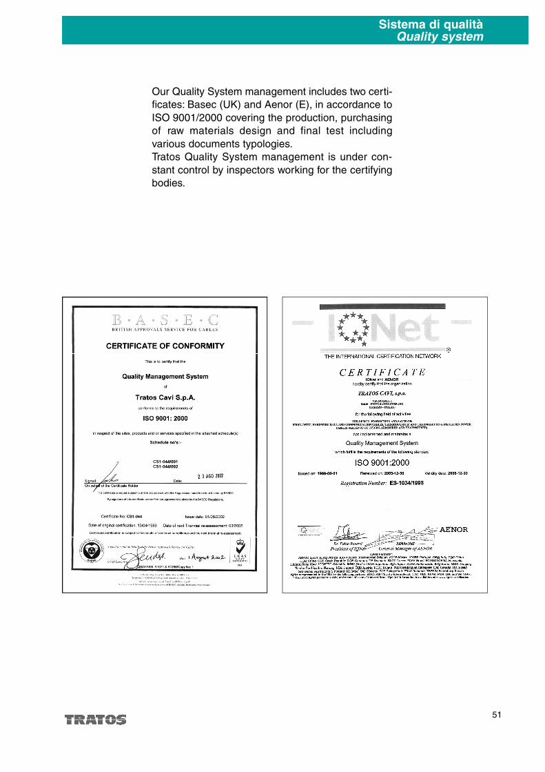
51
Sistema di qualitàQuality system
Our Quality System management includes two certi-
ficates: Basec (UK) and Aenor (E), in accordance to
ISO 9001/2000 covering the production, purchasing
of raw materials design and final test including
various documents typologies.
Tratos Quality System management is under con-
stant control by inspectors working for the certifying
bodies.
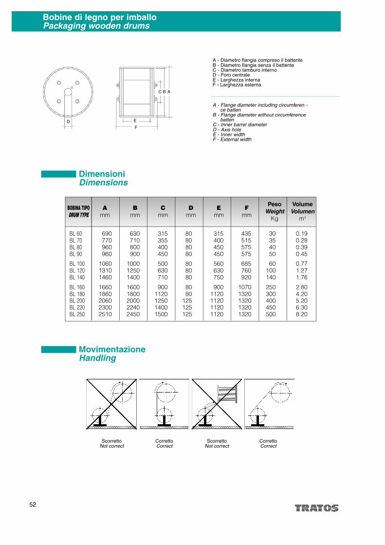
0.190.280.390.45
0.771.271.76
2.804.205.206.308.20
435515575575
685760920
10701320132013201320
BL 60BL 70BL 80BL 90
BL 100BL 120BL 140
BL 160BL 180BL 200BL 220BL 250
690770960960
106013101460
16601860206023002510
630710800900
100012501400
16001800200022402450
315355400450
500630710
9001120125014001500
80808080
808080
8080
125125125
315400450450
560630750
9001120112011201120
30354050
60100140
250300400450500
52
Bobine di legno per imballoPackaging wooden drums
BOBINA TIPO
DRUM TYPE
F
mm
A
mm
B
mm
C
mm
D
mm
E
mm
Pe s o
We i g h t
Kg
Vo l u m e
Vo l u m e n
m3
A - Diametro flangia compreso il battenteB - Diametro flangia senza il battenteC - Diametro tamburo internoD - Foro centraleE - Larghezza internaF - Larghezza esterna
A - Flange diameter including circumferen -ce batten
B - Flange diameter without circumferencebatten
C - Inner barrel diameter D - Axis hole E - Inner width F - External width
D E
C B A
F
DimensioniDimensions
MovimentazioneHandling
ScorrettoNot correct
CorrettoCorrect
ScorrettoNot correct
CorrettoCorrect

1535
1405
1290
1190
1100
1020
950
885
825
775
725
685
640
605
575
540
515
490
465
440
420
400
385
365
350
335
320
310
295
metri metres
6
7
8
9
10
11
12
13
14
15
16
17
18
19
20
21
22
23
24
25
26
27
28
29
30
32
34
36
38
40
42
44
46
48
50
52
54
56
58
60
62
64
66
68
70
72
74
76
78
80
82
84
86
88
90
92
94
96
98
100
53
1575
1420
1290
1175
1075
985
910
840
780
725
675
630
590
555
520
490
465
440
415
390
370
355
340
320
305
290
280
265
255
245
235
225
3590
2600
2000
1590
1290
1000
850
750
650
550
500
450
400
350
320
293
267
244
224
206
191
177
165
153
143
126
121
99
89
2000
1800
1500
1350
1150
1000
900
800
700
650
600
550
500
450
410
379
352
327
305
285
250
222
198
177
160
145
132
121
111
102
94
1420
1250
1200
990
890
800
725
660
605
555
510
470
440
410
380
355
330
310
295
275
260
245
230
220
210
200
190
181
173
165
158
151
144
138
133
2100
2000
1750
1600
1500
1400
1350
1200
1100
1000
900
800
700
650
575
500
475
435
400
370
340
320
295
275
255
240
225
212
200
188
178
168
160
152
144
137
131
125
119
114
109
104
100
96
1900
1800
1400
1350
1200
1100
1000
900
850
750
700
650
600
550
510
475
450
400
350
300
260
240
220
200
185
170
157
146
136
126
118
111
104
97
95
1400
1000
800
600
500
400
350
300
250
237
208
184
164
147
133
120
110
100
97
Diametro cavo
Cable diameter
mm
Tipo bobina/Drum type
BL 60 BL 80 BL 100 BL 120 BL 160 BL 180 BL 200 BL 220 BL 250
1850
1650
1450
1290
1160
1050
950
865
790
725
670
620
575
535
500
465
435
410
385
360
340
320
305
290
275
260
250
235
225
215
205
195
189
181
175
167
Contenuto bobineDrum capacity
Tratos Cavi S.p.A. reserves the right to modify at any time technical
dimensional and weight characteristics shown in this catalogue to impro-
ve the features of its p r o d u c t s. H owever these will still be in accordance to
the mentioned standards.
There is no responsibility of the manufacturer for damages to persons
and property in case of improper use and/or neglecting the recommen-
dations for using cables and norms contained in this catalogue.
Kama May 2009


ALMA S.r.l.Via Stadio, 252036 Pieve S. Stefano - ItalyTel. +39 0575 7941Fax +39 0575 798026
TRATOS CAVI S.p.a.Via Stadio, 252036 Pieve S. Stefano - ItalyTel. +39 0575 7941Fax +39 0575 [email protected]
TRATOS CAVI S.p.a. filiale CataniaXIII Str. Strad. V.LanciaLoc. Piano D’Arci95121 Catania - ItalyTel. +39 095 7482101Fax +39 095 291059
TRATOS H.V. S.p.a.Via Pian di Guido, 4552036 Pieve S. Stefano - ItalyTel. +39 0575 799429Fax +39 0575 796907
TRATOS LtdUK - Park RoadHolmewood Industrial ParkHolmewood - ChesterfieldDERBYSHIRE S42 5UWTel. +44 01246 858000Fax +44 01246 858001
NORTH WEST CABLES LtdSchool lane, KnowsleyMerseyside L34 9HDTel. +44 01515 483888fax +44 0151 549 1169
TRATOS CAVI Iberica S.L.SpainPaseo de los Parques 6, bloque 6, 1D28109 Alcobendas (Madrid)Tel./ Fax +34 91 6255887
O-3
INSTRUMENTATION CABLES
CAVISTRUMENTAZIONE
INSTRUMENTATION CABLES
CAVISTRUMENTAZIONE