NZX4060 EB01V CC15 - DMG MORI Manufacturing USA...2 NZX4000/NZX6000 Large-scale high-efficiency...
36
NZX4000 NZX6000 High-Precision, High-Efficiency Multi-Axis Turning Center NZX4000 / NZX6000 www.dmgmori.com
Transcript of NZX4060 EB01V CC15 - DMG MORI Manufacturing USA...2 NZX4000/NZX6000 Large-scale high-efficiency...
NZX4000
NZX6000
High-Precision, High-Efficiency Multi-Axis Turning Center
NZX4000 / NZX6000
www.dmgmori.com
2 NZX4000/NZX6000
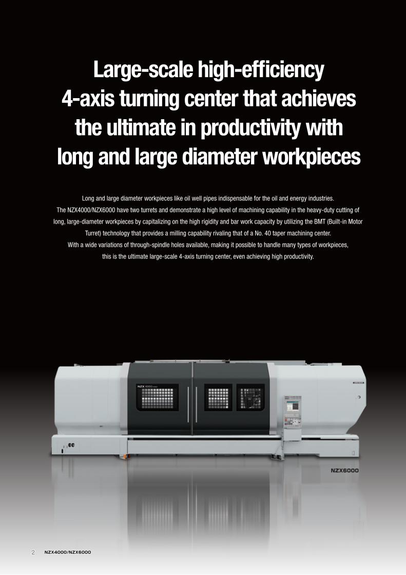
Large-scale high-efficiency 4-axis turning center that achieves
the ultimate in productivity with long and large diameter workpieces
Long and large diameter workpieces like oil well pipes indispensable for the oil and energy industries.
The NZX4000/NZX6000 have two turrets and demonstrate a high level of machining capability in the heavy-duty cutting of
long, large-diameter workpieces by capitalizing on the high rigidity and bar work capacity by utilizing the BMT (Built-in Motor
Turret) technology that provides a milling capability rivaling that of a No. 40 taper machining center.
With a wide variations of through-spindle holes available, making it possible to handle many types of workpieces,
this is the ultimate large-scale 4-axis turning center, even achieving high productivity.
NZX6000
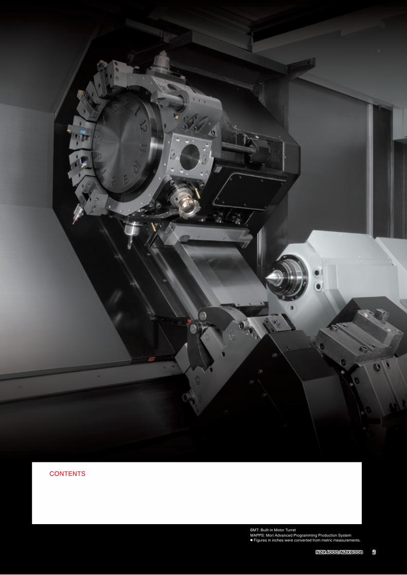
CONTENTS
04 Main features
07 High precision
08 Machining ability
10 Improved workability, Maintenance/Peripheral equipment
12 MAPPS Ⅳ
16 Environmental performance
17 Diagrams
28 Specifications
BMT: Built-in Motor TurretMAPPS: Mori Advanced Programming Production System● Figures in inches were converted from metric measurements.
3NZX4000/NZX6000
4 NZX4000/NZX6000
C-axis
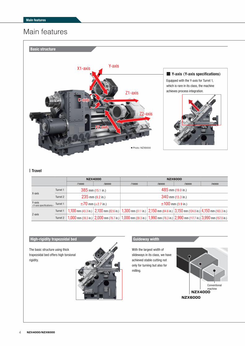
Basic structure
■ Travel
X2-axis
Z2-axis
Z1-axis
Y-axisX1-axis■ Y-axis (Y-axis specifications)Equipped with the Y-axis for Turret 1,
which is rare in its class, the machine
achieves process integration.
Main features
● Photo: NZX6000
High-rigidity trapezoidal bed Guideway width
With the largest width of
slideways in its class, we have
achieved stable cutting not
only for turning but also for
milling.
The basic structure using thick
trapezoidal bed offers high torsional
rigidity.
Conventional machine
NZX4000NZX6000
NZX4000 NZX6000
/1000 /2000 /1000 /2000 /3000 /4000
X-axisTurret 1 385 mm (15.1 in.) 485 mm (19.0 in.)
Turret 2 235 mm (9.2 in.) 340 mm (13.3 in.)
Y-axis <Y-axis specifications> Turret 1 ±70 mm (±2.7 in.) ±100 mm (3.9 in.)
Z-axisTurret 1 1,100 mm (43.3 in.) 2,100 mm (82.6 in.) 1,300 mm (51.1 in.) 2,150 mm (84.6 in.) 3,150 mm (124.0 in.) 4,150 mm (163.3 in.)
Turret 2 1,000 mm (39.3 in.) 2,000 mm (78.7 in.) 1,000 mm (39.3 in.) 1,990 mm (78.3 in.) 2,990 mm (117.7 in.) 3,990 mm (157.0 in.)
Main features
5NZX4000/NZX6000
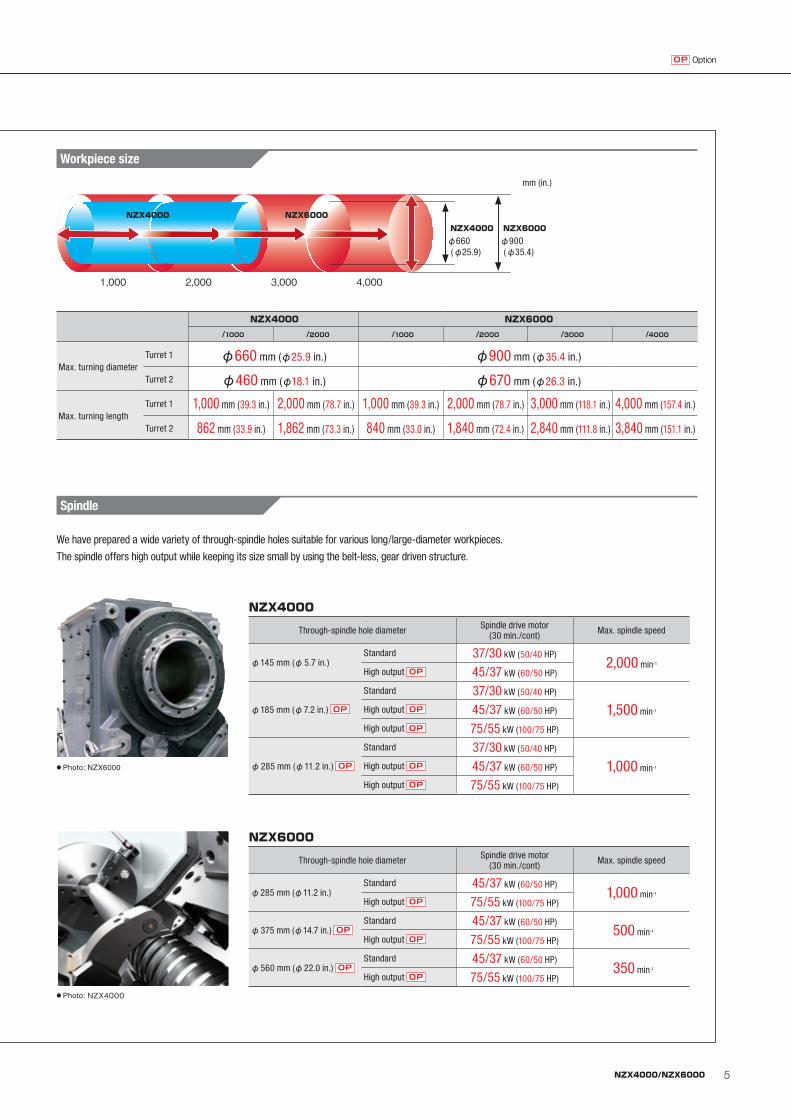
Workpiece size
We have prepared a wide variety of through-spindle holes suitable for various long/large-diameter workpieces.
The spindle offers high output while keeping its size small by using the belt-less, gear driven structure.
Through-spindle hole diameter Spindle drive motor (30 min./cont) Max. spindle speed
φ145 mm (φ5.7 in.)Standard 37/30 kW (50/40 HP)
2,000 min-1
High output OP 45/37 kW (60/50 HP)
φ185 mm (φ7.2 in.) OP
Standard 37/30 kW (50/40 HP)
1,500 min-1High output OP 45/37 kW (60/50 HP)
High output OP 75/55 kW (100/75 HP)
φ285 mm (φ11.2 in.) OP
Standard 37/30 kW (50/40 HP)
1,000 min-1High output OP 45/37 kW (60/50 HP)
High output OP 75/55 kW (100/75 HP)
NZX4000
Through-spindle hole diameter Spindle drive motor (30 min./cont) Max. spindle speed
φ285 mm (φ11.2 in.)Standard 45/37 kW (60/50 HP)
1,000 min-1
High output OP 75/55 kW (100/75 HP)
φ375 mm (φ14.7 in.) OPStandard 45/37 kW (60/50 HP)
500 min-1
High output OP 75/55 kW (100/75 HP)
φ560 mm (φ22.0 in.) OPStandard 45/37 kW (60/50 HP)
350 min-1
High output OP 75/55 kW (100/75 HP)
NZX6000
Spindle
● Photo: NZX6000
mm (in.)
OptionOP
NZX4000 NZX6000
/1000 /2000 /1000 /2000 /3000 /4000
Max. turning diameterTurret 1 φ660 mm (φ25.9 in.) φ900 mm (φ35.4 in.)
Turret 2 φ460 mm (φ18.1 in.) φ670 mm (φ26.3 in.)
Max. turning lengthTurret 1 1,000 mm (39.3 in.) 2,000 mm (78.7 in.) 1,000 mm (39.3 in.) 2,000 mm (78.7 in.) 3,000 mm (118.1 in.) 4,000 mm (157.4 in.)
Turret 2 862 mm (33.9 in.) 1,862 mm (73.3 in.) 840 mm (33.0 in.) 1,840 mm (72.4 in.) 2,840 mm (111.8 in.) 3,840 mm (151.1 in.)
● Photo: NZX4000
1,000 2,000 3,000 4,000
φ660 (φ25.9)
φ900 (φ35.4)
NZX4000 NZX6000
NZX4000 NZX6000
6 NZX4000/NZX6000
Main features
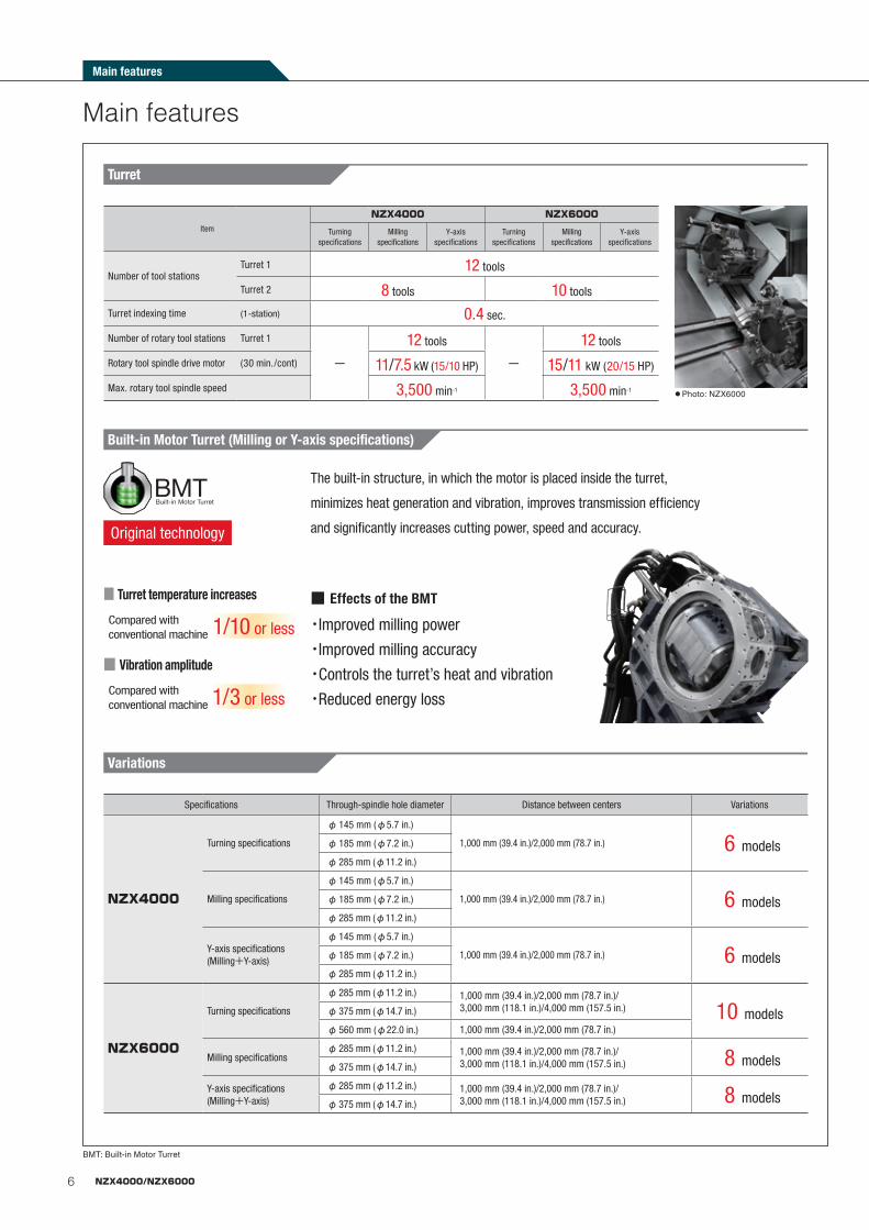
Variations
Built-in Motor Turret (Milling or Y-axis specifications)
■ Turret temperature increases
Compared with conventional machine
■ Vibration amplitude
Compared with conventional machine
1/10 or less
1/3 or less
Original technology
BMT: Built-in Motor Turret
Specifications Through-spindle hole diameter Distance between centers Variations
NZX4000
Turning specifications
φ145 mm (φ5.7 in.)
1,000 mm (39.4 in.)/2,000 mm (78.7 in.) 6 modelsφ185 mm (φ7.2 in.)
φ285 mm (φ11.2 in.)
Milling specifications
φ145 mm (φ5.7 in.)
1,000 mm (39.4 in.)/2,000 mm (78.7 in.) 6 modelsφ185 mm (φ7.2 in.)
φ285 mm (φ11.2 in.)
Y-axis specifications(Milling+Y-axis)
φ145 mm (φ5.7 in.)
1,000 mm (39.4 in.)/2,000 mm (78.7 in.) 6 modelsφ185 mm (φ7.2 in.)
φ285 mm (φ11.2 in.)
NZX6000
Turning specifications
φ285 mm (φ11.2 in.) 1,000 mm (39.4 in.)/2,000 mm (78.7 in.)/3,000 mm (118.1 in.)/4,000 mm (157.5 in.) 10 modelsφ375 mm (φ14.7 in.)
φ560 mm (φ22.0 in.) 1,000 mm (39.4 in.)/2,000 mm (78.7 in.)
Milling specificationsφ285 mm (φ11.2 in.) 1,000 mm (39.4 in.)/2,000 mm (78.7 in.)/
3,000 mm (118.1 in.)/4,000 mm (157.5 in.) 8 modelsφ375 mm (φ14.7 in.)
Y-axis specifications(Milling+Y-axis)
φ285 mm (φ11.2 in.) 1,000 mm (39.4 in.)/2,000 mm (78.7 in.)/3,000 mm (118.1 in.)/4,000 mm (157.5 in.) 8 modelsφ375 mm (φ14.7 in.)
Turret
Item
NZX4000 NZX6000
Turning specifications
Milling specifications
Y-axis specifications
Turning specifications
Milling specifications
Y-axis specifications
Number of tool stationsTurret 1 12 tools
Turret 2 8 tools 10 tools
Turret indexing time (1-station) 0.4 sec.
Number of rotary tool stations Turret 1
ー
12 tools
ー
12 tools
Rotary tool spindle drive motor (30 min./cont) 11/7.5 kW (15/10 HP) 15/11 kW (20/15 HP)
Max. rotary tool spindle speed 3,500 min-1 3,500 min-1● Photo: NZX6000
The built-in structure, in which the motor is placed inside the turret,
minimizes heat generation and vibration, improves transmission efficiency
and significantly increases cutting power, speed and accuracy.
・Improved milling power
・Improved milling accuracy
・Controls the turret’s heat and vibration
・Reduced energy loss
■ Effects of the BMT
Main features
7NZX4000/NZX6000
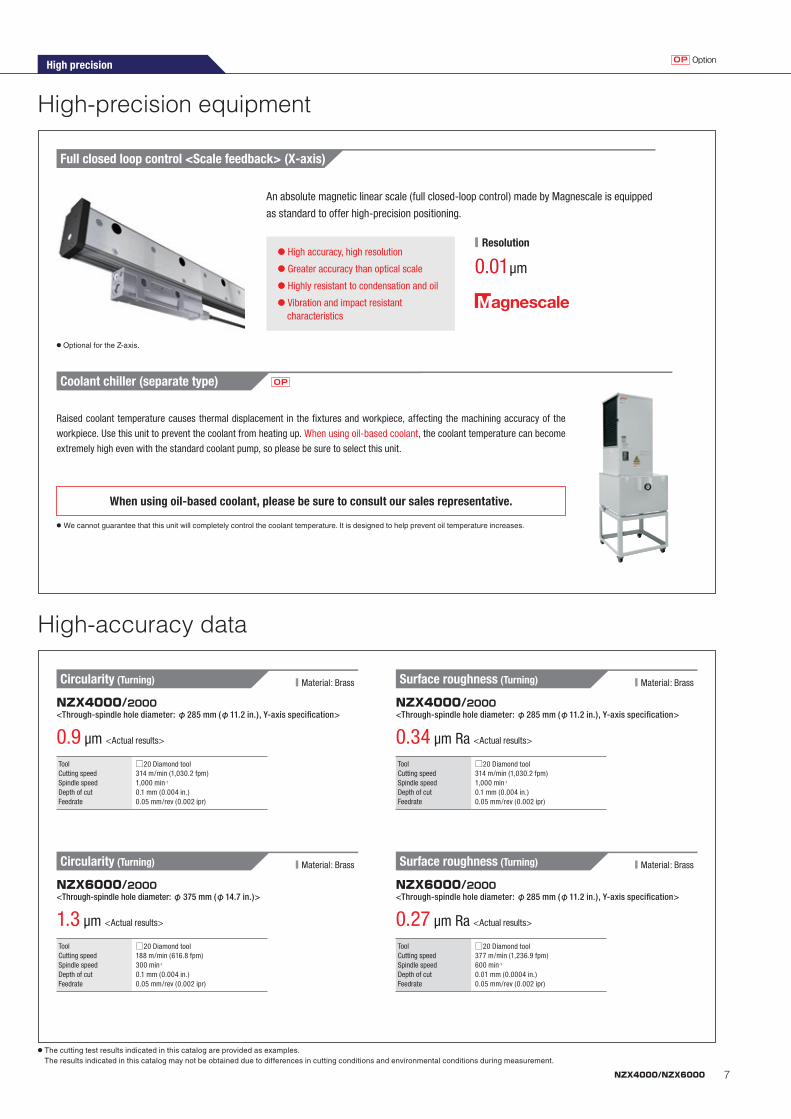
High-accuracy data
High-precision equipment
Full closed loop control <Scale feedback> (X-axis)
● High accuracy, high resolution
● Greater accuracy than optical scale
● Highly resistant to condensation and oil
● Vibration and impact resistant characteristics
0.01 μm
An absolute magnetic linear scale (full closed-loop control) made by Magnescale is equipped
as standard to offer high-precision positioning.
■ Resolution
Circularity (Turning)
Circularity (Turning)
ToolCutting speedSpindle speedDepth of cutFeedrate
□20 Diamond tool188 m/min (616.8 fpm)300 min-1
0.1 mm (0.004 in.)0.05 mm/rev (0.002 ipr)
ToolCutting speedSpindle speedDepth of cutFeedrate
□20 Diamond tool314 m/min (1,030.2 fpm)1,000 min-1
0.1 mm (0.004 in.)0.05 mm/rev (0.002 ipr)
ToolCutting speedSpindle speedDepth of cutFeedrate
□20 Diamond tool377 m/min (1,236.9 fpm)600 min-1
0.01 mm (0.0004 in.)0.05 mm/rev (0.002 ipr)
ToolCutting speedSpindle speedDepth of cutFeedrate
□20 Diamond tool314 m/min (1,030.2 fpm)1,000 min-1
0.1 mm (0.004 in.)0.05 mm/rev (0.002 ipr)
NZX6000/2000<Through-spindle hole diameter: φ375 mm (φ14.7 in.)>
NZX4000/2000<Through-spindle hole diameter: φ285 mm (φ11.2 in.), Y-axis specification>
1.3 μm <Actual results>
0.9 μm <Actual results>
Surface roughness (Turning)
Surface roughness (Turning)
NZX6000/2000<Through-spindle hole diameter: φ285 mm (φ11.2 in.), Y-axis specification>
NZX4000/2000<Through-spindle hole diameter: φ285 mm (φ11.2 in.), Y-axis specification>
0.27 μm Ra <Actual results>
0.34 μm Ra <Actual results>
■ Material: Brass
■ Material: Brass
■ Material: Brass
■ Material: Brass
When using oil-based coolant, please be sure to consult our sales representative.
● We cannot guarantee that this unit will completely control the coolant temperature. It is designed to help prevent oil temperature increases.
Raised coolant temperature causes thermal displacement in the fixtures and workpiece, affecting the machining accuracy of the
workpiece. Use this unit to prevent the coolant from heating up. When using oil-based coolant, the coolant temperature can become
extremely high even with the standard coolant pump, so please be sure to select this unit.
Coolant chiller (separate type) OP
● Optional for the Z-axis.
High precision OptionOP
● The cutting test results indicated in this catalog are provided as examples. The results indicated in this catalog may not be obtained due to differences in cutting conditions and environmental conditions during measurement.
8 NZX4000/NZX6000
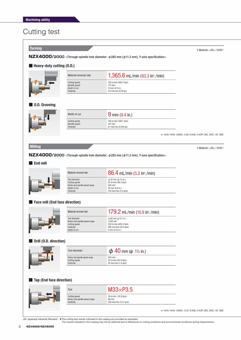
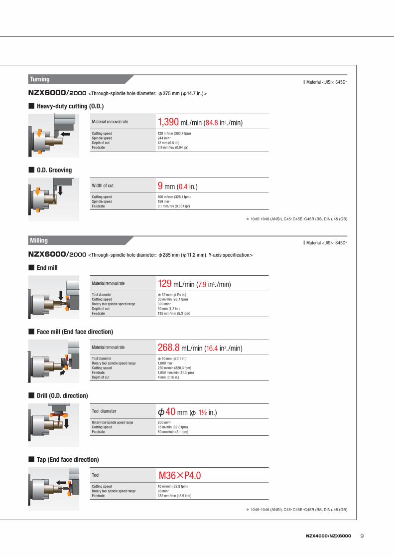
Cutting test
Machining ability
JIS: Japanese Industrial Standard ● The cutting test results indicated in this catalog are provided as examples. The results indicated in this catalog may not be obtained due to differences in cutting conditions and environmental conditions during measurement.
* 1045・1046(ANSI)、C45・C45E・C45R(BS, DIN)、45(GB)
* 1045・1046(ANSI)、C45・C45E・C45R(BS, DIN)、45(GB)
■ Material <JIS>: S45C*
■ Material <JIS>: S45C*
■ Heavy-duty cutting (O.D.)
■ O.D. Grooving
■ End mill
■ Drill (O.D. direction)
■ Tap (End face direction)
■ Face mill (End face direction)
Material removal rate 1,365.6 mL/min (83.3 in3./min)Cutting speedSpindle speedDepth of cutFeedrate
120 m/min (393.7 fpm)172 min-1
12 mm (0.5 in.)0.9 mm/rev (0.04 ipr)
Width of cut 9 mm (0.4 in.)Cutting speedSpindle speedFeedrate
100 m/min (328.1 fpm)107 min-1
0.1 mm/rev (0.004 ipr)
Material removal rate 86.4 mL/min (5.2 in3./min)Tool diameterCutting speedRotary tool spindle speed rangeDepth of cutFeedrate
φ32 mm (φ1¼ in.)30 m/min (98.4 fpm)300 min-1
20 mm (0.8 in.)135 mm/min (5.3 ipm)
Tool diameter φ40 mm (φ 1½ in.)Rotary tool spindle speed rangeCutting speedFeedrate
200 min-1
25 m/min (82.0 fpm)40 mm/min (1.6 ipm)
Tool M33×P3.5Cutting speedRotary tool spindle speed rangeFeedrate
10 m/min (32.8 fpm)96 min-1
336 mm/min (13.2 ipm)
Material removal rate 179.2 mL/min (10.9 in3./min)Tool diameterRotary tool spindle speed rangeCutting speedFeedrateDepth of cut
φ80 mm (φ3.1 in.)1,000 min-1
250 m/min (820.3 fpm)560 mm/min (22.0 ipm)4 mm (0.16 in.)
Turning
Milling
NZX4000/2000 <Through-spindle hole diameter: φ285 mm (φ11.2 mm), Y-axis specification>
NZX4000/2000 <Through-spindle hole diameter: φ285 mm (φ11.2 mm), Y-axis specification>
9NZX4000/NZX6000
* 1045・1046 (ANSI)、C45・C45E・C45R (BS, DIN)、45 (GB)
* 1045・1046 (ANSI)、C45・C45E・C45R (BS, DIN)、45 (GB)
■ Material <JIS>: S45C*
■ Material <JIS>: S45C*
■ Heavy-duty cutting (O.D.)
■ O.D. Grooving
■ End mill
■ Drill (O.D. direction)
■ Tap (End face direction)
■ Face mill (End face direction)
Material removal rate 1,390 mL/min (84.8 in3./min)Cutting speedSpindle speedDepth of cutFeedrate
120 m/min (393.7 fpm)244 min-1
12 mm (0.5 in.)0.9 mm/rev (0.04 ipr)
Width of cut 9 mm (0.4 in.)Cutting speedSpindle speedFeedrate
100 m/min (328.1 fpm)159 min-1
0.1 mm/rev (0.004 ipr)
Material removal rate 129 mL/min (7.9 in3./min)Tool diameterCutting speedRotary tool spindle speed rangeDepth of cutFeedrate
φ32 mm (φ1¼ in.)30 m/min (98.4 fpm)300 min-1
30 mm (1.2 in.)135 mm/min (5.3 ipm)
Tool diameter φ40 mm (φ 1½ in.)Rotary tool spindle speed rangeCutting speedFeedrate
200 min-1
25 m/min (82.0 fpm)80 mm/min (3.1 ipm)
Tool M36×P4.0Cutting speedRotary tool spindle speed rangeFeedrate
10 m/min (32.8 fpm)88 min-1
352 mm/min (13.9 ipm)
Material removal rate 268.8 mL/min (16.4 in3./min)Tool diameterRotary tool spindle speed rangeCutting speedFeedrateDepth of cut
φ80 mm (φ3.1 in.)1,000 min-1
250 m/min (820.3 fpm)1,050 mm/min (41.3 ipm)4 mm (0.16 in.)
Turning
Milling
NZX6000/2000 <Through-spindle hole diameter: φ375 mm (φ14.7 in.)>
NZX6000/2000 <Through-spindle hole diameter: φ285 mm (φ11.2 mm), Y-axis specification>

10 NZX4000/NZX6000
Detachable internal step
Improved workability,Maintenance
OP
The detachable inner step allows easier setups, such as attaching or
removing tool holders and cutting tools to or from the turret.
Bed with a cover
Since the bed is entirely covered, it is
hardly affected by heat from chips at all.
Peripheral equipment
The long boring bar allows long, I.D. boring.
Air chuck (rear)
Air chuck (front)
Work stopper, Centering chuck
Up to two NC steady rests can be installed. The steady rests minimize run-out
during machining of long workpieces, allowing high-precision machining.
OP
The high-accuracy machining can be performed by holding workpieces with the
front and rear chucks.
Specifications
Workpiece material and chip size ○: Suitable -: Not suitable
Steel Cast iron Aluminum, non-ferrous metal
Long Short Powdery Short Long Short Powdery
Hinge type ○ - - - ○ - -
Hinge type+ Drum filter type ○ ○ ○ ○ ○ ○ ○
Magnet scraper type - ○ ○ ○ - - -
Chip size guidelinesShort: chips 50 mm (2.0 in.) or less in length,
bundles of chips φ40 mm (φ1.6 in.) or lessLong: bigger than the above
● The options table shows the general options when using coolant. Changes may be necessary if you are not using coolant, or depending on the amount of coolant, compatibility with machines, or the specifications required.
● Please select a chip conveyor to suit the shape of your chips. When using special or difficult-to-cut material (chip hardness HRC45 or higher), please consult our sales representative.
● Chip conveyors are available in various types for handling chips of different shape and material. For details, please consult our sales representative.
External chip conveyor OP
OPLong boring bar specifications </2000, /3000, /4000>
Steady rests specifications
OPMachining of oil well pipes <Air chuck (Front, Rear), Centering chuck>
● Long boring bar sizes for the NZX4000 and the NZX6000 differ. NZX4000: A diameter of φ90 mm (φ3.5 in.) and a length of up to 1,000 mm (39.3 in.) NZX6000: A diameter of φ130 (φ5.1 in.) mm and a length of up to 1,300 mm (51.1 in.)
Improved workability, Maintenance Peripheral equipment
11NZX4000/NZX6000
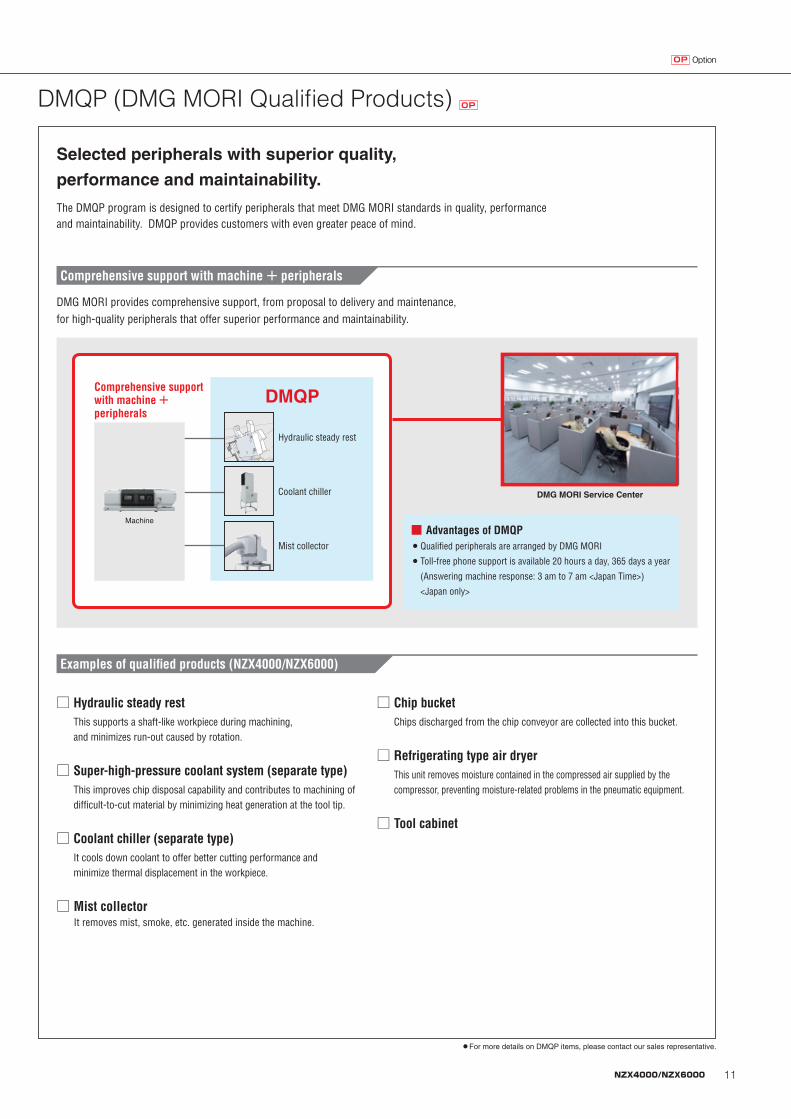
DMQP (DMG MORI Qualified Products) OP
● For more details on DMQP items, please contact our sales representative.
Examples of qualified products (NZX4000/NZX6000)
□ �Hydraulic steady rest�This supports a shaft-like workpiece during machining, and minimizes run-out caused by rotation.
□ ��Coolant chiller (separate type)�It cools down coolant to offer better cutting performance and minimize thermal displacement in the workpiece.
□ �Super-high-pressure coolant system (separate type) This improves chip disposal capability and contributes to machining of difficult-to-cut material by minimizing heat generation at the tool tip.
□ �Tool cabinet
□ �Refrigerating type air dryer�This unit removes moisture contained in the compressed air supplied by the compressor, preventing moisture-related problems in the pneumatic equipment.
□ �Chip bucket�Chips discharged from the chip conveyor are collected into this bucket.
Comprehensive support with machine + peripherals
DMG MORI Service Center
Hydraulic steady rest
Coolant chiller
Mist collector
Machine
DMQP
□ �Mist collector�It removes mist, smoke, etc. generated inside the machine.
OptionOP
The DMQP program is designed to certify peripherals that meet DMG MORI standards in quality, performance and maintainability. DMQP provides customers with even greater peace of mind.
Selected peripherals with superior quality,
performance and maintainability.
DMG MORI provides comprehensive support, from proposal to delivery and maintenance, for high-quality peripherals that offer superior performance and maintainability.
Comprehensive support with machine + peripherals
■ Advantages of DMQP● Qualified peripherals are arranged by DMG MORI● �Toll-free phone support is available 20 hours a day, 365 days a year
(Answering machine response: 3 am to 7 am <Japan Time>)
<Japan only>
NZX4060_EB01V_FORM.indd 1 2019/06/04 13:36
OptionOP
12 NZX4000/NZX6000
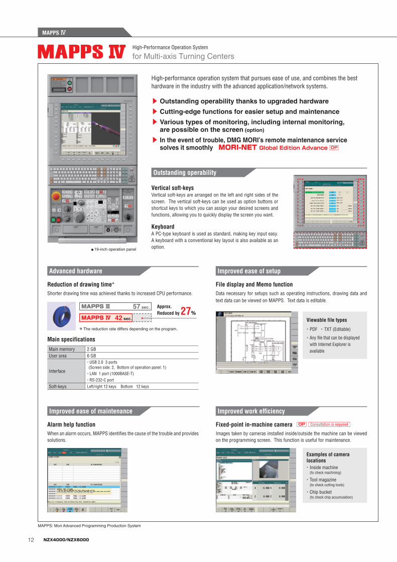
MAPPS Ⅳ
for Multi-axis Turning CentersHigh-Performance Operation System
● 19-inch operation panel
High-performance operation system that pursues ease of use, and combines the best hardware in the industry with the advanced application/network systems.
▶ Outstanding operability thanks to upgraded hardware
▶ Cutting-edge functions for easier setup and maintenance
▶ Various types of monitoring, including internal monitoring, are possible on the screen (option)
▶ In the event of trouble, DMG MORI’s remote maintenance service solves it smoothly MORI-NET Global Edition Advance OP
Reduction of drawing time*
Main specifications
Shorter drawing time was achieved thanks to increased CPU performance.
Main memory 2 GBUser area 6 GB
Interface
・ USB 2.0 3 ports (Screen side: 2, Bottom of operation panel: 1)
・LAN 1 port (1000BASE-T)・RS-232-C port
Soft-keys Left/right 12 keys Bottom 12 keys
Advanced hardware
Approx. Reduced by 27%
MAPPS Ⅲ 57 sec.
42 sec.MAPPS Ⅳ
MAPPS: Mori Advanced Programming Production System
* The reduction rate differs depending on the program.
Vertical soft-keys
Keyboard
Vertical soft-keys are arranged on the left and right sides of the screen. The vertical soft-keys can be used as option buttons or shortcut keys to which you can assign your desired screens and functions, allowing you to quickly display the screen you want.
A PC-type keyboard is used as standard, making key input easy. A keyboard with a conventional key layout is also available as an option.
Outstanding operability
File display and Memo functionData necessary for setups such as operating instructions, drawing data and text data can be viewed on MAPPS. Text data is editable.
Improved ease of setup
Viewable file types
・ PDF ・ TXT (Editable)
・ Any file that can be displayed with Internet Explorer is available
Fixed-point in-machine cameraImages taken by cameras installed inside/outside the machine can be viewed on the programming screen. This function is useful for maintenance.
Examples of camera locations・ Inside machine
(to check machining)
・ Tool magazine (to check cutting tools)
・ Chip bucket (to check chip accumulation)
Consultation is requiredOP
Improved work efficiency
Alarm help functionWhen an alarm occurs, MAPPS identifies the cause of the trouble and provides solutions.
Improved ease of maintenance
NZX4060_EB01V_FORM.indd 2 2019/06/04 13:36
MAPPS Ⅳ
13NZX4000/NZX6000
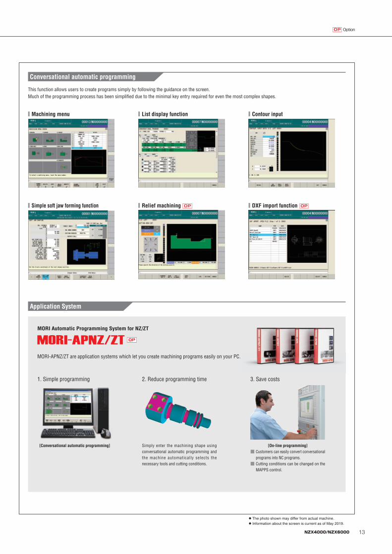
● The photo shown may differ from actual machine.● Information about the screen is current as of May 2019.
OptionOP
Application System
MORI-APNZ/ZT are application systems which let you create machining programs easily on your PC.
MORI Automatic Programming System for NZ/ZT
1. Simple programming
[Conversational automatic programming]
2. Reduce programming time
Simply enter the machining shape using conversational automatic programming and the machine automatically selects the necessary tools and cutting conditions.
3. Save costs
[On-line programming]■ �Customers can easily convert conversational
programs into NC programs.■ �Cutting conditions can be changed on the
MAPPS control.
■�Simple soft jaw forming function
■�Contour input
■�DXF import function� OP
■�List display function
■�Relief machining� OP
This function allows users to create programs simply by following the guidance on the screen.Much of the programming process has been simplified due to the minimal key entry required for even the most complex shapes.
Conversational automatic programming
■�Machining menu
OP
NZX4060_EB01V_FORM.indd 3 2019/06/04 13:36
OptionOP
14 NZX4000/NZX6000
MAPPS Ⅳ
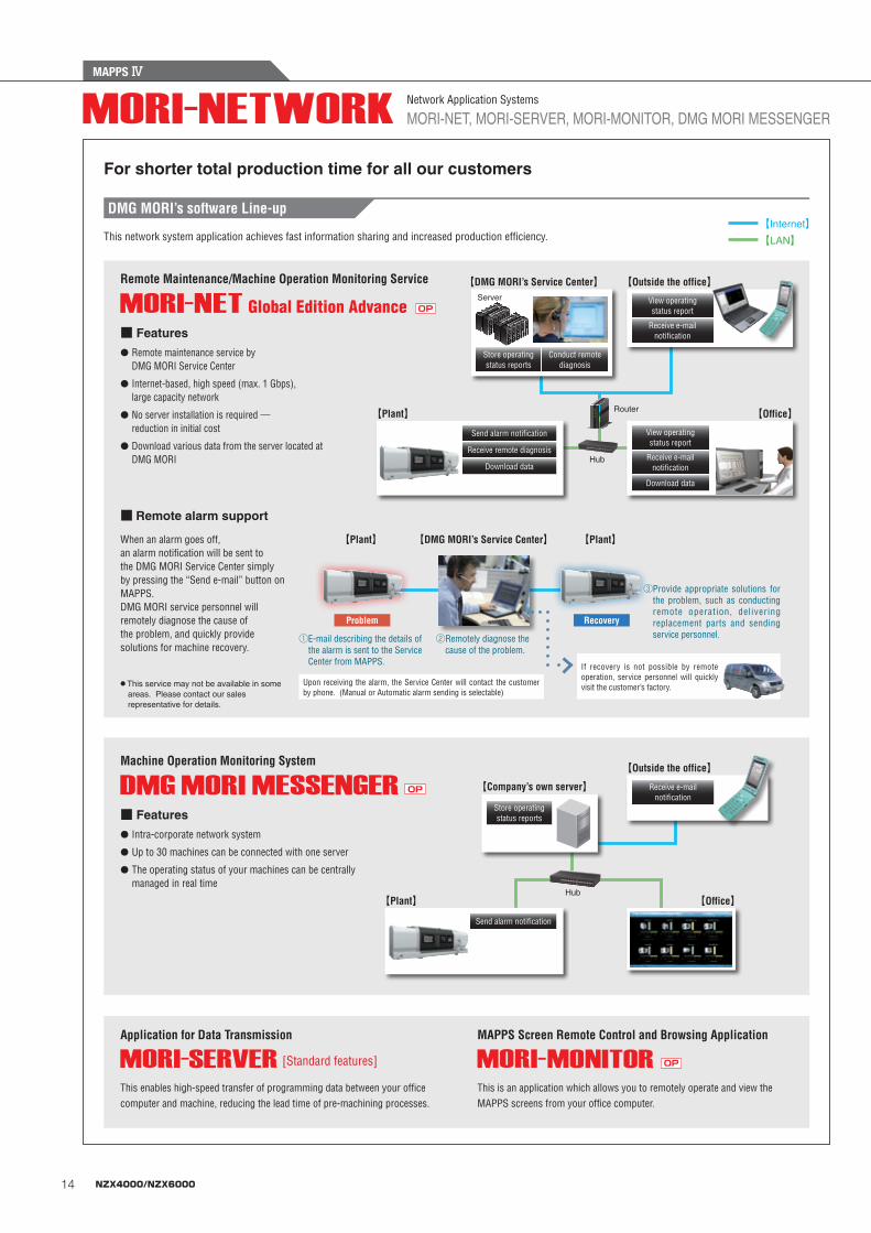
This is an application which allows you to remotely operate and view the MAPPS screens from your office computer.
This enables high-speed transfer of programming data between your office computer and machine, reducing the lead time of pre-machining processes.
DMG MORI’s software Line-up
For shorter total production time for all our customers
This network system application achieves fast information sharing and increased production efficiency.
Remote Maintenance/Machine Operation Monitoring Service
Machine Operation Monitoring System
Application for Data Transmission MAPPS Screen Remote Control and Browsing Application
【Plant】
【Plant】
[Standard features]
Receive e-mail notification
View operating status report
Receive e-mail notification
【DMG MORI’s Service Center】
【Company’s own server】
Server
Hub
Router
● Remote maintenance service by DMG MORI Service Center
● �Internet-based, high speed (max. 1 Gbps), large capacity network
● �No server installation is required ― reduction in initial cost
● �Download various data from the server located at DMG MORI
● Intra-corporate network system
● Up to 30 machines can be connected with one server
● The operating status of your machines can be centrally managed in real time
■ Features
■ Features
【Office】
【Outside the office】
【Outside the office】
Receive remote diagnosis
Download data
Download data
Send alarm notification
Hub
OP
OP
Store operating status reports
Send alarm notification
【Office】
■ Remote alarm support
When an alarm goes off, an alarm notification will be sent to the DMG MORI Service Center simply by pressing the “Send e-mail” button on MAPPS. DMG MORI service personnel will remotely diagnose the cause of the problem, and quickly provide solutions for machine recovery.
【Plant】 【Plant】【DMG MORI’s Service Center】
① E-mail describing the details of the alarm is sent to the Service Center from MAPPS.
② Remotely diagnose the cause of the problem.
③ Provide appropriate solutions for the problem, such as conducting remote operation, delivering replacement parts and sending service personnel.
Problem Recovery
Upon receiving the alarm, the Service Center will contact the customer by phone. (Manual or Automatic alarm sending is selectable)
If recovery is not possible by remote operation, service personnel will quickly visit the customer’s factory.● �This service may not be available in some
areas. Please contact our sales representative for details.
Store operating status reports
Conduct remote diagnosis
View operating status report
Receive e-mail notification
MORI-NET, MORI-SERVER, MORI-MONITOR, DMG MORI MESSENGERNetwork Application Systems
【Internet】 【LAN】
OP
NETWORK_E01_cs5.indd 1 2018/01/31 11:27
OptionOP
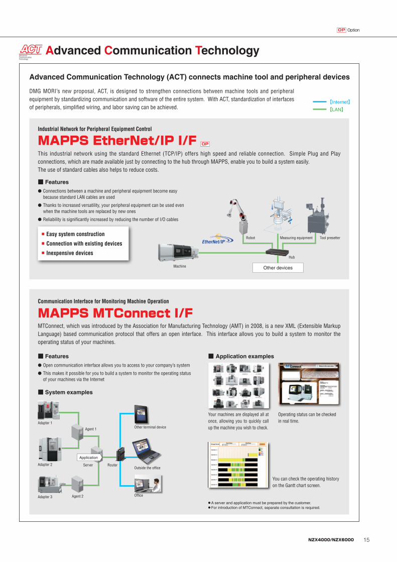
DMG MORI’s new proposal, ACT, is designed to strengthen connections between machine tools and peripheral equipment by standardizing communication and software of the entire system. With ACT, standardization of interfaces of peripherals, simplified wiring, and labor saving can be achieved.
This industrial network using the standard Ethernet (TCP/IP) offers high speed and reliable connection. Simple Plug and Play connections, which are made available just by connecting to the hub through MAPPS, enable you to build a system easily.The use of standard cables also helps to reduce costs.
MTConnect, which was introduced by the Association for Manufacturing Technology (AMT) in 2008, is a new XML (Extensible Markup Language) based communication protocol that offers an open interface. This interface allows you to build a system to monitor the operating status of your machines.
Advanced Communication Technology
MAPPS EtherNet/IP I/F OP
MAPPS MTConnect I/F
Advanced Communication Technology (ACT) connects machine tool and peripheral devices
■ Easy system construction■ Connection with existing devices■ Inexpensive devices
You can check the operating history on the Gantt chart screen.
● �Connections between a machine and peripheral equipment become easy because standard LAN cables are used
● �Thanks to increased versatility, your peripheral equipment can be used even when the machine tools are replaced by new ones
● �Reliability is significantly increased by reducing the number of I/O cables
● �Open communication interface allows you to access to your company’s system
● �This makes it possible for you to build a system to monitor the operating status of your machines via the Internet
■ Features
■ Features
■ System examples
Operating status can be checked in real time.
Your machines are displayed all at once, allowing you to quickly call up the machine you wish to check.
■ Application examples
Industrial Network for Peripheral Equipment Control
Communication Interface for Monitoring Machine Operation
● �A server and application must be prepared by the customer.● For introduction of MTConnect, separate consultation is required.
【Internet】 【LAN】
Other devices
Measuring equipment Tool presetter
Machine
Hub
Robot
Adapter 1
ServerAdapter 2
Adapter 3
Outside the office
Office
Other terminal deviceAgent 1
Agent 2
Application
Router
NETWORK_E01_cs5.indd 2 2018/01/31 11:27
MAPPS Ⅳ
NZX4060_EB01V_FORM.indd 4 2019/06/04 13:36
MAPPS Ⅳ
15NZX4000/NZX6000
MAPPS Ⅳ
This is an application which allows you to remotely operate and view the MAPPS screens from your office computer.
This enables high-speed transfer of programming data between your office computer and machine, reducing the lead time of pre-machining processes.
DMG MORI’s software Line-up
For shorter total production time for all our customers
This network system application achieves fast information sharing and increased production efficiency.
Remote Maintenance/Machine Operation Monitoring Service
Machine Operation Monitoring System
Application for Data Transmission MAPPS Screen Remote Control and Browsing Application
【Plant】
【Plant】
[Standard features]
Receive e-mail notification
View operating status report
Receive e-mail notification
【DMG MORI’s Service Center】
【Company’s own server】
Server
Hub
Router
● Remote maintenance service by DMG MORI Service Center
● �Internet-based, high speed (max. 1 Gbps), large capacity network
● �No server installation is required ― reduction in initial cost
● �Download various data from the server located at DMG MORI
● Intra-corporate network system
● Up to 30 machines can be connected with one server
● The operating status of your machines can be centrally managed in real time
■ Features
■ Features
【Office】
【Outside the office】
【Outside the office】
Receive remote diagnosis
Download data
Download data
Send alarm notification
Hub
OP
OP
Store operating status reports
Send alarm notification
【Office】
■ Remote alarm support
When an alarm goes off, an alarm notification will be sent to the DMG MORI Service Center simply by pressing the “Send e-mail” button on MAPPS. DMG MORI service personnel will remotely diagnose the cause of the problem, and quickly provide solutions for machine recovery.
【Plant】 【Plant】【DMG MORI’s Service Center】
① E-mail describing the details of the alarm is sent to the Service Center from MAPPS.
② Remotely diagnose the cause of the problem.
③ Provide appropriate solutions for the problem, such as conducting remote operation, delivering replacement parts and sending service personnel.
Problem Recovery
Upon receiving the alarm, the Service Center will contact the customer by phone. (Manual or Automatic alarm sending is selectable)
If recovery is not possible by remote operation, service personnel will quickly visit the customer’s factory.● �This service may not be available in some
areas. Please contact our sales representative for details.
Store operating status reports
Conduct remote diagnosis
View operating status report
Receive e-mail notification
MORI-NET, MORI-SERVER, MORI-MONITOR, DMG MORI MESSENGERNetwork Application Systems
【Internet】 【LAN】
OP
NETWORK_E01_cs5.indd 1 2018/01/31 11:27
OptionOP
DMG MORI’s new proposal, ACT, is designed to strengthen connections between machine tools and peripheral equipment by standardizing communication and software of the entire system. With ACT, standardization of interfaces of peripherals, simplified wiring, and labor saving can be achieved.
This industrial network using the standard Ethernet (TCP/IP) offers high speed and reliable connection. Simple Plug and Play connections, which are made available just by connecting to the hub through MAPPS, enable you to build a system easily.The use of standard cables also helps to reduce costs.
MTConnect, which was introduced by the Association for Manufacturing Technology (AMT) in 2008, is a new XML (Extensible Markup Language) based communication protocol that offers an open interface. This interface allows you to build a system to monitor the operating status of your machines.
Advanced Communication Technology
MAPPS EtherNet/IP I/F OP
MAPPS MTConnect I/F
Advanced Communication Technology (ACT) connects machine tool and peripheral devices
■ Easy system construction■ Connection with existing devices■ Inexpensive devices
You can check the operating history on the Gantt chart screen.
● �Connections between a machine and peripheral equipment become easy because standard LAN cables are used
● �Thanks to increased versatility, your peripheral equipment can be used even when the machine tools are replaced by new ones
● �Reliability is significantly increased by reducing the number of I/O cables
● �Open communication interface allows you to access to your company’s system
● �This makes it possible for you to build a system to monitor the operating status of your machines via the Internet
■ Features
■ Features
■ System examples
Operating status can be checked in real time.
Your machines are displayed all at once, allowing you to quickly call up the machine you wish to check.
■ Application examples
Industrial Network for Peripheral Equipment Control
Communication Interface for Monitoring Machine Operation
● �A server and application must be prepared by the customer.● For introduction of MTConnect, separate consultation is required.
【Internet】 【LAN】
Other devices
Measuring equipment Tool presetter
Machine
Hub
Robot
Adapter 1
ServerAdapter 2
Adapter 3
Outside the office
Office
Other terminal deviceAgent 1
Agent 2
Application
Router
NETWORK_E01_cs5.indd 2 2018/01/31 11:27
OptionOP
NZX4060_EB01V_FORM.indd 5 2019/06/04 13:36
OptionOP
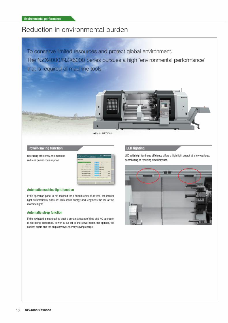
To conserve limited resources and protect global environment.The NZX4000/NZX6000 Series pursues a high "environmental performance"
that is required of machine tools.
16 NZX4000/NZX6000
Reduction in environmental burden
LED with high luminous efficiency offers a high light output at a low wattage,
contributing to reducing electricity use.
If the operation panel is not touched for a certain amount of time, the interior light automatically turns off. This saves energy and lengthens the life of the machine lights.
If the keyboard is not touched after a certain amount of time and NC operation is not being performed, power is cut off to the servo motor, the spindle, the coolant pump and the chip conveyor, thereby saving energy.
Automatic machine light function
Automatic sleep function
Operating efficiently, the machine
reduces power consumption.
Power-saving function LED lighting
● Photo: NZX4000
Environmental performance
17NZX4000/NZX6000
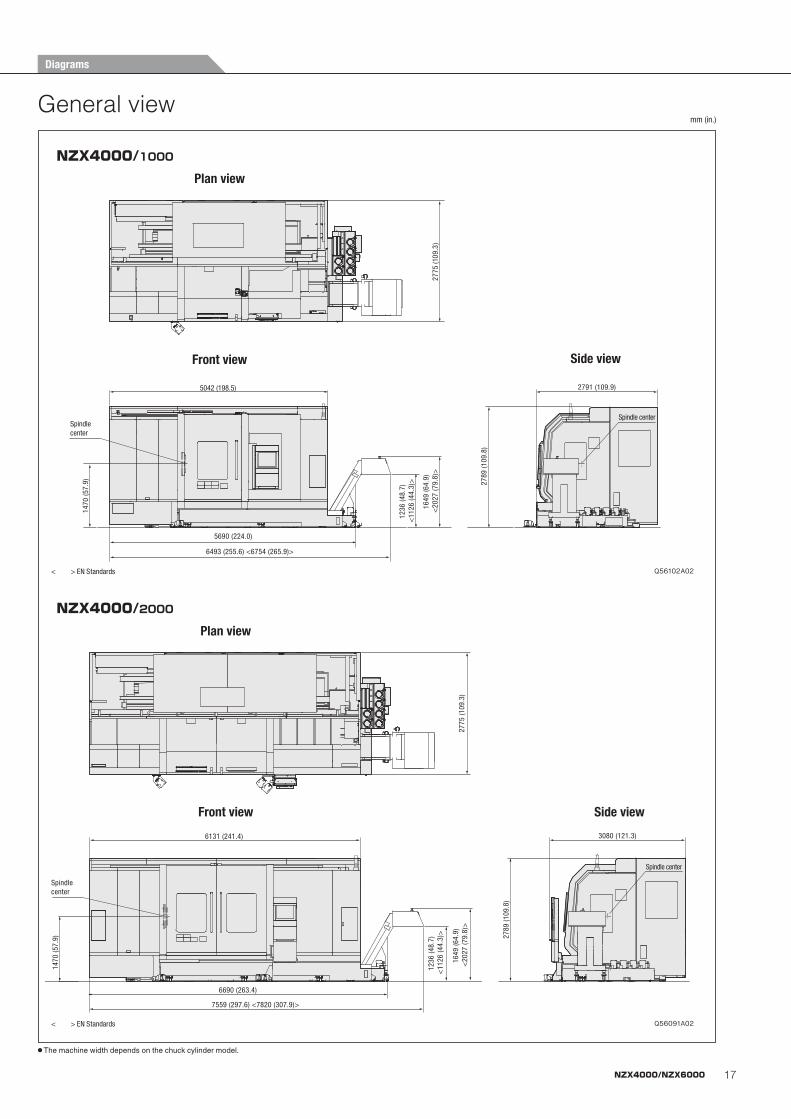
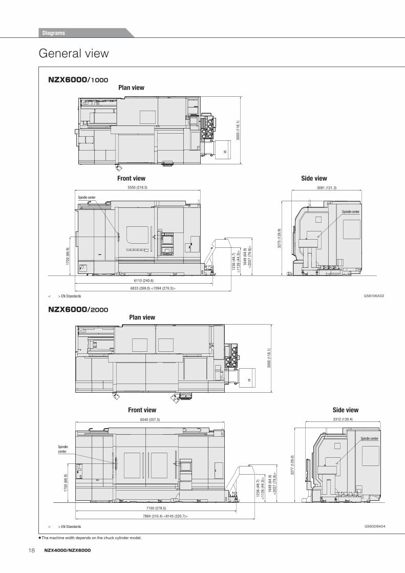
General viewmm (in.)
● The machine width depends on the chuck cylinder model.
Spindle center
2791 (109.9)5042 (198.5)
6493 (255.6) <6754 (265.9)>
5690 (224.0)
1236
(48.
7)
<11
26 (4
4.3)
>
1649
(64.
9) <
2027
(79.
8)>
1470
(57.
9)
Spindle center
2789
(109
.8)
2775
(109
.3)
NZX4000/1000
Front view Side view
Q56102A02
Plan view
< > EN Standards
Spindle center
2791 (109.9)5042 (198.5)
6493 (255.6) <6754 (265.9)>
5690 (224.0)
1236
(48.
7)
<11
26 (4
4.3)
>
1649
(64.
9) <
2027
(79.
8)>
1470
(57.
9)
Spindle center
2789
(109
.8)
2775
(109
.3)
Spindle center
2791 (109.9)5042 (198.5)
6493 (255.6) <6754 (265.9)>
5690 (224.0)
1236
(48.
7)
<11
26 (4
4.3)
>
1649
(64.
9) <
2027
(79.
8)>
1470
(57.
9)
Spindle center
2789
(109
.8)
2775
(109
.3)
Spindle center
7559 (297.6) <7820 (307.9)>
6690 (263.4)
1470
(57.
9)
Spindle center
6131 (241.4)
1236
(48.
7) <
1126
(44.
3)>
1649
(64.
9) <
2027
(79.
8)>
2789
(109
.8)
3080 (121.3)
2775
(109
.3)
NZX4000/2000
Front view Side view
Q56091A02
Plan view
< > EN Standards
Spindle center
7559 (297.6) <7820 (307.9)>
6690 (263.4)
1470
(57.
9)
Spindle center
6131 (241.4)
1236
(48.
7) <
1126
(44.
3)>
1649
(64.
9) <
2027
(79.
8)>
2789
(109
.8)
3080 (121.3)
2775
(109
.3)
Spindle center
7559 (297.6) <7820 (307.9)>
6690 (263.4)
1470
(57.
9)
Spindle center
6131 (241.4)
1236
(48.
7) <
1126
(44.
3)>
1649
(64.
9) <
2027
(79.
8)>
2789
(109
.8)
3080 (121.3)
2775
(109
.3)
Diagrams
18 NZX4000/NZX6000
General view
Spindle center
Spindle center
1700
(66.
9)
6833 (269.0) <7094 (279.3)>
6110 (240.6)
5550 (218.5) 3081 (121.3)
3275
(128
.9)
3000
(118
.1)
1236
(48.
7)<
1126
(44.
3)>
1649
(64.
9)<
2027
(79.
8)>
NZX6000/1000
Front view Side view
Q56106A02
Plan view
< > EN Standards
Spindle center
Spindle center
1700
(66.
9)
6833 (269.0) <7094 (279.3)>
6110 (240.6)
5550 (218.5) 3081 (121.3)
3275
(128
.9)
3000
(118
.1)
1236
(48.
7)<
1126
(44.
3)>
1649
(64.
9)<
2027
(79.
8)>
Spindle center
Spindle center
1700
(66.
9)
6833 (269.0) <7094 (279.3)>
6110 (240.6)
5550 (218.5) 3081 (121.3)
3275
(128
.9)
3000
(118
.1)
1236
(48.
7)<
1126
(44.
3)>
1649
(64.
9)<
2027
(79.
8)>
1236
(48.
7)<
1126
(44.
3)>
7100 (279.5)
Spindle center
1649
(64.
9)<
2027
(79.
8)>
3000
(118
.1)
6540 (257.5)
1700
(66.
9)
7884 (310.4) <8145 (320.7)>
Spindle center
3277
(129
.0)
3312 (130.4)
NZX6000/2000
Front view Side view
Q56009A04
Plan view
< > EN Standards
1236
(48.
7)<
1126
(44.
3)>
7100 (279.5)
Spindle center
1649
(64.
9)<
2027
(79.
8)>
3000
(118
.1)
6540 (257.5)
1700
(66.
9)
7884 (310.4) <8145 (320.7)>
Spindle center
3277
(129
.0)
3312 (130.4)
1236
(48.
7)<
1126
(44.
3)>
7100 (279.5)
Spindle center
1649
(64.
9)<
2027
(79.
8)>
3000
(118
.1)
6540 (257.5)
1700
(66.
9)
7884 (310.4) <8145 (320.7)>
Spindle center
3277
(129
.0)
3312 (130.4)
Diagrams
● The machine width depends on the chuck cylinder model.
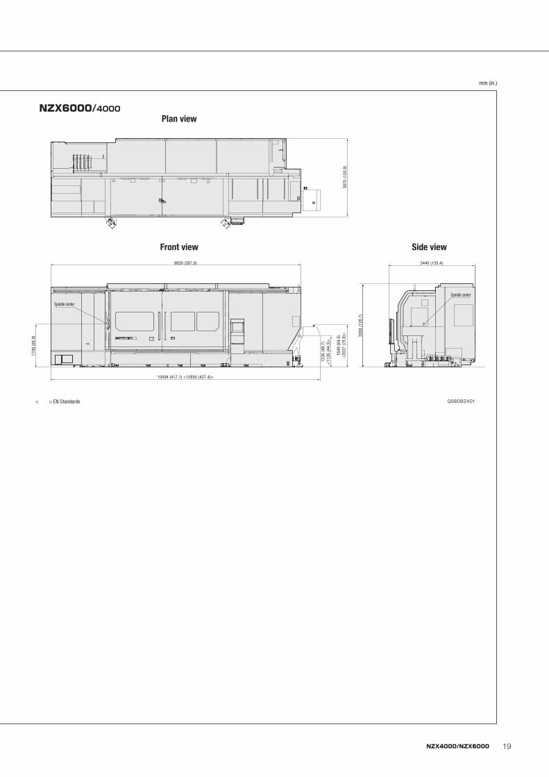
19NZX4000/NZX6000
mm (in.)
3070
(120
.9)
1700
(66.
9)
10594 (417.1) <10855 (427.4)>
9830 (387.0)
Spindle center
1649
(64.
9)<
2027
(79.
8)>
1236
(48.
7)<
1126
(44.
3)>
3440 (135.4)
3268
(128
.7)
Spindle center
NZX6000/4000
Front view Side view
Q56082A01
3070
(120
.9)
1700
(66.
9)
10594 (417.1) <10855 (427.4)>
9830 (387.0)
Spindle center
1649
(64.
9)<
2027
(79.
8)>
1236
(48.
7)<
1126
(44.
3)>
3440 (135.4)
3268
(128
.7)
Spindle center
3070
(120
.9)
1700
(66.
9)
10594 (417.1) <10855 (427.4)>
9830 (387.0)
Spindle center
1649
(64.
9)<
2027
(79.
8)>
1236
(48.
7)<
1126
(44.
3)>
3440 (135.4)
3268
(128
.7)
Spindle center
Plan view
< > EN Standards
20 NZX4000/NZX6000
Spindle speed (min-1)
Outp
ut (k
W)
Torq
ue (N・
m)
First range T=7021 N・m (5178.4 ft・lbf) <30 min.>
First range T=5328.8 N・m (3930.3 ft・lbf) <cont>
Second range T=2889.7 N・m (2131.3 ft・lbf) <30 min.>
Second range T=2375.9 N・m (1,752.4 ft・lbf) <cont>
100000 100
10
1
10000
1000
1001 10 100 600.0 1000 1500
1395.6335.5 (Second range winding change-over point)
First range
First rangeSecond range
Second range
45 kW (60 HP) (30 min.)37 kW (50 HP) (cont) 41.87 kW (55.8 HP) (30 min.)
34.42 kW (45.9 HP) (cont)
T=716.2 N・m (528.2 ft・lbf) <30 min.>
T=588.9 N・m (434.3 ft・lbf) <cont>
T=307.9 N・m (227.1 ft・lbf) <30 min.>
T=253.2 N・m (186.8 ft・lbf) <cont>
T=266.5 N・m (196.6 ft・lbf) <30 min.>
T=219.2 N・m (161.7 ft・lbf) <cont>
149.6 (First range winding change-over point)
61.266.3
148.7137.3
T=177 N・m (130.5 ft・lbf) T=215 N・m (158.6 ft・lbf)
37 kW (50 HP) 45 kW (60 HP)
1069
100000
10000
1000
1001 10
64
70
100
152 (Low speed winding switching speed)
216
234
6521000
2000
100
10
1
Spindle speed (min-1)
Outp
ut (k
W)
Torq
ue (N・
m)
T=659 N・m (486.1 ft・lbf) <30 min.>
T=542 N・m (399.8 ft・lbf) <cont>
High speed T=1990 N・m (1467.7 ft・lbf) <30 min.>
Low speed
Low speed High speed
High speed510 (High speed winding switching speed)
High speed T=1510 N・m (1113.7 ft・lbf) <cont>
Low speed T=5084 N・m (3749.8 ft・lbf) <cont>
Low speed T=6699 N・m (4940.9 ft・lbf) <30 min.>
9801069
282
567 (High speed winding switching speed)
1001 10 100
1000
100000
10000
2000
Spindle speed (min-1)
Torq
ue (N・m
)
Low speed
Low speed
High speed T=1253 N・m (924.2 ft・lbf) <30 min.>
High speed T=1016 N・m (749.4 ft・lbf) <cont>
High speed
T=143 N・m (105.5 ft・lbf)
T=177 N・m (130.5 ft・lbf)
1
10
100
High speed
T=292 N・m (215.4 ft・lbf)
T=361 N・m (266.3 ft・lbf)
37 kW (50 HP)30 kW (40 HP)
1000
Outp
ut(k
W)
168(Low speed winding switching speed)
Low speed T=4219 N・m (3111.8 ft・lbf) <30 min.>
Low speed T=3421 N・m (2523.2 ft・lbf) <cont>
84
Spindle speed (min-1)
Outp
ut (k
W)
Torq
ue (N・
m)
High speed T=1972 N・m (1454.5 ft・lbf) <30 min.>
High speed T=1599 N・m (1179.4 ft・lbf) <cont>
100000 100
10
1
10000
1000
1001 10 100 1500
1020360 (High speed winding switching speed)
Low speed
Low speed High speed
High speed
37 kW (50 HP)
30 kW (40 HP)
T=378 N・m (278.8 ft・lbf)
T=306 N・m (225.7 ft・lbf)
T=236 N・m (174.1 ft・lbf)T=191 N・m (140.9 ft・lbf)
161 (Low speed winding switching speed)
80 179 9351000
Low speed T=3585 N・m (2644.2 ft・lbf) <cont>
Low speed T=4422 N・m (3261.5 ft・lbf) <30 min.>
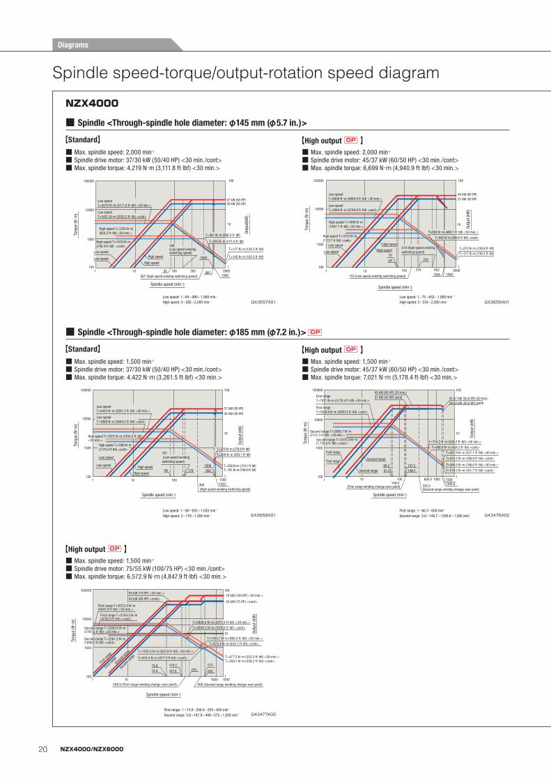
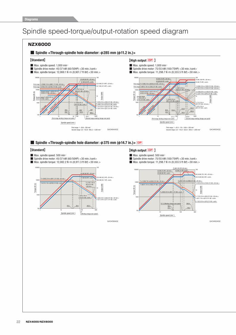
Spindle speed-torque/output-rotation speed diagram
NZX4000
■ Spindle <Through-spindle hole diameter: φ145 mm (φ5.7 in.)>
■ Max. spindle speed: 1,500 min-1
■ Spindle drive motor: 75/55 kW (100/75 HP) <30 min./cont>■ Max. spindle torque: 6,572.9 N・m (4,847.9 ft·lbf) <30 min.>
Spindle speed (min-1)
Out
put (
kW)
Torq
ue (N・
m)
74.8 255 600167.8
572
15001000101
179.279.9
100
1000
10000
100000
1
10
100
First range T=6572.9 N・m (4847.9 ft・lbf) <30 min.>
First range T=5744.5 N・m (4236.9 ft・lbf) <cont>
Second range T=2930.6 N・m (2161.5 ft・lbf) <30 min.>
Second range T=2561.3 N・m (1889.1 ft・lbf) <cont>
55 kW (75 HP) <30 min.>
45 kW (60 HP) <cont>55 kW (75 HP) <cont>
75 kW (100 HP) <30 min.>
T=1252.2 N・m (923.6 ft・lbf) <30 min.>
T=918.3 N・m (677.3 ft・lbf) <cont> T=477.5 N・m (352.2 ft・lbf) <30 min.>T=350.1 N・m (258.2 ft・lbf) <cont>
T=875.4 N・m (645.7 ft・lbf) <cont>
T=1193.7 N・m (880.4 ft・lbf) <30 min.>
T=2059.5 N・m (1519.0 ft・lbf) <cont>
T=2808.4 N・m (2071.4 ft・lbf) <30 min.>
208.6 (First range winding change-over point) 468 (Second range winding change-over point)
Secon
d ran
ge
Secon
d ran
ge
First
range
First
range
【High output OP 】
First range: 1 – 74.8 – 208.6 – 255 – 600 min-1
Second range: 3.8 – 167.8 – 468 – 572 – 1,500 min-1
■ Max. spindle speed: 1,500 min-1
■ Spindle drive motor: 37/30 kW (50/40 HP) <30 min./cont>■ Max. spindle torque: 4,422 N・m (3,261.5 ft·lbf) <30 min.>
■ Max. spindle speed: 1,500 min-1
■ Spindle drive motor: 45/37 kW (60/50 HP) <30 min./cont>■ Max. spindle torque: 7,021 N・m (5,178.4 ft·lbf) <30 min.>
■ Spindle <Through-spindle hole diameter: φ185 mm (φ7.2 in.)> OP
【Standard】 【High output OP 】
First range: 1 – 66.3 – 600 min-1
Second range: 3.8 – 148.7 – 1395.6 – 1,500 min-1
Low speed: 1 – 80 – 935 – 1,020 min-1
High speed: 2 – 179 – 1,500 min-1
■ Max. spindle speed: 2,000 min-1
■ Spindle drive motor: 37/30 kW (50/40 HP) <30 min./cont>■ Max. spindle torque: 4,219 N・m (3,111.8 ft·lbf) <30 min.>
【Standard】■ Max. spindle speed: 2,000 min-1
■ Spindle drive motor: 45/37 kW (60/50 HP) <30 min./cont>■ Max. spindle torque: 6,699 N・m (4,940.9 ft·lbf) <30 min.>
【High output OP 】
Low speed: 1 – 84 – 980 – 1,069 min-1
High speed: 3 – 282 – 2,000 min-1
Low speed: 1 – 70 – 652 – 1,069 min-1
High speed: 3 – 234 – 2,000 min-1
Q43477A02
Q43476A02Q43658A01
Q43657A01 Q43656A01
Diagrams
21NZX4000/NZX6000
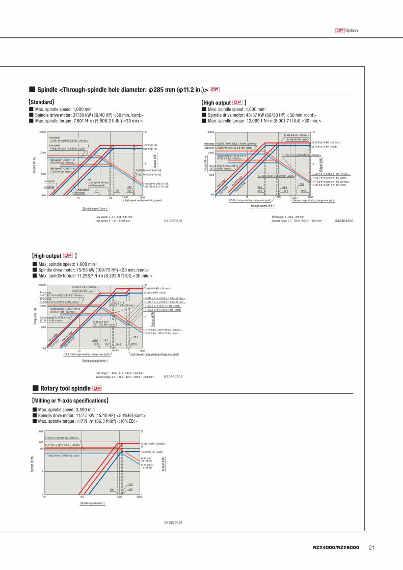
OptionOP
■ Max. spindle speed: 1,000 min-1
■ Spindle drive motor: 37/30 kW (50/40 HP) <30 min./cont>■ Max. spindle torque: 7,601 N・m (5,606.2 ft·lbf) <30 min.>
■ Max. spindle speed: 1,000 min-1
■ Spindle drive motor: 45/37 kW (60/50 HP) <30 min./cont>■ Max. spindle torque: 12,069.1 N・m (8,901.7 ft·lbf) <30 min.>
■ Spindle <Through-spindle hole diameter: φ285 mm (φ11.2 in.)> OP
【Standard】 【High output OP 】
Low speed: 1 – 47 – 544 – 593 min-1
High speed: 3 – 124 – 1,000 min-1
First range: 1 – 38.6 – 350 min-1
Second range: 2.6 – 102.8 – 965.2 – 1,000 min-1
Spindle speed (min-1)
Outp
ut (k
W)
Torq
ue (N・
m)
Low speed T=7601 N・m (5606.2 ft・lbf) <30 min.>
Low speed T=6063 N・m (4471.8 ft・lbf) <cont>
High speed T=2851 N・m (2102.8 ft・lbf) <30 min.>
High speed T=2311 N・m (1704.5 ft・lbf) <cont>
100000 100
10
1
10000
1000
1001 10 100 1000249
(High speed winding switching speed)
Low speed
Low speedHigh speed
High speed
37 kW (50 HP)
30 kW (40 HP)
T=650 N・m (479.4 ft・lbf)
T=527 N・m (388.7 ft・lbf)
T=353 N・m (260.4 ft・lbf)T=287 N・m (211.7 ft・lbf)
94 (Low speed winding switching speed)
47 124 544
593
Spindle speed (min-1)
Outp
ut (k
W)
Torq
ue (N・
m)
100000 100
10
1
10000
1000
1001 10 100 1000232.1
(Second range winding change-over point)
965.235.638.6
102.894.9
350
First range T=12069.1 N・m (8901.7 ft・lbf) <30 min.>
First range T=9160.2 N・m (6756.2 ft・lbf) <cont>
87 (First range winding change-over point)
Second range T=4526.4 N・m (3338.5 ft・lbf) <30 min.>
Second range T=3435.4 N・m (2533.8 ft・lbf) <cont>
45 kW (60 HP) <30 min.>
37 kW (50 HP) <cont>
First
range
First
range
Seco
nd ra
nge
Seco
nd ra
nge
T=1227.8 N・m (905.6 ft・lbf) <30 min.>
T=1009.5 N・m (744.6 ft・lbf) <cont>
43.4 kW (57.9 HP) <30 min.>
35.7 kW (47.6 HP) <cont>
T=445.2 N・m (328.4 ft・lbf) <30 min.>T=366.1 N・m (270.0 ft・lbf) <cont>
T=414.8 N・m (305.9 ft・lbf) <30 min.>T=341.0 N・m (251.5 ft・lbf) <cont>
■ Max. spindle speed: 1,000 min-1
■ Spindle drive motor: 75/55 kW (100/75 HP) <30 min./cont>■ Max. spindle torque: 11,298.7 N・m (8,333.5 ft·lbf) <30 min.>
【High output OP 】
First range: 1 – 43.5 – 116 – 148.4 – 350 min-1
Second range: 2.6 – 116.0 – 323.7 – 395.6 – 1,000 min-1
■ Max. spindle speed: 3,500 min-1
■ Spindle drive motor: 11/7.5 kW (15/10 HP) <50%ED/cont>■ Max. spindle torque: 117 N・m (86.3 ft·lbf) <10%ED>
■ Rotary tool spindle OP
【Milling or Y-axis specifications】
Spindle speed (min-1)
Outp
ut (k
W)
Torq
ue (N・
m)
T=117 N・m (86.3 ft・lbf) <10%ED>
T=84 N・m (62.0 ft・lbf) <50%ED>
T=62.3 N・m (45.9 ft・lbf) <cont>
1 1
20
10
10
100
200
600
1000100 3500
11 kW (15 HP) <50%ED>10
7.5 kW (10 HP) <cont>
T=20.5 N・m(15.1 ft・lbf)
T=30 N・m(22.1 ft・lbf)
900 1250
1150
Q43670A01
Q43465A02
Q43659A01 Q43464A02
Spindle speed (min-1)
Out
put (
kW)
Torq
ue (N・
m)
100000 100
10
1
10000
1000
1001 10
100
1000
First range T=11298.7 N・m (8333.5 ft・lbf) <30 min.>First range T=9874.7 N・m (7283.2 ft・lbf) <cont>
Second range T=4237.4 N・m (3125.3 ft・lbf) <30 min.>
Second range T=3703.4 N・m (2731.5 ft・lbf) <cont>
First
range
First
range Sec
ond r
ange
Secon
d ran
ge
350 (Second range winding change-over point)
43.546.4
121.4 (First range winding change-over point)
123.9
148.4
116.0
T=4827.6 N・m (3560.6 ft・lbf) <30 min.>
T=3540.3 N・m (2611.2 ft・lbf) <cont>
75 kW (100 HP) <30 min.>
55 kW (75 HP) <cont>
T=1810.5 N・m (1335.4 ft・lbf) <30 min.>T=1327.7 N・m (979.3 ft・lbf) <cont>
T=715.2 N・m (527.5 ft・lbf) <30 min.>T=525.2 N・m (387.4 ft・lbf) <cont>
T=2046.3 N・m (1509.3 ft・lbf) <30 min.>
T=1500.6 N・m (1106.8 ft・lbf) <cont>
55 kW (75 HP) <30 min.>
45 kW (60 HP) <cont>
395.6
148.4
22 NZX4000/NZX6000
Spindle speed (min-1)
Outp
ut (k
W)
Torq
ue (N・
m)
100000 100
10
1
10000
1000
1001 10 100 1000
965.235.638.6
102.894.9
First range T=12069.1 N・m (8901.7 ft・lbf) <30 min.>
First range T=9160.2 N・m (6756.2 ft・lbf) <cont>
87 (First range winding change-over point)
Second range T=4526.4 N・m (3338.5 ft・lbf) <30 min.>
Second range T=3435.4 N・m (2533.8 ft・lbf) <cont>
45 kW (60 HP) <30 min.>
37 kW (50 HP) <cont>
First
range
First
range
Seco
nd ra
nge
Seco
nd ra
nge
T=1227.8 N・m (905.6 ft・lbf) <30 min.>
T=1009.5 N・m(744.6 ft・lbf) <cont>
43.4 kW (57.9 HP) <30 min.>
35.7 kW (47.6 HP) <cont>
T=445.2 N・m (328.4 ft・lbf) <30 min.>T=366.1 N・m (270.0 ft・lbf) <cont>
T=414.8 N・m (305.9 ft・lbf) <30 min.>T=341.0 N・m (251.5 ft・lbf) <cont>
350
232.1(Second range winding change-over point)
Spindle speed (min-1)
Outp
ut (k
W)
Torq
ue (N・
m)
100000 100
10
1
10000
1000
1001 10 100 1000
First range T=11298.7 N・m (8333.5 ft・lbf) <30 min.>
First range T=9874.7 N・m (7283.2 ft・lbf) <cont>
Second range T=4237.4 N・m (3125.3 ft・lbf) <30 min.>
Second rangeT=3703.4 N・m (2731.5 ft・lbf) <cont>
First
range
First
range Se
cond
rang
e
Seco
nd ra
nge
43.546.4 116.0
T=4827.6 N・m (3560.6 ft・lbf) <30 min.>
T=3540.3 N・m(2611.2 ft・lbf) <cont>
75 kW (100 HP) <30 min.>
55 kW (75 HP) <cont>
T=1810.5 N・m (1335.4 ft・lbf) <30 min.>
T=1327.7 N・m (979.3 ft・lbf) <cont>
T=715.2 N・m(527.5 ft・lbf) <30 min.>
T=525.2 N・m(387.4 ft・lbf) <cont>
T=2046.3 N・m (1509.3 ft・lbf) <30 min.>
T=1500.6 N・m (1106.8 ft・lbf) <cont>
395.6
350.0123.9
148.4
121.4(First range winding change-over point)
323.6(Second range winding change-over point)
55 kW (75 HP) <30 min.>
45 kW (60 HP) <cont>
Spindle speed-torque/output-rotation speed diagram
■ Max. spindle speed: 1,000 min-1
■ Spindle drive motor: 45/37 kW (60/50HP) <30 min./cont>■ Max. spindle torque: 12,069.1 N・m (8,901.7 ft·lbf) <30 min.>
【Standard】
First range: 1 – 38.6 – 350 min-1
Second range: 2.6 – 102.8 – 965.2 – 1,000 min-1
■ Max. spindle speed: 1,000 min-1
■ Spindle drive motor: 75/55 kW (100/75HP) <30 min./cont>■ Max. spindle torque: 11,298.7 N・m (8,333.5 ft·lbf) <30 min.>
【High output OP 】
First range: 1 – 43.5 – 116 – 148.4 – 350 min-1
Second range: 2.6 – 116.0 – 323.6 – 395.6 – 1,000 min-1
■ Spindle <Through-spindle hole diameter: φ285 mm (φ11.2 in.)>
NZX6000
■ Max. spindle speed: 500 min-1
■ Spindle drive motor: 45/37 kW (60/50HP) <30 min./cont>■ Max. spindle torque: 12,082.2 N・m (8,911.3 ft·lbf) <30 min.>
■ Max. spindle speed: 500 min-1
■ Spindle drive motor: 75/55 kW (100/75HP) <30 min./cont>■ Max. spindle torque: 11,298.7 N・m (8,333.5 ft·lbf) <30 min.>
■ Spindle <Through-spindle hole diameter: φ375 mm (φ14.7 in.)> OP
【Standard】 【High output OP 】
Spindle speed (min-1)
Outp
ut (k
W)
Torq
ue (N・
m)
32.6 kW (43.5 HP) <30 min.>
26.8 kW (35.7 HP) <cont>
100000 100
10
1
10000
1000
1001 10 100 500
38.6
87(Winding change-over speed)
362.035.6
45 kW (60 HP) <30 min.>
37 kW (50 HP) <cont>
T=622.2 N・m (458.9 ft・lbf) <30 min.>T=511.5 N・m (377.3 ft・lbf) <cont>
T=1187.1 N・m (875.6 ft・lbf) <30 min.>
T=976.1 N・m (719.9 ft・lbf) <cont>
T=12082.2 N・m (8911.3 ft・lbf) <30 min.>
T=9170.1 N・m (6763.5 ft・lbf) <cont>
Spindle speed (min-1)
Outp
ut (k
W)
Torq
ue (N・
m)
59.34 kW (79.1 HP) <30 min.>
43.52 kW (58.0 HP) <cont>
100000 100
10
1
10000
1000
10010 100 500
T=1133.3 N・m (835.9 ft・lbf) <30 min.>
T=1810.4 N・m (1335.3 ft・lbf) <30 min.>
T=831.1 N・m (613.0 ft・lbf) <cont>
T=1327.6 N・m (979.2 ft・lbf) <cont>
46.5
121.2 (Winding change-over speed) 395.6
43.5
T=4827.6 N・m (3560.6 ft・lbf) <30 min.>
T=3540.3 N・m (2611.2 ft・lbf) <cont>
148.2
55 kW (75 HP) (cont)
75 kW (100 HP) (30 min.)
1
45 kW (60 HP) <cont>
55 kW (75 HP) <30 min.>
T=11298.7 N・m (8333.5 ft・lbf) <30 min.>
T=9874.7 N・m (7283.2 ft・lbf) <cont>
Q43458A02
Q43464A02
Q43462A02
Q43465A02
Diagrams
23NZX4000/NZX6000
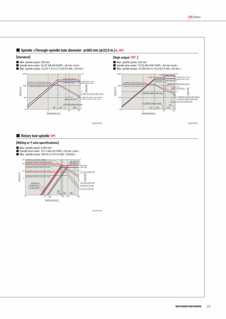
OptionOP
■ Max. spindle speed: 350 min-1
■ Spindle drive motor: 45/37 kW (60/50HP) <30 min./cont>■ Max. spindle torque: 15,231.1 N・m (11,233.9 ft·lbf) <30 min.>
【Standard】■ Max. spindle speed: 350 min-1
■ Spindle drive motor: 75/55 kW (100/75HP) <30 min./cont>■ Max. spindle torque: 14,258.9 N・m (10,516.8 ft·lbf) <30 min.>
【High output OP 】
■ Spindle <Through-spindle hole diameter: φ560 mm (φ22.0 in.)> OP
100000
10000
1000
100
10
11001 10 100
Torq
ue (N・
m)
Spindle speed (min-1)
Outp
ut (k
W)
28.2 30.6 286.8
350
37 kW (50 HP) <30 min.>30 kW (40 HP) <cont>
T=1498.1 N・m (1104.9 ft・lbf) <30 min.>
T=1006.2 N・m (742.1 ft・lbf) <30 min.>T=827.3 N・m (610.2 ft・lbf) <cont>
69.0 (Winding change-over speed)
T=1231.8 N・m(908.5 ft・lbf) <cont>
45 kW (60 HP) (30 min.)
37 kW (50 HP) (cont)
T=11560.0 N・m (8526.2 ft・lbf) <cont>
T=15231.1 N・m (11233.9 ft・lbf) <30 min.>
100000
10000
1000
100
10
11001 10 100
Torq
ue (N・
m)
Spindle speed (min-1)
Outp
ut (k
W)
T=12461.8 N・m (9191.3 ft・lbf) <cont>
75 kW (100 HP) <30 min.>
55 kW (75 HP) <cont>45 kW (60 HP) <cont>
55 kW (75 HP) <30 min.> 67 kW (89.3 HP) <30 min.>49 kW (65.3 HP) <cont>
T=6092.5 N・m (4493.6 ft・lbf) <30 min.>
T=1832.8 N・m (1351.8 ft・lbf) <30 min.>
T=2284.7 N・m (1685.1 ft・lbf) <30 min.>
T=1344.0 N・m (991.3 ft・lbf) <cont>
34.5 36.8 117.6
313.5
350
T=4467.8 N・m (3295.3 ft・lbf) <cont>
T=1675.4 N・m (1235.7 ft・lbf) <cont>96.2 (Winding change-over speed)
T=14258.9 N・m (10516.8 ft・lbf) <30 min.>
■ Max. spindle speed: 6,000 min-1
■ Spindle drive motor: 15/11 kW (20/15HP) <30 min./cont>■ Max. spindle torque: 200 N・m (147.5 ft·lbf) <25%ED>
■ Rotary tool spindle OP
【Milling or Y-axis specifications】
Spindle speed (min-1)
Outp
ut (k
W)
Torq
ue (N・
m)
300
100
200
50
30
20
10
110 100 1000 1620 6000
T=200 N・m (147.5 ft・lbf) <25%ED>
High speed T=88.4 N・m (65.2 ft・lbf) <30 min.>
Low speed 25%ED
120
Low speed 30 min.
Low speed cont
715 3500800
750
15 kW (20 HP)11 kW (15 HP)
High speed 30 min.
High speed cont
T=71.6 N・m (52.8 ft・lbf)
T=23.9 N・m (17.6 ft・lbf)
T=17.5 N・m (12.9 ft・lbf)
T=52.5 N・m (38.7 ft・lbf)
Low speed T=179 N・m (132.0 ft・lbf) <30 min.>
Low speed T=140 N・m (103.3 ft・lbf) <cont>
High speed T=64.8 N・m (47.8 ft・lbf) <cont>
Q43678A01 Q43679A01
Q43471A01
24 NZX4000/NZX6000
L
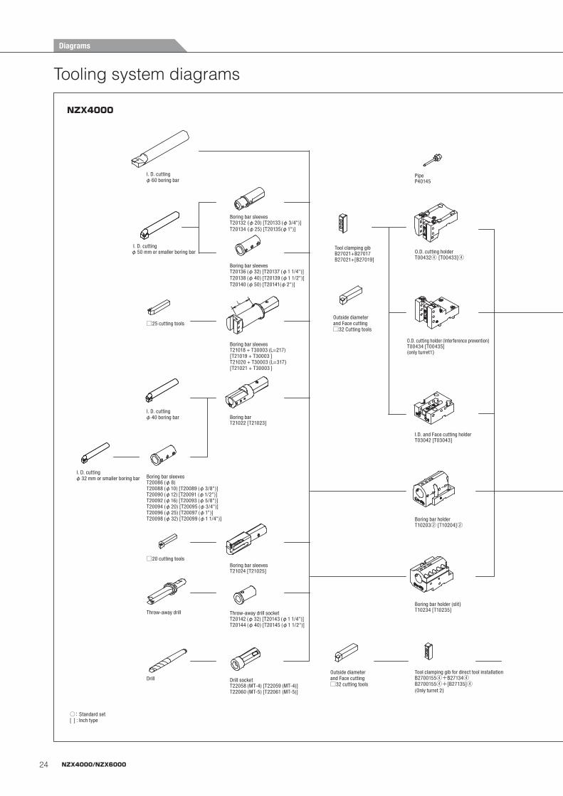
○: Standard set[ ] : Inch type
Boring bar sleeves
I. D. cuttingφ60 boring bar
I. D. cutting
□25 cutting tools
I. D. cuttingφ40 boring bar
□20 cutting tools
Throw-away drill
Drill
I. D. cuttingφ32 mm or smaller boring bar
T21022 [T21023]
T21024 [T21025]
Boring bar sleeves
Boring bar sleeves
Boring bar sleeves
Boring bar
Boring bar sleeves
Throw-away drill socket
Drill socket
T20142 (φ32) [T20143 (φ1 1/4")]T20144 (φ40) [T20145 (φ1 1/2")]
T22058 (MT-4) [T22059 (MT-4)]T22060 (MT-5) [T22061 (MT-5)]
T21018 + T30003 (L=217)[T21019 + T30003 ]T21020 + T30003 (L=317)[T21021 + T30003 ]
T20132 (φ20) [T20133 (φ3/4")]T20134 (φ25) [T20135(φ1")]
T20136 (φ32) [T20137 (φ1 1/4")]T20138 (φ40) [T20139 (φ1 1/2")]T20140 (φ50) [T20141(φ2")]
Boring bar holderT10203② [T10204]②
T00434 [T00435](only turret1)
O.D. cutting holderT00432④ [T00433]④
I.D. and Face cutting holderT03042 [T03043]
B27021+B27017B27021+[B27019]
PipeP40145
Tool clamping gib for direct tool installationB2700155④+B27134④B2700155④+[B27135]④(Only turret 2)
Boring bar holder (slit)T10234 [T10235]
Outside diameter and Face cutting□32 Cutting tools
Outside diameter and Face cutting□32 cutting tools
O.D. cutting holder (Interference prevention)
Tool clamping gib
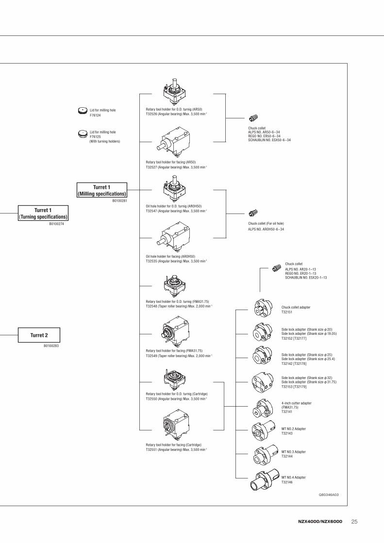
B0100274
B0100283
Turret 1(Turning specifications)
Turret 2
Chuck colletALPS NO. AR50-6−34
SCHAUBLIN NO. ESX50-6−34REGO NO. ER50-6−34
T20086 (φ8)T20088 (φ10) [T20089 (φ3/8")]T20090 (φ12) [T20091 (φ1/2")]T20092 (φ16) [T20093 (φ5/8")]T20094 (φ20) [T20095 (φ3/4")]T20096 (φ25) [T20097 (φ1")]T20098 (φ32) [T20099 (φ1 1/4")]
φ50 mm or smaller boring bar
T32151
T32152 [T32177]
T32142 [T32178]
T32153 [T32179]
T32141
T32143
T32144
T32146
Chuck collet
ALPS NO. AR20-1−13REGO NO. ER20-1−13SCHAUBLIN NO. ESX20-1−13
Chuck collet adapter
Side lock adapter (Shank size φ20)Side lock adapter (Shank size φ19.05)
Side lock adapter (Shank size φ25)Side lock adapter (Shank size φ25.4)
Side lock adapter (Shank size φ32)Side lock adapter (Shank size φ31.75)
4-inch cutter adapter(FMA31.75)
MT NO.2 Adapter
MT NO.3 Adapter
MT NO.4 Adapter
Rotary tool holder for O.D. turnig (AR50)T32526 (Angular bearing) Max. 3,500 min-1
T32527 (Angular bearing) Max. 3,500 min-1
Rotary tool holder for facing (AR50)
Oil hole holder for facing (AROH50)
Chuck collet (For oil hole)
ALPS NO. AROH50-6−34
Oil hole holder for O.D. turnig (AROH50)T32547 (Angular bearing) Max. 3,500 min-1
T32535 (Angular bearing) Max. 3,500 min-1
Rotary tool holder for O.D. turnig (FMA31.75)T32548 (Taper roller bearing) Max. 2,000 min-1
T32549 (Taper roller bearing) Max. 2,000 min-1
Rotary tool holder for facing (FMA31.75)
Rotary tool holder for O.D. turnig (Cartridge)
Rotary tool holder for facing (Cartridge)T32551 (Angular bearing) Max. 3,500 min-1
T32550 (Angular bearing) Max. 3,500 min-1
B0100281
Turret 1(Milling specifications)
Lid for milling hole
Lid for milling hole
F76124
F76125(With turning holders)
Tooling system diagrams
NZX4000
Diagrams
25NZX4000/NZX6000
L
○: Standard set[ ] : Inch type
Boring bar sleeves
I. D. cuttingφ60 boring bar
I. D. cutting
□25 cutting tools
I. D. cuttingφ40 boring bar
□20 cutting tools
Throw-away drill
Drill
I. D. cuttingφ32 mm or smaller boring bar
T21022 [T21023]
T21024 [T21025]
Boring bar sleeves
Boring bar sleeves
Boring bar sleeves
Boring bar
Boring bar sleeves
Throw-away drill socket
Drill socket
T20142 (φ32) [T20143 (φ1 1/4")]T20144 (φ40) [T20145 (φ1 1/2")]
T22058 (MT-4) [T22059 (MT-4)]T22060 (MT-5) [T22061 (MT-5)]
T21018 + T30003 (L=217)[T21019 + T30003 ]T21020 + T30003 (L=317)[T21021 + T30003 ]
T20132 (φ20) [T20133 (φ3/4")]T20134 (φ25) [T20135(φ1")]
T20136 (φ32) [T20137 (φ1 1/4")]T20138 (φ40) [T20139 (φ1 1/2")]T20140 (φ50) [T20141(φ2")]
Boring bar holderT10203② [T10204]②
T00434 [T00435](only turret1)
O.D. cutting holderT00432④ [T00433]④
I.D. and Face cutting holderT03042 [T03043]
B27021+B27017B27021+[B27019]
PipeP40145
Tool clamping gib for direct tool installationB2700155④+B27134④B2700155④+[B27135]④(Only turret 2)
Boring bar holder (slit)T10234 [T10235]
Outside diameter and Face cutting□32 Cutting tools
Outside diameter and Face cutting□32 cutting tools
O.D. cutting holder (Interference prevention)
Tool clamping gib
B0100274
B0100283
Turret 1(Turning specifications)
Turret 2
Chuck colletALPS NO. AR50-6−34
SCHAUBLIN NO. ESX50-6−34REGO NO. ER50-6−34
T20086 (φ8)T20088 (φ10) [T20089 (φ3/8")]T20090 (φ12) [T20091 (φ1/2")]T20092 (φ16) [T20093 (φ5/8")]T20094 (φ20) [T20095 (φ3/4")]T20096 (φ25) [T20097 (φ1")]T20098 (φ32) [T20099 (φ1 1/4")]
φ50 mm or smaller boring bar
T32151
T32152 [T32177]
T32142 [T32178]
T32153 [T32179]
T32141
T32143
T32144
T32146
Chuck collet
ALPS NO. AR20-1−13REGO NO. ER20-1−13SCHAUBLIN NO. ESX20-1−13
Chuck collet adapter
Side lock adapter (Shank size φ20)Side lock adapter (Shank size φ19.05)
Side lock adapter (Shank size φ25)Side lock adapter (Shank size φ25.4)
Side lock adapter (Shank size φ32)Side lock adapter (Shank size φ31.75)
4-inch cutter adapter(FMA31.75)
MT NO.2 Adapter
MT NO.3 Adapter
MT NO.4 Adapter
Rotary tool holder for O.D. turnig (AR50)T32526 (Angular bearing) Max. 3,500 min-1
T32527 (Angular bearing) Max. 3,500 min-1
Rotary tool holder for facing (AR50)
Oil hole holder for facing (AROH50)
Chuck collet (For oil hole)
ALPS NO. AROH50-6−34
Oil hole holder for O.D. turnig (AROH50)T32547 (Angular bearing) Max. 3,500 min-1
T32535 (Angular bearing) Max. 3,500 min-1
Rotary tool holder for O.D. turnig (FMA31.75)T32548 (Taper roller bearing) Max. 2,000 min-1
T32549 (Taper roller bearing) Max. 2,000 min-1
Rotary tool holder for facing (FMA31.75)
Rotary tool holder for O.D. turnig (Cartridge)
Rotary tool holder for facing (Cartridge)T32551 (Angular bearing) Max. 3,500 min-1
T32550 (Angular bearing) Max. 3,500 min-1
B0100281
Turret 1(Milling specifications)
Lid for milling hole
Lid for milling hole
F76124
F76125(With turning holders)
Q80346A03
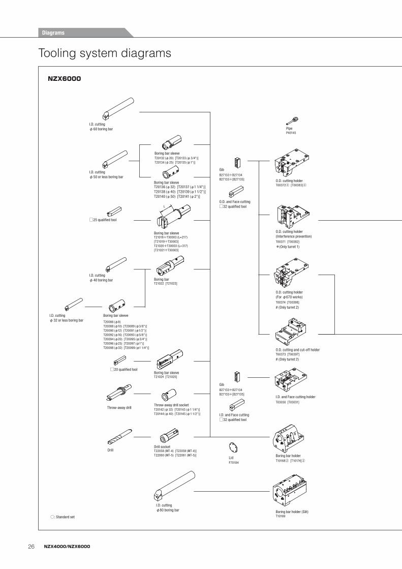
26 NZX4000/NZX6000
L
Turret 1(Turning specifications)
Turret 2
Turret 1(Milling specifications)
I.D. cuttingφ60 boring bar
I.D. cuttingφ50 or less boring bar
□25 qualified tool
I.D. cuttingφ40 boring bar
I.D. cuttingφ32 or less boring bar
Boring bar sleeve
□20 qualified tool
T20086 (φ8)T20088 (φ10) [T20089 (φ3/8")]T20090 (φ12) [T20091 (φ1/2")]T20092 (φ16) [T20093 (φ5/8")]T20094 (φ20) [T20095 (φ3/4")]T20096 (φ25) [T20097 (φ1")]T20098 (φ32) [T20099 (φ1 1/4")]
Throw-away drill
Drill
T20132 (φ20) [T20133 (φ3/4")]T20134 (φ25) [T20135 (φ1")]
Boring bar sleeve
T20136 (φ32) [T20137 (φ1 1/4")]T20138 (φ40) [T20139 (φ1 1/2")]T20140 (φ50) [T20141 (φ2")]
Boring bar sleeve
T21018+T30003 (L=217)[T21019+T30003]T21020+T30003 (L=317)[T21021+T30003]
Boring bar sleeve
T21022 [T21023]Boring bar
T21024 [T21025]Boring bar sleeve
T20142 (φ32) [T20143 (φ1 1/4")]T20144 (φ40) [T20145 (φ1 1/2")]
Throw-away drill socket
T22058 (MT-4) [T22059 (MT-4)]T22060 (MT-5) [T22061 (MT-5)]
Drill socket
I.D. cutting φ80 boring bar
PipeP40145
O.D. and Face cutting □32 qualified tool
GibB27133+B27134B27133+[B27135] O.D. cutting holder
T00372④ [T00383]④
O.D. cutting holder (Interference prevention)
O.D. cutting holder (For φ670 works)T00374 [T00398]
# (Only turret 2)
O.D. cutting and cut-off holderT00373 [T00397]
# (Only turret 2)
GibB27133+B27134B27133+[B27135]
I.D. and Face cutting □32 qualified tool
I.D. and Face cutting holderT03030 [T03031]
LidF70184
Boring bar holderT10168② [T10174]②
Boring bar holder (Slit)T10169
B01254
B01257
B01255
Long boring bar holder (φ130)T11049*Only the long boring bar specification
Long boring bar holder (φ100)T11050*Only the long boring bar specification
LidF83717
Rotary tool holder for O.D. turnig (AR50)T32495(Angular bearing) Max. 3,500 min-1
(Angular bearing) Max. 3,500 min-1
(Angular bearing) Max. 3,500 min-1
(Taper roller bearing) Max. 2,000 min-1
(Angular bearing) Max. 3,500 min-1
(Taper roller bearing) Max. 2,000 min-1
(Angular bearing) Max. 3,500 min-1
(Taper roller bearing) Max. 2,000 min-1
(Angular bearing) Max. 3,500 min-1
(Taper roller bearing) Max. 2,000 min-1
T32496Rotary tool holder for facing (AR50)
T32489
T32490
Rotary tool holder for O.D. turnig (TRX32)
Rotary tool holder for facing (TRX32)T32492
T32493
Rotary tool holder for O.D. turnig (Cartridge)T32491
T32497
Rotary tool holder for facing (Cartridge)T32494
T32498
Chuck colletALPS NO. AR50-6–34REGO NO. ER50-6–34SHAUBLIN NO. ESX50-6–34
Straight collet (For adjusting screw)
ALPS NO. ASS32-6–25
Straight collet ALPS NO. AS32-6–25
Chuck colletALPS NO.AR20-1–13REGO NO.ER20-1–13SHAUBLIN NO.ESX20-1–13
T32151
Chuck collet adapter
T32152 [T32177]
Side lock adapter(Shank size φ20, φ19.05)
T32142 [T32178]
Side lock adapter(Shank size φ25, φ25.4)
T32153 [T32179]
Side lock adapter(Shank size φ32, φ31.75)
T32141
4-inch cutter adapter(FMA31.75)
T32143MT NO.2 Adapter
T32144MT NO.3 Adapter
T32146MT NO.4 Adapter
○: Standard set
T00371 [T00382]
*(Only turret 1)
Tooling system diagrams
NZX6000
Diagrams

27NZX4000/NZX6000
L
Turret 1(Turning specifications)
Turret 2
Turret 1(Milling specifications)
I.D. cuttingφ60 boring bar
I.D. cuttingφ50 or less boring bar
□25 qualified tool
I.D. cuttingφ40 boring bar
I.D. cuttingφ32 or less boring bar
Boring bar sleeve
□20 qualified tool
T20086 (φ8)T20088 (φ10) [T20089 (φ3/8")]T20090 (φ12) [T20091 (φ1/2")]T20092 (φ16) [T20093 (φ5/8")]T20094 (φ20) [T20095 (φ3/4")]T20096 (φ25) [T20097 (φ1")]T20098 (φ32) [T20099 (φ1 1/4")]
Throw-away drill
Drill
T20132 (φ20) [T20133 (φ3/4")]T20134 (φ25) [T20135 (φ1")]
Boring bar sleeve
T20136 (φ32) [T20137 (φ1 1/4")]T20138 (φ40) [T20139 (φ1 1/2")]T20140 (φ50) [T20141 (φ2")]
Boring bar sleeve
T21018+T30003 (L=217)[T21019+T30003]T21020+T30003 (L=317)[T21021+T30003]
Boring bar sleeve
T21022 [T21023]Boring bar
T21024 [T21025]Boring bar sleeve
T20142 (φ32) [T20143 (φ1 1/4")]T20144 (φ40) [T20145 (φ1 1/2")]
Throw-away drill socket
T22058 (MT-4) [T22059 (MT-4)]T22060 (MT-5) [T22061 (MT-5)]
Drill socket
I.D. cutting φ80 boring bar
PipeP40145
O.D. and Face cutting □32 qualified tool
GibB27133+B27134B27133+[B27135] O.D. cutting holder
T00372④ [T00383]④
O.D. cutting holder (Interference prevention)
O.D. cutting holder (For φ670 works)T00374 [T00398]
# (Only turret 2)
O.D. cutting and cut-off holderT00373 [T00397]
# (Only turret 2)
GibB27133+B27134B27133+[B27135]
I.D. and Face cutting □32 qualified tool
I.D. and Face cutting holderT03030 [T03031]
LidF70184
Boring bar holderT10168② [T10174]②
Boring bar holder (Slit)T10169
B01254
B01257
B01255
Long boring bar holder (φ130)T11049*Only the long boring bar specification
Long boring bar holder (φ100)T11050*Only the long boring bar specification
LidF83717
Rotary tool holder for O.D. turnig (AR50)T32495(Angular bearing) Max. 3,500 min-1
(Angular bearing) Max. 3,500 min-1
(Angular bearing) Max. 3,500 min-1
(Taper roller bearing) Max. 2,000 min-1
(Angular bearing) Max. 3,500 min-1
(Taper roller bearing) Max. 2,000 min-1
(Angular bearing) Max. 3,500 min-1
(Taper roller bearing) Max. 2,000 min-1
(Angular bearing) Max. 3,500 min-1
(Taper roller bearing) Max. 2,000 min-1
T32496Rotary tool holder for facing (AR50)
T32489
T32490
Rotary tool holder for O.D. turnig (TRX32)
Rotary tool holder for facing (TRX32)T32492
T32493
Rotary tool holder for O.D. turnig (Cartridge)T32491
T32497
Rotary tool holder for facing (Cartridge)T32494
T32498
Chuck colletALPS NO. AR50-6–34REGO NO. ER50-6–34SHAUBLIN NO. ESX50-6–34
Straight collet (For adjusting screw)
ALPS NO. ASS32-6–25
Straight collet ALPS NO. AS32-6–25
Chuck colletALPS NO.AR20-1–13REGO NO.ER20-1–13SHAUBLIN NO.ESX20-1–13
T32151
Chuck collet adapter
T32152 [T32177]
Side lock adapter(Shank size φ20, φ19.05)
T32142 [T32178]
Side lock adapter(Shank size φ25, φ25.4)
T32153 [T32179]
Side lock adapter(Shank size φ32, φ31.75)
T32141
4-inch cutter adapter(FMA31.75)
T32143MT NO.2 Adapter
T32144MT NO.3 Adapter
T32146MT NO.4 Adapter
○: Standard set
T00371 [T00382]
*(Only turret 1)
Q80332A05
28 NZX4000/NZX6000
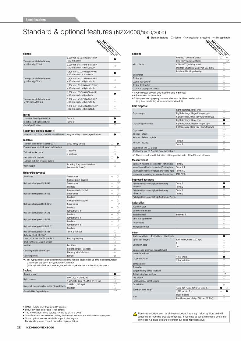
Standard & optional features (NZX4000/1000/2000)● : Standard features ○ : Option ☆ : Consultation is required -: Not applicable
Spindle
Through-spindle hole diameter: φ145 mm (φ5.7 in.)
2,000 min-1: 37/30 kW (50/40 HP) <30 min./cont>
●
2,000 min-1: 45/37 kW (60/50 HP) <30 min./cont> <High output>
○
Through-spindle hole diameter: φ185 mm (φ7.2 in.)
1,500 min-1: 37/30 kW (50/40 HP) <30 min./cont> <Standard>
●
1,500 min-1: 45/37 kW (60/50 HP) <30 min./cont> <High output>
○
1,500 min-1: 75/55 kW (103/75 HP) <30 min./cont> <High output>
○
Through-spindle hole diameter: φ285 mm (φ11.2 in.)
1,000 min-1: 37/30 kW (50/40 HP) <30 min./cont> <Standard>
●
1,000 min-1: 45/37 kW (60/50 HP) <30 min./cont> <High output>
○
1,000 min-1: 75/55 kW (100/75 HP) <30 min./cont> <High output>
○
Turret12-station, bolt-tightened turret Turret 1 ●8-station, bolt-tightened turret Turret 2 ●Capto Specifications ○
Rotary tool spindle (turret 1)3,500 min-1: 11/7.5 kW (15/10 HP) <50%ED/cont> Only for milling or Y-axis specifications ●
TailstockTailstock spindle built-in center (MT5) φ150 mm (φ5.9 in.) ○ ●Programmable tailstock (servo motor driven) ○
Tailstock stroke check1 position ○4 positions ○
Foot switch for tailstock ○ ●Tailstock high/low pressure system ○
Work stopperIncluding Programmable tailstock (servo motor driven).
○
Fixture/Steady restSteady rest Servo-driven - ○
Hydraulic steady rest SLU-X4Z
Carriage direct-coupled - ○Servo-driven - ○*
Interface - ○
Hydraulic steady rest SLU-X5Z
Carriage direct-coupled - ○Servo-driven - ○*
Interface - ○
Hydraulic steady rest SLU-X5.1Z
Carriage direct-coupled - ○Servo-driven - ○*
Interface - ○
Hydraulic steady rest SLU-X4ZWithout turret 2 - ○*
Interface - ○
Hydraulic steady rest SLU-X5ZWithout turret 2 - ○*
Interface - ○
Hydraulic steady rest SLU-X5.1ZWithout turret 2 - ○*
Interface - ○Hydraulic steady rest SLU-X3Z Turret 2 interface ○Hydraulic chuck interface*1 ○Index chuck interface for spindle 1 Electric parts only ○Chuck high/low pressure system ○Air chuck Front/rear ☆
Centering unit for oil-well pipeCentering chuck (Tailstock) ☆Clamping with both turret ☆
Centering chuck Spindle ☆
*1 The hydraulic chuck interface is not included in the standard specification. So if the chuck is mounted at a customer's site, select the hydraulic chuck interface. (If the hydraulic chuck set is selected, the hydraulic chuck interface is automatically included.)
CoolantCoolant system ●
High pressure800/1,100 W (50/60 Hz) ○1 MPa (145.0 psi) / 1.5 MPa (217.5 psi) ○
Super-high pressure coolant system (Separate type)7.0 MPa (1,015.0 psi) ○*
Interface ○Coolant chiller (Separate type) ○*
Coolant
Mist collector
HVS-220*1 (including stand) ○* -HVS-300*1 (including stand) - ○*
AFS-1600*2 (including stand) ○*
Interface <duct only, φ200 mm (φ7.9 in.)> ○Interface (Electric parts only) ○
Oil skimmer ○Coolant gun ○Coolant flow switch*3 ○Coolant float switch ○Coolant in upper part of chuck ○
*1 For oil based coolant only (Not available in Europe)*2 For water-soluble coolant *3 It may not work properly in cases where coolant flow rate is too low.
(e.g. hole machining with a small-diameter drill)
Chip disposal
Chip conveyor
Right discharge, Hinge type ○Right discharge, Magnet scraper type ○Right discharge, Hinge type+Drum filter type ○
Chip conveyor interface
Right discharge, Hinge type ●Right discharge, Magnet scraper type ●Right discharge, Hinge type+Drum filter type ○
Chip bucket ○*
Air blow Chuck ○Air blow Tailstock spindle ○
Air blow Tool tipTurret 1 ○Turret 2 ○
Double slide seal (X, Z-axis) ○Double slide seal (X, Z-axis)+Force-lubrication*1 ○
*1 There is no forced lubrication at the positive side of the X1- and X2-axis.
MeasurementManual in-machine tool presetter (Removable) Turret 2 ○Manual in-machine tool presetter (Pivoting type) Turret 1, 2 ○Automatic in-machine tool presetter (Pivoting type) Turret 1, 2 ○In-machine measuring system wireless sensor MARPOSS ○
Improved accuracyFull closed loop control (Scale feedback) <X-axis>
Turret 1 ●Turret 2 ●
Full closed loop control (Scale feedback) <Z-axis>
Turret 1 ○Turret 2 ○
Full closed loop control (Scale feedback) <Y-axis> ○
AutomationAutomatic door ○
Ethernet/IP interface ○
Robot interface Ethernet/IP ○
Earth leakage breaker ○
Total counter ○
Workpiece counter ○
Other・Built-in worklight ・Tool holders ・Hand tools ●Signal light 3 layers Red, Yellow, Green (LED type) ○
External M-code5 ○10 ○
Manual pulse generator (separate type) ○Power ON indicator ○
Chuck foot switch1 foot switch ●2 foot switches ○
Normal anchor ○Dry anchor ○Danger sensing device Interface ○Refrigerating type air dryer ○*
Tool cabinet ○*
Long boring bar specifications -Capto holder ☆
Operation panel height1,570 mm–1,870 mm (61.8–73.6 in.) ● ○1,570 mm (61.8 in.) - ●
StepInside machine ○Outside machine <height 300 mm (11.8 in.)> ○
* DMQP (DMG MORI Qualified Products)● DMQP: Please see Page 11 for details.● The information in this catalog is valid as of June 2019.● Specifications, accessories, safety device and function are available upon request.● Some options are not available in particular regions.
For details, please consult our sales representative.
Flammable coolant such as oil-based coolant has a high risk of ignition, and will cause fire or machine breakage if ignited. If you have to use a flammable coolant for any reason, please be sure to consult our sales representative.
NZX4000/1000
NZX4000/2000
NZX4000/1000
NZX4000/2000
Specifications
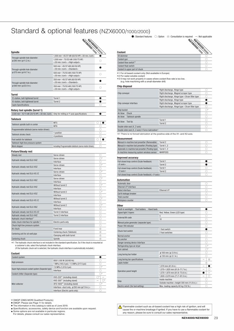
29NZX4000/NZX6000
Standard & optional features (NZX6000/1000/2000)● : Standard features ○ : Option ☆ : Consultation is required -: Not applicable
Spindle
Through-spindle hole diameter: φ285 mm (φ11.2 in.)
1,000 min-1: 45/37 kW (60/50 HP) <30 min./cont> ●1,000 min-1: 75/55 kW (100/75 HP) <30 min./cont> <High output>
○
Through-spindle hole diameter: φ375 mm (φ14.7 in.)
500 min-1: 45/37 kW (60/50 HP) <30 min./cont> <Standard>
●
500 min-1: 75/55 kW (100/75 HP) <30 min./cont> <High output>
○
Through-spindle hole diameter: φ560 mm (φ22.0 in.)
350 min-1: 45/37 kW (60/50 HP) <30 min./cont> <Standard>
●
350 min-1: 75/55 kW (100/75 HP) <30 min./cont> <High output>
○
Turret12-station, bolt-tightened turret Turret 1 ●10-station, bolt-tightened turret Turret 2 ●Capto Specifications ○
Rotary tool spindle (turret 1)3,500 min-1: 15/11 kW (20/15 HP) <30 min./cont> Only for milling or Y-axis specifications ●
Tailstock
Tailstock spindle built-in centerMT5 ○ ●MT6 ○
Programmable tailstock (servo motor driven) ○
Tailstock stroke check1 position ○4 positions ○
Foot switch for tailstock ○ ●Tailstock high/low pressure system ○Work stopper Including Programmable tailstock (servo motor driven). ○
Fixture/Steady restSteady rest Servo-driven ○
Hydraulic steady rest SLU-X4ZServo-driven ○*
Interface ○
Hydraulic steady rest SLU-X5ZServo-driven ○*
Interface ○
Hydraulic steady rest SLU-X5.1ZServo-driven ○*
Interface ○
Hydraulic steady rest SLU-X6ZServo-driven ○*
Interface ○
Hydraulic steady rest SLU-X4ZWithout turret 2 ○*
Interface ○
Hydraulic steady rest SLU-X5ZWithout turret 2 ○*
Interface ○
Hydraulic steady rest SLU-X5.1ZWithout turret 2 ○*
Interface ○
Hydraulic steady rest SLU-X6ZWithout turret 2 ○*
Interface ○Hydraulic steady rest SLU-X3.2Z Turret 2 interface ○Hydraulic steady rest SLU-X4Z Turret 2 interface ○Hydraulic chuck interface*1 ○Index chuck interface for spindle 1 Electric parts only ○Chuck high/low pressure system ○Air chuck Front/rear ☆
Centering unit for oil-well pipeCentering chuck (Tailstock) ☆Clamping with both turret ☆
Centering chuck Spindle ☆
*1 The hydraulic chuck interface is not included in the standard specification. So if the chuck is mounted at a customer's site, select the hydraulic chuck interface. (If the hydraulic chuck set is selected, the hydraulic chuck interface is automatically included.)
CoolantCoolant system ●
High pressure800/1,100 W (50/60 Hz) ○1 MPa (145.0 psi) / 1.5 MPa (217.5 psi) ○
Super-high pressure coolant system (Separate type)7.0 MPa (1,015.0 psi) ○*
Interface ○Coolant chiller (Separate type) ○*
Mist collector
HVS-220*1 (including stand) ○* -HVS-300*1 (including stand) - ○*
AFS-1600*2 (including stand) ○*
Interface <duct only, φ200 mm (φ7.9 in.)> ○Interface (Electric parts only) ○
CoolantOil skimmer ○Coolant gun ○Coolant flow switch*3 ○Coolant float switch ○Coolant in upper part of chuck ○
*1 For oil based coolant only (Not available in Europe)*2 For water-soluble coolant *3 It may not work properly in cases where coolant flow rate is too low.
(e.g. hole machining with a small-diameter drill)
Chip disposal
Chip conveyor
Right discharge, Hinge type ○Right discharge, Magnet scraper type ○Right discharge, Hinge type+Drum filter type ○
Chip conveyor interface
Right discharge, Hinge type ●Right discharge, Magnet scraper type ●Right discharge, Hinge type+Drum filter type ○
Chip bucket ○*
Air blow Chuck ○Air blow Tailstock spindle ○
Air blow Tool tipTurret 1 ○Turret 2 ○
Double slide seal (X, Z-axis) ○Double slide seal (X, Z-axis)+Force-lubrication*1 ○
*1 There is no forced lubrication at the positive side of the X1- and X2-axis.
MeasurementManual in-machine tool presetter (Removable) Turret 2 ○Manual in-machine tool presetter (Pivoting type) Turret 1, 2 ○Automatic in-machine tool presetter (Pivoting type) Turret 1, 2 ○In-machine measuring system wireless sensor MARPOSS ○
Improved accuracyFull closed loop control (Scale feedback) <X-axis>
Turret 1 ●Turret 2 ●
Full closed loop control (Scale feedback) <Z-axis>
Turret 1 ○Turret 2 ○
Full closed loop control (Scale feedback) <Y-axis> ○
AutomationAutomatic door ○Ethernet I/P interface ○Robot interface Ethernet I/P ○Earth leakage breaker ○Total counter ○Workpiece counter ○
Other・Built-in worklight ・Tool holders ・Hand tools ●Signal light 3 layers Red, Yellow, Green (LED type) ○
External M-code5 ○10 ○
Manual pulse generator (separate type) ○Power ON indicator ○
Chuck foot switch1 foot switch ●2 foot switches ○
Normal anchor ○Dry anchor ○Danger sensing device Interface ○Refrigerating type air dryer ○*
Tool cabinet ○*
Long boring bar holderφ100 mm (φ3.9 in.) ○φ130 mm (φ5.1 in.) ○
Long boring bar specifications - ☆Capto holder ☆
Operation panel height
1,570 mm (61.8 in.) - ●1,570–1,820 mm (61.8–71.7 in.) - ○1,570–1,870 mm (61.8–73.6 in.) ● -1,820–2,070 mm (71.7–81.5 in.) - ○
StepInside machine ○Outside machine <height 300 mm (11.8 in.)> ○
Electric winch (for tool setting) Max. loading capacity 60 kg (132 lb.) ○
NZX6000/1000
NZX6000/2000
NZX6000/1000
NZX6000/2000
* DMQP (DMG MORI Qualified Products)● DMQP: Please see Page 11 for details.● The information in this catalog is valid as of June 2019.● Specifications, accessories, safety device and function are available upon request.● Some options are not available in particular regions.
For details, please consult our sales representative.
Flammable coolant such as oil-based coolant has a high risk of ignition, and will cause fire or machine breakage if ignited. If you have to use a flammable coolant for any reason, please be sure to consult our sales representative.
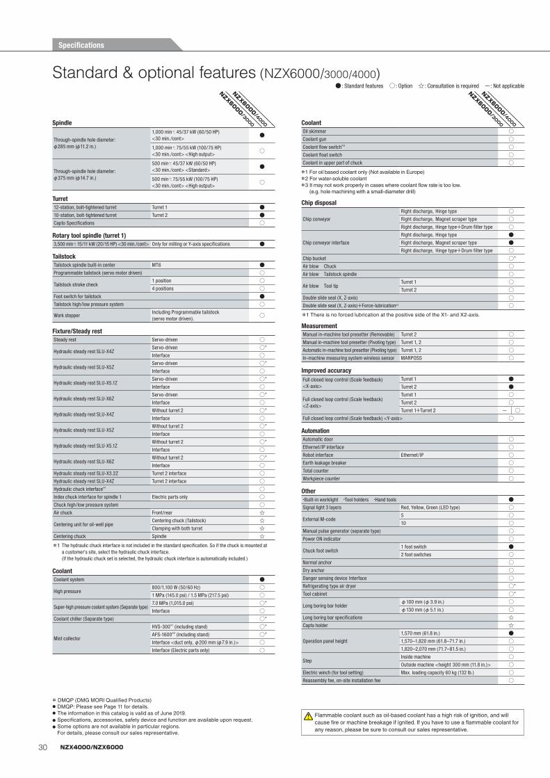
30 NZX4000/NZX6000
Standard & optional features (NZX6000/3000/4000)
Spindle
Through-spindle hole diameter: φ285 mm (φ11.2 in.)
1,000 min-1: 45/37 kW (60/50 HP) <30 min./cont>
●
1,000 min-1: 75/55 kW (100/75 HP) <30 min./cont> <High output>
○
Through-spindle hole diameter: φ375 mm (φ14.7 in.)
500 min-1: 45/37 kW (60/50 HP) <30 min./cont> <Standard>
●
500 min-1: 75/55 kW (100/75 HP) <30 min./cont> <High output>
○
Turret12-station, bolt-tightened turret Turret 1 ●10-station, bolt-tightened turret Turret 2 ●Capto Specifications ○
Rotary tool spindle (turret 1)3,500 min-1: 15/11 kW (20/15 HP) <30 min./cont> Only for milling or Y-axis specifications ●
TailstockTailstock spindle built-in center MT6 ●Programmable tailstock (servo motor driven) ○
Tailstock stroke check1 position ○4 positions ○
Foot switch for tailstock ●Tailstock high/low pressure system ○
Work stopperIncluding Programmable tailstock(servo motor driven).
○
Fixture/Steady restSteady rest Servo-driven ○
Hydraulic steady rest SLU-X4ZServo-driven ○*
Interface ○
Hydraulic steady rest SLU-X5ZServo-driven ○*
Interface ○
Hydraulic steady rest SLU-X5.1ZServo-driven ○*
Interface ○
Hydraulic steady rest SLU-X6ZServo-driven ○*
Interface ○
Hydraulic steady rest SLU-X4ZWithout turret 2 ○*
Interface ○
Hydraulic steady rest SLU-X5ZWithout turret 2 ○*
Interface ○
Hydraulic steady rest SLU-X5.1ZWithout turret 2 ○*
Interface ○
Hydraulic steady rest SLU-X6ZWithout turret 2 ○*
Interface ○Hydraulic steady rest SLU-X3.2Z Turret 2 interface ○Hydraulic steady rest SLU-X4Z Turret 2 interface ○Hydraulic chuck interface*1 ○Index chuck interface for spindle 1 Electric parts only ○Chuck high/low pressure system ○Air chuck Front/rear ☆
Centering unit for oil-well pipeCentering chuck (Tailstock) ☆Clamping with both turret ☆
Centering chuck Spindle ☆
*1 The hydraulic chuck interface is not included in the standard specification. So if the chuck is mounted at a customer's site, select the hydraulic chuck interface. (If the hydraulic chuck set is selected, the hydraulic chuck interface is automatically included.)
CoolantCoolant system ●
High pressure800/1,100 W (50/60 Hz) ○1 MPa (145.0 psi) / 1.5 MPa (217.5 psi) ○
Super-high pressure coolant system (Separate type)7.0 MPa (1,015.0 psi) ○*
Interface ○Coolant chiller (Separate type) ○*
Mist collector
HVS-300*1 (including stand) ○*
AFS-1600*2 (including stand) ○*
Interface <duct only, φ200 mm (φ7.9 in.)> ○Interface (Electric parts only) ○
CoolantOil skimmer ○Coolant gun ○Coolant flow switch*3 ○Coolant float switch ○Coolant in upper part of chuck ○
*1 For oil based coolant only (Not available in Europe)*2 For water-soluble coolant *3 It may not work properly in cases where coolant flow rate is too low.
(e.g. hole machining with a small-diameter drill)
Chip disposal
Chip conveyor
Right discharge, Hinge type ○Right discharge, Magnet scraper type ○Right discharge, Hinge type+Drum filter type ○
Chip conveyor interface
Right discharge, Hinge type ●Right discharge, Magnet scraper type ●Right discharge, Hinge type+Drum filter type ○
Chip bucket ○*
Air blow Chuck ○Air blow Tailstock spindle ○
Air blow Tool tipTurret 1 ○Turret 2 ○
Double slide seal (X, Z-axis) ○Double slide seal (X, Z-axis)+Force-lubrication*1 ○
*1 There is no forced lubrication at the positive side of the X1- and X2-axis.
MeasurementManual in-machine tool presetter (Removable) Turret 2 ○Manual in-machine tool presetter (Pivoting type) Turret 1, 2 ○Automatic in-machine tool presetter (Pivoting type) Turret 1, 2 ○In-machine measuring system wireless sensor MARPOSS ○
Improved accuracyFull closed loop control (Scale feedback)<X-axis>
Turret 1 ●Turret 2 ●
Full closed loop control (Scale feedback)<Z-axis>
Turret 1 ○Turret 2 ○Turret 1+Turret 2 - ○
Full closed loop control (Scale feedback) <Y-axis> ○
AutomationAutomatic door ○Ethernet/IP interface ○Robot interface Ethernet/IP ○Earth leakage breaker ○Total counter ○Workpiece counter ○
Other・Built-in worklight ・Tool holders ・Hand tools ●Signal light 3 layers Red, Yellow, Green (LED type) ○
External M-code5 ○10 ○
Manual pulse generator (separate type) ○Power ON indicator ○
Chuck foot switch1 foot switch ●2 foot switches ○
Normal anchor ○Dry anchor ○Danger sensing device Interface ○Refrigerating type air dryer ○*
Tool cabinet ○*
Long boring bar holderφ100 mm (φ3.9 in.) ○φ130 mm (φ5.1 in.) ○
Long boring bar specifications ☆Capto holder ☆
Operation panel height
1,570 mm (61.8 in.) ●1,570–1,820 mm (61.8–71.7 in.) ○1,820–2,070 mm (71.7–81.5 in.) ○
StepInside machine ○Outside machine <height 300 mm (11.8 in.)> ○
Electric winch (for tool setting) Max. loading capacity 60 kg (132 lb.) ○Reassembly fee, on-site installation fee ○
NZX6000/3000
NZX6000/4000
NZX6000/3000
NZX6000/4000
● : Standard features ○ : Option ☆ : Consultation is required -: Not applicable
* DMQP (DMG MORI Qualified Products)● DMQP: Please see Page 11 for details.● The information in this catalog is valid as of June 2019.● Specifications, accessories, safety device and function are available upon request.● Some options are not available in particular regions.
For details, please consult our sales representative.
Flammable coolant such as oil-based coolant has a high risk of ignition, and will cause fire or machine breakage if ignited. If you have to use a flammable coolant for any reason, please be sure to consult our sales representative.
Specifications
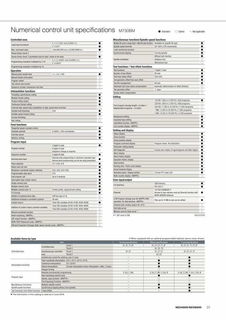
31NZX4000/NZX6000
● : Standard ○ : Option -: Not applicable Numerical control unit specifications M730BM
Controlled axes
Least input incrementX, Y, Z: 0.001 mm (0.0001 in.) ●C: 0.001° ●
Max. command value ±99,999.999 mm (±9,999.9999 in.) ●Stored stroke check 2 ○Stored stroke check 3 (prohibited area to enter: inside of set area) ●
Programming resolution multiplied by 1/10X, Y, Z: 0.0001 mm (0.00001 in.) ○C: 0.0001° ○
Programming resolution multiplied by 10 ○
OperationManual pulse handle feed ×1, ×10, ×100 ●Manual handle interruption ○Program restart ○Tool retract and recover ○Sequence number comparison and stop ○
Interpolation functionsThreading, synchronous cutting ●Multiple thread cutting ●Thread cutting retract ●Continuous thread cutting ●External high-speed skip (Installation of high-speed skip terminal) ○Variable lead threading G34 ●Variable speed thread cutting ●Circular threading ○Hob cutting ○
Feed functionsTangential speed constant control ●Feedrate override 0-200% <10% increments> ●Override cancel ●Balance cutting ●
Program input
Program number4 digits O code ●8 digits O code Sequence change is required
○
Sequence number 5 digits N code ●
Decimal point inputDecimal point programming or electronic calculator type decimal point programming can be set using parameters
●
Plane selection G17, G18, G19 ●Rotary axis roll-over ●Workpiece coordinate system selection G52, G53, G54-G59 ●Programmable data input G10 ●Sub-program call Up to 8 nestings ●Interruption type custom macro ●Single canned cycle ●Multiple canned cycle ●Multiple canned cycle Ⅱ Pocket profile, zigzag thread cutting ●F15 format ●Addition of optional block skip Soft key type (2-9) ○Additional workpiece coordinate systems 48 sets ○Custom macro Total 200 variables (#100-#199, #500-#599) ●
Addition of custom macro common variablesTotal 300 variables (#100-#199, #500-#699) ○Total 600 variables (#100-#199, #500-#999) ○
Manual coordinate function ○Relief machining <MAPPS> ○DXF import function <MAPPS> ○MORI-POST Advanced mode <MAPPS> ○Efficient Production Package (High-speed canned cycle) <MAPPS> ○
Miscellaneous functions/Spindle speed functionsMultiple M cords in single block <Multi M code function> Available for specific M code ●Spindle speed override 50-150% (10% increments) ●Load monitoring function ●Synchronous tapping Turning spindle ●
Spindle orientation
Without lock function ●Software lock ○Mechanical lock ○
Tool functions / Tool offset functionsTool functions 4 digits T code ●Number of tool offsets 80 sets ●Tool nose radius offset G40-G42 ●Tool geometry offset/Tool wear offset ●Tool life management 80 sets ●Automatic tool nose radius compensation automatic determination of offset direction ○Tool geometry offset Ⅰ-type ○Groove width compensation ○
Editing
Part program storage length <in total>/Registerable programs <in total>
125 KB <320 m (1,050 ft)>/200 programs ●230 KB <600 m (1,970 ft)>/400 programs ○500 KB <1,280 m (4,200 ft)>/1,000 programs ○1 MB <2,560 m (8,400 ft)>/1,000 programs ○2 MB <5,120 m (16,800 ft)>/1,000 programs ○
Background editing ●Expanded tape editing ●Undo/Redo function <MAPPS> ●Line number display <MAPPS> ●
Setting and displayStatus display ●Clock function ●Actual position display ●Program comment display Program name: 48 characters ●Parameter setting display ●Self-diagnosis Includes alarm display, I/O signal diagnosis and ladder diagram ●Alarm display ●Alarm history display ●Operation history display ●Help function ●Running time / Parts count display ●Actual feedrate display ●Operation panel : Display section 19-inch TFT color LCD ●Multi-counter display <MAPPS> ○
Data input/output
I/O interfaceUSB memory ●RS-232-C ●
Ethernet10/100/1000BASE-T Access to user memory area by Ethernet function with MORI-SERVER Software
●
6 GB Program storage area (for MAPPS-DNC operation, for data backup) <MAPPS>
Files up to 10 MB in size can be edited ●
External work number search (#1-#15) ○Fast data server ○Memory card for Data server *1 ○
*1 SD card 2 GB
Available items by type *When equipped with an optional programmable tailstock (servo motor driven)
Item Turning specifications Milling specifications Y-axis specifications
Controlled axes
Controlled axesTurret 1 X1, Z1, T1, B* X1, Z1, C1, T1, B* X1, Z1, C1, T1, Y1, B*
Turret 2 X2, Z2, T2
Simultaneously controlled axes
Turret 1 X1, Z1 X1, Z1, C1 X1, Z1, C1, Y1Turret 2 X2, Z2
Inclined axis control for arbitrary axis (Y-axis) - - ●
Interpolation functions
Polar coordinate interpolation G12.1, G13.1 (G112, G113) - ● ●Cylindrical interpolation G7.1 (G107) - ● ●Helical interpolation Circular interpolation+linear interpolation <Max. 2 axes> - ● ●Polygon turning - ○ ○
Program input
Absolute (incremental) programming X (U), Z (W) X (U), Z (W), C (H), B X (U), Z (W), Y (V), C (H), BHole machining canned cycle - ● ●Islands, open pockets <MAPPS> - ○ ○Text Engraving Function <MAPPS> - ○ ○
Miscellaneous functions/Spindle speed functions
Multiple-spindle control - ● ●Synchronous tapping (Rotary tool spindle) - ● ●
Tool functions/Tool offset functions Y-axis offset - - ●● The information in this catalog is valid as of June 2019.
I95031A06
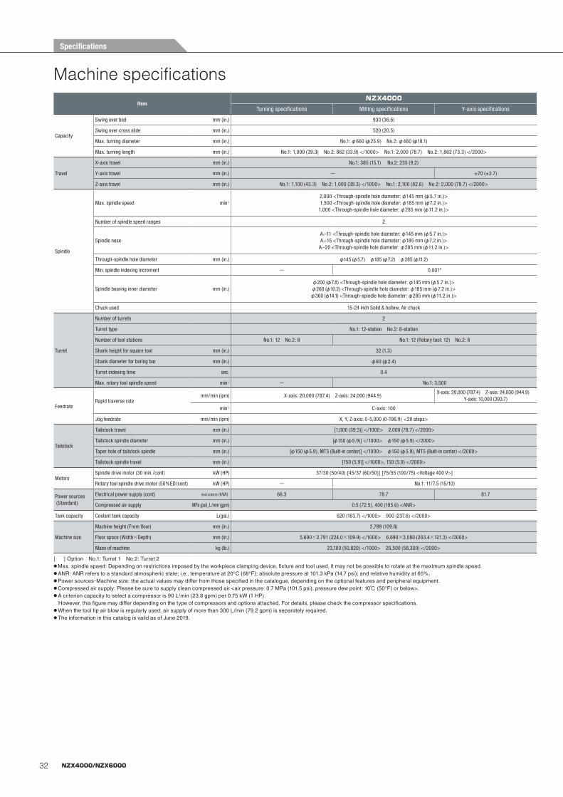
32 NZX4000/NZX6000
Machine specificationsItem
NZX4000
Turning specifications Milling specifications Y-axis specifications
Capacity
Swing over bed mm (in.) 930 (36.6)
Swing over cross slide mm (in.) 520 (20.5)
Max. turning diameter mm (in.) No.1: φ660 (φ25.9) No.2: φ460 (φ18.1)
Max. turning length mm (in.) No.1: 1,000 (39.3) No.2: 862 (33.9) </1000> No.1: 2,000 (78.7) No.2: 1,862 (73.3) </2000>
Travel
X-axis travel mm (in.) No.1: 385 (15.1) No.2: 235 (9.2)
Y-axis travel mm (in.) - ±70 (±2.7)
Z-axis travel mm (in.) No.1: 1,100 (43.3) No.2: 1,000 (39.3) </1000> No.1: 2,100 (82.6) No.2: 2,000 (78.7) </2000>
Spindle
Max. spindle speed min-1
2,000 <Through-spindle hole diameter: φ145 mm (φ5.7 in.)>1,500 <Through-spindle hole diameter: φ185 mm (φ7.2 in.)>
1,000 <Through-spindle hole diameter: φ285 mm (φ11.2 in.)>
Number of spindle speed ranges 2
Spindle noseA2-11 <Through-spindle hole diameter: φ145 mm (φ5.7 in.)>A2-15 <Through-spindle hole diameter: φ185 mm (φ7.2 in.)>
A1-20 <Through-spindle hole diameter: φ285 mm (φ11.2 in.)>
Through-spindle hole diameter mm (in.) φ145 (φ5.7) φ185 (φ7.2) φ285 (φ11.2)
Min. spindle indexing increment - 0.001°
Spindle bearing inner diameter mm (in.)φ200 (φ7.8) <Through-spindle hole diameter: φ145 mm (φ5.7 in.)>φ260 (φ10.2) <Through-spindle hole diameter: φ185 mm (φ7.2 in.)>φ360 (φ14.1) <Through-spindle hole diameter: φ285 mm (φ11.2 in.)>
Chuck used 15-24 inch Solid & hollow, Air chuck
Turret
Number of turrets 2
Turret type No.1: 12-station No.2: 8-station
Number of tool stations No.1: 12 No.2: 8 No.1: 12 (Rotary tool: 12) No.2: 8
Shank height for square tool mm (in.) 32 (1.3)
Shank diameter for boring bar mm (in.) φ60 (φ2.4)
Turret indexing time sec. 0.4
Max. rotary tool spindle speed min-1 - No.1: 3,500
FeedrateRapid traverse rate
mm/min (ipm) X-axis: 20,000 (787.4) Z-axis: 24,000 (944.9)X-axis: 20,000 (787.4) Z-axis: 24,000 (944.9)
Y-axis: 10,000 (393.7)
min-1 C-axis: 100
Jog feedrate mm/min (ipm) X, Y, Z-axis: 0-5,000 (0-196.9) <20 steps>
Tailstock
Tailstock travel mm (in.) [1,000 (39.3)] </1000> 2,000 (78.7) </2000>
Tailstock spindle diameter mm (in.) [φ150 (φ5.9)] </1000> φ150 (φ5.9) </2000>
Taper hole of tailstock spindle mm (in.) [φ150 (φ5.9), MT5 (Built-in center)] </1000> φ150 (φ5.9), MT5 (Built-in center) </2000>
Tailstock spindle travel mm (in.) [150 (5.9)] </1000>, 150 (5.9) </2000>
MotorsSpindle drive motor (30 min./cont) kW (HP) 37/30 (50/40) [45/37 (60/50)] [75/55 (100/75) <Voltage 400 V>]
Rotary tool spindle drive motor (50%ED/cont) kW (HP) - No.1: 11/7.5 (15/10)
Power sources (Standard)
Electrical power supply (cont) I94130B03 (kVA) 66.3 78.7 81.7
Compressed air supply MPa (psi), L/mm (gpm) 0.5 (72.5), 400 (105.6) <ANR>
Tank capacity Coolant tank capacity L(gal.) 620 (163.7) </1000> 900 (237.6) </2000>
Machine size
Machine height (From floor) mm (in.) 2,789 (109.8)
Floor space (Width×Depth) mm (in.) 5,690×2,791 (224.0×109.9) </1000> 6,690×3,080 (263.4×121.3) </2000>
Mass of machine kg (lb.) 23,100 (50,820) </1000> 26,500 (58,300) </2000>
[ ] Option No.1: Turret 1 No.2: Turret 2● Max. spindle speed: Depending on restrictions imposed by the workpiece clamping device, fixture and tool used, it may not be possible to rotate at the maximum spindle speed.● ANR: ANR refers to a standard atmospheric state; i.e., temperature at 20°C (68°F); absolute pressure at 101.3 kPa (14.7 psi); and relative humidity at 65%.● Power sources・Machine size: the actual values may differ from those specified in the catalogue, depending on the optional features and peripheral equipment.● Compressed air supply: Please be sure to supply clean compressed air <air pressure: 0.7 MPa (101.5 psi), pressure dew point: 10℃ (50°F) or below>. ● A criterion capacity to select a compressor is 90 L/min (23.8 gpm) per 0.75 kW (1 HP). However, this figure may differ depending on the type of compressors and options attached. For details, please check the compressor specifications.● When the tool tip air blow is regularly used, air supply of more than 300 L/min (79.2 gpm) is separately required.● The information in this catalog is valid as of June 2019.
Specifications
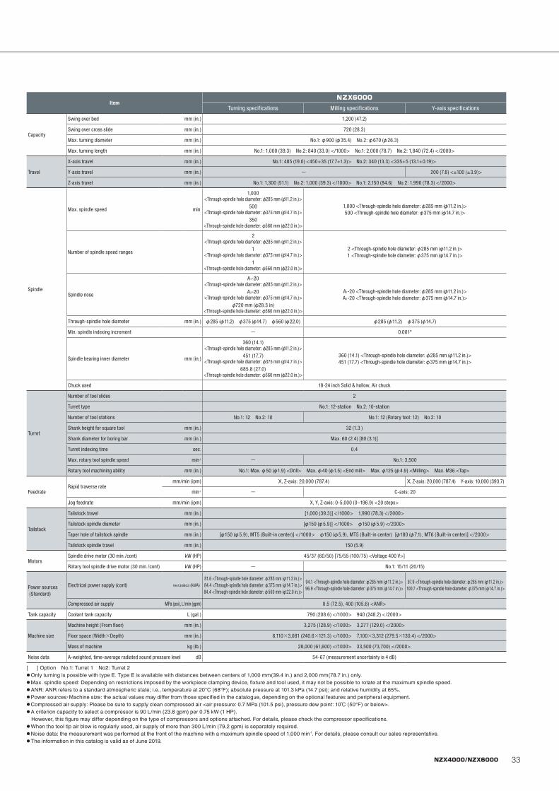
33NZX4000/NZX6000
ItemNZX6000
Turning specifications Milling specifications Y-axis specifications
Capacity
Swing over bed mm (in.) 1,200 (47.2)
Swing over cross slide mm (in.) 720 (28.3)
Max. turning diameter mm (in.) No.1: φ900 (φ35.4) No.2: φ670 (φ26.3)
Max. turning length mm (in.) No.1: 1,000 (39.3) No.2: 840 (33.0) </1000> No.1: 2,000 (78.7) No.2: 1,840 (72.4) </2000>
Travel
X-axis travel mm (in.) No.1: 485 (19.0) <450+35 (17.7+1.3)> No.2: 340 (13.3) <335+5 (13.1+0.19)>
Y-axis travel mm (in.) - 200 (7.8) <±100 (±3.9)>
Z-axis travel mm (in.) No.1: 1,300 (51.1) No.2: 1,000 (39.3) </1000> No.1: 2,150 (84.6) No.2: 1,990 (78.3) </2000>
Spindle
Max. spindle speed min-
1,000 <Through-spindle hole diameter: φ285 mm (φ11.2 in.)>
500 <Through-spindle hole diameter: φ375 mm (φ14.7 in.)>
350 <Through-spindle hole diameter: φ560 mm (φ22.0 in.)>
1,000 <Through-spindle hole diameter: φ285 mm (φ11.2 in.)>500 <Through-spindle hole diameter: φ375 mm (φ14.7 in.)>
Number of spindle speed ranges
2 <Through-spindle hole diameter: φ285 mm (φ11.2 in.)>
1 <Through-spindle hole diameter: φ375 mm (φ14.7 in.)>
1 <Through-spindle hole diameter: φ560 mm (φ22.0 in.)>
2 <Through-spindle hole diameter: φ285 mm (φ11.2 in.)>1 <Through-spindle hole diameter: φ375 mm (φ14.7 in.)>
Spindle nose
A1-20 <Through-spindle hole diameter: φ285 mm (φ11.2 in.)>
A2-20 <Through-spindle hole diameter: φ375 mm (φ14.7 in.)>
φ720 mm (φ28.3 in) <Through-spindle hole diameter: φ560 mm (φ22.0 in.)>
A1-20 <Through-spindle hole diameter: φ285 mm (φ11.2 in.)>A2-20 <Through-spindle hole diameter: φ375 mm (φ14.7 in.)>
Through-spindle hole diameter mm (in.) φ285 (φ11.2) φ375 (φ14.7) φ560 (φ22.0) φ285 (φ11.2) φ375 (φ14.7)
Min. spindle indexing increment - 0.001°
Spindle bearing inner diameter mm (in.)
360 (14.1) <Through-spindle hole diameter: φ285 mm (φ11.2 in.)>
451 (17.7) <Through-spindle hole diameter: φ375 mm (φ14.7 in.)>
685.8 (27.0) <Through-spindle hole diameter: φ560 mm (φ22.0 in.)>
360 (14.1) <Through-spindle hole diameter: φ285 mm (φ11.2 in.)>451 (17.7) <Through-spindle hole diameter: φ375 mm (φ14.7 in.)>
Chuck used 18-24 inch Solid & hollow, Air chuck
Turret
Number of tool slides 2
Turret type No.1: 12-station No.2: 10-station
Number of tool stations No.1: 12 No.2: 10 No.1: 12 (Rotary tool: 12) No.2: 10
Shank height for square tool mm (in.) 32 (1.3 )
Shank diameter for boring bar mm (in.) Max. 60 (2.4) [80 (3.1)]
Turret indexing time sec. 0.4
Max. rotary tool spindle speed min-1 - No.1: 3,500
Rotary tool machining ability mm (in.) No.1: Max. φ50 (φ1.9) <Drill> Max. φ40 (φ1.5) <End mill> Max. φ125 (φ4.9) <Milling> Max. M36 <Tap>
FeedrateRapid traverse rate
mm/min (ipm) X, Z-axis: 20,000 (787.4) X, Z-axis: 20,000 (787.4) Y-axis: 10,000 (393.7)
min-1 - C-axis: 20
Jog feedrate mm/min (ipm) X, Y, Z-axis: 0-5,000 (0–196.9) <20 steps>
Tailstock
Tailstock travel mm (in.) [1,000 (39.3)] </1000> 1,990 (78.3) </2000>
Tailstock spindle diameter mm (in.) [φ150 (φ5.9)] </1000> φ150 (φ5.9) </2000>
Taper hole of tailstock spindle mm (in.) [φ150 (φ5.9), MT5 (Built-in center)] </1000> φ150 (φ5.9), MT5 (Built-in center) [φ180 (φ7.1), MT6 (Built-in center)] </2000>
Tailstock spindle travel mm (in.) 150 (5.9)
MotorsSpindle drive motor (30 min./cont) kW (HP) 45/37 (60/50) [75/55 (100/75) <Voltage 400 V>]
Rotary tool spindle drive motor (30 min./cont) kW (HP) - No.1: 15/11 (20/15)
Power sources (Standard)
Electrical power supply (cont) I94130B03 (kVA)81.6 <Through-spindle hole diameter: φ285 mm (φ11.2 in.)>84.4 <Through-spindle hole diameter: φ375 mm (φ14.7 in.)>84.4 <Through-spindle hole diameter: φ560 mm (φ22.0 in.)>
94.1 <Through-spindle hole diameter: φ285 mm (φ11.2 in.)>96.9 <Through-spindle hole diameter: φ375 mm (φ14.7 in.)>
97.9 <Through-spindle hole diameter: φ285 mm (φ11.2 in.)>100.7 <Through-spindle hole diameter: φ375 mm (φ14.7 in.)>
Compressed air supply MPa (psi), L/min (gpm) 0.5 (72.5), 400 (105.6) <ANR>
Tank capacity Coolant tank capacity L (gal.) 790 (208.6) </1000> 940 (248.2) </2000>
Machine size
Machine height (From floor) mm (in.) 3,275 (128.9) </1000> 3,277 (129.0) </2000>
Floor space (Width×Depth) mm (in.) 6,110×3,081 (240.6×121.3) </1000> 7,100×3,312 (279.5×130.4) </2000>
Mass of machine kg (lb.) 28,000 (61,600) </1000> 33,500 (73,700) </2000>
Noise data A-weighted, time-average radiated sound pressure level dB 54-67 (measurement uncertainty is 4 dB)
[ ] Option No.1: Turret 1 No2: Turret 2● Only turning is possible with type E. Type E is available with distances between centers of 1,000 mm(39.4 in.) and 2,000 mm(78.7 in.) only.● Max. spindle speed: Depending on restrictions imposed by the workpiece clamping device, fixture and tool used, it may not be possible to rotate at the maximum spindle speed.● ANR: ANR refers to a standard atmospheric state; i.e., temperature at 20°C (68°F); absolute pressure at 101.3 kPa (14.7 psi); and relative humidity at 65%.● Power sources・Machine size: the actual values may differ from those specified in the catalogue, depending on the optional features and peripheral equipment.● Compressed air supply: Please be sure to supply clean compressed air <air pressure: 0.7 MPa (101.5 psi), pressure dew point: 10℃ (50°F) or below>. ● A criterion capacity to select a compressor is 90 L/min (23.8 gpm) per 0.75 kW (1 HP). However, this figure may differ depending on the type of compressors and options attached. For details, please check the compressor specifications.● When the tool tip air blow is regularly used, air supply of more than 300 L/min (79.2 gpm) is separately required.● Noise data: the measurement was performed at the front of the machine with a maximum spindle speed of 1,000 min-1. For details, please consult our sales representative.● The information in this catalog is valid as of June 2019.
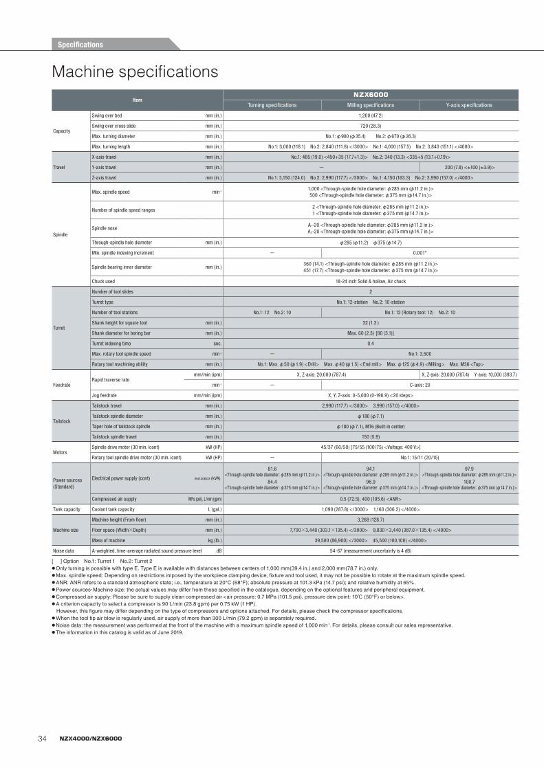
34 NZX4000/NZX6000
Machine specificationsItem
NZX6000
Turning specifications Milling specifications Y-axis specifications
Capacity
Swing over bed mm (in.) 1,200 (47.2)
Swing over cross slide mm (in.) 720 (28.3)
Max. turning diameter mm (in.) No.1: φ900 (φ35.4) No.2: φ670 (φ26.3)
Max. turning length mm (in.) No.1: 3,000 (118.1) No.2: 2,840 (111.8) </3000> No.1: 4,000 (157.5) No.2: 3,840 (151.1) </4000>
Travel
X-axis travel mm (in.) No.1: 485 (19.0) <450+35 (17.7+1.3)> No.2: 340 (13.3) <335+5 (13.1+0.19)>
Y-axis travel mm (in.) - 200 (7.8) <±100 (±3.9)>
Z-axis travel mm (in.) No.1: 3,150 (124.0) No.2: 2,990 (117.7) </3000> No.1: 4,150 (163.3) No.2: 3,990 (157.0) </4000>
Spindle
Max. spindle speed min-11,000 <Through-spindle hole diameter: φ285 mm (φ11.2 in.)>500 <Through-spindle hole diameter: φ375 mm (φ14.7 in.)>
Number of spindle speed ranges2 <Through-spindle hole diameter: φ285 mm (φ11.2 in.)>1 <Through-spindle hole diameter: φ375 mm (φ14.7 in.)>
Spindle noseA1-20 <Through-spindle hole diameter: φ285 mm (φ11.2 in.)>A2-20 <Through-spindle hole diameter: φ375 mm (φ14.7 in.)>
Through-spindle hole diameter mm (in.) φ285 (φ11.2) φ375 (φ14.7)
Min. spindle indexing increment - 0.001°
Spindle bearing inner diameter mm (in.)360 (14.1) <Through-spindle hole diameter: φ285 mm (φ11.2 in.)>451 (17.7) <Through-spindle hole diameter: φ375 mm (φ14.7 in.)>
Chuck used 18-24 inch Solid & hollow, Air chuck
Turret
Number of tool slides 2
Turret type No.1: 12-station No.2: 10-station
Number of tool stations No.1: 12 No.2: 10 No.1: 12 (Rotary tool: 12) No.2: 10
Shank height for square tool mm (in.) 32 (1.3 )
Shank diameter for boring bar mm (in.) Max. 60 (2.3) [80 (3.1)]
Turret indexing time sec. 0.4
Max. rotary tool spindle speed min-1 - No.1: 3,500
Rotary tool machining ability mm (in.) No.1: Max. φ50 (φ1.9) <Drill> Max. φ40 (φ1.5) <End mill> Max. φ125 (φ4.9) <Milling> Max. M36 <Tap>
FeedrateRapid traverse rate
mm/min (ipm) X, Z-axis: 20,000 (787.4) X, Z-axis: 20,000 (787.4) Y-axis: 10,000 (393.7)
min-1 - C-axis: 20
Jog feedrate mm/min (ipm) X, Y, Z-axis: 0-5,000 (0-196.9) <20 steps>
Tailstock
Tailstock travel mm (in.) 2,990 (117.7) </3000> 3,990 (157.0) </4000>
Tailstock spindle diameter mm (in.) φ180 (φ7.1)
Taper hole of tailstock spindle mm (in.) φ180 (φ7.1), MT6 (Built-in center)
Tailstock spindle travel mm (in.) 150 (5.9)
MotorsSpindle drive motor (30 min./cont) kW (HP) 45/37 (60/50) [75/55 (100/75) <Voltage: 400 V>]
Rotary tool spindle drive motor (30 min./cont) kW (HP) - No.1: 15/11 (20/15)
Power sources(Standard)
Electrical power supply (cont) I94130B03 (kVA)
81.6 <Through-spindle hole diameter: φ285 mm (φ11.2 in.)>
84.4 <Through-spindle hole diameter: φ375 mm (φ14.7 in.)>
94.1 <Through-spindle hole diameter: φ285 mm (φ11.2 in.)>
96.9 <Through-spindle hole diameter: φ375 mm (φ14.7 in.)>
97.9 <Through-spindle hole diameter: φ285 mm (φ11.2 in.)>
100.7 <Through-spindle hole diameter: φ375 mm (φ14.7 in.)>
Compressed air supply MPa (psi), L/min (gpm) 0.5 (72.5), 400 (105.6) <ANR>
Tank capacity Coolant tank capacity L (gal.) 1,090 (287.8) </3000> 1,160 (306.2) </4000>
Machine size
Machine height (From floor) mm (in.) 3,268 (128.7)
Floor space (Width×Depth) mm (in.) 7,700×3,440 (303.1×135.4) </3000> 9,830×3,440 (387.0×135.4) </4000>
Mass of machine kg (lb.) 39,500 (86,900) </3000> 45,500 (100,100) </4000>
Noise data A-weighted, time-average radiated sound pressure level dB 54-67 (measurement uncertainty is 4 dB)
[ ] Option No.1: Turret 1 No.2: Turret 2● Only turning is possible with type E. Type E is available with distances between centers of 1,000 mm(39.4 in.) and 2,000 mm(78.7 in.) only.● Max. spindle speed: Depending on restrictions imposed by the workpiece clamping device, fixture and tool used, it may not be possible to rotate at the maximum spindle speed.● ANR: ANR refers to a standard atmospheric state; i.e., temperature at 20°C (68°F); absolute pressure at 101.3 kPa (14.7 psi); and relative humidity at 65%.● Power sources・Machine size: the actual values may differ from those specified in the catalogue, depending on the optional features and peripheral equipment.● Compressed air supply: Please be sure to supply clean compressed air <air pressure: 0.7 MPa (101.5 psi), pressure dew point: 10℃ (50°F) or below>. ● A criterion capacity to select a compressor is 90 L/min (23.8 gpm) per 0.75 kW (1 HP). However, this figure may differ depending on the type of compressors and options attached. For details, please check the compressor specifications.● When the tool tip air blow is regularly used, air supply of more than 300 L/min (79.2 gpm) is separately required.● Noise data: the measurement was performed at the front of the machine with a maximum spindle speed of 1,000 min-1. For details, please consult our sales representative.● The information in this catalog is valid as of June 2019.
Specifications

NZX4060_EB01V_FORM.indd 6 2019/06/04 13:36

DMG MORI CO., LTD.
Nagoya Head Office □ 2-35-16 Meieki, Nakamura-ku, Nagoya City, Aichi 450-0002, Japan Phone: +81-52-587-1811Tokyo Global Headquarters □ 2-3-23, Shiomi, Koto-ku, Tokyo 135-0052, Japan Phone: +81-3-6758-5900
Iga Campus □ 201 Midai, Iga City, Mie 519-1414, Japan Phone: +81-595-45-4151Nara Campus □ 362 Idono-cho, Yamato-Koriyama City, Nara 639-1183, Japan Phone: +81-743-53-1121
<Precautions for Machine Relocation>
EXPORTATION:All contracts are subject to export permit by the Government of Japan. Customer shall comply with the laws and regulations of the exporting country governing the exportation or re-exportation of the Equipment, including but not limited to the Export Administration Regulations. The Equipment is subject to export restrictions imposed by Japan and other exporting countries and the Customer will not export or permit the export of the Equipment anywhere outside the exporting country without proper government authorization. To prevent the illegal diversion of the Equipment to individuals or nations that threaten international security, it may include a “Relocation Machine Security Function” that automatically disables the Equipment if it is moved following installation. If the Equipment is so-disabled, it can only be re-enabled by contacting DMG MORI or its distributor representative. DMG MORI and its distributor representative may refuse to re-enable the Equipment if it determines that doing so would be an unauthorized export of technology or otherwise violates applicable export restrictions. DMG MORI and its distributor representative shall have no obligation to re-enable such Equipment. DMG MORI and its distributor representative shall have no liability (including for lost profits or business interruption or under the limited service warranty included herein) as a result of the Equipment being disabled.
+ DCG, DDM, BMT, ORC, compactMASTER, CELOS, ERGOline, COMPACTline, DMG MORI SMARTkey and DMG MORI gearMILL are trademarks or registered trademarks of DMG MORI CO., LTD. in Japan, the USA and other countries.
+ If you have any questions regarding the content, please consult our sales representative.
+ The information in this catalog is valid as of June 2019. Designs and specifications are subject to changes without notice.
+ The machines shown in the catalog may differ from the actual machines. The location and the size of the nameplates may also differ from the actual machines, or the nameplates may not be attached to some machines.
+ DMG MORI is not responsible for differences between the information in the catalog and the actual machine.
NZX4060-EB01VV.1907.CDT.0000Created in Japan