NYOMAN PRAMAITA A thesis submitted in partial fulfilment...
121
HYBRID ORTHOGONAL CODE SEQUENCES FOR HIGH–DENSITY SYNCHRONOUS CDMA SYSTEMS NYOMAN PRAMAITA A thesis submitted in partial fulfilment of the requirements of Liverpool John Moores University for the degree of Doctor of Philosophy August 2014
Transcript of NYOMAN PRAMAITA A thesis submitted in partial fulfilment...

HYBRID ORTHOGONAL CODE SEQUENCES
FOR HIGH–DENSITY SYNCHRONOUS
CDMA SYSTEMS
NYOMAN PRAMAITA
A thesis submitted in partial fulfilment of the
requirements of Liverpool John Moores University
for the degree of Doctor of Philosophy
August 2014

i
HYBRID ORTHOGONAL CODE SEQUENCES
FOR HIGH–DENSITY SYNCHRONOUS
CDMA SYSTEMS
by
Nyoman Pramaita
Liverpool John Moores University
Abstract
One of the primary tasks of the mobile system designers in order to support high
density of devices in a CDMA system is to create a code sequence with a capacity
for large number of spreading code sequences having low cross-correlation values
between them, in order to ensure accommodation of large number of users and to
minimise the effect of multiple access interference.
In this research, the design for a novel hybrid orthogonal very large set
(HOVLS) code sequence is proposed for high density mobile application scenarios.
The design and development of both fixed and variable spreading factor code
sequences are presented in this thesis. Both type of code sequences have been
implemented via simulation using Matlab/Simulink. The performance of the code
sequences has been evaluated and compared with that of existing code sequences.
The proposed code sequences are more advantageous for high density mobile
networks. The unique feature of the fixed length HOVLS code sequence is that its
ACF, CCF, and BER performances are similar to that of orthogonal Gold code
sequence and orthogonal m-sequence under Rayleigh flat and frequency selective
fading channel conditions while having a significantly higher capacity than those
orthogonal code sequences. The proposed HOVLS code sequence could support 134

ii
different cells which is more than twice than that of orthogonal Gold code sequence
and orthogonal m-sequence. To the knowledge of the author, this is the largest
reported family size in the literature for an orthogonal code sequence for CDMA
applications.
In order to support variable data rate, fixed length HOVLS code sequence was
developed into orthogonal variable spreading factor code sequence. It is shown that
the proposed OVSF code sequence has slightly better CCF than those of OVSF Gold
code sequence and m-sequence in terms of CM (correlation margin). The ACF of the
proposed OVSF code sequence is similar to those of OVSF Gold code sequence and
m-sequence. The proposed OVSF code sequence possesses comparable BER
performance to those of orthogonal Gold code sequence and orthogonal m-sequence
under flat fading channel condition. Whereas, the BER performance of the proposed
OVSF code sequence is slightly better than that of Gold code sequence and OVSF
m-sequence under frequency selective fading channel.
Therefore, the proposed HOVLS code sequence is appropriate code sequence in
CDMA systems than those of orthogonal Gold code sequence and orthogonal m-
sequence for both fixed and variable rate high density network applications.
iii
Acknowledgements
I would like to express the deepest gratitude to my supervisor Dr. Princy
Johnson. Her guidance, support, patient advice and encouragment were very
valuable throughout my research studies.
I would like to thank all members of LJMU staff for their helpul comments and
general enthusiasm to the author.
I also appreciate the finacial support from DGHE scholarship for this Ph.D
program.
Last but not least, my genuine appreciation to my parents, my wife and my kids,
my brother and sisters, and all my family for their support and encouragment to
complete my research studies.

iv
Table of Contents
Abstract .........................................................................................................................i
Acknowledgements ....................................................................................................iii
Table of Contents ........................................................................................................iv
List of Figures .............................................................................................................ix
List of Tables .............................................................................................................xii
Acronyms ..................................................................................................................xiii
Chapter 1 INTRODUCTION .......................................................................................1
1.1 Background ............................................................................................................1
1.2 Motivation ..............................................................................................................2
1.3 Aim and Objectives ................................................................................................4
1.4 Contribution ...........................................................................................................4
1.5 Thesis Layout .........................................................................................................5
Chapter 2 LITERATURE REVIEW ON SPREADING CODE SEQUENCES .........6
2.1 Literature Review on Non-Orthogonal Spreading Code Sequences ......................7
2.2 Literature Review on Orthogonal Spreading Code Sequences ........................... ...9
Chapter 3 SPREADING CODE SEQUENCES AND SYNCHRONOUS
CDMA SYSTEMS ....................................................................................................12
3.1 Correlation Properties of Spreading Code Sequence .........................................13
3.1.1 Autocorrelation function ...........................................................................13
3.1.2 Cross-correlation function .........................................................................13
3.2 Non-orthogonal Spreading Code Sequences ......................................................14
3.2.1 Maximal-length sequence ..........................................................................14
3.2.2 Gold code sequence ...................................................................................15

v
3.2.3 Small set Kasami code sequence ...............................................................16
3.2.4 Large set Kasami code sequence .............................................................. .17
3.3 Orthogonal Code Sequence ............................................................................... 17
3.3.1 Walsh code sequence .................................................................................17
3.3.2 Orthogonal Gold code sequence ................................................................18
3.3.3 Orthogonal m-sequence .............................................................................18
3.3.4 Orthogonal Small set Kasami code sequence ............................................20
3.3.5 Orthogonal variable spreading factor code sequence ................................20
3.4 Synchronous CDMA System .............................................................................23
3.4.1 Differential binary phase shift keying (DBPSK) symbol ………………..24
3.5 Performance Metric ………………………………………………………........25
3.5.1 Bit error rate ……………………………………………………………...25
Chapter 4 COMMUNICATION CHANNEL ...........................................................27
4.1 AWGN Channel ..................................................................................................27
4.2 Fading Channel ....................................................................................................28
4.2.1 Flat fading channel .....................................................................................29
4.2.2 Frequency selective fading channel ...........................................................31
Chapter 5 DESIGN, IMPLEMENTATION AND ANALYSIS OF
FIXED SPREADING FACTOR HYBRID ORTHOGONAL VERY
LARGE SET CODE SEQUENCE ............................................................................33
5.1 Design of HOVLS Code Sequence .....................................................................33
5.1.1 A Novel method to generate very large set of orthogonal
code sequence ……………………………………………………………36
5.2 Implementation and Analysis of The Proposed HOVLS
Code Sequence …………………………………………………………………42

vi
5.2.1 Simulation of the proposed HOVLS code sequence …………………….42
5.2.1.1 Block diagram of the synchronous CDMA system ……...............42
5.2.1.2 Assumptions for the simulation of the synchronous
CDMA system …………………………………………………...43
5.2.2 Simulation results and discussion ………………………………………..44
5.2.2.1 Capacity and peak cross-correlation value of the proposed
HOVLS code sequence …………………………………….........45
5.2.2.2 Autocorrelation function of the proposed
HOVLS code sequence ………………………………………….45
5.2.2.3 Cross-correlation function of the proposed
HOVLS code sequence …………………………………………48
5.2.2.4 BER performance of the proposed HOVLS code sequence
under Rayleigh flat fading channel condition …………………..51
5.2.2.5 BER performance of the proposed HOVLS code sequence
under Rayleigh frequency selective fading
channel condition ……………………………………………….53
Chapter 6 DESIGN, IMPLEMENTATION AND ANALYSIS OF
VARIABLE SPREADING FACTOR HYBRID ORTHOGONAL
VERY LARGE SET CODE SEQUENCE ................................................................56
6.1 Design of The Proposed OVSF HOVLS Code Sequence ……………………..57
6.2 Implementation and Analysis of The Proposed OVSF HOVLS
Code Sequence …………………………………………………………………59
6.2.1 Simulation of the proposed OVSF HOVLS code sequence ……………..60
6.2.1.1 Scenario for simulation of the proposed OVSF HOVLS
code sequence ……………………………………………...........60
vii
6.2.1.2 Simulation assumptions for the proposed OVSF HOVLS
Code sequence of synchronous CDMA system ……………......61
6.2.2 Simulation results and discussions ………………………………………62
6.2.2.1 Autocorrelation function of the proposed OVSF HOVLS
code sequence …………………………………………………...63
6.2.2.2 Cross-correlation function of the proposed OVSF HOVLS
code sequence in same groups in the code tree …………………67
6.2.2.3 Cross-correlation function of the proposed OVSF HOVLS
code sequence from different groups in the code tree …………..71
6.2.2.4 BER performance of the proposed OVSF HOVLS code
sequence under Rayleigh flat fading channel ……………….......72
6.2.2.5 BER performance of the proposed OVSF HOVLS code
sequence under Rayleigh frequency selective
fading channel for user 2R ……………………………………...75
6.2.2.6 BER performance of the proposed OVSF HOVLS code
sequence under Rayleigh frequency selective
fading channel for user R ………………………………………..78
6.2.2.7 Comparison of BER performance of the proposed OVSF
HOVLS code sequence between user 2R and user R
under Rayleigh frequency selective fading channel …………….80
Chapter 7 CONCLUSION AND FUTURE WORK ..................................................84
REFERENCES ..........................................................................................................88
LIST OF CONFERENCES AND JOURNAL SUBMITTED ..................................92
APPENDICES ...........................................................................................................93
A. The Code Tree for Generation of OVSF Gold Code Sequence

viii
and OVSF m-Sequence ………………………………………………………….93
B. Notation of OVSF Gold Code Sequence and OVSF m-Sequence
in The Code Tree ………………………………………………………………...96
C. Matlab Code and Simulink for The Proposed Code Sequence ………………….99

ix
List of Figures
Figure 3.1 Algorithm for generation of orthogonal small set Kasami code
Sequences ………………………………………………………….. 21
Figure 3.2 Code tree for generation of OVERSUSF code sequences ………. 22
Figure 4.1 The additive white gaussian noise channel .................................. 28
Figure 4.2 Flat fading channel characteristics ………………………………… 30
Figure 4.3 Frequency selective fading channel characteristics ………………. 31
Figure 5.1 Block diagram for the simulation of synchronous CDMA
System ……………………………………………………………… 43
Figure 5.2 ACF of the proposed HOVLS code sequence …………………….. 47
Figure 5.3 ACF of orthogonal Gold code sequence ………………………….. 47
Figure 5.4 ACF of orthogonal m-sequence …………………………………… 48
Figure 5.5 CCF of the proposed HOVLS code sequence …………………….. 50
Figure 5.6 CCF of orthogonal Gold code sequence …………………………… 50
Figure 5.7 CCF of orthogonal m-sequence ……………………………………. 51
Figure 5.8 BER versus SNR of the orthogonal code sequences under
Rayleigh flat fading channel ………………………………… ………52
Figure 5.9 BER versus SNR of the orthogonal code sequences under
Rayleigh frequency selective fading channel …………………….. 54
Figure 5.10 BER versus number of users of the orthogonal code sequences
for SNR = 10 dB under Rayleigh frequency selective
fading channel ……………………………………………………… 54
Figure 6.1 Code sequence tree for generation of OVSF HOVLS
code sequences …………………………………………………….. 58

x
Figure 6.2 ACF of the proposed OVSF HOVLS code sequence
for 128 chip lengths ……………………………………………….. 64
Figure 6.3 ACF of OVSF Gold code sequence for 128 chip lengths ………… 64
Figure 6.4 ACF of OVSF m-sequence for 128 chip lengths …………………. 65
Figure 6.5 ACF of the proposed OVSF HOVLS code sequence
for 256 chip lengths ……………………………………………….. 65
Figure 6.6 ACF of OVSF Gold code sequence for 256 chip lengths ………… 66
Figure 6.7 ACF of OVSF m-sequence for 256 chip lengths …………………. 66
Figure 6.8 CCF of the proposed OVSF HOVLS code sequence in
the same groups in the code tree for 128 chip lengths …………… 68
Figure 6.9 CCF of OVSF Gold code sequence in the same groups in
the code tree for 128 chip lengths ………………………………… 69
Figure 6.10 CCF of OVSF m-sequence in the same groups in
the code tree for 128 chip lengths ………………………………… 69
Figure 6.11 CCF of the proposed OVSF HOVLS code sequence in
the same groups in the code tree for 256 chip lengths …………… 70
Figure 6.12 CCF of OVSF Gold code sequence in the same groups in
the code tree for 256 chip lengths ………………………………… 70
Figure 6.13 CCF of OVSF m-sequence in the same groups in
the code tree for 256 chip lengths …………………………………. 71
Figure 6.14 BER versus SNR of the OVSF code sequences under
Rayleigh flat fading channel for user 2R …………………………. 74
Figure 6.15 BER versus SNR of the OVSF code sequences under
Rayleigh flat fading channel for user R …………………………… 74
Figure 6.16 BER versus SNR of the OVSF code sequences

xi
under Rayleigh frequency selective fading channel
for user 2R ………………………………………………………….. 76
Figure 6.17 BER versus number of users of the OVSF code
sequences under Rayleigh frequency selective fading
channel for SNR = 10 dB for user 2R …………………………….. 77
Figure 6.18 BER versus SNR of the OVSF code sequences
under Rayleigh frequency selective fading channel
for user R …………………………………………………………… 79
Figure 6.19 BER versus number of users of the OVSF code
sequences under Rayleigh frequency selective fading
channel for SNR = 10 dB for user R ……………………………… 79
Figure 6.20 BER versus SNR of the proposed OVSF HOVLS code
sequence under Rayleigh frequency selective fading
channel between 16 user 2Rs and 16 user Rs …………………….. 81
Figure 6.21 BER versus SNR of OVSF Gold code sequence
under Rayleigh frequency selective fading channel
between 16 user 2Rs and 16 user Rs ……………………………… 81
Figure 6.22 BER versus SNR of OVSF m-sequence under
Rayleigh frequency selective fading channel
between 16 user 2Rs and 16 user Rs ………………………………. 82

xii
List of Tables
Table 3.1 Encoding and decoding operation of DBPSK symbol ……………… 25
Table 5.1 Capacity and peak cross-correlation value of the proposed
and selected orthogonal code sequences ……………………………. 45
Table 5.2 Merit factor of the proposed HOVLS code sequence ……………… 46
Table 5.3 CM of the proposed HOVLS code sequence ……………………….. 49
Table 6.1 MF of the proposed OVSF HOVLS code sequence ………………… 63
Table 6.2 CM of the proposed OVSF HOVLS code sequence ……………….. 68
xiii
Acronyms
AWGN Additive white gaussian noise
ACF Autocorrelation function
BER Bit error rate
CCF Cross-correlation function
CM Correlation margin
CDMA Code division multiple access
DS-CDMA Direct-sequence code division multiple access
HOVLS Hybrid orthogonal very large set
ISI Intersymbol interference
MAI Multiple access interference
MF Merit figure
OVSF Orthogonal variable spreading factor
SF Spreading factor
SNR Sinal to noise ratio
WCDMA Wide band code division multiple access
1
Chapter 1
INTRODUCTION
1.1 Background
Spread spectrum signals for digital communication were originally developed
and used for military communication either (1) to provide resistance to hostile
jamming, (2) to hide a signal by transmitting it at low power and thus, making it
difficult for an unintended listeners to detect its presence in noise, or (3) to make it
possible for multi user to communicate through the same channel. Today, however
spread spectrum signals are being used for commercial applications including
vehicular communications and interoffice wireless communications (Proakis and
Salehi, 1998).
Spread spectrum can be defined as a transmission technique using code
sequences having bit rate much higher than that of the information signal. The effect
of this is to significantly increase the bandwidth of the signal to be transmitted. This
transformation is called spreading and the code sequence used to spread the
information signal is known as spreading code sequence. The term chip rate is used
to describe the rate of the spreading code sequence while the term symbol rate is
used to represent the rate of information signal (Fazel and Kaiser, 2008).
Each end user terminal has its own spreading code sequence. The identical
spreading code sequence is used in both transformations on each end of radio
channel, spreading the original signal, producing wideband signal, and despreading
wide band signal back to the original narrowband signal (Korhonen, 2001).
Code division multiple access (CDMA) system is one of the applications based
on spread spectrum requiring a unique spreading code sequence for each user

2
(Hoshyar, et.al, 2008; Cheng, et.al., 2009; Nikjah and Beaulieu, 2008). In a
synchronous CDMA system or in the downlink of a mobile network, a signal
transmitted by the base station will contain the component intended for the desired
user and parts of components intended for other users sharing the same frequency in
the cell. From the perspective of the desired user, the signal components intended for
other users contribute to noise components known as multiple access interference
(MAI) (Jatunov and Madisetti, 2006; Van-Houtum, 2001). This MAI arising from
the cross-correlation between the spreading code sequences assigned to different
users, limits the performance of a CDMA based wireless system under multiple
access interference limited channel conditions (Adeola, et.al, 2011).
There is a growing need for the design of mobile networks that support high
density of devices, for example users of national mobile networks in urban areas, in a
CDMA system. One of the primary objectives of the mobile system designers in this
case is to create a code sequence with a capacity for large number of spreading code
sequences having low cross-correlation values between them, in order to ensure
accommodation of large number of users and to minimise the effect of multiple
access interference (Kedia, et.al, 2010).
In this research, the design of hybrid orthogonal very large set (HOVLS) code
sequence is proposed to minimise the effect of MAI and accommodate larger number
of users. In order to support variable data rate, fixed spreading factor HOVLS code
sequence was developed into orthogonal variable spreading factor code sequence.
1.2 Motivation
Binary spreading code sequence can be divided into two categories, namely,
orthogonal and non-orthogonal code sequences. Walsh code sequence has proven its

3
existence as a popular orthogonal code sequence, whereas m-sequence, Gold and
Kasami code sequences have established themselves as popular non-orthogonal
binary code sequences (Pal and Chattopadhyay, 2010; Akansu and Poluri, 2007).
There are orthogonal spreading code sequences that are created from non-
orthogonal spreading code sequences, namely orthogonal Gold code sequence which
is generated from non-orthogonal Gold code sequence (Tachikawa, 1992) and
orthogonal m-sequence which is generated from non-orthogonal m-sequence
(Donelan and O‟Farrell, 1999). These orthogonal spreading code sequences have
large family size and can minimise the effect of multiple access interference under
flat fading channel condition; however the effect of multiple access interference
under frequency selective fading channel condition is worse than that of under flat
fading channel condition.
Recently, Chandra and Chattopadhyay in 2009 demonstrated that non-
orthogonal small set Kasami code sequence can be converted into orthogonal code
sequence, however this orthogonal small set Kasami code sequence only possesses a
small family of code sequences compared to the orthogonal Gold code sequence and
orthogonal m-sequence.
This research work gets inspiration from the research works described above,
and proposes hybrid orthogonal very large set code sequence that minimises the
effect of multiple access interference and has a very large family size to
accommodate large number of users. This hybrid orthogonal very large set (HOVLS)
code sequence is generated from two different non-orthogonal code sequences,
namely non-orthogonal m-sequence and large set Kasami code sequence.

4
1.3 Aim and Objectives
The aim of this research is to design very large sets of orthogonal fixed and
variable spreading factor code sequences for multi user wireless mobile networks
based CDMA systems and to evaluate their performance against other orthogonal
code sequences namely orthogonal Gold and orthogonal m-sequences.
The objectives of this proposed research can be summarised as follows:
1. To design orthogonal code sequence for CDMA applications
2. To develop the orthogonal code sequence into orthogonal variable length
code sequence for wide band application
3. To evaluate the performance of the proposed orthogonal fixed spreading
factor code sequence including auto-correlation function (ACF), cross-
correlation function (CCF) and bit error rate (BER) under various channel
conditions namely Rayleigh flat and frequency selective fading channels.
4. To evaluate the performance of the proposed orthogonal variable spreading
factor code sequence against the metrics such as CCF and ACF and BER
under Rayleigh flat and frequency selective fading channels.
1.4 Contribution
In this research work, hybrid orthgonal code sequences have been designed for
fixed and variable spreading factor. It has been shown that for fixed spreading factor,
the proposed code sequence has comparable ACF, CCF, and BER performance under
flat and frequency selective fading channel conditions to those of orthogonal Gold
code sequence and orthogonal m-sequence; however family size of the proposed
code sequence is much larger (more than twice) than that of orthogonal Gold code
sequence and orthogonal m-sequence.

5
BER performance of the proposed code sequence for variable spreading factor is
comparable to those of orthogonal Gold code sequence and orthogonal m-sequence
under flat fading channel condition. However, the proposed orthogonal variable
spreading factor (OVSF) code sequence has slightly better BER performance than
those of OVSF Gold code sequence and m-sequence under frequency selective
fading channel condition.
Besides, the proposed OVSF code sequence has slightly better CCF than those
of OVSF Gold code sequence and m-sequence in terms of CM (correlation margin),
however ACF of the proposed OVSF code sequence is similar to those of OVSF
Gold and m-sequences.
1.5 Thesis Layout
The layout of this PhD thesis is as follows: Chapter 1 shows an introduction of
this research work. Literature review on spreading code sequences is presented in
Chapter 2. Chapter 3 presents non-orthogonal and orthogonal spreading code
sequences and CDMA systems. AWGN, flat and frequency selective fading channels
used to evaluate BER performance of the spreading code sequences are presented in
Chapter 4. Chapter 5 presents the design and evaluation of fixed spreading factor
hybrid orthogonal very large set code sequence. Chapter 6 presents the design and
evaluation of variable spreading factor hybrid orthogonal very large set code
sequence. Conclusion and future work are presented in Chapter 7. Finally, references
and appendices are included.

6
Chapter 2
LITERATURE REVIEW ON SPREADING CODE SEQUENCES
Binary spreading code sequence can be divided into two categories, i.e.
orthogonal and non-orthogonal code sequences. Each of these spreading code
sequences has its own unique parameter including autocorrelation, cross-correlation,
and family size or number of different spreading code sequences in a chip set
(Mollah and Islam, 2012).
When the cross-correlation value between any two spreading code sequences
from same chip set is not zero, spreading code sequences in that chip set are called
non-orthogonal code sequences. While orthogonal code sequences have zero cross-
correlation value between any two spreading code sequences from same chip set
(Ziani and Medouri, 2012).
Maximal-sequence (m-sequence), Gold and Kasami code sequences (three
families of binary spreading code sequences) have established themselves as popular
non-orthogonal binary code sequences. Walsh code sequence, which is generated by
mapping code word rows of special square matrices called Hadamard matrices has
proven its existence as a popular orthogonal code sequence (Pal and Chattopadhyay,
2010; Dinan and Jabbari, 1998). However, orthogonal Gold code sequence,
orthogonal m-sequence, and orthogonal small set Kasami code sequence are
orthogonal code sequences generated from their non-orthogonal counter parts
(Tachikawa, 1992; Chandra and Chattopadhyay, 2009; Donelan and O‟Farrell,
1999).
The orthogonal spreading code sequence used in the code division multiple
access (CDMA) and wideband CDMA systems could be divided into fixed-length

7
and variable-length orthogonal code sequences respectively (Dinan and Jabbari,
1998).
2.1 Literature Review on Non-Orthogonal Spreading Code Sequences
According to (Golomb, 1967) the theory of maximal-sequence (m-sequence)
was developed. As the name suggests, these are precisely the code sequences of
maximum possible period (which is ) from n-stage binary shift register
with linear feedback. These code sequences possess ideal autocorrelation function
(ACF) close to the noise impulse function property, i.e. it can take only two values,
N and -1. However, the code sequences have poor cross-correlation function (CCF)
and do not have a large family size. Therefore, these code sequences are inadequate
for spread spectrum multiple access communication application requiring much
larger number of code sequences and low cross-correlation values to accommodate
larger number of user and mitigate the effect of multiple access interference (MAI)
respectively.
One important class of periodic code sequences which provides large number of
code sequences with good cross-correlation function is Gold code sequence.
Therefore, Gold code sequences are more appropriate to be implemented in
applications such as spread spectrum multiple access communications in that they
can mitigate the effect of MAI and accommodate a large number of users. However,
the autocorrelation function of Gold code sequences is not as good as that of the m-
sequences, therefore synchronisation at the receiver will be more difficult. These
code sequences were proposed by Gold in the late 1960‟s (Gold, 1968).
Kasami code sequence proposed by Kasami (1966) can be divided into small set
and large set Kasami code sequences. Small set Kasami code sequence sets are one
of the important types of binary code sequence sets as they are able to mitigate the

8
effect of MAI in multi user applications due to their very low cross-correlation
values. However, this code sequence generates the smallest number of code
sequences compared to any other binary spreading code sequence, therefore small set
Kasami code sequence is not appropriate for large number of users within the spread
spectrum multiple access communications environment. The autocorrelation function
(ACF) of small set Kasami code sequence is better than that of Gold code sequence,
however is worse than that of m-sequence, and hence synchronisation is more
difficult at the receiver than that of m-sequence due to more than two values in the
autocorrelation function unlike m-sequence. The point in time, when the receiver can
detect sufficiently high signal strength indicates that the starting point of the code
sequence is found or synchronised.
Small set Kasami code sequences have better correlation properties compared to
Gold code sequences. However, the family size contains less number of code
sequences. The number of code sequences can be increased by making some
relaxation on the correlation values of the code sequences. The new set of code
sequences is called large set Kasami code sequences. These code sequences have the
largest family size among binary spreading code sequence. However, autocorrelation
and cross-correlation properties are the worst for the code sequence. These code
sequences can be implemented in CDMA system or any other multi-user
communication system that needs to accommodate a large number of users.
However, due to the high value of cross-correlation between the code sequences, the
contribution to the effect of MAI by these codes will be significant.

9
2.2 Literature Review on Orthogonal Spreading Code Sequences
Walsh code sequences are obtained from the Hadamard matrix which is a square
matrix where each row in the matrix is orthogonal to all other rows, and each column
in the matrix is orthogonal to all other columns (Thompson et.al., 1986). Each
column or row in the Hadamard matrix corresponds to a Walsh code sequence of
length . These code sequences are used in synchronous downlink CDMA systems.
They can maintain orthogonality (zero cross-correlation function) and thus cause
zero MAI in CDMA systems. Even though these code sequences can maintain
orthogonality, since the length of the code sequence is directly related to the family
size of the code sequence, when the demand from more users arises in CDMA
systems, these code sequences are not effective in accommodating those large
number of users. Also, ACF of Walsh code sequence is not impulsive, therefore
synchronisation is more difficult at the receiver.
Orthogonal spreading code sequence proposed in (Tachikawa, 1992) is
generated from non-orthogonal Gold code sequence. This orthogonal code sequence
has larger number of distinct code sequences than that of Walsh code sequence.
Orthogonal Gold code sequence has (length of non-orthogonal Gold code
sequence) groups where each group has members of length chips.
For same length of code sequence, orthogonal Gold code sequence has much more
number of distinct code sequences than that of Walsh code sequence, however CCF
of orthogonal Gold code sequence is not zero in any group. Moreover, any member
in a group of orthogonal Gold code sequences is not orthogonal to other members in
other groups. Therefore, orthogonal Gold code sequence is not adequate to minimize
the effect of multiple access interference in CDMA systems. However,

10
synchronisation of orthogonal Gold code sequence at the receiver is easier than that
of Walsh code sequence, due to impulsive ACF of orthogonal Gold code sequence.
H. Donelan and T. O‟Farrell in 1999 proposed a method to generate sets of
orthogonal code sequences. This orthogonal code sequence is generated using two
different non-orthogonal m-sequences. The total number of code sequence sets and
distinct code sequences can be generated are (length of non-orthogonal m-
sequence) and respectively, thus orthogonal m-sequence has similar
number of different code sequences to that of orthogonal Gold code sequence, but
much more number of different code sequences to that of Walsh code sequence for
same code length. This orthogonal m-sequence possesses an impulsive ACF similar
to that of orthogonal Gold code sequence, therefore synchronisation of orthogonal m-
sequence at the receiver is easier than that of Walsh code sequence. However, the
cross-correlation function (CCF) of orthogonal m-sequence in a group is worse than
that of Walsh code sequence, since CCF of orthogonal m-sequence in a group is not
zero. Therefore, the orthogonal m-sequence is not effective to minimise the effect of
multiple access interference in multi users spread spectrum application such as
CDMA systems. Also, the property of orthogonality in m-sequence applies only
within a group of code sequences, the code sequences from different groups are not
orthogonal to each other.
However, orthogonal small set Kasami code sequence proposed by (Chandra and
Chattopadhyay, 2009) has much smaller number of distinct code sequences than
those of orthogonal Gold code sequence and orthogonal m-sequence, whereas, its
correlation properties are similar to those of orthogonal Gold code sequence and
orthogonal m-sequence.

11
The target for mobile communication provider in order to improve capabilities
of multimedia communications is to provide services of a blend of data types such as
audio, data, image and video transfer at high data rates from their customers. One
way to flexibly provide data services of different rates from low to very high bit rates
is to assign orthogonal code sequences with different lengths (orthogonal code
sequence used for different bit rate is called orthogonal variable spreading factor
(OVSF) code sequence) in the forward link to each user according to the data rate
requested. This will ensure constant chip rate after spreading of variable data rate
(Adachi, et.al., 1997). The authors proposed tree structure generation of orthogonal
spreading code sequences for different code sequence lengths of different data rates
in CDMA mobile radio where generated code sequences of the same layer constitute
a set of Walsh code sequences and they are orthogonal. This method of tree structure
generation can be used for orthogonal Gold code sequence and orthogonal m-
sequence to generate OVSF Gold and OVSF m-sequences.
Based on the literature review presented above, it becomes apparently clear that
there is no research work that generates orthogonal code sequences using two
different types of non-orthogonal code sequences (non-orthogonal m-sequence and
large set Kasami code sequence). Therefore, I have decided to research into the novel
design that generates a large set code sequence from two different code sequences.
This research work has successfully generated a set of orthogonal code sequence that
has the largest number of distinct code sequences and can reduce the effect of
multiple access interference (MAI) in CDMA systems.

12
Chapter 3
SPREADING CODE SEQUENCES AND SYNCHRONOUS CDMA SYSTEMS
Binary spreading code sequence can be divided into two categories, i.e.
orthogonal and non-orthogonal code sequences. Walsh code sequence has proven its
existence as a popular orthogonal code sequence, whereas m-sequence, Gold and
Kasami code sequences have established themselves as popular non-orthogonal
binary code sequences (Pal and Chattopadhyay, 2010).
Walsh code sequences are generated from mapping of Hadamard matrix,
however the orthogonal code sequences such as orthogonal Gold code sequence,
orthogonal m-sequence and orthogonal small set Kasami code sequence have been
generated using their non-orthogonal versions.
In order to support a large number of users in CDMA system, one of the primary
tasks of the mobile system designers is to create a large number of spreading code
sequences while maintaining low cross-correlation values between them to mitigate
the effect of multiple access interference (Kedia et. al., 2010).
Moreover, to support a variety of data services from low to very high bit rates,
orthogonal variable spreading factor (OVSF) code sequence is generated to keep
constant chip rate after spreading (Adachi, 1997; Dinan and Jabbari, 1998; Kedia,
et.al., 2010).
Evaluation of spreading code sequence in CDMA system includes evaluating
their performance metrics such as autocorrelation function, cross-correlation
function, and bit error rate performance.

13
3.1 Correlation Properties of Spreading Code Sequence
Correlation is a measure of the similarity between two signals (spreading code
sequences) as one is shifted with respect to the other (Abu-Rgheff, 2007).
3.1.1 Autocorrelation function
Correlation of a spreading code sequence with a copy of itself is called
autocorrelation of that spreading code sequence. Autocorrelation function ( )
of a spreading code sequence is given by (Duhan, 2010):
∑ (3-1)
where is the elements of a spreading code sequence with period .
Another parameter used in designing a spreading code sequence in terms of the
autocorrelation function is called merit factor (MF). The merit factor (MF) is defined
by the ratio of the energy of autocorrelation at zero time shift to the total energy of
autocorrelation at non zero time shifts (Abu-Rgheff, 2007; Golay, 1982).
Mathematically, MF is represented by:
| |
∑ | |
(3-2)
Where, and are autocorrelation at zero time shift and non-zero time
shifts respectively.
3.1.2 Cross-correlation function
Cross-correlation of spreading code sequence is correlation between two
different spreading code sequences. Cross-correlation function ( ) of spreading
code sequence is mathemathically represented as (Huda and Islam, 2009; Dinan and
Jabbari, 1998):
∑ (3-3)

14
Where, and are the elements of two spreading code sequences with period .
In a multi users environment, in terms of cross-correlation function, there is a
parameter called correlation margin (CM) used to design a spreading code sequence.
CM is defined by (Lotter and Linde, 1994) the following expression:
(
| |) (3-4)
where = autocorrelation value at zero time shift, = cross-correlation
function values, and = number of users transmitting simultaneously.
3.2 Non-orthogonal Spreading Code Sequences
3.2.1 Maximal-length sequence
Maximal-length sequence is a form of pseudo noise (PN) sequence. Pseudo
noise sequence is a periodic binary sequence with a noise-like waveform that is
generated by using a linear feedback shift register (Lee and Miller, 1998; Ziani and
Medouri, 2012). The period of a PN sequence produced by a linear feedback shift
register of length cannot exceed the value . When the period is exactly
, the PN sequence is called a maximal-length sequence or simply m-sequence
(Xinyu, 2011). The autocorrelation function of m-sequence is defined as:
{
(3-5)
The cross-correlation function of these sequences could have three values,
four values or many values (Abu-Rgheff, 2007). There is no standard formula for
the family size of m-sequence.

15
3.2.2 Gold code sequence
Gold code sequences are generated by the modulo-2 operation of a preferred pair
of m-sequences of same length (Gold, 1967; Meel, 1999; Xinyu, 2011). From a pair
of preferred m-sequences, the Gold code sequences are generated using a modulo-2
sum of the first pair with the shifted version of the second pair or vice versa. Since
preferred pair of m-sequences has equal length , the generated Gold code sequence
is of length as well. For a period of - 1, there are possible circular shifts
where is the number of registers. Thus, one can get code sequences with two
preferred pairs of m-sequences, and the family size ( ) will be code
sequences. If and are preferred pairs of m-sequences, then the set of Gold code
sequences generated is given as (Yong-Hwan and Seung-Jun, 2000; Mitra, 2008):
(3-6)
where, T is the cyclic shift operator and is the XOR operation The autocorrelation
function of Gold code sequences is not as good as that of the m-sequences. Apart
from two original code sequences, the others are not m-sequences. Hence the
autocorrelation function is not two-valued. The autocorrelation function and
the cross-correlation function of Gold code sequences are represented by
equations (3-7) and (3-8) respectively (Babadi et. al., 2011):
{
(3-7)
(3-8)
where {

16
3.2.3 Small set Kasami code sequence
Small set Kasami code sequence is a non-orthogonal code sequence and
generated from m-sequence by using a set of algorithms as explained below.
Let u be an m-sequence of length N generated by a generator polynomial of
length n, and let w be a code sequence obtained by decimating u by + 1, where
n is an even number and . Then, the code sequence w is also an m-
sequence of length – 1. The small set Kasami code sequence is then given by
(Chandra and Chattopadhyay, 2009):
(3-9)
where, is a small set Kasami code sequence of length ; T denotes
cyclic shift operator; denotes XOR operation, and is the shift parameter
for w. Since w and u have different code sequence lengths, we must first perform
– repetitions of the code sequence w before performing the XOR
operation.
These code sequences have a family size (M) of binary code sequences,
each of length . The autocorrelation function of small set Kasami
code sequence is given as (Dinan and Jabbari, 1998):
{
(3-10)
where and n is even.
The cross-correlation function of this code sequence is given by (Dinan and
Jabbari, 1998):
(3-11)

17
3.2.4 Large set Kasami code sequence
Let v be the sequence formed by decimating the sequence u (m-sequence) by
where , then a large set Kasami code sequence is defined
by the following set of expressions (Tsai and Li, 2007):
{
(3-12)
where, and are the shift parameter. These code sequences have a family size (M)
of binary code sequences, each of length . The
autocorrelation function of the large set Kasami code sequence is given as:
{
(
) (3-13)
The cross-correlation function of this code sequence is given by:
(
) (3-14)
3.3 Orthogonal Code Sequence
3.3.1 Walsh code sequence
Walsh code sequences are orthogonal spreading code sequences that are
generated by mapping code word rows of special square matrices called Hadamard
matrices (Woo, 2002). These matrices contain one row of all zeros, and the
remaining rows will have an equal number of ones and zeroes for each. These code
sequences are used in synchronous downlink CDMA systems (Akansu and Poluri,

18
2007). A Walsh code sequence set of length can provide a maximum of number
of distinct orthogonal spreading code sequences (Dongwook, et.al., 1998).
3.3.2 Orthogonal Gold code sequence
The orthogonal Gold code sequences are developed from a set of non-orthogonal
Gold code sequences, which contain elements of the alphabet , by appending
an additional “1” to the end of each code sequence. The set orthogonal Gold ( )
code sequence of code sequences of length chips is given by
(Tachikawa, 1992):
(3-15)
Where, , ( ) , and and
are preferred pairs of m-sequences of length . is sequence
after chip cyclic shift and is XOR operation.
3.3.3 Orthogonal m-sequence
Orthogonal m-sequences generated by the multiplication of one m-sequence
with all shifts of a second m-sequence, after mapping bit 0 to 1 and bit 1 to -1 of
these two m-sequences, since multiplication is equal to modulo-2 addition for such
mapping (Donelan and O‟Farrel, 1999).
Two m-sequences with zero chip shifts of lengths are represented by
and , where
(3-16)
(3-17)
Use of the Gold construct method on these two m-sequences forms the set of
code sequences given by:

19
{
} {
(3-18)
Where, represents a cyclic shift of by k chips. As can be seen in
equation (3-18), for is the original m-sequence, .
Performing the following procedure on equation (3-18) produces a set of orthogonal
code sequences:
Step 1: make the first chips of the code sequences all „1s‟.
Step 2: if the first chips of the code sequences were already „1s‟ and have not,
therefore, been altered by step 1 then affix „-1s‟ on the end of the code sequences
Step 3: if the first chips of the code sequences were „-1s‟ and have, therefore, been
altered by step 1 then affix „1s‟ on the end of the code sequences
Step 4: repeat steps 1-3 for all code sequences in the equation (3-18).
The procedure to produce a set of orthogonal code sequences can be mathematically
represented as follows:
{ } ( { }
) (3-19)
Where, { } be the set of code sequences { }
with the first chip, (
) , of
every code sequence removed.
The set of code sequences { } is a set of code sequences of length
that are orthogonal to each other. By following the same procedure with the
same m-sequences but with the m-sequences in a different initial chip shift to those
of initial zero chip shift as presented in equations (3-20) and (3-21), an entirely
different set of orthogonal code sequences is generated.
(3-20)
(3-21)

20
For each of the initial chip shift of the m-sequences, where the circular shift is
the same on both m-sequences, there is a different orthogonal code sequence set.
Therefore, for two m-sequences of length N, there exists N sets of code
sequences of length chips, and hence, the total number of different code
sequences that can be generated using this process is given by:
(3-22)
3.3.4 Orthogonal small set Kasami code sequence
Orthogonal small set Kasami code sequences are generated from non-orthogonal
small set Kasami code sequence using the set of algorithms presented in the
flowchart shown in figure 3.1 (Chandra and Chattopadhyay, 2009).
Orthogonal small set Kasami code sequence is capable to produce (√ )
number of distinct code sequences, each of length chips, where √ is
number of code sequence sets and is number of members in each code sequence
set.
3.3.5 Orthogonal variable spreading factor code sequence
The target for mobile communications in order to improve capabilities of
multimedia communication is to meet a huge demand for transmitting a blend of data
types such as audio, data, image and video transfer at high data rates from their
customers.
One way to flexibly provide data services of different rates from low to very
high bit rates is to assign orthogonal code sequence with different lengths or
orthogonal variable spreading factor (OVSF) code sequence in the forward link to
each user according to the data rate requested, in order to ensure constant chip rate
after spreading of variable data rate (Adachi, et.al., 1997).

21
Figure 3.1 Algorithm for generation of orthogonal small set Kasami code sequences
The code tree for generation of OVSF code sequence is shown in figure 3.2.
Here the generated code sequences of the same layer form a set of Walsh code
sequences and these are orthogonal. Also, any two code sequences of different layers
are orthogonal except for the case that one of the two code sequences is in a mother-
child relationship.
No
Take the first and second N number of elements from the
above small set Kasami code sequence and construct the
first rows of two matrices namely 𝑀 and 𝑀 ; Construct
subsequent rows of these matrices (to make up
𝑁𝑥𝑁 matrices) by rotating the previous row of the matrix
by one bit position to the right
Generate small set Kasami code
sequence of length 𝑁 𝑛
Carry out modulo-2 addition between matrices 𝑀 and 𝑀
element by element to obtain matrix 𝑀 of size 𝑁 𝑥 𝑁
Start
Append matrix 𝑀 below matrix 𝑀 to obtain new
matrix 𝑀 ⋆ size of 𝑁 𝑁 𝑥 𝑁
Complement the first column of matrix 𝑀 ⋆ ; append them
to the right of matrix 𝑀 ⋆ and replace the first column of
matrix 𝑀 ⋆ with ones to get the matrix 𝑀
⋆⋆ of size
𝑁 𝑁 𝑥 𝑁
Is there any
repetition rows
Reject the duplicate
row
Get matrix 𝑀 and select
the rows as member of the
orthogonal small set
Kasami code sequences
End
Yes

22
Figure 3.2 Code tree for generation of OVSF code sequences
One can choose appropriate spreading code sequences according to the
transmission rate. However, a code sequence in the code tree can be used by a mobile
station iff no other code sequence in the path from the specific code sequence to the
root of the tree or in the sub-tree below the specific code is used by other mobile
stations. Such code sequences do not fulfil the orthogonality condition and thus their
usage is avoided for variable data rate communication. In this case, if is used by
a mobile station then and can not be used by other mobile stations since
is located in the sub-tree below while is the root of the tree.
SF = 1 SF = 2 SF = 4 SF = 8 SF = 16
𝐶 [ ]
𝐶 [ ]
𝐶 [ ]
𝐶 [ ]
𝐶 [ ]
𝐶 3 [ ]
𝐶 [ ]
𝐶8
𝐶8
𝐶8 3
𝐶8
𝐶8 5
𝐶8 6
𝐶8 7
𝐶8 8
23
3.4 Synchronous CDMA System
CDMA is mainly being used in wireless communication systems at present. The
system model considered for this investigation is synchronous CDMA system which
is employed for the downlink transmission from the base station to the mobile
receivers. This system uses direct-sequence code division multiple access (DS-
CDMA) (Tarek, et.al., 2010).
The principle of DS-CDMA is to spread a data symbol with a spreading code
sequence of length which is given as (Fazel and Kaiser, 2008; Luna-Rivera
and Campos-Delgado, 2009; Masouros and Alsusa, 2010).
∑
(3-23)
assigned to user , , where is the total number of active users.
The rectangular pulse is equal to 1 for and zero otherwise. is
the chip duration and
are the chips of the user specific spreading code sequence
. Elements of
takes on values { √
⁄ √
⁄ } . After spreading, the
signal of user is given by:
∑
(3-24)
for one data symbol duration where is the transmitted data symbol of
user . Data symbol of user in this investigation is differentially binary phase shift
keying modulated (DBPSK). The multiplication of the information sequence with the
spreading code sequence is done bit-synchronously and the overall transmitted signal
of all synchronous users (downlink of a cellular system) results in:
∑ (3-25)

24
The signal received by a user is the convolution of the transmitted signal with
the channel ( ), plus additive white Gaussian noise ( ) as given by (Turkmani
and Goni, 1993; Wang and Chen, 2011):
∑ (3-26)
where is the noise-free received signal of user , is
the additive white Gaussian noise (AWGN), and denotes the convolution operation.
The receiver recovers the transmitted data symbol by correlating with the
local spreading code sequence of a desired user to form decision statistics Z given by
(Turkmani and Goni, 1993):
∫
(3-27)
The decision statistics is used to form an estimate of the transmitted data symbol
based on threshold.
3.4.1 Differential binary phase shift keying (DBPSK) symbol
In DPSK scheme, the phase reference for demodulation is derived from the
phase of carrier during the preceding signalling interval, and the receiver decodes the
digital information based on the differential phase.
The differential encoding and decoding operation performed by DBPSK is
explained in table 3.1 (assuming noise free). The encoding process starts with an
arbitrary first bit (say bit 1), and thereafter the encoded bit stream is generated by
the following equation (Shanmugam, 1979):
(3-28)

25
Table 3.1 Encoding and decoding operation of DBPSK symbol
Input sequence ( ) 1 1 0 1 0 0 0 1 1
Encoded sequence ( ) 1 1 0 0 1 0 1 1 1
Transmitted phase 0 0 0 π π 0 π 0 0 0
Received phase 0 0 0 π π 0 π 0 0 0
Output bit sequence 1 1 0 1 0 0 0 1 1
a = arbitrary starting reference
bit
The transmitted phase is zero if encoded sequence is bit 1, and if the encoded
sequence is bit 0 then the transmitted phase is π. With an initial angle of 0 (for the
reference bit), the receiver output is bit 1 if the carrier phase is the same during two
successive bit intervals. If the phase angles are different, the receiver output is bit 0.
3.5 Performance Metric
Performance metric used for evaluation of the proposed HOVLS code sequence
in this CDMA system include ACF, CCF, and bit error rate (BER). ACF and CCF
have given in detail in section 3.1. In this section, BER is outlined.
3.5.1 Bit error rate
In digital transmission, when bit data is transmitted over a communication
channel, there is a possibility of errors being introduced into the bit data. Number of
bit errors is the number of received bits of a data stream over a communication
channel that have been altered due to impairment of communication channel such
noise, interference and fading. If errors are introduced into the data, then the integrity
of the system may be compromised. As a result, it is necessary to assess the
performance of the system, and bit error rate (BER) provides a way in which this can
be achieved (Proakis, 2000; Sklar, 1994).
26
Bit error rate is defined as the rate at which errors occur in a transmission system
and mathematically is given as (Lathi, 1998):
(3-29)
BER is a unit less performance measure. BER curves are plotted to describe the
functionality of a digital communication system. In digital wireless communication
system, BER is plotted as a function of signal to noise ratio (SNR). SNR is defined
as the ratio between the power of wanted signal ( ) and the noise power ( ). SNR
is usually expressed in decibel (dB) defined as (Oberg, 2001):
(
) (3-30)
where and are both in Watt (W).

27
Chapter 4
COMMUNICATION CHANNEL
Communication channel is a physical medium that is used to send a signal from
a transmitter to a receiver. In wireless transmission, the channel may be the
atmosphere or free space. On the other hand, telephone channels usually employ a
variety of physical media including wire lines, optical fiber and wireless media
(microwave radio) (Lathi, 1998; Proakis, 2000).
Whatever the physical medium used for transmission of the information, the
essential feature is that the transmitted signal is corrupted in a random manner by
contamination source such as additive thermal noise generated by electronic devices.
Another contamination to the transmitted signal is fading due to multipath
propagation encountered in wireless communication systems. (Cho, et.al., 2010).
4.1 AWGN Channel
The noise is commonly encountered in most communication systems and is
appropriately called thermal noise. The thermal noise process is defined by Gaussian
distribution and it has power spectral density which is almost constant over a very
large frequency spectrum and hence is called white Gaussian noise. In
communication systems, the received signal at the channel output is the sum of the
information signal plus white Gaussian noise, therefore called additive white
Gaussian Noise (AWGN).
The AWGN of a communication channel could be represented by a model
shown in figure 4.1. Physically, AWGN arises from electronic component at the
receiver of the communication system (Proakis, 2000).
28
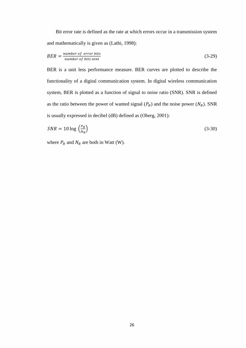
Figure 4.1 The additive white gaussian noise channel
As seen in figure 4.1, is a transmitted signal, is additive white gaussian
noise and signal output ( ) is given by (Proakis, 2000):
(4-1)
4.2 Fading Channel
In any wireless communication system there could be more than one path over
which the signal can travel between the transmitter and receiver antennas. The
presence of multiple paths is due to atmospheric scattering and refraction, or
reflections from buildings and other objects (Jeruchim, 2002).
The transmitted signal follows many different paths before arriving at the
receiving antenna, and it is the aggregate of these paths that constitutes the multipath
radio propagation channel. These waves called multipath waves, combined at the
receiver antenna to give resultant signal. The resulting signal strength will undergo
fluctuations that results in a fade (Jeruchim, 2002; Rappaport, 1996).
Small scale fading or simply fading is caused by interference between two or
more versions of the transmitted signal which arrive at the receiver at slightly
different times due to multipath radio propagation channel (Rappaport, 1996).
𝑛 𝑡
𝑠 𝑡
𝑟 𝑡 channel

29
For mobile radio applications, the channel is time-varying because the motion
between the transmitter and receiver results in propagation path changes. The time
variation of the channel ( in equation (4-3)) is characterised by the Doppler
frequency (Doppler shift) which is given by (Jeruchim, 2002):
(4-2)
Where, = Doppler shift (Hz), = velocity (m/sec), = carrier frequency (Hz) and
= light velocity (m/sec). Time varying wireless channel (fading channel), is
represented by the following equation (Jeruchim, 2002):
∑ (4-3)
where, and are path gains and path delays respectively of
multipath component at time .
For an input signal , the output of fading channel ( ) is given by (Proakis,
2000):
(4-2)
Where, is fading channel and is convolution operator.
Time dispersion ( in equation (4-3)) due to multipath causes the transmitted
signal to undergo either flat or frequency selective fading (Rappaport, 1996).
4.2.1 Flat fading
If the bandwidth of fading channel is greater than the bandwidth of the
transmitted signal, then the received signal will undergo flat fading. The
characteristics of a flat fading channel are illustrated in figure 4.2. Fading channel,
time and frequency domains of a flat fading channel are presented in figure 4.2(a),
4.2(b) and 4.2(c) respectively (Rappaport, 1996; Tse, 2005).

30
In a flat fading channel, the reciprocal bandwidth of the transmitted signal is
much larger than time delay spread of the channel (time between the first and the last
arriving of multipath components), and can be approximated as having no
excess delay (single delta function with as seen in figure 4.2(b) (Rappaport,
1996). Excess delay is the delay of n-th multipath component as compared to the
first arriving component. As shown in figure 4.2(c), the spectrum of the transmitted
signal is preserved at the output of flat fading channel.
(a) Fading channel
(b) Time domain of flat fading channel
(c) Frequency domain of flat fading channel
Figure 4.2 Flat fading channel characteristics
𝑡 𝜏
𝑠 𝑡 𝑟 𝑡
𝑠 𝑡 𝑡 𝜏 𝑟 𝑡
0 𝑇𝑠 0 𝜏 0 𝑇𝑠 𝜏
𝑡 𝑡 𝑡
𝜏 ≪ 𝑇𝑠
𝑆 𝑓
𝑓 𝑓
𝑓𝑐 𝑓𝑐
𝐻 𝑓
𝑅 𝑓
𝑓
𝑓𝑐

31
(a) Fading channel
(b) Time domain of frequency selective fading channel
(c) Frequency domain of frequency selective fading channel
Figure 4.3 Frequency selective fading channel characteristics
4.2.2 Frequency selective fading
If the bandwidth of fading channel is smaller than the bandwidth of the
transmitted signal, then the channel creates frequency selective fading on the
received signal. Characteristics of a frequency selective fading channel is illustrated
in figure 4.3 (Rappaport, 1996; Tse, 2005). Figure 4.3(a), 4.3(b), and 4.3(c) present
fading channel, time and frequency domains of a frequency selective fading channel.
As shown in figure 4.3(b), frequency selective fading channel has a multipath
delay spread which is greater than the reciprocal bandwidth of the transmitted signal.
𝑡 𝜏
𝑠 𝑡 𝑟 𝑡
𝑠 𝑡 𝑡 𝜏 𝑟 𝑡
0 𝑇𝑠 0 𝜏 0 𝑇𝑠 𝜏
𝑡 𝑡 𝑡
𝑇𝑠
𝑆 𝑓
𝑓 𝑓
𝑓𝑐 𝑓𝑐
𝐻 𝑓 𝑅 𝑓
𝑓
𝑓𝑐

32
When this occurs, the received signal includes multiple versions of the transmitted
signal which are attenuated and delayed in time, and hence the received signal is
distorted. Frequency selective fading is due to time dispersion of the transmitted
symbols within the channel. Thus, the channel induces intersymbol interference
(ISI). Viewed in frequency domain, certain frequency components in the received
signal spectrum have greater gains than others as presented in figure 4.3(c).

33
Chapter 5
DESIGN, IMPLEMENTATION AND ANALYSIS OF FIXED SPREADING
FACTOR HYBRID ORTHOGONAL VERY LARGE SET CODE SEQUENCE
Fixed spreading factor (fixed length) orthogonal Gold code sequence, orthogonal
m-sequence and orthogonal small set Kasami code sequence have been designed
from their non-orthogonal counter parts.
The method used by Donelan and O‟Farrell in 1999, for generating orthogonal
m-sequence has been adapted to the design of fixed spreading factor hybrid
orthogonal very large set (HOVLS) code sequence in this research work. My
research work applies this principle to two different types of spreading code
sequences namely large set Kasami code sequence and m-sequence, instead of using
two m-sequences (thus the name hybrid).
The proposed HOVLS code sequence is implemented in a synchronous CDMA
system, via simulation using Simulink/Matlab programming. The ACF, CCF, and
BER performance of the proposed HOVLS code sequence is evaluated and compared
to those of fixed spreading factor (fixed length) orthogonal Gold code sequence and
orthogonal m-sequence.
5.1 Design of HOVLS Code Sequence
The method used by Donelan and O‟Farrell, 1999 in generating orthogonal m-
sequence has been adapted to design the proposed HOVLS code sequence in this
research work.
Let large set Kasami code sequence and m-sequence, each of length (
for ) and generated using the same generator polynomial, be

34
represented by and respectively. These two code sequences can be
represented as:
(5-1)
(5-2)
Where denotes shift parameter; and
represent cyclic shift of large set Kasami code sequence and m-sequence
respectively.
and in equation (5-1) and (5-2) are binary digits. By replacing bit 0 by
1 and bit 1 by -1, hybrid code sequences are obtained by multiplying the large set
Kasami code sequence with all resulting m-sequence shifted by one chip. This is
expressed mathematically as below:
{
} {
(5-3)
where represents a cyclic shift of by j chips. As can be seen in
equation (5-3), for is the original large set Kasami code sequence.
The following steps describe the procedure to convert the hybrid code sequences
resulting from equation (5-3) to be a set of orthogonal code sequences (Donelan and
O‟Farrell, 1999):
Step 1: replace the first column (the first chips) by „1s‟.
Step 2: if the first chips were already all „1s‟ and therefore have not been altered by
step 1 then append „-1s‟ at the end of the code sequences (column).
Step 3: if the first chips were all „-1s‟and therefore have been altered by step 1 then
append „1s‟ at the end of the code sequences.
Step 4: repeat step 1 to 3 for all the code sequences represented in equation (5-3).

35
These steps in obtaining the proposed orthogonal code sequence can be
mathematically represented as below:
{ } ( { }
) (5-4)
where { }
is the resulting {
}
matrix with the first chip (column) (
)
removed.
The set of code sequence { }
is a set of code sequences of
matrix whose rows are orthogonal to each other.
Each value of „a‟ in equation (5-1) and (5-2), by the process explained above i.e.
applying equation (5-3) and (5-4), generates one set of orthogonal code sequence.
Therefore, one set of orthogonal code sequence will be generated for each value of
„a‟ using this process. As a result, there will be N different sets of orthogonal code
sequences. Each set contains code sequences (rows) of length chips
(columns). No two rows either in the same set or across the sets have the same code
sequence. Therefore, total number of different code sequences that can be generated
using this process is given by:
(5-5)
Referring to large set Kasami code sequence for , smallest value of
n equals to 6 and hence . Therefore, 63 different sets of orthogonal
code sequences can be generated where each set contains 64 code sequences of
length 64 chips. Hence, total number of different code sequences is
code sequences. These numbers (63 different sets of orthogonal code
sequences and 4032 number of different code sequences) for 64 chip length are the
same as the result that has been demonstrated by Donelan and O‟Farrell, 1999.
36
5.1.1 A Novel method to generate very large set of orthogonal code sequence
If this hybrid method as presented by equation (5-3) is applied to the large set
Kasami code sequences shown in expression (3-12) and m-sequence, a very large set
of orthogonal code sequence can be generated. The derivation of the different
components of the code sequence design is given below:
a. The first component
By substituting „0‟ for „a‟ in equation (5-3), a set of hybrid code sequence
generated as shown below:
{
} {
where is an m-sequence for .
Applying equation (5-4) to this set of hybrid code sequence, one set of
orthogonal code sequence is generated:
{ } ( { }
)
where { }
has code sequences (rows) of length chips
(columns).
By substituting „1‟ for „a‟ in equation (5-3), another set of hybrid code sequence
is generated and given by:
{
} {
where is an m-sequence for .
Applying equation (5-4) as above, another set of orthogonal code sequence is
generated:
{ } ( { }
)

37
where { } has code sequences (rows) of length chips (columns).
Using the same process as above, for all values of a, sets of orthogonal code
sequences, each of code sequences of length chips can be obtained.
In this case, sets of orthogonal sequences are generated from the original and the
shifted versions of an m-sequence, . Since an m-sequence is multiplied by a
cyclic shifted version of the same sequence, identical sets of orthogonal code
sequences are generated. Therefore the number of orthogonal code sequence sets
with a unique set of members in the sequences is 1.
b. The second component
For a = 0, equations (5-1) and (5-2) are given by:
and the set of hybrid code sequences shown in equation (5-3) is given by:
{
} {
Applying equation (5-4) to this set of hybrid code sequences, one set of
orthogonal code sequences is generated:
{ } ( { }
)
where { }
has code sequences (rows) of length chips
(columns).
Similarly, for a = 1, equations (5-1) and (5-2) are given by:
and the corresponding set of hybrid code sequences referring to equation (5-3) is
given by:

38
{
} {
Applying equation (5-4), another set of orthogonal code sequences is generated:
{ } ( { }
)
Using the same process as above, for all values of a, there exists sets of orthogonal
code sequences, each of code sequences of length chips.
As can be seen from this process, sets of orthogonal code sequences are
generated from and code sequences. Since and are different code
sequences, combination of m-sequence and the second component of expression (3-
12) of large set Kasami code sequence generate different sets of orthogonal code
sequences.
c. The third component
Let us take the first sequence of the third component of expression (3-12). This
component is given by:
XOR operator is the same as multiply operation if bit 0 in a code sequence is
replaced by 1 and bit 1 by -1 (Donelan and O‟Farrell, 1999). Following this
operation the equations (5-1) and (5-2) are given as below:
and the corresponding set of hybrid code sequences shown in equation (5-3) is given
by:
{
} {

39
As can be seen in this equation, sets of hybrid code sequences are constructed
from and code sequences. Using the same process as above, since and
represent different code sequences, combination of m-sequence and the third
component of the expression (3-12) for large set Kasami code sequence generate
different sets of orthogonal code sequences.
d. The fourth component
Let us now consider the first code sequence of the fourth component of
expression (3-12). This component is given by:
and therefore, the corresponding representation of equations (5-1) and (5-2) is given
below:
and the corresponding set of hybrid code sequences shown in equation (5-3) is given
by:
{
} {
As can be seen in this equation, sets of hybrid code sequences are constructed
from and code sequences. Using the same process as above, N sets of
orthogonal code sequences can be generated.
However, since the code sequence must be first repeated – times
before performing the XOR operation as explained in section 3.2.3, there are
– identical sets of orthogonal code sequences. Therefore, combination of

40
m-sequence and the fourth component of equation (3-12) generates –
different sets of orthogonal code sequences.
e. The fifth component
Let us consider the first code sequence of the fifth component of expression (3-
12). This component is given by:
and hence, equations (5-1) and (5-2) are given as follows:
and the resulting set of hybrid code sequences shown in equation (5-3) is given by:
{
} {
As can be seen in this equation, sets of hybrid code sequences are constructed
from , and code sequences.
Using the same process as above, since , , and are different code
sequences, combination of m-sequence and the fifth component of expression (3-12)
of large set Kasami code sequence generate different sets of orthogonal code
sequences.
f. The sixth component
Let us consider the first code sequence of the sixth component of expression (3-
12). This component is given by:
and therefore, equivalent of equations (5-1) and (5-2) is given as follows:

41
and the corresponding set of hybrid code sequences shown in equation (5-3) is given
by:
{
} {
As can be seen in this equation, sets of hybrid code sequences are constructed
from , and code sequences.
Using the same process as above, since , , and are different
sequences, combination of m-sequence and the fifth component of expression (3-12)
of large set Kasami sequence generate different sets of orthogonal code sequences.
The orthogonal code sequence sets resulting from the fifth component are same
as that from the sixth component, as they were generated by this hybrid method using
the same code sequences. Also, similar sets of orthogonal code sequences will result
from the second and third components, for the reason stated above. Hence, to obtain
dissimilar sets of orthogonal code sequences, the fifth or the sixth component and the
second or the third component must be eliminated. Therefore, total number of
orthogonal code sequence sets ( ) can be obtained by adding sets obtained from the
first component to the sixth component by selecting only one set from the similar
sets as mentioned above:
(
– ) (5-6)
And the total number of different code sequences ( ) that can be generated is
obtained by multiplying the total number of orthogonal code sequence sets ( ) by
the number of members in a set :

42
(
– ) (5-7)
5.2 Implementation and Analysis of The Proposed HOVLS code sequence
The proposed HOVLS code sequence is implemented in a synchronous CDMA
system, via simulation using Simulink/Matlab programming to analysis the
performance metrics such as family size or capacity, autocorrelation function, cross-
correlation function, and bit error rate (BER) performance. BER performance of the
proposed HOVLS code sequence is analysed under two different channel conditions
namely Rayleigh flat and frequency selective fading channels. The performance of
the proposed HOVLS code sequence is compared to that of orthogonal Gold code
sequence and orthogonal m-sequence.
5.2.1 Simulation of the proposed HOVLS code sequence
A set of assumptions have been made for the simulation of the synchronous
CDMA system, which are given in section 5.2.1.2. The block diagram and the
rationale behind the blocks used to simulate the synchronous CDMA system are
given in section 5.2.1.1. Number of Monte Carlo simulations used for this system is
five times.
5.2.1.1 Block diagram of the synchronous CDMA system
The block diagram of the simulation model used is shown in figure 5.1. This
simulation is performed under Rayleigh flat and frequency selective fading channel
conditions.
At the input of the system, randomly generated binary digit (bit) information is
modulated using DBPSK modulator to produce DBPSK symbols. The CDMA

43
system assigns each user different spreading code sequence from a set of code
sequences that are from the same family to spread the DBPSK symbols. The spread
spectrum signal is then radiated into the channel. At the AWGN channel output, the
received signal is de-spread using a correlation receiver. This process will reject the
interfering signals and pass the desired signal to DBPSK demodulator. The desired
signal is then demodulated to obtain the desired bit information.
Figure 5.1 Block diagram for the simulation of synchronous CDMA system
5.2.1.2 Assumptions for the simulation of the synchronous CDMA system
Based on the block diagram of the simulation model shown in figure 5.1, the
assumptions for the simulations are as follows:
The input considered is binary bit sequence with Bernoulli distribution with
same probability between bit 0 and 1.
The total number of bits for the entire simulation is 300 Kbits.
Spreading
Code
DBPSK
Modulator
Binary Digits
Information
Additive White Gaussian
Noise Channel
∑
De-spreading
Received Signal DBPSK
Demodulator
Received
Binary Digits
Information
Desired user
Binary Digits
Information
Spreading
Code
Interfering user
DBPSK
Modulator
Multipath
Rayleigh
Channel
44
Sampling time = 0.001 second.
Modulation is DBPSK.
The number of users is 64.
The average power transmitted by each user‟s signal at the base station is 1
Watt.
Spreading code sequence lengths is 64 chips.
The receiver is a correlation receiver.
The desired signal and MAI signals are chip synchronized at the receiver.
There is no interference from other cells.
Rayleigh flat fading channel is modeled by one path with a path gain equal to 0
dB.
Rayleigh frequency selective fading channel is modeled with four path time
delays (0 , 1 chip duration, 2 chips duration, 3 chips duration) and four path
gains (0 dB, -3 dB, -6 dB -9 dB). One chip duration
6
second.
To represent mobile radio channel, it is assumed a desired user (a pedestrian
user) moving with speed of 5 km/hour. Since carrier frequency used in CDMA
systems is 2.11 GHz (Rao and Dianat, 2005), based on equation (4-2), Doppler
shift is 10 Hz.
5.2.2 Simulation results and discussion
In the following section, the performance metrics of the proposed HOVLS code
sequence simulated using Simulink/Matlab programming is compared to those of
orthogonal Gold code sequence and orthogonal m-sequence.

45
5.2.2.1 Capacity and peak cross-correlation value of the proposed HOVLS code
sequence
As shown in table 5.1, the proposed code sequence has the largest code sequence
set. These sets can be used simultaneously if the peak cross-correlation value
between the code sequences (from different groups) is less than half of the code
sequence length (Donelan and O‟Farrel, 1999). Since the peak cross-correlation
value of the proposed code sequence of length 64 chips is 16, which is one quarter of
64, 134 groups of the proposed code sequence can be used simultaneously. This
means, this code sequence set could support 134 different cells in a synchronous
CDMA system.
Table 5.1 Capacity and peak cross-correlation value of the proposed and selected
orthogonal code sequences
Orthogonal code sequence
Length of
code
sequence
(chips)
Number
of sets
Capacity
of code
sequence
(users)
Peak cross-
correlation
value
The proposed HOVLS code 64 134 8676 16
Orthogonal Gold 64 63 4032 16
Orthogonal m-sequence 64 63 4032 16
5.2.2.2 Autocorrelation function of the proposed HOVLS code sequence
Autocorrelation function of the proposed HOVLS code sequence, orthogonal
Gold code sequence and orthogonal m-sequence for 64 chip lengths are presented in
figures 5.2 to 5.4 respectively. As seen in the figures 5.2 to 5.4, at zero time shifts the
orthogonal code sequences have maximum autocorrelation values (the same as the
length of the code sequences) since the values were obtained from correlation
between the code sequence with a copy of itself that has the same chips structure as
the original one. Whereas, at non-zero time shifts, the autocorrelation values are

46
much lower than that of zero time shift due to different chips structure between the
two code sequences. The autocorrelation value at zero time shift represents desired
user‟s signal strength while that at non-zero time shifts represent inter-symbol
interference (ISI) signal strengths.
Based on these autocorrelation functions, merit factor (MF) of the proposed
HOVLS code sequence, orthogonal Gold code sequence and orthogonal m-sequence
is tabulated in table 5.2.
Since MFs of these orthogonal code sequences are similar, the proposed HOVLS
code sequence has autocorrelation function values comparable to those of orthogonal
Gold code sequence and orthogonal m-sequence.
Table 5.2 Merit factor of the proposed HOVLS code sequence
Orthogonal code sequence Length of code sequence
(chips) MF
The proposed HOVLS code 64 0.68
Orthogonal Gold 64 0.82
Orthogonal m-sequence 64 0.59

47
Figure 5.2 ACF of the proposed HOVLS code sequence
Figure 5.3 ACF of orthogonal Gold code sequence
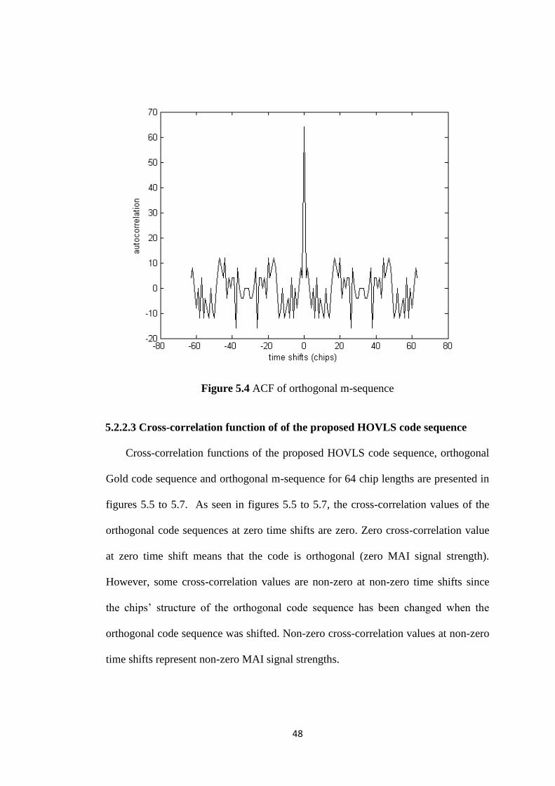
48
Figure 5.4 ACF of orthogonal m-sequence
5.2.2.3 Cross-correlation function of of the proposed HOVLS code sequence
Cross-correlation functions of the proposed HOVLS code sequence, orthogonal
Gold code sequence and orthogonal m-sequence for 64 chip lengths are presented in
figures 5.5 to 5.7. As seen in figures 5.5 to 5.7, the cross-correlation values of the
orthogonal code sequences at zero time shifts are zero. Zero cross-correlation value
at zero time shift means that the code is orthogonal (zero MAI signal strength).
However, some cross-correlation values are non-zero at non-zero time shifts since
the chips‟ structure of the orthogonal code sequence has been changed when the
orthogonal code sequence was shifted. Non-zero cross-correlation values at non-zero
time shifts represent non-zero MAI signal strengths.

49
Based on these cross-correlation functions, correlation margin (CM) of the
proposed HOVLS code sequence, orthogonal Gold code sequence and orthogonal m-
sequence for 64 chip lengths is tabulated in table 5.3.
As seen in table 5.3, the proposed HOVLS code sequence has CM comparable to
those of orthogonal Gold code sequence and orthogonal m-sequence. Therefore, in
terms of CM, the proposed HOVLS code sequence has comparable CCF to those of
orthogonal Gold code sequence and orthogonal m-sequence.
Table 5.3 CM of the proposed HOVLS code sequence
Spreading code sequence Length of code sequence
(chips) CM(dB)
The proposed HOVLS
code 64 -13.01
Orthogonal Gold 64 -13.01
Orthogonal m-sequence 64 -12.04

50
Figure 5.5 CCF of the proposed HOVLS code sequence
Figure 5.6 CCF of orthogonal Gold code sequence

51
Figure 5.7 CCF of orthogonal m-sequence
5.2.2.4 BER performance of the proposed HOVLS code sequence under
Rayleigh flat fading channel condition
In any digital communication system, BER values decrease for increasing SNR
value, since increasing SNR value means the desired signal power becomes higher
than the noise power. When the desired signal power increases, the number of bits
corrupted by the noise becomes smaller, therefore BER values decrease (Proakis,
2000). Evaluation of the BER performance of the proposed HOVLS code sequence
demonstrates that the BER values decrease as SNR value increases, as seen in
subsections 5.2.24, 5.2.2.5, 6.2.2.4, 6.2.2.5, 6.2.2.6 and 6.2.2.7.
As can be seen from figure 5.8, the proposed HOVLS code sequence has similar
BER performance to those of orthogonal Gold code sequence and orthogonal m-
sequence in a synchronous CDMA system under Rayleigh flat fading channel. The
reasons for this performance behaviour are discussed in the following paragraphs.

52
In flat fading channel condition there is no excess delay, and hence when de-
spreading the received signal, both the autocorrelation (ACF) and cross-correlation
functions (CCF) of the orthogonal spreading code sequences will be at zero time shift
as shown in figures 5.2 to 5.7. Therefore, there is no Inter-symbol interference (ISI)
and multiple access interference (MAI) at the receiver, and hence BER value is
constant for increasing number of users. However, as seen in figure 5.8, BER values
of the orthogonal code sequences decrease only for increasing SNR value, therefore
the orthogonal code sequences are operating under noise limited condition.
Since these code sequences are under noise limited condition (MAI does not
exist), and have similar desired user‟s signal strength represented by ACF at zero
time shift due to the absence of ISI, therefore these orthogonal code sequences have
similar BER performance.
Figure 5.8 BER versus SNR of the orthogonal code sequences under Rayleigh flat
fading channel

53
5.2.2.5 BER performance of the proposed HOVLS code sequence under
Rayleigh frequency selective fading channel condition
As seen from figure 5.9, the proposed HOVLS code sequence has BER
performance similar to that of orthogonal Gold code sequence and orthogonal m-
sequence in a synchronous CDMA system under Rayleigh frequency selective fading
channel conditions. The reason behind this performance is discussed below.
In frequency selective fading channel, the received signal includes multiple
versions of the transmitted signal which are attenuated and delayed in time.
Therefore, ISI and multiple access interference (MAI) occur when de-spreading the
received signal, due to the non-zero values of ACF and CCF of the orthogonal code
sequences at non-zero time shifts. This is presented in figures 5.2 to 5.7. Under this
condition, the desired user‟s signal is distorted and BER value increases with
increasing number of users as seen in figure 5.10. However, BER values of the
orthogonal code sequences as shown in figure 5.9 decrease with increasing SNR
value, therefore these orthogonal code sequences are under both noise and multiple
access interference (MAI) limited conditions. Since these orthogonal code sequences
are under similar conditions and have comparable ACF (similar BER value for one
user) and CCF (similar BER value for increasing number of users), their BER
performance is similar as shown in figure 5.9.
Comparison between BER performances of the orthogonal code sequences under
flat fading channel condition to that of under frequency selective fading channel is
shown in figures 5.8 and 5.9 respectively.
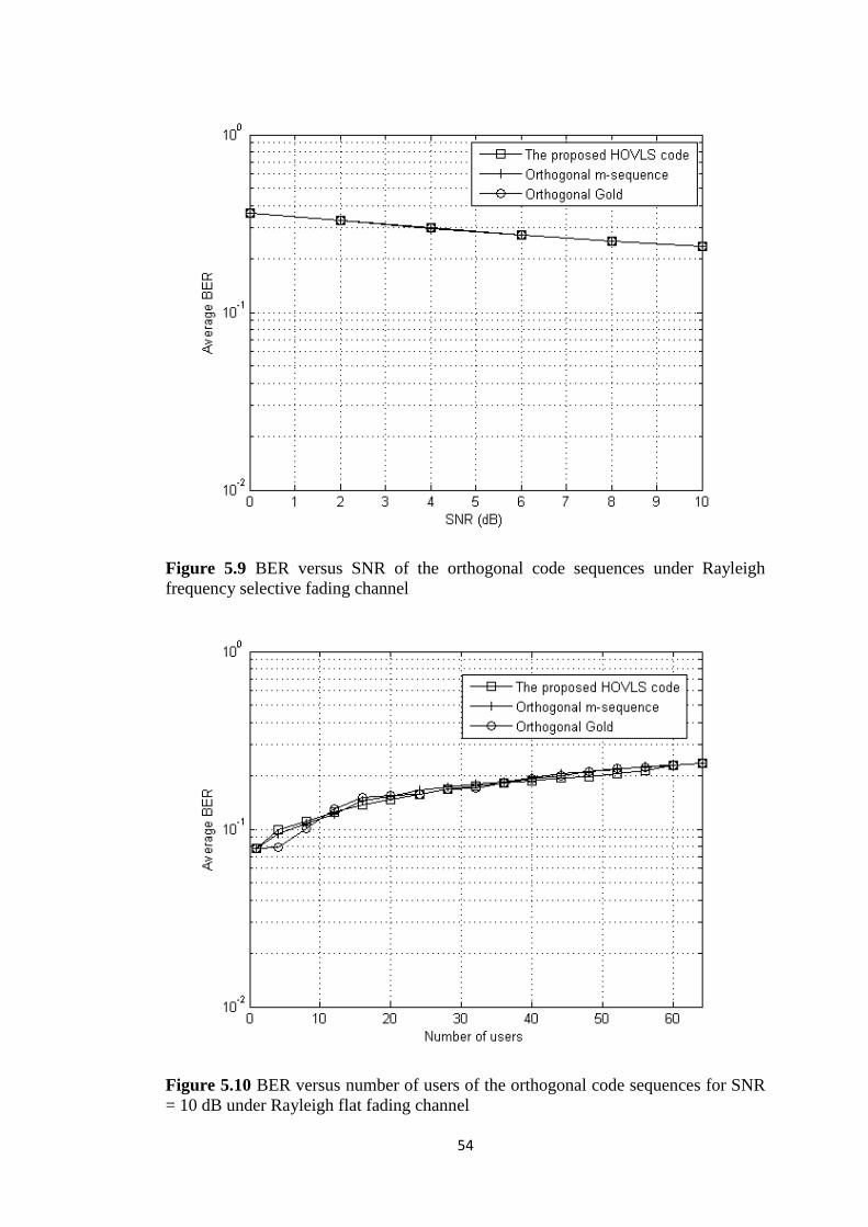
54
Figure 5.9 BER versus SNR of the orthogonal code sequences under Rayleigh
frequency selective fading channel
Figure 5.10 BER versus number of users of the orthogonal code sequences for SNR
= 10 dB under Rayleigh flat fading channel

55
BER performances of the orthogonal code sequences under frequency selective
fading channel are worse than that of under flat fading channel, due to MAI and ISI
under frequency selective fading channel conditions. However, there is no ISI and
MAI when implementing orthogonal code sequences in synchronous CDMA system
under flat fading channel condition.
The proposed HOVLS code sequence has similar BER performance to those of
orthogonal code sequence and orthogonal m-sequence under Rayleigh frequency
selective fading channel. This means that the proposed HOVLS code sequence has
levels of effect from MAI similar to that of the orthogonal Gold code sequence and
orthogonal m-sequence in CDMA systems. However, the proposed HOVLS code
sequence fairs much better than those existing codes in terms of its capacity. This
means, the proposed HOVLS code sequence can accommodate very large number of
users, which is more than twice than that of orthogonal code sequence and
orthogonal m-sequence.

56
Chapter 6
DESIGN, IMPLEMENTATION AND ANALYSIS OF VARIABLE
SPREADING FACTOR HYBRID ORTHOGONAL VERY LARGE SET
CODE SEQUENCE
Nowadays, cellular phone operators are in a scramble to meet huge demands
from their customers for transmitting a blend of data types such as audio, data, image
and video transfer at high data rates. This is the target for mobile phone operators in
order to improve capabilities of multimedia communications. One way to flexibly
provide data services of different rates from low to very high bit rates is to assign
orthogonal code sequences with different lengths in the forward link to each user
according to the data rate requested. This will ensure constant chip rate after
spreading at variable data rate. An orthogonal code sequence used for different bit
rates is called an orthogonal variable spreading factor (OVSF) code sequence
(Adachi, et.al., 1997; Feng, et.al., 2007; Wang, et.al., 2008).
Since an orthogonal code sequence must have the capability to support variable
data rate, a novel design was developed to adapt the fixed length HOVLS code
sequence for variable data rate.
The BER performance of the proposed OVSF HOVLS code sequence is
evaluated and compared to OVSF Gold code sequence and OVSF m-sequence in
synchronous CDMA system, using Rayleigh flat and frequency selective fading
channels. Besides ACF and CCF of the OVSF code sequences are also evaluated.
This evaluation is performed via simulation using Simulink/Matlab programming.

57
6.1 Design of the proposed OVSF HOVLS code sequence
In a CDMA system providing services of differing bit rates, consider that each
bit of the lowest bit rate service (Rmin) is spread by a code sequence length
( where is a positive integer number). A code sequence with a bit rate twice
that of the lowest bit rate (2Rmin) code sequence will have half the code sequence
length of the lowest bit rate ( -
) code sequence, since the bit duration for
2Rmin rate is half the duration of a bit with minimum rate (Dinan and Jabbari, 1998;
Karakayali et. al., 2006; Amico et. al., 2002):
(1)
where is bit duration. In such a system, OVSF code sequences such as the
proposed OVSF HOVLS code sequence could accommodate applications ranging
across different bit rate values such as audio, data, image and video represented by
different spreading factor (SF). However, for simplicity, only two different bit rates
were considered. In this case two different SFs (128 and 256) are used to evaluate the
performance of the proposed OVSF HOVLS code sequence.
Adapting the method demonstrated by (Adachi et. al., 1997), the code tree for
the OVSF HOVLS code sequence has been designed as shown in figure 6.1. The
minimum spreading factor for the proposed OVSF HOVLS code sequence is 64,
since the minimum length of the proposed fixed length HOVLS code sequence is 64.
Therefore, the different spreading factors that can be generated using the code tree
are 64, 128, 512, etc., as shown in figure 6.1. K64 denotes a set of the proposed OVSF
HOVLS code sequences having 64 members, each of length 64, while 64 represents
binary complement of the K64 code sequence set.
The code tree shown in figure 6.1 starts from the root of the code tree i.e.
the 64 HOVLS code sequence of length 64 chips (the proposed fixed length

58
HOVLS code sequence) as a mother with a spreading factor of 64. This mother has
two child code sequences denoted by 64 64 and 64 64 each having a spreading
factor of 128. Each of these child code sequences will be a mother in turn for two
child code sequences with a spreading factor of 256 each. The same process is
performed to obtain higher spreading factor code sequences.
Figure 6.1 Code sequence tree for generation of OVSF HOVLS code sequences
The proposed OVSF HOVLS code sequences belonging to the same layer (i.e.
same SF in figure 6.1) of the code tree form a set of orthogonal code sequences with
zero cross-correlation values. Also, the code sequences belonging to different layers
(i.e. different SFs in figure 6.1) are orthogonal, provided these code sequences do
not have mother-child relationship. In fact, a code sequence in the code tree can be
used by a mobile station iff (if and only if) no other code sequence on the path from

59
the specific code sequence to the root of the code tree or in the code sub-tree below
the specific code sequence is used by other mobile stations.
As presented in figure 6.1, each layer contains groups of code sequences. Each
group of code sequences corresponds to a branch (a line) in the code tree having a
member of 64 code sequences. Therefore, layer 1 (SF = 64) contains one group of
code sequences, layer 2 (SF = 128) contains two groups of code sequences where
group 1 corresponds to first branch (first line) and group 2 corresponds to second
branch (second line) in that layer, and more groups for higher spreading factor (if a
layer has SF value twice that of another layer, then the layer with higher SF will have
twice the number of groups having lower SF).
Orthogonal Gold code sequence and orthogonal m-sequence can also be made to
support multi rate data transmissions by adapting the method demonstrated by
Adachi et. al., 1997. Since the minimum code sequence length of the orthogonal
Gold code sequence and orthogonal m-sequence is 8, various spreading factors that
can be generated using the code tree are 8, 16, 32, 64, etc. The detailed calculation is
presented in appendices A and B.
6.2 Implementation and Analysis of The Proposed OVSF HOVLS Code
Sequence
The proposed OVSF HOVLS code sequence is implemented in a synchronous
CDMA system to analysis its BER performance under different channel conditions
namely Rayleigh flat and frequency selective fading channels, via simulation using
Simulink/Matlab programming. ACF and CCF of the proposed OVSF HOVLS code
sequence are also analysed, and compared to that of the existing OVSF code
sequences namely OVSF Gold code sequence and OVSF m-sequence.

60
6.2.1 Simulation of the proposed OVSF HOVLS code sequence
To simulate the proposed OVSF HOVLS code sequence in a synchronous
CDMA system, two kinds of scenarios have been adopted, which are given in section
6.2.1.1, and the assumptions for the simulation are given in section 6.2.1.2. The
block diagram and the rationale behind the blocks used to simulate the synchronous
CDMA system have been discussed in section 5.2.1.1. Number of Monte Carlo
simulations used for this system is five times.
6.2.1.1 Scenario for simulation of the proposed OVSF HOVLS code sequence
Though the proposed OVSF HOVLS code sequence is able to accommodate any
number of different bit rates, for simplicity, only two kinds of users namely user 2R
and R were considered in this scenario. The total number of users in this simulation
is 64. User 2R transmits information at twice the bit rate than that of user R.
a. Scenario for user 2R
In order to analysis the BER performance of the proposed OVSF HOVLS code
sequence, the system was populated with a total of 64 users of which 16 were with
2R bit rate in this simulation. The BER values were measured for an increasing
number of users, first by increasing the number of users with 2R bit rate from 1 to 16
and then by increasing the number of users with R bit rate until the total number of
users in the system were 64. The OVSF Gold code sequence and OVSF m-sequence
do not have zero MAI due to non-zero CCF for scenarios with less than 8 users. So,
in order to make a fair comparison of the codes sequences, a scenario with more than
8 users has to be considered so that the OVSF Gold code sequence and OVSF m-
sequence will have zero MAI. Therefore, 16 user 2Rs were chosen to evaluate the
BER values of the proposed OVSF code sequence when OVSF Gold code sequence
and OVSF m-sequence have zero MAI. The BER performance was measured to see

61
the effect when the desired user is interfered by MAI coming from other users with
both 2R and R data rates.
b. Scenario for user R
The scenario for user R is the same as that for user 2R described above, with the
users R and 2R interchanged.
6.2.1.2 Simulation assumptions for the proposed OVSF HOVLS code sequence
of synchronous CDMA system
The assumptions for the simulations are as follows:
The input considered is Bernoulli distribution with same probability between
bit 0 and 1.
Sampling time = 0.001 sec.
The total number of bits for the entire simulation is 300 Kbits for user R and
600 Kbits for user 2R, since user 2R has twice bit rate than user R. In this case,
there are 2 bits per frame for user 2R and 1 bit per frame for user R.
For the proposed OVSF HOVLS code sequence, user 2R is allocated code
sequences of layer 2 of group 1 and user R is allocated code sequences of layer
3 of group 3 so that there is no mother-child relationship.
For OVSF Gold code sequence and OVSF m-sequence, user 2R is allocated
code sequences of layer 5 of group 1 to 8 and user R is allocated code
sequences of layer 6 of group 17 to 32 so that there is no mother-child
relationship.
Modulation is DBPSK.
The number of users is 64.
The average power transmitted by each user‟s signal at the base station is 1
Watt.

62
The receiver is a correlation receiver.
The desired signal and MAI signals are chip synchronized at the receiver.
Each signal is assumed to arrive at the receiver with equal average power.
There is no interference from other cells.
Rayleigh flat fading channel is modeled by one path with a path gain equal to 0
dB and a Doppler shift of 10 Hz.
Rayleigh frequency selective fading channel is modeled with four path time
delays (0 , 1 chip duration, 2 chips duration, 3 chips duration) and four path
gains (0 dB, -3 dB, -6 dB -9 dB), and with 10 Hz Doppler shift. One chip
duration =
8 second
As user 2R has twice the bit rate of user R, from the code tree shown in figure
6.1, if SF = 128 is selected for user 2R then SF = 256 will have to be selected for
user R. However, code sequences having mother – child relationship between the
code sequence sets with SF = 128 and code sequence sets with SF = 256 must not be
selected for the group, as these code sequences are non-orthogonal. As seen in the
code tree in figure 6.1, the code sequence with SF = 64 for user 2R and SF = 128
user R cannot be selected as all code sequences with SF = 64 and SF = 128 have
mother – child relationship.
Therefore, in this simulation the author used code sequences with SF = 128 of
group 1 (first line of SF = 128) in the code tree for user 2R and code sequences with
SF = 256 of group 3 (third line of SF = 256) for user R.
6.2.2 Simulation results and discussion
The performance of the proposed OVSF HOVLS code sequence is analysed in
terms of autocorrelation function (ACF), cross-correlation function (CCF), and BER

63
under Rayleigh flat and frequency selective fading channel conditions. These
parameters will be benchmarked against that of OVSF Gold code sequence and
OVSF m-sequence.
6.2.2.1 Autocorrelation function of the proposed OVSF HOVLS code sequence
ACF of the OVSF code sequence proposed by Adachi, et.al, 1997 at some zero
time shifts has similar autocorrelation values to that of non-zero time shift. The
proposed OVSF HOVLS code sequence, OVSF Gold code sequence and OVSF m-
sequence were all generated by adapting the method proposed by Adachi, et.al, 1997.
Therefore, they have autocorrelation values at some non-zero time shifts similar to
that of at zero time shift, as seen in figures 6.2 to 6.4 and figures 6.5 to 6.7.
As seen in figures 6.2 to 6.4 and figures 6.5 to 6.7, the proposed OVSF HOVLS
code sequence has comparable autocorrelation function to those of OVSF Gold code
sequence and OVSF m-sequence for 128 and 256 chips lengths respectively, since
each of these OVSF code sequences has similar merit factor (MF) as shown in table
1 which are less than 2 (Wieser and Hrudkay, 2002). That is the ratio of the
autocorrelation energy at zero time shift ( ) to the total energy of
autocorrelation at non zero time shifts ( ) for the OVSF code sequences is
similar.
Table 6.1 MF of the proposed OVSF HOVLS code sequence
OVSF code sequence MF for 128 chip lengths MF for 256 chip lengths
Orthogonal Gold 0.02 0.01
Orthogonal m-sequence 0.02 0.01
The proposed code 0.20 0.08

64
Figure 6.2 ACF of the proposed OVSF HOVLS code sequence for 128 chip lengths
Figure 6.3 ACF of OVSF Gold code sequence for 128 chip lengths

65
Figure 6.4 ACF of OVSF m-sequence for 128 chip lengths
Figure 6.5 ACF of the proposed OVSF HOVLS code sequence for 256 chip lengths
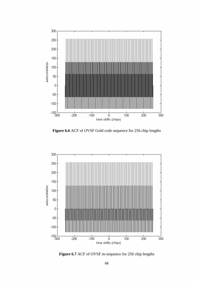
66
Figure 6.6 ACF of OVSF Gold code sequence for 256 chip lengths
Figure 6.7 ACF of OVSF m-sequence for 256 chip lengths

67
6.2.2.2 Cross-correlation function of the proposed OVSF HOVLS code sequence
in same groups in the code tree
Cross-correlation functions of the proposed OVSF HOVLS code sequence,
OVSF Gold code sequence and OVSF m-sequence from the same group in the code
tree are shown in figures 6.8 to 6.10 and figures 6.11 to 6.13 for 128 and 256 chips
length respectively. The proposed OVSF HOVLS code sequence, OVSF Gold code
sequence and OVSF m-sequence belonging to the same group in the code tree, at
zero time shifts have zero cross-correlation values, as they are orthogonal code
sequences. However, at some non-zero time shifts, cross-correlation values are not
zero, since chips structure has been changed by chips shifted at non-zero time shifts.
As presented in table 6.2, the proposed OVSF HOVLS code sequence has
slightly higher correlation margin (2.04 dB more tolerant for SF = 128 and 2.50 dB
for SF = 256 in multi users environment) than that of OVSF Gold code sequence and
OVSF m-sequence. Whereas CM of OVSF Gold code sequence is similar to that of
OVSF m-sequence. Therefore, in terms of CM, the proposed OVSF HOVLS code
sequence has slightly better CCF than that of OVSF Gold code sequence and OVSF
m-sequence, and CCF of OVSF Gold code sequence is comparable to that of OVSF
m-sequence. Cross-correlation functions of the proposed OVSF HOVLS code
sequence, OVSF Gold code sequence and OVSF m-sequence from the same group in
the code tree are shown in figures 6.8 to 6.10 and figures 6.11 to 6.13 for 128 and
256 chips length respectively.

68
Table 6.2 CM of the proposed OVSF HOVLS code sequence
Figure 6.8 CCF of the proposed OVSF HOVLS code sequence in the same groups in
the code tree for 128 chip lengths
OVSF code sequence CM for 128 chip lengths
(dB)
CM for 256 chip lengths
(dB)
Orthogonal Gold -18.06 -21.07
Orthogonal m-sequence -18.06 -21.07
The proposed code -16.02 -18.57

69
Figure 6.9 CCF of OVSF Gold code sequence in the same groups in the code tree for
128 chip lengths
Figure 6.10 CCF of OVSF m-sequence in the same groups in the code tree for 128
chip lengths
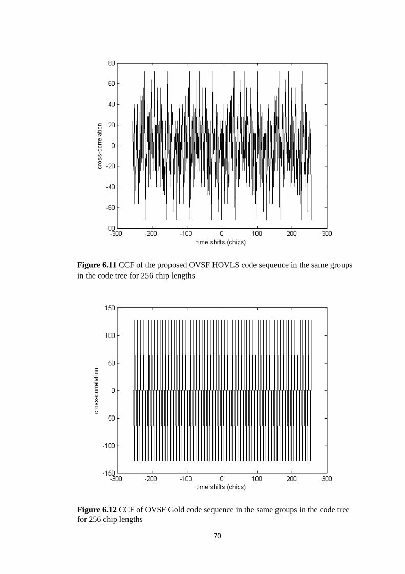
70
Figure 6.11 CCF of the proposed OVSF HOVLS code sequence in the same groups
in the code tree for 256 chip lengths
Figure 6.12 CCF of OVSF Gold code sequence in the same groups in the code tree
for 256 chip lengths

71
Figure 6.13 CCF of OVSF m-sequence in the same groups in the code tree for 256
chip lengths
6.2.2.3 Cross-correlation function of the proposed OVSF HOVLS code sequence
from different groups in the code tree
The OVSF code sequence proposed by Adachi, et.al, 1997 has zero CCF
between any two code sequences that are from different groups in the code tree.
Since the proposed OVSF HOVLS code sequence, OVSF Gold code sequence, and
OVSF m-sequence were generated by adapting the method proposed by Adachi,
et.al, 1997, CCFs between different groups in the code tree of the proposed OVSF
HOVLS code sequence, OVSF Gold code sequence, and OVSF m-sequence are
zeroes.
Cross-correlation function between a user 2R using code sequence of 128 chip
lengths and a user R using code sequence of 256 chip lengths has been derived by
repeating the code sequence of length 128 chips twice before correlating the code

72
sequences. In this case we correlate two code sequences of length 256 chips. Since
code sequences used by users 2R or R must not be of mother-child relationship,
correlation between a user 2R (128 chips length) and a user R (256 chips length)
means correlation between different groups of two code sequences of length 256.
6.2.2.4 BER performance of the proposed OVSF HOVLS code sequence under
Rayleigh flat fading channel
Figure 6.14 shows BER performance of the proposed OVSF HOVLS code
sequence, OVSF Gold code sequence and OVSF m-sequence under Rayleigh flat
fading channel condition. As can be clearly seen from figure 6.14, the proposed
OVSF HOVLS code sequence has similar BER performance to that of OVSF Gold
code sequence and OVSF m- sequence in synchronous CDMA system under
Rayleigh flat fading channel. The reasons for this performance behaviour are
discussed in the following paragraphs.
Since there is only one version of the transmitted signal arriving at the receiver
under flat fading channel condition, inter symbol interference (ISI) does not exist on
desired user‟s signal and there is no interfering signal from other users (no MAI).
Under this condition, the OVSF code sequences can maintain the orthogonality of the
code sequences; therefore BER value is constant for increasing number of users.
However, as seen in figure 6.14, BER value decreases for increasing SNR value,
therefore under flat fading channel condition the OVSF code sequences are noise
limited or the receiver has only to cope with the noise introduced by the channel.
Under Rayleigh flat fading channel condition, the proposed OVSF HOVLS code
sequence, OVSF Gold code sequence and OVSF m-sequence are under same
condition that is under noise limited condition (no MAI) and there is no ISI on the
desired received user‟s signal and hence have similar signal strength due to same

73
value on zero time shift on ACF. Therefore the proposed OVSF HOVLS code
sequence, OVSF Gold code sequence and OVSF m-sequence have similar BER
performance.
BER performance of the proposed OVSF HOVLS code sequence, OVSF Gold
code sequence and OVSF m-sequence are also similar for user R under Rayleigh flat
fading channel condition as seen in figure 6.15 for the same reason as discussed
above for user 2R.
So, BER performance of the OVSF code sequences under flat fading channel
condition does not depend on user with higher bit rate (2R) or user with lower bit
rate (user R)) in downlink CDMA systems. Therefore, BER performance of these
OVSF code sequences between user 2R and R under Rayleigh flat fading channel is
similar.

74
Figure 6.14 BER versus SNR of the OVSF code sequences under Rayleigh flat
fading channel for user 2R
Figure 6.15 BER versus SNR of the OVSF code sequences under Rayleigh flat
fading channel for user R

75
6.2.2.5 BER performance of the proposed OVSF HOVLS code sequence under
Rayleigh frequency selective fading channel for user 2R
As seen in figure 6.16, the proposed OVSF HOVLS code sequence has slightly
better BER performance than those of OVSF Gold code sequence and OVSF m-
sequence. Besides, BER performance of OVSF Gold code sequence is slightly better
than that of OVSF m-sequence. The reason is discussed in the following paragraphs.
Under frequency selective fading channel, received signal is multiple versions of
the transmitted signal which are attenuated and delayed in time. When de-spreading
the received signal, correlation between the first multipath component (not just
delayed and attenuated) and the desired user‟s code sequence is the desired signal.
Whereas, the correlation between the desired user‟s code sequence and other
multipath components (delayed and attenuated) are undesired signals that will
interfere with the desired signal. These correlation values are determined by ACF of
the code sequences where correlation value at zero time shift represents desired
user‟s signal strength while at non-zero time shifts represents undesired signals
strengths (ISI).
As shown in figures 6.2 to 6.4, the proposed OVSF HOVLS code sequence,
OVSF Gold code sequence and OVSF m-sequence have similar ACF for code
sequence of length 128 chips. Therefore, BER values of the proposed OVSF
HOVLS code sequence, OVSF Gold code sequence, and OVSF m-sequence for one
user 2R are similar to others, as seen in figure 6.17. However, when there is more
than one user in CDMA system, the desired user‟s signal is not only interfered by ISI
but also by interfering signals coming from others users. Interfering signal strengths
coming from other users are determined by cross-correlation values at non-zero time

76
shift in the CCF, since correlation values at non-zero time shifts in CCF for
orthogonal code sequences represent signal strengths from other users.
As seen in figures 6.8 to 6.10, CCF of the proposed OVSF HOVLS code
sequence is slightly better in terms of CM than that of OVSF Gold code sequence
and OVSF m-sequence for code sequence of length 128 chips. Therefore, the
proposed OVSF HOVLS code sequence has slightly lower BER values for increasing
number of users than those of OVSF Gold code sequence and OVSF m-sequence as
shown in figure 6.17, and hence BER performance of the proposed OVSF HOVLS
code sequence for user 2R that has 128 chip lengths is slightly better than those of
OVSF Gold code sequence and OVSF m-sequence.
Figure 6.16 BER versus SNR of the OVSF code sequences under Rayleigh
frequency selective fading channel for user 2R

77
Figure 6.17 BER versus number of users of the OVSF code sequences under
Rayleigh frequency selective fading channel for SNR = 10 dB for user 2R
The OVSF Gold code sequence and OVSF m-sequence have similar CCF in
terms of CM (correlation margin). However, OVSF Gold sequence for code
sequence of length 128 chips has zero cross-correlation value at non zero time shift
that happens more frequently than that of OVSF m-sequence as seen in figures 6.9
and 6.10. So, the BER values for increasing number of users of OVSF Gold code
sequence are slightly lower than that of OVSF m-sequence as seen in figure 6.17.
Therefore, this results in a slightly better BER performance as shown in figure 6.16.
As can be seen in figure 6.17, OVSF Gold code sequence and OVSF m-
sequence have constant BER values when the number of users is more than 8.
However, the proposed OVSF HOVLS code sequence has a constant BER value
when the total number of users 2R and R is more than 16 due to zero CCF.

78
6.2.2.6 BER performance of the proposed OVSF HOVLS code sequence under
Rayleigh frequency selective fading channel for user R
As presented in figures 6.5 to 6.7, the proposed OVSF HOVLS code sequence,
OVSF Gold code sequence and OVSF m-sequence all have similar ACF for 256 chip
lengths, and hence the BER performance for one user of the proposed OVSF
HOVLS code sequence, OVSF Gold code sequence and OVSF m-sequence is
similar, as seen in figure 6.19. However, as seen in figures 6.11 to 6.13, the proposed
OVSF HOVLS code sequence has slightly better CCF than those of OVSF Gold
code sequence and OVSF m-sequence in terms of CM for code of length 256 chips.
Therefore the proposed OVSF HOVLS code sequence has slightly lower BER values
for increasing number of users than those of OVSF Gold code sequence and OVSF
m-sequence, as shown in figure 6.19. The proposed OVSF HOVLS code sequence
for 128 chip lengths has similar BER performance to that of 256 chip lengths code
sequence. This is presented in figure 6.18.
OVSF Gold code sequence and OVSF m-sequence as presented in figures 6.12
and 6.13 respectively have similar CCF in terms of CM, and the occurrence of zero
cross-correlation values are almost similar for these OVSF code sequences.
Therefore, BER values for increasing number of users of OVSF Gold code sequence
are similar to that of OVSF m-sequence as shown in figure 6.19. Hence, both OVSF
code sequences possess similar BER performance as presented in figure 6.18.

79
Figure 6.18 BER versus SNR of the OVSF code sequences under Rayleigh
frequency selective fading channel for user R
Figure 6.19 BER versus number of users of the OVSF code sequences under
Rayleigh frequency selective fading channel for SNR = 10 dB for user R

80
6.2.2.7 Comparison of BER performance of the proposed OVSF HOVLS code
sequence between user 2R and user R under Rayleigh frequency selective fading
channel
In this section, BER performance of the proposed OVSF HOVLS code sequence
between user 2R and user R under Rayleigh frequency selective fading channel is
compared. The BER performance of the proposed OVSF HOVLS code sequence for
user R is similar to that of user 2R as presented in figure 6.20. This is because the
proposed OVSF HOVLS code sequence for 256 chip lengths used by user R has
similar ACF and CCF to that of 128 chip lengths used by user 2R.
The BER performance of OVSF Gold sequence for user 2R is slightly better
than that of user R as shown in figure 6.21. This is due to the CCF values of OVSF
Gold sequence for 128 chip lengths used by user 2R being similar to that of 256 chip
lengths used by user R in terms of CM. However, the CCF of OVSF Gold sequence
for 128 chip lengths has occurrence of zero cross-correlation values more than that of
256 chip lengths, and ACF between 128 and 256 chip lengths is similar. Therefore,
the BER performance of OVSF Gold sequence for user 2R is slightly better than that
of user R.
The ACF and CCF values of OVSF m-sequence for 128 chip lengths used by
user 2R are similar to that of OVSF m-sequence for 256 chip lengths used by user R.
Therefore, BER performance of OVSF m-sequence for user 2R is similar to that of
user R as seen in figure 6.22.

81
Figure 6.20 BER versus SNR of the proposed OVSF HOVLS code sequence under
Rayleigh frequency selective fading channel between 16 user 2Rs and 16 user Rs
Figure 6.21 BER versus SNR of OVSF Gold code sequence under Rayleigh
frequency selective fading channel between 16 user 2Rs and 16 user Rs

82
Figure 6.22 BER versus SNR of OVSF m-sequence under Rayleigh frequency
selective fading channel between 16 user 2Rs and 16 user Rs
As highlighted in subsections 6.2.2.5 and 6.2.2.6, the proposed OVSF HOVLS
code sequence has slightly better performance than those of OVSF Gold code
sequence and OVSF m-sequence under Rayleigh frequency selective fading channel
in a CDMA system. It is because the proposed OVSF HOVLS code sequence has
lower BER values for increasing number of users than those of OVSF Gold code
sequence and OVSF m-sequence. This means in a CDMA system, the proposed
OVSF code sequence has lower MAI signal strength than that of OVSF Gold code
sequence and OVSF m-sequence indicated by lower BER values for increasing
number of users. In this case, the proposed OVSF code sequence is more tolerant
towards MAI signals than those of OVSF Gold code sequence and OVSF m-
sequence for both types of users with higher and lower bit rates.
83
Besides, users with higher bit rate are not disadvantaged by users with lower bit
rate or vice versa, while using the proposed OVSF code sequence as their code
sequences. This is substantiated by the similar BER performance between users with
higher bit rate and users with lower bit rate (figure 6.20). Whereas, this is not true for
OVSF Gold code sequences, where users with lower bit rate are disadvantaged by
the users with higher bit rate, which is indicated by slightly better BER performance
of users with higher bit rate than that of users with lower bit rate as shown in figure
6.21.
This means that a CDMA system using the proposed OVSF HOVLS code
sequence will have lower impact due to MAI introduced by other users, compared to
the systems using OVSF Gold code sequence and OVSF m-sequence.

84
Chapter 7
CONCLUSION AND FUTURE WORK
In this research work, design of novel hybrid orthogonal very large set (HOVLS)
code sequence has been proposed for CDMA based high density mobile networks.
As the name hybrid indicates, this set of HOVLS code sequence is generated from
two different non-orthogonal spreading code sequences namely large set Kasami
code sequence and m-sequence. The combination of large set Kasami code sequence
and m-sequence, by adaptating the method proposed by Donelan and O‟Farrel, 1999
can generate a novel orthogonal code sequence set that possesses larger family size
than any existing orthogonal code sequences (orthogonal Gold code sequence and
orthogonal m-sequence).
Design of this HOVLS code sequence is divided into two phases. The fixed
spreading factor code sequence is developed during the first phase, followed by the
variable spreading factor orthogonal code sequence design phase. Orthogonal
variable spreading factor (OVSF) code sequence was developed from orthogonal
fixed spreading factor code sequence by adapting the method proposed by Adachi,
et.al., 1997.
Evaluation of orthogonal fixed and variable spreading factor code sequences
includes evaluating the family size, autocorrelation function (ACF), cross-
correlation function (CCF), and BER performance of the code sequences in
synchronous CDMA system under Rayleigh flat fading and frequency selective
fading channels. Evaluation of these performance metrics was performed via
simulation using Simulink/Matlab programming.

85
Evaluation of the fixed spreading factor HOVLS code sequence shows that ACF
anf CCF of the proposed fixed spreading factor HOVLS code sequence are
comparable to that of the fixed spreading factor orthogonal Gold code sequence and
orthogonal m-sequence. Moreover, BER performance of the proposed fixed
spreading factor HOVLS code sequence is similat to that of the fixed spreading
factor orthogonal Gold code sequence and orthogonal m-sequence. However, the
family size i.e. the capacity of the proposed fixed spreading factor HOVLS code
sequence is much larger (more than twice) than that of fixed spreading factor
orthogonal Gold code sequence and orthogonal m-sequence. Therefore the proposed
fixed spreading factor HOVLS code sequence is more appropriate to be implemented
in CDMA based high density mobile networks than the fixed spreading factor
orthogonal Gold code sequence and orthogonal m-sequence.
Similarly, the evaluation of variable spreading factor code sequences shows that
the proposed OVSF HOVLS code sequence has slightly better CCF than the OVSF
Gold code sequence and m-sequence in terms of correlation margin. Whereas, the
ACF of the proposed OVSF HOVLS code sequence is similar to that of OVSF Gold
code sequence and m-sequence. BER performance of the proposed OVSF HOVLS
code sequence in synchronous CDMA system is similar to that of OVSF Gold code
sequence and OVSF m-sequence under Rayleigh flat fading channel. However,
under Rayleigh frequency selective fading channel, the BER performance of the
proposed OVSF HOVLS code sequence in synchronous CDMA system is slightly
better than that of OVSF Gold code sequence and OVSF m-sequence. Therefore, the
proposed OVSF HOVLS code sequence is more appropriate code sequence for
variable rate applications in synchronous CDMA systems than the OVSF Gold code
sequence and OVSF m-sequence.

86
So, the proposed HOVLS code sequence is appropriate code sequence in CDMA
systems than those of orthogonal Gold code sequence and orthogonal m-sequence for
both fixed and variable rate high density network applications.
The proposed HOVLS code sequence in this research needs to be studied further.
The investigation of the proposed HOVLS code sequence for both fixed and variable
spreading factor in this thesis has been carried out in a CDMA system using a simple
correlation receiver. The results showed that under Rayleigh frequency selective
fading channel condition using CDMA system based-correlation receiver, the BER
perfromance of the proposed HOVLS code sequence is worse than that of Rayleigh
flat fading channel due to ISI and MAI present in the Rayleigh frequency selective
fading channel. As a further extension of this reserach work, I would like to suggest
evaluation of the proposed HOVLS code sequence using more complex receivers
such as Rake and Multi User Detection (MUD) receivers. It would be a worthwhile
exercise to evaluate whether these receivers are better in mitigating the effects of ISI
and MAI under Rayleigh frequency selective fading channel of the proposed HOVLS
code sequence due to non-zero correlation values at non-zero time shifts in the ACF
and CCF, and if so how much better.
Besides, CDMA systems used to evaluate the performance of the proposed
HOVLS code sequence in this thesis are single carrier CDMA systems, therefore it
would be useful to investigate the proposed HOVLS code sequence in a multi-carrier
CDMA system. This would allow us to see whether the perfromance of the proposed
HOVLS code sequence improves for both fixed and variable spreading factor.
In addition to the step improvements suggested above, application of the
proposed code could be viable in the rapidly developing areas such as Internet of
Things and Data security. Internet of Things (IoT) is poised to take over CDMA
87
based mobile networks. With the proposed system where every device within a
geographical loaction to be connected to the internet with an IP address, time has
come to develop new system of generating unique ids for devices within a
geographical location. The proposed HOVLS code sequence is a spreading code
sequence and could support more than 8000 users in an area. So, it is quite
interesting to visualise using the proposed code as the form of identifcation within
the IoT scenario. Spreading code sequence is intended for data security and multi
users environment. With the ability to generate such a large number of unique
orthogonal codes, the proposed code is an ideal candidate for data provenance and
security applications. Therefore, I would like to suggest embedding the proposed
code within data, in order to track provenance and provide secure transportation of
the same.
According to the development of mobile communication system to the fourth
generation, it would be useful to investigate the suitability of the proposed HOVLS
code sequence in fourth generation of mobile networks. The investigation could be
along the lines of collaboration between CDMA and multi input multi ouput-
orthogonal frequency division multiplexing (MIMO-OFDM) used in fourth
generation mobile network so that the proposed HOVLS code sequence can be used
in that technology. The implementation of the proposed HOVLS code sequence in
that collaboration could be performed using scrambling code and without scrambling
code between different cells, and the BER performances are measured and compared
to see whether the proposed HOVLS code sequence needs scrambling code bewteen
different cells in that collaboration. The same research could also be extended to the
proposed OVSF HOVLS code sequence.

88
References
Adeola, F.A., Adekunle, A.S. and Peter, A.O. (2011) „Direct sequence CDMA
system using finite-time altered sinusoidal signals as orthogonal signatures‟, IEEE
3rd International Conference on Adaptive Science and Technology (ICAST 2011),
pp.174 – 177
Akansu, A.N. and Poluri, R. (2007) „Walsh-like nonlinear phase orthogonal codes
for direct sequence CDMA communications‟, IEEE Transactions on Signal
Processing, Vol. 55, No. 7, pp. 3800-3806
Akansu, A.N. and Poluri, R. (2007) „Design and performance of spread spectrum
Karhunen–Loeve transform for direct sequence CDMA communications‟, IEEE
Signal Processing Letters, Vol. 14, No. 12, pp.900-903
Adachi, F., Sawahashi, M. and Okawa, K. (1997) „Tree-structured generation of
orthogonal spreading codes with different lengths for forward link of DS-CDMA
mobile radio‟, Electronic Letters, Vol. 33
Abu-Rgheff, M.A. (2007) Introduction to CDMA wireless communications, Elsevier
Babadi, B., Ghassemzadeh, S.S, and Tarokh, V. (2011) „Group randomness
properties of pseudo-noise and Gold sequences‟, 12th
IEEE Canadian Workshop on
Information Theory (CWIT), pp.42-46
Chandra, A. and Chattopadhyay, S. (2009) „Small set orthogonal Kasami codes for
CDMA system‟, 4th IEEE International Conference on Computers and Devices for
Communication, pp.1-4
Cheng, H., Ma, M. and Jiao, B. (2009) „On the design of comb spectrum code for
multiple access scheme‟, IEEE Transactions on Communications, Vol. 57, No. 3,
pp.754-763
Cho, Y.S., Kim, J., Yang, W.Y., and Kang, C.G. (2010) Mimo-ofdm wireless
communications with matlab, John Wiley & Sons (Asia) Pte Ltd
Donelan, H. and O‟Farrell, T. (1999) „Method for generating sets of orthogonal
sequences‟, Electronic Letters, Vol. 35
Dinan, E.H. and Jabbari, B (1998) „Spreading codes for direct sequence CDMA and
wideband CDMA cellular networks‟, IEEE Communication Magazine, Vol. 36,
pp.48-54
Dongwook, L., Hun, L., and Milstein, K.B. (1998) „Direct sequence spread spectrum
Walsh-QPSK modulation‟, IEEE Transactions on Communication Vol.46, pp.1227-
1232

89
Fazel, K. and Kaiser, S. (2008) Multicarrier and spread spectrum systems, John
Wiley & Sons, Ltd
Feng, L., Fan, P., and Tang, X. (2007) „A general construction of OVSF codes with
zero correlation zone‟, IEEE Signal Processing Letters, Vol.14, pp.908-911
Golomb, S.W. (1967) ‟Shift Register Seque ces’, San Francisco, Holden-Day. ISBN
0-89412-048-4
Gold, R. (1967) „Optimal binary sequences for spread spectrum multiplexing‟, IEEE
Transactions on Information Theory Vol.13, pp.619-621
Gold, R. (1968) “Maximal recursive sequences with 3-valued recursive cross-
correlation
functions‟, IEEE Trans. Inform. Theory, vol. 14, pp.154-156
Hoshyar, R., Wathan, F.P., and Tafazolli, R. (2008) „Novel low-density signature for
synchronous CDMA systems over AWGN channel‟, IEEE Transactions on Signal
Processing, Vol. 56, pp.1616-1626
Jatunov, L. and Madisetti, V.K. (2006) „Computationally-efficient SNR estimation
for band limited wideband CDMA systems‟, IEEE Transaction on Wireless
Communications, Vol. 5, pp.3480-3491
Jeruchim, M.C., Balaban, P., and Shanmugan, K.S. (2002) Simulation of
communication systems, 2nd
edition, Kluwer Academic
Korhonen, J. (2001) Introduction to 3G mobile communications, Artech House Sons,
Ltd
Kedia, D., Duhan, M. and Maskara, S.L. (2010) „Evaluation correlation properties of
orthogonal spreading codes for CDMA wireless mobile communication‟, IEEE
International Advance Computing Conference (IACC), pp.325-330
Kasami, T. (1966) „Weight Distribution Formula for Some Class of Cyclic Codes’,
Tech. Report No. R-285, University of Illinois
Lee, J.S. and Miller, L.E. (1998) CDMA system engineering hand book, Artech
House
Luna-Rivera, J.M. and Campos-Delgado, D.U. (2009) „Transmitter pre-filtering for
the downlink of a time-division-duplex/direct sequence-code division multiple access
system over time varying multipath fading channels‟, IET Communications, vol.3,
pp.1533-1543
Lathi, B.P. (1998) Modern digital and analog communication systems, 3rd
edition,
Oxford University Press

90
Masouros, C. and Alsusa, E. (2010) „Soft linear precoding for the downlink of
DS/CDMA communication systems‟, IEEE Transaction on Vehicular Technology,
vol.59, no.1, pp.203-215
Mollah, M.B. and Islam, Md.R. (2012) „Comparative analysis of Gold codes with PN
codes using correlation property in CDMA technology‟, IEEE International
Conference on Computer Communication and Informatics (ICCCI), pp.1-6
Nikjah, R. and Beaulieu, N.C. (2008) „,On antijamming in general CDMA systems–
Part I: Multiuser capacity analysis‟, IEEE Transactions on Wireless Communications,
Vol. 7, No. 5, pp. 1646-1655
Oberg, T. (2001) Modulation, detection and coding, John Wiley & Sons, Ltd
Proakis, J.G. and Salehi, M. (1998) Contemporary communication using MatLab,
PWS Publishing Company
Pal, M. and Chattopadhyay, S. (2010) „A novel orthogonal minimum cross-
correlation spreading code in CDMA system‟, IEEE International Conference on
Emerging Trends in Robotics and Communication Technologies, pp.80-84
Proakis, J.G. (2000) Digital communications, 4th edition, McGraw Hill
Rao, R. and Dianat, S. (2005) Basic of Code Division Multiple Access, SPIE Press
Rappaport, T.S. (1996) Wireless Communications Principles and Practice, Prentice
Hall PTR
Shanmugam, K.S. (1979) Digital and analog communication systems, John Wiley
and Sons
Sklar, B. (1994) Digital communication fundamental and application, Prentice Hall
Tachikawa, S. (1992) „Recent spreading codes for spread spectrum communication
systems‟, Electron. Commun. Jpn., pp. 4149
Thompson, A. R.; Moran, J. M.; and Swenson, G. W. Jr. (1986) „Interferometry and
Synthesis in Radio Astronomy‟, New York, Wiley
Tse, D. and Viswanath, P. (2005) Fundamentals of wireless communication, Cambridge
University Press
Tsai, Y.R. and Li, X.S. (2007) „Kasami code-shift-keying modulation for ultra-
wideband communication systems‟, IEEE Transaction on Communication, vol.55,
no.6, pp.1242-1252
Turkmani, A.M.D. and Goni, U.S. (1993) „Performance evaluation of Maximal-
length, Gold and Kasami codes as spreading sequences in CDMA systems‟, IEEE
International Conference on Universal Personal Communications, vol. 2, pp. 970-
974

91
Tarek K. H., Richard M. D., and Mohamed E.T. (2010) „Analysis of BER
performance in presence of nonlinear distortion due to PD-HPA in downlink DS-
CDMA signals‟, IEEE Communication Letters, vol. 14, pp.273-275
Van-Houtum, W.J. (2001) „Quasi-synchronous code-division multiple access with
high-order modulation‟, IEEE Transactions on Communications, Vol. 49, No. 7,
pp.1240-1249
Wang, C.L and Chen, C.H (2011) „On the selection of partial cancellation factors for
a two stage hard decision PPIC scheme in DS-CDMA systems‟ IEEE Transaction on
Wireless Communications, vol. 10, pp.4008-4017
Wang, M.M., Brown, T., Fleming, P., and Xu, H. (2008) „Walsh code assignment
and data structure for variable data rate communications‟, IEEE Transactions on
Communications, Vol. 56, No. 3, pp.339-343
Wieser, V. and Hrudkay, K. (2002) „Mutual interference models for CDMA mobile
communications networks‟, Radio Engineering, vol.11, No.4, pp.34-38
Woo, T.K. (2002) „Orthogonal variable spreading codes for wide-band CDMA‟,
IEEE Transactions on Vehicular Technology, vol.55, pp.700-709
Xinyu, Z. (2011) „Analysis of m-sequence and Gold sequence in CDMA system‟,
IEEE 3rd International Conference on Communication Software and Networks
(ICCSN)‟, pp. 466-468
Ziani, A. and Medouri, A. (2012) „Analysis of different pseudo-random and
orthogonal spreading sequences in DS-CDMA‟, IEEE International Conference on
Multimedia Computing and Systems (ICMCS), pp.558-564

92
List of Conferences and Journal Submitted
1. Pramaita, N. and Johnson, P.L. (2012) „Performance evaluation of non-orthogonal
and orthogonal spreading codes in synchronous CDMA system over Rayleigh flat
and frequency selective fading channels‟, GERI 7th Annual Research Symposium,
Liverpool John Moores University, Liverpool, UK, poster presentation
2. Pramaita, N. and Johnson, P.L. (2013) „Hybrid orthogonal large set code
sequence ‟ Fourth International Conference on Applied Technology, Science, and
Arts, Institut Teknologi Sepuluh Nopember, Surabaya, Indonesia
3. Pramaita, N. and Johnson, P.L. (2013) „A Novel hybrid orthogonal very large set
(HOVLS) code sequence for high-density mobile networks‟, IEEE Transactions
on Wireless Communications
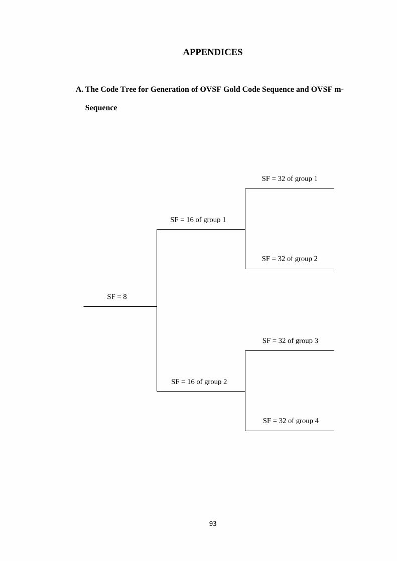
93
APPENDICES
A. The Code Tree for Generation of OVSF Gold Code Sequence and OVSF m-
Sequence
SF = 32 of group 1
SF = 32 of group 2
SF = 16 of group 1
SF = 32 of group 3
SF = 32 of group 4
SF = 16 of group 2
SF = 8

94
SF = 256 of group 1
SF = 256 of group 2
SF = 256 of group 3
SF = 256 of group 4
SF = 128 of group 1
SF = 128 of group 2
SF = 256 of group 5
SF = 256 of group 6
SF = 256 of group 7
SF = 256 of group 8
SF = 128 of group 3
SF = 128 of group 4
SF = 64 of group 1
SF = 64 of group 2
SF = 256 of group 9
SF = 256 of group 10
SF = 256 of group 11
SF = 256 of group 12
SF = 128 of group 5
SF = 128 of group 6
SF = 256 of group 13
SF = 256 of group 14
SF = 256 of group 15
SF = 256 of group 16
SF = 128 of group 7
SF = 128 of group 8
SF = 64 of group 3
SF = 64 of group 4
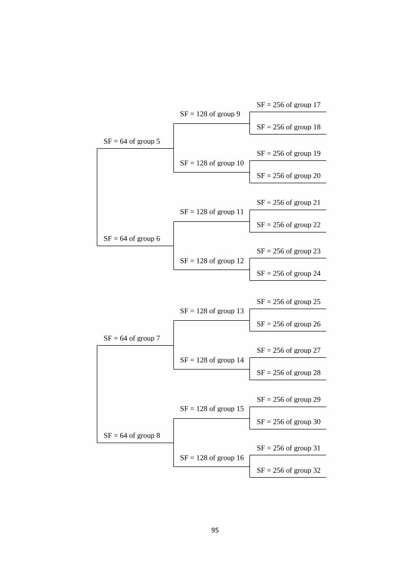
95
SF = 256 of group 17
SF = 256 of group 18
SF = 256 of group 19
SF = 256 of group 20
SF = 128 of group 9
SF = 128 of group 10
SF = 256 of group 21
SF = 256 of group 22
SF = 256 of group 23
SF = 256 of group 24
SF = 128 of group 11
SF = 128 of group 12
SF = 64 of group 5
SF = 64 of group 6
SF = 256 of group 25
SF = 256 of group 26
SF = 256 of group 27
SF = 256 of group 28
SF = 128 of group 13
SF = 128 of group 14
SF = 256 of group 29
SF = 256 of group 30
SF = 256 of group 31
SF = 256 of group 32
SF = 128 of group 15
SF = 128 of group 16
SF = 64 of group 7
SF = 64 of group 8

96
B. Notation for OVSF Gold Code Sequence and OVSF m-sequence in the code tree
OVSF code sequence Notations
SF = 8 8
SF = 16 of group 1 8 8
SF = 16 of group 2 8 8
SF = 32 of group 1 8 8 8 8
SF = 32 of group 2 8 8 8
8
SF = 32 of group 3 8 8 8
8
SF = 32 of group 4 8 8 8
SF = 64 of group 1 8 8 8 8 8 8 8 8
SF = 64 of group 2 8 8 8 8 8
8 8
8
SF = 64 of group 3 8 8 8
8 8 8 8
8
SF = 64 of group 4 8 8 8
8 8
8 8 8
SF = 64 of group 5 8 8 8
8 8 8 8
8
SF = 64 of group 6 8 8 8
8 8 8
8 8
SF = 64 of group 7 8 8 8 8
8 8
SF = 64 of group 8 8 8 8
8 8 8 8
SF = 128 of group 1 8 8 8 8 8 8 8 8 8 8 8 8 8 8 8 8
SF = 128 of group 2 8 8 8 8 8 8 8 8 8
8 8
8 8
8 8
8
SF = 128 of group 3 8 8 8 8 8
8 8
8 8 8 8 8 8
8 8
8
SF = 128 of group 4 8 8 8 8 8
8 8
8 8
8 8
8 8 8 8 8
SF = 128 of group 5 8 8 8
8 8 8 8
8 8 8 8
8 8 8 8
8
SF = 128 of group 6 8 8 8
8 8 8 8
8 8
8 8 8 8
8 8 8
SF = 128 of group 7 8 8 8
8 8
8 8 8 8 8 8
8 8
8 8 8
SF = 128 of group 8 8 8 8
8 8
8 8 8 8
8 8 8 8 8 8
8
SF = 128 of group 9 8 8 8
8 8 8 8
8 8 8 8
8 8 8 8
8
SF = 128 of group 10 8 8 8
8 8 8 8
8 8 8
8 8 8 8
8 8
SF = 128 of group 11 8 8 8
8 8 8
8 8 8 8 8
8 8 8
8 8
SF = 128 of group 12 8 8 8
8 8 8
8 8 8 8
8 8 8 8 8
8
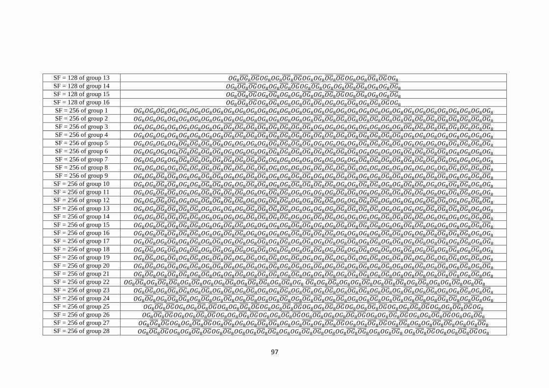
97
SF = 128 of group 13 8 8 8 8
8 8 8 8 8 8
8 8
SF = 128 of group 14 8 8 8 8
8 8 8 8 8
8 8 8 8
8
SF = 128 of group 15 8 8 8
8 8 8 8 8
8 8 8 8 8
8
SF = 128 of group 16 8 8 8
8 8 8 8
8 8 8 8 8
8 8
SF = 256 of group 1 8 8 8 8 8 8 8 8 8 8 8 8 8 8 8 8 8 8 8 8 8 8 8 8 8 8 8 8 8 8 8 8
SF = 256 of group 2 8 8 8 8 8 8 8 8 8 8 8 8 8 8 8 8 8
8 8
8 8
8 8
8 8
8 8
8 8
8 8
8
SF = 256 of group 3 8 8 8 8 8 8 8 8 8
8 8
8 8
8 8
8 8 8 8 8 8 8 8 8 8
8 8
8 8
8 8
8
SF = 256 of group 4 8 8 8 8 8 8 8 8 8
8 8
8 8
8 8
8 8
8 8
8 8
8 8
8 8 8 8 8 8 8 8 8
SF = 256 of group 5 8 8 8 8 8
8 8
8 8 8 8 8 8
8 8
8 8 8 8 8 8
8 8
8 8 8 8 8 8
8 8
8
SF = 256 of group 6 8 8 8 8 8
8 8
8 8 8 8 8 8
8 8
8 8
8 8
8 8 8 8 8 8
8 8
8 8 8 8 8
SF = 256 of group 7 8 8 8 8 8
8 8
8 8
8 8
8 8 8 8 8 8 8 8 8 8
8 8
8 8
8 8
8 8 8 8 8
SF = 256 of group 8 8 8 8 8 8
8 8
8 8
8 8
8 8 8 8 8 8
8 8
8 8 8 8 8 8 8 8 8 8
8 8
8
SF = 256 of group 9 8 8 8
8 8 8 8
8 8 8 8
8 8 8 8
8 8 8 8
8 8 8 8
8 8 8 8
8 8 8 8
8
SF = 256 of group 10 8 8 8
8 8 8 8
8 8 8 8
8 8 8 8
8 8
8 8 8 8
8 8 8 8
8 8 8 8
8 8 8
SF = 256 of group 11 8 8 8
8 8 8 8
8 8
8 8 8 8
8 8 8 8 8 8
8 8 8 8
8 8
8 8 8 8
8 8 8
SF = 256 of group 12 8 8 8
8 8 8 8
8 8
8 8 8 8
8 8 8 8
8 8 8 8
8 8 8 8 8 8
8 8 8 8
8
SF = 256 of group 13 8 8 8
8 8
8 8 8 8 8 8
8 8
8 8 8 8 8 8
8 8
8 8 8 8 8 8
8 8
8 8 8
SF = 256 of group 14 8 8 8
8 8
8 8 8 8 8 8
8 8
8 8 8 8
8 8 8 8 8 8
8 8
8 8 8 8 8 8
8
SF = 256 of group 15 8 8 8
8 8
8 8 8 8
8 8 8 8 8 8
8 8 8 8
8 8
8 8 8 8
8 8 8 8 8 8
8
SF = 256 of group 16 8 8 8
8 8
8 8 8 8
8 8 8 8 8 8
8 8
8 8 8 8 8 8
8 8 8 8
8 8
8 8 8
SF = 256 of group 17 8 8 8
8 8 8 8
8 8 8 8
8 8 8 8
8 8 8 8
8 8 8 8
8 8 8 8
8 8 8 8
8
SF = 256 of group 18 8 8 8
8 8 8 8
8 8 8 8
8 8 8 8
8 8 8
8 8 8 8
8 8 8 8
8 8 8 8
8 8
SF = 256 of group 19 8 8 8
8 8 8 8
8 8 8
8 8 8 8
8 8 8 8 8
8 8 8 8
8 8 8
8 8 8 8
8 8
SF = 256 of group 20 8 8 8
8 8 8 8
8 8 8
8 8 8 8
8 8 8 8
8 8 8 8
8 8 8 8 8
8 8 8 8
8
SF = 256 of group 21 8 8 8
8 8 8
8 8 8 8 8
8 8 8
8 8 8 8 8
8 8 8
8 8 8 8 8
8 8 8
8 8
SF = 256 of group 22 8 8 8
8 8 8
8 8 8 8 8
8 8 8
8 8 8 8
8 8 8 8 8
8 8 8
8 8 8 8 8
8
SF = 256 of group 23 8 8 8
8 8 8
8 8 8 8
8 8 8 8 8
8 8 8 8
8 8 8
8 8 8 8
8 8 8 8 8
8
SF = 256 of group 24 8 8 8
8 8 8
8 8 8 8
8 8 8 8 8
8 8 8
8 8 8 8 8
8 8 8 8
8 8 8
8 8
SF = 256 of group 25 8 8 8 8
8 8 8 8 8 8
8 8 8 8 8 8
8 8 8 8 8 8
8 8
SF = 256 of group 26 8 8 8 8
8 8 8 8 8 8
8 8 8 8 8
8 8 8 8 8 8
8 8 8 8
SF = 256 of group 27 8 8 8 8
8 8 8 8 8
8 8 8 8
8 8 8 8 8
8 8 8 8 8
8 8 8 8
8
SF = 256 of group 28 8 8 8 8
8 8 8 8 8
8 8 8 8
8 8 8 8
8 8 8 8
8 8 8 8 8
8 8

98
SF = 256 of group 29 8 8 8
8 8 8 8 8
8 8 8 8 8
8 8 8 8
8 8 8 8 8
8 8 8 8 8
8
SF = 256 of group 30 8 8 8
8 8 8 8 8
8 8 8 8 8
8 8 8 8
8 8 8 8
8 8 8 8 8
8 8
SF = 256 of group 31 8 8 8
8 8 8 8
8 8 8 8 8
8 8 8 8 8
8 8 8 8
8 8 8 8 8
8 8
SF = 256 of group 32 8 8 8
8 8 8 8
8 8 8 8 8
8 8 8 8 8
8 8 8 8 8
8 8 8 8 8
8

99
C. Matlab code/Simulink for HOVLS code sequence
C1. Generation of HOVLS code sequence
clc, clear all, close all;
%Code generation
n = 6;%number of register N = 2^n - 1;%length of the code
sim('L_Kas');
y1 = out_L_Kasami; %element of L Kasami
sim('PN_Out') y2 = out_PN; %element of m-sequence M=N-1;
for k = 1:N
B1(1,k)=y1(M+1) for i=1:M j=i+1; B1(j,k)=y1(i);
end for l=1:(M+1) y1(l) = B1(l,k);
end end
w = 0; x = N; for i = 1:N for j = 1:(M+1) M1(i,j) = B1(j,x); end w=w+1; z=abs(1-w); x=N-(M-z); end
M1_Box = M1;
for i = 1:N for j = 1:N M11(j,:,i)=M1_Box(i,:); end end
for zz = 1:N if zz == 1 for k = 1:N
B2(1,k)=y2(M+1);
for i=1:M j=i+1; B2(j,k)=y2(i); end for l=1:(M+1) y2(l) = B2(l,k);

100
end end w = 0; x = N; for i = 1:N for j = 1:(M+1) M2(i,j,zz) = B2(j,x);
end w=w+1; z=abs(1-w); x=N-(M-z); end M2_Box = M2; else y2 = M2_Box(zz for k = 1:N
B2(1,k)=y2(M+1);
for i=1:M j=i+1; B2(j,k)=y2(i); end for l=1:(M+1) y2(l) = B2(l,k); end end
w = 0; x = N; for i = 1:N for j = 1:(M+1) M2(i,j,zz) = B2(j,x);
end w=w+1; z=abs(1-w); x=N-(M-z); end end end
M12 = []; for i = 1:N M12(:,:,i) = bitxor(M11(:,:,i),M2(:,:,i));
end
for i = 1:N M12_aksen(:,:,i) = [M12(:,:,i);M11(i,:,i)]; end for i = 1:N Buffer_M12_aksen(:,1,i) = ~(M12_aksen(:,1,i)); end
MA = ones([(N+1) 1]); for j = 1:N for i = 1:(N-1) MB(:,i,j) = M12_aksen(:,(i+1),j);
end end
for i = 1:N

101
M12_bintang_1(:,:,i) = [MA MB(:,:,i)]; end
for i = 1:N M12_bintang_2(:,:,i) = [M12_bintang_1(:,:,i)
Buffer_M12_aksen(:,:,i)];
end
for j = 1:N HOVLS_Code(:,:,j) = 1 - (2.*M12_bintang_2(:,:,j));
end
C2. Generation of orthogonal Gold code sequence
clc, clear all, close all;
%Code generation n = 6;%number of register N = 2^n - 1;%length of the code sim('Gold_1'); y1 = out_Gold_1; sim('Gold_2') y2 = out_Gold_2; M=N-1;
for k = 1:N B1(1,k)=y1(M+1);
for i=1:M j=i+1; B1(j,k)=y1(i);
end for l=1:(M+1) y1(l) = B1(l,k);
end end
w = 0; x = N; for i = 1:N for j = 1:(M+1) M1(i,j) = B1(j,x); end w=w+1; z=abs(1-w); x=N-(M-z); end
M1_Box = M1; for i = 1:N for j = 1:N M11(j,:,i)=M1_Box(i,:); end end

102
for zz = 1:N if zz == 1 for k = 1:N B2(1,k)=y2(M+1); for i=1:M j=i+1; B2(j,k)=y2(i); end for l=1:(M+1) y2(l) = B2(l,k); end end
w = 0; x = N; for i = 1:N for j = 1:(M+1) M2(i,j,zz) = B2(j,x); end w=w+1; z=abs(1-w); x=N-(M-z); end M2_Box = M2; else y2 = M2_Box(zz,:); for k = 1:N B2(1,k)=y2(M+1); for i=1:M j=i+1; B2(j,k)=y2(i); end for l=1:(M+1) y2(l) = B2(l,k); end end
w = 0; x = N; for i = 1:N for j = 1:(M+1) M2(i,j,zz) = B2(j,x); end w=w+1; z=abs(1-w); x=N-(M-z); end end end
M12 = []; for i = 1:N M12(:,:,i) = bitxor(M11(:,:,i),M2(:,:,i)); end
MA = ones([N 1]);
for i = 1:N U(1,:,i) = [M11(1,:,i) 1]; end

103
for i = 1:N M12_Gold(:,:,i) = [M12(:,:,i) MA]; goldn(:,:,i) = [U(1,:,i); M12_Gold(:,:,i)]; end
for j = 1:N Orthog_Gold(:,:,j) = 1 - (2.*goldn(:,:,j)); end
C3. Generation of orthogonal m-sequence
clc, clear all, close all;
%Code generation n = 6;%number of register N = 2^n - 1;%length of the code
sim('m_sequence_1'); y1 = out_m_sequence_1;
sim('m_sequence_')% y2 = out_m_sequence_2; M=N-1;
for k = 1:N B1(1,k)=y1(M+1);
for i=1:M j=i+1; B1(j,k)=y1(i);
end for l=1:(M+1) y1(l) = B1(l,k);
end end
w = 0; x = N; for i = 1:N for j = 1:(M+1) M1(i,j) = B1(j,x);
end w=w+1; z=abs(1-w); x=N-(M-z); end
M1_Box = M1;
for i = 1:N for j = 1:N M11(j,:,i)=M1_Box(i,:); end end

104
for zz = 1:N if zz == 1 for k = 1:N B2(1,k)=y2(M+1); for i=1:M j=i+1; B2(j,k)=y2(i); end for l=1:(M+1) y2(l) = B2(l,k); end end
w = 0; x = N; for i = 1:N for j = 1:(M+1) M2(i,j,zz) = B2(j,x); end w=w+1; z=abs(1-w); x=N-(M-z); end M2_Box = M2; else y2 = M2_Box(zz,:); for k = 1:N B2(1,k)=y2(M+1); for i=1:M j=i+1; B2(j,k)=y2(i); end for l=1:(M+1) y2(l) = B2(l,k); end end
w = 0; x = N; for i = 1:N for j = 1:(M+1) M2(i,j,zz) = B2(j,x); end w=w+1; z=abs(1-w); x=N-(M-z); end end end
M12 = []; for i = 1:N M12(:,:,i) = bitxor(M11(:,:,i),M2(:,:,i)); end
for i = 1:N M12_aksen(:,:,i) = [M12(:,:,i);M11(i,:,i)]; end

105
for i = 1:N Buffer_M12_aksen(:,1,i) = ~(M12_aksen(:,1,i)); end
MA = ones([(N+1) 1]);
for j = 1:N for i = 1:(N-1) MB(:,i,j) = M12_aksen(:,(i+1),j); end end
for i = 1:N M12_bintang_1(:,:,i) = [MA MB(:,:,i)]; end
for i = 1:N M12_bintang_2(:,:,i) = [M12_bintang_1(:,:,i)
Buffer_M12_aksen(:,:,i)]; end
for j = 1:N O_m_seq(:,:,j) = 1 - (2.*M12_bintang_2(:,:,j)); end

106
C4. Block of Simulink for CDMA system
C4.1 Block of Simulink for Base Transceiver
Block of base transceiver (BTS) contains 64 of the following block of Simulink
of users in CDMA system. This block was used for simulation of users at BTS of
fixed length orthogonal code sequence. The block was also used for users R at BTS
for simulation of OVSF code sequences.
C4.2 Block of Simulink for desired user‟s receiver
The following block was used for desired user‟s receiver for simulation of fixed
length orthogonal code sequence. The block was also used for desired user R‟s
receiver for simulation of OVSF code sequences.

107
C4.3 Block of Simulink for users 2R at BTS
C4.4 Block of Simulink for desired user‟s receiver for user 2R