
nx230_s1
63
SERVICE MANUAL CONFIDENTIAL Color Inkjet Printer Epson Stylus TX235/Epson Stylus SX230/Epson ME OFFICE 535 Epson Stylus NX230/Epson Stylus TX230W/Epson Stylus TX235W/ Epson Stylus SX235W/Epson Stylus NX330/Epson Stylus TX430W/ Epson Stylus SX430W/Epson Stylus SX435W/Epson ME OFFICE 570W Epson Stylus NX430/Epson Stylus TX435W/Epson Stylus SX440W/ Epson Stylus SX445W SEMF10-011
-
Upload
julio-cesar-orozco-pacheco -
Category
Documents
-
view
915 -
download
31
Transcript of nx230_s1
SERVICE MANUAL
Color Inkjet Printer
Epson Stylus TX235/Epson Stylus SX230/Epson ME OFFICE 535Epson Stylus NX230/Epson Stylus TX230W/Epson Stylus TX235W/Epson Stylus SX235W/Epson Stylus NX330/Epson Stylus TX430W/Epson Stylus SX430W/Epson Stylus SX435W/Epson ME OFFICE 570WEpson Stylus NX430/Epson Stylus TX435W/Epson Stylus SX440W/Epson Stylus SX445W
CONFIDENTIAL
SEMF10-011

Notice:All rights reserved. No part of this manual may be reproduced, stored in a retrieval system, or transmitted in any form or by any means, electronic, mechanical, photocopying, recording, or otherwise, without the prior written permission of SEIKO EPSON CORPORATION.All effort have been made to ensure the accuracy of the contents of this manual. However, should any errors be detected, SEIKO EPSON would greatly appreciate being informed of them.The contents of this manual are subject to change without notice.The above not withstanding SEIKO EPSON CORPORATION can assume no responsibility for any errors in this manual or the consequences thereof.
EPSON is a registered trademark of SEIKO EPSON CORPORATION.
Note :Other product names used herein are for identification purpose only and may be trademarks or registered trademarks of their respective owners. EPSON disclaims any and all rights in those marks.
Copyright © 2011 SEIKO EPSON CORPORATIONI&I CS Quality Assurance Department
Confidential

Safety PrecautionsAll safety procedures described here shall be strictly adhered to by all parties servicing and maintaining this product.
DANGER
Strictly observe the following cautions. Failure to comply could result in serious bodily injury or loss of life.
1. Always disconnect the product from the power source and peripheral devices when servicing the product or performing maintenance.
2. When performing works described in this manual, do not connect to a power source until instructed to do so. Connecting to a power source causes high voltage in the power supply unit and some electronic components even if the product power switch is off. If you need to perform the work with the power cable connected to a power source, use extreme caution to avoid electrical shock.
WARNINGStrictly observe the following cautions. Failure to comply may lead to personal injury or loss of life.
1. Always wear protective goggles for disassembly and reassembly to protect your eyes from ink in working. If any ink gets in your eyes, wash your eyes with clean water and consult a doctor immediately.
2. When using compressed air products; such as air duster, for cleaning during repair and maintenance, the use of such products containing flammable gas is prohibited.
PRECAUTIONSStrictly observe the following cautions. Failure to comply may lead to personal injury or damage of the product.
1. Repairs on Epson product should be performed only by an Epson certified repair technician.
2. No work should be performed on this product by persons unfamiliar with basic safety knowledge required for electrician.
3. The power rating of this product is indicated on the serial number/rating plate. Never connect this product to the power source whose voltages is different from the rated voltage.
4. Replace malfunctioning components only with those components provided or approved by Epson; introduction of second-source ICs or other non-approved components may damage the product and void any applicable Epson warranty.
5. The capacitors on the Main Board may be electrically charged right after the power turns off or after driving motors which generates counter electromotive force such as when rotating the PF Roller or when moving the CR Unit. There is a risk to damage the Main Board if the Head FFC is short-circuited with the capacitors on the Main Board electrically charged, therefore, after the power turns off or after motors are driven, leave the printer untouched for approximately 30 seconds to discharge the capacitors before starting disassembly/reassembly.
6. To prevent the circuit boards from short-circuiting, be careful about the following when handling FFC or cables.
When handling FFC, take care not to let the terminal section of FFC touch metal parts.When connecting cables/FFC to the connectors on circuit boards, connect them straight to the connectors to avoid slant insertion.
Confidential

7. In order to protect sensitive microprocessors and circuitry, use static discharge equipment, such as anti-static wrist straps, when accessing internal components.
8. Do not tilt this product immediately after initial ink charge, especially after performing the ink charge several times. Doing so may cause ink to leak from the product because it may take some time for the waste ink pads to completely absorb ink wasted due to the ink charge.
9. Never touch the ink or wasted ink with bare hands. If ink comes into contact with your skin, wash it off with soap and water immediately. If you have a skin irritation, consult a doctor immediately.
10. When disassembling or assembling this product, make sure to wear gloves to avoid injuries from metal parts with sharp edges.
11. Use only recommended tools for disassembling, assembling or adjusting the printer.
12. Observe the specified torque when tightening screws.
13. Be extremely careful not to scratch or contaminate the following parts.
Nozzle plate of the PrintheadCR ScalePF ScaleCoated surface of the PF RollerGearsRollersLCDScanner SensorExterior parts
14. Never use oil or grease other than those specified in this manual. Use of different types of oil or grease may damage the component or give bad influence on the printer function.
15. Apply the specified amount of grease described in this manual.
16. Make the specified adjustments when you disassemble the printer.
17. When cleaning this product, follow the procedure described in this manual.
18. When transporting this product after filling the ink in the printhead, pack the printer without removing the ink cartridges in order to prevent the printhead from drying out.
19. Make sure to install antivirus software in the computers used for the service support activities.
20. Keep the virus pattern file of antivirus software up-to-date.
21. When disassembling/reassembling this product, if you find adhesive power of the double-sided tape which secure the parts or FFC is not enough, replace the tape with new one and attach it correctly to the specified points where the parts or FFC should be secured.
22. Unless otherwise specified in this manual, the labels attached on the returned product should be transferred to the corresponding attachment positions on the new one referring to the labels on the returned product.
Confidential

About This ManualThis manual, consists of the following chapters, is intended for repair service personnel and includes information necessary for properly performing maintenance and servicing the product.
CHAPTER 1. TROUBLESHOOTINGDescribes the step-by-step procedures for the troubleshooting.
CHAPTER 2. DISASSEMBLY / REASSEMBLYDescribes the disassembly/reassembly procedures for main parts/units of the product, and provides the standard operation time for servicing the product.
CHAPTER 3. ADJUSTMENTDescribes the required adjustments for servicing the product.
CHAPTER 4. MAINTENANCEDescribes maintenance items and procedures for servicing the product.
CHAPTER 5. REFURBISHMENTDescribes refurbishing work of the product and its purpose.
CHAPTER 6. APPENDIXProvides the following additional information for reference:
• Connector Diagram• Protection for Transportation
Symbols Used in this Manual
Various symbols are used throughout this manual either to provide additional information on a specific topic or to warn of possible danger present during a procedure or an action. Pay attention to all symbols when they are used, and always read explanation thoroughly and follow the instructions.
Indicates an operating or maintenance procedure, practice or condition that, if not strictly observed, could result in serious injury or loss of life.
Indicates an operating or maintenance procedure, practice, or condition that, if not strictly observed, could result in bodily injury, damage or malfunction of equipment.
May indicate an operating or maintenance procedure, practice or condition that is necessary to accomplish a task efficiently. It may also provide additional information that is related to a specific subject, or comment on the results achieved through a previous action.
For Chapter 2 “Disassembly/Reassembly”, symbols other than indicated above are used to show additional information for disassembly/reassembly. For the details on those symbols, see "2.2 Disassembly/Reassembly Procedures (p26)".
Confidential

Revision Status
Revision Date of Issue Description
A April 22, 2011 First Release
B June 22, 2011 Revised ContentsPreface
" Safety Precautions (p3)" has been added.Chapter 1
Made change in "1.1.1 Troubleshooting Workflow (p10)".Made change in "1.3.1 Displaying the Fatal Error Code (p14)".Made change in "1.3.2 Printer Fatal Error Code (p15)".Made change in "1.3.3 Scanner Fatal Error Code (p18)".
Chapter 2Made change in "2.1.3 Locations of the Parts/Units (p21)".Made change in "2.1.4 Standard Operation Time for Servicing the Product (p24)".Made change in "2.2.1 Disassembly Flowchart (p27)".Caution in " Housing Left/Housing Right (p32)" has been added.Made change in " PS Unit (p32)".Made change in " Waste Ink Pad Assy (p32)".Made change in " Panel Housing Lower Assy (SX235W series) (p33)"." Panel Housing Lower Assy (SX440W series) (p33)" has been added." Panel Board w/Touch Panel (SX440W series) (p34)" has been added.Made change in " Main Board (p34)".Made change in " LD Roller Assy (1) (p34)"." Paper Guide Front Porous Pad (p35)" has been added.Made change in " Paper Guide Lower Porous Pad (p35)".Made change in " PF Driven Pulley Assy / PF Timing Belt (p35)".Made change in " Main Frame Assy (p36)"." PF Grounding Spring (p37)" has been added." Wireless LAN Module (SX235W series/SX430W series/SX440W series) (p37)" has been added.Made change in " Main Board (p38)".Made change in " Panel Unit (1) (p38)".Made change in " Panel Unit (2) (p38)".Made change in " Inside the Panel Unit (SX230 series/SX235W series/SX430W series) (p38)"." Inside the Panel Unit (SX440W series only) (p38)" has been added.Made change in " Card Slot Board (SX230 series/SX430W series/SX440W series) (p39)".Made change in " Head FFC (2) (p39)".Made change in " PS Unit (p40)".Made change in " PF Motor (p40)".Made change in " Scanner FFC (p40)".Made change in " PF Encoder Sensor (p40)".
Chapter 3Made change in "3.1 Required Adjustments (p42)".Made change in "3.2.3 Scanner Motor Heat Protection Control (p48)".Made change in "3.3.1 Checking the Platen Gap (p49)"."3.3.2 CR/PF Belt Tension Check (p50)" has been added.
Confidential

Revision Date of Issue Description
B June 22, 2011 Chapter 4"4.2 Lubrication Points and Instructions (p54)"ASP supply status and lubrication status when supplied as ASP has been added for all lubrication points."4-3 Lubrication of the Frame Base (3) (p54)" has been added."4-13 Lubrication of the Scanner Carriage (2) (p57)" has been added."4-15 Lubrication of Scanner Motor, Combination Gear 14.4,10.8 and Combination Gear 13.8,9.66 (p57)" has been added."4-14 Lubrication of the Panel Stand (p57)" has been added.
Chapter 5Made change in "5.1.1 Ink Discharge (p59)".
Chapter 6Made change in "6.2.1 Securing the CR Unit (p62)"."6.2.2 Securing the Paper Support Assy (p63)" has been added.
Confidential

8
Epson Stylus SX230 series / SX235W series / SX430W series / SX440W series Revision B
Confidential
ContentsChapter 1 Troubleshooting
1.1 Troubleshooting....................................................................................................................................................... 101.1.1 Troubleshooting Workflow ............................................................................................................................ 10
1.2 Power-On Sequence ................................................................................................................................................ 121.3 Fatal Error Code List ............................................................................................................................................... 14
1.3.1 Displaying the Fatal Error Code..................................................................................................................... 141.3.2 Printer Fatal Error Code ................................................................................................................................. 151.3.3 Scanner Fatal Error Code ............................................................................................................................... 18
Chapter 2 Disassembly/Reassembly
2.1 Overview ................................................................................................................................................................. 202.1.1 Tools ............................................................................................................................................................... 202.1.2 Jigs .................................................................................................................................................................. 20
2.1.2.1 Making the Spring Hook Jig .................................................................................................................. 202.1.3 Locations of the Parts/Units ........................................................................................................................... 212.1.4 Standard Operation Time for Servicing the Product ...................................................................................... 24
2.2 Disassembly/Reassembly Procedures ..................................................................................................................... 262.2.1 Disassembly Flowchart................................................................................................................................... 272.2.2 Disassembly Flowchart (Printhead/Main Board) ........................................................................................... 31
2.3 Detailed Disassembly/Reassembly Procedure for each Part/Unit........................................................................... 322.4 Routing FFCs/cables ............................................................................................................................................... 38
Chapter 3 Adjustment
3.1 Required Adjustments ............................................................................................................................................. 423.2 Adjustment Program................................................................................................................................................ 47
3.2.1 Operating Environment .................................................................................................................................. 473.2.2 Details of the Adjustment Program ................................................................................................................ 47
3.2.2.1 CR Motor Heat Protection Control / PF Motor Heat Protection Control .............................................. 473.2.3 Scanner Motor Heat Protection Control ......................................................................................................... 48
3.3 Mechanism Adjustment / Check ............................................................................................................................. 493.3.1 Checking the Platen Gap ................................................................................................................................ 493.3.2 CR/PF Belt Tension Check............................................................................................................................. 50
Chapter 4 Maintenance
4.1 Overview ................................................................................................................................................................. 534.1.1 Cleaning.......................................................................................................................................................... 534.1.2 Lubrication...................................................................................................................................................... 53
4.2 Lubrication Points and Instructions......................................................................................................................... 54
Chapter 5 Refurbishment
5.1 Overview ................................................................................................................................................................. 595.1.1 Ink Discharge.................................................................................................................................................. 59
Chapter 6 Appendix
6.1 Connector Diagram ................................................................................................................................................. 616.2 Protection for Transportation .................................................................................................................................. 62
6.2.1 Securing the CR Unit...................................................................................................................................... 626.2.2 Securing the Paper Support Assy ................................................................................................................... 63

CHAPTER
1TROUBLESHOOTING
Confidential

Tro
Epson Stylus SX230 series / SX235W series / SX430W series / SX440W series Revision B
1.1 TroubleshootingThis section describes the troubleshooting workflow and fatal error information.
1.1.1 Troubleshooting WorkflowThe following page describes the troubleshooting workflow. Follow the flow when troubleshooting problems.
In this chapter, the product names are called as follows:SX230 series: Epson Stylus TX235/Epson Stylus SX230/Epson ME OFFICE 535SX235W series: Epson Stylus NX230/Epson Stylus TX235W/Epson Stylus SX235W/
Epson Stylus TX230WSX430W series: Epson Stylus NX330/Epson Stylus TX430W/Epson Stylus SX430W/
Epson Stylus SX435W/Epson ME OFFICE 570WSX440W series: Epson Stylus NX430/Epson Stylus TX435W/Epson Stylus SX440W/
Epson Stylus SX445W
Confidential
ubleshooting Troubleshooting 10

Epson Stylus SX230 series / SX235W series / SX430W series / SX440W series Revision B
ConfidentialTroubleshooting Troubleshooting Workflow 11
If the reason for the return is evident, first check the phenomenon user claims recurs, then proceed to the troubleshooting.This flowchart is compiled based on the following contents. • Our experience regarding the quality problem.• ESK’s repair data.• Printer Mechanism specification for Epson Stylus SX230 series /
SX235W series / SX430W series / SX440W series.
Fatal error
Please refer to " 1.3 Fatal Error Code List (p14)".
Maintenance error
[Occurrence Condition]This error occurs when maintenance counter in EEPROM exceeds the specified value.
[Major Occurrence Timing]• Power-on timing• Print start timing• Cleaning timing• Ink Cartridge replacement
timing
[Troubleshooting]• Porous Pad replacement &
Maintenance counter reset
Ink End error
[Occurrence Condition]This error occurs when ink in Ink Cartridge is empty.
[Major Occurrence Timing]• Power-on timing• Print start timing• Cleaning timing• Ink Cartridge replacement
timing
[Troubleshooting]• Ink Cartridge replacement
Ink Cartridge error
[Occurrence Condition]This error occurs when the Ink Cartridge failed.
[Major Occurrence Timing]• Power-on timing• Print start timing• Cleaning timing• Ink Cartridge replacement
timing
[Major Troubleshooting]• Remove and reinstall Ink
Cartridge• Ink Cartridge replacement• CSIC Terminal (Holder Board
Assy) replacement • Holder Board Assy
replacement• Head FFC replacement• Main Board replacement
No Ink Cartridge error
[Occurrence Condition]This error occurs when Ink Cartridge is not installed.
[Major Occurrence Timing]• Power-on timing
[Troubleshooting]• Ink Cartridge installation
Paper Jam Fatal error
[Occurrence Condition]This error occurs when CR Unit is blocked by jammed paper.
[Major Occurrence Timing]• Power-on timing
[Major Troubleshooting]• Remove jammed paper
[NOTE]On this product, if CR Unit touches jammed paper, CR Unit moves back in the opposite direction so that customer can remove the paper. However, if CR Unit cannot move in this sequence, this error occurs.
Paper Jam error
[Occurrence Condition]This error occurs when top/bottom of paper is not detected by PE Sensor in the specified steps of paper loading / ejecting operation correctly.
[Major Occurrence Timing]• Power-on timing• Paper loading timing• Paper eject timing
[Major Troubleshooting]1 Perform paper eject operation
from operation panel.• Success
Starts paper feeding operation again if printer has print data.
• FailOccurs paper jam error again.
2 If fail in the above 1, remove the paper by opening Scanner Unit.
3 Perform paper eject operation from operation panel again.
• SuccessStarts paper feeding operation again if printer has print data.
• FailOccurs paper jam error again.
4 If fail in the above 3, check foreign material / part come-off / PE Sensor Lever / PE Sensor / Porous Pad on Paper Guide Front / Main board.
No Paper error
[Occurrence Condition]This error occurs when top of paper can not be detected correctly by PE Sensor in the specified steps up to completion of the paper loading operation.(No paper / No loading / large paper skew)
[Major Occurrence Timing]• Paper loading timing
[Major Troubleshooting]1 Set paper in ASF and perform
paper feed operation.2 If the paper stops before
reaching PE Sensor, remove it and check the paper condition.
3 A) If paper is OK, set paper in ASF and move edge guides to appropriate position, and perform 2 again.
B) If damage in the above 2,check foreign materials / parts come-off / partstransformation in paperpath.
4 If not resolved by 3-A & 3-B, check foreign material / Part come-off / surface condition of LD Roller or PF Roller / PE Sensor Lever / PE Sensor / Main Board / PF Motor.
Double Feed error
[Occurrence Condition]When manual duplex printing is selected using the printer driver, this error occurs if the actual paper length detected by PE Sensor does not match with the paper length specified in the printer driver. (The error occurs when the actual length is longer than the theoretical length specified in the driver.)
[Major Occurrence Timing]• Paper loading timing• Paper eject timing
[Troubleshooting]• PE Sensor Lever replacement• PE Sensor replacement
(Main Board replacement)• Main Board replacement
[NOTE]This error may occur in the manual duplex printing if the inverted sheet printed on the first side sticks to the second sheet when the first side printing is complete and the sheet is inverted and set to ASF to print on the other side.
Paper Size Unmatch error
[Occurrence Condition]This error occurs if the actual paper length detected by PE Sensor does not match with the paper length specified in the printer driver. (The error occurs no matter when the actual length is longer or shorter than the theoretical length specified in the driver.)
[Major Occurrence Timing]• Paper eject timing
[Troubleshooting]• PE Sensor Lever replacement• PE Sensor replacement
(Main Board replacement)• Main Board replacement
No Power*2
[Presumable Cause]• PS Unit damage• Main Board damage
[Major Troubleshooting]• PS Unit replacement• Main Board replacement
Poor Printing
[Phenomenon]• Poor printing quality• Ink stain on paper• Dot missing• Paper eject without printing
[Presumable Cause]• Driver / Panel mis-setting• Contamination of CR scale• Contamination of Printhead
cover• Printhead damage• Ink clogging of Printhead• Contamination on Cap Unit /
Wiper of Ink System Assy• Ink System Assy damage• Float of Porous Pad on Paper
Guide Front• Narrower/Wider PG
(out of standard)• PE Sensor Lever damage• PE Sensor damage
[Major Troubleshooting]• Driver / Panel re-setting• CR Scale replacement• Printhead cover cleaning• Printhead cleaning• Ink Cartridge replacement• Printhead replacement• Rubber cleaning of Cap Unit• Ink System Assy replacement• Porous Pad re-installation• Printer replacement• PE Sensor Lever replacement• PE Sensor replacement
(Main Board replacement)
Poor Paper Loading
[Presumable Cause]• Use of 3rd party media• Edge guide mis-setting• Foreign material• Part come-off• Contamination of LD Roller or
PF roller
[Major Troubleshooting]• Recommendation of EPSON
media• Edge guide re-setting• Foreign material removal• Part re-installation• Roller replacement
Abnormal Noise
[Presumable Cause]• Foreign material• Insufficient grease• Gear damage
[Major Troubleshooting]• Foreign material removal • Lubrication of grease• Gear replacement
Scanner failure
[Presumable Cause]• Contamination of Scanner Glass• Contamination of Document Pad• CIS Unit bonding failure• CIS Unit damage• Scanner Motor damage• Insufficient grease
[Major Troubleshooting]• Scanner Glass cleaning• Document Pad cleaning• Document Pad replacement• CIS Unit replacement• Scanner Motor replacement• Lubrication of grease
Finish*3
Turn on the power*1
1
1
Major problem without error message
Print check pattern
Is printing operation finished without trouble?
Start
No
Yes
Yes
No
Yes
No
Yes
*1: If the Hopper of ASF on the returned product touches the LD Roller, the initial ink charge has not been completed for the product yet.
*2: If the printer can turn on but turns off right away, the protection circuit may cut off the power due to an error such as a circuit failure.
*3: In case of “Not Trouble Found”, check fatal error code.
Major problem with error message
Major problem without error message
Is Power-on sequence finished without error?
NoIs scanning operation finished without trouble?
Standby condition
Does printer turn on the power?
Copy an image
Does an error occur when printing?
No
Yes

Tro
Epson Stylus SX230 series / SX235W series / SX430W series / SX440W series Revision B
1.2 Power-On SequenceThis section describes the power-on sequences in two conditions. The preconditions are as follows.
Condition 1: Normal power-on sequence (See Table 1-1.)Turning on the printer after turning it off without an error.Initial ink charge has finished and every cartridge has sufficient ink.No paper on the paper path.The Printhead is capped with the Cap Assy.The CR Unit is normally fixed by the Change Lever.Maintenance error recovery has never been performed.
Note 1: The rotation directions of the PF Motor are as follows.Clockwise: Paper is fed normallyCounterclockwise: Paper is fed backward
*2: The conditions of the CR lock are as follows.Red CR lock is setWhite CR lock is released
*3: The fatal error occurs if there is a problem such as the fuse blew.*4: Executed when the detected temperature is under 5 oC (41oF) by the thermistor on the Printhead.*5: The empty suction operation may occur depending on the situation.
Table 1-1. Condition 1: Normal Power-on Sequence
Operation*1CR Unit/PF Roller
movement and position*2
1. Printhead initialization and fuse inspection1-1.Initializes the Printhead, and checks for the fuse on the circuit boards in the printer.*3
2. Checking for waste ink overflow2-1.Checks the waste ink counter if the waste ink overflow is occurring.
3. Seeking the home position3-1.The CR Unit moves to the 80-digit side slowly and confirms it touches the Change Lever (CR lock).
3-2.The CR Unit moves to the 0-digit side slowly and confirms it touches the Right Frame.
3-3.After the PE Sensor checks if paper exists, the PF Motor rotates clockwise for one second and releases the CR lock.
3-4.While checking if the CR Unit does not touch the Change Lever (CR lock) or the foreign material, the CR Unit moves to the 80-digit side slowly until it touches the Left Frame.
3-5.The distance from the position where the CR Unit touched to the Left Frame is regarded as the standard distance from the origin position, and the home position is fixed.From then on, the CR Unit position is monitored according to the signals from the CR Encoder.
3-6.The CR Unit quickly moves to the ink end sensor detection position on the 0-digit side.
4. Low temperature operation sequence*4
4-1.The CR Unit moves to the 0-digit side slowly.
4-2.The CR Unit quickly moves back and forth between near the Change Lever and near the Left Frame for two times.
5. Detecting ink cartridge and initializing ink system*5
5-1.After checking the Ink End Sensor, the CR Unit moves to the ink detection position in the 0-digit side and detects the ink remaining.
5-2.The CR Unit returns to its home position.
Confidential
ubleshooting Power-On Sequence 12

Tro
Epson Stylus SX230 series / SX235W series / SX430W series / SX440W series Revision B
Condition 2: Power-on sequence after recovering from a paper jam error (See Table 1-2.)Turning on the printer after turning it off with a paper jam fatal error.There still remains paper on the paper path out of the detecting area of the PE Sensor.Maintenance error recovery has never been performed.
Note *1: “Paper exists” is detected when the CR Unit touches the paper. When “paper does not exist” is detected, the power-on sequence of condition 1 (Table 1-1) is executed from No.4.
*2: If the paper jam error cannot be solved after repeating the power-on sequence on condition 2 (Table 1-2) twice, the printer turns into the paper jam fatal error for the third time.
Table 1-2. Condition 2: Power-on Sequence after Recovering from a Paper Jam Error
OperationCR Unit/PF Roller
movement and position
Executes No.1 to No.3 on the normal power-on sequence (Table 1-1).4. Detecting remaining paper
4-1.5.The CR Unit returns to its home position.
4-2.The CR Unit moves to the 80-digit side and confirms there is no paper.*1
4-3.The CR Unit quickly returns to its home position, and displays on the LCD or with flashing LEDs that the paper jam error occurs.
When the user removes the paper and releases the paper jam error by panel operation, the normal power-on sequence from No.1 (Table 1-1) is executed again.*2
To recover from the maintenance error, the dedicated software that can be downloaded from the web site which can be accessed from STM3 is required.The printer operation related to the maintenance error recovery is as follows.• When the waste ink counter reaches the threshold value (1) for the first time and the
maintenance error occurs, the counter threshold of the maintenance error is changed to threshold value 2 after performing recovery from the maintenance error.
• After the threshold value (2) is enabled, the warning; to notify the possibility of ink leakage out of the printer, is displayed every time the waste ink counter increases by 1%.
• If the waste ink counter reaches the threshold value (2), the maintenance error occurs. Then, the waste ink counter is changed back to the threshold value (1) after recovering from the maintenance error, and the warning is displayed repeatedly according to the increment of the waste ink counter until the maintenance error occurs when the threshold value (2) is reached.(Recovery from the maintenance error can be performed up to the specified number of times.)
Confidential
ubleshooting Power-On Sequence 13

Tro
Epson Stylus SX230 series / SX235W series / SX430W series / SX440W series Revision B
1.3 Fatal Error Code ListThis section describes how to check the fatal error code, description, and the possible causes.
1.3.1 Displaying the Fatal Error CodeThe fatal error code is stored in the EEPROM on the Main Board and can be read out using the Adjustment Program. The code can be displayed on the LCD of the control panel by a special panel operation.
The following describes the panel operation for SX230 series, SX430W series and SX440W series to display the fatal error code.
Method of displaying the fatal error code
1. Press the following buttons simultaneously while the fatal error is occurring.
Home buttonStop buttonOK button
Figure 1-1. Displaying the Fatal Error Code (1)2. Check the displayed fatal error code.
Figure 1-2. Displaying the Fatal Error Code (2)
Since SX235W series does not have LCD, use the Adjustment Program to check the fatal error code.Only the printer fatal error code can be displayed by this panel operation.For the fatal error codes, descriptions, and their possible causes, see " 1.3.2 Printer Fatal Error Code (p15)".
Home button OK button Stop button
LCD display
Fatal error code
FATAL CODE:0x02
Confidential
ubleshooting Fatal Error Code List 14
Tro
Epson Stylus SX230 series / SX235W series / SX430W series / SX440W series Revision B
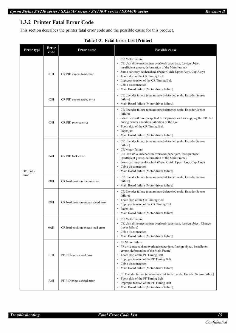
1.3.2 Printer Fatal Error CodeThis section describes the printer fatal error code and the possible cause for this product.
Table 1-3. Fatal Error List (Printer)
Error type Error code Error name Possible cause
DC motor error
01H CR PID excess load error
• CR Motor failure• CR Unit drive mechanism overload (paper jam, foreign object,
insufficient grease, deformation of the Main Frame)• Some part may be detached. (Paper Guide Upper Assy, Cap Assy)• Tooth skip of the CR Timing Belt• Improper tension of the CR Timing Belt• Cable disconnection• Main Board failure (Motor driver failure)
02H CR PID excess speed error• CR Encoder failure (contaminated/detached scale, Encoder Sensor
failure)• Main Board failure (Motor driver failure)
03H CR PID reverse error
• CR Encoder failure (contaminated/detached scale, Encoder Sensor failure)
• Some external force is applied to the printer such as stopping the CR Unit during printer operation, vibration or the like.
• Tooth skip of the CR Timing Belt• Paper jam• Main Board failure (Motor driver failure)
04H CR PID lock error
• CR Encoder failure (contaminated/detached scale, Encoder Sensor failure)
• CR Motor failure• CR Unit drive mechanism overload (paper jam, foreign object,
insufficient grease, deformation of the Main Frame)• Some part may be detached. (Paper Guide Upper Assy, Cap Assy)• Cable disconnection• Main Board failure (Motor driver failure)
08H CR load position reverse error• CR Encoder failure (contaminated/detached scale, Encoder Sensor
failure)• Main Board failure (Motor driver failure)
09H CR load position excess speed error
• CR Encoder failure (contaminated/detached scale, Encoder Sensor failure)
• Tooth skip of the CR Timing Belt• Improper tension of the CR Timing Belt• Paper jam• Main Board failure (Motor driver failure)
0AH CR load position excess load error
• CR Motor failure• CR Unit drive mechanism overload (paper jam, foreign object, Change
Lever failure)• Cable disconnection• Main Board failure (Motor driver failure)
F1H PF PID excess load error
• PF Motor failure• PF drive mechanism overload (paper jam, foreign object, insufficient
grease, deformation of the Main Frame)• Tooth skip of the PF Timing Belt• Improper tension of the PF Timing Belt• Cable disconnection• Main Board failure (Motor driver failure)
F2H PF PID excess speed error
• PF Encoder failure (contaminated/detached scale, Encoder Sensor failure)• Tooth skip of the PF Timing Belt• Improper tension of the PF Timing Belt• Main Board failure (Motor driver failure)
Confidential
ubleshooting Fatal Error Code List 15

Tro
Epson Stylus SX230 series / SX235W series / SX430W series / SX440W series Revision B
DC motor error
F3H PF PID reverse error
• PF Encoder failure (contaminated/detached scale, Encoder Sensor failure)• Tooth skip of the PF Timing Belt• Improper tension of the PF Timing Belt• Paper jam• Paper is pulled out from the ASF side when paper is fed• Main Board failure (Motor driver failure)
F4H PF PID lock error
• PF Encoder failure (contaminated/detached scale, Encoder Sensor failure)• PF Motor failure• PF drive mechanism overload (paper jam, foreign object, insufficient
grease, deformation of the Main Frame)• Cable disconnection• Main Board failure (Motor driver failure)
F8H PF load position reverse error• PF Encoder failure (contaminated/detached scale, Encoder Sensor failure)• Tooth skip of the PF Timing Belt• Improper tension of the PF Timing Belt
F9H PF load position excess speed error
• PF Encoder failure (contaminated/detached scale, Encoder Sensor failure)• Tooth skip of the PF Timing Belt• Improper tension of the PF Timing Belt• Main Board failure (Motor driver failure)
FAH PF load position excess load error
• PF Motor failure• PF drive mechanism overload (paper jam, foreign object)• Tooth skip of the PF Timing Belt• Improper tension of the PF Timing Belt• Cable disconnection
FCH PF load position error
• PF Encoder failure (contaminated/detached scale, Encoder Sensor failure)• PF Motor failure• PF drive mechanism overload (paper jam, foreign object)• Cable disconnection
Motor drive time error
D1H CR (PID) driving time error • Main Board failure (Firmware failure)
D2H CR (load position) driving time error• Change Lever failure• CR Motor failure• Main Board failure (Motor driver failure)
D3H PF (PID) driving time error • Main Board failure (Firmware failure)
D4H PF (BS) driving time error• Change Lever failure• CR Motor failure• Main Board failure (Motor driver failure)
Printhead system error
40H Transistor temperature error • Main Board failure
41H X-Hot detect error (pre printing)• Printhead failure• Main Board failure
42H X-Hot detect error (after flushing)
43H Head temperature error
Sequence error
50H Home position error
• Foreign object• Deformation of the Main Frame• Change Lever failure• Paper jam
56H Contact error at ink replacement timing(Power-off)
• Foreign object• Ink Cartridges are not installed correctly• Paper jam
Table 1-3. Fatal Error List (Printer)
Error type Error code Error name Possible cause
Confidential
ubleshooting Fatal Error Code List 16

Tro
Epson Stylus SX230 series / SX235W series / SX430W series / SX440W series Revision B
Sequence error 5BH Insoluble paper jam error
• Foreign object• Deformation of the Main Frame• Change Lever failure• Paper jam
Ink device error
B0H - CFH Ink device error
• Ink Cartridge failure• Holder Board Assy failure (CSIC Terminal failure/CR Contact Module
failure)• Main Board failure
Circuit error 80H Circuit error (include blowout of a fuse) • Main Board failure
Table 1-3. Fatal Error List (Printer)
Error type Error code Error name Possible cause
Confidential
ubleshooting Fatal Error Code List 17

Tro
Epson Stylus SX230 series / SX235W series / SX430W series / SX440W series Revision B
1.3.3 Scanner Fatal Error CodeThis section describes the scanner fatal error code and the possible cause for this product.
Note *1: The home seek pattern and the white standard pattern are attached on the back of the Scanner Housing Upper near the home position.
*2: The rack section is the linearly-arranged toothed area on the Scanner Housing Lower. (See Fig. 1-3.)
Figure 1-3. Rack section
Table 1-4. Fatal Error List (Scanner)Error code Error name Possible cause
10H Home position detection error
• CIS Module failure• Scanner Housing Upper failure (home seek pattern*1 is dirty)• Scanner Housing Lower failure (the rack section*2 is damaged)• Scanner Motor failure• Insufficient grease• Foreign object• FFC disconnection/failure• Main Board failure
20H LED lightning error
• CIS Module failure• Foreign object• Scanner Housing Upper failure (white standard pattern*1 is dirty)• Main Board failure
Scanner Housing Lower
Rack section
Confidential
ubleshooting Fatal Error Code List 18

CHAPTER
2DISASSEMBLY/REASSEMBLY
Confidential

Disa
Epson Stylus SX230 series / SX235W series / SX430W series / SX440W series Revision B
2.1 Overview
This chapter describes procedures for disassembling the main parts/units of SX230 series, SX235W series, SX430W series and SX440W series. Unless otherwise specified, disassembled parts/units can be reassembled by reversing the disassembly procedure. See the cautions or tips for disassembly/reassembly described in "2.3 Detailed Disassembly/Reassembly Procedure for each Part/Unit (p32)".Read the "Safety Precautions(p3)" before disassembling and reassembling.When you have to remove units or parts that are not described in this chapter, see the exploded diagrams of SPI (Service Parts Information).
2.1.1 ToolsUse only specified tools to avoid damaging the printer.
Note 1: Some of the tools listed above are commercially available.2: EPSON provides the tools listed with EPSON part code.
2.1.2 Jigs
Note *: If performing the disassembling/reassembling procedure is difficult using tweezers such as when reassembling " Cap Lever/Cap Assy (p35)", the spring hook jig helps you to remove/attach the spring easier.
2.1.2.1 Making the Spring Hook JigFold a clip (commercial item) as shown in Fig. 2-1.
Figure 2-1. Making the Spring Hook Jig
In this chapter, the product names are called as follows:SX230 series: Epson Stylus TX235/Epson Stylus SX230/Epson ME OFFICE 535SX235W series: Epson Stylus NX230/Epson Stylus TX235W/Epson Stylus SX235W/
Epson Stylus TX230WSX430W series: Epson Stylus NX330/Epson Stylus TX430W/Epson Stylus SX430W/
Epson Stylus SX435W/Epson ME OFFICE 570WSX440W series: Epson Stylus NX430/Epson Stylus TX435W/Epson Stylus SX440W/
Epson Stylus SX445W
Name Availability EPSON Part Code
(+) Phillips screwdriver #1 O 1080530(+) Phillips screwdriver #2 O ---Flathead screwdriver O ---Flathead Precision screwdriver #1 O ---Tweezers O ---Longnose pliers O ---Acetate tape --- 1003963
Name Quantity EPSON Part Code
Spring hook jig* 1 Can be made with a commercial item See " Making the Spring Hook Jig (p20)".Thickness gauge (1.5 mm) 2 Commercially availableThickness gauge (2.0 mm) 2 Commercially availableSonic tension meter 1 1294120
Before folding
Fold here
Clip
40 mm or moreAfter folding
Fold appropriate length to hitch a spring.
Clip
Confidential
ssembly/Reassembly Overview 20

Disa
Epson Stylus SX230 series / SX235W series / SX430W series / SX440W series Revision B
2.1.3 Locations of the Parts/UnitsThis section shows the locations of the main parts/units of SX230 series, SX235W series, SX430W series and SX440W series.
Exterior parts
Figure 2-2. Exterior Parts
The parts/units which can not be seen in the following pictures are indicated in dotted lines ( ).
No. Name No. Name
1 Housing Rear (p27)
4
• SX440W series (p 28)Panel Board w/ Touch Panel (p28)/Panel Housing Upper Assy (p28)/Panel Housing Lower Assy (p28)2 Tray Front Assy (p27)
3 Frame Base Assy (p28)
4
Panel Unit• SX230 series / SX430W series (p 28)
Panel Board (p29) / Panel Buttons (p29) / LCD (p29) /Panel Housing Upper Assy (p29) / Panel Housing Lower Assy (p29)
• SX235W series (p 28)Panel Board Assy (p28) / Panel Buttons (p28) / Panel Housing Upper Assy (p28) / Panel Housing Lower Assy (p28)
5 Hinge (p27)
6 Housing Right (p27)
7 Scanner Unit (p27)
8 Housing Left (p27)
9
Paper Support Assy (p27)
1
2 3 4
Front
5
6
Right
8
7Left
9
Rear
Confidential
ssembly/Reassembly Overview 21

Disa
Epson Stylus SX230 series / SX235W series / SX430W series / SX440W series Revision B
Printer mechanism
Figure 2-3. Printer Mechanism: Front
Figure 2-4. Printer Mechanism: Right
No. Name No. Name
1 CR Driven Pulley (p28) 7 CR Unit (p30)
2 CR Scale (p28) 8 PF Roller Unit (p30)
3 CR Timing Belt (p30) 9 Star Wheel Holder Assy (p27)
4 Printhead (p27) 10 Paper Guide Front Unit (p27)
5 CR Encoder Sensor (p30) 11 Paper Guide Lower Porous Pad (p27)
6 Holder Board Assy (p27) 12 Paper Guide Upper Assy (p30)
No. Name No. Name
1 LD Roller Cover (p28) 6 Cap Lever (p27)
2 LD Roller Assy (p28) 7 Cap Assy (p27)
3 Hopper (p28) 8 Porous Pad for Cap Assy (p27)
4 Retard Roller Assy (p27) 9 Pump Unit (p30)
5 Paper Back Lever (p27)
12
35
6
8 9 11 12
7
10
4
6 7 8 9
5
4
321
Confidential
ssembly/Reassembly Overview 22
Disa
Epson Stylus SX230 series / SX235W series / SX430W series / SX440W series Revision B
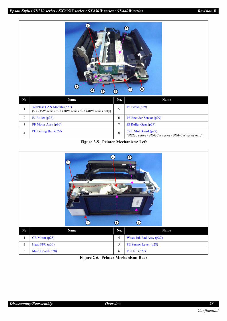
Figure 2-5. Printer Mechanism: Left
Figure 2-6. Printer Mechanism: Rear
No. Name No. Name
1 Wireless LAN Module (p27) (SX235W series / SX430W series / SX440W series only) 5 PF Scale (p29)
2 EJ Roller (p27) 6 PF Encoder Sensor (p29)
3 PF Motor Assy (p30) 7 EJ Roller Gear (p27)
4 PF Timing Belt (p29) 8 Card Slot Board (p27) (SX230 series / SX430W series / SX440W series only)
No. Name No. Name
1 CR Motor (p28) 4 Waste Ink Pad Assy (p27)
2 Head FFC (p30) 5 PE Sensor Lever (p28)
3 Main Board (p28) 6 PS Unit (p27)
3
12
7 84 5 6
1
2 3
4 5 6
Confidential
ssembly/Reassembly Overview 23

Disa
Epson Stylus SX230 series / SX235W series / SX430W series / SX440W series Revision B
2.1.4 Standard Operation Time for Servicing the ProductThe following are the standard operation time for servicing the product. This standard operation time was determined with the MTTR result measured using the prototype of SX430W series which have the most functions. For other models described in this manual, perform the repair work referring to this standard operation time though the time varies due to the structural difference between models.
The underlined parts/units are supplied as After Service Parts.
Table 2-1. Standard Operation Time
Parts/UnitTime (mm:ss)
Replacement Adjustment/inspection Total
Housing rear 0:36 --- 0:36
Paper Support Assy 0:12 --- 0:12
Tray Front Assy 0:13 2:32 2:45
Document Cover 0:10 --- 0:10
Document Mat 0:23 --- 0:23
Star Wheel Holder Assy 0:33 4:10 4:43
Paper Guide Front Unit 0:37 8:47 9:24
Paper Guide Lower Porous Pad 0:46 0:16 1:02
FFC Cover Outer 0:10 --- 0:10
Holder Board Assy 1:11 --- 1:11
FFC Cover Inner 0:12 --- 0:12
Print Head 2:49 14:40 17:29
Waste Ink Pad Assy 0:29 0:16 0:45
Paper Back Lever 1:39 --- 1:39
Retard Roller Assy 1:47 0:44 2:31
Scanner Unit 1:33 2:07 3:40
Scanner Housing Upper 3:04 --- 3:04
CIS Module Unit 3:25 --- 3:25
CIS Module 3:38 --- 3:38
Spacer 3:38 --- 3:38
Scanner Carriage Unit 3:50 --- 3:50
Scanner Carriage 4:45 --- 4:45
Scanner Motor 7:02 2:07 9:09
CIS Holder Unit 7:02 --- 7:02
Scanner Housing Lower 3:50 --- 3:50
Housing Left 2:31 --- 2:31
PS Unit 3:00 0:58 3:58
Card Slot Board 3:27 --- 3:27
Wireless LAN Module 3:17 --- 3:17
PF Encoder Sensor 3:07 --- 3:07
PF Scale 3:22 --- 3:22
PF Driven Pulley Assy 3:57 1:00 4:57
PF Timing Belt 4:09 1:00 5:09
Confidential
ssembly/Reassembly Overview 24

Disa
Epson Stylus SX230 series / SX235W series / SX430W series / SX440W series Revision B
EJ Roller Gear 2:45 --- 2:45
EJ Roller 3:27 4:10 7:37
Hinge 1:49 --- 1:49
Housing Right 2:03 --- 2:03
Cap Assy 3:03 --- 3:03
Cap Lever 3:19 --- 3:19
Porous Pad for Cap Assy 3:10 --- 3:10
Panel Unit 4:19 --- 4:19
Panel Housing Lower Assy 5:12 --- 5:12
Panel Board Assy 5:41 --- 5:41
Panel Board 5:44 --- 5:44
LCD 5:48 --- 5:48
Panel Buttons 6:18 --- 6:18
Panel Housing Upper Assy 6:18 --- 6:18
CR Scale 3:53 --- 3:53
Hopper 3:53 5:28 9:21
LD Roller Cover 3:50 --- 3:50
LD Roller Assy 4:24 0:44 5:08
FFC Holder MB 4:17 --- 4:17
Shield Plate 7:04 --- 7:04
CR Motor 7:52 0:31 8:23
PE Sensor Lever 8:34 0:44 9:18
Main BoardEEPROM Data copy OK 7:45 1:29 9:14
EEPROM Data copy NG 7:45 16:37 24:22
CR Driven Pulley 3:44 1:00 4:44
Main Frame Assy 8:02 12:35 20:37
Paper Guide Upper Assy 14:08 8:31 22:39
CR Unit 12:47 9:47 22:34
CR Timing Belt 13:01 1:00 14:01
CR Encoder Sensor 13:08 --- 13:08
FFC Holder 13:15 --- 13:15
Head FFC 13:15 --- 13:15
Frame Base Assy 8:02 10:38 18:40
Pump Unit 9:48 --- 9:48
PF Grounding Spring 9:56 --- 9:56
Spur Gear 16.5 9:58 --- 9:58
PF Roller Unit 10:30 6:10 16:40
PF Motor Assy 11:10 1:27 12:37
Frame Base 11:10 7:28 18:38
Table 2-1. Standard Operation Time
Parts/UnitTime (mm:ss)
Replacement Adjustment/inspection Total
Confidential
ssembly/Reassembly Overview 25
Disa
Epson Stylus SX230 series / SX235W series / SX430W series / SX440W series Revision B
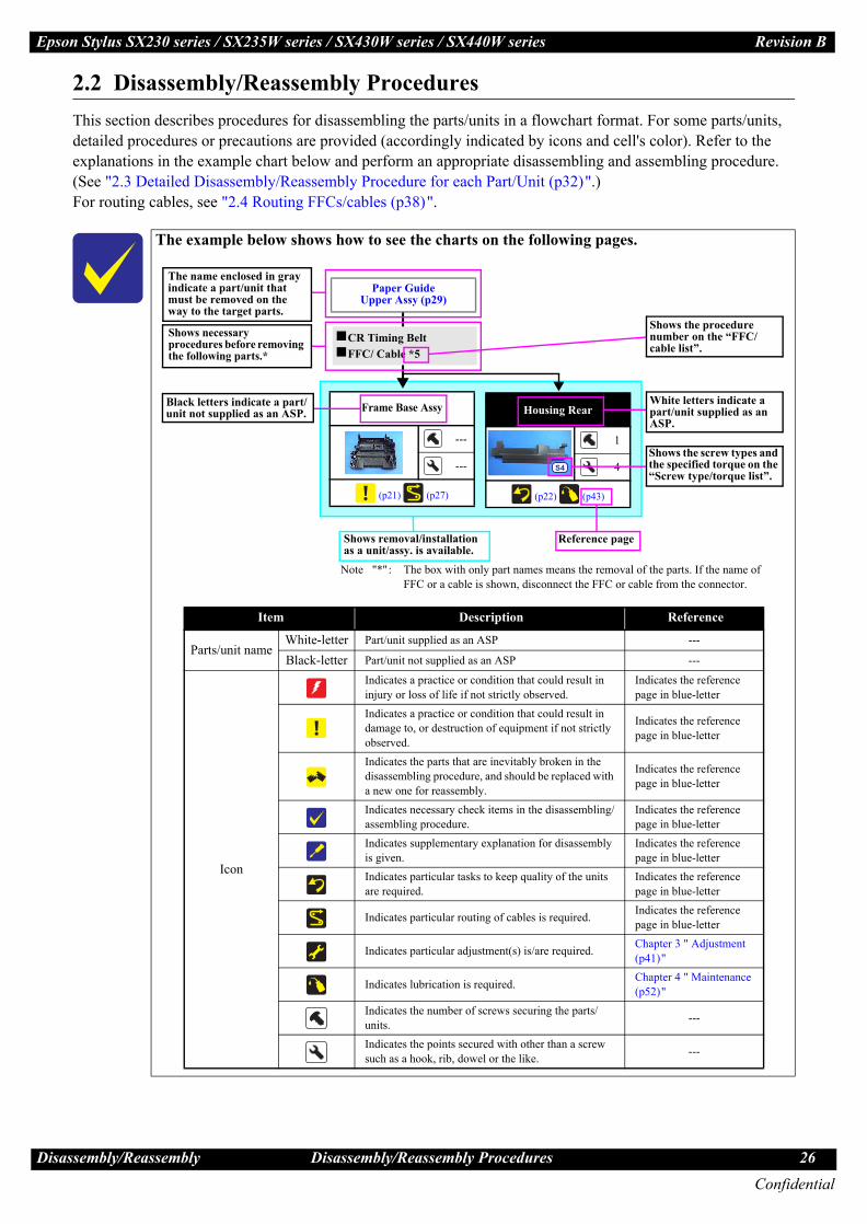
2.2 Disassembly/Reassembly ProceduresThis section describes procedures for disassembling the parts/units in a flowchart format. For some parts/units, detailed procedures or precautions are provided (accordingly indicated by icons and cell's color). Refer to the explanations in the example chart below and perform an appropriate disassembling and assembling procedure. (See "2.3 Detailed Disassembly/Reassembly Procedure for each Part/Unit (p32)".)For routing cables, see "2.4 Routing FFCs/cables (p38)".
The example below shows how to see the charts on the following pages.
Housing Rear
1
4
(p22) (p43)
S4
Frame Base Assy
---
---
(p21) (p27)
Paper Guide Upper Assy (p29)
CR Timing BeltFFC/ Cable *5
Shows necessary procedures before removing the following parts.*
Black letters indicate a part/unit not supplied as an ASP.
Item Description Reference
Parts/unit nameWhite-letter Part/unit supplied as an ASP ---
Black-letter Part/unit not supplied as an ASP ---
Icon
Indicates a practice or condition that could result in injury or loss of life if not strictly observed.
Indicates the reference page in blue-letter
Indicates a practice or condition that could result in damage to, or destruction of equipment if not strictly observed.
Indicates the reference page in blue-letter
Indicates the parts that are inevitably broken in the disassembling procedure, and should be replaced with a new one for reassembly.
Indicates the reference page in blue-letter
Indicates necessary check items in the disassembling/assembling procedure.
Indicates the reference page in blue-letter
Indicates supplementary explanation for disassembly is given.
Indicates the reference page in blue-letter
Indicates particular tasks to keep quality of the units are required.
Indicates the reference page in blue-letter
Indicates particular routing of cables is required. Indicates the reference page in blue-letter
Indicates particular adjustment(s) is/are required. Chapter 3 " Adjustment (p41)"
Indicates lubrication is required. Chapter 4 " Maintenance (p52)"
Indicates the number of screws securing the parts/units. ---
Indicates the points secured with other than a screw such as a hook, rib, dowel or the like. ---
White letters indicate a part/unit supplied as an ASP.
Shows the screw types and the specified torque on the “Screw type/torque list”.
Reference pageShows removal/installation as a unit/assy. is available.
The name enclosed in gray indicate a part/unit that must be removed on the way to the target parts.
Note "*": The box with only part names means the removal of the parts. If the name of FFC or a cable is shown, disconnect the FFC or cable from the connector.
Shows the procedure number on the “FFC/cable list”.
Confidential
ssembly/Reassembly Disassembly/Reassembly Procedures 26

Eps s SX230 series / SX235W series / SX430W series / SX440W series Revision B
ConfidentialDisa y/Reassembly Disassembly Flowchart 27
2.2. assembly Flowchart
Flowchart 2-1. Disassembly Flowchart (1)
ART
A
ng Rear
1
4
(p 32)
S4
Document Cover
---
2
---
1
Paper Support Assy
---
2
---
(p 28)
(p 29)
Screw type/torque list
Symbol Screw Type Torque
C.B.P-TITE SCREW 2.5x8 F/ZN-3C 3 ± 1 kgf·cm
C.B.P-TITE SCREW 2x8 F/ZN-3C 4 ± 1 kgf·cm
C.B.P-TITE SCREW 3x10 F/ZN-3C 5 ± 1 kgf·cm
C.B.P-TITE SCREW 3x10 F/ZN-3C 6 ± 1 kgf·cm
C.B.S-TITE SCREW 3x6 F/ZN-3C 4 ± 0.5 kgf·cm
C.B.S-TITE SCREW 3x6 F/ZN-3C 6 ± 1 kgf·cm
C.B.S-TITE SCREW 3x8 F/ZN-3C 6 ± 1 kgf·cm
C.P SCREW 3x4 F/ZN-3C 4 ± 1 kgf·cm
C.P.F.B-TITE SCREW 2x8 F/ZN-3C 4 ± 1 kgf·cm
C.P.S-TITE (P2) SCREW 3x6 F/ZN-3C 7 ± 1 kgf·cm
S1
S2
S3
S4
S5
S6
S7
S8
S9
S10
Common parts/unit
r Guide Porous ad
---
1
) (p 41)
Star Wheel Holder Assy
2
2
(p 35) (p 41)
S4
e (p27)
ng Right 27)
er Unit
1
2
(p 41)
S4
ing Left
1
5
(p 32)
S4
Tray Front Assy
---
4
(p 41)
r Guide t Unit
2
2
(p 34, p 35)
(p 41)
S4
Waste Ink Pad Assy
1
2
(p 32) (p 41)
S4
Paper Back Lever
---
2
(p 52)
Retard Roller Assy
---
2
(p 41)
FFC Cover Outer
---
1
(p 37)
Holder Board Assy
---
2
---
FFC Cover Inner
---
2
(p 37)
Printhead
3
---
(p 36) (p 41)
S1
inge
1
---
---
S4
ng Right
---
3
(p 32)
Assy
---
3
(p 35)
Wireless LAN Module
2
---
(p 37)
S5
Lever
---
---
(p 35)
PS Unit
---
2
(p 32) (p 40)
(p 41)
EJ Roller Gear
---
---
(p 34) (p 52)
Card Slot Board
2
---
(p 39)
S4
EJ Roller
---
6
(p 41) (p 52)
Porous Pad for Cap Assy
---
---
---
S FC (CN11)F re
Cable (CN501) Cable (CN9)
Spring (×2)e
CSIC FFC Extension Spring (x2)
Star Wheel Holder Assy
(p27)
2 (p 29)
The following parts can be replaced without removing the Scanner Unit. However, the working space for replacement is narrow and dark. Therefore, if you find it difficult to work, remove the Scanner Unit first before replacement.
Printhead/Holder Board AssyStar Wheel Holder AssyPaper Guide Front Unit/Paper Guide Lower Porous Pad
Document Mat
---
---
(p 32)
SX430W series/SX230 series/SX440W series specific parts/unit
SX430W series/SX235W series/SX440W series specific parts/unit
FFC Cover Inner (p27)
FFC Holder
---
1
(p 39)
on Stylu
ssembl
1 Dis
ST
Housi
Hing
Housi(p
Scann
Hous
canner Ferrite co
PapeLower
P
(p 35
PapeFron
H
Housi
Cap
Cap
Extension Pump Tub
Eps us SX230 series / SX235W series / SX430W series / SX440W series Revision B
ConfidentialDisa ly/Reassembly Disassembly Flowchart 28
Panel Housing Lower Assy
3
4
(p 33) (p 38)
S4
Panel Buttons
---
---
---
Panel Board Assy
---
3
(p 38)
S4
FFC/Cable* 8
Panel Housing Upper Assy
---
---
---
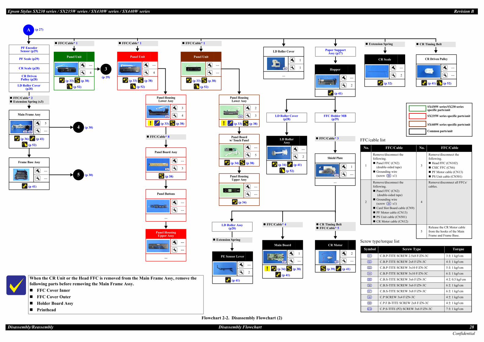
Flowchart 2-2. Disassembly Flowchart (2)
Panel Unit
---
4
(p 33) (p 38)
(p 52)
CR Scale
---
2
(p 32)
LD Roller Cover
1
1
---
S4
LD RollerAssy
---
2
(p 34) (p 41)
(p 52)
rame Assy
5
---
) (p 41)
(p 52)
S6
Base Assy
---
---
(p 41)
CR Driven Pulley
---
---
(p 41) (p 52)
A
4 (p 30)
Screw type/torque list
Symbol Screw Type Torque
C.B.P-TITE SCREW 2.5x8 F/ZN-3C 3 ± 1 kgf·cm
C.B.P-TITE SCREW 2x8 F/ZN-3C 4 ± 1 kgf·cm
C.B.P-TITE SCREW 3x10 F/ZN-3C 5 ± 1 kgf·cm
C.B.P-TITE SCREW 3x10 F/ZN-3C 6 ± 1 kgf·cm
C.B.S-TITE SCREW 3x6 F/ZN-3C 4 ± 0.5 kgf·cm
C.B.S-TITE SCREW 3x6 F/ZN-3C 6 ± 1 kgf·cm
C.B.S-TITE SCREW 3x8 F/ZN-3C 6 ± 1 kgf·cm
C.P SCREW 3x4 F/ZN-3C 4 ± 1 kgf·cm
C.P.F.B-TITE SCREW 2x8 F/ZN-3C 4 ± 1 kgf·cm
C.P.S-TITE (P2) SCREW 3x6 F/ZN-3C 7 ± 1 kgf·cm
S1
S2
S3
S4
S5
S6
S7
S8
S9
S10
aper Support Assy (p27)
When the CR Unit or the Head FFC is removed from the Main Frame Assy, remove the following parts before removing the Main Frame Assy.
FFC Cover InnerFFC Cover OuterHolder Board AssyPrinthead
5 (p 30)
Hopper
---
2
(p 41)
Shield Plate
1
---
---
S6
Main Board
1
---
(p 34) (p 38)
(p 41)
S7
CR Motor
2
---
p 39) (p 41)
S8
LD Roller Assy (p28)
PE Sensor Lever
---
2
(p 41)
F e* 2E Spring (x3)
FFC/Cable* 1 Extension Spring CR Timing Belt
able* 3
Extension Spring
FFC/Cable* 4 iming Beltable* 5
FFC/cable list
No. FFC/Cable No. FFC/Cable
1
Remove/disconnect the following.
Panel FFC (CN2)(double-sided tape)Grounding wire (screw x1)
3
Remove/disconnect the following.
Head FFC (CN102)CSIC FFC (CN6)PF Motor cable (CN13)PS Unit cable (CN501)
2
Remove/disconnect the following.
Panel FFC (CN2) (double-sided tape)Grounding wire (screw x1)Card Slot Board cable (CN9)PF Motor cable (CN13)PS Unit cable (CN501)CR Motor cable (CN12)
4
Remove/disconnect all FFCs/cables.
5Release the CR Motor cable from the hooks of the Main Frame and Frame Base.
S6
S6
ncoder r (p29)
ale (p29)
ale (p28)
Driven y (p28)
ler Cover 28)
Panel Unit
---
---
(p 33) (p 38)
(p 52)
FFC/Cable* 1
Panel Housing Lower Assy
2
3
(p 33) (p 38)
S4
Panel Board w/ Touch Panel
---
5
(p 34) (p 38)
Panel Housing Upper Assy
---
---
(p 34)
SX440W series specific parts/unit
3(p 29)
FFC/Cable* 1
Panel Unit
---
4
(p 33) (p 38)
(p 52)
SX235W series specific parts/unit
Common parts/unit
SX430W series/SX230 seriesspecific parts/unit
LD Roller Cover (p28)
C Holder MB (p29)
(p 27)
on Styl
ssemb
Main F
(p 36
S4
Frame
FC/Cablxtension
PF ESenso
PF Sc
CR Sc
CR Pulle
LD Rol(p
P
(
FFC/C
CR TFFC/C
FF
Eps us SX230 series / SX235W series / SX430W series / SX440W series Revision B
ConfidentialDisa ly/Reassembly Disassembly Flowchart 29
FFC Holder MB
1
---
---
S7
Panel FFC* 7
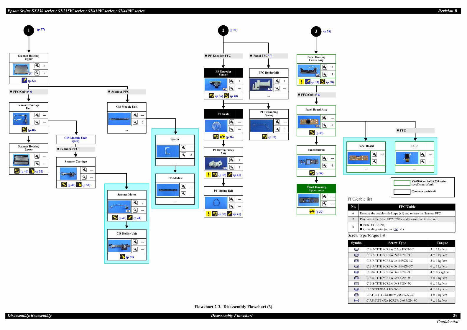
Flowchart 2-3. Disassembly Flowchart (3)
1 (p 27)
ousing r Assy
3
3
3) (p 38)
S4
Screw type/torque list
Symbol Screw Type Torque
C.B.P-TITE SCREW 2.5x8 F/ZN-3C 3 ± 1 kgf·cm
C.B.P-TITE SCREW 2x8 F/ZN-3C 4 ± 1 kgf·cm
C.B.P-TITE SCREW 3x10 F/ZN-3C 5 ± 1 kgf·cm
C.B.P-TITE SCREW 3x10 F/ZN-3C 6 ± 1 kgf·cm
C.B.S-TITE SCREW 3x6 F/ZN-3C 4 ± 0.5 kgf·cm
C.B.S-TITE SCREW 3x6 F/ZN-3C 6 ± 1 kgf·cm
C.B.S-TITE SCREW 3x8 F/ZN-3C 6 ± 1 kgf·cm
C.P SCREW 3x4 F/ZN-3C 4 ± 1 kgf·cm
C.P.F.B-TITE SCREW 2x8 F/ZN-3C 4 ± 1 kgf·cm
C.P.S-TITE (P2) SCREW 3x6 F/ZN-3C 7 ± 1 kgf·cm
S1
S2
S3
S4
S5
S6
S7
S8
S9
S10
uttons
---
4
p 34)
Scanner Motor
2
---
(p 40) (p 41)
S3
ousing r Assy
---
---
p 37)
r Housing pper
4
7
(p 32)
S4
r Housing ower
---
---
) (p 52)
r Carriage Unit
---
---
(p 40)
Spacer
---
2
---
CIS Holder Unit
---
---
(p 52)
CIS Module
---
---
---
Panel Board
---
---
---
LCD
---
---
---
F e* 6
FFC/cable list
No. FFC/Cable
6 Remove the double-sided tape (x1) and release the Scanner FFC.
7 Disconnect the Panel FFC (CN2), and remove the ferrite core.
8Panel FFC (CN1)Grounding wire (screw x1)S4
Scanner FFC
FPC
CIS Module Unit
---
2
---
Scanner Carriage
---
---
(p 40) (p 52)
CIS Module Unit (p29)
2 (p 27)
PF Scale
---
---
(p 36)
PF Timing Belt
---
---
(p 35) (p 41)
PF Encoder Sensor
1
---
(p 36) (p 40)
S2
PF Encoder FFC
PF Driven Pulley Assy
1
1
(p 35) (p 41)
S10
Scanner FFC
ard Assy
---
5
p 38)
S4
F * 8
Common parts/unit
SX430W series/SX230 seriesspecific parts/unit
(p 28)
PF Grounding Spring
---
1
(p 37)
on Styl
ssemb
ScanneU
ScanneL
(p 40
Scanne
FC/Cabl
Panel HLowe
(p 3
Panel B
(
Panel HUppe
(
Panel Bo
(
FC/Cable
3

Eps us SX230 series / SX235W series / SX430W series / SX440W series Revision B
ConfidentialDisa ly/Reassembly Disassembly Flowchart 30
Flowchart 2-4. Disassembly Flowchart (4)
4 5(p 28) (p 28)
Screw type/torque list
Symbol Screw Type Torque
C.B.P-TITE SCREW 2.5x8 F/ZN-3C 3 ± 1 kgf·cm
C.B.P-TITE SCREW 2x8 F/ZN-3C 4 ± 1 kgf·cm
C.B.P-TITE SCREW 3x10 F/ZN-3C 5 ± 1 kgf·cm
C.B.P-TITE SCREW 3x10 F/ZN-3C 6 ± 1 kgf·cm
C.B.S-TITE SCREW 3x6 F/ZN-3C 4 ± 0.5 kgf·cm
C.B.S-TITE SCREW 3x6 F/ZN-3C 6 ± 1 kgf·cm
C.B.S-TITE SCREW 3x8 F/ZN-3C 6 ± 1 kgf·cm
C.P SCREW 3x4 F/ZN-3C 4 ± 1 kgf·cm
C.P.F.B-TITE SCREW 2x8 F/ZN-3C 4 ± 1 kgf·cm
C.P.S-TITE (P2) SCREW 3x6 F/ZN-3C 7 ± 1 kgf·cm
S1
S2
S3
S4
S5
S6
S7
S8
S9
S10
r Guide er Assy
---
6
(p 41)
Spur Gear 16.5
---
---
---
n Board p28)
sor Lever p28)
ld Plate p28)
CR Motor (p28)
CR Unit
---
---
(p 39) (p 41)
Head FFC
---
---
(p 39)
CR Timing Belt
---
1
(p 41)
CR Encoder Sensor
1
1
---
S9
Pump Unit
1
1
(p 36)
S4
PF Roller Unit
---
---
(p 41) (p 52)
Frame Base
---
---
(p 41) (p 52)
PF Motor Assy
1
---
(p 40) (p 41)
S4
FFC/cable list
No. FFC/Cable
9Disconnect the CR Encoder FFC.Pull out the Head FFC from the hole of the CR Unit.
FFC/Cable* 9
Pump Tube
Cap Assy (p27)
Paper Guide Front Unit (p27)
EJ Roller Gear (p27)
PF Driven Pulley Assy (p29)
PF Timing Belt (p29)
Antistatic Cloth
1
---
---
S6
FFC Holder (p27)
PF Grounding Spring (p29)
on Styl
ssemb
PapeUpp
Mai(
PE Sen(
Shie(

Eps us SX230 series / SX235W series / SX430W series / SX440W series Revision B
ConfidentialDisa ly/Reassembly Disassembly Flowchart (Printhead/Main Board) 31
2.2. assembly Flowchart (Printhead/Main Board)
Flowchart 2-5. Disassembly Flowchart (Printhead/Main Board)
The Printhead can be replaced without removing the Scanner Unit. However, the working space for replacement is narrow and dark. Therefore, if you find it difficult to work, remove the Scanner Unit first before replacement.
over Outer
---
1
(p 37)
over Inner
---
2
(p 37)
Contact odule
---
2
---
inthead
3
---
36) (p 41)
S1
Housing Rear
1
4
(p 32)
S4
Scanner Unit
1
2
---
S4
Housing Left
1
5
(p 32)
S4
Hinge
1
---
---
S4
Housing Right
---
3
(p 32)
Paper Support Assy
---
2
---
Hopper
---
2
(p 41)
Shield Plate
---
S6
Main Board
(p 34) (
(p 41)
S7
C C Scanner FFC (CN11)Ferrite core
FFC/Cable* 11
FFC/Cable* 12
FFC/cable list
No. FFC/Cable
10 Disconnect the Panel FFC (CN2), and remove the ferrite core.
11
Remove/disconnect the following.FFC (CN102, CN6)PF Motor cable (CN13)PS Unit cable (CN501)
12 Remove/disconnect all FFCs/cables.
ART
P ad
START
Main Board
FFC/Cable* 10
FFC Holder MB
1
---
---
S7
Screw type/torque list
Symbol Screw Type Torque
C.B.P-TITE SCREW 2.5x8 F/ZN-3C 3 ± 1 kgf·cm
C.B.P-TITE SCREW 2x8 F/ZN-3C 4 ± 1 kgf·cm
C.B.P-TITE SCREW 3x10 F/ZN-3C 5 ± 1 kgf·cm
C.B.P-TITE SCREW 3x10 F/ZN-3C 6 ± 1 kgf·cm
C.B.S-TITE SCREW 3x6 F/ZN-3C 4 ± 0.5 kgf·cm
C.B.S-TITE SCREW 3x6 F/ZN-3C 6 ± 1 kgf·cm
C.B.S-TITE SCREW 3x8 F/ZN-3C 6 ± 1 kgf·cm
C.P SCREW 3x4 F/ZN-3C 4 ± 1 kgf·cm
C.P.F.B-TITE SCREW 2x8 F/ZN-3C 4 ± 1 kgf·cm
C.P.S-TITE (P2) SCREW 3x6 F/ZN-3C 7 ± 1 kgf·cm
S1
S2
S3
S4
S5
S6
S7
S8
S9
S10
on Styl
ssemb
2 Dis
FFC C
FFC C
CRM
Pr
(p
SIC FF
ST
rinthe
1
---
1
---
p 38)

Eps Revision B
Disa 32Confidential
2.3
ReAliMa
Housing Rear
e procedure below.ear.
and release the dowels (x2) of the Housing Left from the Housing Rear, and lift the rear side of the on B from the Housing Left.g Rear slightly to the front to release it from the gap between the Housing Right and Frame Base.f the arrow to release the section D, and remove the Housing Rear while avoiding the Hopper and
C.B.P-TITE SCREW 3x10 F/ZN-3C (6 ± 1 kgf·cm)
Section C
Step 3-4
Ink Position Label
Section D
Step 1
Housing Rear DowelRib
Housing Right
Left
Base when widen the
edure below., widen the rib of the Unit.e in the direction of S Unit.nnector on the PS
HookRib
Waste Ink Pad Assy
When installing the Waste Ink Pad Assy, follow the procedure below.1. Place the Waste Ink Pad Assy under the Frame Base.2. Slide the Waste Ink Pad Assy in the direction of the arrow to
align the hole of the Waste Ink Pad Assy with the hook of the Frame Base.
3. Confirm the following first, and then tighten the screw to secure the Waste Ink Pad Assy.
• The rib of the Waste Ink Pad Assy is correctly inserted into the hole of the Frame Base.
• The Waste Ink Pad Assy is secured firmly with the hook of the Frame Base.
C.B.P-TITE SCREW 3x10 F/ZN-3C (6 ± 1 kgf·cm)
Hook and holeFrame Base
Waste Ink Pad Assy Bottom
Waste Ink Pad Assy
Rear
Rib and hole
ssembly/Reassembly
Attach the CR Scale to the hook on the left of the Main Frame with the black triangle mark upward.Make sure to put the CR Scale through the slit of the CR Encoder Sensor.
CR Unit
Slit of CR Encoder Sensor
When releasing the hbe careful not to dam
Release the hooks shHousing Right.
C.B.P-
Housing Left
on Stylus SX230 series / SX235W series / SX430W series / SX440W series
Detailed Disassembly/Reassembly Procedure for each PDocument Mat
When attaching the Document Mat to the Document Cover, follow the procedure below.1. Attach double-sided tape on the two long sides of the
Document Mat.2. Place the mat on the document glass with double-sided tape
attachment side upward while aligning it with the reference position of the document glass shown above.
3. Close the Document Cover and press the cover to stick the Document Mat to the Document Cover.
Document Mat
Document Cover
Reference (origin) position Double-sided tape
ference position:gn the Document Mat with the front right corner of the document glass.ke sure the gap in yellow above must be less than 1 mm.
Scanne
When removing the Housing Lower Assy1. Remove the scre2. Release the ribs
remove the Scanarrow with the d
C.B
Scanner Housing Upper
CR Scale
Black triangle mark
CR Scale
Extension spring
Housing
Detailed Disassembly/Reassembly Procedure for each Part/Unit
ooks (x7) of the Housing Left/Housing Right, age the hooks (x7).
own above when removing the Housing Left/
TITE SCREW 3x10 F/ZN-3C (6 ± 1 kg·fcm)
Housing Right
Be careful not to damage the rib of the Framerib to release the hook of the PS Unit.
When removing the PS Unit, follow the proc1. Using a precision screwdriver or the like
Frame Base to release the hook of the PS2. Remove the PS Unit from the Frame Bas
the arrow while releasing the rib of the P3. Disconnect the PS Unit cable from the co
Unit and remove the PS Unit.
PS Unit
Widen this rib to release the hook of PS Unit.
art/Unitr Housing Upper
Scanner Housing Upper from the Scanner , follow the procedure below.ws (x4) on the bottom of the Scanner Unit.(x7) of the Scanner Housing Upper, and ner Housing Upper in the direction of the ocument glass upward.
.P-TITE SCREW 3x10 F/ZN-3C (6 ± 1 kgf·cm)
Rib
When removing the Housing Rear, follow th1. Remove the screw (x1) of the Housing R2. Press the section A on the Housing Left
Housing Rear slightly to release the secti3. Pull and turn the section C of the Housin4. Slide the Housing Rear in the direction o
Scanner Unit.
Step 2
Section B
Section A
Housing Rear
The section enclosed in red dotted line may be interfered with the Hopper or the Scanner Unit.
Housing
Left/Housing Right
Hook
PS Unit
Bottom

Eps Revision B
Disa 33Confidential
ing Lower Assy (SX230 series/SX430W series)
e Panel Housing Upper Assy when releasing them.
ssy, follow the procedure below.he Panel Unit.lightly to release the hook of the Panel Housing Lower Assy.ing Upper Assy one by one, and remove the Panel Housing Lower Assy.
C.B.P-TITE SCREW 3x10 F/ZN-3C (6 ± 1 kgf·cm)
Back
Panel Unit
I
P
l Housing Lower Assy (SX440W series)
e Panel Housing Upper Assy when releasing them.
ssy, follow the procedure below.he Panel Unit.lightly to release the hook of the Panel Housing Lower Assy.ing Upper Assy one by one, and remove the Panel Housing Lower Assy.
C.B.P-TITE SCREW 3x10 F/ZN-3C (6 ± 1 kgf·cm)
Back
Panel Unit
ssembly/Reassembly
Be careful not to damage the hooks (x2) of the Panel Housing Upper Assy when releasing them.
When removing the Panel Housing Lower Assy, follow the procedure below.1. Remove the screws (x3) on the back of the Panel Unit.2. Widen the upper side of the Panel Unit slightly to release the hooks (x2) of the Panel Housing Lo3. Release the hooks (x2) of the Panel Housing Upper Assy one by one, and remove the Panel Hous
Hook
anel Housing Upper Assy
C.B.
Panel Unit
on Stylus SX230 series / SX235W series / SX430W series / SX440W series
Panel Unit
When installing the Panel Unit, follow the procedure below.1. Route the Panel FFC and grounding wire through the holes of the Frame Base. (p 38)2. Insert the dowels (x2) of the Panel Stand into the grooves on both sides of the Frame Base from the3. Insert the dowels (x2) of the Panel Unit into the holes (x2) of the Frame Base, and secure the Pane
Frame Base (left)
Rail section
Panel UnitPanel Stand
Panel Unit
Panel Housing Lower Assy (SX235W series)
nside Panel UnitPanel Housing
Lower Assy
Back
Detailed Disassembly/Reassembly Procedure for each Part/Unit
wer Assy.ing Lower Assy.
P-TITE SCREW 3x10 F/ZN-3C (6 ± 1 kgf·cm)
Be careful not to damage the hooks (x2) of th
When removing the Panel Housing Lower A1. Remove the screws (x2) on the back of t2. Widen the upper side of the Panel Unit s3. Release the hooks (x2) of the Panel Hous
Hook
Panel Housing Upper Assy
sections indicated in the arrows shown above.l Unit to the Frame Base.
Frame Base (right)
Rail section
HoleDowel
Panel Hous
Be careful not to damage the hooks (x2) of th
When removing the Panel Housing Lower A1. Remove the screws (x3) on the back of t2. Widen the upper side of the Panel Unit s3. Release the hooks (x2) of the Panel Hous
Hook
Inside Panel Unit
Panel Housing Upper Assy
Panel Housing Lower Assy
Pane
Inside Panel UnitPanel Housing
Lower Assy

Eps Revision B
Disa 34Confidential
Pa
dress Label.
r Lever to the rear. re the lever part of the f the PE Sensor.ield Plate on the
Main Board
Paper Guide Front Unit
When installing the Paper Guide Front Unit, align the positioning holes (x2) of the Paper Guide Front Unit with the dowels (x2) of the Frame Base.Tighten the screws in the order indicated in the figure above.
Dowel and positioning hole
C.B.P-TITE SCREW 3x10 F/ZN-3C (6 ± 1 kgf·cm)
Paper Guide Front
1 2
oving the LD Roller the figure above.
nsion Spring
Spur gear
EJ Roller Gear
The rib on the contact point of the EJ Roller Gear with the EJ Roller is deformed when removing the EJ Roller Gear. Therefore, make sure to replace it with a new one when removing it in order to maintain the paper feed accuracy.
EJ Roller GearCan not be reused because the rib of the EJ Roller Gear is deformed once removed from the EJ Roller.
ssembly/Reassembly
Install the LD Roller Assy with the following condition in order to avoid the Change Lever and PaperUsing a screw driver or the like, hold the Paper Back Lever to the rear as shown above not to let iPush the Change Lever to the front to keep it in the hole of the Main Frame.
LD Roller Assy
Paper Back Lever
Cam
on Stylus SX230 series / SX235W series / SX430W series / SX440W series
Panel Buttons (SX230 series/SX430W series)
When attaching the Select Button to the Panel Housing Upper Assy, attach the Select Button with its side without any rib downward.
Select Button (back)
RibNo rib here.
Start button
Stop ButtonSelect ButtonOK ButtonPower Button
Home Button
The side without any rib must be the side of down arrow.
nel Housing Upper Assy
Panel Board w/T
When installing the Assy, insert the PaneHousing Upper AssyHousing Upper AssyUnit.
Panel Board Unit
Dowel and positioning hole
LD Roller Assy (1)
Change LeverRear of printer
Detailed Disassembly/Reassembly Procedure for each Part/Unit
Back Lever.t touch the LD Roller Assy. If each part shown above comes off when rem
Assy, attach them back in place as shown in
LD Roller
LD Roller Shaft
Exte
ouch Panel (SX440W series)
Panel Board Unit to the Panel Housing Upper l Board Unit under the ribs (x3) of the Panel , and then align the dowels (x2) of the Panel with the positioning holes of the Panel Board
Panel Housing Upper Assy Rib
Positioning hole
Dowel
Dowel and positioning hole
Main Board
Do not damage or contaminate the MAC Ad
Install the Main Board with the PE SensoAfter installing the Main Board, make suPE Sensor Lever is aligned with the slit oAttach the MAC Address Label to the Shposition shown above.
MAC Address LabelShield Plate
Position of MAC Address Label
PE Sensor Lever
PE Sensor
Main Frame
LD Roller Assy (2)
Clutch

Eps Revision B
Disa 35Confidential
he figure above.
-3C (6 ± 1 kgf·cm)
1
Paper Guide Lower Porous Pad
When installing the Paper Guide Lower Porous Pad, set it with the cut section to the front right of the printer.Align the cutout of the Paper Guide Lower Porous Pad with the rib of the Frame Base.
Paper Guide Lower Porous Pad
Frame Base
Rib
Cut Section
Cap Lever/Cap Assy
llow the procedure below. and attach one end of the Extension Spring 0.65 to the hook of the Frame Base. joint on the bottom of the Cap Assy. Then, viewing from the side, confirm the marking (10 ± 1 mm by the Cap Slider.h the hole of the Cap Lever to the hole A of the Frame Base.h the cutout of the Frame Base and to the hole B of the Frame Base.hole C of the Frame Base.he other end of the Extension Spring 0.65 to the hook of the Cap Assy. hooks of the Cap Lever and Frame Base.
Cap Lever
Extension Spring 1.329
Cap Assy
Extension Spring 0.65
Hook of Cap Assy
Hook of Frame Base
Step 6
Step 2
Make sure the marking (10 ± 1 mm from the tube end) on the tube cannot be seen when viewed from the side.
Cap Slider
Hook of Frame Base
Hook of Cap Lever
p 7
ssembly/Reassembly
Do not hold the PF Driven Pulley Assy when securing it with the screw in order to prevent applying i
When installing the PF Driven Pulley Assy, follow the procedure below.1. Align the rib of the PF Driven Pulley Assy with the hook of the PF Motor Frame, and install the P2. Attach the Compression Spring 5.07 to the protrusion of the PF Driven Pulley Assy and the dowe3. Attach the PF Timing Belt in the order of the pinion gear of the PF Motor, PF Driven Pulley and C4. Rotate the Combination Gear 29.2,42 clockwise three times to confirm the PF Timing Belt is corr
Pulley Assy with the screw and washer to the PF Motor Frame.
Pinion gear of PF Motor
Rib
Protrusion
PF Timing Belt
on Stylus SX230 series / SX235W series / SX430W series / SX440W series
Paper Guide Front Porous Pad
When installing the Paper Guide Front Porous Pad, make sure to wipe off the grease attached on the P
The Paper Guide Front Porous Pad is not included in the replacement parts when the maintenance erro
After installing the Paper Guide Front Porous Pad, make sure of the following.The entire anti-disconnect hooks on both ends of the legs (x4) of the Paper Guide Porous Pad shothe Paper Guide Front Unit.The tabs (x34) of the Paper Guide Front Porous Pad should be inserted completely into the grooveNo parts of the Paper Guide Porous Pad are wavy or lift over the platen surface of the Paper Guid
Back
Paper Guide Front Unit
OK No tab of the pad sticks out on the frame.
NG A tab of the pad sticks out on the frame.
Paper Guide Front UnitFront
Enlarged figure: a lGuide Front Por
Anti-di
Paper Guide Front Porous Pad
PF Driven Pulley Assy / PF Timing Belt
Hook
PF Motor Frame
Dowel
PF Driven Pulley Assy
Compression Spring 5.07
Combination Ge
PF Driven Pulley Assy
Detailed Disassembly/Reassembly Procedure for each Part/Unit
mproper tension to the PF Timing Belt.
F Driven Pulley Assy.l of the PF Motor Frame.ombination Gear 29.2,42.
ectly attached, and then secure the PF Driven
C.B.S-TITE(P2) SCREW 3x6 F/ZN-3CP.W. 3.4x0.43x7 (7 ± 1 kgf·cm)
When installing the Cap Lever/Cap Assy, fo1. Attach the Cap Lever to the Frame Base,2. Connect the tube of the Pump Unit to the
from the tube end) on the tube is covered3. Insert the shaft A of the Cap Assy throug4. Insert the shaft B of the Cap Assy throug5. Insert the shaft C of the Cap Assy to the 6. Using a “spring hook jig” (p 20), attach t7. Attach the Extension Spring 1.329 to the
Frame Base
Hole A Hole C
Ste
aper Guide Front Unit.
r occurs.
uld come out from the holes on the bottom of
s of the Paper Guide Front Unit.e Front Unit.
Leg
Paper Guide Front Porous Pad
eg of Paper ous Pad
sconnect hooks
Star Wheel Holder Assy
Tighten the screws in the order indicated in t
Star Wheel Holder Assy
C.B.P-TITE SCREW 3x10 F/ZN
2
ar 29.2,42
Shaft BShaft A
Shaft CCap Assy
CutoutHole BCap Lever
Step 1, 3-5

Eps Revision B
Disa 36Confidential
CR
Main Frame Assy
hift the Change Lever back to the rear.ake sure of the following.ith the Main Frame.
sitioning holes and dowels are correctly aligned. is not deformed. in the figure above.
4
Tighten screw while pressing Main Frame in the direction of the arrow.
C.B.P-TITE SCREW 3x10 F/ZN-3C (6 ± 1 kgf·cm)C.B.S-TITE SCREW 3x6 F/ZN-3C (6 ± 1 kgf·cm)
1
2
Main Frame Assy
Change Lever must not interfere with Main Frame.
Rib and groovePositioning hole and dowel
Section A
Pump Unit
rocedure below in order to prevent ink suction failure. of the Frame Base. and route the Pump Tube A through the ribs of the Frame Base with their dashed line facing upward. with the screw (x1). of the Pump Unit and Frame Base, and insert it to the hole of the Frame Base up to the marking
Step 4 Pump Tube B
Marking
8 ± 1 mm
Hole of Frame Base
Pump Unit
Insert Pump Tube B up to the marking (8 ± 1 mm from tube end) to the hole of Frame Base.
C.B.P-TITE SCREW 3x10 F/ZN-3C (6 ± 1 kgf·cm)
Step 3
rame BaseRib
ssembly/Reassembly
Do not reuse the removed PF Scale and make sure to replace it with a new one when removing it.When installing the PF Scale, it is pressed into the PF Roller, therefore, the removed one is deformed.rotate properly and the paper feed accuracy may be reduced.
When installing the PF Scale to the PF Roller, press the PF Scale into the PF Roller vertically.After installing the PF Encoder Sensor, confirm the PF Scale does not touch the PF Encoder Sens
PF Scale PF Roller
PF R
on Stylus SX230 series / SX235W series / SX430W series / SX440W series
Printhead
When removing/replacing the Printhead, be sure the CR Unit is at the “ink cartridge exchange positiomay be deformed by applying force perpendicularly when tightening the screws and it may affect prinThe “ink cartridge exchange position” is also indicated by the Ink Position Label attached on the Houposition of the Ink Position Label.
Tighten the screws of the Printhead in the order indicated in the figure above while pressing the Printh
Bottom of CR Unit
C.B.P
Printhead
Unit (ink cartridge exchange position)
1 2
3
Ink cartridge exchange poon the section A of the StaDo not remove/replace theorder to prevent the Main
Star Wheel Holder Assy
Main Frame
PF Encoder Sensor/ PF Scale
PF Encoder Sensor
Detailed Disassembly/Reassembly Procedure for each Part/Unit
If it is re-installed to the printer, it does not
or.
PF Scale
oller
When installing the Pump Unit, follow the p1. Route the Pump Tube A through the hole2. Install the Pump Unit to the Frame Base,3. Secure the Pump Unit to the Frame Base4. Route the Pump Tube B through the ribs
(8 ± 1 mm from tube end).
Route Pump Tube A through ribs of Frame Base with their dashed line facing upward.
F
n” shown above. Otherwise, the Main Frame t quality.
sing Rear. See Housing Rear (p32) for the
ead in the direction of the arrow.
Protrusion of CR Unit
Section A
Star Wheel Holder Assy
-TITE SCREW 2.5x8 F/ZN-3C (3 ± 1 kgf·cm)
sition: when the protrusion of the CR Unit is r Wheel Holder Assy. Printhead other than under this condition in Frame from being deformed.
Before installing the Main Frame Assy, sWhen installing the Main Frame Assy, m
• The Change Lever must not interfere w• The above shown ribs and grooves, po• The section A of the Main Frame Assy
Tighten the screws in the order indicated
3
5
Align the screw holes of Main Frame and PF Motor Frame.
PF Motor Frame
Main Frame
PF Encoder Sensor Hole of Frame Base
Pump Tube A
Step 1-2
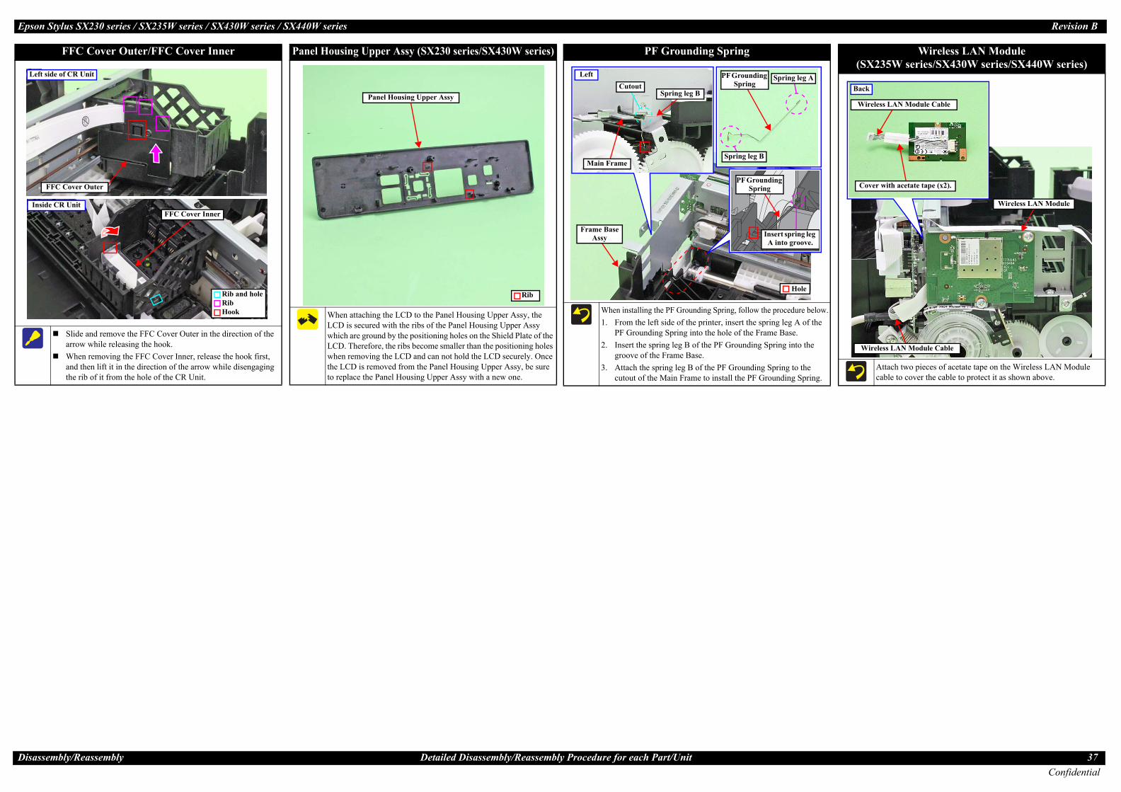
Eps Revision B
Disa 37Confidential
L
I
w the procedure below.e spring leg A of the Frame Base.ng Spring into the
ing Spring to the F Grounding Spring.
Insert spring leg A into groove.
rounding pring
ding g
g B
Spring leg A
Hole
Wireless LAN Module(SX235W series/SX430W series/SX440W series)
Attach two pieces of acetate tape on the Wireless LAN Module cable to cover the cable to protect it as shown above.
Back
Wireless LAN Module Cable
Cover with acetate tape (x2).
Wireless LAN Module
Wireless LAN Module Cable
ssembly/Reassembly
on Stylus SX230 series / SX235W series / SX430W series / SX440W series
FFC Cover Outer/FFC Cover Inner
Slide and remove the FFC Cover Outer in the direction of the arrow while releasing the hook.When removing the FFC Cover Inner, release the hook first, and then lift it in the direction of the arrow while disengaging the rib of it from the hole of the CR Unit.
eft side of CR Unit
FFC Cover Outer
nside CR UnitFFC Cover Inner
Rib and hole
HookRib
Panel Housing Upper A
When attaching the LLCD is secured withwhich are ground byLCD. Therefore, thewhen removing the Lthe LCD is removedto replace the Panel
Panel Ho
Detailed Disassembly/Reassembly Procedure for each Part/Unit
ssy (SX230 series/SX430W series)
CD to the Panel Housing Upper Assy, the the ribs of the Panel Housing Upper Assy the positioning holes on the Shield Plate of the ribs become smaller than the positioning holes CD and can not hold the LCD securely. Once
from the Panel Housing Upper Assy, be sure Housing Upper Assy with a new one.
Rib
using Upper Assy
PF Grounding Spring
When installing the PF Grounding Spring, follo1. From the left side of the printer, insert th
PF Grounding Spring into the hole of the2. Insert the spring leg B of the PF Groundi
groove of the Frame Base.3. Attach the spring leg B of the PF Ground
cutout of the Main Frame to install the P
PF GS
Left
Main Frame
Spring leg BCutout
PF GrounSprin
Spring le
Frame Base Assy

Eps Revision B
Disa 38Confidential
2.4
Conn••••
•
•
H
R
Unit (SX230 series/SX235W series/SX430W series)
Housing Lower Assy with its terminal side upward as shown in the figure above. and then connect the FFC to the connector (CN1) on the Panel Board firmly.the screw, and pull it out from the hole of the Panel Housing Lower Assy.
Panel FFC
ower Assy
Panel FFCPanel Board
nding wire
C.B.P-TITE SCREW 3x10 F/ZN-3C (6 ± 1 kgf·cm)
Panel FFC
Grounding wire(SX230 series/SX430W series only)
Hole of Panel Housing Lower Assy
Pull out grounding wire from here.
Ro
•
•
Bc
e the Panel Unit (SX440W series only)
Housing Lower Assy with its side with the stiffener upward as shown in the figure above.and attach acetate tape as shown above, and then connect the FFC to the connector (CN1) on the Panel
the screw, and pull it out from the hole of the Panel Housing Lower Assy.
Panel FFC
Grounding wire
Hole of Panel Housing Lower Assy
Pull out grounding wire from here.
el FFC
wer Assy
Acetate tape
Grounding wire
C.B.S-TITE SCREW 3x6 F/ZN-3C (6 ± 1 kgf·cm)
ssembly/Reassembly
oute the Panel FFC and grounding wire (SX230 series / SX430W series nly) as follows before installing the Panel Unit.Route the Panel FFC through the hole of the Frame Base as shown above with the side with the stiffener upward.Pull out the grounding wire from the hole of the Frame Base shown above. (SX230 series / SX430W series only)
efore installing the Panel Unit, make sure that the Panel FFC is routed orrectly without any part getting caught.
Hole
Frame Base Panel FFC
Grounding wire(SX230 series / SX430W series only)
After installing the Panel Unit, out from the hole of the Frame
Route Panel FFC through thwith folded along the fold lon the position shown in thRoute the grounding wire thit to the Main Frame with th
Ho
C.B
Panel FFC
on Stylus SX230 series / SX235W series / SX430W series / SX440W series
Routing FFCs/cablesMain Board
ect the following cables/FFCs to the Main Board as shown in the figure above.CSIC FFC (CN6) • Head FFC (CN102) • CR Motor cable (PF Motor cable (CN13) • PS Unit cable (CN501) • PF Encoder FFC Wireless LAN Module cable (CN4: SX235W series/SX430W series only)Panel FFC (CN2)Attach the ferrite core A to the FFC Holder MB, and route the FFC through the ferrite core A and connectScanner FFC (CN11)Attach the ferrite core B to the FFC Holder MB, and route the FFC through the hole of the Housing Left and the ferCard Slot Board cable (CN9:SX230 series/SX430W series only)
Ferrite core AFerrite core B
Panel
PF Motor cable
PS Unit cable
Card Slot Board cable
CR Motor cable
Main Board
CN12
CN6CN102
ead FFC
CSIC FFC
ight side of Main Board
Wireless LANModule cable
PF Encode
FFC Holder MB
Panel Unit (1)
Panel Stand
Panel FFC
Hole for grounding wire
Hole for Panel FFC
P
Panel FFC
Hole
Grounding wire(SX230 series / SX430W ser
Routing FFCs/cables
route the Panel FFC and grounding wire pulled Base as follows.e ribs (x2) of the Frame Base and Main Frame
ine, and then secure it with double-sided tape e figure above.rough the hole A of the Frame Base, and secure e screw.(SX230 series / SX430W series only)
RibDouble-sided tapeGrounding wirele A
.S-TITE SCREW 3x6 F/ZN-3C (6 ± 1 kgf·cm)
Route the Panel FFC through the hole of the Panel Fold the Panel FFC aligning it with its folded lines Board firmly.Secure the grounding wire to the Panel Board with
Panel Housing Lo
CN12)(CN7)
it to the Main Board.
rite core B, and then connect it to the Main Board.
FFC
r FFC
CN11
CN2
CN9
CN4
CN7
CN13
CN501
Left side of Main Board
Housing Left
Route Scanner FFC through Hole of Housing Left.
Inside the Panel
Route the Panel FFC through the hole of the Panel Fold the Panel FFC aligning it with its folded lines,Secure the grounding wire to the Panel Board with (SX230 series/SX430W series only)
Panel Board
Panel Housing L
SX235W series
Panel Housing Lower Assy
SX230 series/SX430W series
Grou
anel Unit (2)
Frame Base Panel Unit
Frame Base
Panel Unit
A
ies only)
Insid
Pan
Panel Board Unit

Eps Revision B
Disa 39Confidential
WRC
Head FFC (1)
m through the FFC Holder as shown in the figure above.
C over the CSIC ead FFC on top.
older RearFFC Holder
Head FFC/CSIC FFC
Main Frame
RHB
C
Le
CR Motor
he Shield Plate. of the Frame Base (two turns).f the Frame Base, and then route it through the rib A taking care not to let the CR Motor cable (red)
ble (red) twice, and then route them through the hook C of the Main Frame.ble (red) in the order of hook D of the Main Frame, groove of the FFC Holder, and hook E of the Main
CR Motor
Hook EGroove of FFC Holdertor cable Hook D
Rib B
ssembly/Reassembly
oute the Head FFC and CSIC FFC through the CR Unit as shown in the figure above, and then connect theolder Board Assy.e careful not to damage the Head FFC when routing it through the hole of the CR Unit.
Head FF
CSIC FFC Head FFC
CR Unit
onnector of CR Contact Module
Hole of CR Unit
on Stylus SX230 series / SX235W series / SX430W series / SX440W series
Card Slot Board (SX230 series/SX430W series/SX440W
hen routing the Card Slot Board cable, be careful not to damage the PF Scale.oute the Card Slot Board cable through the ribs (x4) of the Frame Base.onnect the connectors on both ends of the Card Slot Board cable to the Card Slot Board (CN3) and Main B
Frame Base
Main Board
PF Scale
C
Card Slot Board cable
Head FFC (2)
Inside CR Un
Connector of CR EncoderPut Head FFC over CSIC FFC
ft side of CR Unit
Routing FFCs/cables
m to the Printhead, CR Encoder Sensor and
C Connector of Printhead
Route the CR Motor cable as follows before installing t1. Route the CR Motor cable (black) around the rib A2. Route the CR Motor cable (red) through the rib B o
come over the CR Motor cable (black).3. Twist the CR Motor cable (black) and CR Motor ca4. Route the CR Motor cable (black) and CR Motor ca
Frame.
Rib A
CR Motor cable (black)
series)
oard (CN9) firmly. (p 38)
Rib
Card Slot Board
ard Slot Board cable
CN3
Align the Head FFC and CSIC FFC, and then route the
Aligning Head FFC with CSIC FFC
Head FFC
CSIC FFCStack the Head FFFFC to keep the H
Fold here inside FFC H
FFC Holder
Head FFC/CSIC FFC
PrintheaditHook C
CR Mo
CR Motor cable (red)

Eps Revision B
Disa 40Confidential
RS
Scanner FFC
ner Housing Lower in the direction shown above, and then secure the FFC with double-sided tape on
Housing Lower taking care not to damage the FFC.of the Scanner Carriage taking care not to damage the FFC.IS Module as shown above.
HoleScanner FFC
Scanner Carriage
RibDouble-sided tape
ProP
Main Frame and nd then secure it with ure above.
Encoder FFC
PF Encoder Sensor
Double Side Tape
ssembly/Reassembly
ull out the PS Unit cable from the hole of the Frame Base first, and then ute it through the rib of the Frame Base.
ut the ferrite core into the position shown in the figure above.
HoleRib
PS Unit cable
Bottom of Frame Base
PS Unit cable
Ferrite core
Route the PF Motor cable as fo1. Pull out the PF Motor cable2. Install the PF Motor, and se
the Frame Base, and then r
Bottom of Frame Base
on Stylus SX230 series / SX235W series / SX430W series / SX440W series
Scanner Motor
oute the Scanner Motor cable through the hooks (x4) of the Scanner Motor as shown above.ecure the grounding wire of the Relay Board and the Scanner Motor together with the screw as show above
Relay Board
Scanner Motor cable
C.B.
Scann
Scanner Carriage
PS Unit
Frame Base PFFrame Base
Routing FFCs/cables
llows. from the hole of the Frame Base.cure the PF Motor cable (black) with the rib of
oute it through the rib of the Frame Base.
PF Motor
Route PF Motor cable through rib.
Secure PF Motor cable (black) with rib.
HoleRib
Route the PF Encoder FFC through the ribs (x2) of the connect it to the connector (CN7) on the Main Board, adouble-sided tape (x2) on the positions shown in the fig
PFCN7
Ribs
.
P-TITE SCREW 3x10 F/ZN-3C (5 ± 1 kgf·cm)
Grounding wire Scanner Motor
Screw it with grounding terminal
er Motor
Route the Scanner FFC as follows.1. Insert the Scanner FFC through the hole of the Scan
position shown in the figure above.2. Route the FFC through the ribs (x7) of the Scanner3. Route the FFC through the ribs (x5) on the bottom 4. Connect the Scanner FFC to the Relay Board and C
Bottom of Scanner Carriage
Connector of Relay Board
Connector of CIS Module
PF Motor
Motor cable
PF Encoder Sensor
Left side of printer
Rib

CHAPTER
3ADJUSTMENT
Confidential

Adj
Epson Stylus SX230 series / SX235W series / SX430W series / SX440W series Revision B
3.1 Required AdjustmentsThe table from the following page lists the required adjustments depending upon the parts being repaired or replaced. Find the part(s) you removed or replaced, and check which adjustment(s) must be carried out.
If the EEPROM data cannot be read out from the old Main Board using the Adjustment Program when replacing the Main Board is required, the Waste Ink Pad Assy must be replaced with the Main Board at the same time.After all required adjustments are completed, use the “Final check pattern print” function to print all adjustment patterns for final check. If you find a problem with the printout patterns, carry out the adjustment again.When replacing the Main Board, the adjustment should be made after performing the initial setting.
In this chapter, the product names are called as follows:• SX230 series: Epson Stylus TX235/Epson Stylus SX230/Epson ME OFFICE 535• SX235W series: Epson Stylus NX230/Epson Stylus TX235W/Epson Stylus SX235W/
Epson Stylus TX230W• SX430W series: Epson Stylus NX330/Epson Stylus TX430W/Epson Stylus SX430W/
Epson Stylus SX435W/Epson ME OFFICE 570W• SX440W series: Epson Stylus NX430/Epson Stylus TX435W/
Epson Stylus SX440W/Epson Stylus SX445WThe table items and marks used in the “Required Adjustment List” provided on the following pages have the following meanings.• “O” indicates that the adjustment must be carried out.• “---” indicates that the adjustment is not required.• The “Mechanism Adjustment” should be performed just after reinstalling or
reassembling the part or unit.• The “Adjustments using the Adjustment Program” need to be performed after
reassembling the printer completely.If you have removed or replaced multiple parts, make sure to check the required adjustments for the all parts. And when multiple adjustments must be carried out, be sure to carry out them in the order given in the “Priority” row.
ustment Required Adjustments 42
Confidential
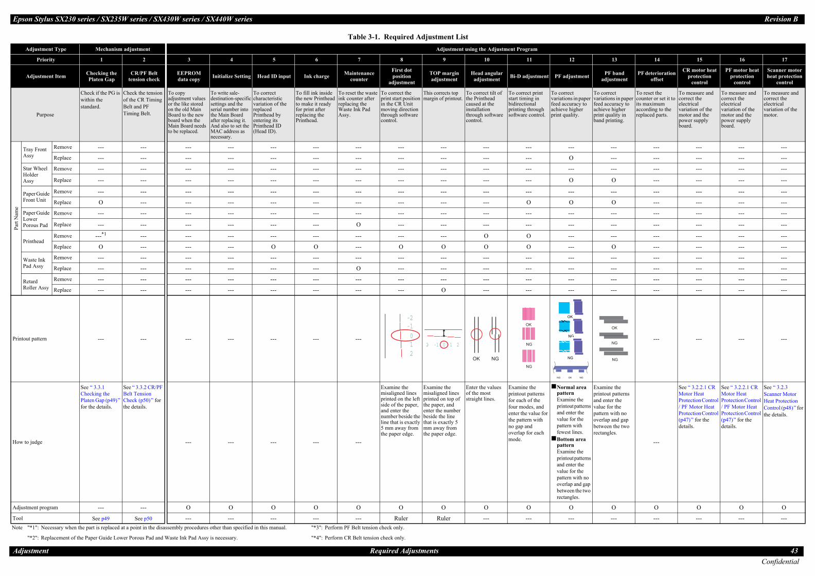
Eps Revision B
Adju 43Confidential
12 13 14 15 16 17
PF adjustment PF band adjustment
PF deterioration offset
CR motor heat protection
control
PF motor heat protection
control
Scanner motor heat protection
control
o correct ariations in paper eed accuracy to chieve higher rint quality.
To correct variations in paper feed accuracy to achieve higher print quality in band printing.
To reset the counter or set it to its maximum according to the replaced parts.
To measure and correct the electrical variation of the motor and the power supply board.
To measure and correct the electrical variation of the motor and the power supply board.
To measure and correct the electrical variation of the motor.
Part
Nam
e
TA
--- --- --- --- --- ---
O --- --- --- --- ---
SHA
--- --- --- --- --- ---
O O --- --- --- ---
PF
--- --- --- --- --- ---
O O --- --- --- ---
PLP
--- --- --- --- --- ---
--- --- --- --- --- ---
P--- --- --- --- --- ---
--- O --- --- --- ---
WP
--- --- --- --- --- ---
--- --- --- --- --- ---
RR
--- --- --- --- --- ---
--- --- --- --- --- ---
Printo --- --- --- ---
How t
Normal area patternExamine the printout patterns and enter the value for the pattern with fewest lines.Bottom area patternExamine the printout patterns and enter the value for the pattern with no overlap and gap between the two rectangles.
Examine the printout patterns and enter the value for the pattern with no overlap and gap between the two rectangles.
---
See “ 3.2.2.1 CR Motor Heat Protection Control / PF Motor Heat Protection Control (p47)” for the details.
See “ 3.2.2.1 CR Motor Heat Protection Control / PF Motor Heat Protection Control (p47)” for the details.
See “ 3.2.3 Scanner Motor Heat Protection Control (p48)” for the details.
Adjus O O O O O O
Tool --- --- --- --- --- ---Note
OK NGNG
OK
NG
NG
OK
NG
NG
on Stylus SX230 series / SX235W series / SX430W series / SX440W series
stment Required Adjustments
Table 3-1. Required Adjustment ListAdjustment Type Mechanism adjustment Adjustment using the Adjustment Program
Priority 1 2 3 4 5 6 7 8 9 10 11
Adjustment Item Checking the Platen Gap
CR/PF Belt tension check
EEPROMdata copy Initialize Setting Head ID input Ink charge Maintenance
counter
First dot position
adjustment
TOP margin adjustment
Head angular adjustment Bi-D adjustment
Purpose
Check if the PG is within the standard.
Check the tension of the CR Timing Belt and PF Timing Belt.
To copy adjustment values or the like stored on the old Main Board to the new board when the Main Board needs to be replaced.
To write sale-destination-specific settings and the serial number into the Main Board after replacing it. And also to set the MAC address as necessary.
To correct characteristic variation of the replaced Printhead by entering its Printhead ID (Head ID).
To fill ink inside the new Printhead to make it ready for print after replacing the Printhead.
To reset the waste ink counter after replacing the Waste Ink Pad Assy.
To correct the print start position in the CR Unit moving direction through software control.
This corrects top margin of printout.
To correct tilt of the Printhead caused at the installation through software control.
To correct print start timing in bidirectional printing through software control.
Tvfap
ray Front ssy
Remove --- --- --- --- --- --- --- --- --- --- ---
Replace --- --- --- --- --- --- --- --- --- --- ---
tar Wheel older ssy
Remove --- --- --- --- --- --- --- --- --- --- ---
Replace --- --- --- --- --- --- --- --- --- --- ---
aper Guide ront Unit
Remove --- --- --- --- --- --- --- --- --- --- ---
Replace O --- --- --- --- --- --- --- --- --- O
aper Guide ower orous Pad
Remove --- --- --- --- --- --- --- --- --- --- ---
Replace --- --- --- --- --- --- O --- --- --- ---
rintheadRemove ---*1 --- --- --- --- --- --- --- --- O O
Replace O --- --- --- O O --- O O O O
aste Ink ad Assy
Remove --- --- --- --- --- --- --- --- --- --- ---
Replace --- --- --- --- --- --- O --- --- --- ---
etard oller Assy
Remove --- --- --- --- --- --- --- --- --- --- ---
Replace --- --- --- --- --- --- --- --- O --- ---
ut pattern --- --- --- --- --- --- ---
o judge
See “ 3.3.1 Checking the Platen Gap (p49)” for the details.
See “ 3.3.2 CR/PF Belt Tension Check (p50)” for the details.
--- --- --- --- ---
Examine the misaligned lines printed on the left side of the paper, and enter the number beside the line that is exactly 5 mm away from the paper edge.
Examine the misaligned lines printed on top of the paper, and enter the number beside the line that is exactly 5 mm away from the paper edge.
Enter the values of the most straight lines.
Examine the printout patterns for each of the four modes, and enter the value for the pattern with no gap and overlap for each mode.
tment program --- --- O O O O O O O O O
See p49 See p50 --- --- --- --- --- Ruler Ruler --- ---"*1": Necessary when the part is replaced at a point in the disassembly procedures other than specified in this manual.
"*2": Replacement of the Paper Guide Lower Porous Pad and Waste Ink Pad Assy is necessary.
"*3": Perform PF Belt tension check only.
"*4": Perform CR Belt tension check only.
-2-1012
-2 -1 0 1 2
NGOK
OK
NG
NG

Eps Revision B
Adju 44Confidential
Part
Nam
e
SU
--- --- --- --- --- ---
--- --- --- --- --- O
SM
--- --- --- --- --- ---
--- --- --- --- --- O
P--- --- --- --- --- ---
--- --- --- O O ---
PP
--- --- --- --- --- ---
--- --- --- --- --- ---
PB
--- --- --- --- --- ---
--- --- --- --- --- ---
E--- --- --- --- --- ---
O O --- --- --- ---
H--- --- --- --- --- ---
--- --- --- --- --- ---
12 13 14 15 16 17
PF adjustment PF band adjustment
PF deterioration offset
CR motor heat protection
control
PF motor heat protection
control
Scanner motor heat protection
control
o correct ariations in paper eed accuracy to chieve higher rint quality.
To correct variations in paper feed accuracy to achieve higher print quality in band printing.
To reset the counter or set it to its maximum according to the replaced parts.
To measure and correct the electrical variation of the motor and the power supply board.
To measure and correct the electrical variation of the motor and the power supply board.
To measure and correct the electrical variation of the motor.
Printo --- --- --- ---
How t
Normal area patternExamine the printout patterns and enter the value for the pattern with fewest lines.Bottom area patternExamine the printout patterns and enter the value for the pattern with no overlap and gap between the two rectangles.
Examine the printout patterns and enter the value for the pattern with no overlap and gap between the two rectangles.
---
See “ 3.2.2.1 CR Motor Heat Protection Control / PF Motor Heat Protection Control (p47)” for the details.
See “ 3.2.2.1 CR Motor Heat Protection Control / PF Motor Heat Protection Control (p47)” for the details.
See “ 3.2.3 Scanner Motor Heat Protection Control (p48)” for the details.
Adjus O O O O O O
Tool --- --- --- --- --- ---Note
OK NGNG
OK
NG
NG
OK
NG
NG
on Stylus SX230 series / SX235W series / SX430W series / SX440W series
stment Required Adjustments
canner nit
Remove --- --- --- --- --- --- --- --- --- --- ---
Replace --- --- --- --- --- --- --- --- --- --- ---
canner otor
Remove --- --- --- --- --- --- --- --- --- --- ---
Replace --- --- --- --- --- --- --- --- --- --- ---
S UnitRemove --- --- --- --- --- --- --- --- --- --- ---
Replace --- --- --- --- --- --- --- --- --- --- ---
F Driven ulley Assy
Remove --- O*3 --- --- --- --- --- --- --- --- ---
Replace --- O*3 --- --- --- --- --- --- --- --- ---
F Timing elt
Remove --- O*3 --- --- --- --- --- --- --- --- ---
Replace --- O*3 --- --- --- --- --- --- --- --- ---
J Roller Remove --- --- --- --- --- --- --- --- --- --- ---
Replace --- --- --- --- --- --- --- --- --- --- ---
opperRemove --- --- --- --- --- --- --- --- --- --- ---
Replace --- --- --- --- --- --- --- O O --- O
Table 3-1. Required Adjustment ListAdjustment Type Mechanism adjustment Adjustment using the Adjustment Program
Priority 1 2 3 4 5 6 7 8 9 10 11
Adjustment Item Checking the Platen Gap
CR/PF Belt tension check
EEPROMdata copy Initialize Setting Head ID input Ink charge Maintenance
counter
First dot position
adjustment
TOP margin adjustment
Head angular adjustment Bi-D adjustment
Purpose
Check if the PG is within the standard.
Check the tension of the CR Timing Belt and PF Timing Belt.
To copy adjustment values or the like stored on the old Main Board to the new board when the Main Board needs to be replaced.
To write sale-destination-specific settings and the serial number into the Main Board after replacing it. And also to set the MAC address as necessary.
To correct characteristic variation of the replaced Printhead by entering its Printhead ID (Head ID).
To fill ink inside the new Printhead to make it ready for print after replacing the Printhead.
To reset the waste ink counter after replacing the Waste Ink Pad Assy.
To correct the print start position in the CR Unit moving direction through software control.
This corrects top margin of printout.
To correct tilt of the Printhead caused at the installation through software control.
To correct print start timing in bidirectional printing through software control.
Tvfap
ut pattern --- --- --- --- --- --- ---
o judge
See “ 3.3.1 Checking the Platen Gap (p49)” for the details.
See “ 3.3.2 CR/PF Belt Tension Check (p50)” for the details.
--- --- --- --- ---
Examine the misaligned lines printed on the left side of the paper, and enter the number beside the line that is exactly 5 mm away from the paper edge.
Examine the misaligned lines printed on top of the paper, and enter the number beside the line that is exactly 5 mm away from the paper edge.
Enter the values of the most straight lines.
Examine the printout patterns for each of the four modes, and enter the value for the pattern with no gap and overlap for each mode.
tment program --- --- O O O O O O O O O
See p49 See p50 --- --- --- --- --- Ruler Ruler --- ---"*1": Necessary when the part is replaced at a point in the disassembly procedures other than specified in this manual.
"*2": Replacement of the Paper Guide Lower Porous Pad and Waste Ink Pad Assy is necessary.
"*3": Perform PF Belt tension check only.
"*4": Perform CR Belt tension check only.
-2-1012
-2 -1 0 1 2
NGOK
OK
NG
NG

Eps Revision B
Adju 45Confidential
Part
Nam
e
LA
--- --- --- --- --- ---
--- --- --- --- --- ---
C--- --- --- --- --- ---
--- --- --- O --- ---
PL
--- --- --- --- --- ---
--- --- --- --- --- ---
M
--- --- --- --- --- ---
--- --- --- --- --- ---
O O O O O ---
CP
--- --- --- --- --- ---
--- --- --- --- --- ---
MA
--- --- --- --- --- ---
O O --- --- --- ---
12 13 14 15 16 17
PF adjustment PF band adjustment
PF deterioration offset
CR motor heat protection
control
PF motor heat protection
control
Scanner motor heat protection
control
o correct ariations in paper eed accuracy to chieve higher rint quality.
To correct variations in paper feed accuracy to achieve higher print quality in band printing.
To reset the counter or set it to its maximum according to the replaced parts.
To measure and correct the electrical variation of the motor and the power supply board.
To measure and correct the electrical variation of the motor and the power supply board.
To measure and correct the electrical variation of the motor.
Printo --- --- --- ---
How t
Normal area patternExamine the printout patterns and enter the value for the pattern with fewest lines.Bottom area patternExamine the printout patterns and enter the value for the pattern with no overlap and gap between the two rectangles.
Examine the printout patterns and enter the value for the pattern with no overlap and gap between the two rectangles.
---
See “ 3.2.2.1 CR Motor Heat Protection Control / PF Motor Heat Protection Control (p47)” for the details.
See “ 3.2.2.1 CR Motor Heat Protection Control / PF Motor Heat Protection Control (p47)” for the details.
See “ 3.2.3 Scanner Motor Heat Protection Control (p48)” for the details.
Adjus O O O O O O
Tool --- --- --- --- --- ---Note
OK NGNG
OK
NG
NG
OK
NG
NG
on Stylus SX230 series / SX235W series / SX430W series / SX440W series
stment Required Adjustments
D Roller ssy
Remove --- --- --- --- --- --- --- --- --- --- ---
Replace --- --- --- --- --- --- --- --- O --- ---
R MotorRemove --- --- --- --- --- --- --- --- --- --- ---
Replace --- --- --- --- --- --- --- --- --- --- ---
E Sensor ever
Remove --- --- --- --- --- --- --- --- --- --- ---
Replace --- --- --- --- --- --- --- --- O --- ---
ain Board
Remove --- --- --- --- --- --- --- --- O --- ---
Replace(Read OK) --- --- O --- --- --- --- --- --- --- ---
Replace(Read NG) --- --- --- O O --- O*2 O O O O
R Driven ulley
--- --- --- --- --- --- --- --- --- --- ---
--- O*4 --- --- --- --- --- --- --- --- ---
ain Frame ssy
Remove --- --- --- --- --- --- --- --- --- --- ---
Replace O O*4 --- --- --- --- --- O --- O O
Table 3-1. Required Adjustment ListAdjustment Type Mechanism adjustment Adjustment using the Adjustment Program
Priority 1 2 3 4 5 6 7 8 9 10 11
Adjustment Item Checking the Platen Gap
CR/PF Belt tension check
EEPROMdata copy Initialize Setting Head ID input Ink charge Maintenance
counter
First dot position
adjustment
TOP margin adjustment
Head angular adjustment Bi-D adjustment
Purpose
Check if the PG is within the standard.
Check the tension of the CR Timing Belt and PF Timing Belt.
To copy adjustment values or the like stored on the old Main Board to the new board when the Main Board needs to be replaced.
To write sale-destination-specific settings and the serial number into the Main Board after replacing it. And also to set the MAC address as necessary.
To correct characteristic variation of the replaced Printhead by entering its Printhead ID (Head ID).
To fill ink inside the new Printhead to make it ready for print after replacing the Printhead.
To reset the waste ink counter after replacing the Waste Ink Pad Assy.
To correct the print start position in the CR Unit moving direction through software control.
This corrects top margin of printout.
To correct tilt of the Printhead caused at the installation through software control.
To correct print start timing in bidirectional printing through software control.
Tvfap
ut pattern --- --- --- --- --- --- ---
o judge
See “ 3.3.1 Checking the Platen Gap (p49)” for the details.
See “ 3.3.2 CR/PF Belt Tension Check (p50)” for the details.
--- --- --- --- ---
Examine the misaligned lines printed on the left side of the paper, and enter the number beside the line that is exactly 5 mm away from the paper edge.
Examine the misaligned lines printed on top of the paper, and enter the number beside the line that is exactly 5 mm away from the paper edge.
Enter the values of the most straight lines.
Examine the printout patterns for each of the four modes, and enter the value for the pattern with no gap and overlap for each mode.
tment program --- --- O O O O O O O O O
See p49 See p50 --- --- --- --- --- Ruler Ruler --- ---"*1": Necessary when the part is replaced at a point in the disassembly procedures other than specified in this manual.
"*2": Replacement of the Paper Guide Lower Porous Pad and Waste Ink Pad Assy is necessary.
"*3": Perform PF Belt tension check only.
"*4": Perform CR Belt tension check only.
-2-1012
-2 -1 0 1 2
NGOK
OK
NG
NG

Eps Revision B
Adju 46Confidential
Part
Nam
e
PU
--- --- --- --- --- ---
O O --- --- --- ---
C--- --- --- --- --- ---
--- O --- --- --- ---
CB
--- --- --- --- --- ---
--- --- --- --- --- ---
FA --- --- --- --- --- ---
PU
--- --- --- --- --- ---
O O --- --- --- ---
PA
--- --- --- --- --- ---
O O O --- ---
F --- --- --- --- O ---
12 13 14 15 16 17
PF adjustment PF band adjustment
PF deterioration offset
CR motor heat protection
control
PF motor heat protection
control
Scanner motor heat protection
control
o correct ariations in paper eed accuracy to chieve higher rint quality.
To correct variations in paper feed accuracy to achieve higher print quality in band printing.
To reset the counter or set it to its maximum according to the replaced parts.
To measure and correct the electrical variation of the motor and the power supply board.
To measure and correct the electrical variation of the motor and the power supply board.
To measure and correct the electrical variation of the motor.
Printo --- --- --- ---
How t
Normal area patternExamine the printout patterns and enter the value for the pattern with fewest lines.Bottom area patternExamine the printout patterns and enter the value for the pattern with no overlap and gap between the two rectangles.
Examine the printout patterns and enter the value for the pattern with no overlap and gap between the two rectangles.
---
See “ 3.2.2.1 CR Motor Heat Protection Control / PF Motor Heat Protection Control (p47)” for the details.
See “ 3.2.2.1 CR Motor Heat Protection Control / PF Motor Heat Protection Control (p47)” for the details.
See “ 3.2.3 Scanner Motor Heat Protection Control (p48)” for the details.
Adjus O O O O O O
Tool --- --- --- --- --- ---Note
OK NGNG
OK
NG
NG
OK
NG
NG
on Stylus SX230 series / SX235W series / SX430W series / SX440W series
stment Required Adjustments
aper Guide pper Assy
Remove --- --- --- --- --- --- --- --- --- --- ---
Replace --- --- --- --- --- --- --- --- O --- O
R UnitRemove --- --- --- --- --- --- --- --- --- --- ---
Replace O --- --- --- --- --- --- O O O O
R Timing elt
Remove --- --- --- --- --- --- --- --- --- --- ---
Replace --- O*4 --- --- --- ------ --- --- --- --- ---
rame Base ssy Replace --- O*3 --- --- --- --- --- --- --- --- ---
F Roller nit
Remove --- O*3 --- --- --- --- --- --- --- --- ---
Replace --- O*3 --- --- --- --- --- O O --- O
F Motor ssy
Remove --- O*3 --- --- --- --- --- --- --- --- ---
Replace --- O*3 --- --- --- --- --- --- O --- ---
rame Base Replace --- O*3 --- --- --- --- --- --- --- --- ---
Table 3-1. Required Adjustment ListAdjustment Type Mechanism adjustment Adjustment using the Adjustment Program
Priority 1 2 3 4 5 6 7 8 9 10 11
Adjustment Item Checking the Platen Gap
CR/PF Belt tension check
EEPROMdata copy Initialize Setting Head ID input Ink charge Maintenance
counter
First dot position
adjustment
TOP margin adjustment
Head angular adjustment Bi-D adjustment
Purpose
Check if the PG is within the standard.
Check the tension of the CR Timing Belt and PF Timing Belt.
To copy adjustment values or the like stored on the old Main Board to the new board when the Main Board needs to be replaced.
To write sale-destination-specific settings and the serial number into the Main Board after replacing it. And also to set the MAC address as necessary.
To correct characteristic variation of the replaced Printhead by entering its Printhead ID (Head ID).
To fill ink inside the new Printhead to make it ready for print after replacing the Printhead.
To reset the waste ink counter after replacing the Waste Ink Pad Assy.
To correct the print start position in the CR Unit moving direction through software control.
This corrects top margin of printout.
To correct tilt of the Printhead caused at the installation through software control.
To correct print start timing in bidirectional printing through software control.
Tvfap
ut pattern --- --- --- --- --- --- ---
o judge
See “ 3.3.1 Checking the Platen Gap (p49)” for the details.
See “ 3.3.2 CR/PF Belt Tension Check (p50)” for the details.
--- --- --- --- ---
Examine the misaligned lines printed on the left side of the paper, and enter the number beside the line that is exactly 5 mm away from the paper edge.
Examine the misaligned lines printed on top of the paper, and enter the number beside the line that is exactly 5 mm away from the paper edge.
Enter the values of the most straight lines.
Examine the printout patterns for each of the four modes, and enter the value for the pattern with no gap and overlap for each mode.
tment program --- --- O O O O O O O O O
See p49 See p50 --- --- --- --- --- Ruler Ruler --- ---"*1": Necessary when the part is replaced at a point in the disassembly procedures other than specified in this manual.
"*2": Replacement of the Paper Guide Lower Porous Pad and Waste Ink Pad Assy is necessary.
"*3": Perform PF Belt tension check only.
"*4": Perform CR Belt tension check only.
-2-1012
-2 -1 0 1 2
NGOK
OK
NG
NG

Adj
Epson Stylus SX230 series / SX235W series / SX430W series / SX440W series Revision B
3.2 Adjustment ProgramThis section provides the operating environment, functions related to safety and privacy policy, and the adjustment item newly added of the Adjustment Program. See "3.1 Required Adjustments (p42)" for the adjustments not explained here.
3.2.1 Operating EnvironmentThe operating environment for the Adjustment Program is as follows.
OS: Windows XP, Vista
Interface: USB
3.2.2 Details of the Adjustment Program
3.2.2.1 CR Motor Heat Protection Control / PF Motor Heat Protection Control
Refer to the guide in the Adjustment Program for the details of the procedure.
Purpose To measure the manufacturing variations of the DC motors (CR Motor/PF Motor), Main Board and Power Supply Board to determine the correction value used for estimating the current values of the motors.
Risks if the adjustment is not correctly made
The printer cannot measure the current value of motor correctly, then the heat generation caused by motor drive cannot be estimated accurately either, and which may results in trouble such as incorrect control of motors when allotting a cool down period according to each heat generation.In the worst case, excessive heat generation may cause smoke or ignition.
Procedure 1. Select from the menu of the Adjustment Program. Check the check box of the replaced parts and press the “Execute” button to measure the correction value.
2. The correction value is automatically measured and the measurement value is written to the EEPROM on the Main Board.
Adjustment Program screen
Remarks ---
Execute button
Check the check box of the replaced parts.
Execute button
Check the check box of the replaced parts.
Confidential
ustment Adjustment Program 47

Adj
Epson Stylus SX230 series / SX235W series / SX430W series / SX440W series Revision B
3.2.3 Scanner Motor Heat Protection Control
Purpose To measure the manufacturing variation of the DC motor (Scanner) to determine the correction value used for estimating the current value of the motor.
Risks if the adjust-ment is not cor-rectly made
Because the printer cannot measure the current value of the motor accurately, even if just a mechanical load with which the Scanner Carriage can operate without any problem is applied, the printer cannot control the drive of the motors correctly, which may result in occurrence or generation of scanner fatal error, vibration, or noises.
Procedure 1. Select from the menu of the Adjustment Program and press the “Perform” button to measure the correction value.
2. Turn off the printer and turn it back on.After the Scanner Carriage is operated, the correction value is automatically measured and the measurement value is written to the EEPROM on the Main Board.
3. Press the “Check“ button to confirm the written value in the EEPROM is within the standard range.
Adjustment Pro-gram screen
Remarks ---
Perform button
Check button
Confidential
ustment Adjustment Program 48

Adj
Epson Stylus SX230 series / SX235W series / SX430W series / SX440W series Revision B
3.3 Mechanism Adjustment / CheckThis section provides the procedure for the mechanism adjustment and check.
3.3.1 Checking the Platen GapThis section describes the procedure for checking the platen gap (PG).
ToolsThickness gauge: 1.5 mm (x2), 2.0 mm (x2)
Confirmation procedure
1. Move the CR Unit to the center of the printer.2. Place the thickness gauges (1.5 mm) on the positions shown in Figure 3-1.
Figure 3-1. Position of the Thickness Gauge3. Pull the CR Timing Belt to move the CR Unit to both ends and confirm the CR Unit does not touch the
thickness gauges. If the CR Unit comes in contact with the thickness gauges, the PG is smaller than the standard value, therefore, check if the unit is correctly reassembled. If not, reassemble the unit and perform PG check again. (If the unit is correctly reassembled, replace the unit with a new/refurbished one.)
4. Move the CR Unit to the center, and replace the thickness gauges (1.5 mm) with the thickness gauges (2.0 mm) on the same positions as Step 2.
5. Pull the CR Timing Belt to move the CR Unit to both ends and confirm the CR Unit touches the thickness gauges. If the CR Unit does not come in contact with the thickness gauges, the PG is greater than the standard value, therefore, check if the unit is correctly reassembled. If not, reassemble the unit and perform PG check again. (If the unit is correctly reassembled, replace the unit with a new/refurbished one.)
This printer does not have any PG adjustment mechanism, however, it is designed so that the platen gap can fall within the expected range if you correctly reassemble the unit (including using the Epson-specified jigs) according to this manual. If the PG cannot fall within the standard range after performing the platen gap check described in this section, first check if the unit is correctly reassembled following the instructions in this manual. Even if the unit is correctly reassembled but the PG still cannot fall within the standard range, replace the unit with a new/refurbished one.The standard range of the PG is as follows:• Standard: 1.75 ± 0.25 mm
When checking the PG, make sure of the following.Check the PG with new ink cartridges installed to the CR Unit, and also with all parts related to the PG installed to the printer (p 42).Move the CR Unit by pulling the CR Timing Belt.Be careful not to damage the nozzles of the Printhead with the thickness gauge.
80-digit side
Thickness gauge
0-digit side
Thickness gauge
Confidential
ustment Mechanism Adjustment / Check 49

Adj
Epson Stylus SX230 series / SX235W series / SX430W series / SX440W series Revision B
3.3.2 CR/PF Belt Tension CheckThis section describes the CR/PF Belt tension check.
ToolsSonic tension meterPlastic tweezers
Confirmation procedure
Checking the CR Timing Belt Tension
1. Move the CR Unit to 0-digit side.2. Set the following parameters to the sonic tension meter:
Weight: 1.1 kg/mWidth: 3 mmSpan: 326 mm
3. Bring the microphone of the sonic tension meter close to the position shown in Figure 3-2.4. Press the “MEASURE” button of the sonic tension meter and flip the upper of the CR Timing Belt with
plastic tweezers and measure the tension of the belt three times.5. Check the average of the measured values falls within the standard range.
Within the standard range: the CR Timing Belt tension check is complete.Out of the standard range: replace the unit with a new/refurbished one.
Figure 3-2. Checking the CR Timing Belt Tension
This printer is designed so that the each tension of the CR Timing Belt and PF Timing Belt fall within the expected range if you correctly reassemble the unit according to this manual. However, deformation of any related part(s) can cause improper tension of the belt. In such case, replace the unit with a new/refurbished one.The standard tension range is as follows:• CR Timing Belt: 10.5 ± 1 N• PF Timing Belt: 4 ± 1 N
When performing the CR/PF Belt tension check, make sure of the following.Bring the microphone of the sonic tension meter within 5 mm from the timing belt but do not let it touch the belt.Flip the timing belt as weak as the sonic tension meter can measure it.Be careful not to damage the timing belt when flipping it with the plastic tweezers.
Perform the CR Belt tension check after performing " 3.3.1 Checking the Platen Gap (p49)".
CR Timing Belt Measurement position CR Unit
Confidential
ustment Mechanism Adjustment / Check 50

Adj
Epson Stylus SX230 series / SX235W series / SX430W series / SX440W series Revision B
Checking the PF Timing Belt Tension
1. Set the following parameters to the sonic tension meter:
Weight: 1.0 kg/mWidth: 3.2 mmSpan: 29 mm
2. Bring the microphone of the sonic tension meter close to the position shown in Figure 3-3.3. Press the “MEASURE” button of the sonic tension meter and flip the lower of the PF Timing Belt with
plastic tweezers and measure the tension of the belt three times.4. Check the average of the measured values falls within the standard range.
Within the standard range: the PF Timing Belt tension check is complete.Out of the standard range: reinstall the PF Driven Pulley Assy (p35) , and then perform the PF Timing Belt Tension
Check again.
Figure 3-3. Checking the PF Timing Belt Tension
Perform the PF Belt tension check before installing the PF Scale and the PF Encoder Sensor.
If not within the standard though performing the PF Timing Belt Tension Check twice, replace the unit with a new/refurbished one.
PF Driven Pulley Assy
PF Timing Belt
Left side
Measurement position
Confidential
ustment Mechanism Adjustment / Check 51

CHAPTER
4MAINTENANCE
Confidential
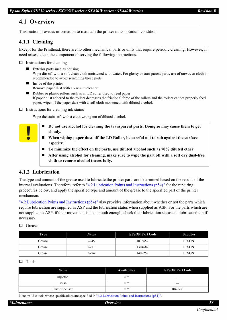
Mai
Epson Stylus SX230 series / SX235W series / SX430W series / SX440W series Revision B
4.1 OverviewThis section provides information to maintain the printer in its optimum condition.
4.1.1 CleaningExcept for the Printhead, there are no other mechanical parts or units that require periodic cleaning. However, if need arises, clean the component observing the following instructions.
Instructions for cleaningExterior parts such as housingWipe dirt off with a soft clean cloth moistened with water. For glossy or transparent parts, use of unwoven cloth is recommended to avoid scratching those parts.Inside of the printerRemove paper dust with a vacuum cleaner.Rubber or plastic rollers such as an LD roller used to feed paperIf paper dust adhered to the rollers decreases the frictional force of the rollers and the rollers cannot properly feed paper, wipe off the paper dust with a soft cloth moistened with diluted alcohol.
Instructions for cleaning ink stains
Wipe the stains off with a cloth wrung out of diluted alcohol.
4.1.2 LubricationThe type and amount of the grease used to lubricate the printer parts are determined based on the results of the internal evaluations. Therefore, refer to "4.2 Lubrication Points and Instructions (p54)" for the repairing procedures below, and apply the specified type and amount of the grease to the specified part of the printer mechanism."4.2 Lubrication Points and Instructions (p54)" also provides information about whether or not the parts which require lubrication are supplied as ASP and the lubrication status when supplied as ASP. For the parts which are not supplied as ASP, if their movement is not smooth enough, check their lubrication status and lubricate them if necessary.
Grease
Tools
Note *: Use tools whose specifications are specified in "4.2 Lubrication Points and Instructions (p54)".
Do not use alcohol for cleaning the transparent parts. Doing so may cause them to get cloudy. When wiping paper dust off the LD Roller, be careful not to rub against the surface asperity.To minimize the effect on the parts, use diluted alcohol such as 70% diluted ether.After using alcohol for cleaning, make sure to wipe the part off with a soft dry dust-free cloth to remove alcohol traces fully.
Type Name EPSON Part Code Supplier
Grease G-45 1033657 EPSON
Grease G-71 1304682 EPSON
Grease G-74 1409257 EPSON
Name Availability EPSON Part Code
Injector O * ---
Brush O * ---
Flux dispenser O * 1049533
Confidential
ntenance Overview 53

Eps Revision B
ConfidentialMai 54
4.2
re 4-3. Lubrication of the Frame Base (3)
<Part supply as ASP>None<Lubrication status when supplied as ASP>---
<Lubrication Point>1. Contact points (x2) on
the Frame Base with the Paper Support Assy
2. Contact points (x7) on the Frame Base with the Stacker Assy
<Type>G-74
<Application Amount>Appropriate amount
<Remarks>Apply with flux dispenser.Stir G-74 before use.
Rear right
Apply inside the groove
Bottom
Apply grease on both sides of dowels
Apply grease on ribs
2. Application Point1. Application Point
Frame Base
ntenance
Figure 4-2. Lubrication of the Frame Base (2)
Apply grease inside the rail section. Apply grease inside the rail se
Lubrication Points and Instructions
Appropriate amount
<Remarks>Apply with flux dispenser.Stir G-74 before use.
ction.
Figu
Apply grease on ribs
Apply grease on ribs
on Stylus SX230 series / SX235W series / SX430W series / SX440W series
Lubrication Points and Instructions
Figure 4-1. Lubrication of the Frame Base (1)
<Part supply as ASP>None<Lubrication status when supplied as ASP>---
<Lubrication Point>Contact points (x12) on the Frame Base with the EJ Roller
<Type>G-74
<Application Amount>Appropriate amount
<Remarks>Apply with flux dispenser.Stir G-74 before use.
Frame Base
Application Point
<Part supply as ASP>None<Lubrication status when supplied as ASP>---
<Lubrication Point>Contact points (x2) on the Frame Base with the Panel Assy
<Type>G-74
<Application Amount>Application Point
Frame Base
Rear left
Apply inside the groove

Eps Revision B
ConfidentialMai 55
oller Gear Figure 4-7. Lubrication of the CR Driven Pulley Assy
supply as ASP>
ication status when ed as ASP>bricated
ication Point>on the EJ Roller Gear
>
lication Amount>m x 1 circle
arks>ing injector, apply ase along the tier on shaft.bricate before aching the part.
<Part supply as ASP>None<Lubrication status when supplied as ASP>---<Lubrication Point>1. On the bearings (x2) of the
CR Driven Pulley on the CR Driven Pulley Holder
2. Contact points (x4) on the groove of the CR Driven Pulley Holder with the Main Frame
<Type>G-71<Application Amount>Appropriate amount<Remarks>1. After applying with
injector, attach the CR Driven Pulley and rotate it twice to spread grease.
2. Apply with injector. Wipe the grease that run off the CR Driven Pulley Holder.Check the lubrication condition and apply grease if necessary.
CR Driven Pulley Holder
2. Application Point1. Application Point
Back Lever
supply as ASP>
ication status when ed as ASP>bricated
ication Point>ct points (x2) on the Back Lever with the Base
>
lication Amount> x 2 points
arks>ply with injector.bricate before ching the part.
ntenance
Figure 4-8. Lubrication of the PF Roller
PF Roller
Appl
Frame Base
on Stylus SX230 series / SX235W series / SX430W series / SX440W series
Figure 4-4. Lubrication of the LD Roller Assy Figure 4-5. Lu
<Part supply as ASP>Yes<Lubrication status when supplied as ASP>Not lubricated
<Lubrication Point>1. Cam of the LD Roller
Assy (contact point with the Hopper)
2. Cam of the LD Roller Assy (contact point with the Paper Back Lever)
<Type>G-71
<Application Amount>Circumference of each cam (0.05 g each)
<Remarks>Apply with injector.Lubricate before attaching the part.
LD Roller Assy
2. Application Point1. Application Point
EJ Roller
Appl
Frame Base
Lubrication Points and Instructions
On each contact point around the shaft(appropriate amount)
<Remarks>Apply with injector.Lubricate before attaching the part.
ication Point
Figure 4-9. Lubrication of the Paper
0.06 g
<RemApLuatta
Application Point
brication of the EJ Roller
<Part supply as ASP>Yes<Lubrication status when supplied as ASP>Not lubricated
<Lubrication Point>Contact point (x1 on the shaft) on the EJ Roller with the Frame Base
<Type>G-71
<Application Amount>0.06 g
<Remarks>Apply with injector.Lubricate before attaching the part.
ication Point
Figure 4-6. Lubrication of the EJ R
<Part Yes<LubrsuppliNot lu
<LubrShaft
<TypeG-71
<Appφ 1 m
<RemUsgretheLuatt
EJ Roller Gear
Application Point
<Part supply as ASP>Yes<Lubrication status when supplied as ASP>Not lubricated
<Lubrication Point>Contact points (x3 on the shaft) on the PF Roller with the Frame Base
<Type>G-71
<Application Amount>
<Part Yes<LubrsuppliNot lu
<LubrContaPaperFrame
<TypeG-71
<App
Paper Back Lever

Eps Revision B
ConfidentialMai 56
-12. Lubrication of the Scanner Carriage (1)
<Part supply as ASP>Supplied as the Scanner Unit<Lubrication status when supplied as ASP>Lubricated
<Lubrication Point>Contact points (x6) on the Scanner Carriage with the CIS Module Unit
<Type>G-74
<Application Amount>Appropriate amount
<Remarks>Apply with flux dispenser.Stir G-74 before use.For section A, apply grease over the area shown in the Cross-section view.
Section A (See Cross-section view.)
Cross-section of section A
CIS Module Unit
Application Point
ntenance
Figure 4-11. Lubrication of the Scanner Housing Low
Scanner Housing Lower
Appl
Lubrication Points and Instructions
er
0.03 g x 3 points
<Remarks>After applying with injector, spread it with brush in the direction of the arrow.
ication Point
Figure 4
on Stylus SX230 series / SX235W series / SX430W series / SX440W series
Figure 4-10. Lubrication of the Main Frame Assy
<Part supply as ASP>None<Lubrication status when supplied as ASP>---
<Lubrication Point>1. Contact point (x1) on
the upper side of the Main Frame Assy with the CR Unit
2. Contact points (x4) on the lower side of the Main Frame Assy with the CR Unit
<Type>G-71
<Application Amount>Appropriate amount
<Remarks>Apply with injector.
Main Frame Assy
CR Unit
Application Point
Main Frame Assy
Frame Base
<Part supply as ASP>Supplied as the Scanner Unit<Lubrication status when supplied as ASP>Lubricated
<Lubrication Point>Guide rail of the Scanner Housing Lower
<Type>G-45
<Application Amount>
Spread grease with brush.
Guide rail
Section A (See Cross-section view.)
Scanner Carriage

Eps Revision B
ConfidentialMai 57
ure 4-14. Lubrication of the Panel Stand
<Part supply as ASP>Supplied as the Panel Unit<Lubrication status when supplied as ASP>Lubricated
<Lubrication Point>Shafts (x4) of the Panel Stand
<Type>G-74
<Application Amount>Appropriate amount
<Remarks>Using flux dispenser, apply all over the shafts shown in the figure.Stir G-74 before use.
Panel Stand
Application Point
C
ntenance
Figure 4-15. Lubrication of Scanner Motor, Combination Gear 14.4,10.8 and
Scanner Motor
Pinion Gear
Appli
on Stylus SX230 series / SX235W series / SX430W series / SX440W series
Figure 4-13. Lubrication of the Scanner Carriage (2
Scanner Carriage
Enlarged figure Apply on the center of inner
wall (x4 points).
Applicatio
Scanner Carriage
ross-section Cross-section
Combination gear 14.4,10.8 Combination gear
Lubrication Points and Instructions
Combination Gear 13.8,9.66
<Type>G-45
<Application Amount>1. 0.01 g x 2 points2.3. 0.01 g
<Remarks>1. Apply with injector.2.3. After applying with
injector, spread it over the entire inner surface the shaft hole shown in the figure.
Be careful not to let grease flow over.cation Point
)
<Part supply as ASP>Supplied as the Scanner Unit<Lubrication status when supplied as ASP>Lubricated
<Lubrication Point>On inner wall surfaces (x4) on the groove of the Scanner Carriage
<Type>G-45
<Application Amount>0.01 g x 4 points
<Remarks>Using injector, apply grease on inner wall surfaces (x4) on the groove shown in the enlarged figure.Be careful not to let grease flow over.
n Point
Fig
<Part supply as ASP>Supplied as the Scanner Unit<Lubrication status when supplied as ASP>Lubricated
<Lubrication Point>1. Gear sections (x2) on the
Pinion Gear of the Scanner Motor
2. Shaft hole of the Combination Gear 14.4.10.8
3. Shaft hole of the Combination Gear 13.8.9.66
13.8,9.66

CHAPTER
5REFURBISHMENT
Confidential
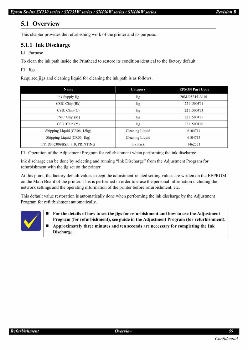
Ref
Epson Stylus SX230 series / SX235W series / SX430W series / SX440W series Revision B
5.1 OverviewThis chapter provides the refurbishing work of the printer and its purpose.
5.1.1 Ink DischargePurpose
To clean the ink path inside the Printhead to restore its condition identical to the factory default.
Jigs
Required jigs and cleaning liquid for cleaning the ink path is as follows.
Operation of the Adjustment Program for refurbishment when performing the ink discharge
Ink discharge can be done by selecting and running “Ink Discharge” from the Adjustment Program for refurbishment with the jig set on the printer.
At this point, the factory default values except the adjustment-related setting values are written on the EEPROM on the Main Board of the printer. This is performed in order to erase the personal information including the network settings and the operating information of the printer before refurbishment, etc.
This default value restoration is automatically done when performing the ink discharge by the Adjustment Program for refurbishment automatically.
Name Category EPSON Part Code
Ink Supply Jig Jig 20MJ05245-A101
CSIC Chip (Bk) Jig 2211500JT1
CSIC Chip (C) Jig 2211500JT3
CSIC Chip (M) Jig 2211500JT5
CSIC Chip (Y) Jig 2211500JT6
Shipping Liquid (CR06, 18kg) Cleaning Liquid 6104714
Shipping Liquid (CR06, 1kg) Cleaning Liquid 6104713
I/P, DPIC009BSP, 110, PRINTING Ink Pack 1462531
For the details of how to set the jigs for refurbishment and how to use the Adjustment Program (for refurbishment), see guide in the Adjustment Program (for refurbishment).Approximately three minutes and ten seconds are necessary for completing the Ink Discharge.
Confidential
urbishment Overview 59

CHAPTER
6APPENDIX
Confidential
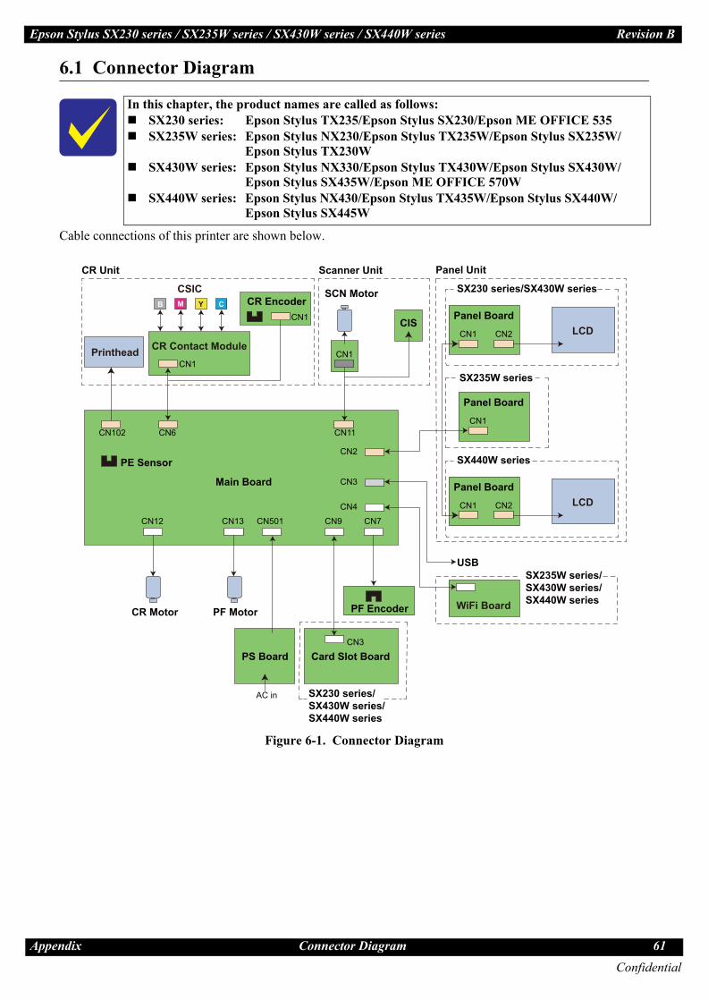
App
Epson Stylus SX230 series / SX235W series / SX430W series / SX440W series Revision B
6.1 Connector Diagram
Cable connections of this printer are shown below.
Figure 6-1. Connector Diagram
In this chapter, the product names are called as follows:SX230 series: Epson Stylus TX235/Epson Stylus SX230/Epson ME OFFICE 535SX235W series: Epson Stylus NX230/Epson Stylus TX235W/Epson Stylus SX235W/
Epson Stylus TX230WSX430W series: Epson Stylus NX330/Epson Stylus TX430W/Epson Stylus SX430W/
Epson Stylus SX435W/Epson ME OFFICE 570WSX440W series: Epson Stylus NX430/Epson Stylus TX435W/Epson Stylus SX440W/
Epson Stylus SX445W
B M Y C
SX230 series/SX430W series/SX440W series
CN501 CN9 CN7CN13CN12
CN6 CN11CN102
Printhead
CIS
PE Sensor
CR Motor
SCN Motor
PF Motor
USB
CN3
Panel Board
CN2
CN4
PF Encoder
CR Encoder
WiFi Board
AC in
PS BoardCN3
Card Slot Board
Main Board
Scanner Unit
CN1
CN1
CN1
CN1
Panel BoardLCDCN1 CN2
CSIC
CR Contact Module
CR Unit Panel Unit
SX230 series/SX430W series
Panel BoardLCDCN1 CN2
SX440W series
SX235W series/SX430W series/SX440W series
SX235W series
Confidential
endix Connector Diagram 61
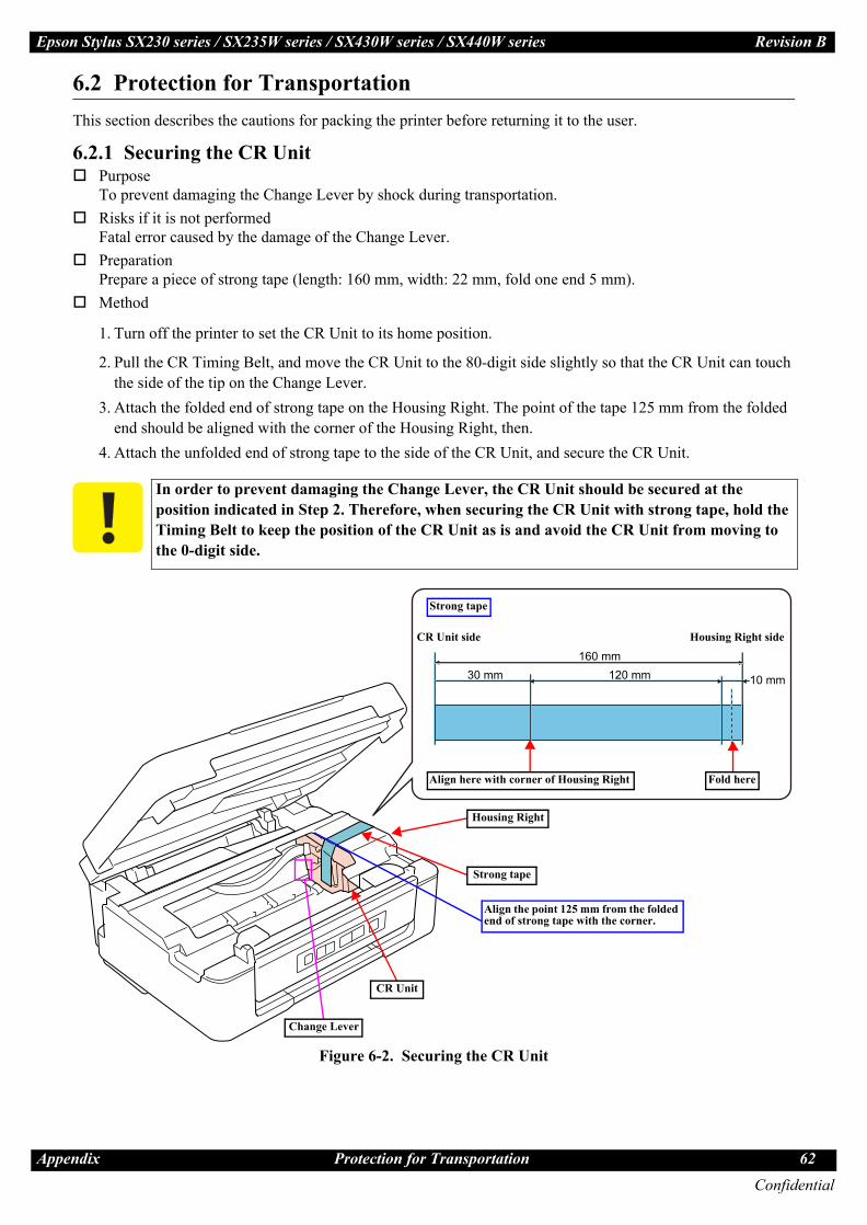
App
Epson Stylus SX230 series / SX235W series / SX430W series / SX440W series Revision B
6.2 Protection for TransportationThis section describes the cautions for packing the printer before returning it to the user.
6.2.1 Securing the CR UnitPurposeTo prevent damaging the Change Lever by shock during transportation.Risks if it is not performedFatal error caused by the damage of the Change Lever.PreparationPrepare a piece of strong tape (length: 160 mm, width: 22 mm, fold one end 5 mm).Method
1. Turn off the printer to set the CR Unit to its home position.
2. Pull the CR Timing Belt, and move the CR Unit to the 80-digit side slightly so that the CR Unit can touch the side of the tip on the Change Lever.
3. Attach the folded end of strong tape on the Housing Right. The point of the tape 125 mm from the folded end should be aligned with the corner of the Housing Right, then.
4. Attach the unfolded end of strong tape to the side of the CR Unit, and secure the CR Unit.
Figure 6-2. Securing the CR Unit
In order to prevent damaging the Change Lever, the CR Unit should be secured at the position indicated in Step 2. Therefore, when securing the CR Unit with strong tape, hold the Timing Belt to keep the position of the CR Unit as is and avoid the CR Unit from moving to the 0-digit side.
10 mm120 mm30 mm160 mm
Align the point 125 mm from the folded end of strong tape with the corner.
Strong tape
CR Unit
Housing Right
Change Lever
Align here with corner of Housing Right Fold here
CR Unit side Housing Right side
Strong tape
Confidential
endix Protection for Transportation 62
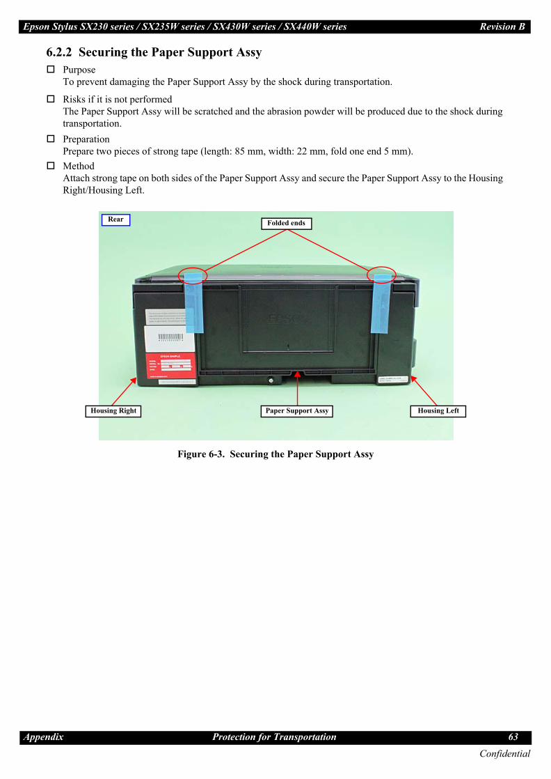
App
Epson Stylus SX230 series / SX235W series / SX430W series / SX440W series Revision B
6.2.2 Securing the Paper Support AssyPurposeTo prevent damaging the Paper Support Assy by the shock during transportation.
Risks if it is not performedThe Paper Support Assy will be scratched and the abrasion powder will be produced due to the shock during transportation.PreparationPrepare two pieces of strong tape (length: 85 mm, width: 22 mm, fold one end 5 mm).MethodAttach strong tape on both sides of the Paper Support Assy and secure the Paper Support Assy to the Housing Right/Housing Left.
Figure 6-3. Securing the Paper Support Assy
Rear Folded ends
Paper Support Assy Housing LeftHousing Right
Confidential
endix Protection for Transportation 63


