NX-TS Temperature Input Units Datasheet...None 10 A NX-TBA162---C/D NX-TBB162 Item Specification...
27
CSM_NX-TS_DS_E_3_1 1 NX-series Temperature Input Unit NX-TS Temperature Input Units for Standard and High-speed, High-precision Temperature measurement and control • Temperature Input Units for the NX-series modular I/O system. • Connect to other NX-series I/O Units and EtherCAT Coupler units using the high-speed NX-bus. • Thermocouple and platinum resistance thermometer input models are available. Features • Input up to four temperature sensor signals with one Unit. • Three sampling speeds, 250 ms, 60 ms, and 10 ms, are available to cover a wide range from general-purpose application to high-speed, high- precision control. • Moving average, input sensor disconnection detection function, cold junction compensation enable/disable selection function, and input compensation. • The screwless terminal block is detachable for easy commissioning and maintenance. • Screwless push-in terminal block significantly reduces wiring work. System Configuration * OMRON CJ1W-NC@81/@82 Position Control Units cannot be connected to the EtherCAT Slave Terminal even though they support EtherCAT. Sysmac ® is a trademark or registered trademark of OMRON Corporation in Japan and other countries for OMRON factory automation products. EtherCAT ® is a registered trademark of Beckhoff Automation GmbH for their patented technology. Other company names and product names in this document are the trademarks or registered trademarks of their respective companies. NX-TS2201 NX-TS3201 NX-TS3101 NX-TS2101 EtherCAT master* NJ-series CPU Unit Communications cable Ethernet cables NX Series EtherCAT Coupler Unit NX-ECC@@@ ●EtherCAT Slave Terminal Sysmac Studio Support Software Sysmac Studio Support Software End Cover NX Units Built-in EtherCAT port Connection to peripheral USB port or built-in EtherNet/IP port on NJ-series CPU Unit Connection to peripheral USB port on EtherCAT Coupler Unit Peripheral USB port.
Transcript of NX-TS Temperature Input Units Datasheet...None 10 A NX-TBA162---C/D NX-TBB162 Item Specification...
CSM_NX-TS_DS_E_3_1
1
NX-series Temperature Input Unit
NX-TSTemperature Input Units for Standard and High-speed, High-precision Temperature measurement and control
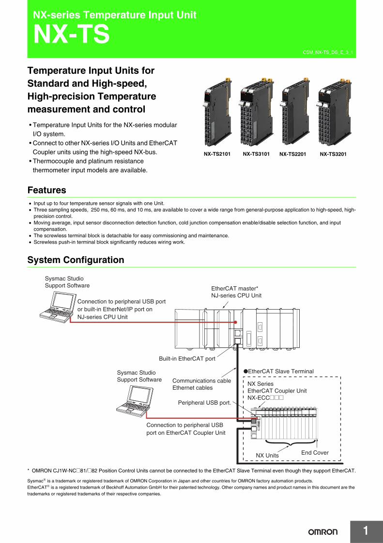
• Temperature Input Units for the NX-series modular I/O system.
• Connect to other NX-series I/O Units and EtherCAT Coupler units using the high-speed NX-bus.
• Thermocouple and platinum resistance thermometer input models are available.
Features• Input up to four temperature sensor signals with one Unit.• Three sampling speeds, 250 ms, 60 ms, and 10 ms, are available to cover a wide range from general-purpose application to high-speed, high-
precision control. • Moving average, input sensor disconnection detection function, cold junction compensation enable/disable selection function, and input
compensation.• The screwless terminal block is detachable for easy commissioning and maintenance.• Screwless push-in terminal block significantly reduces wiring work.
System Configuration
* OMRON CJ1W-NC@81/@82 Position Control Units cannot be connected to the EtherCAT Slave Terminal even though they support EtherCAT.
Sysmac® is a trademark or registered trademark of OMRON Corporation in Japan and other countries for OMRON factory automation products.EtherCAT® is a registered trademark of Beckhoff Automation GmbH for their patented technology. Other company names and product names in this document are the trademarks or registered trademarks of their respective companies.
NX-TS2201 NX-TS3201NX-TS3101NX-TS2101
EtherCAT master*NJ-series CPU Unit
Communications cableEthernet cables
NX Series EtherCAT Coupler UnitNX-ECC@@@
●EtherCAT Slave Terminal
Sysmac Studio Support Software
Sysmac Studio Support Software
End CoverNX Units
Built-in EtherCAT port
Connection to peripheral USB port or built-in EtherNet/IP port on NJ-series CPU Unit
Connection to peripheral USB port on EtherCAT Coupler Unit
Peripheral USB port.
NX-TS
2
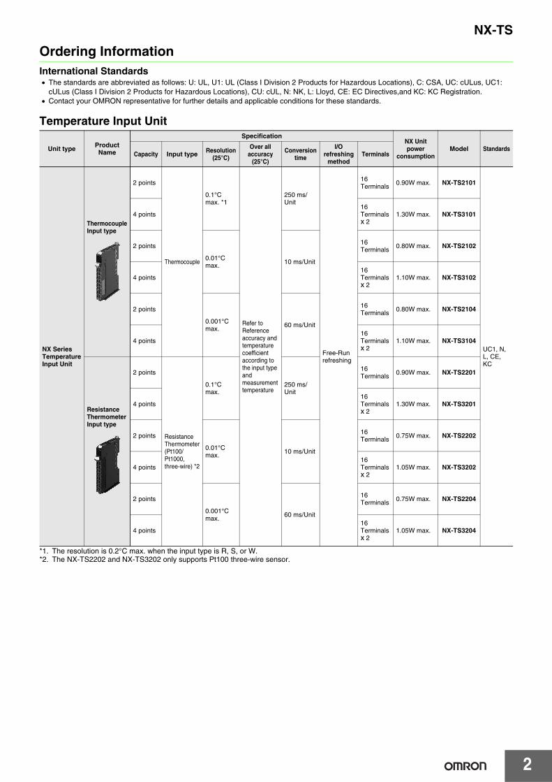
Ordering InformationInternational Standards• The standards are abbreviated as follows: U: UL, U1: UL (Class I Division 2 Products for Hazardous Locations), C: CSA, UC: cULus, UC1:
cULus (Class I Division 2 Products for Hazardous Locations), CU: cUL, N: NK, L: Lloyd, CE: EC Directives,and KC: KC Registration.• Contact your OMRON representative for further details and applicable conditions for these standards.
Temperature Input Unit
*1. The resolution is 0.2°C max. when the input type is R, S, or W.*2. The NX-TS2202 and NX-TS3202 only supports Pt100 three-wire sensor.
Unit type Product Name
SpecificationNX Unit power
consumptionModel Standards
Capacity Input type Resolution(25°C)
Over all accuracy
(25°C)
Conversion time
I/O refreshing
methodTerminals
NX Series Temperature Input Unit
ThermocoupleInput type
2 points
Thermocouple
0.1°C max. *1
Refer to Reference accuracy and temperature coefficient according to the input type and measurement temperature
250 ms/Unit
Free-Run refreshing
16Terminals
0.90W max. NX-TS2101
UC1, N, L, CE, KC
4 points16Terminalsx 2
1.30W max. NX-TS3101
2 points
0.01°C max. 10 ms/Unit
16Terminals 0.80W max. NX-TS2102
4 points16Terminalsx 2
1.10W max. NX-TS3102
2 points
0.001°C max. 60 ms/Unit
16Terminals 0.80W max. NX-TS2104
4 points16Terminalsx 2
1.10W max. NX-TS3104
Resistance Thermometer Input type
2 points
Resistance Thermometer(Pt100/Pt1000, three-wire) *2
0.1°C max.
250 ms/Unit
16Terminals 0.90W max. NX-TS2201
4 points16Terminalsx 2
1.30W max. NX-TS3201
2 points
0.01°C max. 10 ms/Unit
16Terminals 0.75W max. NX-TS2202
4 points16Terminalsx 2
1.05W max. NX-TS3202
2 points
0.001°C max. 60 ms/Unit
16Terminals 0.75W max. NX-TS2204
4 points16Terminalsx 2
1.05W max. NX-TS3204
3
NX-TS
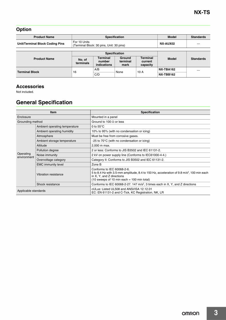
Option
AccessoriesNot included.
General Specification
Product Name Specification Model Standards
Unit/Terminal Block Coding Pins For 10 Units(Terminal Block: 30 pins, Unit: 30 pins) NX-AUX02 ---
Product Name
Specification
Model StandardsNo. of terminals
Terminal number
indications
Ground terminal
mark
Terminal current
capacity
Terminal Block 16A/B
None 10 ANX-TBA162 ---
C/D NX-TBB162
Item Specification
Enclosure Mounted in a panel
Grounding method Ground to 100 Ω or less
Operating environment
Ambient operating temperature 0 to 55°C
Ambient operating humidity 10% to 95% (with no condensation or icing)
Atmosphere Must be free from corrosive gases.
Ambient storage temperature −25 to 70°C (with no condensation or icing)
Altitude 2,000 m max.
Pollution degree 2 or less: Conforms to JIS B3502 and IEC 61131-2.
Noise immunity 2 kV on power supply line (Conforms to IEC61000-4-4.)
Overvoltage category Category II: Conforms to JIS B3502 and IEC 61131-2.
EMC immunity level Zone B
Vibration resistance
Conforms to IEC 60068-2-6.5 to 8.4 Hz with 3.5-mm amplitude, 8.4 to 150 Hz, acceleration of 9.8 m/s2, 100 min each in X, Y, and Z directions (10 sweeps of 10 min each = 100 min total)
Shock resistance Conforms to IEC 60068-2-27. 147 m/s2, 3 times each in X, Y, and Z directions
Applicable standards cULus: Listed UL508 and ANSI/ISA 12.12.01EC: EN 61131-2 and C-Tick, KC Registration, NK, LR
NX-TS
4
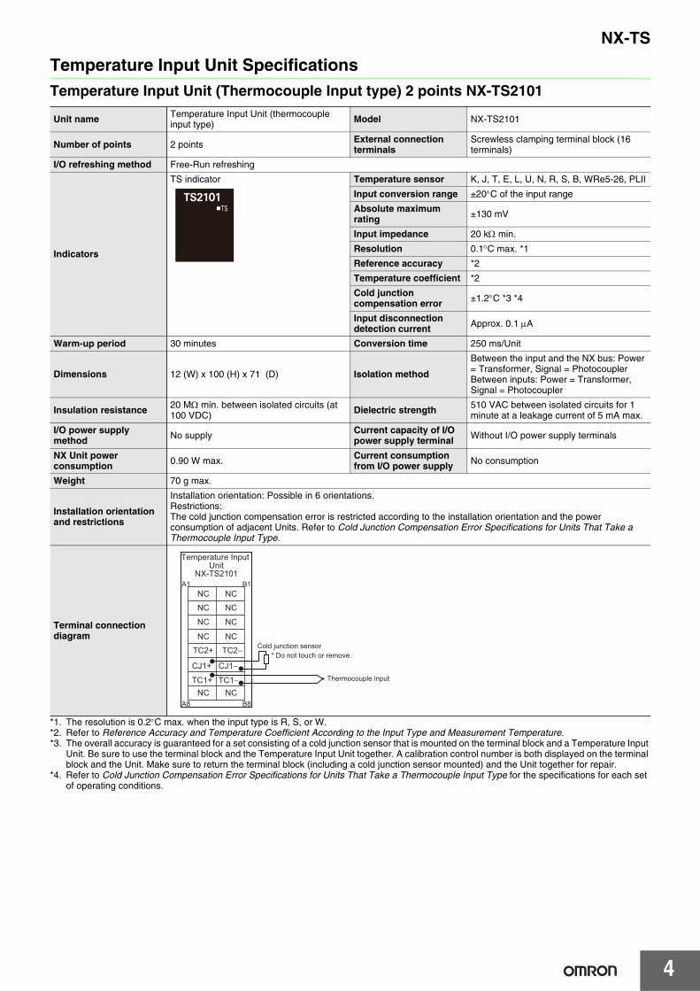
Temperature Input Unit SpecificationsTemperature Input Unit (Thermocouple Input type) 2 points NX-TS2101
*1. The resolution is 0.2°C max. when the input type is R, S, or W.*2. Refer to Reference Accuracy and Temperature Coefficient According to the Input Type and Measurement Temperature.*3. The overall accuracy is guaranteed for a set consisting of a cold junction sensor that is mounted on the terminal block and a Temperature Input
Unit. Be sure to use the terminal block and the Temperature Input Unit together. A calibration control number is both displayed on the terminal block and the Unit. Make sure to return the terminal block (including a cold junction sensor mounted) and the Unit together for repair.
*4. Refer to Cold Junction Compensation Error Specifications for Units That Take a Thermocouple Input Type for the specifications for each set of operating conditions.
Unit name Temperature Input Unit (thermocouple input type) Model NX-TS2101
Number of points 2 points External connection terminals
Screwless clamping terminal block (16 terminals)
I/O refreshing method Free-Run refreshing
Indicators
TS indicator Temperature sensor K, J, T, E, L, U, N, R, S, B, WRe5-26, PLII
Input conversion range ±20°C of the input range
Absolute maximum rating ±130 mV
Input impedance 20 kΩ min.
Resolution 0.1°C max. *1
Reference accuracy *2
Temperature coefficient *2
Cold junction compensation error ±1.2°C *3 *4
Input disconnection detection current Approx. 0.1 μA
Warm-up period 30 minutes Conversion time 250 ms/Unit
Dimensions 12 (W) x 100 (H) x 71 (D) Isolation method
Between the input and the NX bus: Power = Transformer, Signal = PhotocouplerBetween inputs: Power = Transformer, Signal = Photocoupler
Insulation resistance 20 MΩ min. between isolated circuits (at 100 VDC) Dielectric strength 510 VAC between isolated circuits for 1
minute at a leakage current of 5 mA max.
I/O power supply method No supply Current capacity of I/O
power supply terminal Without I/O power supply terminals
NX Unit power consumption 0.90 W max. Current consumption
from I/O power supply No consumption
Weight 70 g max.
Installation orientation and restrictions
Installation orientation: Possible in 6 orientations.Restrictions:The cold junction compensation error is restricted according to the installation orientation and the power consumption of adjacent Units. Refer to Cold Junction Compensation Error Specifications for Units That Take a Thermocouple Input Type.
Terminal connection diagram
Cold junction sensor
NC NCA1 B1
A8 B8
NC NC
TC2+ TC2−
TC1+ TC1−
NC NC
NC NC
CJ1+ CJ1−
NC NC
Temperature Input Unit
NX-TS2101
* Do not touch or remove.
Thermocouple input

5
NX-TS
Temperature Input Unit (Thermocouple Input type) 2 points NX-TS2102
*1. Refer to Reference Accuracy and Temperature Coefficient According to the Input Type and Measurement Temperature.*2. The overall accuracy is guaranteed for a set consisting of a cold junction sensor that is mounted on the terminal block and a Temperature Input
Unit. Be sure to use the terminal block and the Temperature Input Unit together. A calibration control number is both displayed on the terminal block and the Unit. Make sure to return the terminal block (including a cold junction sensor mounted) and the Unit together for repair.
*3. Refer to Cold Junction Compensation Error Specifications for Units That Take a Thermocouple Input Type for the specifications for each set of operating conditions.
Unit name Temperature Input Unit (thermocouple input type) Model NX-TS2102
Number of points 2 points External connection terminals
Screwless clamping terminal block (16 terminals)
I/O refreshing method Free-Run refreshing
Indicators
TS indicator Temperature sensor K, J, T, E, L, U, N, R, S, WRe5-26, PLII
Input conversion range ±20°C of the input range
Absolute maximum rating ±130 mV
Input impedance 20 kΩ min.
Resolution 0.01°C max.
Reference accuracy *1
Temperature coefficient *1
Cold junction compensation error ±1.2°C *2 *3
Input disconnection detection current Approx. 0.1 μA
Warm-up period 45 minutes Conversion time 10 ms/Unit
Dimensions 12 (W) x 100 (H) x 71 (D) Isolation method
Between the input and the NX bus: Power = Transformer, Signal = Digital isolator Between inputs: Power = Transformer, Signal = Digital isolator
Insulation resistance 20 MΩ min. between isolated circuits (at 100 VDC) Dielectric strength 510 VAC between isolated circuits for 1
minute at a leakage current of 5 mA max.
I/O power supply method No supply Current capacity of I/O
power supply terminal Without I/O power supply terminals
NX Unit power consumption 0.80 W max. Current consumption
from I/O power supply No consumption
Weight 70 g max.
Installation orientation and restrictions
Installation orientation: Possible in 6 orientations.Restrictions:The cold junction compensation error is restricted according to the installation orientation and the power consumption of adjacent Units. Refer to Cold Junction Compensation Error Specifications for Units That Take a Thermocouple Input Type.
Terminal connection diagram
NC NCA1 B1
A8 B8
NC NC
TC2+ TC2−
TC1+ TC1−
NC NC
NC NC
CJ1+ CJ1−
NC NC
Cold junction sensor* Do not touch or remove.
Thermocouple input
Temperature Input Unit
NX-TS2102
6
NX-TS
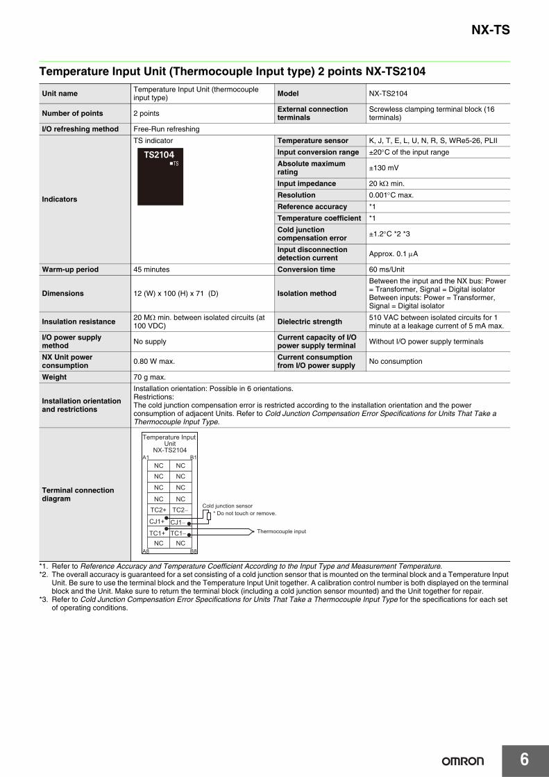
Temperature Input Unit (Thermocouple Input type) 2 points NX-TS2104
*1. Refer to Reference Accuracy and Temperature Coefficient According to the Input Type and Measurement Temperature.*2. The overall accuracy is guaranteed for a set consisting of a cold junction sensor that is mounted on the terminal block and a Temperature Input
Unit. Be sure to use the terminal block and the Temperature Input Unit together. A calibration control number is both displayed on the terminal block and the Unit. Make sure to return the terminal block (including a cold junction sensor mounted) and the Unit together for repair.
*3. Refer to Cold Junction Compensation Error Specifications for Units That Take a Thermocouple Input Type for the specifications for each set of operating conditions.
Unit name Temperature Input Unit (thermocouple input type) Model NX-TS2104
Number of points 2 points External connection terminals
Screwless clamping terminal block (16 terminals)
I/O refreshing method Free-Run refreshing
Indicators
TS indicator Temperature sensor K, J, T, E, L, U, N, R, S, WRe5-26, PLII
Input conversion range ±20°C of the input range
Absolute maximum rating ±130 mV
Input impedance 20 kΩ min.
Resolution 0.001°C max.
Reference accuracy *1
Temperature coefficient *1
Cold junction compensation error ±1.2°C *2 *3
Input disconnection detection current Approx. 0.1 μA
Warm-up period 45 minutes Conversion time 60 ms/Unit
Dimensions 12 (W) x 100 (H) x 71 (D) Isolation method
Between the input and the NX bus: Power= Transformer, Signal = Digital isolatorBetween inputs: Power = Transformer, Signal = Digital isolator
Insulation resistance 20 MΩ min. between isolated circuits (at 100 VDC) Dielectric strength 510 VAC between isolated circuits for 1
minute at a leakage current of 5 mA max.
I/O power supply method No supply Current capacity of I/O
power supply terminal Without I/O power supply terminals
NX Unit power consumption 0.80 W max. Current consumption
from I/O power supply No consumption
Weight 70 g max.
Installation orientation and restrictions
Installation orientation: Possible in 6 orientations.Restrictions:The cold junction compensation error is restricted according to the installation orientation and the power consumption of adjacent Units. Refer to Cold Junction Compensation Error Specifications for Units That Take a Thermocouple Input Type.
Terminal connection diagram
NC NCA1 B1
A8 B8
NC NC
TC2+ TC2−
TC1+ TC1−
NC NC
NC NC
CJ1+ CJ1−
NC NC
Cold junction sensor* Do not touch or remove.
Thermocouple input
Temperature Input Unit
NX-TS2104
7
NX-TS
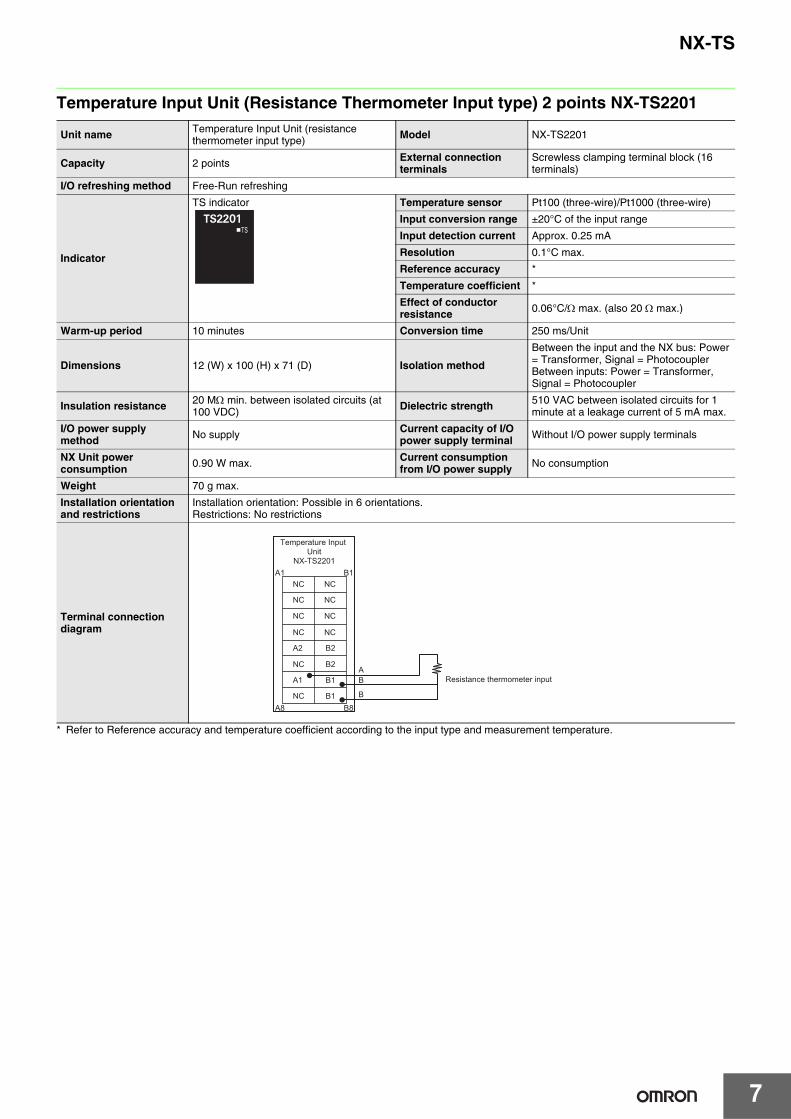
Temperature Input Unit (Resistance Thermometer Input type) 2 points NX-TS2201
* Refer to Reference accuracy and temperature coefficient according to the input type and measurement temperature.
Unit name Temperature Input Unit (resistance thermometer input type) Model NX-TS2201
Capacity 2 points External connection terminals
Screwless clamping terminal block (16 terminals)
I/O refreshing method Free-Run refreshing
Indicator
TS indicator Temperature sensor Pt100 (three-wire)/Pt1000 (three-wire)
Input conversion range ±20°C of the input range
Input detection current Approx. 0.25 mA
Resolution 0.1°C max.
Reference accuracy *
Temperature coefficient *
Effect of conductor resistance 0.06°C/Ω max. (also 20 Ω max.)
Warm-up period 10 minutes Conversion time 250 ms/Unit
Dimensions 12 (W) x 100 (H) x 71 (D) Isolation method
Between the input and the NX bus: Power= Transformer, Signal = PhotocouplerBetween inputs: Power = Transformer, Signal = Photocoupler
Insulation resistance 20 MΩ min. between isolated circuits (at 100 VDC) Dielectric strength 510 VAC between isolated circuits for 1
minute at a leakage current of 5 mA max.
I/O power supply method No supply Current capacity of I/O
power supply terminal Without I/O power supply terminals
NX Unit power consumption 0.90 W max. Current consumption
from I/O power supply No consumption
Weight 70 g max.
Installation orientation and restrictions
Installation orientation: Possible in 6 orientations.Restrictions: No restrictions
Terminal connection diagram
AB
B
NC NCA1 B1
A8 B8
NC NC
A2 B2
A1 B1
NC NC
NC NC
NC B2
NC B1
Temperature Input Unit
NX-TS2201
Resistance thermometer input

8
NX-TS
Temperature Input Unit (Resistance Thermometer Input type) 2 points NX-TS2202
* Refer to Reference accuracy and temperature coefficient according to the input type and measurement temperature.
Unit name Temperature Input Unit (resistance thermometer input type) Model NX-TS2202
Capacity 2 points External connection terminals
Screwless clamping terminal block (16 terminals)
I/O refreshing method Free-Run refreshing
Indicator
TS indicator Temperature sensor Pt100 (three-wire)
Input conversion range ±20°C of the input range
Input detection current Approx. 0.25 mA
Resolution 0.01°C max.
Reference accuracy *
Temperature coefficient *
Effect of conductor resistance 0.06°C/Ω max. (also 20 Ω max.)
Warm-up period 30 minutes Conversion time 10 ms/Unit
Dimensions 12 (W) x 100 (H) x 71 (D) Isolation method
Between the input and the NX bus: Power= Transformer, Signal = Digital isolatorBetween inputs: Power = Transformer, Signal = Digital isolator
Insulation resistance 20 MΩ min. between isolated circuits (at 100 VDC) Dielectric strength 510 VAC between isolated circuits for 1
minute at a leakage current of 5 mA max.
I/O power supply method No supply Current capacity of I/O
power supply terminal Without I/O power supply terminals
NX Unit power consumption 0.75 W max. Current consumption
from I/O power supply No consumption
Weight 70 g max.
Installation orientation and restrictions
Installation orientation: Possible in 6 orientations.Restrictions: No restrictions
Terminal connection diagram
ABB
NC NCA1 B1
A8 B8
NC NC
A2 B2
A1 B1
NC NC
NC NC
NC B2
NC B1Resistance thermometer input
Temperature Input Unit
NX-TS2202
9
NX-TS
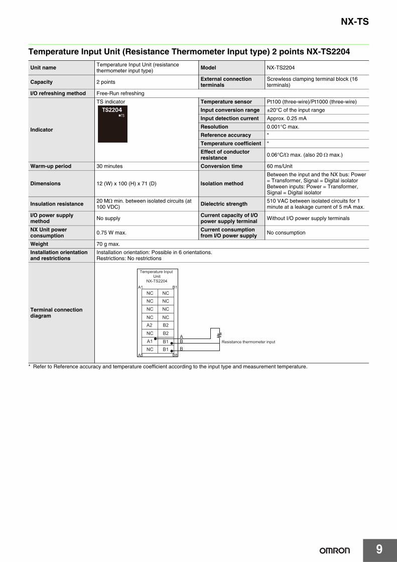
Temperature Input Unit (Resistance Thermometer Input type) 2 points NX-TS2204
* Refer to Reference accuracy and temperature coefficient according to the input type and measurement temperature.
Unit name Temperature Input Unit (resistance thermometer input type) Model NX-TS2204
Capacity 2 points External connection terminals
Screwless clamping terminal block (16 terminals)
I/O refreshing method Free-Run refreshing
Indicator
TS indicator Temperature sensor Pt100 (three-wire)/Pt1000 (three-wire)
Input conversion range ±20°C of the input range
Input detection current Approx. 0.25 mA
Resolution 0.001°C max.
Reference accuracy *
Temperature coefficient *
Effect of conductor resistance 0.06°C/Ω max. (also 20 Ω max.)
Warm-up period 30 minutes Conversion time 60 ms/Unit
Dimensions 12 (W) x 100 (H) x 71 (D) Isolation method
Between the input and the NX bus: Power= Transformer, Signal = Digital isolatorBetween inputs: Power = Transformer, Signal = Digital isolator
Insulation resistance 20 MΩ min. between isolated circuits (at 100 VDC) Dielectric strength 510 VAC between isolated circuits for 1
minute at a leakage current of 5 mA max.
I/O power supply method No supply Current capacity of I/O
power supply terminal Without I/O power supply terminals
NX Unit power consumption 0.75 W max. Current consumption
from I/O power supply No consumption
Weight 70 g max.
Installation orientation and restrictions
Installation orientation: Possible in 6 orientations.Restrictions: No restrictions
Terminal connection diagram
ABB
NC NCA1 B1
A8 B8
NC NC
A2 B2
A1 B1
NC NC
NC NC
NC B2
NC B1Resistance thermometer input
Temperature Input Unit
NX-TS2204

10
NX-TS
Temperature Input Unit (Thermocouple Input type) 4 points NX-TS3101
*1. The resolution is 0.2°C max. when the input type is R, S, or W.*2. Refer to Reference Accuracy and Temperature Coefficient According to the Input Type and Measurement Temperature.*3. The overall accuracy is guaranteed for a set consisting of a cold junction sensor that is mounted on the terminal block and a Temperature Input
Unit. Be sure to use the terminal block and the Temperature Input Unit together. A calibration control number is both displayed on the terminal block and the Unit. Make sure to return the terminal block (including a cold junction sensor mounted) and the Unit together for repair.
*4. Refer to Cold Junction Compensation Error Specifications for Units That Take a Thermocouple Input Type for the specifications for each set of operating conditions.
Unit name Temperature Input Unit (thermocouple input type) Model NX-TS3101
Number of points 4 points External connection terminals
Screwless clamping terminal block (16 terminals x 2)
I/O refreshing method Free-Run refreshing
Indicators
TS indicator Temperature sensor K, J, T, E, L, U, N, R, S, B, WRe5-26, PLII
Input conversion range ±20°C of the input range
Absolute maximum rating ±130 mV
Input impedance 20 kΩ min.
Resolution 0.1°C max. *1
Reference accuracy *2
Temperature coefficient *2
Cold junction compensation error ±1.2°C *3 *4
Input disconnection detection current Approx. 0.1μA
Warm-up period 30 minutes Conversion time 250 ms/Unit
Dimensions 24 (W) x 100 (H) x 71 (D) Isolation method
Between the input and the NX bus: Power = Transformer, Signal = PhotocouplerBetween inputs: Power = Transformer, Signal = Photocoupler
Insulation resistance 20 MΩ min. between isolated circuits (at 100 VDC) Dielectric strength 510 VAC between isolated circuits for 1
minute at a leakage current of 5 mA max.
I/O power supply method No supply Current capacity of I/O
power supply terminal Without I/O power supply terminals
NX Unit power consumption 1.30 W max. Current consumption
from I/O power supply No consumption
Weight 140 g max.
Installation orientation and restrictions
Installation orientation: Possible in 6 orientations.Restrictions:The cold junction compensation error is restricted according to the installation orientation and the power consumption of adjacent Units. Refer to Cold Junction Compensation Error Specifications for Units That Take a Thermocouple Input Type.
Terminal connection diagram
Cold junction sensor
NC NCC1 D1
C8 D8
NC NC
TC4+ TC4−
TC3+ TC3−
NC NC
NC NC
CJ2+ CJ2−
NC NC
NC NCA1 B1
A8 B8
NC NC
TC2+ TC2−
TC1+ TC1−
NC NC
NC NC
CJ1+ CJ1−
NC NC
* Do not touch or remove.
Temperature Input UnitNX-TS3101
Thermocouple input
11
NX-TS
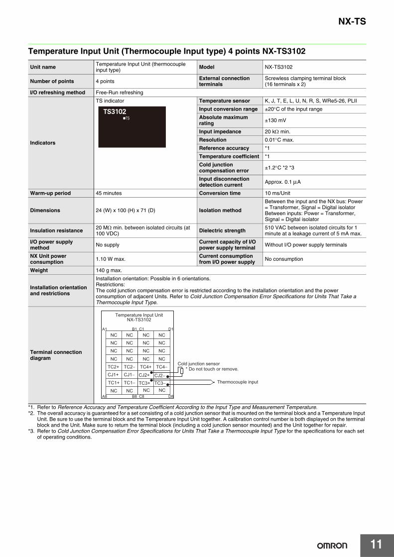
Temperature Input Unit (Thermocouple Input type) 4 points NX-TS3102
*1. Refer to Reference Accuracy and Temperature Coefficient According to the Input Type and Measurement Temperature.*2. The overall accuracy is guaranteed for a set consisting of a cold junction sensor that is mounted on the terminal block and a Temperature Input
Unit. Be sure to use the terminal block and the Temperature Input Unit together. A calibration control number is both displayed on the terminal block and the Unit. Make sure to return the terminal block (including a cold junction sensor mounted) and the Unit together for repair.
*3. Refer to Cold Junction Compensation Error Specifications for Units That Take a Thermocouple Input Type for the specifications for each set of operating conditions.
Unit name Temperature Input Unit (thermocouple input type) Model NX-TS3102
Number of points 4 points External connection terminals
Screwless clamping terminal block (16 terminals x 2)
I/O refreshing method Free-Run refreshing
Indicators
TS indicator Temperature sensor K, J, T, E, L, U, N, R, S, WRe5-26, PLII
Input conversion range ±20°C of the input range
Absolute maximum rating ±130 mV
Input impedance 20 kΩ min.
Resolution 0.01°C max.
Reference accuracy *1
Temperature coefficient *1
Cold junction compensation error ±1.2°C *2 *3
Input disconnection detection current Approx. 0.1 μA
Warm-up period 45 minutes Conversion time 10 ms/Unit
Dimensions 24 (W) x 100 (H) x 71 (D) Isolation method
Between the input and the NX bus: Power = Transformer, Signal = Digital isolatorBetween inputs: Power = Transformer, Signal = Digital isolator
Insulation resistance 20 MΩ min. between isolated circuits (at 100 VDC) Dielectric strength 510 VAC between isolated circuits for 1
minute at a leakage current of 5 mA max.
I/O power supply method No supply Current capacity of I/O
power supply terminal Without I/O power supply terminals
NX Unit power consumption 1.10 W max. Current consumption
from I/O power supply No consumption
Weight 140 g max.
Installation orientation and restrictions
Installation orientation: Possible in 6 orientations.Restrictions:The cold junction compensation error is restricted according to the installation orientation and the power consumption of adjacent Units. Refer to Cold Junction Compensation Error Specifications for Units That Take a Thermocouple Input Type.
Terminal connection diagram
NC NCC1 D1
C8 D8
NC NC
TC4+ TC4−
TC3+ TC3−
NC NC
NC NC
CJ2+ CJ2−
NC NC
NC NCA1 B1
A8 B8
NC NC
TC2+ TC2−
TC1+ TC1−
NC NC
NC NC
CJ1+ CJ1−
NC NC
Cold junction sensor* Do not touch or remove.
Temperature Input UnitNX-TS3102
Thermocouple input

12
NX-TS
Temperature Input Unit (Thermocouple Input type) 4 points NX-TS3104
*1. Refer to Reference Accuracy and Temperature Coefficient According to the Input Type and Measurement Temperature.*2. The overall accuracy is guaranteed for a set consisting of a cold junction sensor that is mounted on the terminal block and a Temperature Input
Unit. Be sure to use the terminal block and the Temperature Input Unit together. A calibration control number is both displayed on the terminal block and the Unit. Make sure to return the terminal block (including a cold junction sensor mounted) and the Unit together for repair.
*3. Refer to Cold Junction Compensation Error Specifications for Units That Take a Thermocouple Input Type for the specifications for each set of operating conditions.
Unit name Temperature Input Unit (thermocouple input type) Model NX-TS3104
Number of points 4 points External connection terminals
Screwless clamping terminal block (16 terminals x 2)
I/O refreshing method Free-Run refreshing
Indicators
TS indicator Temperature sensor K, J, T, E, L, U, N, R, S, WRe5-26, PLII
Input conversion range ±20°C of the input range
Absolute maximum rating ±130 mV
Input impedance 20 kΩ min.
Resolution 0.001°C max.
Reference accuracy *1
Temperature coefficient *1
Cold junction compensation error ±1.2°C *2 *3
Input disconnection detection current Approx. 0.1 μA
Warm-up period 45 minutes Conversion time 60 ms/Unit
Dimensions 24 (W) x 100 (H) x 71 (D) Isolation method
Between the input and the NX bus: Power = Transformer, Signal = Digital isolatorBetween inputs: Power = Transformer, Signal = Digital isolator
Insulation resistance 20 MΩ min. between isolated circuits (at 100 VDC) Dielectric strength 510 VAC between isolated circuits for 1
minute at a leakage current of 5 mA max.
I/O power supply method No supply Current capacity of I/O
power supply terminal Without I/O power supply terminals
NX Unit power consumption 1.10 W max. Current consumption
from I/O power supply No consumption
Weight 140 g max.
Installation orientation and restrictions
Installation orientation: Possible in 6 orientations.Restrictions:The cold junction compensation error is restricted according to the installation orientation and the power consumption of adjacent Units. Refer to Cold Junction Compensation Error Specifications for Units That Take a Thermocouple Input Type.
Terminal connection diagram
NC NCC1 D1
C8 D8
NC NC
TC4+ TC4−
TC3+ TC3−
NC NC
NC NC
CJ2+ CJ2−
NC NC
NC NCA1 B1
A8 B8
NC NC
TC2+ TC2−
TC1+ TC1−
NC NC
NC NC
CJ1+ CJ1−
NC NC
Cold junction sensor* Do not touch or remove.
Temperature Input UnitNX-TS3104
Thermocouple input
13
NX-TS
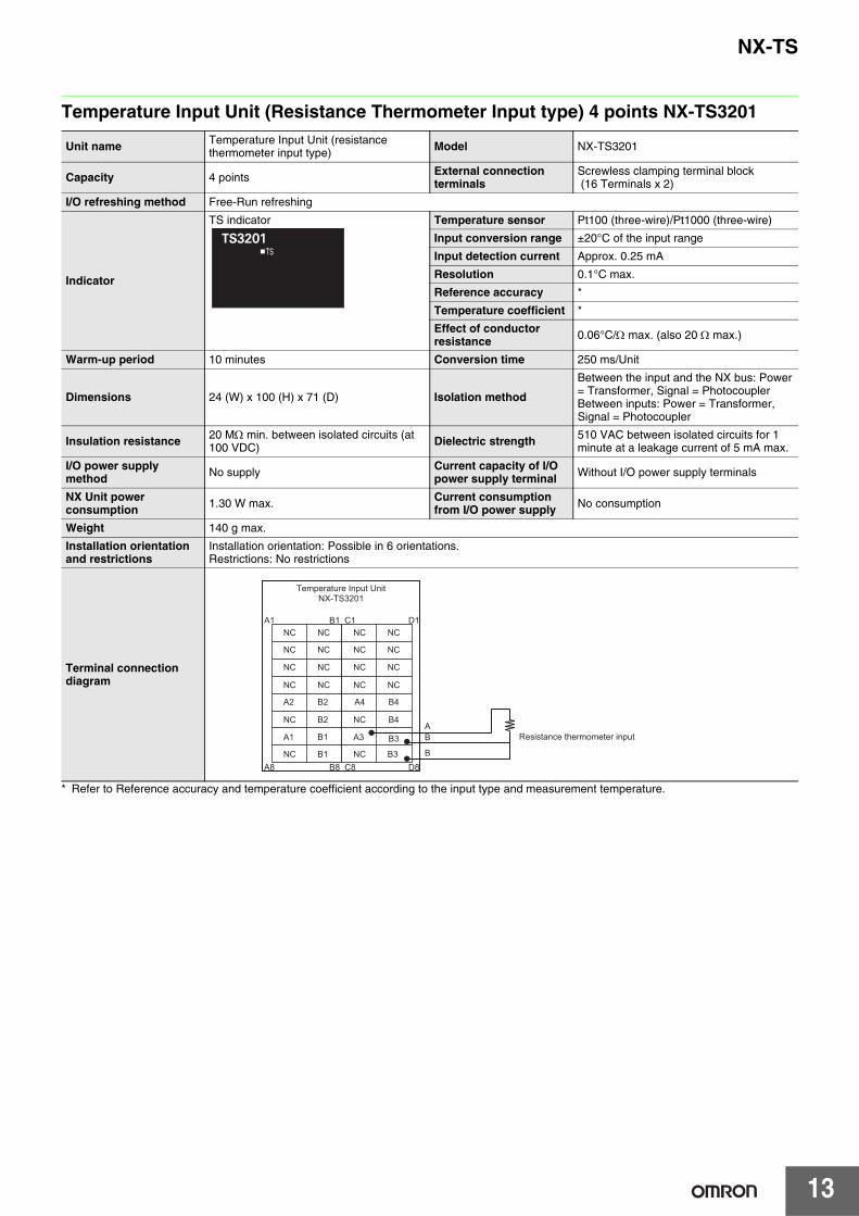
Temperature Input Unit (Resistance Thermometer Input type) 4 points NX-TS3201
* Refer to Reference accuracy and temperature coefficient according to the input type and measurement temperature.
Unit name Temperature Input Unit (resistance thermometer input type) Model NX-TS3201
Capacity 4 points External connection terminals
Screwless clamping terminal block (16 Terminals x 2)
I/O refreshing method Free-Run refreshing
Indicator
TS indicator Temperature sensor Pt100 (three-wire)/Pt1000 (three-wire)
Input conversion range ±20°C of the input range
Input detection current Approx. 0.25 mA
Resolution 0.1°C max.
Reference accuracy *
Temperature coefficient *
Effect of conductor resistance 0.06°C/Ω max. (also 20 Ω max.)
Warm-up period 10 minutes Conversion time 250 ms/Unit
Dimensions 24 (W) x 100 (H) x 71 (D) Isolation method
Between the input and the NX bus: Power= Transformer, Signal = PhotocouplerBetween inputs: Power = Transformer, Signal = Photocoupler
Insulation resistance 20 MΩ min. between isolated circuits (at 100 VDC) Dielectric strength 510 VAC between isolated circuits for 1
minute at a leakage current of 5 mA max.
I/O power supply method No supply Current capacity of I/O
power supply terminal Without I/O power supply terminals
NX Unit power consumption 1.30 W max. Current consumption
from I/O power supply No consumption
Weight 140 g max.
Installation orientation and restrictions
Installation orientation: Possible in 6 orientations.Restrictions: No restrictions
Terminal connection diagram
NC NCC1 D1
C8 D8
NC NC
A4 B4
A3 B3
NC NC
NC NC
NC B4
NC B3
NC NCA1 B1
A8 B8
NC NC
A2 B2
A1 B1
NC NC
NC NC
NC B2
NC B1
AB
B
Temperature Input UnitNX-TS3201
Resistance thermometer input

14
NX-TS
Temperature Input Unit (Resistance Thermometer Input type) 4 points NX-TS3202
* Refer to Reference accuracy and temperature coefficient according to the input type and measurement temperature.
Unit name Temperature Input Unit (resistance thermometer input type) Model NX-TS3202
Capacity 4 points External connection terminals
Screwless clamping terminal block (16 terminals x 2)
I/O refreshing method Free-Run refreshing
Indicator
TS indicator Temperature sensor Pt100 (three-wire)
Input conversion range ±20°C of the input range
Input detection current Approx. 0.25 mA
Resolution 0.01°C max.
Reference accuracy *
Temperature coefficient *
Effect of conductor resistance 0.06°C/Ω max. (also 20 Ω max.)
Warm-up period 30 minutes Conversion time 10 ms/Unit
Dimensions 24 (W) x 100 (H) x 71 (D) Isolation method
Between the input and the NX bus: Power= Transformer, Signal = Digital isolatorBetween inputs: Power = Transformer, Signal = Digital isolator
Insulation resistance 20 MΩ min. between isolated circuits (at 100 VDC) Dielectric strength 510 VAC between isolated circuits for 1
minute at a leakage current of 5 mA max.
I/O power supply method No supply Current capacity of I/O
power supply terminal Without I/O power supply terminals
NX Unit power consumption 1.05 W max. Current consumption
from I/O power supply No consumption
Weight 130 g max.
Installation orientation and restrictions
Installation orientation: Possible in 6 orientations.Restrictions: No restrictions
Terminal connection diagram
NC NCC1 D1
C8 D8
NC NC
A4 B4
A3 B3
NC NC
NC NC
NC B4
NC B3
NC NCA1 B1
A8 B8
NC NC
A2 B2
A1 B1
NC NC
NC NC
NC B2
NC B1
ABB
Resistance thermometer input
Temperature Input UnitNX-TS3202
15
NX-TS
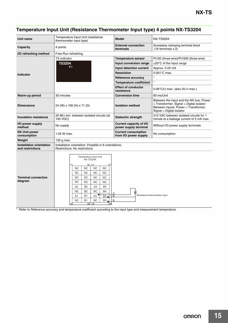
Temperature Input Unit (Resistance Thermometer Input type) 4 points NX-TS3204
* Refer to Reference accuracy and temperature coefficient according to the input type and measurement temperature.
Unit name Temperature Input Unit (resistance thermometer input type) Model NX-TS3204
Capacity 4 points External connection terminals
Screwless clamping terminal block (16 terminals x 2)
I/O refreshing method Free-Run refreshing
Indicator
TS indicator Temperature sensor Pt100 (three-wire)/Pt1000 (three-wire)
Input conversion range ±20°C of the input range
Input detection current Approx. 0.25 mA
Resolution 0.001°C max.
Reference accuracy *
Temperature coefficient *
Effect of conductor resistance 0.06°C/Ω max. (also 20 Ω max.)
Warm-up period 30 minutes Conversion time 60 ms/Unit
Dimensions 24 (W) x 100 (H) x 71 (D) Isolation method
Between the input and the NX bus: Power= Transformer, Signal = Digital isolatorBetween inputs: Power = Transformer, Signal = Digital isolator
Insulation resistance 20 MΩ min. between isolated circuits (at 100 VDC) Dielectric strength 510 VAC between isolated circuits for 1
minute at a leakage current of 5 mA max.
I/O power supply method No supply Current capacity of I/O
power supply terminal Without I/O power supply terminals
NX Unit power consumption 1.05 W max. Current consumption
from I/O power supply No consumption
Weight 130 g max.
Installation orientation and restrictions
Installation orientation: Possible in 6 orientations.Restrictions: No restrictions
Terminal connection diagram
NC NCC1 D1
C8 D8
NC NC
A4 B4
A3 B3
NC NC
NC NC
NC B4
NC B3
NC NCA1 B1
A8 B8
NC NC
A2 B2
A1 B1
NC NC
NC NC
NC B2
NC B1
ABB
Temperature Input UnitNX-TS3204
Resistance thermometer input
16
NX-TS
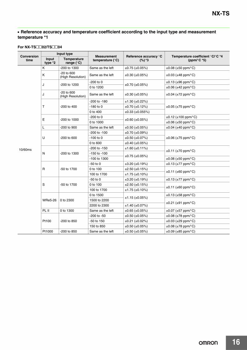
• Reference accuracy and temperature coefficient according to the input type and measurement temperature *1
For NX-TS@@02/TS@@04
Conversion time
Input typeMeasurement
temperature (°C)Reference accuracy °C
(%) *3Temperature coefficient °C/°C *4
(ppm/°C *5)Input type *2
Temperature range (°C)
10/60ms
K -200 to 1300 Same as the left ±0.75 (±0.05%) ±0.08 (±50 ppm/°C)
K -20 to 600 (High Resolution) Same as the left ±0.30 (±0.05%) ±0.03 (±48 ppm/°C)
J -200 to 1200-200 to 0
±0.70 (±0.05%)±0.13 (±96 ppm/°C)
0 to 1200 ±0.06 (±42 ppm/°C)
J -20 to 600 (High Resolution) Same as the left ±0.30 (±0.05%) ±0.04 (±72 ppm/°C)
T -200 to 400
-200 to -180 ±1.30 (±0.22%)
±0.05 (±75 ppm/°C)-180 to 0 ±0.70 (±0.12%)
0 to 400 ±0.33 (±0.055%)
E -200 to 1000-200 to 0
±0.60 (±0.05%)±0.12 (±100 ppm/°C)
0 to 1000 ±0.06 (±50 ppm/°C)
L -200 to 900 Same as the left ±0.50 (±0.05%) ±0.04 (±40 ppm/°C)
U -200 to 600
-200 to -100 ±0.70 (±0.09%)
±0.06 (±75 ppm/°C)-100 to 0 ±0.50 (±0.07%)
0 to 600 ±0.40 (±0.05%)
N -200 to 1300
-200 to -150 ±1.60 (±0.11%)±0.11 (±70 ppm/°C)
-150 to -100±0.75 (±0.05%)
-100 to 1300 ±0.08 (±50 ppm/°C)
R -50 to 1700
-50 to 0 ±3.20 (±0.19%) ±0.13 (±77 ppm/°C)
0 to 100 ±2.50 (±0.15%)±0.11 (±60 ppm/°C)
100 to 1700 ±1.75 (±0.10%)
S -50 to 1700
-50 to 0 ±3.20 (±0.19%) ±0.13 (±77 ppm/°C)
0 to 100 ±2.50 (±0.15%)±0.11 (±60 ppm/°C)
100 to 1700 ±1.75 (±0.10%)
WRe5-26 0 to 2300
0 to 1500±1.15 (±0.05%)
±0.13 (±58 ppm/°C)
1500 to 2200±0.21 (±91 ppm/°C)
2200 to 2300 ±1.40 (±0.07%)
PL II 0 to 1300 Same as the left ±0.65 (±0.05%) ±0.07 (±57 ppm/°C)
Pt100 -200 to 850
-200 to -50 ±0.50 (±0.05%) ±0.08 (±78 ppm/°C)
-50 to 150 ±0.21 (±0.02%) ±0.03 (±29 ppm/°C)
150 to 850 ±0.50 (±0.05%) ±0.08 (±78 ppm/°C)
Pt1000 -200 to 850 Same as the left ±0.50 (±0.05%) ±0.09 (±85 ppm/°C)
17
NX-TS
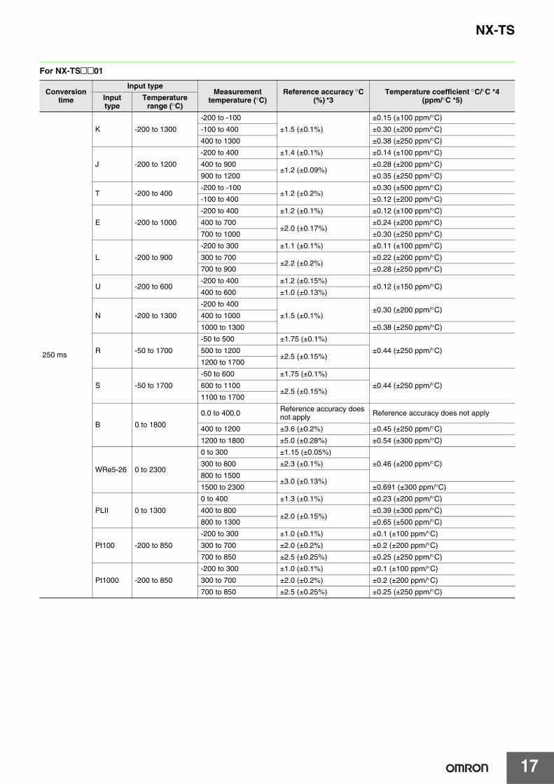
For NX-TS@@01
Conversion time
Input typeMeasurement
temperature (°C)Reference accuracy °C
(%) *3Temperature coefficient °C/°C *4
(ppm/°C *5)Input type
Temperature range (°C)
250 ms
K -200 to 1300
-200 to -100
±1.5 (±0.1%)
±0.15 (±100 ppm/°C)
-100 to 400 ±0.30 (±200 ppm/°C)
400 to 1300 ±0.38 (±250 ppm/°C)
J -200 to 1200
-200 to 400 ±1.4 (±0.1%) ±0.14 (±100 ppm/°C)
400 to 900±1.2 (±0.09%)
±0.28 (±200 ppm/°C)
900 to 1200 ±0.35 (±250 ppm/°C)
T -200 to 400-200 to -100
±1.2 (±0.2%)±0.30 (±500 ppm/°C)
-100 to 400 ±0.12 (±200 ppm/°C)
E -200 to 1000
-200 to 400 ±1.2 (±0.1%) ±0.12 (±100 ppm/°C)
400 to 700±2.0 (±0.17%)
±0.24 (±200 ppm/°C)
700 to 1000 ±0.30 (±250 ppm/°C)
L -200 to 900
-200 to 300 ±1.1 (±0.1%) ±0.11 (±100 ppm/°C)
300 to 700±2.2 (±0.2%)
±0.22 (±200 ppm/°C)
700 to 900 ±0.28 (±250 ppm/°C)
U -200 to 600-200 to 400 ±1.2 (±0.15%)
±0.12 (±150 ppm/°C)400 to 600 ±1.0 (±0.13%)
N -200 to 1300
-200 to 400
±1.5 (±0.1%)±0.30 (±200 ppm/°C)
400 to 1000
1000 to 1300 ±0.38 (±250 ppm/°C)
R -50 to 1700
-50 to 500 ±1.75 (±0.1%)
±0.44 (±250 ppm/°C)500 to 1200±2.5 (±0.15%)
1200 to 1700
S -50 to 1700
-50 to 600 ±1.75 (±0.1%)
±0.44 (±250 ppm/°C)600 to 1100±2.5 (±0.15%)
1100 to 1700
B 0 to 1800
0.0 to 400.0 Reference accuracy does not apply Reference accuracy does not apply
400 to 1200 ±3.6 (±0.2%) ±0.45 (±250 ppm/°C)
1200 to 1800 ±5.0 (±0.28%) ±0.54 (±300 ppm/°C)
WRe5-26 0 to 2300
0 to 300 ±1.15 (±0.05%)
±0.46 (±200 ppm/°C)300 to 800 ±2.3 (±0.1%)
800 to 1500±3.0 (±0.13%)
1500 to 2300 ±0.691 (±300 ppm/°C)
PLII 0 to 1300
0 to 400 ±1.3 (±0.1%) ±0.23 (±200 ppm/°C)
400 to 800±2.0 (±0.15%)
±0.39 (±300 ppm/°C)
800 to 1300 ±0.65 (±500 ppm/°C)
Pt100 -200 to 850
-200 to 300 ±1.0 (±0.1%) ±0.1 (±100 ppm/°C)
300 to 700 ±2.0 (±0.2%) ±0.2 (±200 ppm/°C)
700 to 850 ±2.5 (±0.25%) ±0.25 (±250 ppm/°C)
Pt1000 -200 to 850
-200 to 300 ±1.0 (±0.1%) ±0.1 (±100 ppm/°C)
300 to 700 ±2.0 (±0.2%) ±0.2 (±200 ppm/°C)
700 to 850 ±2.5 (±0.25%) ±0.25 (±250 ppm/°C)
18
NX-TS
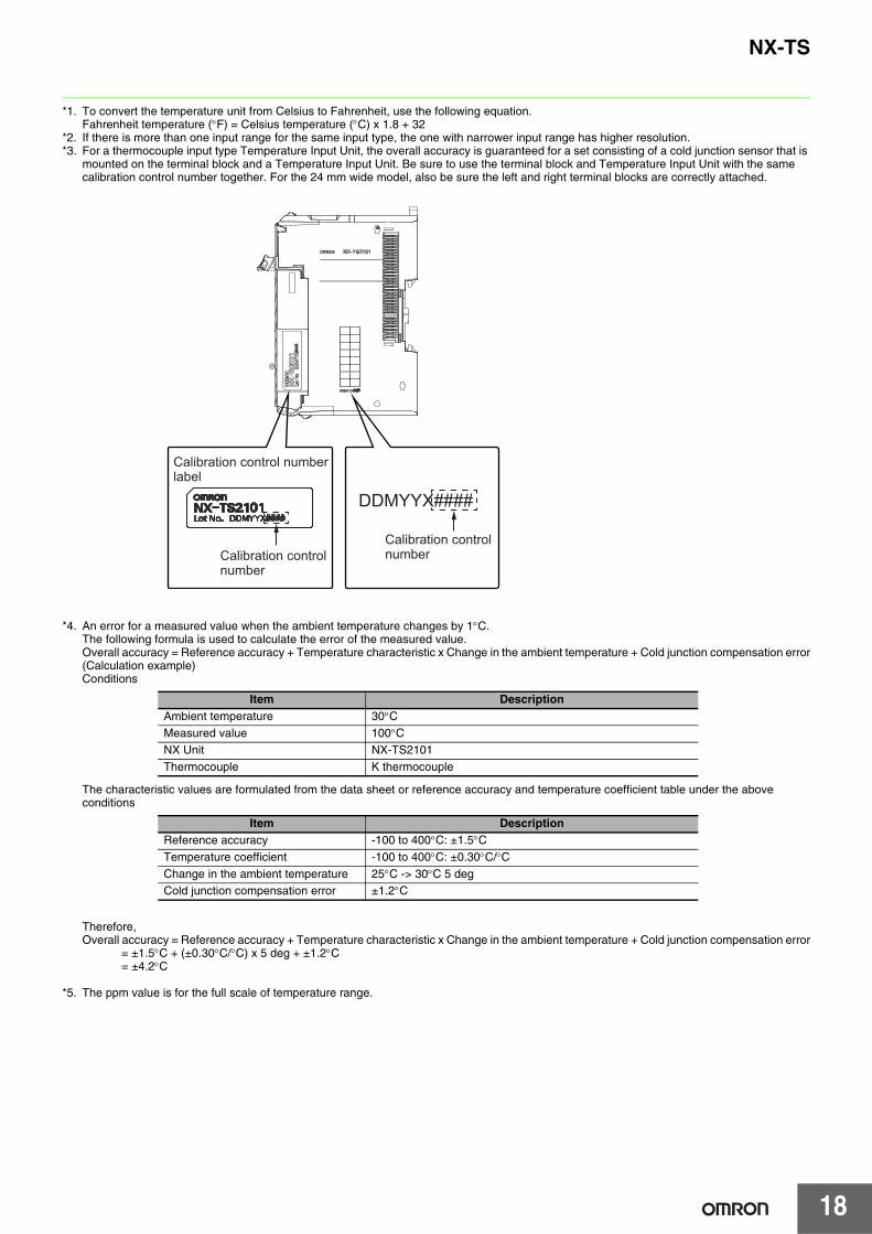
*1. To convert the temperature unit from Celsius to Fahrenheit, use the following equation.Fahrenheit temperature (°F) = Celsius temperature (°C) x 1.8 + 32
*2. If there is more than one input range for the same input type, the one with narrower input range has higher resolution.*3. For a thermocouple input type Temperature Input Unit, the overall accuracy is guaranteed for a set consisting of a cold junction sensor that is
mounted on the terminal block and a Temperature Input Unit. Be sure to use the terminal block and Temperature Input Unit with the same calibration control number together. For the 24 mm wide model, also be sure the left and right terminal blocks are correctly attached.
*4. An error for a measured value when the ambient temperature changes by 1°C.The following formula is used to calculate the error of the measured value.Overall accuracy = Reference accuracy + Temperature characteristic x Change in the ambient temperature + Cold junction compensation error(Calculation example)Conditions
The characteristic values are formulated from the data sheet or reference accuracy and temperature coefficient table under the above conditions
Therefore,Overall accuracy = Reference accuracy + Temperature characteristic x Change in the ambient temperature + Cold junction compensation error = ±1.5°C + (±0.30°C/°C) x 5 deg + ±1.2°C = ±4.2°C
*5. The ppm value is for the full scale of temperature range.
Item DescriptionAmbient temperature 30°CMeasured value 100°CNX Unit NX-TS2101Thermocouple K thermocouple
Item DescriptionReference accuracy -100 to 400°C: ±1.5°CTemperature coefficient -100 to 400°C: ±0.30°C/°CChange in the ambient temperature 25°C -> 30°C 5 degCold junction compensation error ±1.2°C
DDMYYX####
Calibration control numberlabel
Calibration controlnumber
Calibration controlnumber
19
NX-TS
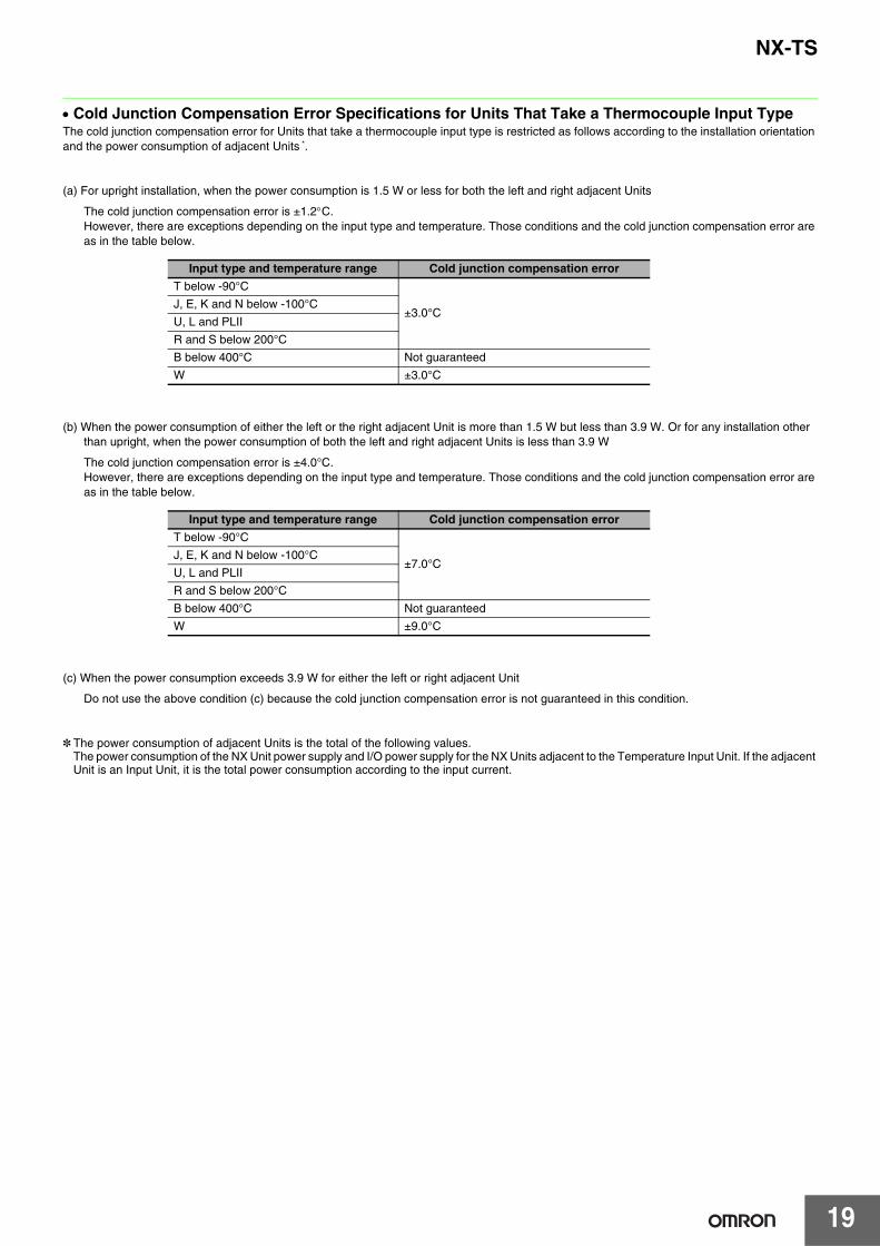
• Cold Junction Compensation Error Specifications for Units That Take a Thermocouple Input TypeThe cold junction compensation error for Units that take a thermocouple input type is restricted as follows according to the installation orientation and the power consumption of adjacent Units *.
(a) For upright installation, when the power consumption is 1.5 W or less for both the left and right adjacent Units
The cold junction compensation error is ±1.2°C.However, there are exceptions depending on the input type and temperature. Those conditions and the cold junction compensation error are as in the table below.
(b) When the power consumption of either the left or the right adjacent Unit is more than 1.5 W but less than 3.9 W. Or for any installation other than upright, when the power consumption of both the left and right adjacent Units is less than 3.9 W
The cold junction compensation error is ±4.0°C.However, there are exceptions depending on the input type and temperature. Those conditions and the cold junction compensation error are as in the table below.
(c) When the power consumption exceeds 3.9 W for either the left or right adjacent Unit
Do not use the above condition (c) because the cold junction compensation error is not guaranteed in this condition.
* The power consumption of adjacent Units is the total of the following values.The power consumption of the NX Unit power supply and I/O power supply for the NX Units adjacent to the Temperature Input Unit. If the adjacent Unit is an Input Unit, it is the total power consumption according to the input current.
Input type and temperature range Cold junction compensation error
T below -90°C
±3.0°CJ, E, K and N below -100°C
U, L and PLII
R and S below 200°C
B below 400°C Not guaranteed
W ±3.0°C
Input type and temperature range Cold junction compensation error
T below -90°C
±7.0°CJ, E, K and N below -100°C
U, L and PLII
R and S below 200°C
B below 400°C Not guaranteed
W ±9.0°C
NX-TS
20
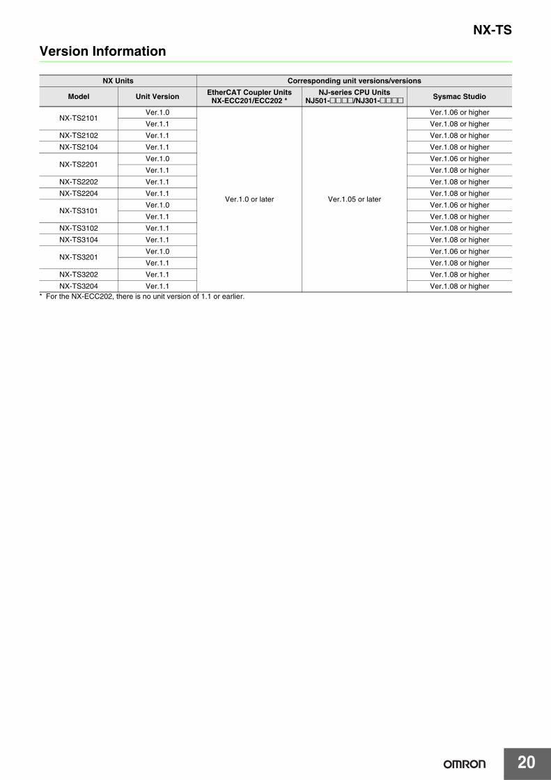
Version Information
* For the NX-ECC202, there is no unit version of 1.1 or earlier.
NX Units Corresponding unit versions/versions
Model Unit Version EtherCAT Coupler Units NX-ECC201/ECC202 *
NJ-series CPU UnitsNJ501-@@@@/NJ301-@@@@ Sysmac Studio
NX-TS2101Ver.1.0
Ver.1.0 or later Ver.1.05 or later
Ver.1.06 or higher
Ver.1.1 Ver.1.08 or higher
NX-TS2102 Ver.1.1 Ver.1.08 or higher
NX-TS2104 Ver.1.1 Ver.1.08 or higher
NX-TS2201 Ver.1.0 Ver.1.06 or higher
Ver.1.1 Ver.1.08 or higher
NX-TS2202 Ver.1.1 Ver.1.08 or higher
NX-TS2204 Ver.1.1 Ver.1.08 or higher
NX-TS3101 Ver.1.0 Ver.1.06 or higher
Ver.1.1 Ver.1.08 or higher
NX-TS3102 Ver.1.1 Ver.1.08 or higher
NX-TS3104 Ver.1.1 Ver.1.08 or higher
NX-TS3201Ver.1.0 Ver.1.06 or higher
Ver.1.1 Ver.1.08 or higher
NX-TS3202 Ver.1.1 Ver.1.08 or higher
NX-TS3204 Ver.1.1 Ver.1.08 or higher
21
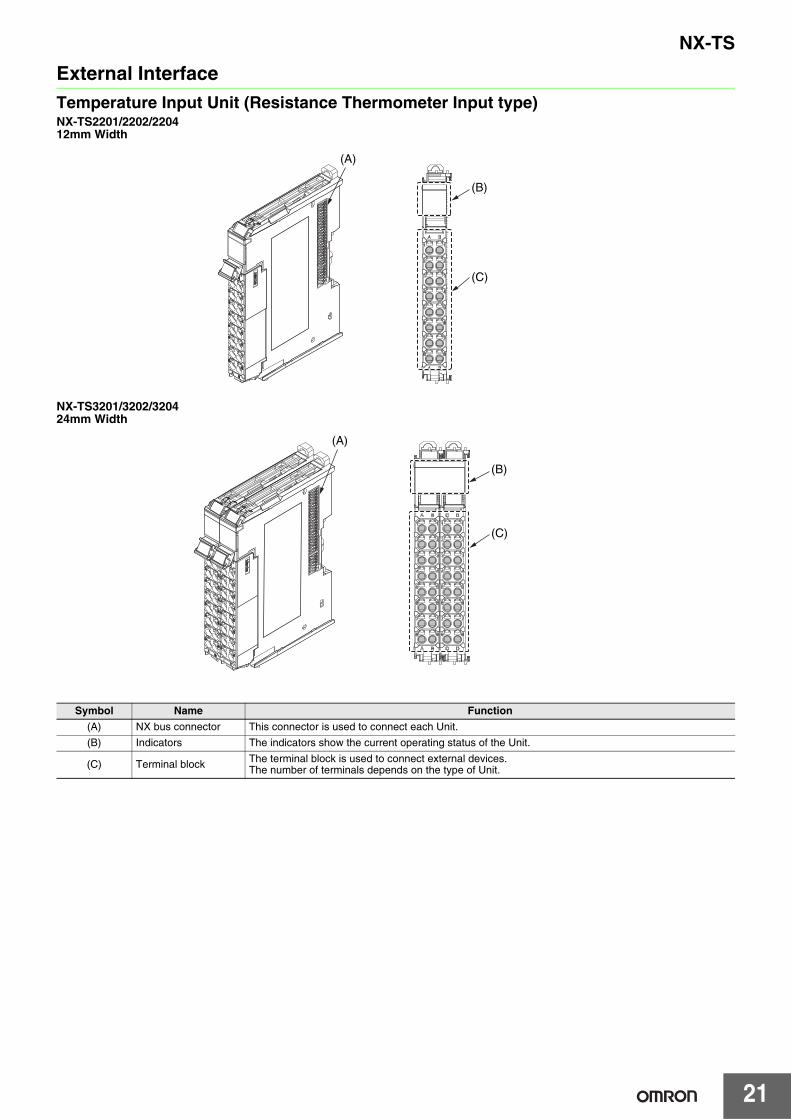
NX-TS
External InterfaceTemperature Input Unit (Resistance Thermometer Input type)NX-TS2201/2202/220412mm Width
NX-TS3201/3202/320424mm Width
Symbol Name Function
(A) NX bus connector This connector is used to connect each Unit.
(B) Indicators The indicators show the current operating status of the Unit.
(C) Terminal block The terminal block is used to connect external devices.The number of terminals depends on the type of Unit.
(C)
(B)
(A)
(A)
(C)
(B)
NX-TS
22
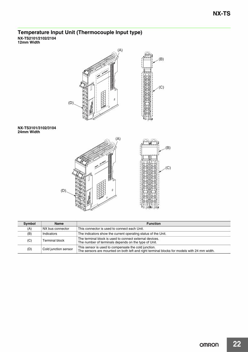
Temperature Input Unit (Thermocouple Input type)NX-TS2101/2102/210412mm Width
NX-TS3101/3102/310424mm Width
Symbol Name Function
(A) NX bus connector This connector is used to connect each Unit.
(B) Indicators The indicators show the current operating status of the Unit.
(C) Terminal block The terminal block is used to connect external devices.The number of terminals depends on the type of Unit.
(D) Cold junction sensor This sensor is used to compensate the cold junction.The sensors are mounted on both left and right terminal blocks for models with 24 mm width.
(C)
(B)
(A)
(D)
(A)
(C)
(B)
(D)
23
NX-TS
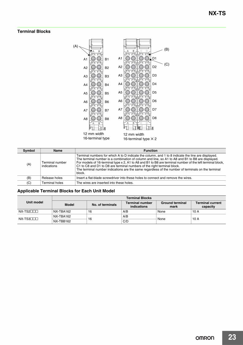
Terminal Blocks
Applicable Terminal Blocks for Each Unit Model
Symbol Name Function
(A) Terminal number indications
Terminal numbers for which A to D indicate the column, and 1 to 8 indicate the line are displayed.The terminal number is a combination of column and line, so A1 to A8 and B1 to B8 are displayed.For models of 16-terminal type x 2, A1 to A8 and B1 to B8 are terminal number of the left terminal block, C1 to C8 and D1 to D8 are terminal numbers of the right terminal block.The terminal number indications are the same regardless of the number of terminals on the terminal block.
(B) Release holes Insert a flat-blade screwdriver into these holes to connect and remove the wires.
(C) Terminal holes The wires are inserted into these holes.
Unit modelTerminal Blocks
Model No. of terminals Terminal number indications
Ground terminal mark
Terminal current capacity
NX-TS2@@@ NX-TBA162 16 A/B None 10 A
NX-TS3@@@NX-TBA162
16A/B
None 10 ANX-TBB162 C/D
(B)
(C)
A1
A2
A3
A4
A5
A6
A7
A8
D1
D2
D3
D4
D5
D6
D7
D8
A1
A2
A3
A4
A5
A6
A7
A8
B1
B2
B3
B4
B5
B6
B7
B8
(A)C D
C D
12 mm width16-terminal type
12 mm width16-terminal type ✕ 2
24
NX-TS
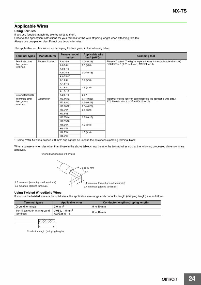
Applicable WiresUsing FerrulesIf you use ferrules, attach the twisted wires to them.Observe the application instructions for your ferrules for the wire stripping length when attaching ferrules.Always use one-pin ferrules. Do not use two-pin ferrules.
The applicable ferrules, wires, and crimping tool are given in the following table.
* Some AWG 14 wires exceed 2.0 mm2 and cannot be used in the screwless clamping terminal block.
When you use any ferrules other than those in the above table, crimp them to the twisted wires so that the following processed dimensions are achieved.
Using Twisted Wires/Solid WiresIf you use the twisted wires or the solid wires, the applicable wire range and conductor length (stripping length) are as follows.
Terminal types Manufacturer Ferrule modelnumber
Applicable wire(mm2 (AWG)) Crimping tool
Terminals other than ground terminals
Phoenix Contact AI0,34-8 0.34 (#22) Phoenix Contact (The figure in parentheses is the applicable wire size.)CRIMPFOX 6 (0.25 to 6 mm2, AWG24 to 10)AI0,5-8 0.5 (#20)
AI0,5-10
AI0,75-8 0.75 (#18)
AI0,75-10
AI1,0-8 1.0 (#18)
AI1,0-10
AI1,5-8 1.5 (#16)
AI1,5-10
Ground terminals AI2,5-10 2.0 *
Terminals other than ground terminals
Weidmuller H0.14/12 0.14 (#26) Weidmuller (The figure in parentheses is the applicable wire size.)PZ6 Roto (0.14 to 6 mm2, AWG 26 to 10)H0.25/12 0.25 (#24)
H0.34/12 0.34 (#22)
H0.5/14 0.5 (#20)
H0.5/16
H0.75/14 0.75 (#18)
H0.75/16
H1.0/14 1.0 (#18)
H1.0/16
H1.5/14 1.5 (#16)
H1.5/16
Terminal types Applicable wires Conductor length (stripping length)
Ground terminals 2.0 mm2 9 to 10 mm
Terminals other than ground terminals
0.08 to 1.5 mm2
AWG28 to 16 8 to 10 mm
Finished Dimensions of Ferrules
1.6 mm max. (except ground terminals)2.0 mm max. (ground terminals)
2.4 mm max. (except ground terminals)2.7 mm max. (ground terminals)
8 to 10 mm
Conductor length (stripping length)
25
NX-TS
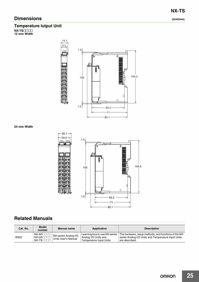
Dimensions (Unit/mm)
Temperature Iutput Unit NX-TS@@@@12 mm Width
24 mm Width
Related Manuals
Cat. No. Model number Manual name Application Description
W522NX-AD@@@@NX-DA@@@@NX-TS@@@@
NX-series Analog I/O Units User’s Manual
Learning how to use NX-series Analog I/O Units and Temperature Input Units
The hardware, setup methods, and functions of the NX-series Analog I/O Units and Temperature Input Units are described.
80.1
71
104.5100
14.1
65.2
12.0
1.5
1.5
C D
C D
26.1
24.0
80.1
71
104.5100
65.21.5
1.5
Terms and Conditions of Sale1. Offer; Acceptance. These terms and conditions (these "Terms") are deemed
part of all quotes, agreements, purchase orders, acknowledgments, price lists,catalogs, manuals, brochures and other documents, whether electronic or inwriting, relating to the sale of products or services (collectively, the "Products")by Omron Electronics LLC and its subsidiary companies (“Omron”). Omronobjects to any terms or conditions proposed in Buyer’s purchase order or otherdocuments which are inconsistent with, or in addition to, these Terms.
2. Prices; Payment Terms. All prices stated are current, subject to change with-out notice by Omron. Omron reserves the right to increase or decrease priceson any unshipped portions of outstanding orders. Payments for Products aredue net 30 days unless otherwise stated in the invoice.
3. Discounts. Cash discounts, if any, will apply only on the net amount of invoicessent to Buyer after deducting transportation charges, taxes and duties, and willbe allowed only if (i) the invoice is paid according to Omron’s payment termsand (ii) Buyer has no past due amounts.
4. Interest. Omron, at its option, may charge Buyer 1-1/2% interest per month orthe maximum legal rate, whichever is less, on any balance not paid within thestated terms.
5. Orders. Omron will accept no order less than $200 net billing. 6. Governmental Approvals. Buyer shall be responsible for, and shall bear all
costs involved in, obtaining any government approvals required for the impor-tation or sale of the Products.
7. Taxes. All taxes, duties and other governmental charges (other than generalreal property and income taxes), including any interest or penalties thereon,imposed directly or indirectly on Omron or required to be collected directly orindirectly by Omron for the manufacture, production, sale, delivery, importa-tion, consumption or use of the Products sold hereunder (including customsduties and sales, excise, use, turnover and license taxes) shall be charged toand remitted by Buyer to Omron.
8. Financial. If the financial position of Buyer at any time becomes unsatisfactoryto Omron, Omron reserves the right to stop shipments or require satisfactorysecurity or payment in advance. If Buyer fails to make payment or otherwisecomply with these Terms or any related agreement, Omron may (without liabil-ity and in addition to other remedies) cancel any unshipped portion of Prod-ucts sold hereunder and stop any Products in transit until Buyer pays allamounts, including amounts payable hereunder, whether or not then due,which are owing to it by Buyer. Buyer shall in any event remain liable for allunpaid accounts.
9. Cancellation; Etc. Orders are not subject to rescheduling or cancellationunless Buyer indemnifies Omron against all related costs or expenses.
10. Force Majeure. Omron shall not be liable for any delay or failure in deliveryresulting from causes beyond its control, including earthquakes, fires, floods,strikes or other labor disputes, shortage of labor or materials, accidents tomachinery, acts of sabotage, riots, delay in or lack of transportation or therequirements of any government authority.
11. Shipping; Delivery. Unless otherwise expressly agreed in writing by Omron:a. Shipments shall be by a carrier selected by Omron; Omron will not drop ship
except in “break down” situations.b. Such carrier shall act as the agent of Buyer and delivery to such carrier shall
constitute delivery to Buyer;c. All sales and shipments of Products shall be FOB shipping point (unless oth-
erwise stated in writing by Omron), at which point title and risk of loss shallpass from Omron to Buyer; provided that Omron shall retain a security inter-est in the Products until the full purchase price is paid;
d. Delivery and shipping dates are estimates only; ande. Omron will package Products as it deems proper for protection against nor-
mal handling and extra charges apply to special conditions.12. Claims. Any claim by Buyer against Omron for shortage or damage to the
Products occurring before delivery to the carrier must be presented in writingto Omron within 30 days of receipt of shipment and include the original trans-portation bill signed by the carrier noting that the carrier received the Productsfrom Omron in the condition claimed.
13. Warranties. (a) Exclusive Warranty. Omron’s exclusive warranty is that theProducts will be free from defects in materials and workmanship for a period oftwelve months from the date of sale by Omron (or such other period expressedin writing by Omron). Omron disclaims all other warranties, express or implied.(b) Limitations. OMRON MAKES NO WARRANTY OR REPRESENTATION,EXPRESS OR IMPLIED, ABOUT NON-INFRINGEMENT, MERCHANTABIL-
ITY OR FITNESS FOR A PARTICULAR PURPOSE OF THE PRODUCTS.BUYER ACKNOWLEDGES THAT IT ALONE HAS DETERMINED THAT THEPRODUCTS WILL SUITABLY MEET THE REQUIREMENTS OF THEIRINTENDED USE. Omron further disclaims all warranties and responsibility ofany type for claims or expenses based on infringement by the Products or oth-erwise of any intellectual property right. (c) Buyer Remedy. Omron’s sole obli-gation hereunder shall be, at Omron’s election, to (i) replace (in the formoriginally shipped with Buyer responsible for labor charges for removal orreplacement thereof) the non-complying Product, (ii) repair the non-complyingProduct, or (iii) repay or credit Buyer an amount equal to the purchase price ofthe non-complying Product; provided that in no event shall Omron be responsi-ble for warranty, repair, indemnity or any other claims or expenses regardingthe Products unless Omron’s analysis confirms that the Products were prop-erly handled, stored, installed and maintained and not subject to contamina-tion, abuse, misuse or inappropriate modification. Return of any Products byBuyer must be approved in writing by Omron before shipment. Omron Compa-nies shall not be liable for the suitability or unsuitability or the results from theuse of Products in combination with any electrical or electronic components,circuits, system assemblies or any other materials or substances or environ-ments. Any advice, recommendations or information given orally or in writing,are not to be construed as an amendment or addition to the above warranty.See http://www.omron247.com or contact your Omron representative for pub-lished information.
14. Limitation on Liability; Etc. OMRON COMPANIES SHALL NOT BE LIABLEFOR SPECIAL, INDIRECT, INCIDENTAL, OR CONSEQUENTIAL DAMAGES,LOSS OF PROFITS OR PRODUCTION OR COMMERCIAL LOSS IN ANYWAY CONNECTED WITH THE PRODUCTS, WHETHER SUCH CLAIM ISBASED IN CONTRACT, WARRANTY, NEGLIGENCE OR STRICT LIABILITY.Further, in no event shall liability of Omron Companies exceed the individualprice of the Product on which liability is asserted.
15. Indemnities. Buyer shall indemnify and hold harmless Omron Companies andtheir employees from and against all liabilities, losses, claims, costs andexpenses (including attorney's fees and expenses) related to any claim, inves-tigation, litigation or proceeding (whether or not Omron is a party) which arisesor is alleged to arise from Buyer's acts or omissions under these Terms or inany way with respect to the Products. Without limiting the foregoing, Buyer (atits own expense) shall indemnify and hold harmless Omron and defend or set-tle any action brought against such Companies to the extent based on a claimthat any Product made to Buyer specifications infringed intellectual propertyrights of another party.
16. Property; Confidentiality. Any intellectual property in the Products is the exclu-sive property of Omron Companies and Buyer shall not attempt to duplicate itin any way without the written permission of Omron. Notwithstanding anycharges to Buyer for engineering or tooling, all engineering and tooling shallremain the exclusive property of Omron. All information and materials suppliedby Omron to Buyer relating to the Products are confidential and proprietary,and Buyer shall limit distribution thereof to its trusted employees and strictlyprevent disclosure to any third party.
17. Export Controls. Buyer shall comply with all applicable laws, regulations andlicenses regarding (i) export of products or information; (iii) sale of products to“forbidden” or other proscribed persons; and (ii) disclosure to non-citizens ofregulated technology or information.
18. Miscellaneous. (a) Waiver. No failure or delay by Omron in exercising any rightand no course of dealing between Buyer and Omron shall operate as a waiverof rights by Omron. (b) Assignment. Buyer may not assign its rights hereunderwithout Omron's written consent. (c) Law. These Terms are governed by thelaw of the jurisdiction of the home office of the Omron company from whichBuyer is purchasing the Products (without regard to conflict of law princi-ples). (d) Amendment. These Terms constitute the entire agreement betweenBuyer and Omron relating to the Products, and no provision may be changedor waived unless in writing signed by the parties. (e) Severability. If any provi-sion hereof is rendered ineffective or invalid, such provision shall not invalidateany other provision. (f) Setoff. Buyer shall have no right to set off any amountsagainst the amount owing in respect of this invoice. (g) Definitions. As usedherein, “including” means “including without limitation”; and “Omron Compa-nies” (or similar words) mean Omron Corporation and any direct or indirectsubsidiary or affiliate thereof.
Certain Precautions on Specifications and Use1. Suitability of Use. Omron Companies shall not be responsible for conformity
with any standards, codes or regulations which apply to the combination of theProduct in the Buyer’s application or use of the Product. At Buyer’s request,Omron will provide applicable third party certification documents identifyingratings and limitations of use which apply to the Product. This information byitself is not sufficient for a complete determination of the suitability of the Prod-uct in combination with the end product, machine, system, or other applicationor use. Buyer shall be solely responsible for determining appropriateness ofthe particular Product with respect to Buyer’s application, product or system.Buyer shall take application responsibility in all cases but the following is anon-exhaustive list of applications for which particular attention must be given:(i) Outdoor use, uses involving potential chemical contamination or electricalinterference, or conditions or uses not described in this document.(ii) Use in consumer products or any use in significant quantities. (iii) Energy control systems, combustion systems, railroad systems, aviationsystems, medical equipment, amusement machines, vehicles, safety equip-ment, and installations subject to separate industry or government regulations. (iv) Systems, machines and equipment that could present a risk to life or prop-erty. Please know and observe all prohibitions of use applicable to this Prod-uct. NEVER USE THE PRODUCT FOR AN APPLICATION INVOLVING SERIOUSRISK TO LIFE OR PROPERTY OR IN LARGE QUANTITIES WITHOUTENSURING THAT THE SYSTEM AS A WHOLE HAS BEEN DESIGNED TO
ADDRESS THE RISKS, AND THAT THE OMRON’S PRODUCT IS PROP-ERLY RATED AND INSTALLED FOR THE INTENDED USE WITHIN THEOVERALL EQUIPMENT OR SYSTEM.
2. Programmable Products. Omron Companies shall not be responsible for theuser’s programming of a programmable Product, or any consequence thereof.
3. Performance Data. Data presented in Omron Company websites, catalogsand other materials is provided as a guide for the user in determining suitabil-ity and does not constitute a warranty. It may represent the result of Omron’stest conditions, and the user must correlate it to actual application require-ments. Actual performance is subject to the Omron’s Warranty and Limitationsof Liability.
4. Change in Specifications. Product specifications and accessories may bechanged at any time based on improvements and other reasons. It is our prac-tice to change part numbers when published ratings or features are changed,or when significant construction changes are made. However, some specifica-tions of the Product may be changed without any notice. When in doubt, spe-cial part numbers may be assigned to fix or establish key specifications foryour application. Please consult with your Omron’s representative at any timeto confirm actual specifications of purchased Product.
5. Errors and Omissions. Information presented by Omron Companies has beenchecked and is believed to be accurate; however, no responsibility is assumedfor clerical, typographical or proofreading errors or omissions.
OMRON CANADA, INC. • HEAD OFFICEToronto, ON, Canada • 416.286.6465 • 866.986.6766 • www.omron247.com
OMRON ELECTRONICS DE MEXICO • HEAD OFFICEMéxico DF • 52.55.59.01.43.00 • 01-800-226-6766 • [email protected]
OMRON ELECTRONICS DE MEXICO • SALES OFFICEApodaca, N.L. • 52.81.11.56.99.20 • 01-800-226-6766 • [email protected]
OMRON ELETRÔNICA DO BRASIL LTDA • HEAD OFFICESão Paulo, SP, Brasil • 55.11.2101.6300 • www.omron.com.br
OMRON ARGENTINA • SALES OFFICECono Sur • 54.11.4783.5300
OMRON CHILE • SALES OFFICESantiago • 56.9.9917.3920
OTHER OMRON LATIN AMERICA SALES54.11.4783.5300
Authorized Distributor:
04/14 Note: Specifications are subject to change. © 2014 Omron Electronics LLC Printed in U.S.A.
Printed on recycled paper.
Automation Control Systems• Machine Automation Controllers (MAC) • Programmable Controllers (PLC) • Operator interfaces (HMI) • Distributed I/O • Software
Drives & Motion Controls • Servo & AC Drives • Motion Controllers & Encoders
Temperature & Process Controllers • Single and Multi-loop Controllers
Sensors & Vision• Proximity Sensors • Photoelectric Sensors • Fiber-Optic Sensors• Amplified Photomicrosensors • Measurement Sensors• Ultrasonic Sensors • Vision Sensors
Industrial Components • RFID/Code Readers • Relays • Pushbuttons & Indicators • Limit and Basic Switches • Timers • Counters • Metering Devices • Power Supplies
Safety • Laser Scanners • Safety Mats • Edges and Bumpers • Programmable Safety Controllers • Light Curtains • Safety Relays • Safety Interlock Switches
OMRON AUTOMATION AND SAFETY • THE AMERICAS HEADQUARTERS • Chicago, IL USA • 847.843.7900 • 800.556.6766 • www.omron247.com
OMRON EUROPE B.V. • Wegalaan 67-69, NL-2132 JD, Hoofddorp, The Netherlands. • +31 (0) 23 568 13 00 • www.industrial.omron.eu


![NX post processor [NX CAM]](https://static.fdocuments.in/doc/165x107/588910c81a28ab4a5c8b59e9/nx-post-processor-nx-cam.jpg)