
NW2 Duplex -GRAVITY VIBRATOR Manual
38
NW2 EAGLE NET WEIGH BAGGING SCALE JEM INTERNATIONAL, INC. 6873 MARTINDALE SHAWNEE, KS 66218 Phone: (913) 441‐4788 FAX: 913‐441‐1711 www.JemBaggingScales.com Email: [email protected]
Transcript of NW2 Duplex -GRAVITY VIBRATOR Manual

NW2 EAGLE NET WEIGH BAGGING SCALE
JEM INTERNATIONAL, INC. 6873 MARTINDALE SHAWNEE, KS 66218
Phone: (913) 441‐4788 FAX: 913‐441‐1711 www.JemBaggingScales.com Email: [email protected]

RECEIVING THE SCALE
The scale in most instances is shipped in a wooden crate. If the scale has the following feeders, typically the parts of each shipment are as follows:
Gravity Gate 2-position
One scale assembly with gravity gate attached One spout assembly unattached One process controller panel
Single Vibratory (2-speed feed rate) One scale assembly One vibrator assembly One control panel for vibratory feeder One spout assembly unattached One digital control panel for scale
Gravity Gate/Vibratory Feeder One scale assembly with gravity gate attached One spout assembly unattached One digital control panel unattached One vibrating pan feeder and framework unattached One pant leg diverter unattached
Belt 2-Position pneumatic flow gate or Variable Speed Controller (2-speed feed rate) One scale assembly with feeder attached One spout assembly unattached One digital control panel unattached One drip pan unattached
Twin Auger Variable Speed Controller One scale assembly and slide gate attached One Auger feeder unattached One spout assembly unattached One digital control panel unattached
Check the condition of the scale, as it arrives from the shipping company. It is extremely important that if damage is noted, a freight claim is filed by your company at this point. The shipper cannot file a freight claim on your behalf and it is imperative that before the scale system is removed from the crate that it be inspected thoroughly.
DIGITAL INSTRUCTION MANUAL
The scale preweighs the product prior to discharging it into the bag. The typical model is designed for handling 10-14, 50 lb. (25 kg.) bags per minute at () 2 oz. to 3 oz accuracy (55 to 85 grams) at 2 Sigma (95%).
The scale can be supplied in simplex, duplex or triplex operation. The scale has 3 sections:
1) The Feeder Section is the section most associated with weight accuracy.
The feeder section can be one of the following designs: Gravity Gate (2 position) Gravity Gate/Vibratory Feeder Single Vibratory (2-speed feed rate) Belt 2 Position Pneumatic Flow Gate or Variable Speed Controller
(2 Speed feed rate) Twin Auger Variable Speed Controller
The feeder is chosen based on product flow characteristics. All scales are designed with 2-speed feed rates, both fast and slow fill. Typically the slow or dribble fill should be set for no greater than 5 lbs. (2 ½ kg.) per second fill rate.
2) The Center Section of the scale is where the actual weighing is accomplished. The weighing is
accomplished in a weigh hopper supplied with double door design. The weigh hopper is available in 2 cubic foot, 3 ½ cubic foot and 4 cubic foot as standard. The size of the weigh hopper is determined by the bulk density of your product and the target weight. The center section also includes the complete pneumatic filter regulator assembly and the weighing load cells and valves. This section also includes a transition to connect up to a bag clamp assembly or into other automated equipment.
3) The spout is designed for holding the bag in place during the discharge cycle. The spout can be
supplied in either air operated dust tight design with a 21”, 25”, or 31” (52, 62, or 77 cm.) circumference spout as standard. We also have a clam shell design spout which is designed to work on bags with a larger than 28” (70 cm.) circumference. Only one clam shell size spout is available, and is typically used in non-dusty applications.
The scale can be operated with either a pneumatic foot pedal or a hand switch on the spout assembly.
PLANNING THE INSTALLATION
The scale should be installed with the bottom of the spout typically 48” (1.2 meters) from floor level. This is typically ideal height for the operator to work at. If the scale is being supplied with an automatic bag placer, check the prints to verify dimensions for installation.
The 48” (1.2 meters) is divided by a maximum bag height of 36” (.9 meters) and 12” (.3 meters) for the conveyor. If the bag is shorter than 36” (.9 meters), the height of the conveyor is typically raised to suit. If, however, the bag is taller than 36” (.9 meters), the height of the scale will have to be adjusted accordingly. The process controller needs to be positioned in an area easily accessible by the operator of the scale. The operator must be able to visually see the digital display and be capable of touching the panel to make adjustments.
The scale is supplied with a filter regulator system for receiving air. A ¼” male quick connect pipe connection is supplied on the scale. The scale will require 100 PSI air pressure at 4 cubic feet per minute on a simplex and 7 to 8 cubic feet per minute on a duplex.
There are two filter regulators on each scale. The upper unit is designed for handling the pneumatic needs of the feeder section and the weigh hopper. The lower unit is designed for handling the complete pneumatic needs of the bag clamp assembly.
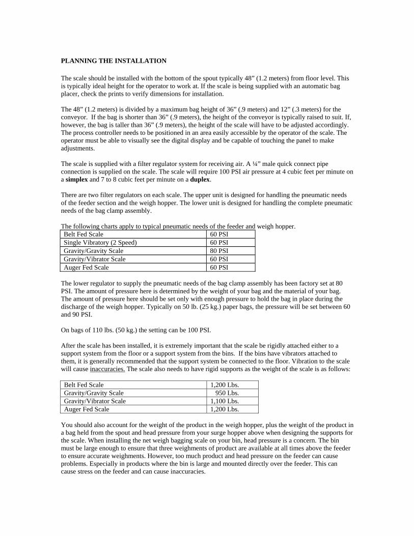
The following charts apply to typical pneumatic needs of the feeder and weigh hopper. Belt Fed Scale 60 PSI Single Vibratory (2 Speed) 60 PSI Gravity/Gravity Scale 80 PSI Gravity/Vibrator Scale 60 PSI Auger Fed Scale 60 PSI
The lower regulator to supply the pneumatic needs of the bag clamp assembly has been factory set at 80 PSI. The amount of pressure here is determined by the weight of your bag and the material of your bag. The amount of pressure here should be set only with enough pressure to hold the bag in place during the discharge of the weigh hopper. Typically on 50 lb. (25 kg.) paper bags, the pressure will be set between 60 and 90 PSI.
On bags of 110 lbs. (50 kg.) the setting can be 100 PSI.
After the scale has been installed, it is extremely important that the scale be rigidly attached either to a support system from the floor or a support system from the bins. If the bins have vibrators attached to them, it is generally recommended that the support system be connected to the floor. Vibration to the scale will cause inaccuracies. The scale also needs to have rigid supports as the weight of the scale is as follows:
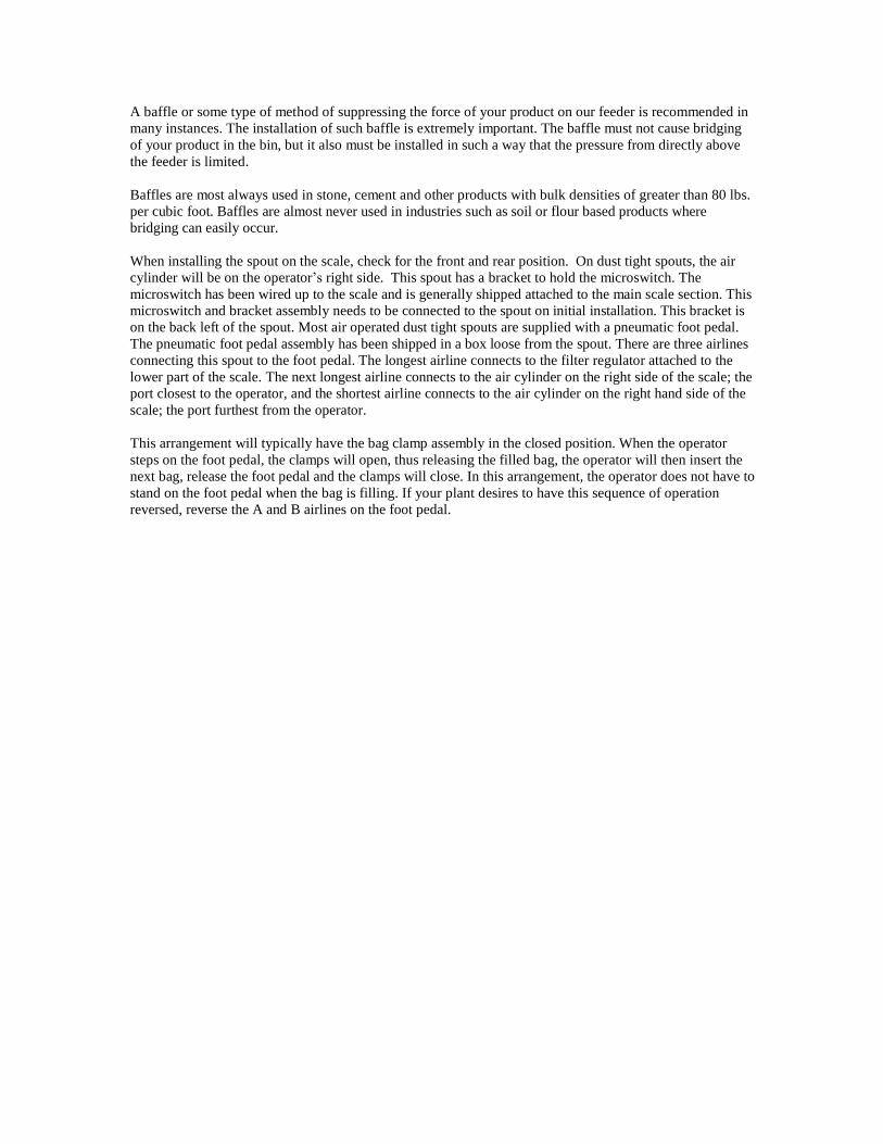
Belt Fed Scale 1,200 Lbs. Gravity/Gravity Scale 950 Lbs. Gravity/Vibrator Scale 1,100 Lbs. Auger Fed Scale 1,200 Lbs.
You should also account for the weight of the product in the weigh hopper, plus the weight of the product in a bag held from the spout and head pressure from your surge hopper above when designing the supports for the scale. When installing the net weigh bagging scale on your bin, head pressure is a concern. The bin must be large enough to ensure that three weighments of product are available at all times above the feeder to ensure accurate weighments. However, too much product and head pressure on the feeder can cause problems. Especially in products where the bin is large and mounted directly over the feeder. This can cause stress on the feeder and can cause inaccuracies.
A baffle or some type of method of suppressing the force of your product on our feeder is recommended in
many instances. The installation of such baffle is extremely important. The baffle must not cause bridging
of your product in the bin, but it also must be installed in such a way that the pressure from directly above
the feeder is limited.
Baffles are most always used in stone, cement and other products with bulk densities of greater than 80 lbs.
per cubic foot. Baffles are almost never used in industries such as soil or flour based products where
bridging can easily occur.
When installing the spout on the scale, check for the front and rear position. On dust tight spouts, the air
cylinder will be on the operator’s right side. This spout has a bracket to hold the microswitch. The
microswitch has been wired up to the scale and is generally shipped attached to the main scale section. This
microswitch and bracket assembly needs to be connected to the spout on initial installation. This bracket is
on the back left of the spout. Most air operated dust tight spouts are supplied with a pneumatic foot pedal.
The pneumatic foot pedal assembly has been shipped in a box loose from the spout. There are three airlines
connecting this spout to the foot pedal. The longest airline connects to the filter regulator attached to the
lower part of the scale. The next longest airline connects to the air cylinder on the right side of the scale; the
port closest to the operator, and the shortest airline connects to the air cylinder on the right hand side of the
scale; the port furthest from the operator.
This arrangement will typically have the bag clamp assembly in the closed position. When the operator
steps on the foot pedal, the clamps will open, thus releasing the filled bag, the operator will then insert the
next bag, release the foot pedal and the clamps will close. In this arrangement, the operator does not have to
stand on the foot pedal when the bag is filling. If your plant desires to have this sequence of operation
reversed, reverse the A and B airlines on the foot pedal.

ELECTRICAL INSTALLATION
Please see included wiring schematic for installation. The main scale assembly on the scale has a terminal strip with
numbers. The controller was disconnected for shipping purposes. The controller has been prewired with connection
cables. Please follow the schematic for matching color codes for wire terminating to bagging scale. The load cell
cable, control wire and power cord will all arrive connected.
The controller (duplex or triplex scales) has a terminal strip with numbers/letters. These need to be matched to the
same numbers/letters on the terminal strip at the scale housing. You will need to provide control wire for the
connections. Please do not use anything less than 16 AWG stranded wire. Please see local electrical codes for length
of run and AWG specifications. The load cell cable is connected within the controller and includes 15 feet to
connect to the summing box on the bagging scale.
Please do not run high voltage (90 VAC or higher) in the same conduit as the low voltage control wire. You can
either run this in the same conduit as the load cell cable or provide its own separate conduit. A pre-punched hole is
included for incoming power, control wire and load cell cable (3 total).
The load cells have cable connecting into a common load cell summing box. This load cell summing box needs to
connect to the bottom of the controller.
It is extremely important to remember that load cell cable and wire cannot be run in the same conduit. You must run
one conduit for the wire and a separate conduit for the load cell cable or else there is a possibility of line interference
to the load cells causing weight inaccuracies.
The programmable controller is designed to work with a clean grounded isolated 110 volt supply, an amp fuse is
provided. In foreign installations where 220 volt is available, a step down transformer has been supplied in the
control panel to transform from 220 volt to 110 voltage
If the scale is supplied with an auger or belt feeder without variable speed drive, then the 3 phase power is connected
to the terminal strip mounted on the scale. This terminal strip is marked L1, L2 and L3 (see attached schematic).
All motors have been clearly marked with their voltage requirements. Verify all this prior to installing 3 phase
power. On 110 v connections to control panel it is extremely important that this voltage be verified before being
introduced to the scale system. The incoming 110 v power should be connected to L and N on the terminal strip.
Verify we have a clean neutral that no voltage is present between ground and neutral. Ground to L should be 110 V
() 15%.

Photo 1
Load cell cover
Hopper support bracket
Gap
1/4”
Shipping position Bolt touching bracket
NO Gap
Operating position
Bolt cannot touch load cell
Load cell
Shipping bolt
Photo 2 Photo 3

CALIBRATION PROCEDEURES for JEM International Gross Weigh and Net Weigh Bagging Scales
1. Calibrating Brackets/ Strap have been supplied to support the calibration weights. It is important to
remember that the weights must be used to counter balance themselves. We cannot have two weights on one side of the unit and no weights on the opposite side. It is extremely important to remember the manner in which the scale is used; all weight will be centered on the scale.
2. The calibration brackets/ straps have their actual weight marked on them and the weights are also clearly marked.
3. Gross Weigh Scale – Hang calibration strap centered on front and rear of the spout with the hooks hanging on the center grip or dust tight ¾” rod. For a gross weigh scale without a center grip or dust tight spout a different calibration set is provided.
4. Net Weigh Scale ‐ Hang two brackets on the weigh hopper halo, or mount to brackets from load cells.
5. Once the brackets/ straps have been hung on the scale, you will add two known weight to the calibration bracket/ straps. We recommend using certified calibration weights for this process. You can calibrate now to the final weight – being the weight of the two known weights plus the weight of the brackets or strap. Another option is to zero out the weight of the brackets or straps and simply calibrate to the weight of the known certified calibration weights. For example: If you have two 30 pound weights and two brackets weighing 2 pounds each, you have 64 pounds of known weight that can be calibrated. Once this calibration is complete, you have certified that your scale is correct to either 60 or 64 pounds of weight.
6. You can add a bag onto the spout or add product into the weigh hopper that will weigh less than this amount. Since you have calibrated to 60 or 64 pounds with known weights, then the scale is accurate up to this point with an unknown weight. For example: If you add 50 pounds to the weigh hopper or to the bag, you are now reading 50 pounds on the digital controller and this is a weight that has been certified. At this point, you can now add two 30 pound weights and the final weight should be 60 pounds more than the weight you put into the weigh hopper or into the bag. If you added exactly 50 pounds of product into the weigh hopper or into the bag, you should read 110 pounds when you add the 60 pounds of known weights. This is a build‐up test and now the scale has been certified up to 110 pounds.
7. Store the weights and the brackets in an area where they will not fall and chip or be damaged in any way.
JEM International │ 6873 Martindale │Shawnee. KS 66218
Phone: 913-441-4788 │Fax: 913-441-1711 │www.JemBaggingScales.com

Calibration 3.5 cu ft weigh hopper
Calibration 2.0 cu ft weigh hopper
Calibration

CLAMPED RELEASED
BELTING ATTACHED BY C4> FLAT HEAD BilLTS.
SET PRESSURE REGULATOR AT MINIMUM LEVEL REQUIRED TO HOLD BAG 'w'JTHIIUT SUPPING.
SET SPEED CONTROLLER AT MINIMUM SPEED TD MAINTAIN PRIIDUCTIIIN REiilUIREMENTS,
IIEV. I t1878 IIARf'INDAU RD. SJIAJINU. lfANSAl!l tltiii1B (P13) 441-478'1
FOOT PEDAL
SEQUENCE OF OPERATION
The following is a simple sequence of operation and will be more detailed for different types of units provided.
1. Set programmable controller using final weight, free fall, and preliminary. Final weight is your target weight, Free fall is the amount of product in suspension, and Preliminary is the amount of slow fill weight. The fast feed cutoff is final weight less preliminary and slow feed cutoff is final weight less free fall. Example: Settings 50 lb. final weight, .6 lb. free fall, and 20 lb. preliminary. The feeder will run fast for 30 lb., then slow until 49.4 lb., then off. The product in suspension would fall and the weight will be 50 lb.
2. Turn scale to on. Scale will now run through fast feed, slow feed, and weigh complete.
3. Place bag on spout. When spout closes, o.k. to discharge signal will be provided.
4. Weigh hopper will be discharged. Weigh hopper doors will close and feeding cycle will repeat.
OPERATIONAL TIPS
The scale is designed for fast feed, slow feed, weigh complete and discharge operations. Lights on the inside of the programmable controller display each of these functions. Lights on the valve also display when the valve has been energized.
It is extremely important to remember that problems can be mechanical, electrical or pneumatic. The light sequencing features allow your operators to determine if the problems are pneumatic or electrical.
The valves that we supply have push button overrides on each valve and each valve has speed controls mounted directly underneath the valve between the valve and the baseplate. If the valve receives an electrical signal from the control panel, it lights. If the valve does not operate, then it probably is a pneumatic problem. If the light does not come on and you an manually override the valve by pushing in on the override push button, then you have an electrical problem.
Before operating your scale, pull down on the weigh hopper 5 or 10 times fairly hard. The weight on the indicator should return to 0 or the starting point each and every time. If it fails to do so, a mechanical problem could be present. Mechanical problems are described in the troubleshooting portion of this manual.
The scale is designed to provide you with optimum speed and accuracy on each and every product that you run through the scale. When setting your scale, you must set the controller for excessive slow fill. Typically setting a target weight of 50 lbs. and prelim of 30 lbs. would create a fast fill of 20 lbs. and a slow fill of 30 lbs. Remember that in slow fill, a maximum rate is 5 lbs. per second.
Once you have run several bags, the weight over 50 lbs. needs to be entered into the free fall value on the 600 series programmable controller. For example, if 51.00 lbs. is obtained, 1.0 lb. is entered into free fall. This will stop the feeder at 49.00 lbs. and allow for 1.0 lb. of free fall to accomplish a 50.00 lb. weighment.
First and foremost, you must make the scale accurate. DO NOT ATTEMPT EVER TO ADJUST FOR SPEED AND ACCURACY AT THE SAME TIME.
By lowering the value of the prelim, will subsequently increase the fast fill and reduce the slow fill. Continue to decrease the prelim value until the accuracy is lost.
Once you have obtained ideal speed and accuracy for this product, these values can be retained in the product “#” feature. See controller instructions.

BAG CLAMP SAFETY
Bag clamps (spouts)
The most ergonomically correct height for the spout is 48 inches (1.2 meters) to the floor. Exception to this rule is that the bag closing conveyor should not be lower than 12 inches (305 mm) to the floor. If the bag is taller than 36 to 37 inches (914 to 940 mm) then height will have to be adjusted upward to ensure a gap to allow the bag to fall and clear the spout.
Bags are placed on the spouts manually by operators. The clamps are operated by a foot pedal, hand wand switch or special order push buttons. Normally in plants where fertilizer, salt or other corrosive products are handled, foot pedals are not recommended. But foot pedals seem to be the most operator friendly device.
Hanging the bags safely is critical to a successful operation.
Bags manufactured of paper or laminated poly propylene have excellent rigidity and are the easiest to work with. Poly woven, cloth and low density poly ethylene bags have the least rigidity and are more difficult for the operator to hang.
Bags with rigidity are generally placed by the operator in the following manner. 1. Grab the bag with right hand approximately 12” (304 mm) from the top. 2. Slide the bag over the right end of the spout, allowing the shape of the spout to open the bag. 3. When bag is approximately 4” (101 mm) on the spout, activate the clamping assembly. 4. Operator’s right hand will now be approximately 8” (203 mm) below the clamps.
On bags with less rigidity the operator’s hand or hands will need to be closer to the top of bag. Subsequently, closer to the bag clamps and more care needs to be taken by the operator.
On cloth and low density poly propylene bags two hands may be required to hang the bag. The operator needs to make sure his/her hands are clear of the spout assembly before activating the clamp switch/foot pedal.
The bag clamps not only support bags during the filling but also some models are designed to control dust. To control dust the spout assembly and brackets that hold the bag must be of very close tolerance.
Close tolerance also means pinch point. All dust tight spouts are designed with spring loaded brackets that hold the belting material. This minimizes the risk to the operator’s hand but the dust tight design is more cumbersome to most operators than the center grip or clam shell spout.
Clam shell spouts are designed for bags with a minimum 28” (711 mm) circumference. This fits the industry standard rule that spout circumferences need to be at least 5” (127 mm) smaller than the circumference of the smallest bag being used. If the circumference of the spout and the circumference of the bag are 5” (127 mm) or less it is cumbersome for the operator to place the bag on the spout assembly.
The dust tight spouts (DT) and center grip spouts (CG) are available in a variety of sizes so these are basically customized to the bags being used in normal operations. The normal shape is pecan or US football shaped. This helps in opening the bag during placement and does not misshape the bag during the filling operation. It is important that the bag not be misshaped to ensure an easier motion of the operator to close the bag after it has been filled and discharged.
Not all spouts are identical in size or shape. Some products pass through round spouts more easily. Round spouts, however are generally harder for operators to use than pecan shaped spouts.
A separate air regulator is provided for all bag clamps. Each pneumatic system valve cylinder includes speed control. The amount of air pressure required is trial and error. The amount of air used should only be enough to
firmly hold the heaviest bag without any slippage. The speed controls are factory set and clearly marked “do not adjust” in three languages; English, Spanish and French. Do not adjust the speed controls.
On gross weigh scales operators can operate the bag clamp without the possibility of the product passing through. On gross weigh digital scales, digital net weigh scales a “hold/run” switch is provided. In run mode the operation of the clamp will activate the product flow. In hold the clamps can be operated without activating product flow. Operators who want to test their skill on spouts must put the scale in “hold” first or risk discharging product unwanted. By placing the scales in “hold” will eliminate the possibility of spillage.
If a finger would get caught in the spout assembly, don’t panic. We are not aware of any broken bones in 30+ years of manufacturing these products.
Most damage is done by pulling out. The clamps require 50 to 80 lbs of air pressure normally to hold a standard 50 lb bag. Operators normally cannot pull out of this clamp assembly with said pressure. By pulling out the skin can be torn or a fingernail can be lost, depending on the position of the hand when clamped. Generally it is far better for the operator not to panic and wait for the release of air pressure.
If the scale has an automatic release, bag clamps will automatically open in a few seconds, releasing the operator. For quicker release please refer to the following.
Gross weigh mechanical scales: depress foot pedal and hold foot pedal. The clamps will automatically open. Gorss and Net weigh digital scales: F1 key turns the bag clamps off. The clamps will automatically open. Gross weigh mechanical models: turn on/off push button to “off” position. On any model scale, “quick disconnect” air has been supplied. Disconnect air and all pressure will be released.
Safety is everyone’s concern. New operators should manually hang bags without product until they feel secure. Do not operate if you feel your personal skill levels do not allow you to operate this spout safely.
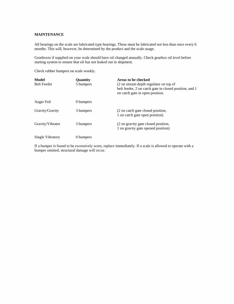
MAINTENANCE
All bearings on the scale are lubricated type bearings. These must be lubricated not less than once every 6 months. This will, however, be determined by the product and the scale usage.
Gearboxes if supplied on your scale should have oil changed annually. Check gearbox oil level before starting system to ensure that oil has not leaked out in shipment.
Check rubber bumpers on scale weekly.
Model Belt Feeder
Quantity 5 bumpers
Areas to be checked (2 on stream depth regulator on top of belt feeder, 2 on catch gate in closed position, and 1 on catch gate in open position.
Auger Fed
0 bumpers
Gravity/Gravity
3 bumpers (2 on catch gate closed position, 1 on catch gate open position)
Gravity/Vibrator
3 bumpers (2 on gravity gate closed position, 1 on gravity gate opened position)
Single Vibratory
0 bumpers
If a bumper is found to be excessively worn, replace immediately. If a scale is allowed to operate with a bumper omitted, structural damage will occur.
GRAVITY GATE 2 POSITION
The gravity gate feeder is used for free flowing products and is air operated. The gravity system works on a single radial gate controlled by two air cylinders mounted back to back. With the unit in fast feed or full open position, both cylinders are retracted. The opening of fast feed can be reduced with a mechanical stop located on the top backside of the gate housing. When the scale changes to slow feed, one cylinder will extend and the gate will become partially closed. The slow feed rate can be changed with a mechanical linkage on the air cylinders. When weigh complete is achieved, the second cylinder will extend and the gate will close completely.
Note: Normal setting for slow or dribble feed is 2.0 lbs. of material per second
Adjustment for slow fill should be made first. The unit should be set to run the entire cycle in slow fill. The unit should fill at approximately 2.0 lbs. per second (this is a guide and not a set value), size and density will effect filling rates. Using the handle attached to the back of the dual cylinders, screw in to decrease and out to increase the filling rate. After several bags have been run all slow fill and weights are correct, then the fast filling adjustment can be made. The fast fill adjustment is adjusted with the handle on top of the gate. Screw the handle in to decrease and out to increase. The flow should be set at a slow rate and slowly increased until there is a uniform filling. Each time the fill rate is increased, an adjustment may need to be made to the PS-1 value or time.
Maintenance
1. Lube 4 bearings, 2 external and 2 internal periodically.
2. Mechanical limiting adjustments - grease lightly to prevent rusting in place.
3. Periodically check rubber gate stop bumpers. Adjust as needed and replace when rubber feels brittle.
4. Periodically check rubber gate seals both front and back.

HOPPER SECTION The weigh hopper is a double door air operated hopper. This unit normally has a limit switch to give a signal that the doors are closed and the weighing can start. Also included in this section are steady rods to prevent the hopper from swinging side to side but will allow it to move up and down freely. The discharge time duration is controlled by an internal timer (refer to programmable controller instruction manual) and should be set to allow the product to clear the hopper. Any excess time is wasted and reduces the cycle rate of the scale. Maintenance
1. Lubricate 4 bearings periodically. 2. Check steady rod for tightness periodically.
REPLACEMENT OF AIR CYLINDER ON WEIGH HOPPER (W.H.) DOORS 1. Remove air supply 2. Remove scale transition and bagging spout. 3. Disconnect the hopper air cylinder by first removing the cotter pins located in the mounting bolts ½”
nuts. Take note of the amount of spacer washers between the air cylinder and door actuator brackets. 4. Remove the airlines from the air fittings by holding in the expansion ring while pulling on the airline. 5. Remove the male rod end and base bracket and female rod end from the old air cylinder. 6. Swap out air fittings and rod ends from old air cylinder to the new replacement weigh hopper air
cylinder. 7. Drill a 1/8” hole through the female rod end and install cotter pin. 8. (Note) that both the male and female rod ends are on as tight as possible before drilling hole. 9. Re-install air cylinder facing in same direction utilizing the hardware removed earlier. When weigh hopper doors are in the closed position, the hopper door cylinder should not bottom out. There should be around ¼” clearance before the actual cylinder can bottom out. A way to check this is to manually operate the air cylinder numerous times until a small dirt ring forms on the shaft of the air cylinder r and then make sure that the ring is showing about ¼” when the doors are in the closed position. If ¼” is not present, you must remove the female rod-end from the cylinder and cut ¼” from the rod end then re-install on cylinder shaft and pin.

DUPLEX/TRIPLEX
INSTALLATION
A duplex or triplex scale is nothing more than multiple simplex scales tied together in a common framework with typically a single discharge point either a manual bag clamp or a connection to an automatic device. The scales are designed totally separate from one another; therefore, the standard manual of a simplex scale will apply to all component parts of a duplex or triplex scale. This feature of scales being totally separate from one another allows you to turn off a scale in the event it is not calibrated correctly or is having any other mechanical problems. The duplex scale can run on one scale and a triplex scale can run on any combination of scale A, B or C. The sequence of operation is somewhat different in that the units are not designed to go A B, A B or A B C, A B C. The program searches for scale A first. If scale A is at weigh complete, it will seek scale A. If scale A is not at weigh complete, it will then search scale B. If both scales are capable of 10 weighments per minute, therefore a duplex scale is capable of 20 weighments per minute and a triplex scale is capable of 30 weighments per minute. If the feed to the hopper above the scale is uniform and either a duplex or triplex scale is operated at 10 bags per minute, theoretically only scale A will operate on the duplex and scale B and C on the triplex will not have a need to operate and will not do so. When initial testing is performed, if product is not available for higher speed operation, scale A will need to be turned off and then the system will automatically search scale B on a duplex and on a triplex. On a triplex scale, if product is still not available, then scale A and B will need to be in the off position in order to test scale C. THEORY Many times the output of a system does not meet expectations. In order to determine where the problem lies; simply watch the scale digital readout. If scale A discharges, then scale B discharges, then A B, etc., etc. Then the scale is generally operating at optimum conditions. If when watching the scale, scale A discharges 5 times more often than scale B, then generally the operator is not hanging bags as fast as the scale will accept them. On a duplex or triplex scale, all feeders are identical; therefore, the amount of time it takes scale A to reach weigh complete and the amount of time it takes scale B and scale C to reach weigh complete should be fairly uniform. There are adjustments in the feeders and if all are adjusted uniformly, this will hold true. If scale A reaches weigh complete in substantially less time than scale B and the feeders have been adjusted identically, then the flow to the surge hopper above the scale needs to be addressed. Many times the flow will go into side A and only go into side B when A is in an overflow condition or visa/versa. It is extremely important when utilizing duplex or triplex scales that the feed to the overhead surge hopper feeds all scales uniformly.

JEM INTERNATIONAL, INC.
Phone: 913-441-4788 Fax: 913-441-1711
MAIN SCALE AND HOUSING PARTS LIST
PART # DESCRIPTION R Simplex Duplex
0001711179 1/8 NPT Bronze Muffler
0448836601 Equalizing rod
0448836602 Equalizing rod SS
0544870002 Seal Hopper R 1 2
3700560112 Cord Male 16/3 8'
3770330042 Brk modular Adpt
3770330043 Spacer T 1/4 NPT
3770330165-J Filter Regulator Series 22 Assembly
3770350010 Shoulder Bolt
5448530000 Hopper 3.5 Cubic Foot MS
5448530002 Hopper 3.5 Cubic Foot SS
5448540000 Hopper 2.0 Cubic Foot MS
5448540002 Hopper 2.0 Cubic Foot SS
5448550000 Hopper 4.0 Cubic Foot MS
5448550003 Hopper 4.0 Cubic Foot SS
5448570000 Frame Hopper MS
5448570001 Frame Hopper SS
5448580001 Door Hopper Right MS
5448580002 Door Hopper Right SS
5448580003 Bracket Hopper Door RH MS
5448580004 Bracket Hopper Door LH MS
5448580013 Bracket Hopper Door RH SS
5448580014 Bracket Hopper Door LH SS
5448700001 Door Hopper Left MS
5448700002 Door Hopper Left SS
7061230000 Rod End Hopper 1/2 male RH
7061510000 Rod End 3/8 RH
7061580000 Rod End 1/2" F LH
7061590000 Rod End 1/2" RH
7623130000 Bearing 5/8"/ Hopper
7623130004 BUSHING SS 5/8/ for ss
7623130005 Bearing Housing UHMW /for ss
7800230000 Housing Assembly MS simplex
7800230002 Housing Assembly MS duplex
7800230005 Housing Assembly SS duplex

7800233003 Housing Assembly MS triplex
7800390000 Transition x 14 Center-Simplex
7800390001 Transition 16" Tall SS
7800390010 Transition Duplex MS (discharge of
7800550101 Load Cell 100KG Single Point R 1 1
7800550604 Summing Box EL604
8953FSC-005 4 Station valve assembly
8953FSC-002 3 Station valve assembly
8953FSC-003 2 Station valve assembly
8953FSC-004 Valve Speed Control
9300030002 Nameplate GJ*
9400010002 Encl 12 x 10 x 6 Fiberglass
9500380000 Terminals
9500410000 Terminal Ground
9500440000 Terminal Fuse Holder (Simplex)
9972275700 Power Supply 24V DC 92 W 1HP
1425195A 3/8 NPT Bronze Muffler
1425197A 1/4 NPT Bronze Muffler
31-261111-C1 Handle, Black Plastic Flush MN
7800230000 SS Housing Assembly SS simplex
7800230003 SS Housing Assembly SS triplex
7800230020-II Channel Mounting MS
78E3-57-15 Latch Vice Action Single Hole R 1 1
79PCM2005 Small end door
79PCM2005S Small end door SS
79PCM2006 Large end door
79PCM2006S Large end door SS
79PCM2007 W H support BKT 4.0
79PCM2007S W H support BKT 4.0 SS
79PCM2008 W H support bracket 3.5
79PCM2008S W H support bracket 3.5 SS
79PCM2009 W H support bracket 2.0
79PCM2009S W H support bracket 2.0 SS
79PCM2010S GG Top Plate Simplex SS
79PCM2011S BF Top Plate Duplex SS
79PCM2012 GG Top Plate Duplex
79PCM2012S GG Top Plate Duplex SS
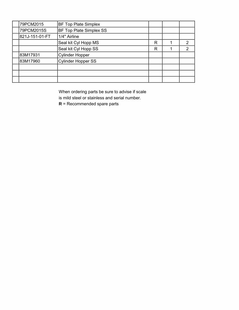
79PCM2015 BF Top Plate Simplex
79PCM2015S BF Top Plate Simplex SS
821J-151-01-FT 1/4" Airline
Seal kit Cyl Hopp MS R 1 2
Seal kit Cyl Hopp SS R 1 2
83M17931 Cylinder Hopper
83M17960 Cylinder Hopper SS
When ordering parts be sure to advise if scale
is mild steel or stainless and serial number.
R = Recommended spare parts

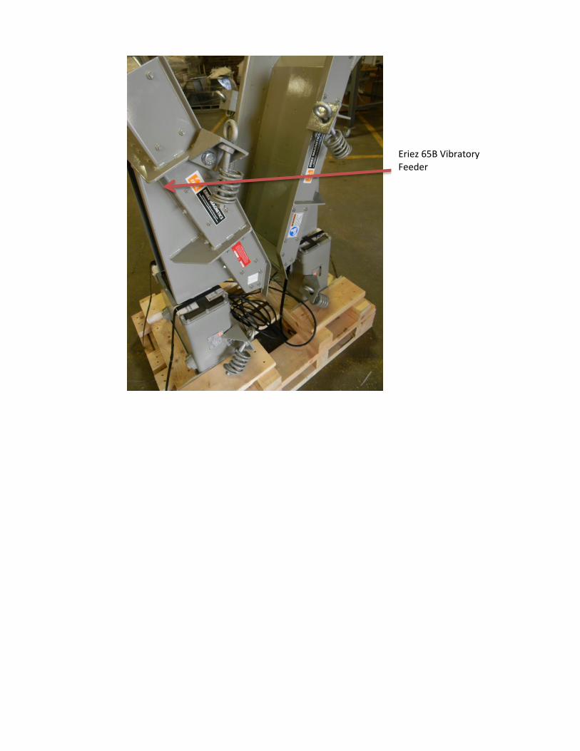
Eriez 65B Vibratory Feeder
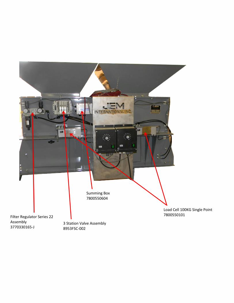
3 Station Valve Assembly 8953FSC-002
Filter Regulator Series 22 Assembly 3770330165-J
Load Cell 100KG Single Point 7800550101
Summing Box 7800550604
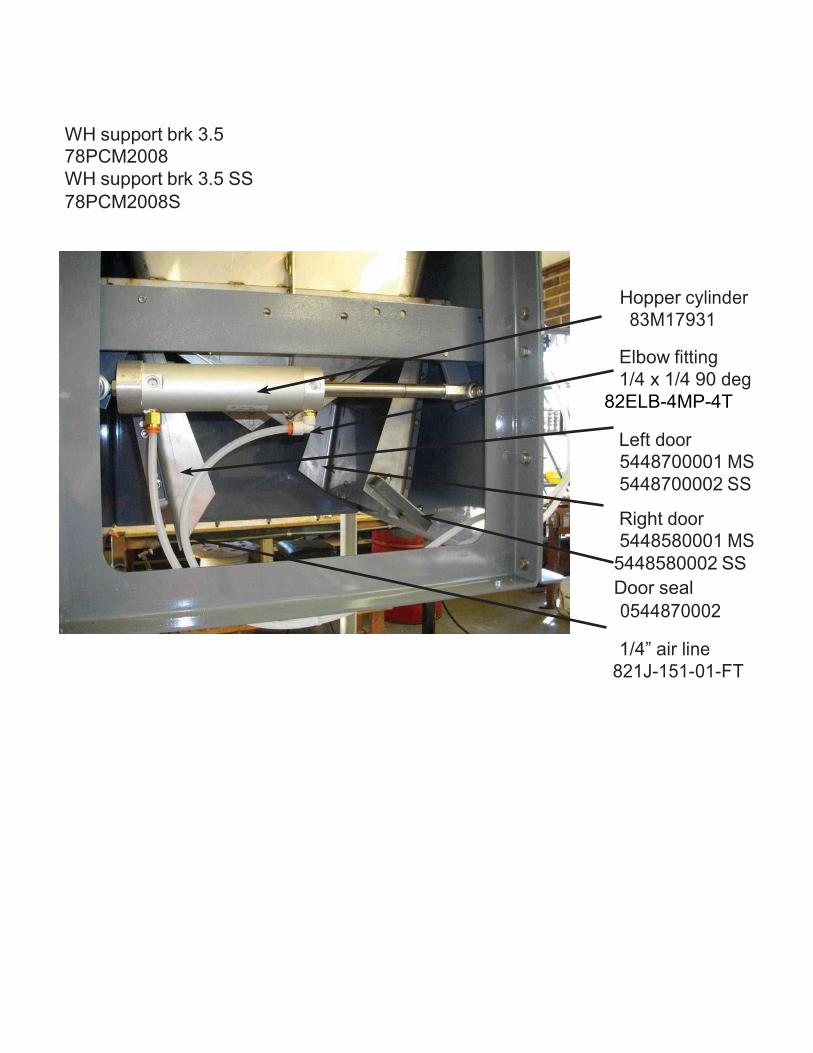
WH support brk 3.5
78PCM2008
WH support brk 3.5 SS
78PCM2008S
Hopper cylinder
83M17931
Elbow fitting
1/4 x 1/4 90 deg
82ELB-4MP-4T
Left door
5448700001 MS
5448700002 SS
Right door
5448580001 MS
5448580002 SS
Door seal
0544870002
1/4” air line
821J-151-01-FT

DUST TIGHT SPOUT
MS and SS
Bearings SS
7623140004 SS
7623140002 MS
Cylinder
83P1SL-05A1C SS
83P1EQL MS
L Bracket
5448200006 SS
5448200004 MS
Spring (not shown)
5448200005
Fittings
82ELB-6MP-4T
Hex nut
(not shown)
5448200036 SS
5448200035 MS
Switch
2795900005 SS
2795900000 MS
Switch wand
2795900010 SS
3770320000 MS Foot Valve (not shown) 8953050002
Clevis
8333260002
Bag Grip
3799990000
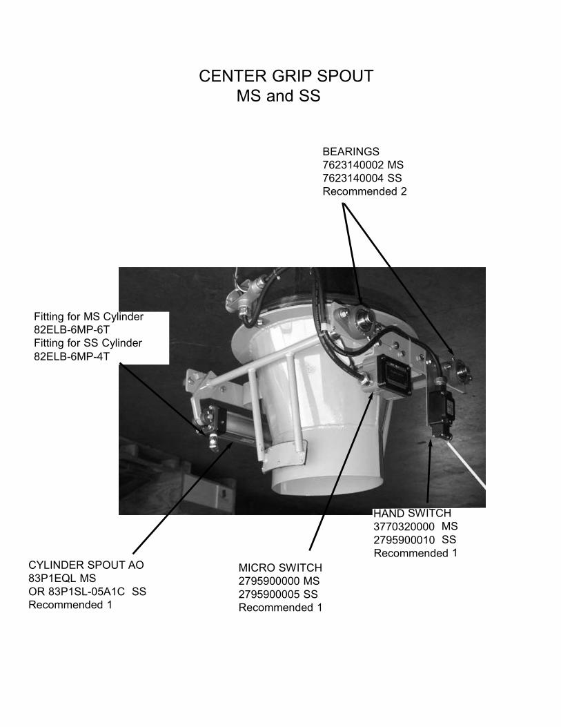
CENTER GRIP SPOUT
MS and SS
BEARINGS
7623140002 MS
7623140004 SS
Recommended 2
Fitting for MS Cylinder
82ELB-6MP-6T
Fitting for SS Cylinder
82ELB-6MP-4T
CYLINDER SPOUT AO
83P1EQL MS
OR 83P1SL-05A1C SS
Recommended 1
MICRO SWITCH
2795900000 MS
2795900005 SS
Recommended 1
HAND SWITCH
3770320000 MS
2795900010 SS
Recommended 1
JEM‐BAT‐220 DIGITAL CONTROLLER
MANUAL
JEM International │ 6867 Martindale │Shawnee. KS 66218
Phone: 913-441-4788 │Fax: 913-441-1711 │www.jembaggingscales.com
JEM BAT-220
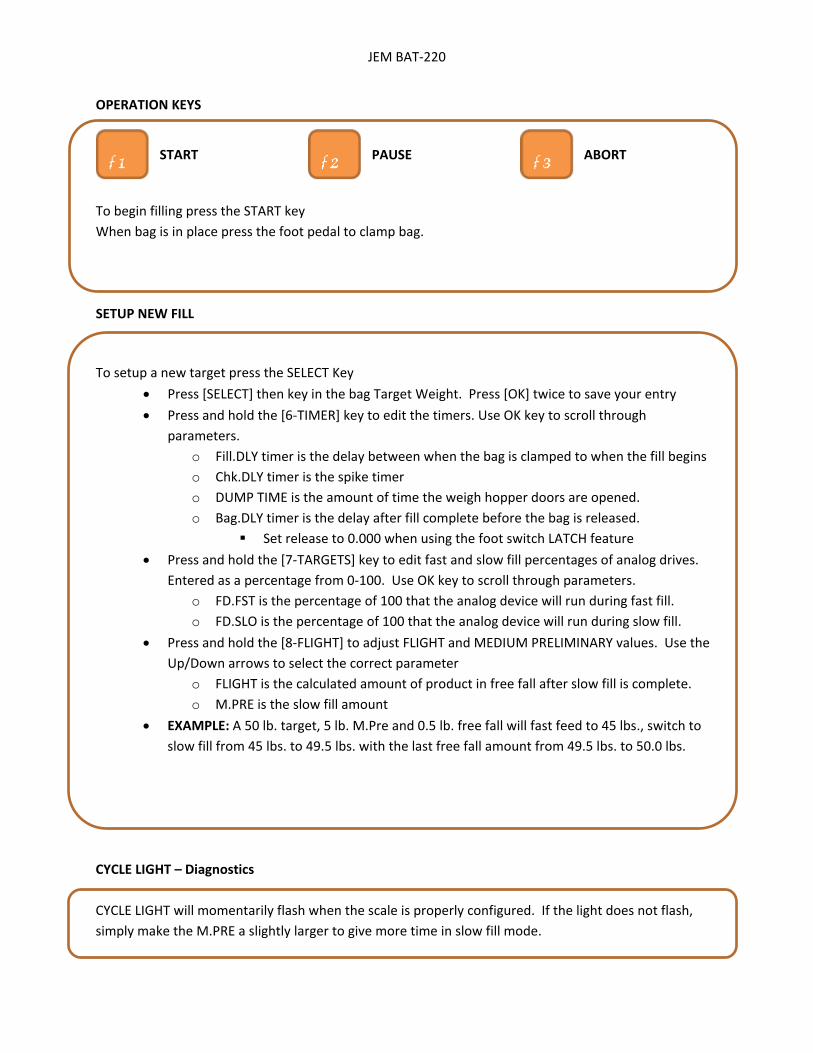
OPERATION KEYS
To begin filling press the START key When bag is in place press the foot pedal to clamp bag. SETUP NEW FILL To setup a new target press the SELECT Key
• Press [SELECT] then key in the bag Target Weight. Press [OK] twice to save your entry • Press and hold the [6-TIMER] key to edit the timers. Use OK key to scroll through
parameters. o Fill.DLY timer is the delay between when the bag is clamped to when the fill begins o Chk.DLY timer is the spike timer o DUMP TIME is the amount of time the weigh hopper doors are opened. o Bag.DLY timer is the delay after fill complete before the bag is released.
Set release to 0.000 when using the foot switch LATCH feature • Press and hold the [7-TARGETS] key to edit fast and slow fill percentages of analog drives.
Entered as a percentage from 0-100. Use OK key to scroll through parameters. o FD.FST is the percentage of 100 that the analog device will run during fast fill. o FD.SLO is the percentage of 100 that the analog device will run during slow fill.
• Press and hold the [8-FLIGHT] to adjust FLIGHT and MEDIUM PRELIMINARY values. Use the Up/Down arrows to select the correct parameter
o FLIGHT is the calculated amount of product in free fall after slow fill is complete. o M.PRE is the slow fill amount
• EXAMPLE: A 50 lb. target, 5 lb. M.Pre and 0.5 lb. free fall will fast feed to 45 lbs., switch to slow fill from 45 lbs. to 49.5 lbs. with the last free fall amount from 49.5 lbs. to 50.0 lbs.
CYCLE LIGHT – Diagnostics CYCLE LIGHT will momentarily flash when the scale is properly configured. If the light does not flash, simply make the M.PRE a slightly larger to give more time in slow fill mode.
START PAUSE ABORT

JEM International 6873 Martindale Road • Shawnee, KS 66218 USA www.JEMBaggingScales.com Phone: 913‐441‐4788 • Fax: 913‐441‐1711
R400 SERIES
ZERO/SPAN CALIBRATION PROCEDURE
With the indicator powered on and in normal weighing mode, perform the following functions to calibrate the R400 series indicators.
(Please note that some variation may exist between firmware versions.)
1. Press and hold the <POWER> + <F3> keys together for a few seconds until "Full Setup" is displayed and then let go.
a. The display should now read "GEN.OPT"
2. Press the <ZERO> key a few times until "SCALE" is displayed.
3. Press the <TARE> key a few times until "CAL" is displayed.
4. Press the <SELECT> key one time to display "ZERO" "CAL ?".
5. Press the <OK> key one time. The current live weight will be displayed, along with "CONT. ?"
6. Remove all weight from the scale spout, and press the <OK> key to proceed a. "Z in P" (Zero in Process) will be displayed briefly followed by the
newly captured zero reference point and "DONE"
7. Press the <OK> key one time to return to "ZERO" "CAL ?".
8. Press the <SELECT> key one time to display "SPAN" "CAL ?".
9. Press the <OK> key one time. The current live weight will be displayed, along with "CONT. ?"
10. Add your desired span calibration weight to the scale spout.
11. Press the <OK> key one time. "WEIGHT" will be displayed, along with a field to enter the span weight value.
12. Enter the desired span weight value with the keypad, and then press the <OK> key.
a. "S in P" (Span in Process) will be displayed briefly followed by the newly captured span reference point and "DONE"
13. Press the <OK> key one time to accept the value and return to "SPAN" "CAL ?".
14. Press the <POWER> key one time to save the changes and exit full setup.

Recipe Data Base Usage
ADDING A NEW RECIPE
The recipe data base function saves the following information in the database for switching between products.
Target weight Slow fill amount Flight Feeder fast percentage Feeder slow percentage Fill delay timer Check delay timer (spike time) Bag Delay timer
The best method would be add the name of the recipe first then enter the parameters. To enter a new recipe name complete the following:
1. Press and hold the UP Arrow key. 2. NAME will appear on the top of the indicator. The current recipe will be on the bottom. 3. USE the alpha‐numeric keypad to enter the name of the product you wish to use. You may enter as long of a
name as you wish. (Just write over the current recipe name that appears) 4. Press the OK key. 5. The indicator will show you the current recipe you just created as well as its recipe code.
This is now the active recipe in the indicator. You can now change whatever parameter you so desire and they will be saved to that recipe when you switch to another.
SWITCHING BETWEEN RECIPES
To switch between recipes complete the following.
1. Press the SELECT key. 2. Code will appear on the screen.
a. Each recipe when entered is assigned a user defined name, ie the name you type in, and a code. 3. You may press OK and enter the code number if you know it or press the arrow key until NAME displays
on the screen. 4. When name appears on the screen press OK. 5. Use the arrow keys to cycle threw the names of the recipes until you find the one you would like to select
and press OK. 6. This is now the active recipe.
DELETING A RECIPE
1. Press and hold the down arrow key with the recipe you wish to delete as the current recipe. 2. The screen will display REMOVE CODE XX. With XX being the code number of the current recipe. 3. Press the OK key. 4. The recipe is now deleted.

Updating the Rinstrum LUA Module Remotely
To remotely update the LUA module in the Rinstrum you will need the following hardware items:
1. A windows based laptop 2. A WIFI internet connection at the scale. This can be the companies WIFI connection or
a hot spot WIFI connection. Most smart phones can be used as a hot spot. 3. An Ethernet patch cable to connect from the computer to the LUA module.
a. A hard wired Ethernet connection can also be made from the LUA module to the local network. If this is done we will change the DCHP setting in the indicator and will need the computer to be on the same network as the one the scale is hard wired to.
To remotely update the LUA module in the Rinstrum you will need the following software items installed on the windows based laptop.
1. Team Viewer – http://www.jembaggingscales.com/contact‐us.php
The following software can be downloaded and installed from the following link:
https://www.dropbox.com/sh/7ifiaojvb284vjm/AAD_UJJRKXz_MwCdxHVXrKyJa?dl=0
2. LUA development environment (recommended) 3. USB‐Serial Driver (recommended) 4. View 400 (recommended)
Software items 2‐4 are recommended but not required. However, if they are not installed prior us, JEM International, accessing your computer to update the LUA module we will have to install them once we are on your computer.
JEM International
Service or Technical Support: 913‐441‐4788
Email: [email protected]
Rinstrum Inc. 1343 Piedmont Drive, Troy, Michigan 48083-1918 USA Telephone: 248 680 0320 Facsimile: 248 499 1331
Toll Free 1 877 829 9152 Web: www.rinstrum.com
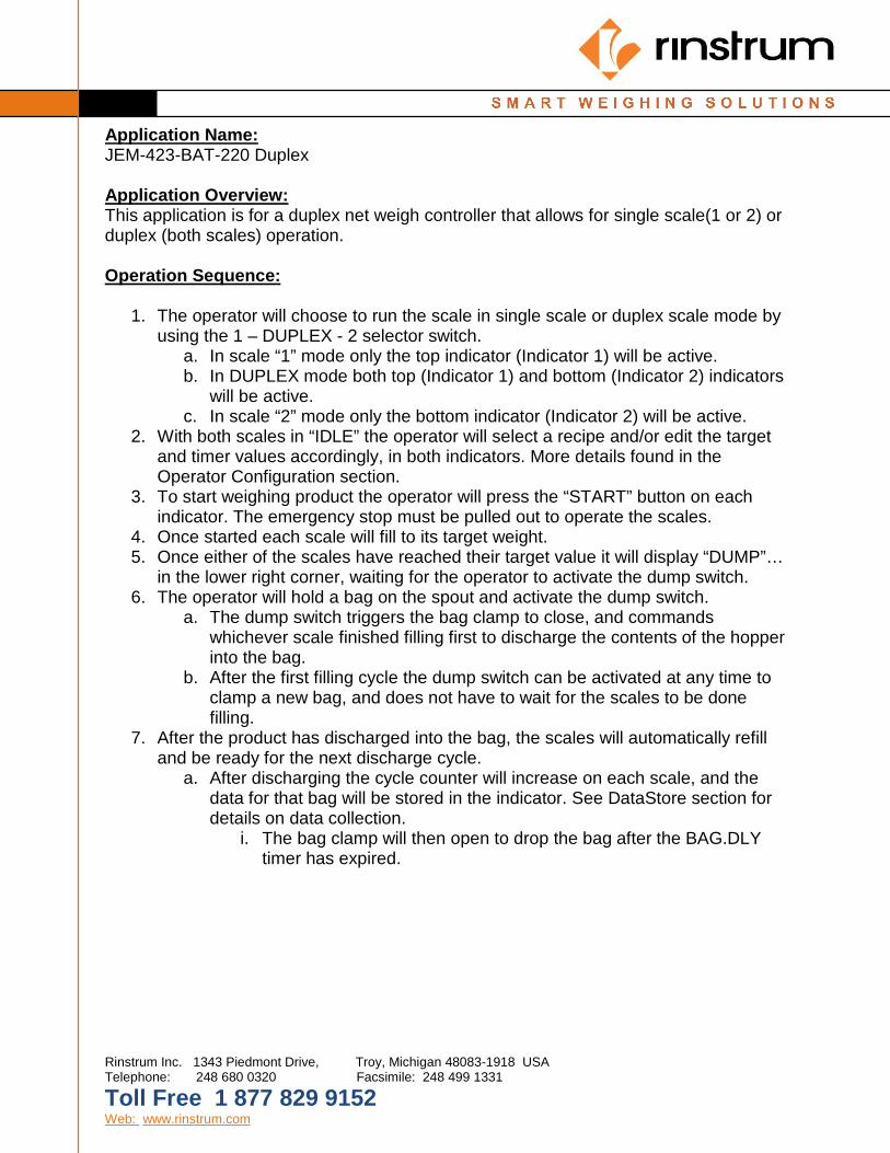
Application Name: JEM-423-BAT-220 Duplex Application Overview: This application is for a duplex net weigh controller that allows for single scale(1 or 2) or duplex (both scales) operation. Operation Sequence:
1. The operator will choose to run the scale in single scale or duplex scale mode by using the 1 – DUPLEX - 2 selector switch.
a. In scale “1” mode only the top indicator (Indicator 1) will be active. b. In DUPLEX mode both top (Indicator 1) and bottom (Indicator 2) indicators
will be active. c. In scale “2” mode only the bottom indicator (Indicator 2) will be active.
2. With both scales in “IDLE” the operator will select a recipe and/or edit the target and timer values accordingly, in both indicators. More details found in the Operator Configuration section.
3. To start weighing product the operator will press the “START” button on each indicator. The emergency stop must be pulled out to operate the scales.
4. Once started each scale will fill to its target weight. 5. Once either of the scales have reached their target value it will display “DUMP”…
in the lower right corner, waiting for the operator to activate the dump switch. 6. The operator will hold a bag on the spout and activate the dump switch.
a. The dump switch triggers the bag clamp to close, and commands whichever scale finished filling first to discharge the contents of the hopper into the bag.
b. After the first filling cycle the dump switch can be activated at any time to clamp a new bag, and does not have to wait for the scales to be done filling.
7. After the product has discharged into the bag, the scales will automatically refill and be ready for the next discharge cycle.
a. After discharging the cycle counter will increase on each scale, and the data for that bag will be stored in the indicator. See DataStore section for details on data collection.
i. The bag clamp will then open to drop the bag after the BAG.DLY timer has expired.

Operator Configuration: (The functionality below highlights what is required to operate this system as it is designed to operate. For additional info on additional key operation please see the indicator operator and reference manuals)
Data Entry:
(Data is entered with the alpha-numerical keypad on the right side of the unit. Remember, after making changes to data you must press the OK key to accept it and again to return to weighing mode.) Up / Down Arrow keys:
• Short Press: These keys are used to scroll through options in the operator menus.
• Long Press: Perform secondary function to ADD and new recipe or DELETE the currently active recipe.
Cancel (C) and OK keys: These keys are used respectively to clear data from and entry field and to accept changes to the data.
Numpad keys: • Short Press: to enter alphanumeric data in the current field. • Long Press: Allows access to the menus outlined in Operator
Configuration. SELECT key:
• Short Press: Allows the operator to view and change the currently active recipe.
• Long Press: Allows access to Operator Configuration menu containing all TARGETS, FLIGHT, and TIMERS.
CLOCK key:
Press and hold the CLOCK (1) key to view and edit the current time and date settings for the indicator.
HOLD key: Press and hold the HOLD (2) key to toggle HOLD MODE operation on or off.
• DISABLED: This is the normal operation mode, and allows the dump gate to automatically operate after the operator presses the foot switch.
• ENABLED: When hold mode is enable the operator may press the foot switch to clamp a bag, but the dump gate will not automatically activate to dispense product into the bag.
COUNT key:
Press and hold the COUNT (3) key to view, edit, and clear the available bag and cycle counters. • BAG.CNT: is the number of bags that have been run for the currently
selected recipe.
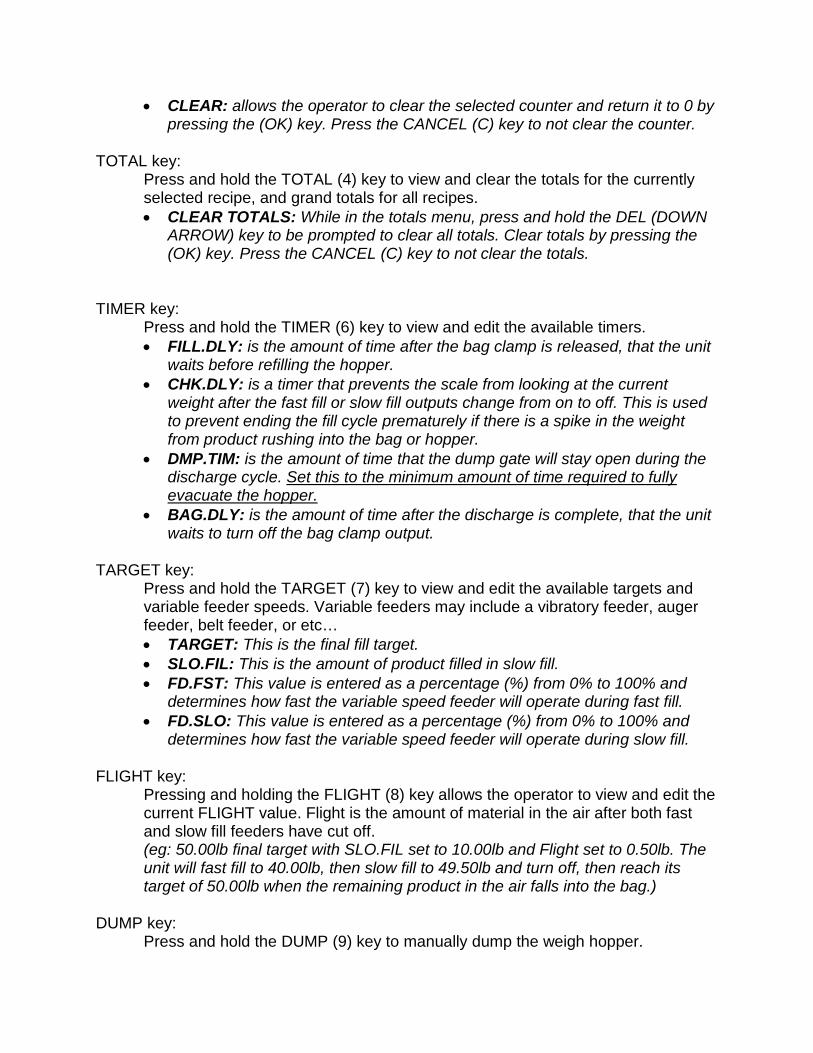
• CLEAR: allows the operator to clear the selected counter and return it to 0 by pressing the (OK) key. Press the CANCEL (C) key to not clear the counter.
TOTAL key:
Press and hold the TOTAL (4) key to view and clear the totals for the currently selected recipe, and grand totals for all recipes. • CLEAR TOTALS: While in the totals menu, press and hold the DEL (DOWN
ARROW) key to be prompted to clear all totals. Clear totals by pressing the (OK) key. Press the CANCEL (C) key to not clear the totals.
TIMER key:
Press and hold the TIMER (6) key to view and edit the available timers. • FILL.DLY: is the amount of time after the bag clamp is released, that the unit
waits before refilling the hopper. • CHK.DLY: is a timer that prevents the scale from looking at the current
weight after the fast fill or slow fill outputs change from on to off. This is used to prevent ending the fill cycle prematurely if there is a spike in the weight from product rushing into the bag or hopper.
• DMP.TIM: is the amount of time that the dump gate will stay open during the discharge cycle. Set this to the minimum amount of time required to fully evacuate the hopper.
• BAG.DLY: is the amount of time after the discharge is complete, that the unit waits to turn off the bag clamp output.
TARGET key:
Press and hold the TARGET (7) key to view and edit the available targets and variable feeder speeds. Variable feeders may include a vibratory feeder, auger feeder, belt feeder, or etc… • TARGET: This is the final fill target. • SLO.FIL: This is the amount of product filled in slow fill. • FD.FST: This value is entered as a percentage (%) from 0% to 100% and
determines how fast the variable speed feeder will operate during fast fill. • FD.SLO: This value is entered as a percentage (%) from 0% to 100% and
determines how fast the variable speed feeder will operate during slow fill. FLIGHT key:
Pressing and holding the FLIGHT (8) key allows the operator to view and edit the current FLIGHT value. Flight is the amount of material in the air after both fast and slow fill feeders have cut off. (eg: 50.00lb final target with SLO.FIL set to 10.00lb and Flight set to 0.50lb. The unit will fast fill to 40.00lb, then slow fill to 49.50lb and turn off, then reach its target of 50.00lb when the remaining product in the air falls into the bag.)
DUMP key: Press and hold the DUMP (9) key to manually dump the weigh hopper.

• The manual dump sequence will close the bag clamp, discharge the hopper, and then open the bag clamp automatically.
INFO key:
Press and hold the INFO (+/-) key to view the application name and version information.
ACC key: Press and hold the ACC (0) key to view the accessories menu.
• This menu holds diagnostic information for the indicator and all installed accessory modules.
H.WARE key: Press and hold the H.WARE ( . ) key to view the hardware menu.
• MVV: select this option to view the millivolt per volt (mV/V) value sensed by the indicator.
Function keys:
F1 – Start Batch F2 – Pause Batch F3 – Abort Batch
Cycle Light:
The cycle light illuminates to identify the portion of the slow fill that is outside of the DLY.CHK(Spike Time). This is used as a troubleshooting tool to insure that the unit is in slow fill long enough for accurate bag weights.
On – Off Switch: The On – Off switch is used to turn the scale controller on or off. DUPLEX – 2 Switch:
a. Choosing “1” will deactivate the lower indicator (scale 2) and run the bagger using the upper indicator (scale 1) only.
b. Choosing “DUPLEX” will activate both scales so that they will both operate while running the bagger.
c. Choosing “2” will deactivate the upper indicator (scale 1) and run the bagger using the lower indicator (scale 2) only.
Emergency Stop: (This switch has 2 positions, pulled out is the normal operating position, and pushed in, in case of emergencies. The functionality is defined as follows.)
a. When the Emergency Stop is pulled out the scale will operate normally.

b. When the Emergency Stop is pushed in the, power is removed from the relay rack, solenoid valves, and feeders. This will also retract the bag clamp to its open position.
a. The scale controller will be placed in a pause condition. Once the Emergency Stop has been returned to the pulled out position the operator may resume normal operation by triggering a start with the F1 key.
Supervisor Configuration
Press and hold the POWER and START (F1) keys together to enter the Supervisor Configuration menu. (This menu is protected with a passcode to be supplied upon request to JEM International.) • SCALE menu: This menu has options that will affect the scale operation.
o FILTER: Used to adjust the amount of filtering applied to the load signal. Filtering should be set to the minimum amount required. The default value is 0.20s and is recommended for most applications.
o COR.TYP: Allows the supervisor to alter the fill correction type. Available options are AUT.FLT, MAN.FLT, AUT.JOG, and JOG. These are defined in the Correction Type section. The default is AUT.FLT and is recommended for most applications.
• CALIBRATE menu: Allows the supervisor to scroll through the options to calibrate the scale.
o ZERO: When “CAL ZERO” is displayed, remove all weight from the scale and press the (OK) key to calibrate the scale zero point. “Z in P” (Zero in Process) will be displayed while the unit is
calibrating, followed by “ZERO OK” when complete. o SPAN: When “CAL SPAN” is displayed, add test weigh to the scale
and press the (OK) key. “SPAN” will be shown on the top display and a weight on the
lower display. Used the keypad to enter the value of the applied test weight, and press the (OK) key to calibrate the scale span point.
• “S in P” (Span in Process) will be displayed while the unit is calibrating, followed by “SPAN OK” when complete.
Correction Type:
• AUTO FLIGHT (AUT.FLT) o The unit will attempt to calculate and optimize the Flight value
automatically as it is being used. This allows the unit to maintain accuracy and consistency throughout the filling process.
• MANUAL FLIGHT (MAN.FLT) o The unit will use the operator entered Flight value for every fill cycle, no
automatic correction is performed • AUTO JOG (AUT.JOG)

o The unit will utilize automatic flight correction, add a jog sequence to the end of the fill cycle. Additional settings will be added to the FLIGHT menu to control the jogging sequence.
• MANUAL JOG (JOG) o The unit will utilize manual flight correction, add a jog sequence to the end
of the fill cycle. Additional settings will be added to the FLIGHT menu to control the jogging sequence.
• Jog settings: o These settings are added to the FLIGHT menu if AUT.JOG or JOG
correction type is chosen. JOG.ON: is the amount of time the slow fill output will be activated
during the jog sequence JOG.OFF: is the amount of time to delay between JOG.ON pulses. JOG.NUM: is the maximum number of times the unit will attempt to
jog before the target value is reached. Setting JOG.NUM to 0 will force the unit to continue jogging until the target value is reached. The default value is 0.
Recipe Database:
• Select a recipe from the database: o Enter the recipe menu with a short press of the “SELECT” key. o The currently selected recipe name and code number will display for a few
seconds followed by the recipe select menu. Use the ARROW KEYS to scroll through the options and press “OK” to select it.
o Recipe menu options: CODE: allows the operator to select a recipe from the database by
entering the recipe code. NAME: allows the operator to select a recipe by scrolling through a
list of all recipe names. LOT.NUM: allows the operator to assign a lot number to the
product currently being run. This lot number gets stored with each weighment in DataStore.
QUIT: exit menu and return to normal weighing mode.
• Add a new recipe to the database: o From weighing mode “IDLE”, press and hold the up arrow “ADD” key for
2 seconds. o The operator will be prompted to enter a new recipe name. The field will
be pre-populated with the currently selected recipe name. Use the arrow keys to change the cursor position and or the “C”
clear key to delete any unwanted characters. Enter the new recipe name using the keypad and then press “OK”
to accept it. The operator will be prompted that the new recipe has been
created and the code number that was assigned to it.
o The new recipe is created with the same settings as the previously selected recipe. These settings can be altered and stored at any time by entering new values in any of the TARGETS, FLIGHT, or TIMERS.
• Remove a recipe from the database:
o From weighing mode “IDLE”, press and hold the down arrow “DEL” key for 2 seconds.
o The operator will be prompted to remove the currently selected recipe code. Press the “OK” key to remove the recipe. Press the “C” key to exit without removing the recipe.
DataStore:
To collect the data from the scale indicator the operator may perform the following procedure. 1. Stop the filling / batching sequence by pressing the “ABORT” key. The
indicator will display “IDLE” on the lower portion of the display. 2. Insert a BLANK USB flash drive into the USB port found on the M4223
module that is located on the back of the indicator. a. The Indicator will analyse the flash drive, and then open the USB menu
automatically. 3. The indicator will display “USB” on the upper portion of the display, and a
prompt in the lower right corner to “USE ARROWS OR REMOVE USB” 4. The operator may choose from the following 3 options by using the arrow
keys to scroll through the options and then pressing the “OK” key to accept the option.
a. “TO USB” – is used to download the data files from the indicator. • The data files that are downloaded will contain the
Datastore_xxxxxxx.csv file, where xxxxxxx is the serial number of the indicator. This Datastore_xxxxxxx.csv file can be opened in a pc software like Excel to view the captured data from each filling cycle.
b. “FROM USB” – is used to upload new data files to the indicator if an update to the indicator software is required.
• This option should not be chosen unless asked to do so by JEM International personnel.
c. “EJECT USB” – This option can be chosen to safely remove the USB flash drive from the indicator.
• “USB REMOVE” will be displayed when it is safe to remove the usb drive.
• Once removed the indicator will return to “IDLE” and be ready for use. If a software update was loaded the indicator will automatically reboot to apply the update.


