nVent ERICO System 3000 - taacsa.com
20
nVent ERICO System 3000 Lightning Protection Systems
Transcript of nVent ERICO System 3000 - taacsa.com
nVent ERICO System 3000Lightning Protection Systems

2 | nVent.com/ERICO
A military combat training center upgraded their critical instrumentation system and needed it to be well protected against potential lightning strikes damage. The site consists of 25 free standing cell phone towers which support the center’s live training network. Each tower is part of a high throughput, low latency network that carries video, voice, and data throughout the facility. With personnel safety and the reliability of electrical systems being so critical to the center’s operations, the design engineers knew that they had to pick the right lightning protection system.
With these challenges, the engineers turned to nVent ERICO System 3000 to provide the reliability and performance that they need for this critical installation. System 3000 meets the Telecommunications Industry Association standards, providing the engineers with the con�dence that they were making the right choice.
System 3000 is comprised of the proprietary nVent ERICO Dynasphere which captures lightning, the nVent ERICO Ericore downconductor that will safely transmit a direct strike to the earthing system to while protecting the critical equipment and �ber optics while preventing a spark over, and a robust grounding system including nVent ERICO Cadweld connections.
nVent.com/ERICO | 3
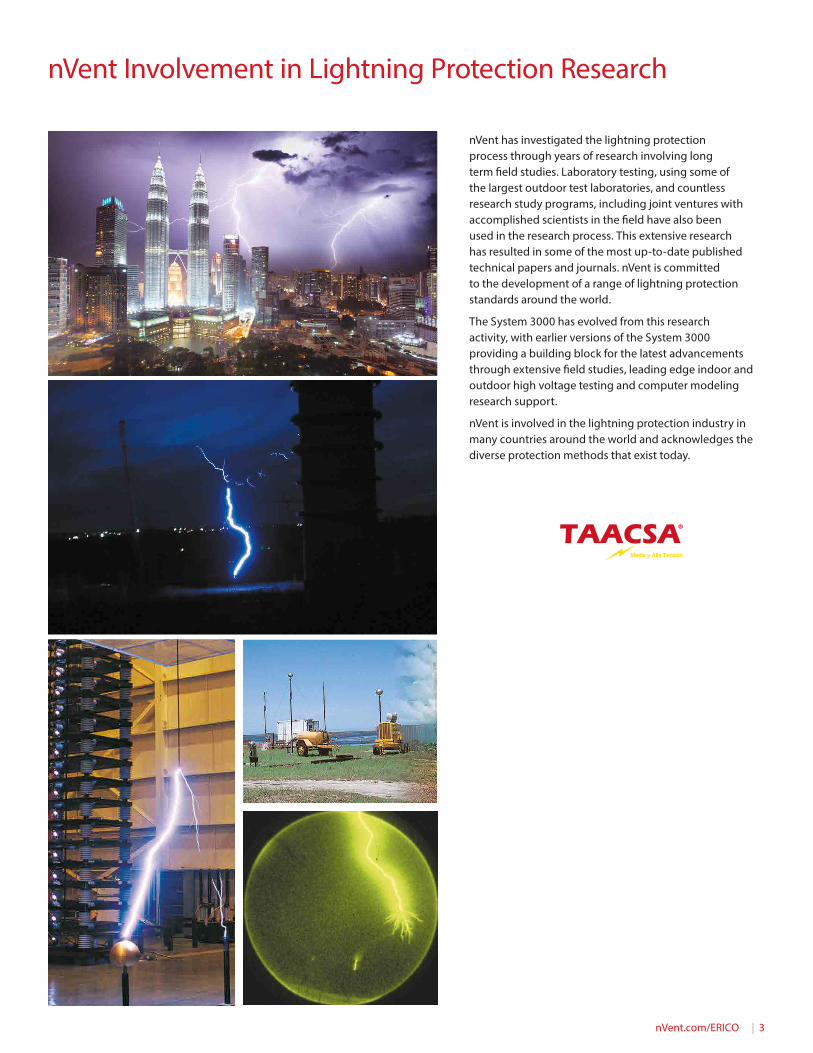
nVent has investigated the lightning protection process through years of research involving long term �eld studies. Laboratory testing, using some of the largest outdoor test laboratories, and countless research study programs, including joint ventures with accomplished scientists in the �eld have also been used in the research process. This extensive research has resulted in some of the most up-to-date published technical papers and journals. nVent is committed to the development of a range of lightning protection standards around the world.
The System 3000 has evolved from this research activity, with earlier versions of the System 3000 providing a building block for the latest advancements through extensive �eld studies, leading edge indoor and outdoor high voltage testing and computer modeling research support.
nVent is involved in the lightning protection industry in many countries around the world and acknowledges the diverse protection methods that exist today.
nVent Involvement in Lightning Protection Research
4 | nVent.com/ERICO
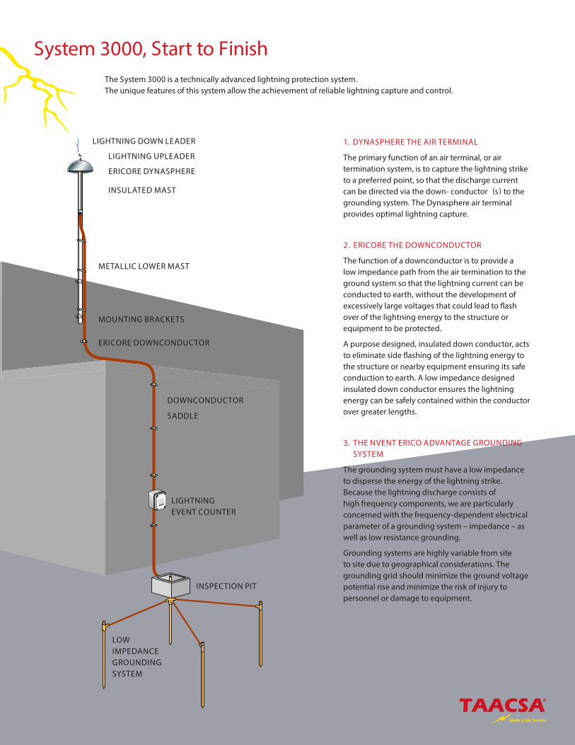
LIGHTNING UPLEADER
ERICORE DYNASPHERE
INSULATED MAST
METALLIC LOWER MAST
MOUNTING BRACKETS
ERICORE DOWNCONDUCTOR
DOWNCONDUCTOR
SADDLE
LIGHTNING EVENT COUNTER
INSPECTION PIT
LOW IMPEDANCE GROUNDING SYSTEM
LIGHTNING DOWN LEADER
The System 3000 is a technically advanced lightning protection system. The unique features of this system allow the achievement of reliable lightning capture and control.
1. DYNASPHERE THE AIR TERMINAL
The primary function of an air terminal, or air termination system, is to capture the lightning strike to a preferred point, so that the discharge current can be directed via the down- conductor (s) to the grounding system. The Dynasphere air terminal provides optimal lightning capture.
2. ERICORE THE DOWNCONDUCTOR
The function of a downconductor is to provide a low impedance path from the air termination to the ground system so that the lightning current can be conducted to earth, without the development of excessively large voltages that could lead to �ash over of the lightning energy to the structure or equipment to be protected.
A purpose designed, insulated down conductor, acts to eliminate side �ashing of the lightning energy to the structure or nearby equipment ensuring its safe conduction to earth. A low impedance designed insulated down conductor ensures the lightning energy can be safely contained within the conductor over greater lengths.
3. THE NVENT ERICO ADVANTAGE GROUNDING SYSTEM
The grounding system must have a low impedance to disperse the energy of the lightning strike. Because the lightning discharge consists of high frequency components, we are particularly concerned with the frequency-dependent electrical parameter of a grounding system – impedance – as well as low resistance grounding.
Grounding systems are highly variable from site to site due to geographical considerations. The grounding grid should minimize the ground voltage potential rise and minimize the risk of injury to personnel or damage to equipment.
System 3000, Start to Finish
nVent.com/ERICO | 5
6 Point Plan
TOTAL FACILITY PROTECTION
The consequences of an unexpected lightning strike or power surge can be catastrophic for a facility:
• Personnel are at risk.• Critical equipment may be damaged or destroyed. • Data can be corrupted. • The costs of operational downtime and lost revenue can be very
substantial.
As industries become more dependent on increasingly sensitive equipment, proper protection from lightning and dangerous over-voltage transients is necessary.
With over 60 years of research, testing and product development, nVent ERICO has acknowledged that no single technology can totally eliminate vulnerability to lightning and surges.
The nVent ERICO Six Point Plan of Protection is designed to provide total facility protection by integrating several concepts.
The Six Point Plan will minimize the risk of damage to facilities through:
• Direct Strike Protection• Grounding and Bonding• Surge and Over-voltage Transient Protection
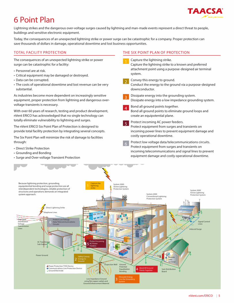
Lightning strikes and the dangerous over-voltage surges caused by lightning and man-made events represent a direct threat to people, buildings and sensitive electronic equipment.
Today, the consequences of an unexpected lightning strike or power surge can be catastrophic for a company. Proper protection can save thousands of dollars in damage, operational downtime and lost business opportunities.
THE SIX POINT PLAN OF PROTECTION
1 Capture the lightning strike. Capture the lightning strike to a known and preferred attachment point using a purpose-designed air terminal system.
2 Convey this energy to ground. Conduct the energy to the ground via a purpose-designed downconductor.
3 Dissipate energy into the grounding system. Dissipate energy into a low impedance grounding system.
4 Bond all ground points together. Bond all ground points to eliminate ground loops and create an equipotential plane.
5 Protect incoming AC power feeders. Protect equipment from surges and transients on incoming power lines to prevent equipment damage and costly operational downtime.
6 Protect low voltage data/telecommunications circuits. Protect equipment from surges and transients on incoming telecommunications and signal lines to prevent equipment damage and costly operational downtime.
1
Power Distribution Panel
Telephone Main Distribution Frame
PCS, Radio & Telemetry Equipment
Power Ground
AC Transformer Sub Station
Overhead Distribution Voltage Transmission Lines
Telephone Lines
Direct Lightning Strike
System 3000 Active Lightning Protection System
Capture the lightning strike
Dissipate Energy into the Grounding System
Low Impedance Ground using �at copper radials and
Ground Enhancement Material
Inspection Well
Safely Convey Energy to Ground
Protect Incoming AC Power Feeders
IS File
Server
PABX
InverterRecti�er
Batteries
Ground Potential Equalization Bonding
TVSSRemote Data Terminal
Sub-Distribution Board
Bond All Ground Points Together
PrinterBilling Computer
Signal Control Lines
Induced Surge
System 3000 Active Lightning Protection SystemSystem 2000
Conventional Lightning Protection System
Protect Low Voltage Data/Telecommunications Circuits
Because lightning protection, grounding, equipotential bonding and surge protection are all interdependent technologies, reliable protection of structures and operations demands an integrated system approach.
Power Protection TVSS DeviceCommunications Line Protection DeviceGround Electrode
6
5
2
3
4
6 | nVent.com/ERICO
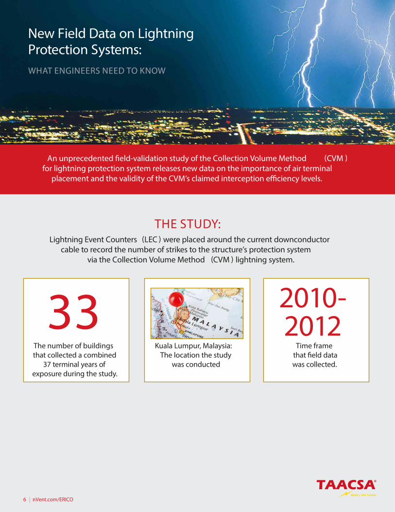
THE STUDY:Lightning Event Counters (LEC ) were placed around the current downconductor
cable to record the number of strikes to the structure’s protection system via the Collection Volume Method (CVM ) lightning system.
An unprecedented �eld-validation study of the Collection Volume Method (CVM ) for lightning protection system releases new data on the importance of air terminal
placement and the validity of the CVM’s claimed interception e�ciency levels.
2010- 2012
The number of buildings that collected a combined
37 terminal years of exposure during the study.
Kuala Lumpur, Malaysia: The location the study
was conducted
Time frame that �eld data was collected.
33
New Field Data on Lightning Protection Systems:WHAT ENGINEERS NEED TO KNOW
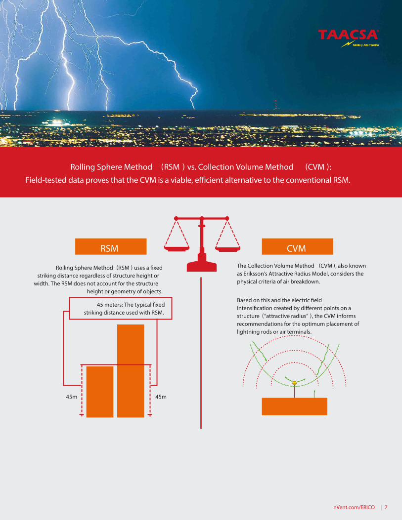
Rolling Sphere Method (RSM ) uses a �xed striking distance regardless of structure height or
width. The RSM does not account for the structure height or geometry of objects.
The Collection Volume Method (CVM ), also known as Eriksson’s Attractive Radius Model, considers the physical criteria of air breakdown.
Based on this and the electric �eld intensi�cation created by di�erent points on a structure (“attractive radius” ), the CVM informs recommendations for the optimum placement of lightning rods or air terminals.
45m 45m
45 meters: The typical �xed striking distance used with RSM.
Rolling Sphere Method (RSM ) vs. Collection Volume Method (CVM ):
Field-tested data proves that the CVM is a viable, e�cient alternative to the conventional RSM.
nVent.com/ERICO | 7
RSM CVM
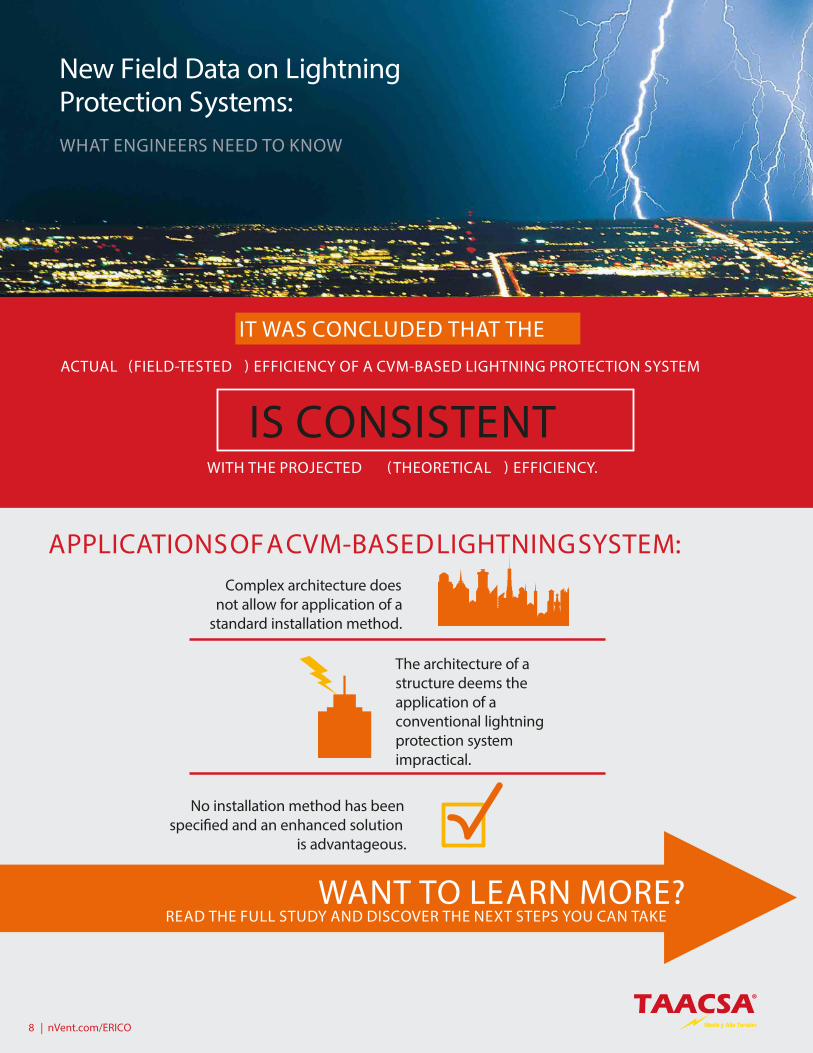
IT WAS CONCLUDED THAT THE
ACTUAL (FIELD-TESTED ) EFFICIENCY OF A CVM-BASED LIGHTNING PROTECTION SYSTEM
WITH THE PROJECTED ( THEORETICAL ) EFFICIENCY.
New Field Data on Lightning Protection Systems:WHAT ENGINEERS NEED TO KNOW
APPLICATIONS OF A CVM-BASED LIGHTNING SYSTEM:
The architecture of a structure deems the application of a conventional lightning protection system impractical.
No installation method has been speci�ed and an enhanced solution
is advantageous.
Complex architecture does not allow for application of a
standard installation method.
WANT TO LEARN MORE? READ THE FULL STUDY AND DISCOVER THE NEXT STEPS YOU CAN TAKE
8 | nVent.com/ERICO
IS CONSISTENT
nVent.com/ERICO | 9
Air terminal placement is essential to an e�cient and e�ective lightning protection system. An unprecedented �eld-validation study of the Collection Volume Method (CVM ) for lightning protection systems sheds powerful new insights on optimum air terminal placement and the validity of the CVM’s claimed interception e�ciency levels.
Outlined below is what engineers need to know before starting their next lightning protection project.
THE FINDINGS
• Enhanced air terminals with CVM placement, such as the Dynasphere, o�er a zone of protection consistent with claimed interception e�ciency levels of 84% – 99%, based on the desired level of protection.
ENHANCED AIR TERMINALS WITH CVM PLACEMENT, SUCH AS THE DYNASPHERE, OFFER A ZONE OF PROTECTION CONSISTENT WITH CLAIMED INTERCEPTION EFFICIENCY LEVELS OF 84% – 99%, BASED ON THE DESIRED LEVEL OF PROTECTION.
– Lightning rods can be placed according to various models currently used in the lightning protection �eld.
– The most common method for air terminal placement is the Rolling Sphere Method (RSM ), which is based on the simple Electro Geometric Model (EGM ) for striking distance.
– The simple EGM does not account for the importance of the structure height or geometry of objects on the structure.
– The RSM uses a �xed striking distance, typically 45 meters, regardless of structure height or width. This means that a 5-meter structure is given the same capture area and strike probability as a 100-meter communications tower.
• The Collection Volume Method (CVM ), also known as Eriksson’s Attractive Radius Model, considers the physical criteria of air breakdown, and the electric �eld intensi�cation created by di�erent points on a structure.
THE COLLECTION VOLUME METHOD (CVM ), ALSO KNOWN AS ERIKSSON’S ATTRACTIVE RADIUS MODEL, CONSIDERS THE PHYSICAL CRITERIA OF AIR BREAKDOWN, AND THE ELECTRIC FIELD INTENSIFICATION CREATED BY DIFFERENT POINTS ON A STRUCTURE.
– CVM takes into consideration the building’s features. It then uses this information to provide the optimum lightning protection system for a structure, i.e., the most e�ective placement of air terminals for a selected interception e�ciency level.
• Based on �eld data, the actual (�eld-tested ) e�ciency of a CVM- based lightning protection system is consistent with the projected (theoretical ) e�ciency.
– Overall, estimates of the strike “yield” demonstrate that the interception e�ciency predicted by the CVM is consistent with the observed capture frequency. This means that the lightning interception e�ciency is at least as high as the claimed levels (84% – 99% ).
THE STUDY
• “Interception e�ciency of CVM-based lightning protection systems for buildings and the fractional Poisson model,” published in December 2015 by Harold S. Haller and Wojbor A. Woyczynski, examines the level of interception e�ciency claimed by the CVM.
• This study is the only of its kind, as it demonstrated that the CVM meets its claimed interception e�ciencies based on �eld data.
• A study of 33 buildings was conducted between 2010 and
Read The Full Study:

10 | nVent.com/ERICO
2012, in Kuala Lumpur, in the Klang Valley region of Malaysia.
• The buildings, protected by a system of air terminals optimally placed according to the CVM, were surveyed by TÜV-Hessen, an independent expert organization.
• For each site, System 3000 products were used. The number of strikes to the to the air terminals were obtained from “lightning event counters” (LEC ) placed around the lightning downconductor cable.
• At each installation, TÜV-Hessen surveyed the buildings and documented evidence of lightning damage and recorded the readings of instruments showing the number of captured lightning events.
• The average interception e�ciency of the lightning protection systems was measured against the predicted average interception e�ciency on which the CVM-optimized terminal placement had been based. The average interception e�ciency was found to di�er by only 0.20% from the predicted e�ciency.
• Analyzed �eld data was also compared to mathematical models of CVM.
– Through a new mathematical model, the study authors were able to replicate the characteristic randomness of a natural event like a lightning strike.
– Their model con�rms that the interception e�ciency of a CVM-based lightning protection system is consistent with claims of 84% - 99% e�ective based on the desired level of protection.
SYSTEM 3000 LIGHTNING PROTECTION PRODUCTS
SYSTEM 3000 PRODUCTS, WHEN USED TOGETHER, CREATE A TECHNICALLY ADVANCED LIGHTNING PROTECTION SYSTEM. THE UNIQUE FEATURES OF THIS SYSTEM ALLOW THE ACHIEVEMENT OF RELIABLE LIGHTNING CAPTURE AND CONTROL, WHEN COMBINED WITH CVM PLACEMENT.• System 3000 products, when used
together, create a technically advanced lightning protection system. The unique features of this system allow the achievement of reliable lightning capture and control, when combined with CVM placement.
• The Dynasphere air terminal provides a preferred point for lightning discharges that would otherwise strike and damage an unprotected structure and/or its contents. The Dynasphere is optimally connected to an Ericore downconductor and low impedance grounding system to provide a totally integrated system.
• System 3000 includes:
– Dynasphere air terminal
– Ericore downconductor
– Lightning Event Counter (LEC )
– Purpose designed low impedance grounding system
LABORATORY TESTING, USING SOME OF THE LARGEST OUTDOOR TEST LABORATORIES, AND COUNTLESS RESEARCH STUDY PROGRAMS—INCLUDING JOINT VENTURES WITH ACCOMPLISHED SCIENTISTS IN THE FIELD—HAVE ALSO BEEN USED IN THE RESEARCH PROCESS.
New Field Data on Lightning Protection Systems:WHAT ENGINEERS NEED TO KNOW
nVent.com/ERICO | 11
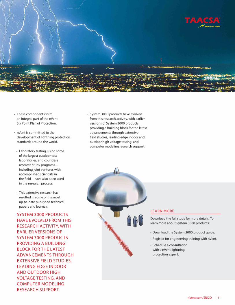
• These components form an integral part of the nVent Six Point Plan of Protection.
• nVent is committed to the development of lightning protection standards around the world.
– Laboratory testing, using some of the largest outdoor test laboratories, and countless research study programs— including joint ventures with accomplished scientists in the �eld—have also been used in the research process.
– This extensive research has resulted in some of the most up-to-date published technical papers and journals.
– System 3000 products have evolved from this research activity, with earlier versions of System 3000 products providing a building block for the latest advancements through extensive �eld studies, leading edge indoor and outdoor high voltage testing, and computer modeling research support.
SYSTEM 3000 PRODUCTS HAVE EVOLVED FROM THIS RESEARCH ACTIVITY, WITH EARLIER VERSIONS OF SYSTEM 3000 PRODUCTS PROVIDING A BUILDING BLOCK FOR THE LATEST ADVANCEMENTS THROUGH EXTENSIVE FIELD STUDIES, LEADING EDGE INDOOR AND OUTDOOR HIGH VOLTAGE TESTING, AND COMPUTER MODELING RESEARCH SUPPORT.
LEARN MORE
Download the full study for more details. To learn more about System 3000 products:
• Download the System 3000 product guide.
• Register for engineering training with nVent.
• Schedule a consultation with a nVent lightning protection expert.
12 | nVent.com/ERICO
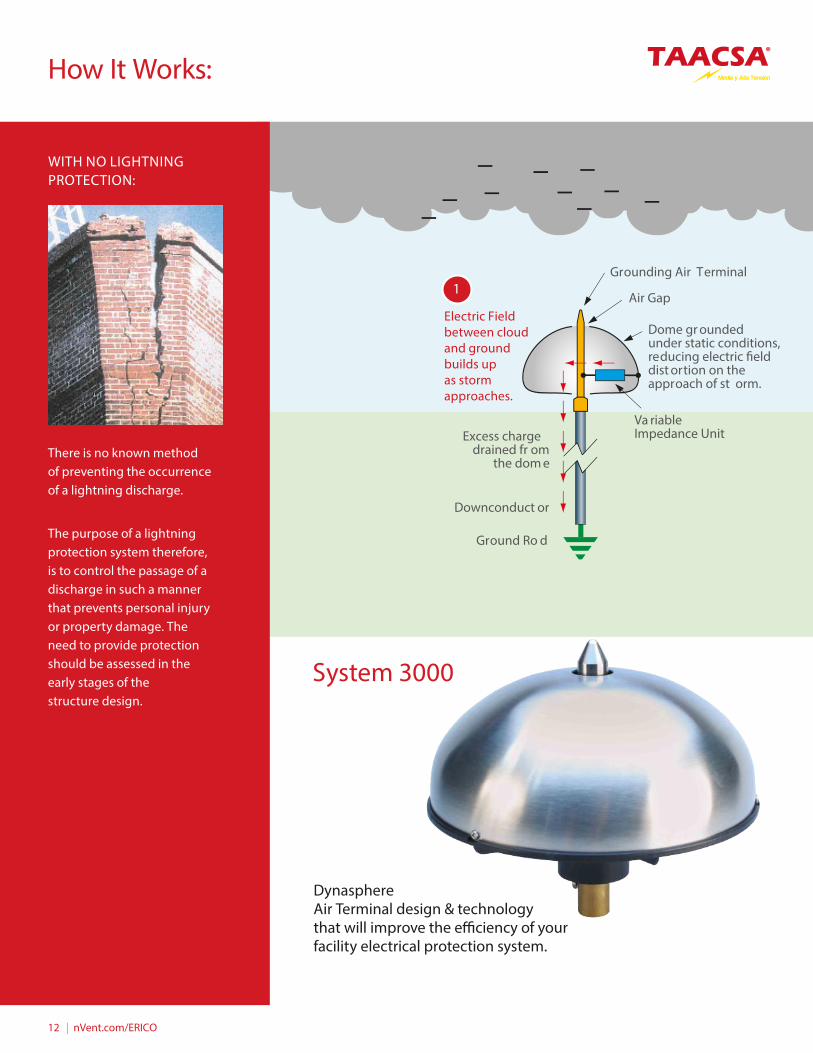
Grounding Air Terminal
Downconduct or
Ground Ro d
Air Gap
Dome gr ounded under static conditions, reducing electric �eld dist ortion on the approach of st orm.
Va riable Impedance UnitExcess charge
drained fr om the dom e
Electric Field between cloud and ground builds up as storm approaches.
There is no known method of preventing the occurrence of a lightning discharge.
The purpose of a lightning protection system therefore, is to control the passage of a discharge in such a manner that prevents personal injury or property damage. The need to provide protection should be assessed in the early stages of the structure design.
WITH NO LIGHTNING PROTECTION:
How It Works:
System 3000
DynasphereAir Terminal design & technology that will improve the e�ciency of your facility electrical protection system.
1
nVent.com/ERICO | 13
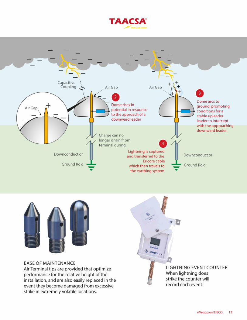
Capacitive Coupling
Downconduct or
Charge can no longer dr ain fr om terminal during.
Downconduct or
Ground Ro d Ground Ro d
Air Gap Air Gap
Air GapDome rises in potential in response to the approach of a downward leader
Dome arcs to ground, promoting conditions for a stable upleader leader to intercept with the approaching downward leader.
Lightning is captured and transferred to the
Ericore cable which then travels to the earthing system
LIGHTNING EVENT COUNTER
When lightning does strike the counter will record each event.
4
32
EASE OF MAINTENANCEAir Terminal tips are provided that optimize performance for the relative height of the installation, and are also easily replaced in the event they become damaged from excessive strike in extremely volatile locations.

14 | nVent.com/ERICO
Why It Works:
The number of strikes to the protection system of the structures in this study were obtained from “lightning event counters” (LEC ) placed around the lightning downconductor cable. Overall, estimates of the strike “yield” demonstrate that the interception rate predicted by the CVM is in excellent agreement with the observed capture frequency. This means that the lightning-interception rate is at least as high as the claimed protection levels, which lie in the 87 – 99% range.
The second study, conducted from 1990 through 2000 in Malaysia, quanti�ed interception e�ciency. The study consisted of a statistically valid sample of buildings mainly in the Klang Valley region of Kuala Lumpur. The 47 sites had between 1 and 5 buildings per site with a mean structure height of 58 m (190 ft ).
The mean actual protection level was 78%, con�rming that up to 22% of low-intensity �ashes under 10 kA could bypass the lightning protection system (LPS ). Mitigating factors such as budget constraints and subsequent changes to the structures (e.g. the addition of antennas and extensions ) impacted the initial design and prevented the protection level from being higher. At the end of the study, the actual interception e�ciency was 86%, ten percent better than predicted.
Both of these long-term �eld studies are now published in independently peer- reviewed scienti�c journal publications.
AIR TERMINAL TIP SELECTION BASED ON RELATIVE AIR TERMINAL HEIGHT
50 M
20 M
<20 M
INTERCEPTORFor small areas or structures <20m
nVent.com/ERICO | 15
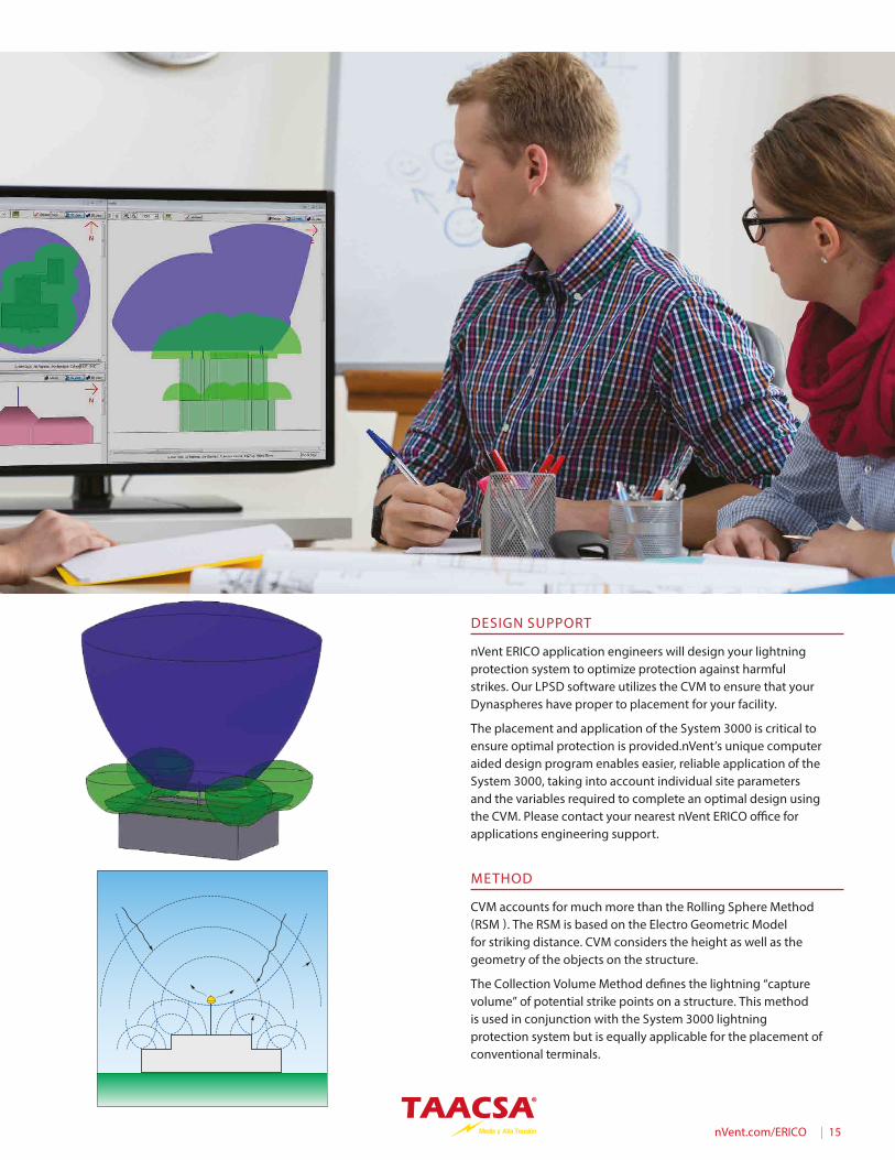
DESIGN SUPPORT
nVent ERICO application engineers will design your lightning protection system to optimize protection against harmful strikes. Our LPSD software utilizes the CVM to ensure that your Dynaspheres have proper to placement for your facility.
The placement and application of the System 3000 is critical to ensure optimal protection is provided.nVent’s unique computer aided design program enables easier, reliable application of the System 3000, taking into account individual site parameters and the variables required to complete an optimal design using the CVM. Please contact your nearest nVent ERICO o�ce for applications engineering support.
METHOD
CVM accounts for much more than the Rolling Sphere Method (RSM ). The RSM is based on the Electro Geometric Model for striking distance. CVM considers the height as well as the geometry of the objects on the structure.
The Collection Volume Method de�nes the lightning “capture volume” of potential strike points on a structure. This method is used in conjunction with the System 3000 lightning protection system but is equally applicable for the placement of conventional terminals.
16 | nVent.com/ERICO
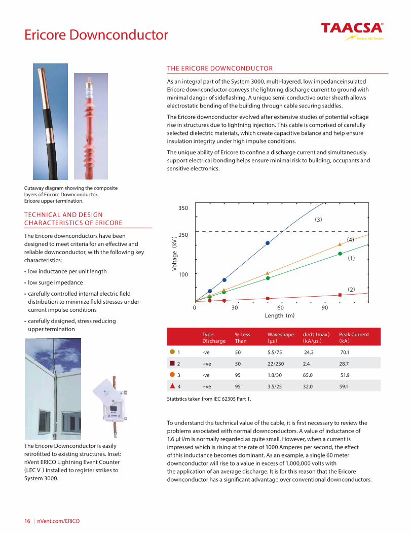
THE ERICORE DOWNCONDUCTOR
As an integral part of the System 3000, multi-layered, low impedanceinsulated Ericore downconductor conveys the lightning discharge current to ground with minimal danger of side�ashing. A unique semi-conductive outer sheath allows electrostatic bonding of the building through cable securing saddles.
The Ericore downconductor evolved after extensive studies of potential voltage rise in structures due to lightning injection. This cable is comprised of carefully selected dielectric materials, which create capacitive balance and help ensure insulation integrity under high impulse conditions.
The unique ability of Ericore to con�ne a discharge current and simultaneously support electrical bonding helps ensure minimal risk to building, occupants and sensitive electronics.
TECHNICAL AND DESIGN CHARACTERISTICS OF ERICORE
The Ericore downconductors have been designed to meet criteria for an e�ective and reliable downconductor, with the following key characteristics:
• low inductance per unit length
• low surge impedance
• carefully controlled internal electric �eld distribution to minimize �eld stresses under current impulse conditions
• carefully designed, stress reducing upper termination
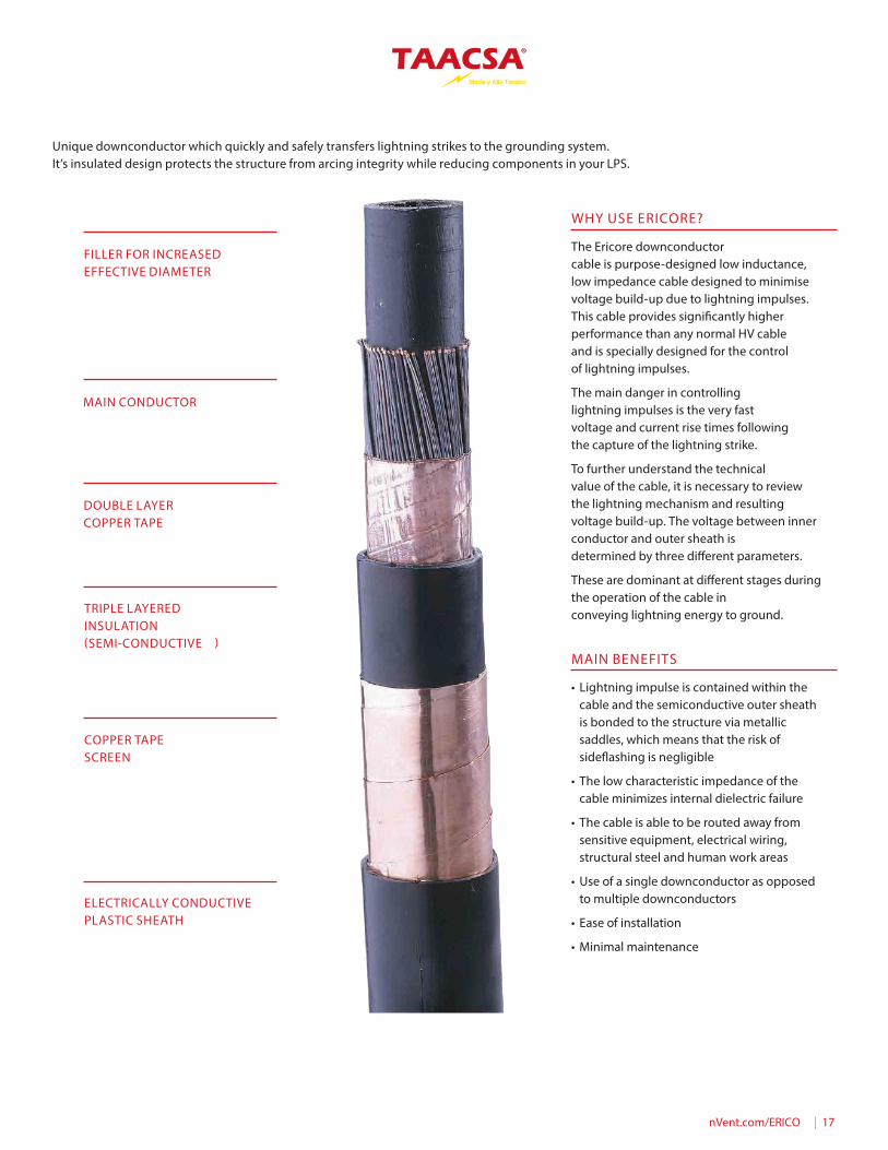
To understand the technical value of the cable, it is �rst necessary to review the problems associated with normal downconductors. A value of inductance of 1.6 µH/m is normally regarded as quite small. However, when a current is impressed which is rising at the rate of 1000 Amperes per second, the e�ect of this inductance becomes dominant. As an example, a single 60 meter downconductor will rise to a value in excess of 1,000,000 volts with the application of an average discharge. It is for this reason that the Ericore downconductor has a signi�cant advantage over conventional downconductors.
Volta
ge (
kV) 250
Type Discharge
% Less Than
Waveshape (µs )
di/dt (max ) (kA/µs )
Peak Current (kA )
1 -ve 50 5.5/75 24.3 70.1
2 +ve 50 22/230 2.4 28.7
3 -ve 95 1.8/30 65.0 51.9
4 +ve 95 3.5/25 32.0 59.1
Cutaway diagram showing the composite layers of Ericore Downconductor. Ericore upper termination.
The Ericore Downconductor is easily retro�tted to existing structures. Inset: nVent ERICO Lightning Event Counter (LEC V ) installed to register strikes to System 3000.
(3)
(4)
(1)
(2)
Length (m)
100
0 30 60 90
350
Statistics taken from IEC 62305 Part 1.
Ericore Downconductor
nVent.com/ERICO | 17
WHY USE ERICORE?
The Ericore downconductor cable is purpose-designed low inductance, low impedance cable designed to minimise voltage build-up due to lightning impulses. This cable provides signi�cantly higher performance than any normal HV cable and is specially designed for the control of lightning impulses.
The main danger in controlling lightning impulses is the very fast voltage and current rise times following the capture of the lightning strike.
To further understand the technical value of the cable, it is necessary to review the lightning mechanism and resulting voltage build-up. The voltage between inner conductor and outer sheath is determined by three di�erent parameters.
These are dominant at di�erent stages during the operation of the cable in conveying lightning energy to ground.
MAIN BENEFITS
• Lightning impulse is contained within the cable and the semiconductive outer sheath is bonded to the structure via metallic saddles, which means that the risk of side�ashing is negligible
• The low characteristic impedance of the cable minimizes internal dielectric failure
• The cable is able to be routed away from sensitive equipment, electrical wiring, structural steel and human work areas
• Use of a single downconductor as opposed to multiple downconductors
• Ease of installation
• Minimal maintenance
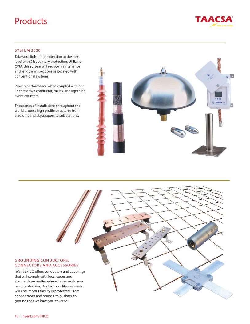
FILLER FOR INCREASED EFFECTIVE DIAMETER
MAIN CONDUCTOR
DOUBLE LAYER COPPER TAPE
TRIPLE LAYERED INSULATION (SEMI-CONDUCTIVE )
COPPER TAPE SCREEN
ELECTRICALLY CONDUCTIVE PLASTIC SHEATH
Unique downconductor which quickly and safely transfers lightning strikes to the grounding system. It’s insulated design protects the structure from arcing integrity while reducing components in your LPS.
18 | nVent.com/ERICO
Products
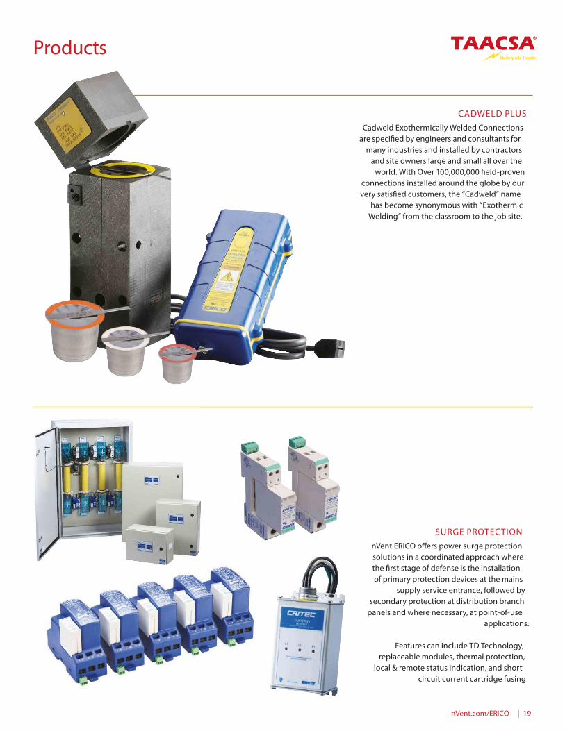
SYSTEM 3000Take your lightning protection to the next level with 21st century protection. Utilizing CVM, this system will reduce maintenance and lengthy inspections associated with conventional systems.
Proven performance when coupled with our Ericore down conductor, masts, and lightning event counters.
Thousands of installations throughout the world protect high pro�le structures from stadiums and skyscrapers to sub stations.
GROUNDING CONDUCTORS, CONNECTORS AND ACCESSORIESnVent ERICO o�ers conductors and couplings that will comply with local codes and standards no matter where in the world you need protection. Our high quality materials will ensure your facility is protected. From copper tapes and rounds, to busbars, to ground rods we have you covered.
nVent.com/ERICO | 19
CADWELD PLUSCadweld Exothermically Welded Connections
are speci�ed by engineers and consultants for many industries and installed by contractors
and site owners large and small all over the world. With Over 100,000,000 �eld-proven
connections installed around the globe by our very satis�ed customers, the “Cadweld” name
has become synonymous with “Exothermic Welding” from the classroom to the job site.
SURGE PROTECTIONnVent ERICO o�ers power surge protection solutions in a coordinated approach where the �rst stage of defense is the installation of primary protection devices at the mains
supply service entrance, followed by secondary protection at distribution branch
panels and where necessary, at point-of-use applications.
Features can include TD Technology, replaceable modules, thermal protection,
local & remote status indication, and short circuit current cartridge fusing
Products
www.taacsa.com
[email protected] | 999 30 59 300
| 999 36 84 776
TAACSA® empresa certi�cada en Calidad ISO 9001. La ceriti�cación no extendible a productos descritos.Las imágenes son ejemplos ilustrativos.
EN LA ATENCIÓNAL CLIENTE
CALIDAD