NV-series PT Simple Operation Preparation Handbook
36
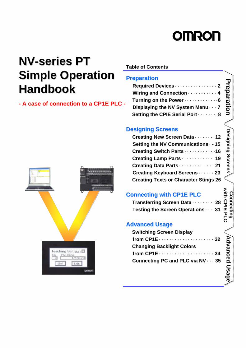
Advanced Usage Advanced Usage Connecting with CPIE PLC Connecting with CPIE PLC Designing Screens Designing Screens Preparation Preparation NV NV - - series PT series PT Simple Operation Simple Operation Handbook Handbook - A case of connection to a CP1E PLC - Table of Contents Preparation Preparation Required Devices ⋅⋅⋅⋅⋅⋅⋅⋅⋅⋅⋅⋅⋅⋅⋅⋅ 2 Wiring and Connection ⋅⋅⋅⋅⋅⋅⋅⋅⋅⋅⋅ 4 Turning on the Power ⋅⋅⋅⋅⋅⋅⋅⋅⋅⋅⋅⋅⋅6 Displaying the NV System Menu ⋅⋅⋅ 7 Setting the CPIE Serial Port ⋅⋅⋅⋅⋅⋅⋅⋅8 Designing Screens Designing Screens Creating New Screen Data ⋅⋅⋅⋅⋅⋅⋅ 12 Setting the NV Communications ⋅ ⋅⋅15 Creating Switch Parts ⋅⋅⋅⋅⋅⋅⋅⋅⋅⋅⋅⋅16 Creating Lamp Parts ⋅⋅⋅⋅⋅⋅⋅⋅⋅⋅⋅⋅ 19 Creating Data Parts ⋅⋅⋅⋅⋅⋅⋅⋅⋅ ⋅⋅⋅⋅ 21 Creating Keyboard Screens ⋅⋅⋅⋅⋅⋅ 23 Creating Texts or Character Stings 26 Connecting with CP1E PLC Connecting with CP1E PLC Transferring Screen Data ⋅⋅⋅⋅⋅⋅⋅⋅ 28 Testing the Screen Operations ⋅⋅⋅⋅31 Advanced Usage Advanced Usage Switching Screen Display from CP1E ⋅⋅⋅⋅⋅⋅⋅⋅⋅⋅⋅⋅⋅⋅⋅⋅⋅⋅⋅⋅⋅ 32 Changing Backlight Colors from CP1E ⋅⋅⋅⋅⋅⋅⋅⋅⋅⋅⋅⋅⋅⋅⋅⋅⋅⋅⋅⋅⋅ 34 Connecting PC and PLC via NV ⋅⋅⋅ 35
Transcript of NV-series PT Simple Operation Preparation Handbook
Advanced U
sageA
dvanced Usage
Connecting
with C
PIE PLCC
onnecting w
ith CPIE PLC
Designing Screens
Designing Screens
PreparationPreparation
NVNV--series PTseries PTSimple Operation Simple Operation HandbookHandbook- A case of connection to a CP1E PLC -
Table of Contents
PreparationPreparationRequired Devices ⋅ ⋅ ⋅ ⋅ ⋅ ⋅ ⋅ ⋅ ⋅ ⋅ ⋅ ⋅ ⋅ ⋅ ⋅ ⋅ 2Wiring and Connection ⋅ ⋅ ⋅ ⋅ ⋅ ⋅ ⋅ ⋅ ⋅ ⋅ ⋅ 4Turning on the Power ⋅ ⋅ ⋅ ⋅ ⋅ ⋅ ⋅ ⋅ ⋅ ⋅ ⋅ ⋅ ⋅6Displaying the NV System Menu ⋅ ⋅ ⋅ 7Setting the CPIE Serial Port ⋅ ⋅ ⋅ ⋅ ⋅ ⋅ ⋅ ⋅8
Designing ScreensDesigning ScreensCreating New Screen Data ⋅ ⋅ ⋅ ⋅ ⋅ ⋅ ⋅ 12Setting the NV Communications ⋅ ⋅⋅15Creating Switch Parts ⋅ ⋅ ⋅ ⋅ ⋅ ⋅ ⋅ ⋅ ⋅ ⋅ ⋅ ⋅16Creating Lamp Parts ⋅ ⋅ ⋅ ⋅ ⋅ ⋅ ⋅ ⋅ ⋅ ⋅ ⋅ ⋅ 19Creating Data Parts ⋅ ⋅ ⋅ ⋅ ⋅ ⋅ ⋅ ⋅ ⋅ ⋅ ⋅ ⋅ ⋅ 21Creating Keyboard Screens ⋅ ⋅ ⋅ ⋅ ⋅ ⋅ 23Creating Texts or Character Stings 26
Connecting with CP1E PLCConnecting with CP1E PLCTransferring Screen Data ⋅ ⋅ ⋅ ⋅ ⋅ ⋅ ⋅ ⋅ 28Testing the Screen Operations ⋅ ⋅ ⋅ ⋅31
Advanced UsageAdvanced UsageSwitching Screen Displayfrom CP1E ⋅ ⋅ ⋅ ⋅ ⋅ ⋅ ⋅ ⋅ ⋅ ⋅ ⋅ ⋅ ⋅ ⋅ ⋅ ⋅ ⋅ ⋅ ⋅ ⋅ ⋅ 32Changing Backlight Colors from CP1E ⋅ ⋅ ⋅ ⋅ ⋅ ⋅ ⋅ ⋅ ⋅ ⋅ ⋅ ⋅ ⋅ ⋅ ⋅ ⋅ ⋅ ⋅ ⋅ ⋅ ⋅ 34Connecting PC and PLC via NV ⋅ ⋅ ⋅ 35

2
These are the equipment and devices required to connect an NV-series PT to a CP1E PLC.
Required DevicesRequired Devices
CP1E-NxxDxx-xN type (Application model)
-RS-232C type (24 VDC) NV3Q-MR21 NV3Q-SW21
-RS-422A type (24 VDC) NV3Q-MR41 NV3Q-SW41
Power Supply for Programmable Terminals・For a NV3W (24 VDC type), NV4W or NV3Q, use a 24-VDC power supply unit for it.・Power supply unit is not necessary for NV3W RS-232C type (5VDC type), since 5VDC is
supplied from PLC via the cable (XW2Z-200T-4).
PT: NV-series
PLC: CP1E-series
Compact Horizontal Models:NV3W (3.1 inch)
-RS-232C type (5 VDC) NV3W-MR20L NV3W-MG20L
-RS-232C type (24 VDC) NV3W-MR20 NV3W-MG20
-RS-422A type (24 VDC) NV3W-MR40 NV3W-MG40
QVGA Models:NV3Q (3.6 inch)
Package PLCs with Exceptional Cost : CP1E
Three color LED backlight of white, pink and redNV3W-MRxx(x)
Three color LED backlight of green, orange and redNV3W-MGxx(x)
Three color LED backlight of white, pink and redNV3Q-MRxx
STN color (Display colors : 4096 colors)NV3Q-SWxx
-RS-232C type (5 VDC) XW2Z-200T-4 (2m with 5-V Line)
-RS-232C type (24 VDC)XW2Z-200T-3 (2m without 5-V Line)XW2Z-500T-3 (5m without 5-V Line)
-RS-422A type (24 VDC)Prepare one by referring to the Manual.
PT-to-PLC Connecting Cable
Compact Horizontal Models:NV4W (4.6 inch)
-RS-232C type (24 VDC)NV4W-MR21 NV4W-MG21
-RS-422A type (24 VDC)NV4W-MR41 NV4W-MG41
Three color LED backlight of white, pink and redNV4W-MRxx
Three color LED backlight of green, orange and redNV4W-MGxx
Note: E-type CP1E CPU Units (Basic Models) can not be used with NV Series PT, since they do not have RS-232C port.

3
NV-series PT Simple Operation Handbook
Advanced U
sageA
dvanced Usage
Connecting w
ith CPIE
Connecting w
ith CPIE
Designing Screens
Designing Screens
PreparationPreparation
FA Integrated Tool Package
•CX-One Lite Ver.4.x (4.03 or higher)CX-One Lite is a subset of the complete CX-One package that provides only the Support Software required for micro PLC applications.
•CX-One Ver.4.x (4.03 or higher)CX-One is a package that integrates the Support Software for OMRON PLCs and components.
♦ Selective from the two in below.Included in both packages of CX-One Lite Ver.4 and CX-One Ver.4.* It cannot be purchased individually.• NV-Designer Ver.1.1
Screen designing software for NV
Programming software for PLC
Included in a package of CX-One Lite Ver.4. It can be purchased individually.• Micro PLC Edition CX-Programmer Ver.9.
Included in a package of CX-One Ver.4.It can be purchased individually.• CX-Programmer Ver.9
♦ Selective from these:
NV-PC connection cable
NV3WNV3W
NV3Q
PC•Use a commercially available USB cable.
CP1E PLC-PC connection cable
♦Use the Special Cable (NV-TOL-3M) to connect the NV3W to a PC. When the PC does not have a RS-232C serial port, use a USB-serial conversion cable (CS1W-CIF31) as well.
♦Use a commercially available USB cable (Mini-B) to connect the NV4W to a PC.Use a commercially available USB cable (Type B) to connect the NV3Q to a PC.
CP1E
Connecting an NV3W to USB port on PC
•NV-TOL-3M + CS1W-CIF31 •NV-TOL-3M
Connecting an NV3Q •Use a commercially available USB cable (Type B) .
Type B※Prepare at least one USB cable. It can be used to connect
the NV to the CP1E PLC or to the PC alternatively.
PreparationPreparation
Connecting an NV3W to RS-232C serial port on PC
NV4W
Connecting an NV4W
Mini-B Type A
•Use a commercially available USB cable (Mini-B).
Type A
Type B Type A
*Supporting Windows 7
(32 bit version) !

4
Wiring and ConnectionWiring and ConnectionConnect the devices.* This section explains the procedure to connect an NV3W (5-VDC type) PT to a CP1E PLC.
Connecting Example
CS1W-CIF31 + NV-TOL-3M
Commercially available USB cable(Type A connector – Type B connector)
XW2Z-200T-4(2m, with 5V Line)
Connecting the NV and CP1E
Connecting an NV3W (5-VDC type) PT to the USB port on PC
5V power (green)
Name (color)
RD (orange)SD (blue)
SG (pink)
NV3W (5-VDC)
※The NV3W of 5-VDC type does not need a power supply unit. The 5-V power is supplied from PLC through the XW2Z-200T-4 Special Cable.
NV3W –MR20L
PC
CP1E-N20DR-A
Wiring for CP1E AC power supply
Wire for the CP1E AC power supply.
Connect the NV and the CP1E with the XW2Z-200T-4 Special Cable.
FG (black)
Ground to 100 ohm or less
XW2Z-200T-4Special Cable
(2m,with 5V Line)
Upper terminal block
100 to 240 VAC, 50/60Hz
5
NV-series PT Simple Operation Handbook
Advanced U
sageA
dvanced Usage
Connecting w
ith CPIE
Connecting w
ith CPIE
Designing Screens
Designing Screens
PreparationPreparation
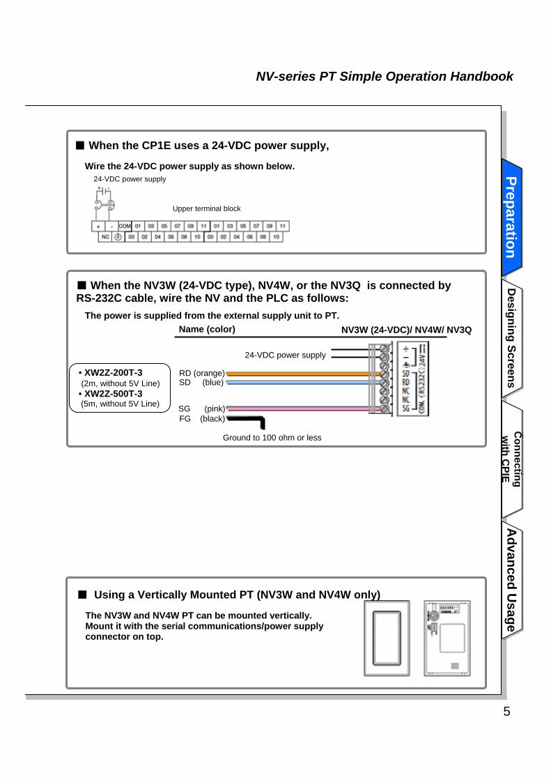
The NV3W and NV4W PT can be mounted vertically.Mount it with the serial communications/power supply connector on top.
■ Using a Vertically Mounted PT (NV3W and NV4W only)
■ When the CP1E uses a 24-VDC power supply,
Wire the 24-VDC power supply as shown below.
• XW2Z-200T-3(2m, without 5V Line)• XW2Z-500T-3(5m, without 5V Line)
■ When the NV3W (24-VDC type), NV4W, or the NV3Q is connected by RS-232C cable, wire the NV and the PLC as follows:
The power is supplied from the external supply unit to PT.Name (color)
RD (orange)SD (blue)
SG (pink)
NV3W (24-VDC)/ NV4W/ NV3Q
FG (black)
Ground to 100 ohm or less
24-VDC power supply
Upper terminal block
24-VDC power supply PreparationPreparation

6
Turning on the PowerTurning on the PowerTurn on the power to the CP1E. The power is also supplied to NV through the RE-232C serial port on the CP1E.
If you turn ON the power to NV after you change the DIP switch pins on the NV back face to any setting other than the factory setting, the NV starts up in a special operation mode. You can use the functions to prohibit accessing the System Menu and to clear the F-ROM. Do not use the NV in any settings other than shown below.
Normal operation (factory setting)
Prohibiting moving to System Menu F-ROM clear
Note1: The data saved in the F-ROM includes screen data and NV configuration data.Note2: Other than the DIP switch setting, you can clear the F-ROM from the System Menu.
Turning ON the power to CP1E
NV startup mode
Turn ON the power to the CP1E. The POWER LED indicator on the front of CP1E lights in green. The NV screen shows a message as follows:
Note: The message “No Screen data” is shown when the NV has no screen data. As the NV contains no data at factory shipping, the message is shown accordingly.
Turn OFF all pins. Turn ON pin 2. Turn ON pins 2, 3,and 4.
POWERLED
XW2Z-200T-4

7
NV-series PT Simple Operation Handbook
Advanced U
sageA
dvanced Usage
Connecting w
ith CPIE
Connecting w
ith CPIE
Designing Screens
Designing Screens
PreparationPreparation
Displaying the NV System MenuDisplaying the NV System MenuThe System Menu is the special screen that is used to configure the NV. Some settings such as touch switch adjustment can only be done on the System Menu.
Accessing the System Menu
Follow the steps below to access the System Menu.
1. Touch the touch panel on the PT as shown below.(This is common for entire NV-series.)
The startup screen of the System Menu will be displayed.The next screen will be displayed if you touch the Setting or Test Key. To return to normal operating status, touch the ESC Key.
Changing the System Menu Language.・On the NV3W, the language changes to the one set by System Language (either English
or Japanese) option for the transferred screen data. Thus transferring the screen data enables the language setting. *The language is not switchable on the NV System Menu.
・On the NV4W or NV3Q , the language is switchable between English and Japanese on the NV System Menu.
PreparationPreparation
1) Touch the upper left corner (A) for at least 2 seconds.
2) Then immediately touch the upper right corner (B) and lower right corner (C) in order.
Touch the A for at least 2 seconds, then press B and C in order.
Note: Touch A for 2 s and then B and C in order. Touch points A, B, and C one at a time in order. Do not press these switches at the same time. They must be pressed in order.
2. The startup screen of the System Menu will be displayed.The default language for the System Menu is English, if there is no screen data in the PT.The System Menu depends on the model of PT. The default System Menu for the NV3W is used here.
Note: The system version is the version of the system ROM in the PT.

8
Setting the CP1E Serial Port Setting the CP1E Serial Port To have the NV and the CP1E communications, the both serial ports must have the same setting. Use the PLC programming tool or CX-Programmer to set the communications standard on the CP1E.
Be sure to change the Stop Bit on the PLC from the default 2 to 1.The stop bit for the NV serial communications is fixed to 1 . Therefore, the stop bit of the PLC serial port must be changed from the default 2 to 1.
NV-CP1E communications setting exampleBoth the NV and the CP1E support the high speed communication of 115,200 bps. Connect them in this baud rate.Set the RS-232C serial ports on both of the NV and the CP1E as follows:
・Mode: Host Link・Baud rate: 115,200 bps・Data length: 7・Stop bit: 1・Parity bit: Even
Communications setting for RS-232C serial port built in the CP1E
Use the PLC programming tool or the CX-Programmer. Follow the steps below to set the RS-232C serial port built in the CP1E.
Connect the CX-Programmer and the CP1E online using a USB cable.
Change the CP1E operation mode to “Programming” (Stop).
Upload the PLC settings (including the built-in RS-232C serial port setting)
from CP1E.
Set the built-in RS-232C serial port on the PLC settings.
Write the PLC settings (including the built-in RS-232C serial port setting) into
the CP1E.
Turn OFF and then ON the power of the CP1E.
(The settings are reflected only after the power is turned ON.)
11
22
33
44
55
66
Note: Communications may be enabled, even when the stop bit on the PLC is 2 while the bit on the NV is 1. However, be sure to align the both in 1.
*After this setting is completed, turn OFF and then ON the power of the CP1E.

9
NV-series PT Simple Operation Handbook
Advanced U
sageA
dvanced Usage
Connecting w
ith CPIE
Connecting w
ith CPIE
Designing Screens
Designing Screens
PreparationPreparation
Online connection of CX-Programmer and CP1E
1. Start up the CX-Programmer. On the Windows Start menu, select Program – OMRON –CX-One – CX-Programmer – CX-Programmer.
2. On the menu bar, select PLC – Auto Online – Direct Online.
3. In the Direct Online dialog box, select the USB Connection for the PC – PLC (CP1E) connection type. Click the Connect Button.
Connection Type:Select either the Serial connection or the USB connection.
1) Click the No button.* Click the Yes button to upload the
program to the PC.
4. When the PC is connected with the CP1E, a new project will start.
PreparationPreparation

10
Changing the CP1E operation mode into Program
1. On the menu bar, select the PLC – Operation Mode – Program.
1) Confirm that stopping the ladder program do not cause any problem. Click the Yes button.
2. The CP1E operation mode changes to the Program.
The “Stopped” sign shows.
The “Program Mode” sign shows.
Transferring, setting and writing the PLC settings
1. Double-click the Settings in the project tree.
Double-click!!

11
NV-series PT Simple Operation Handbook
Advanced U
sageA
dvanced Usage
Connecting w
ith CPIE
Connecting w
ith CPIE
Designing Screens
Designing Screens
PreparationPreparation
3. On the menu bar, select the Option – Transfer to PLC.
Click!!
It is not selectable, when the PLC operation mode is not in Program mode.
1) Do not check.
2) Click the Yes button.
2. The PLC System Setting menu shows. On the menu, select the Option – Transfer from PLC.
The second value from the left of parameter is the stop bit. Be sure to set it to “1” when the PLC is connected to an NV.
Click!!
Click!!
2. The PLC setting for the CP1E is uploaded. to the PC. Make the setting on the built-in RS-232C Port tab as follows.
Turning OFF and then ON the power of the CP1E
1. Turn OFF and then ON the power of the CP1E. The RS-232C serial port setting becomes effective when the power is turned ON. This completes the CP1E communications setting.
PreparationPreparation

12
Creating New Screen DataCreating New Screen DataThe NV communications setting is set by transferring the screen data to the NV.Create a screen data by using the screen designing software, NV-Designer.
Starting up the NV-Designer and creating new projects
1. On the Windows Start menu, select Program – OMRON – CX-One – NV-Designer -NV-Designer.
3. On the Select Model dialog Box, select the NV Model and the NV Type. Enter a project name in the File Name field. Click the Next button.
NV Model:Select the model of NV.
2. After the NV-Designer starts up, the NV-Designer dialog box will show. Select the Create New Project option button. Click the OK button.
NV Type:Select one from monochrome, color and vertical.File Name:Enter a project file name. In the left example, a file “New Project. nvp”and a folder “New Project” are created.

13
NV-series PT Simple Operation Handbook
Advanced U
sageA
dvanced Usage
Connecting w
ith CPIE
Connecting w
ith CPIE
Designing Screens
Designing Screens
PreparationPreparation
4. Select the PLC Model to connect. Click the Next button.
PLC Model:Select the PLC model to connect.
5. In the System Memory Area field, set the Word Area and the Bit Area. Click the OK button.
As the Word Area, the areas of 3 words in series are occupied to read and write the data in units of words such as Screen No. As the Bit Area, the areas of 3 words in series are occupied to read and write the data in units of bits such as Backlight Light/Blink. In total 6 words are occupied.
the area used for the PLC to control the basic operations such as switching screens.The PLC area is steadily occupied and has constant communications.
System memory is:
Number of words occupied as the system memory
System Memory Area:Set the areas occupied and used for PLC to control the NV.
Note: The default address allocated to the bit area is “0”. As it corresponds to the CP1E input area, it must be changed to a program area such as Work Area.
Designing Screens
Designing Screens
Note: The address allocated to the system memory can be changed from the menu bar. Select PT – NV Configuration.

14
4. The Main Window of NV-Designer will show.In the Screen Manager, double-click the No. “0”. Then the Base Screen 0 and the Parts Library will show.
You can place texts and parts on this screen, and create a new screen.
Manu bar
Toolbar
Graphic bar
Base Screen Parts LibraryScreen Manager
Base Screen
Parts LibraryThis is the collection of parts such as switch, lamp, data display and keyboard.You can also create an original parts library, or customize it by registering only selected parts.
Screen Manager
This is used to manage the screens by their number. You can create a new base screen, and edit, copy, move and delete it. You can also open plural projects at the same time and copy and move a screen among the projects.
Double-click!!

15
NV-series PT Simple Operation Handbook
Advanced U
sageA
dvanced Usage
Connecting w
ith CPIE
Connecting w
ith CPIE
Designing Screens
Designing Screens
PreparationPreparation
Setting the NV CommunicationsSetting the NV CommunicationsSet the NV - CP1E communications as the screen data.
Setting the NV communications1. On the NV-Designer menu, select PT – NV Configuration.
Click!!
NV-CP1E communications setting exampleThe CP1E communications was set as follows: Set the same for the NV communications.
・Mode: Host Link・Baud rate: 115,200 bps・Data length: 7・Stop bit: 1・Parity bit: Even
The stop bit for the NV serial communications is fixed to 1.Therefore, the stop bit of the PLC serial port must be changed from the default 2 to 1.
2. Select the Communication Parameters tab. Set the communications with the CP1E.Click the OK button. Close the Dialog box. This completes the NV communication setting.
Click!!
Set these items for communications with CP1E.
Designing Screens
Designing Screens

16
Creating Switch PartsCreating Switch PartsThis and following few pages describe the procedure to create a part on the screen, and confirming the NV-CP1E operations. Firstly, create the switch part that turns ON and OFF the bit address in the PLC.
An example of creating switch partThis switch part turns on the bit 10.00 on the PLC when you press the switch, and turns off the bit 10.00 when you release it. (Momentary operation)
Normally it is OFF. While pressed it turns to ON.
Creating a switch part
Select a switch part from the library. Drag and drop it at any desired space on the base screen.
1) Use the Parts Library Standard (NV3W).
2) Use a part SW2.
Drag and drop!!
When pressed When released

17
NV-series PT Simple Operation Handbook
Advanced U
sageA
dvanced Usage
Connecting w
ith CPIE
Connecting w
ith CPIE
Designing Screens
Designing Screens
PreparationPreparation
Setting the function for the switch partDouble-click the switch part. Select the Basic Setup tab. Set the operation mode and the ON/OFF Indication of lamp in each field.
Operation Mode:It specifies the operation and the bit address in the PLC.
ON/OFF Indication (Lamp):Select either ON to switch the ON/OFF indication or OFF not to switch it. When you select ON, set also the switch timing.
Creating the switch label1. Select the Label tab.
ON / OFF:Set the label each when the
switch is ON and OFF.*Start with the OFF button.
Text:Enter a text or string to show.
Font:Set the front type and the position to show the text or string.
Size:Set the front size of the text or string.
Color:Set the text color and the background color.
Designing Screens
Designing Screens

18
2. Click the ON button. Click the COPY from OFF button. Then the setting When OFF is copied to ON. The two have the same setting.
1) Select the ON.
2) Click the COPY from OFF button.
Click!!
3. Change the character color for ON into white.After setting, click the OK button and close the setting dialog box. This completes creating a switch part.
1) Change the character color into white.
Confirming the part ON/OFF state by previewSelect the part. On the tool bar, select the Parts state. You can preview the on/off state of the selected parts.
Parts stateOFF (Normal) ON (When pressed)
1) Select a part.(You can select plural parts.)
2) Switch the ON/OFF state by Parts state.

19
NV-series PT Simple Operation Handbook
Advanced U
sageA
dvanced Usage
Connecting w
ith CPIE
Connecting w
ith CPIE
Designing Screens
Designing Screens
PreparationPreparation
Creating Lamp PartsCreating Lamp PartsThe lamp parts switch colors in accordance with the ON/OFF state of the corresponding bit address on the PLC.
An example of creating lamp part
The lamp changes color depending on the ON/OFF state of bit 10.00 on the PLC.
The lamp is colored in white when the bit 10.00 is OFF.It turns black when the bit 10.00 is ON.
Bit OFF Bit ON
Creating Lamp partsFrom the Parts Library, select a lamp part. Drag and drop it at any desired space on the base screen.
1) Use the Parts Library Standard (NV3W).
2) Use the part Lamp0.
Drag and drop!!
Designing Screens
Designing Screens

20
Setting the function for the lamp partDouble-click the lamp part. Select the Basic Setup tab. Set the bit address in the ON/OFF Bitfield. Click the OK button and close the dialog box. This completes creation of lamp part.
ON /OFF Bit: Set the bit address of the PLC.

21
NV-series PT Simple Operation Handbook
Advanced U
sageA
dvanced Usage
Connecting w
ith CPIE
Connecting w
ith CPIE
Designing Screens
Designing Screens
PreparationPreparation
Creating Data PartsCreating Data PartsCreate a data part which indicates a value in a PLC address in a numeric value or a character string. Data parts can be used for indication only (no entries allowed) or for changing the values from the Keyboard Screen as well.
An example of creating Data PartsThis data part indicates the PLC address of D100 in a decimal number.Clicking the part changes the screen to the Keyboard. Enter a value on the keyboard and change the value for the D100 address.
Creating Data parts
From the Parts Library, select a data part. Drag and drop it at any desired space on the base screen.
1) Use the Parts Library Standard (NV3W).
2) Use the part Data.Drag and drop!!
It changes to the Keyboard Screen. Enter a numeric valuePress the part
Designing Screens
Designing Screens

22
Setting the function for the data partDouble-click the data part. Select the Basic Setup tab. Note: This example uses the default setting.
Address:Set the PLC word address.
Data to Display: Set the Number of Digits, the
Data Format and the Zero Suppression.
Note: Select “ASCII” for the format when the data is indicated or entered as a character string.
Setting to enable or disable the inputs and other setting itemsClick the Input tab. Select the option button On. Set the input method in other fields. Click the OK button to lose the setting dialog box. This completes the data part setting.
Supported Keyboard:Set the input method to the keyboard.・Keyboard Screen:
Input after switching to the Keyboard Screen.
・Keyboard part:Input from the keyboard part that is on the same screen as the data part.
Input:Select either On to enter values from the screen or Off not to do it.Note: When the Off is selected, the screen is for indication only (no entries allowed).
Startup Condition:Select the value input timing. ・Conditions
When the specified bit address satisfies the conditions, the data part enables inputs.

23
NV-series PT Simple Operation Handbook
Advanced U
sageA
dvanced Usage
Connecting w
ith CPIE
Connecting w
ith CPIE
Designing Screens
Designing Screens
PreparationPreparation
Creating Keyboard ScreensCreating Keyboard ScreensCreate a Keyboard Screen to enter a data for the data parts.
Creating a Keyboard Screen1. On the menu bar, select File – Keyboard Screen.
Click!!
2. On the Edit Keyboard Screen dialog box, select the screen No.0. Click the Draw button. Then the Keyboard Screen No.0 opens.
Click!!
An example of creating keyboard screen
On this Keyboard Screen, you can enter decimal values and signs. Also you can confirm the values entered from the keyboard before they are entered.
Designing Screens
Designing Screens

24
Choosing a keyboard part.From the Parts Library, select a keyboard part. Drag and drop it at any desired space on the keyboard screen.
1) Use the Parts Library Standard (NV3W).
3) Use the part DEC Sign1.
Drag and drop!!
2) Use the part typeKeyboard.
*A window opens for each part type.
Setting the function for the keyboard partDouble-click the keyboard part. Select the Basic Setup tab. Make a necessary setting as shown below. Note: This example uses the default setting. Click the OK button and close the setting dialog box.
Image: The setting can be confirmed here.Clicking a key part will show the key setting dialog box. Enter a value on the box. You can set a value for each key.
Number of keys:Set the vertical (line) and horizontal (row) number of keys.
Keyboard Replacement:Keyboard keys are selective among upper case, lower case and alphanumerical & symbols. When the Change the Keyboard (On) is selected, set the value to change from 1-8.
Click!!

25
NV-series PT Simple Operation Handbook
Advanced U
sageA
dvanced Usage
Connecting w
ith CPIE
Connecting w
ith CPIE
Designing Screens
Designing Screens
PreparationPreparation
Choosing a data partChoose and place a data part to show the value entered in the screen.From the Parts Library, select a data part. Drag and drop it at any desired space on the keyboard screen.
1) Use the Parts Library Standard (NV3W).
3) Use the part Data.
Drag and drop!!
2) Use the part typeData.
Setting the function for the data partSet the function for the data part. Note: This example uses the default setting. Click the OK button and close the setting dialog box. This completes creating a keyboard screen.
Data to Display:Set the digit number to display.
Designing Screens
Designing Screens

26
Creating Texts or Character StringsCreating Texts or Character StringsThis section explains the procedures to show texts or character strings on a screen. It also describes how to change the character attributes such as font, size and color. This way, the character string will stand out.
Example of drawing text
In this example, the character string “Value” is outlined.
Creating a text or a character string1. On the graphic bar, click the
Character String icon.2. On the base screen, click a position
to show a character string.
3. Enter a text string. 4. On the graphic bar, click the Character Type icon.
5. The Character Attributes dialog box will show. Check the box for Outlined. Click the OK button and close the setting dialog box. This completes creating a character string.
Click!!NEXT
NEXT

27
NV-series PT Simple Operation Handbook
Advanced U
sageA
dvanced Usage
Connecting w
ith CPIE
Connecting w
ith CPIE
Designing Screens
Designing Screens
PreparationPreparation
■ To show a picture image such as bitmap on the NV screen:
The NV-series PTs can display a picture images such as bitmap images.You can transfer to and paste the images on the NV by copying them on the Windows clip board.
1. On the workspace of graphic software such as MS Paint, open an image file to show on the NV.
2. Select the range of the image to show on the NV and copy it.
<MS Paint>1) Select the range.
(Press Ctrl + A for select all)2) Right-click the image, and
select Copy from the context menu. Alternatively, pressCtrl + C and copy the image on the clip board.
3. On the NV-Designer, open the screen to paste the image. Right-click and select Past from the context menu. Alternatively, press Ctrl + V to past the image.
Right-Click!! 1) Select Past.
Note: Any images or pictures larger than the display resolution (for NV3W, 128 w x 64 h, and for NV3Q, 320 w x 240 h) cannot be pasted. Scale down the images to any sizes smaller than the resolution, before you past them.
Right-click!!
Designing Screens
Designing Screens

28
Transferring Screen DataTransferring Screen DataTransfer the created screen data to the NV.
Setting the transfer method
1. On the menu bar, select PT – Transfer – Transfer.
Click!!
2. On the Data Transfer dialog box, set the communications with the PT as follows:Select the option button RS-232C serial in the Communication Method field. Click the Communications Setting button. On the Communication Parameters dialog box, select the PC COM port No. in the Port Number for RS-232C serial. Click the OK button and close the Communication Parameters dialog box.
Click!! 2) Click Communication Setting button.
1) Communication Method:Select RS-232C serial. Note: Select also RS-232C serial
when the CS1W-CIF31 and the RS-232C / USB conversion are used.
When you use a NV4W or NV3Q PT,Select the option button USB as the communication method.
3) Set the PC COM port No. in the Port Number field.
Note: The COM port No. can be confirmed by the device manager.

29
NV-series PT Simple Operation Handbook
Advanced U
sageA
dvanced Usage
Connecting w
ith CPIE
Connecting w
ith CPIE
Designing Screens
Designing Screens
PreparationPreparation
Transferring the screen data1. Set the transfer direction and data to transfer. Then transfer the data to the NV.
1) Direction:Select the option button forNV-Designer NV.
2) Data to Transfer:Check the box for All Data.
3) Click the OK button to start transferring. The Transfer Data dialog box closes.
Click!!
■ Shortcut Ctrl + TTransfer is a frequently used operation. Use the shortcut for your convenience.
Transfer Data After Clear NV Screen:When the box is checked, the data is transferred to the NV after the flash memory of the NV is all cleared.When the box is not checked, the data is transferred into the unused area of the flash memory of the NV. The area which has already the transferred data will be invalid, and cannot be used until it is cleared next time. This method requires less transfer time.When the message “Memory is full” is shown on the screen, check this box and transfer the data.
Connecting
with C
PIE PLCC
onnecting w
ith CPIE PLC
2. When the transfer is completed, the screen is shown on the NV.
30
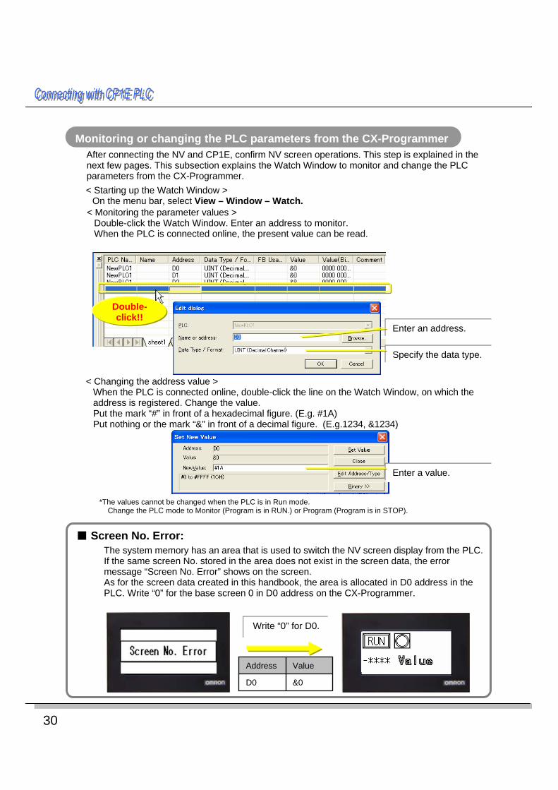
■ Screen No. Error:The system memory has an area that is used to switch the NV screen display from the PLC. If the same screen No. stored in the area does not exist in the screen data, the error message “Screen No. Error” shows on the screen. As for the screen data created in this handbook, the area is allocated in D0 address in the PLC. Write “0” for the base screen 0 in D0 address on the CX-Programmer.
Write “0” for D0.
Monitoring or changing the PLC parameters from the CX-ProgrammerAfter connecting the NV and CP1E, confirm NV screen operations. This step is explained in the next few pages. This subsection explains the Watch Window to monitor and change the PLC parameters from the CX-Programmer.< Starting up the Watch Window >
On the menu bar, select View – Window – Watch.
Double-click!!
Enter an address.
Enter a value.
< Monitoring the parameter values >Double-click the Watch Window. Enter an address to monitor.When the PLC is connected online, the present value can be read.
< Changing the address value >When the PLC is connected online, double-click the line on the Watch Window, on which the address is registered. Change the value. Put the mark “#” in front of a hexadecimal figure. (E.g. #1A)Put nothing or the mark “&” in front of a decimal figure. (E.g.1234, &1234)
Specify the data type.
*The values cannot be changed when the PLC is in Run mode.Change the PLC mode to Monitor (Program is in RUN.) or Program (Program is in STOP).
&0D0
ValueAddress

31
NV-series PT Simple Operation Handbook
Advanced U
sageA
dvanced Usage
Connecting w
ith CPIE
Connecting w
ith CPIE
Designing Screens
Designing Screens
PreparationPreparation
Testing the Screen OperationTesting the Screen OperationConfirm the part operation on an actual NV.
Checking the operation of switch and lamp parts
1. While you press the RUN switch 2. When you release your finger from the RUN switch
The lamp lights. The lamp goes off.
Confirming the operation of data parts and keyboard
When you touch a data part, the screen changes to the Keyboard. You can enter values.
Screen changes to Keyboard
Enter a numerical value.Touch a part.
If a power interruption persists over the I/O memory backup time, the values written in the CP1E data memory (or DM) from the NV are not held.To hold the data, use the DM function that operates the auxiliary area and backs up the data in the data memory (or DM) to the backup memory.
When a CP1E PLC is used in battery-free operation,
Connecting
with C
PIE PLCC
onnecting w
ith CPIE PLC

32
Switching Screen Display from CP1ESwitching Screen Display from CP1ESwitch the NV screen from the CP1E PLC by using its system memory.
Creating a new screen in an existing project
Add a base screen to an existing project. The screen is used to confirm the screen switching operation. 1. Start up the NV-Designer and open a project.
On the Screen Manager window, double-click the No. 1 to open the base screen 1.
Double-click!!
2. Enter a text (or character string) of “Base screen 1”. Align it at the center of the screen. Transfer the screen data to the NV.
Base screen 1

33
NV-series PT Simple Operation Handbook
Advanced U
sageA
dvanced Usage
Connecting w
ith CPIE
Connecting w
ith CPIE
Designing Screens
Designing Screens
PreparationPreparation
Setting and confirming the system memory1. On the menu bar, select PT – NV Configuration.
Click!!
2. Click the Basic Setup tab. In the System Memory Area field, you can set or confirm the assigned address.
Word area memory map (Head address = N )N: PLC specified screen No. (PLC NV)N+1: Use prohibitedN+2: Screen No. now in view (NV PLC)
Word area:- PLC specified screen No.Specify a screen No. to show on the NV. It is specified from the PLC in binary.
-Screen No. now in view Write the screen No. now in view on the NV. It is written to the PLC in binary.
Note: Cannot specify in BCD.
Switching screens from the CP1E PLC
1. Write “&0” for D0 address, and show the Screen0.
2. Write “&1” for D0 address, and show the Screen1.
When the screen switches, “&0” is notified to D2 address.
When the screen switches, “&1” is notified to D2 address.
On the CX-Programmer, overwrite the D0 value and switch the screens.
Advanced U
sageA
dvanced U
sage

34
Bit Area (Head address = N )* Extracted only the info related to the backlight.
N Bit10N Bit11N Bit12: Backlight Light (OFF)/Blink (ON)N Bit13: Backlight Control Enable Bit
(OFF): Bit10-12 settings are disabled.(ON): Bit 10-12 settings are enabled.
* When the Backlight Control Enable Bit is OFF, backlight is controlled following the settings for current screen.
The backlight is controlled following the backlight setting on the property of each base screen. (On the menu bar, select PT – Screen Property.) The backlight setting can be confirmed on the title bar of each base screen.
When the Backlight Control Enable Bit is OFF,
Changing Backlight Colors from CP1EChanging Backlight Colors from CP1EChange the backlight color from the CP1E system memory. *The model NV3Q-SWxx (color) can be set backlight ON and OFF only.
Setting and confirming the system memoryThe backlight is controlled in the bit area of the system memory.Open the Basic Setup tab on the NV Configuration. Check the addresses assigned in the Bit Area of the System Memory Area field.
Changing the backlight colors from the CP1EWith the CX-Programmer, operate the W0.10 to W0.13, and change the backlight status.Set the bits for backlight color and backlight Light/Blink and finally, turn on the Backlight Control Enable Bit. (This is the example of NV3W-MGxxx.)
Backlight colors. See the table below.
OnOnOnOffNV3Q-SWxx (Color)PinkRedWhiteOffNV3Q-MRxx (Monochrome)
PinkRedWhiteOffNV3W-MRxx(x) (Monochrome)NV4W-MRxx (Monochrome)
OrangeRedGreenOffNV3W-MGxx(x) (Monochrome)NV4W-MGxx (Monochrome)
Bit10=ONBit11=ON
Bit10=OFFBit11=ON
Bit10=ONBit11=OFF
Bit10=OFFBit11=OFFState of N Bit10 and Bit11
* Combination of backlight colors by NV models
Green lightW0.10: ONW0.11: OFFW0.12: OFFW0.13: ON
Red flashW0.10: OFFW0.11: ONW0.12: ONW0.13: ON
(E.g. :Red flash )

35
NV-series PT Simple Operation Handbook
Advanced U
sageA
dvanced Usage
Connecting w
ith CPIE
Connecting w
ith CPIE
Designing Screens
Designing Screens
PreparationPreparation
Connecting PC and PLC via NVConnecting PC and PLC via NVYou can transfer the ladder programs from the PC (or CX-Programmer) to the PLC through the NV to which both the PC and the PLC are connected. You can also monitor the programs from the PC through the NV.
A configuration exampleIn this configuration, you can transfer the ladder programs and monitor the PLC from the CX-Programmer through the NV.
PC
NV3W/NV4W/NV3Q
Host Link
SYSMAC - CS / CJ / CP-series
PC connection
cable
Setting1. On the CX-Programmer, open a project of a CS-, CJ- or CP-series PLC.
Double-click the New PLC in the project tree. The Change PLC dialog box shows.
Double-click!!
2. In the Network Type filed, select the NV type as specified below. Click the OK button.
⋅ NV3W NV-Thru (Serial Port)⋅ NV4W, NV3Q NV-Thru (USB Port)
3. Connect it online.
⋅ The CX-Programmer and the NV-Designer use the same serial port. Therefore, only one of them is online-connected with the NV at a time.
⋅ You can also connect the CX-Programmer with PLC through the NV by selecting PLC – Auto Online - Direct Connection from the PLC menu.
*The NV requires no setting.
Advanced U
sageA
dvanced U
sage

Authorized Distributor:
In the interest of product improvement, specifications are subject to change without notice.
Cat. No. V411-E1-01
© OMRON Corporation 2009 All Rights Reserved.
OMRON Corporation Industrial Automation Company
OMRON ELECTRONICS LLCOne Commerce Drive Schaumburg, IL 60173-5302 U.S.A.Tel: (1) 847-843-7900/Fax: (1) 847-843-7787
Regional HeadquartersOMRON EUROPE B.V.Wegalaan 67-69-2132 JD HoofddorpThe NetherlandsTel: (31)2356-81-300/Fax: (31)2356-81-388
Contact: www.ia.omron.comTokyo, JAPAN
OMRON ASIA PACIFIC PTE. LTD.No. 438A Alexandra Road # 05-05/08 (Lobby 2), Alexandra Technopark, Singapore 119967Tel: (65) 6835-3011/Fax: (65) 6835-2711
OMRON (CHINA) CO., LTD.Room 2211, Bank of China Tower, 200 Yin Cheng Zhong Road, PuDong New Area, Shanghai, 200120, ChinaTel: (86) 21-5037-2222/Fax: (86) 21-5037-2200 0110
Note: Do not use this document to operate the Unit.
![Ier Exam Preparation Pt Course Manual Blue Book[1]](https://static.fdocuments.in/doc/165x107/55cf98ec550346d0339a7bca/ier-exam-preparation-pt-course-manual-blue-book1.jpg)