NUVINCI OPTIMIZED CVP WITH HARMONY AUTOMATIC … · 1 en technical owner manual technical owner...
155
EN TECHNICAL OWNER MANUAL NUVINCI OPTIMIZED TM CVP WITH HARMONY AUTOMATIC SHIFT SYSTEM MANU-HRMY-00 EN DE 32-62 1-31 63-93 94-124 NL FR 125-155 ES
-
Upload
nguyentuyen -
Category
Documents
-
view
216 -
download
0
Transcript of NUVINCI OPTIMIZED CVP WITH HARMONY AUTOMATIC … · 1 en technical owner manual technical owner...
1
EN
TECHNICAL OWNER MANUAL
TECHNICAL OWNER MANUAL
NUVINCI OPTIMIZEDTM CVP WITH HARMONYAUTOMATIC SHIFT SYSTEM
MANU-HRMY-00
EN
DE32-62
1-31
63-93
94-124
NL
FR
125-155 ES

2
EN
TECHNICAL OWNER MANUAL
Table of contents
1. NuVinci Cycling products 3
1.1 Harmony 330TM, Harmony 380TM,
Harmony 380SETM, and Harmony H|SyncTM
Intelligent Drivetrains 3
1.2 The NuVinci OptimizedTM CVP 3
2. Harmony 330 operation & care 4
2.1 Harmony 330 System 4
2.2 Calibrating the Harmony 330 System 4
2.3 Upgrading the Harmony 330 System 4
3. Harmony 380 operation & care 5
3.1 Harmony 380/380SE System 5
3.2 Calibrating the Harmony 380/380SE System 5
4. Harmony H|SYNC operation & care 6
4.1 Harmony H|Sync System 6
4.2 Calibrating the Harmony
H|Sync System - General 6
4.3 Calibrating the Harmony
H|Sync System - Bosch Intuvia 7
5. Harmony general care 8
5.1 Disconnecting the Rear Wheel 8
5.2 Fitting the Rear Wheel 9
5.3 Cleaning & Lubrication 10
5.4 Wear Parts & Repair Work 10
6. Harmony assembly of components 11
6.1 Wheelbuilding 11
6.2 Installing the Sprocket 12
6.3 Installing the Input Speed Ring 13
6.4 Installing the Output Speed Ring 14
6.5 Installing the Hub Encoder
(Older Harmony Systems) 15
6.6 Harmony Hub Interface
Compatibility & Orientation 16
6.7 Installing the Harmony Hub Interface 17
6.8 Installing the Harmony H8TM Controller 18
6.9 Installing the Harmony H3TM Controller 18
6.10 Harmony Electrical Connections 19
7. Harmony service instructions 20
7.1 Servicing or Replacing Freewheel 20
7.2 Removing Brake Configurations 21
7.3 Installing Brake Configurations 22
8. Harmony technical data 23
8.1 CVP Specifications 23
8.2 Approved Gearing 24
8.3 Exploded View 25
8.4 CVP & Harmony Shifter Dimension 26
8.5 “Chain Only” and “Belt Compatible”
Harmony Systems 27
9. Intellectual property notice 28
10. Warranty 29
European Support and Service 31
North American Office 31

3
EN
TECHNICAL OWNER MANUAL
1.1 Harmony 330, Harmony 380/380SE , and Harmony H|Sync Intelligent Drivetrains
The Harmony series of intelligent drivetrain systems are the first continuously variable automatic shifting systems for bicycles.
The Harmony 330 system offers automatic-only shifting specifically for the NuVinci Optimized N330/N330f CVP.
The Harmony 380/380SE system offers both automatic and manual control options for NuVinci Optimized N360 and N380/N380SE series CVPs.
The Harmony H|Sync system is integrated completely with leading eBike drivetrain systems, utilizing the eBike user interface and allowing optimized interaction between the eBike and NuVinci Optimized N360 and N380/N380SE series CVPs.
1. NuVinci Cycling products
1.2 The NuVinci Optimized CVP
The NuVinci Optimized technology is a continuously variable planetary (CVP) drivetrain offering an infinite number of ratios inside its wide ratio range.Ratio changes occur within the hub smoothly via internals that are sealed for life and maintenance-free.
NUVINCI CYCLING PRODUCTS
The Nfinity series of mechanical shifting drivetrains are the first continuously variable systems for
bicycles, allowing the rider to control the ratio of NuVinci Optimized CVPs simply by rotating the
shifter grip.
Review the Nfinity online manual if your bicycle is configured with the Nfinity series of manual shift
systems

4
EN
TECHNICAL OWNER MANUAL
2. Harmony 330 operation & care
2.1 Harmony 330 System
• The Harmony 330 system is compatible only with the NuVinci Optimized N330/N330f CVP, and provides automatic shifting for the rider at all times.
• The Harmony 330 system utilizes the Harmony H3 controller (A), which makes automatic shifting as simple as pressing a button to choose your pedal cadence. The cadence settings (typically slow, medium or fast) are preset by the eBike manufacturer according to the bike and gearing specification.
A
HARMONY 330 OPERATION & CARE
2.2 Calibrating the Harmony 330 System
If the Harmony system has been reinstalled, or if system operation is inconsistent or incorrect, your Harmony 330 system may need to be calibrated.
To do this:
1. Turn system power on.
2. Pedal the bicycle lightly through the entire calibration procedure (preferably on a stand with the rear wheel off the ground).
3. On the Harmony H3 controller, press and hold the top and bottom buttons (B) simultaneously until the rear hub begins shifting (5-7 seconds typically), then release the buttons.
4. Continue pedaling lightly while the system shifts from “low” to “high” ratio multiple times and completes calibration.
2.3 Upgrading the Harmony 330 System
If the rider wishes to upgrade from the Harmony H3 controller to the Harmony H8 controller, it’s a simple “plug and play” installation. Contact your dealer or NuVinci Cycling service & support for more details.
B
The NuVinci Optimized CVP cannot be shifted completely through the ratio range when stationary. The Harmony
system will intelligently wait for pedaling or wheel movement if wide ratio ranges are commanded while stationary.
B
Top & Bottom Buttons
!
"Fast" Cadence Setting
"Medium" Cadence Setting
"Slow" Cadence Setting

5
EN
TECHNICAL OWNER MANUAL
3. Harmony 380/380SE operation & care
3.1 Harmony 380/380SE System
• The Harmony 380/380SE system is compatible with NuVinci Optimized N360 and N380/380SE series CVPs (but is incompatible with the NuVinci Optimized N330/N330f CVP).
• The Harmony 380/380SE system utilizes the Harmony H8 controller, which offers both fully automatic and manual shifting options. The rider switches between “automatic” and “manual” modes by pressing the “mode” button (A) on the H8 Controller housing.
• In automatic mode, Harmony 380/380SE automatically adjusts ratio to maintain the rider’s preferred cadence. The rider can choose their ideal cadence setting by rotating the grip. The blue LED “RPM” display indicates the cadence setting (B).
• In manual mode, the rider is able to shift on their own with “ride by wire” technology. Like the cable-shift system, the steeper the orange “hill” on the LED display (C), the easier the ratio for climbing.
3.2 Calibrating the Harmony 380/380SE System
If the Harmony system has been reinstalled, or if system operation is inconsistent or incorrect, your Harmony 380/380SE system may need to be calibrated.
To do this:
1. Turn system power on.
2. Pedal the bicycle lightly through the entire calibration procedure (preferably on a stand with the rear wheel off the ground).
3. On the Harmony H8 controller, press and hold the “mode” button (A) until the rear hub begins shifting (5-7 seconds typically), then release the button.
4. Continue pedaling lightly while the system shifts from “low” to “high” ratio multiple times and completes calibration.
HARMONY 380 OPERATION & CARE
The NuVinci Optimized CVP cannot be shifted completely through the ratio range when stationary. The
Harmony system will intelligently wait for pedaling or wheel movement if wide ratio ranges are commanded while stationary.
Mode button A
CManual shift mode
Easier ratio for climbing
BAutomatic shift mode
Faster pedal cadence setting
!
Slower pedal cadence settig
Faster ratio for speed

6
EN
TECHNICAL OWNER MANUAL
4.2 Calibrating the Harmony H|Sync System - General
If the Harmony system has been reinstalled, or if system operation is inconsistent or incorrect, your Harmony H|Sync system may need to be calibrated.
To do this:
1. Turn system power on.
2. Pedal the bicycle lightly through the entire calibration procedure (preferably on a stand with the rear wheel off the ground).
3. Initiate your eBike Harmony H|Sync calibration.
- If not represented in the following sections, reference your e-Bike system manual for Harmony H|Sync calibration instructions.
4. Continue pedaling lightly while the system
shifts from “low” to “high” ratio multiple times and completes calibration.
4. Harmony H|SYNC operation & care
4.1 Harmony H|Sync System
• The Harmony H|Sync system is com-patible with NuVinci Optimized N360 and N380/N380SE series CVPs (but is incompatible with the NuVinci Optimized N330/N330f CVP).
• The Harmony H|Sync system is integrated
with the eBike control system, and offers the potential for both automatic and ma-nual shift modes.
• In automatic mode, Harmony H|Sync automatically adjusts ratio to maintain the rider’s preferred cadence. The rider can choose their ideal cadence by operating the eBike user interface, as documented in the eBike system manual.
• If supported by the eBike manufacturer, manual mode allows the rider to shift on their own with “ride by wire” technology. The rider can choose their ideal ratio by operating the eBike user interface, as documented in the eBike system manual.
HARMONY H|SYNC OPERATION & CARE
The NuVinci Optimized CVP cannot be shifted completely through the ratio range when stationary. The
Harmony system will intelligently wait for pedaling or wheel movement if wide ratio ranges are commanded while stationary.
!

7
EN
TECHNICAL OWNER MANUAL
HARMONY H|SYNC OPERATION & CARE
A
4.3 Calibrating the Harmony H|Sync System - Bosch Intuvia
If the Harmony system has been reinstalled, or if system operation is inconsistent or incorrect, your Harmony H|Sync system may need to be calibrated.
To do this on the Bosch Intuvia system:
1. With all components connected, turn on the Bosch Intuvia e-Bike system.
2. Engage the Bosch Intuvia “configuration” mode by simultaneously pressing and holding the [ RESET ] and [ i ] buttons (A).
3. Once in “configuration” mode, press the [ i ] button until you see “Gear calibration -->” on the Intuvia display.
4. With the rear wheel off the ground, begin pedaling the bicycle quickly but lightly.
5. While continuing to pedal, press the [ ] button (B) once to begin calibration - continue pedaling quickly but lightly throughout the procedure.
6. Once complete, the display will read “Success”.
7. Exit the “configuration” mode by pressing and holding the [ RESET ] button.
A
B

8
EN
TECHNICAL OWNER MANUAL
5. Harmony general care
5.1 Disconnecting the Rear Wheel
Switch eBike power “off” and disconnect the eBike battery (if possible).
1. Remove the Harmony main connector at the rear wheel
- Grab the connector at the ribbed location (A) and pull lightly away from the Harmony Hub Interface
2. Loosen and remove the axle nuts (B) and the no-turn washers (C) on both sides.
- For rim and roller brake applications, disconnect the rear brake according to the manufacturer’s instructions
3. Remove the rear wheel.- Some bicycles may require rotating the
CVP axle and Harmony Hub Interface to allow removal of the bicycle chain.
- In some cases, it is easiest to remove the chain from the front chain ring to ease rear wheel removal
HARMONY GENERAL CARE
Do not pull on the cable, only at the ribbed connector half as shown
The connector supplies electrical power to the Harmony Hub Interface. Protect the connector from water or
other conductive elements when disconnected, as shock or damage to the system could result.
A
B
C
!
!
A

9
EN
TECHNICAL OWNER MANUAL
5.2 Fitting the Rear Wheel
1. Place the rear wheel into the frame, making sure not to obstruct or pinch the Harmony wire harness and main connector.
- Orient the chain around the Harmony Hub Interface and onto the sprocket.
- In some cases, it is easiest to remove the chain from the front chain ring to ease rear wheel installation.
t
2. Slide one no-turn washer (B) onto each axle end. The serrations of the no-turn washer must bear against the dropout of the frame. The rectangular boss must engage the dropout of the frame.
3. Mount the axle nuts (C). Tightening torque 30-40 Nm (266-350 in-lbs).
- For rim and roller brake applications, connect the rear brake according to the manufacturer’s instructions.
4. Install the Harmony main connector by lining up the arrows (D) and carefully pressing together.
HARMONY GENERAL CARE
A
Locate the rear wheel speed sensor boss (A) on the Harmony Hub Interface. The chain should not catch
on this sensor when fitting the wheel
B
D
C
A
!
D

10
EN
TECHNICAL OWNER MANUAL
5.3 Cleaning & Lubrication
• Your NuVinci Optimized components are sealed and well protected from the external environment. However, do not use water under pressure (such as pressure washers or water jets) for cleaning to prevent malfunctions due to water penetration.
• During the winter, you should clean your bicycle in shorter intervals so that winter road salt cannot cause any damage.
• Do not use aggressive cleaners
• The NuVinci Optimized CVP is provided with permanent lubrication and the CVP internals are maintenance-free for the life of the product.
• The NuVinci Optimized CVP internal freewheel mechanism is serviceable.
• Regular lubrication will extend the chain’s service life.
5.4 Wear Parts & Repair Work
• Handlebar grips, sprockets, and bike chains are wear parts. Please check these parts regularly and replace them as necessary.
• Only a qualified bike dealer should perform any necessary work on the NuVinci Optimized CVP, Nfinity shift system, or Harmony shift system.
• Unauthorized work on your NuVinci Optimized CVP, Nfinity shift system, or Harmony shift system could endanger you, and your warranty may become void.
• Please contact your qualified bike dealer regarding any questions or problem you may have.
• Refer to our website for additional service information at
www.nuvincicycling.com/service
HARMONY GENERAL CARE

11
EN
TECHNICAL OWNER MANUAL
6.1 Wheelbuilding
• The anti-shift retainer (A) provides 135mm spacing, and should remain on the CVP during lacing and wheelbuilding.
- Maximum spoke diameter is #13/ 2.34mm- Minimum spoke diameter is #14/ 2.00mm
• Suggested lacing is a 2-cross pattern for 26 inch and 700c wheels.
- Use a 2-cross pattern only if the rim allows the nipples to be effectively in-line with the spokes.
• For 24 inch or smaller wheels a 1-cross pattern is suggested.
• Radial lacing is not recommended.
6. Harmony assembly of components
HARMONY ASSEMBLY OF COMPONENTS
A
Installation and repairs must be made by a qualified bicycle mechanic.
This section assumes a level of knowledge and skill consistent with that of an experienced bicycle
assembler or bicycle mechanic.
135 mm
!
!

12
EN
TECHNICAL OWNER MANUAL
• See section 8.1 (for chainline and beltline specifications).
• The NuVinci Optimized CVPs are
compatible with 16 to 28 tooth sprockets. See section 8.1 for sprocket ratio requirements and approved gearing.
3. If a Harmony Hub Interface is not installed immediately following the sprocket, replace the anti-shift retainer (A).
6.2 Installing the Sprocket
1. Remove the anti-shift retainer (A) by pulling firmly away from the NuVinci CVP.
2. Install a standard 9-spline 3/32 inch (2.3mm) sprocket (B) with the flat side facing the CVP, followed by the supplied sprocket spacer (C, if required), and secure with the sprocket snap ring (D).
• The sprocket spacer is intended for sprockets that are 3/32 inch (2.3mm) thick at the inner diameter. If the inner diameter is 0.17-0.18 inch (4.3-4.5mm) thick, the spacer should not be used.
A
B
C
D
Use of incompatible chains can result in interference with the Harmony Hub Interface and damage to CVP
components and may result in a dangerous condition for the rider.
NuVinci Optimized CVPs are incompatible with 1/8 inch (3.18mm) single-speed chains and sprockets that
are flat on at least one side. Use 3/32 inch (2.3mm) chains and sprockets only.
If the sprocket is asymmetric, incorrect installation can result in interference with the Harmony Hub
Interface and damage to CVP components and may result in a dangerous condition for the rider.
!
!
!
HARMONY ASSEMBLY OF COMPONENTS
13
EN
TECHNICAL OWNER MANUAL
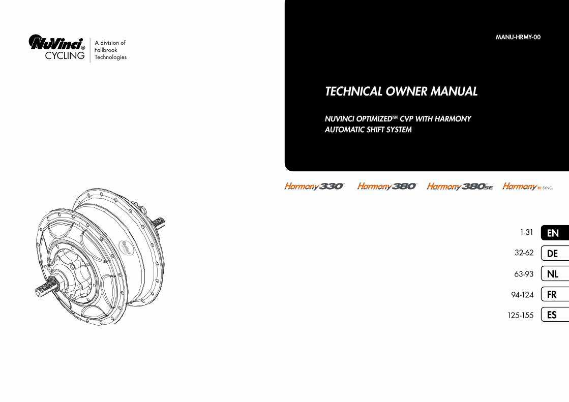
6.3 Installing the Input Speed Ring
1. Belt compatible Harmony systems come with an Input speed ring (A) that must be secured onto the assembled sprocket snap Ring (B). The twelve magnets in the Input speed ring provide pedal cadence for the Harmony system.
2. After installing the sprocket (C), sprocket spacer (D, if required), and sprocket snap sing (B, see section 6.2), and prior to installing the Harmony Hub Interface (see section 6.6), install the input speed ring (A) over the assembled sprocket snap ring (B)
• Assemble with the magnets facing the sprocket, as shown.
• Align the “tooth” on the Input speed ring with the opening of the sprocket snap ring (E), as shown.
• Snap and secure the Input speed ring over the assembled sprocket snap ring.
B
C
D
A
E
Chain-only Harmony systems do not utilize the input speed ring, as they sense input speed directly from
the steel chain sprocket. If you are unsure of which system the bicycle came installed with, see section 8.5.
A
!
HARMONY ASSEMBLY OF COMPONENTS
14
EN
TECHNICAL OWNER MANUAL
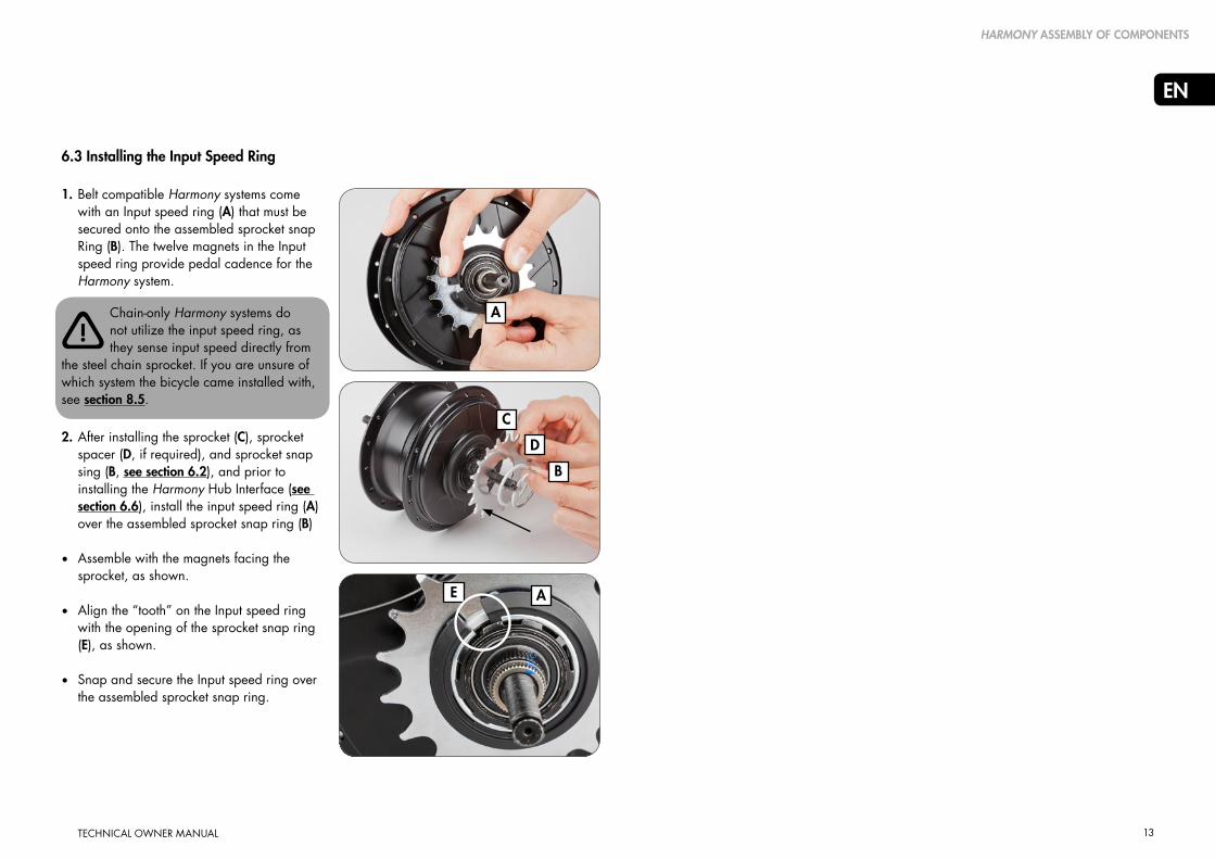
6.4 Installing the Output Speed Ring
Belt Compatible Harmony systems require an output speed ring (A) that must be secured over the CVP, flush with the CVP cover (B).Six magnets in the output speed ring provide bicycle speed for the Harmony system.
1. Prior to installing the Harmony Hub interface, assemble the output speed ring over the right hand side of the CVP, and secure with the included fastener (C).
• The fastener may need to be unthreaded to allow initial fitment.
• Assemble with the larger diameter flange outboard and the fastener inboard, flush with the CVP cover as shown.
• Locate the fastener portion between spoke holes and spokes, as shown.
2. Torque the fastener to 1.0 Nm (9 in-lbs).
B
C
AChain-only Harmony systems do not utilize the output speed ring, but rather utilize a hub encoder. If you
are unsure of which system the bicycle came installed with, see section 8.5.
!
HARMONY ASSEMBLY OF COMPONENTS

15
EN
TECHNICAL OWNER MANUAL
6.5 Installing the Hub Encoder (Older Harmony Systems)
Older “chain only” Harmony systems require a color-matched hub encoder (A) that must be secured over the CVP cover. Six magnets in the hub encoder provide bicycle speed for the Harmony system.
Belt-compatible Harmony systems do not utilize the output speed encoder, but rather utilize an output speed
ring. If you are unsure of which system the bicycle came installed with, see section 8.5.
1. Prior to installing the sprocket, align the hub encoder over the right hand side of the CVP.
• Assemble with the hub encoder magnets facing the CVP.
• Align the key on the CVP r.h. shield (B) with the keyway (C) on the hub encoder, as shown.
2. Install the hub encoder by starting at the key location and pressing the hub encoder onto the r.h. shield.
• “Walk” the snap-fit around to the opposite side of the key location with continuous pressure.
• The hub encoder should be tight and secure, flush to the CVP (D), as shown.
HARMONY ASSEMBLY OF COMPONENTS
D
C
B
A
!

16
EN
TECHNICAL OWNER MANUAL
B
D
E
6.6 HarmonyTM Hub Interface Compatibility & Orientation1. Ensure you have the correct Harmony Hub
Interface for your NuVinci Optimized CVP.
• N330/N330f CVPs have a yellow dot (A), and are compatible only with HHI3 Hub Interfaces (B, for Harmony systems).
• N360 and N380/N380SE CVPs have a black colored shift driver (C), and are compatible only with HHI8 and H|Sync Hub Interfaces (D, for Harmony 380 and Harmony H|Sync systems).
2. Use the uninstalled Harmony Hub Interface (E) to determine the desired orientation
• Orientation should be forward, parallel to the chain stay with the Harmony main connector facing forward.
• Move the Harmony Hub Interface along the dropout to ensure clearance at different axle positions.
3. With the Harmony Hub Interface oriented correctly inside the right dropout, the installation angle (F) is the indicated angle of the dropout (20 degrees in this example).
• Use the markings on the Harmony Hub Interface to determine your approximate installation angle.
C
A
6.6 Harmony Hub Interface Compatibility & Orientation
N330/N330f and N360/N380/N380SE series CVPs have different shift driver configurations, and are
compatible only with the appropriate Harmony Hub Interface. Do not attempt to fit incorrect Harmony Hub Interfaces, as damage will occur.
0° 0°
F
20°
compatible
compatible
incom
patib
le
D
incompatible
!
Harmony Hub Interface 3
Harmony Hub Interface 8 Harmony Hub Interface Sync
N330/N330f CVP
N360/N380/N380SE CVP
HARMONY ASSEMBLY OF COMPONENTS

17
EN
TECHNICAL OWNER MANUAL
6.7 Installing the Harmony Hub Interface
1. Remove the anti-shift retainer, if installed (reference section 6.2)
N330/N330f and N360/N380/N380SE series CVPs have different shift driver configurations, and
are compatible only with the appropriate Harmony Hub Interface. Reference section 6.6.
Shift driver position does not matter during assembly of Harmony products; the calibration process will
automatically determine shift driver position.
2. Suspend the Harmony Hub Interface over the right hand axle, and align the axle flats (A) with the installation angle determined in section 6.6.
• Alternatively, a no-turn washer (B) can be installed over the Harmony Hub Interface to align the installation angle.
3. When the installation angle is aligned seat the Harmony Hub Interface fully onto the shift driver and the spline nut until it is flush with the spline nut, as shown.
4. Thread the r.h. nut (C), serrations facing outward, onto the axle and tighten to 10-15 Nm (7-11 ft-lbs).
5. Install the rear wheel per section 5.2.
A
B
C
C
!
!
HARMONY ASSEMBLY OF COMPONENTS

18
EN
TECHNICAL OWNER MANUAL
6.8 Installing the Harmony H8 Controller
1. Install right brake lever according to the manufacturer’s instruction.
2. Slide the H8 controller (A) onto the handlebar.
3. Install the right hand grip (B) onto the handlebar according to the manufacturer’s instructions
4. Position the contoller such that the display (C) is visible to the rider and the cable will be unobstructed
• Tighten the clamp bolt to 2.0-2.5 Nm (18-22 in-lbs).
Never use lubricants or solvents to install handlebar grips.
Make sure that the controller and the brake lever function properly and are unobstructed (re-adjust if necessary).
Never ride without the handlebar grips. The turning grip of the Shifter could become loose. This can result
in a severe injury.
HARMONY ASSEMBLY OF COMPONENTS
6.9 Installing the Harmony H3 Controller
1. The H3 controller mounts to a rubber base that wraps around a standard handlebar, adjacent to the grip.
2. Use the supplied rubber o-ring to secure the H3 controller, and position such that the display is visible to the rider and the cable will be unobstructed.
• The H3 controller can be mounted to either right or left sides of the handlebar
C
A
B
!
!
!

19
EN
TECHNICAL OWNER MANUAL
6.10 Harmony Electrical Connections
An overview of Harmony 330 and Harmony 380/380SE electrical connections is provided below:
HARMONY ASSEMBLY OF COMPONENTS
An overview of Harmony H|Syncelectrical connections is provided below:
Y-Harness – Harmony Hub Interface to buttom bracket (bb) area
Power Harness – Battery / eBike system power to bb area
Rider Controller Cable – Handlebar to BB area
Connection to eBike power (OEM to provide)
Harmony connections (provided)
18-44V
H|Sync Harness – Connects directly to eBike system for power and CAN communication
H|Sync connections (provided)
20
EN
TECHNICAL OWNER MANUAL
7. Harmony service instructions
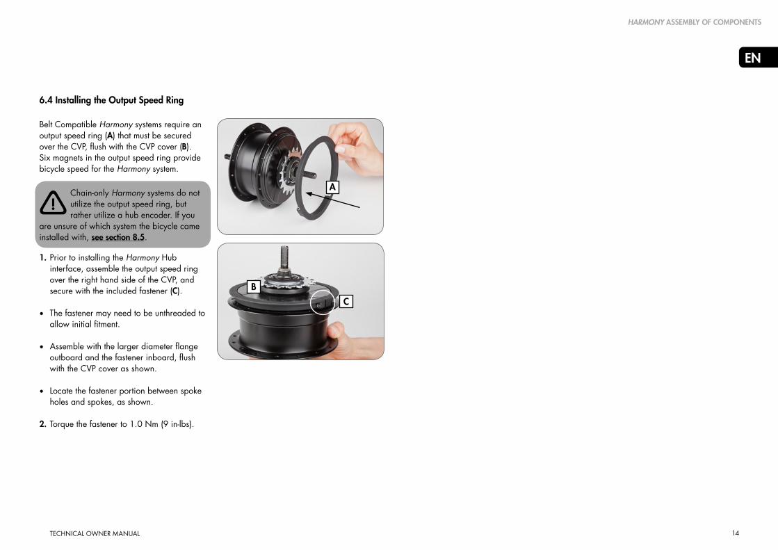
7.1 Servicing or Replacing Freewheel
1. Remove the rear wheel per section 5.1.
2. Remove the Harmony Hub Interface and Harmony input speed ring per reversing section 6.7 and section 6.3.
3. Reference the exploded view in section
8.3. Remove the sprocket snap ring (12), sprocket spacer (13, if installed), and sprocket (14).
4. Remove the snap sing (15) on the shift driver, and remove the freewheel assembly (16).
5. If servicing or replacing, use a medium-weight oil or very lightweight water-resistant grease and check pawl and spring function.
6. Remove the interior snap ring (17), needle bearing (18), and r.h. shield (19) if these components are being replaced.
7. Install the serviced / new freewheel components according to the exploded view in section 8.3.
8. Install the sprocket and Harmony components per step 2. and step 3. above.
9. Install the rear wheel per section 5.2.
HARMONY SERVICE INSTRUCTIONS
1918171615
15
18
19
15
16
21
EN
TECHNICAL OWNER MANUAL
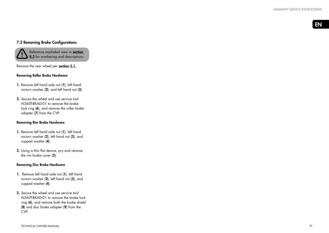
7.2 Removing Brake Configurations
Reference exploded view in section 8.3 for numbering and descriptions.
Remove the rear wheel per section 5.1.
Removing Roller Brake Hardware
1. Remove left hand axle nut (1), left hand no-turn washer (2), and left hand nut (3).
2. Secure the wheel and use service tool N360T-BKAD-01 to remove the brake lock ring (6), and remove the roller brake adapter (7) from the CVP.
Removing Rim Brake Hardware
1. Remove left hand axle nut (1), left hand no-turn washer (2), left hand nut (3), and cupped washer (4).
2. Using a thin flat device, pry and remove the rim brake cover (5).
Removing Disc Brake Hardware
1. Remove left hand axle nut (1), left hand no-turn washer (2), left hand nut (3), and cupped washer (4).
2. Secure the wheel and use service tool
N360T-BKAD-01 to remove the brake lock ring (6), and remove both the brake shield (8) and disc brake adapter (9) from the CVP.
HARMONY SERVICE INSTRUCTIONS
!
22
EN
TECHNICAL OWNER MANUAL
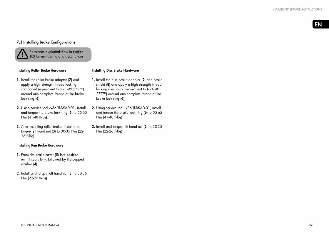
7.3 Installing Brake Configurations
Reference exploded view in section 8.3 for numbering and descriptions.
Installing Roller Brake Hardware
1. Install the roller brake adapter (7) and apply a high strength thread locking compound (equivalent to Loctite® 277™) around one complete thread of the brake lock ring (6).
2. Using service tool N360T-BKAD-01, install and torque the brake lock ring (6) to 55-65 Nm (41-48 ft-lbs).
3. After installing roller brake, install and torque left hand nut (3) to 30-35 Nm (22-26 ft-lbs).
Installing Rim Brake Hardware
1. Press rim brake cover (5) into position until if seats fully, followed by the cupped washer (4).
2. Install and torque left hand nut (3) to 30-35 Nm (22-26 ft-lbs).
HARMONY SERVICE INSTRUCTIONS
Installing Disc Brake Hardware
1. Install the disc brake adapter (9) and brake shield (8) and apply a high strength thread locking compound (equivalent to Loctite® 277™) around one complete thread of the brake lock ring (6).
2. Using service tool N360T-BKAD-01, install
and torque the brake lock ring (6) to 55-65 Nm (41-48 ft-lbs).
3. Install and torque left hand nut (3) to 30-35 Nm (22-26 ft-lbs).
!

23
EN
TECHNICAL OWNER MANUAL
8. Harmony technical data
HARMONY TECHNICAL DATA
8.1 CVP Specifications
*Harmony Hub Interfaces MY12-15 are chain compatible only
**This data refers to all Harmony Hub Interfaces MY12-15 which are chain compatible only
Hub N330/N330f
Hub colors Silver or black
Speed ratio Infinitely variable within ratio range
Ratio range 330% nominal, 0.5 underdrive to 1.65 overdrive
Controller H3
Other compatible controller –
Shifting Variable twist grip, ¾ turn
Hub Interface HHI3
Other compatible HI‘s –
Spoke configurations 32 or 36 hole
Brake configurations Disc, rim, or roller
CVP weight 2450 grams
Drop-out width 135mm, horizontal or vertical
Axle length 183mm
Axle threads M10 x 1
Chainline 49.0 ± 0.5mm
Beltline (Gates) 45.5 ± 0.5 mm
Beltline (Conti-Tech) 46.2 ± 0.5 mm
Sprocket sizes 16-22 tooth (chain)
20-28 tooth (belt)
Sprocket type Standard 9-spline, flat on one side
Sprocket ratio definition Front sprocket teeth / Rear sprocket teeth
Sprocket ratio minimum (Pedal bikes) 1.8 (Table in section 8.2)
Sprocket ratio minimum (Front motor e-Bikes) 1.8 (Table in section 8.2)
Sprocket ratio minimum (Mid motor e-Bikes) 2.1 (Table in section 8.2)
Spoke flange diameter 125.0 mm
Center to left spoke flange 26.0 mm
Center to right spoke flange 26.0 mm
Harmony 330
Hub N380/N380SE
Hub colors Silver or black
Speed ratio Infinitely variable within ratio range
Ratio range 380% nominal, 0.5 underdrive to 1.9 overdrive
Controller H8
Other compatible controller H|Sync
Shifting Variable twist grip, ¾ turn
Hub Interface HHI8
Other compatible HI‘s H|SYNC, (Harmony Hub Interfaces MY12-15)*
Spoke configurations 32 or 36 hole
Brake configurations Disc, rim, or roller
CVP weight 2450 grams
Drop-out width 135mm, horizontal or vertical
Axle length 183mm
Axle threads M10 x 1
Chainline 49.0 ± 0.5mm
Beltline (Gates) 45.5 ± 0.5 mm
Beltline (Conti-Tech) 46.2 ± 0.5 mm
Sprocket sizes 16-20 tooth (chain)
16-22 tooth (chain)**
20-28 tooth (belt)
Sprocket type Standard 9-spline, flat on one side
Sprocket ratio definition Front sprocket teeth / Rear sprocket teeth
Sprocket ratio minimum (Pedal bikes) 1.8 (Table in section 8.2)
Sprocket ratio minimum (Front motor e-Bikes) 1.8 (Table in section 8.2)
Sprocket ratio minimum (Mid motor e-Bikes) 2.1 (Table in section 8.2)
Spoke flange diameter 125.0 mm
Center to left spoke flange 26.0 mm
Center to right spoke flange 26.0 mm
Harmony 380/380SE

24
EN
HARMONY TECHNICAL DATA
8.2 Approved Gearing
- 2.1 minimum sprocket ratio for mid-motor eBikes rated at 250W or less
- 1.8 minimum sprocket ratio for all pedal bicycles and front motor eBikes
- 0.84 minimum sprocket ratio for Bosch GEN2 eBikes rated at 250W or less
- 2.0 minimum sprocket ratio for mid-motor eBikes rated at 350W or less
- 1.8 minimum sprocket ratio for all pedal bicycles and front motor eBikes
- 0.80 minimum sprocket ratio for Bosch GEN2 eBikes rated at 350W or less
58 & higher
56
54
52
50
48
46
44
42
40
39
38
36
34
33
32
30
28
27 & lower
58 & higher
56
54
52
50
48
46
44
42
40
39
38
36
34
33
32
30
28
27 & lower
N330 CVP Approved Gearing (Nfinity 330, Nfinity 330f & Harmony 330 Group Sets) N380 CVP Approved Gearing (Nfinity 380, Nfinity 380SE, Harmony 380, Harmony 380/380SE and Harmony HISync Group Sets)
Stan
dard
Fro
nt c
hain
rin
g /
spro
cket
Stan
dard
Fro
nt c
hain
rin
g /
spro
cket
24 & higher
23
22
21
20
19
18
17
16
15
14
13 & lower
24 & higher
23
22
21
20
19
18
17
16
15
14
13 & lower
Bosc
h G
EN2
front
Spr
ocke
t
Bosc
h G
EN2
front
Spr
ocke
t
16 17 18 19 20 21 22 23 24 26 28 16 17 18 19 20 21 22 23 24 26 28
Approved for any bicycle (including mid-motor eBikes rated at 250W or less) Approved for any bicycle (including mid-motor eBikes rated at 350W or less)
N330 CVP (Nfinity 330, Nfinity 330f & Harmony 330 Group sets) N380 CVP (Nfinity 380, Nfinity 380SE, Harmony 380/380SE and Harmony HISync Group sets)
Sprocket Ratio = Front chain ring teeth / Rear sprocket teeth Sprocket Ratio = Front chain ring teeth / Rear sprocket teeth
Not approved for any bicycle Not approved for any bicycle
Nfinity 330, Nfinity 330f
and Harmony 330 systems
are paired with the N330
CVP and are compatible with mid-motor
eBike systems rated at 250W or less,
with approved gearing as shown on the
associated N330 table on this page.
Nfinity 380, Nfinity 380SE,
Harmony 380/380SE and
Harmony HISync systems are
paired with the N380 CVP and are compatible
with mid-motor eBike systems rated at 350W
or less, with approved gearing as shown on
the associated N380 table on this page.
! !Approved for pedal bicycles and front hub motor eBikes (not approved for mid-motor eBikes) Approved for pedal bicycles and front hub motor eBikes (not approved for mid-motor eBikes)
3,6 3,4 3,2 3,1 2,9 2,8 2,6 2,5 2,4 2,2 2,1
3,5 3,3 3,1 2,9 2,8 2,7 2,5 2,4 2,3 2,2 2,0
3,4 3,2 3,0 2,8 2,7 2,6 2,5 2,3 2,3 2,1 1,9
3,3 3,1 2,9 2,7 2,6 2,5 2,4 2,3 2,2 2,0 1,9
3,1 2,9 2,8 2,6 2,5 2,4 2,3 2,2 2,1 1,9 1,8
3,0 2,8 2,7 2,5 2,4 2,3 2,2 2,1 2,0 1,8 1,7
2,9 2,7 2,6 2,4 2,3 2,2 2,1 2,0 1,9 1,8 1,6
2,8 2,6 2,4 2,3 2,2 2,1 2,0 1,9 1,8 1,7 1,6
2,6 2,5 2,3 2,2 2,1 2,0 1,9 1,8 1,8 1,6 1,5
2,5 2,4 2,2 2,1 2,0 1,9 1,8 1,7 1,7 1,5 1,4
2,4 2,3 2,2 2,1 2,0 1,9 1,8 1,7 1,6 1,5 1,4
2,4 2,2 2,1 2,0 1,9 1,8 1,7 1,7 1,6 1,5 1,4
2,3 2,1 2,0 1,9 1,8 1,7 1,6 1,6 1,5 1,4 1,3
2,1 2,0 1,9 1,8 1,7 1,6 1,5 1,5 1,4 1,3 1,2
2,1 1,9 1,8 1,7 1,7 1,6 1,5 1,4 1,4 1,3 1,2
2,0 1,9 1,8 1,7 1,6 1,5 1,5 1,4 1,3 1,2 1,1
1,9 1,8 1,7 1,6 1,5 1,4 1,4 1,3 1,3 1,2 1,1
1,8 1,6 1,6 1,5 1,4 1,3 1,3 1,2 1,2 1,1 1,0
1,7 1,6 1,5 1,4 1,4 1,3 1,2 1,2 1,1 1,0 1,0
1,50 1,41 1,33 1,26 1,20 1,14 1,09 1,04 1,00 0,92 0,86
1,44 1,35 1,28 1,21 1,15 1,10 1,05 1,00 0,96 0,88 0,82
1,38 1,29 1,22 1,16 1,10 1,05 1,00 0,96 0,92 0,85 0,79
1,31 1,24 1,17 1,11 1,05 1,00 0,95 0,91 0,88 0,81 0,75
1,25 1,18 1,11 1,05 1,00 0,95 0,91 0,87 0,83 0,77 0,71
1,19 1,12 1,06 1,00 0,95 0,90 0,86 0,83 0,79 0,73 0,68
1,13 1,06 1,00 0,95 0,90 0,86 0,82 0,78 0,75 0,69 0,64
1,06 1,00 0,94 0,89 0,85 0,81 0,77 0,74 0,71 0,65 0,61
1,00 0,94 0,89 0,84 0,80 0,76 0,73 0,70 0,67 0,62 0,57
0,94 0,88 0,83 0,79 0,75 0,71 0,68 0,65 0,63 0,58 0,54
0,88 0,82 0,78 0,74 0,70 0,67 0,64 0,61 0,58 0,54 0,50
0,81 0,76 0,72 0,68 0,65 0,62 0,59 0,57 0,54 0,50 0,46

25
EN
TECHNICAL OWNER MANUAL
8.3 Exploded View
HARMONY TECHNICAL DATA
18 16 14 12 10
19 17 15 13 11 2Rim brake configuration
Roller brake configuration
Disc brake configuration
Axle nut
No-turn washer
Left hand nut
Cupped washer
Rim brake cover
Brake lock ring
Roller brake adapter
Brake shield
Disc brake adapter
R.h.nut
Hub Interface
Sprocket snap ring
Sprocket spacer
Sprocket
Snap ring (freewheel)
Freewheel assy
Snap ring (interior)
Needle bearing
R.h. shield
A
B
C
1
2
3
4
5
6
7
8
9
10
11
12
13
14
15
16
17
18
19
7
9
48
6
4 5
1
2
3
A
B
C
(Optional – to be used with 2.3 mm thick sprockets)
Not supplied
Left (non-drive) side Right (drive) side
1

26
EN
TECHNICAL OWNER MANUAL
8.4 CVP & Harmony Shifter Dimensions
HARMONY TECHNICAL DATA
H3 controller H8 controller
CVP with Harmony Hub Interface CVP with Harmony Hub Interface Harmony Hub Interface
12532 AND 36 SPOKECONFIGURATIONS
AVAILABLE
2.9SPOKEHOLE
SCALE 0.500
SCALE 0.500
183 AXLE WIDTH
135 DROPOUT WIDTH
VERSIONDISC BRAKE
ISO 6 BOLT16.0
41
73
67.5CENTERLINE
49.0CHAINLINE
26.026.0
MULTI-GEAR(2.3MM OR 3/32")CHAINS ANDSPROCKETS ONLY

27
EN
TECHNICAL OWNER MANUAL
HARMONY TECHNICAL DATA
8.5 “Chain Only” and “Belt Compatible” Harmony Systems
1. How to identify “chain only” Harmony systems
• Produced from 2011 - 2015
• “Chain Only” Harmony systems include a hub encoder (A) that mounts on the face of the CVP cover, and is color matched to the CVP (silver or black)
• “Chain only” Harmony systems are compatible with 16-20T steel chain sprockets only A
B
C
A
B
C
2. How to identify “belt compatible” Harmony systems
• Produced from 2015 - current
• “Belt compatible” Harmony systems include an output speed ring (B) that mounts over the CVP Cover, always in black
• “Belt compatible” Harmony systems also include an Input speed ring (C) that mounts over the sprocket snap ring, always in black
• “Belt compatible” Harmony systems are compatible with 16-28T sprockets for chains or belts

28
EN
TECHNICAL OWNER MANUAL
INTELLECTUAL PROPERTY NOTICE
9. Intellectual property notice
The NuVinci Optimized N360, Harmony & Harmony H|Sync control units
Intellectual Property Notice
By purchasing and/or using these NuVinci Optimized components and/or the bicycle incorporating them, you agree to the following terms and conditions. If you do not want to be bound by these terms and conditions, you must return the NuVinci Optimized
components to your vendor within three (3) days for a full refund. The NuVinci Optimized
components sold herewith are to be used only in the rear wheel of a bicycle for usual and customary rear hub purposes and in accordance with the accompanying instructions. You agree not to use the NuVinci Optimized components for any other use or purpose, including without limitation reverse engineering or reproduction. Any unauthorized use of the NuVinci Optimized
components is not recommended, will void any applicable warranties and, to the extent such use leads to any improvements to or inventions from those components, and as allowed under applicable law, Fallbrook Technologies Inc. and its licensees shall have a royalty free, worldwide, perpetual, non-exclusive license to all rights in any such inventions or improvements.
The NuVinci Optimized components sold herewith, including, but not limited to the rearHub, controller and gear shifter, are protected by U.S. patents 7,871,353; 7,885,747; 7,959,533; 8,321,097, 8,376,903; 8,398,518; 8,506,452; 8,626,409; and European Patents EP2171312; EP2234869;Dansk Patent No. 1954959; Spanish Patent ES2424652; as well as other patents. Other U.S. and foreign patent applications are pending for Fallbrook Technologies Inc. and its subsidiary Fallbrook Intellectual Property Co. LLC.
The Harmony and H|Sync products also include software, firmware or other digital information (collectively the “Software”) that may be embedded or is available from Fallbrook Technologies or its authorized representatives for use with the products.
The Software is protected by copyright laws in each jurisdiction or country and any unauthorized reproduction, display, use, publication or adaptation is strictly prohibited.
Fallbrook, NuVinci, N360, Harmony, Harmony H|Sync and their stylized logos and associated elements are trademarks or registered trademarks of Fallbrook Technologies Inc.Bosch and Intuvia are trademarks of Robert Bosch GmbH.
All rights reserved. © 2015

29
EN
TECHNICAL OWNER MANUAL
10. Warranty
WARRANTY
THE FOLLOWING WARRANTY IS A VOLUNTARY TWO-YEAR LIMITED WARRANTY OFFERED BY FALLBROOK TECHNOLOGIES INC. (“FALLBROOK”). IT IS OFFERED TO ALL PURCHASERS OF THE NUVINCI OPTIMIZED, N330, N330f N360, N380, N380SE, C3, C8, C8S, H3, H8, NFINITY 330, NFINITY 330f, NFINITY 380, NFINITY N380SE, HARMONY 330, HARMONY 380, HARMONY 380SE, HARMONY H|SYNC, NFINITY HI, HHI3, HHI8, HHISYNC (COLLECTIVELY, THE “FALLBROOK PRODUCTS”).
UNDER THE LAWS IN CERTAIN COUNTRIES (e.g., GERMANY, NETHERLANDS), A PURCHASER IS ENTITLED TO STATUTORY RIGHTS WITH RESPECT TO PRODUCTS THAT ARE DEFECTIVE OR DO NOT CONFORM WITH THE CONTRACT OF SALE. THESE RIGHTS ALLOW A PURCHASER TO DEMAND, FREE OF CHARGE, REPAIR, REPLACEMENT, OR UNDER CERTAIN CONDITIONS, DISCOUNT OR REFUND BY THE SELLER OF SUCH PRODUCTS. THIS VOLUNTARY WARRANTY DOES NOT AFFECT YOUR STATUTORY RIGHTS. IF YOU LIVE IN ONE OF THESE COUNTRIES, WHEN YOU PURCHASE FALLBROOK PRODUCTS, IN ADDITION TO YOUR STATUTORY RIGHTS, YOU ARE ALSO ENTITLED TO CLAIMS OUT OF FALLBROOK’S LIMITED WARRANTY DESCRIBED BELOW. THESE CLAIMS EXIST CONCURRENTLY WITH YOUR STATUTORY RIGHTS SO THAT, SHOULD YOUR FALLBROOK PRODUCT BE DEFECTIVE OR IF IT DOES NOT CONFORM WITH THE CONTRACT OF SALE, WHILE THE LIMITED WARRANTY IS IN PLACE, YOU CAN CHOOSE TO MAKE A CLAIM UNDER YOUR COUNTRY’S LAW OR FALLBROOK’S LIMITED WARRANTY.
What does this warranty cover?
Fallbrook Technologies Inc. (Fallbrook) warrants any Fallbrook product that is defective in materials or workmanship. This warranty only extends to the original purchaser and is not transferable. (Some states or countries do not allow restriction of warranty coverage to the original buyer, so this restriction may not apply to you). If you purchased your Fallbrook product as part of another product, this warranty in no way replaces or is an extension of the warranty of the manufacturer of that product, which warranty is the sole responsibility of that product’s manufacturer.
How long does this warranty last?
The warranty period lasts two years from the date of original purchase.
What will Fallbrook do?
Fallbrook will, at Fallbrook’s sole option, repair, replace or refund the cost of the defective unit.
What does this warranty not cover?
• This warranty does not apply to any of the following:
• Normal wear and tear to components subject to wear, such as, for example, rubber seals and rings, jockey wheels on chain tensioner (if applicable), twist grip rubber, and shifter cables.
• Damage to parts not manufactured by Fallbrook or its related entities (such as dropouts and chains).
• Labor required to remove, re-fit or re-adjust the product within the bicycle assembly
• A product used in any installation other than a single rider bicycle. Tandems are not covered.
• A product that has been incorrectly installed and/or not adjusted according to the Nfinity 330, Nfinity 330f, Nfinity 380, Nfinity 380SE, Harmony 330, Harmony 380, Harmony 380SE or Harmony H|Sync technical installation manual, which can be found at http://www.nuvincicycling.com/en/service/downloads.html
• A product that has been disassembled into its components beyond the scope of service documentation (Technical Owner Manuals for NuVinci Optimized CVP with Harmony or Nfinity shift system).

30
EN
TECHNICAL OWNER MANUAL
WARRANTY
• A product that has been modified or where the serial number or date code has been altered, defaced or removed.
• A product other than the N330f that is used for commercial purposes without written pre-authorization from Fallbrook. Only N330f may be used for reasonable commercial purposes and this warranty will be limited to one (1) year for such reasonable commercial use.
• Damage to the product: - determined by Fallbrook to be caused by crash, impact, or abuse of the product; - resulting from use of the product in what Fallbrook, in its sole discretion, considers extreme applications such as, but not limited to, downhill, freeride, “North Shore” style, and BMX; - resulting from powering of the product with electric motors rated over 250 Watts for N330/N330f/N360 and 350 Watts for N380/N380SE, or any powering of the product with internal combustion engines; - resulting from running of the product with electric motors at continuous torque over 80Nm and peak torque over 90Nm;
- resulting from use of the product with total weight (rider, cargo and bike) of over 200kg; - resulting from use of the product outside the defined cog ratio limits at 1.8 to 1 on standard bikes and 2.1 to 1 (N330/N330f) or 2.0 to 1 (N380/N380SE) on eBikes; - resulting from use of the product at voltages of over 50V; - caused by the use of parts that are not compatible, suitable and/or authorized by Fallbrook for use with the product; or - occurring during shipment of the product.
How to get warranty service?
Claims under this warranty must be made through the dealer where the vehicle or the Fallbrook component was purchased, or through an authorized dealer of NuVinci Optimized components. Please return the Fallbrook component to the dealer together with the original, dated invoice or receipt. The dealer will contact Fallbrook customer service to handle your warranty claim.Dealers requesting a warranty claim should contact Fallbrook customer service to obtain a Warranty Return Authorization. The dealer will then need to return the product to Fallbrook together with satisfactory proof of the date of purchase.

31
EN
TECHNICAL OWNER MANUAL
WARRANTY
Limitations of warranty
THIS LIMITED WARRANTY IS THE SOLE AND EXCLUSIVE WARRANTY MADE BY FALLBROOK WITH RESPECTTO THE PRODUCT, AND IS GIVEN IN LIEU OF ANY OTHER WARRANTY. TO THE EXTENT ALLOWEDBY APPLICABLE LAW, ANY AND ALL EXPRESS OR IMPLIED WARRANTIES NOT SET FORTH HEREIN ARE WAIVED AND DISCLAIMED, INCLUDING ANY IMPLIED WARRANTY OF MERCHANTABILITY OR FITNESS FOR A PARTICULAR USE. FALLBROOK LIABILITY UNDER THIS LIMITED WARRANTY IS LIMITED SOLELY TO THOSELIABILITIES SET FORTH ABOVE. IN THE EVENT THAT ANY PROVISION OF THIS LIMITED WARRANTY SHOULD BE OR BECOME INVALID OR UNENFORCEABLE UNDER APPLICABLE LAW, THE REMAINING TERMS AND CONDITIONS HEREOF SHALL REMAIN IN FULL FORCE AND EFFECT AND SUCH INVALID OR UNENFORCEABLE PROVISION SHALL BE CONSTRUED IN SUCH A MANNER AS TO BE VALID AND ENFORCEABLE.
Fallbrook reserves the right to revise this limited warranty without notice.
NuVinci CYCLINGSupport and Service – USA
Fallbrook Technologies Inc.Cedar Park, Texas 78613 USA
USA toll free: 1-888-NuVinci (688-4624)
Tel: +1 (512) 279-6200 Fax: +1 (512) 267-0159
NuVinci CYCLINGSupport and Service – Europe
Fallbrook Technologies InternationalPopovstraat 128013 RK Zwolle, The Netherlands
Germany and Austria+49 2289 2939 [email protected]
Switzerland+41 43 508 55 [email protected]
Europe General Support+31 38 7200 [email protected]

32
DE
TECHNISCHES BEDIENUNGSHANDBUCH
TECHNISCHES BEDIENUNGSHANDBUCH
NUVINCI OPTIMIZEDTM CVP MITHARMONY AUTOMATIK-SCHALTSYSTEM
MANU-HRMY-00
EN
DE32-62
1-31
63-93
94-124
NL
FR
125-155 ES

33
DE
TECHNISCHES BEDIENUNGSHANDBUCH
Inhaltsverzeichnis
1. NuVinci Cycling-Produkte 34
1.2 Das NuVinci Optimized CVP 34
2. Harmony 330 Bedienung & Handhabung 35
2.1 Harmony 330 System 35
2.2 Das System Harmony 330 kalibrieren 35
2.3 Upgrade des Harmony 330 Systems 35
3. Harmony 380 Bedienung & Handhabung 36
3.1 Harmony 380/380SE System 36
3.2 Das Harmony 380/380SE System kalibrieren 36
4. Harmony H|SYNC Bedienung & Handhabung 37
4.1 Harmony H|Sync System 37
4.2 Das Harmony H|Sync System kalibrieren
- Allgemein 37
4.3 Das Harmony H|Sync System kalibieren
- Bosch Intuvia 38
5. Harmony - Allgemeine Handhabung 39
5.1 Das Hinterrad ausbauen 39
5.2 Das Hinterrad einbbauen 40
5.3 Reingung & Schmierung 41
6. Harmony - Montage von Einzelteilen 42
6.1 Laufradbau 42
6.2 Das Ritzel montieren 43
6.3 Den Eingabe-Geschwindigkeits-Ring montieren 44
6.4 Den Abgabe-Geschwindigkeits-Ring montieren 45
6.5 Den Naben-Kodierer montieren 46
6.6 Kompatibilität der Harmony-Nabenverbindung &
Ausrichtung 47
6.7 Die Harmony-Nabenverbindung montieren 48
6.8 Den Harmony H8 Controller montieren 49
6.9 Den Controller Harmony H3 montieren 49
6.10 Harmony Elektrische Verbindungen 50
7. Harmony Wartungsanweisungen 51
7.1 Den Freilauf warten oder reparieren 51
7.2 Bremsen-Konfiguration entfernen 52
7.3 Bremsen Konfigurationen montieren 53
8. Harmony Technische Daten 54
8.1 CVP-Spezifikationen 54
8.2 Zugelassene Getriebeübersetzung 55
8.3 Explosionszeichnung 56
8.4 CVP & Harmony Schaltstück-Abmessungen 57
8.5 "Nur Kette" und "Riemen-kompatibel"
Harmony-Systeme 58
9. Hinweis auf geistiges Eigentum 59
10. Garantie 60
Support und Service in Europa 62
Niederlassung Nordamerika 62
34
DE
TECHNISCHES BEDIENUNGSHANDBUCH
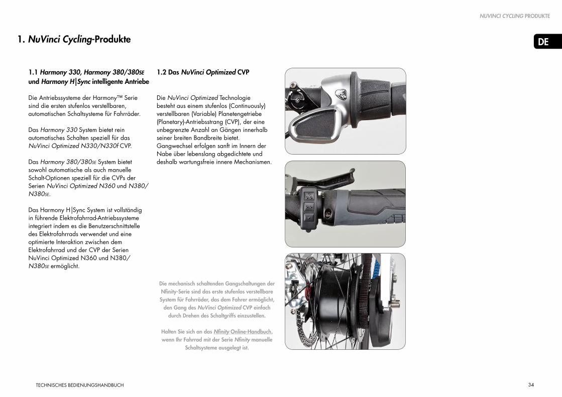
1.1 Harmony 330, Harmony 380/380SE und Harmony H|Sync intelligente Antriebe
Die Antriebssysteme der Harmony™ Serie sind die ersten stufenlos verstellbaren, automatischen Schaltsysteme für Fahrräder.
Das Harmony 330 System bietet rein automatisches Schalten speziell für das NuVinci Optimized N330/N330f CVP.
Das Harmony 380/380SE System bietet sowohl automatische als auch manuelle Schalt-Optionen speziell für die CVPs der Serien NuVinci Optimized N360 und N380/N380SE.
Das Harmony H|Sync System ist vollständig in führende Elektrofahrrad-Antriebssysteme integriert indem es die Benutzerschnittstelle des Elektrofahrrads verwendet und eine optimierte Interaktion zwischen dem Elektrofahrrad und der CVP der Serien NuVinci Optimized N360 und N380/N380SE ermöglicht.
1. NuVinci Cycling-Produkte
1.2 Das NuVinci Optimized CVP
Die NuVinci Optimized Technologie besteht aus einem stufenlos (Continuously) verstellbaren (Variable) Planetengetriebe (Planetary)-Antriebsstrang (CVP), der eine unbegrenzte Anzahl an Gängen innerhalb seiner breiten Bandbreite bietet. Gangwechsel erfolgen sanft im Innern der Nabe über lebenslang abgedichtete und deshalb wartungsfreie innere Mechanismen.
NUVINCI CYCLING PRODUKTE
Die mechanisch schaltenden Gangschaltungen der Nfinity-Serie sind das erste stufenlos verstellbare System für Fahrräder, das dem Fahrer ermöglicht,
den Gang des NuVinci Optimized CVP einfach durch Drehen des Schaltgriffs einzustellen.
Halten Sie sich an das Nfinity Online-Handbuch, wenn Ihr Fahrrad mit der Serie Nfinity manuelle
Schaltsysteme ausgelegt ist.

35
DE
TECHNISCHES BEDIENUNGSHANDBUCH
2. Harmony 330 Bedienung & Handhabung
2.1 Harmony 330 System
• Das System Harmony 330 ist nur mit dem CVP NuVinci Optimized N330/N330f kompatibel und ermöglicht dem Fahrer jederzeitiges automatisches Schalten.
• Das Harmony 330 System verwendet den Controller Harmony H3 (A), der automatisches Schalten auf Tastendruck möglich macht, um Ihre Trittfrequenz zu wählen. Die Einstellungen der Frequenz (normalerweise langsam, mittel oder schnell) sind entsprechend der Spezifikationen der Fahrrad- und Getriebeübersetzung des Elektrofahrradherstellers voreingestellt.
A
HARMONY 330 BEDIENUNG & HANDHABUNG
2.2 Das System Harmony 330 kalibrieren
Wenn das Harmony-System wieder montiert wurde oder der Systembetrieb unzuverlässig oder fehlerhaft ist, muss ihr System Harmony 330 eventuell kalibriert werden.
Um dies zu tun:
1. Schalten Sie das System ein.
2. Treten Sie die Pedale leicht über den gesamten Kalibrierungsvorgang hinweg (am Besten an einem Ständer, wenn das Hinterrad den Boden nicht berührt).
3. Drücken und halten Sie die oberen und unteren Tasten (B) am Controller Harmony H3 gleichzeitig gedrückt bis die hintere Nabe zu schalten beginnt (normalerweise 5 - 7 Sekunden) und lassen Sie dann die Tasten los.
4. Treten Sie weiter leicht in die Pedale während das System mehrmals vom "niedrigen" in einen "hohen" Gang schaltet und die Kalibrierung abschließt.
2.3 Upgrade des Harmony 330 Systems
Wenn der Fahrer eine Erweiterung vom Controller Harmony H3 zum Controller Harmony H8 wünscht, kann dies durch einfaches „Plug and Play“ erfolgen. Wenden Sie sich für weitere Einzelheiten an Ihren Händler oder NuVinci Cycling Kundendienst.
B
Das CVP NuVinci Optimized kann im Stillstand nicht über die gesamte Bandbreite der Gänge geschaltet
werden. Das Harmony-System wartet intelligenterweise auf Pedaltritte oder Radbewegung, wenn weite Gang-Bereiche im Stillstand geschaltet werden.
B
Obere & Untere Tasten
!
"Schnelle" Trittfrequenz
"Mittlere" Trittfrequenz
"Langsame" Trittfrequenz

36
DE
TECHNISCHES BEDIENUNGSHANDBUCH
3. Harmony 380/380SE Bedienung & Handhabung
3.1 Harmony 380/380SE System
• Das Harmony 380/380SE System ist mit den CVPs der Serien NuVinci Optimized N360 und N380 kompatibel (es ist allerdings nicht kompatibel mit dem CVP NuVinci Optimized N330).
• Das System Harmony 380/380SE verwendet den Controller Harmony H8, der sowohl manuelle wie auch automatische Schalt-Optionen bietet. Der Fahrer schaltet zwischen "Automatik" und "Manuell"-Modus um, indem er die "Modus"-Taste (A) auf dem Gehäuse des Controllers H8 drückt.
• Im Automatik-Modus passt Harmony 380/380SE den Gang automatisch an, um die bevorzugte Trittfrequenz des Fahrers beizubehalten. Der Fahrer kann die ideale Frequenz-Einstellung durch Drehen des Griffs wählen. Die blaue "1/min"- LED-Anzeige zeigt die eingestellte Trittfrequenz- (B).
• Im manuellen Modus kann der Fahrer mit der "Ride by Wire"-Technologie selbst schalten. Wie beim Seilschaltsystem ist das Bergauf-Fahren im Geländegang umso leichter, je steiler der orange "Hügel" auf der LED-Anzeige (C) ist.
3.2 Das Harmony 380/380SE System kalibrieren
Wenn das System Harmony wieder montiert wurde oder der Systembetrieb unzuverlässig oder falsch ist, muss ihr System Harmony 380/Harmony380SE eventuell kalibriert werden.
Um dies zu tun:
1. Schalten Sie das System ein.
2. Treten sie die Pedale leicht über den gesamten Kalibrierungsvorgang hinweg (am besten an einem Ständer, wenn das Hinterrad den Boden nicht berührt).
3. Drücken und halten Sie die "Modus"-Taste (A) am Controller Harmony H8 bis die hintere Nabe zu schalten beginnt (normalerweise 5 - 7 Sekunden) und lassen Sie dann die Taste los.
4. Treten Sie weiter leicht in die Pedale, während das System mehrmals vom "niedrigen" in einen "hohen" Gang. schaltet und die Kalibrierung abschließt.
HARMONY 380 BEDIENUNG & HANDHABUNG
Die NuVinci Optimized CVPs können im Stillstand nicht über die gesamte Bandbreite der Gänge
geschaltet werden. Das Harmony-System wird intelligenterweise auf Pedalentritte oder Räderbewegung warten, wenn weite Gang-Bereiche im Stillstand geschaltet werden.
"Modus"-Taste A
CManueller Modus
Easier ratio for climbing
BAutomatik-Modus
Schnellere Trittfrequenz- Einstellung
!
Langsamere Trittfrequenz-Einstellung
Faster ratio for speed

37
DE
TECHNISCHES BEDIENUNGSHANDBUCH
4.2 Das Harmony H|Sync System kalibrieren - Allgemein
Wenn das System Harmony wieder montiert wurde oder der Systembetrieb unzuverlässig oder fehlerhaft ist, muss ihr System Harmony H|Sync eventuell kalibriert werden.
Um dies zu tun:
1. Schalten Sie das System ein.
2. Treten sie die Pedale leicht über den gesamten Kalibrierungsvorgang hinweg (am Besten auf einem Ständer, wenn das Hinterrad den Boden nicht berührt).
3. Starten Sie die Kalibrierung Ihres E-Fahrrades Harmony H|Sync. - Wenn dies in den folgenden Abschnitten nicht beschrieben ist, wenden Sie sich an das Handbuch ihres Elektrofahrradsystems für Anweisungen zur Kalibrierung von Harmony H|Sync.
4. Treten Sie weiter leicht in die Pedale,
während das System mehrmals vom "niedrigen" in einen "hohen" Gang schaltet und die Kalibrierung abschließt.
4. Harmony H|SYNC Bedienung & Handhabung
4.1 Harmony H|Sync System
• Das Harmony H|Sync System ist mit den CVPs der Serien NuVinci Optimized N360 und N380 / N380SE kompatibel (es ist allerdings nicht kompatibel mit dem CVP NuVinci Optimized N330/N330f).
• Das Harmony H|Sync System ist in das
Steuerungssystem des E-Fahrrads integriert und bietet sowohl einen Automatik- als auch einen manuellen Schaltmodus.
• Im Automatik-Modus passt Harmony H|Sync den Gang automatisch an, um die bevorzugte Trittfrequenz des Fahrers beizubehalten. Der Fahrer kann seine ideale Trittfrequenz auf der Benutzeroberfläche des Elektrofahrrades wählen, wie im Handbuch des Elektrofahrradsystems dokumentiert.
• Wenn dies von Hersteller des Elektrofahrrades unterstützt wird, ermöglicht der manuelle Modus dem Fahrer, mit der "Ride by Wire"-Technologie selbst zu schalten. Der Fahrer kann seine ideale Trittfrequenz auf der Benutzeroberfläche des Elektrofahrrades wählen, wie im System-Handbuch des Elektrofahrrades dokumentiert.
HARMONY H|SYNC BEDIENUNG & HANDHABUNG
Die NuVinci Optimized CVPs können im Stillstand nicht über die gesamte Bandbreite der Gänge
geschaltet werden. Das Harmony-System wird intelligenterweise auf Pedalentritte oder Räderbewegung warten, wenn weite Gang-Bereiche im Stillstand geschaltet werden.
!

38
DE
TECHNISCHES BEDIENUNGSHANDBUCH
HARMONY H|SYNC BEDIENUNG & HANDHABUNG
A
4.3 Das Harmony H|Sync System kalibieren - Bosch Intuvia
Wenn das System Harmony wieder montiert wurde oder der Systembetrieb unzuverlässig oder fehlerhaft ist, muss ihr System Harmony H|Sync eventuell kalibriert werden.
Um dies am Bosch Intuvia - System zu tun:
1. Schalten Sie das Elektrofahrradsystem Bosch Intuvia ein, wenn alle Komponenten angeschlossen sind.
2. Aktivieren Sie den Bosch Intuvia "Konfigurations"-Modus, indem Sie gleichzeitig die [ RESET ]- und [ i ]-Taste gedrückt halten (A).
3. Sobald Sie im Konfigurationsmodus sind, drücken Sie die [ i ]-Taste, bis Sie "Gear calibration " auf der Intuvia-Anzeige sehen.
4. Beginnen Sie, schnell, aber fest in die Pedale zu treten, wobei sich das Hinterrad oberhalb des Bodens befinden muss.
5. Während Sie mit dem Treten fortfahren, drücken Sie die [ ]-Taste (B) einmal, um die Kalibrierung zu beginnen. Setzen Sie den Vorgang durch schnelles, aber leichtes Treten fort.
A
B
6. Nach dem Abschluss des Vorgangs erscheint die Anzeige "Success" auf dem Display.
7. Verlassen Sie den Bosch Intuvia "Konfigurations"-Modus, indem Sie die [ RESET ]-Taste gedrückt halten.

39
DE
TECHNISCHES BEDIENUNGSHANDBUCH
5. Harmony - Allgemeine Handhabung
5.1 Das Hinterrad ausbauen
Schalten Sie Ihr eBike aus und nehmen Sie den Akku des eBikes ab (wenn möglich).
1. Entfernen Sie den Hauptstecker des Harmony- oder Harmony H|Sync-Systems am Hinterrad.
- Fassen Sie den Stecker im gerippten (A) Bereich und ziehen Sie ihn vorsichtig von der Schnittstelle des Harmony- oder Harmony H|Sync-Systems ab.
2. Lösen und entfernen Sie die Achsmuttern (B) und die Nasenscheiben (C) an beiden Seiten.
- Bei Felgen- und Klemmrollenbremsen die Hinterradbremse den Anweisungen des Herstellers entsprechend abtrennen.
HARMONY - ALLGEMEINE HANDHABUNG
Ziehen Sie nicht am Kabel, nur an der geriffelten Hälfte des Anschlusses.
Der Anschluss liefert elektrischen Strom an die Harmony-Nabenverbindung. Schützen Sie
den Anschluss gegen Wasser oder andere leitende Elemente, wenn er abgetrennt ist, da es sonst zu einem Schock oder Schäden am System kommen kann.
A
B
C
!
!
A
3. Das Hinterrad entfernen.- Bei einigen Fahrrädern kann es
erforderlich sein, die CVP-Achse und Harmony-Nabenverbindung zu drehen, um die Fahrradkette entfernen zu können.
- In einigen Fällen ist es am einfachsten, die Kette vom vorderen Kettenring zu entfernen, um das Entfernen des Hinterrades zu erleichtern.

40
DE
TECHNISCHES BEDIENUNGSHANDBUCH
5.2 Das Hinterrad einbbauen
1. Führen Sie das Hinterrad in den Rahmen ein und achten Sie darauf, dass Sie den Harmony-Kabelstrang und den Hauptanschluss nicht einklemmen oder behindern.
- Richten Sie die Kette entlang der Harmony-Nabenverbindung und auf dem Ritzel aus.
- In einigen Fällen ist es am einfachsten, die Kette vom vorderen Kettenring zu entfernen, um das Montieren des Hinterrades zu erleichtern.
t
2. Schieben Sie eine Nasenscheibe (B) auf jedes Achsenende. Die Rippen der Nasenscheiben müssen in Richtung des Ausfallendes des Rahmens zeigen. Die rechtwinklige Nabe muss ins Ausfallende des Rahmens greifen.
3. Montieren Sie die Achsmuttern (C). Anzugsdrehmoment 30 - 40 Nm.
- Bei Felgen- und Klemmrollenbremsen die Hinterradbremse entsprechend der Herstelleranweisungen anschließen.
4. Den Harmony-Hauptanschluss durch Ausrichten der Pfeile (D) und vorsichtiges Zusammendrücken montieren.
A
Platzieren Sie die Nabe (A) des Hinterrad-Geschwindigkeitssensors auf der Harmony-Nabenverbindung.
Die Kette sollte diesen Sensor beim Einpassen des Rades nicht erfassen.
B
D
C
A
!
D
HARMONY - ALLGEMEINE HANDHABUNG

41
DE
TECHNISCHES BEDIENUNGSHANDBUCH
5.3 Reingung & Schmierung
• Ihre NuVinci Optimized Bestandteile sind abgedichtet und gut geschützt gegen die Außenwelt. Verwenden Sie jedoch kein unter Druck stehendes Wasser (wie bei Hochdruckreinigung und Dampfstrahlen) zum Reinigen, um Fehlfunktionen durch eingedrungenes Wasser zu vermeiden.
• Während des Winters sollten Sie Ihr Fahrrad in kürzeren Abständen reinigen, so dass das Salz der winterlichen Straßen keine Schäden verursachen kann.
• Verwenden Sie keine aggressiven Reinigungsmittel.
• Das CVP NuVinci Optimized ist mit Dauerschmierung ausgestattet und die Innenteile des CVP sind über die gesamte Lebensdauer des Produkts wartungsfrei.
• Der interne Freilaufmechanismus des CVP NuVinci Optimized kann gewartet werden.
• Regelmäßiges Schmieren erhöht die Lebensdauer der Kette.
• Lenkergriffe, Ritzel und Fahrradketten sind Verschleißteile. Bitte überprüfen Sie diese Teile regelmäßig und ersetzen Sie sie, wenn nötig.
5.4 Verschleißteile & Reparaturarbeit
• Nur ein qualifizierter Fahrradhändler sollte etwaige notwendige Arbeiten am CVP NuVinci Optimized, am Schaltsystem Nfinity, oder am Schaltsystem Harmony durchführen.
• Nicht genehmigte Arbeiten an Ihrem CVP
NuVinci Optimized, Ihrem Schaltsystem Nfinity oder Harmony könnten Sie gefährden und Ihre Garantie wird ungültig.
• Bitte wenden Sie sich an Ihren
qualifizierten Fahrradhändler, wenn Sie Fragen oder Probleme haben.
• Beachten Sie auch unsere Webseite für
zusätzliche Service-Informationen auf www.nuvinci.com
HARMONY - ALLGEMEINE HANDHABUNG

42
DE
TECHNISCHES BEDIENUNGSHANDBUCH
6.1 Laufradbau
• Die Anti-Shift-Befestigung (A) bietet 135 mm Abstand und sollte während des Einspeichens und Laufradbaus an der CVP bleiben.
- Der maximale Speichendurchmesser beträgt 2,34 mm
- Der minimale Speichendurchmesser beträgt 2,00 mm
• Die empfohlene Bespeichung ist ein 2-fach gekreuztes Muster für 26-Zoll-und 700c-Räder.
- Verwenden Sie ein 2-fach gekreuztes Muster nur, wenn sich die Nippel an der Felge wirklich mit den Speichen auf einer Linie befinden können.
• Für 24 Zoll oder kleinere Räder wird ein einmal gekreuztes Speichenmuster empfohlen.
• Radiale Bespeichung wird nicht empfohlen.
6. Harmony - Montage von Einzelteilen
HARMONY MONTAGE VON EINZELTEILEN
A
Die Montage muss von einem quali-fizierten Fahrradmechaniker durchge-führt werden.
Dieser Abschnitt setzt ein Niveau an Kenntnissen und Fähigkeiten voraus, dass dem eines erfahrenen
Fahrradmonteurs oder Fahrradmechanikers entspricht.
135 mm
!
!

43
DE
TECHNISCHES BEDIENUNGSHANDBUCH
• Siehe Abschnitt 8.1 (für Spezifikationen zu Kette und Riemen).
• The NuVinci Optimized CVPs sind mit
Ritzeln mit 16 – 28 Zähnen kompatibel. Siehe Abschnitt 8.1 für Anforderungen an die Ritzelübersetzung und zugelassene Getriebeübersetzungen.
3. Ersetzen Sie die Anti-Shift-Befestigung (A), wenn eine Harmony-Nabenverbindung nicht sofort nach dem Ritzel montiert wird.
6.2 Das Ritzel montieren
1. Entfernen Sie die Anti-Rutsch Aufnahme (A), indem Sie sie kräftig vom CVP NuVinci abziehen.
2. Montieren Sie ein Standardritzel mit 9-Keilnut 3/32 Zoll (2,3mm) (B) mit der flachen Seite zum CVP, gefolgt vom mitgelieferten Ritzel-Distanzring (C, wenn erforderlich) und sichern Sie es mit dem Ritzel-Schnappring (D).
• Der Ritzel-Distanzring ist für Ritzel ausgelegt, die am Innendurchmesser 2/32 Zoll (2,3 mm) breit sind. Wenn der Innendurchmesser 0,17 - 0,18 Zoll (4,3 - 4,5 mm) breit ist, sollte der Distanzring nicht verwendet werden.
A
B
C
D
Die Verwendung nicht kompatibler Ketten kann zu Störungen an der Harmony-Nabenverbindung führen,
CVP-Bestandteile beschädigen und außerdem zu gefährlichen Bedingungen für den Fahrer führen.
NuVinci Optimized CVPs sind nicht kompatibel mit 1/8 Zoll (3,18 mm) Single-Speed-Ketten und Ritzeln,
die auf mindestens einer Seite flach sind. Verwenden Sie nur 3/32 Zoll (2,3 mm) Ketten und Ritzel.
Wenn das Ritzel asymmetrisch ist, kann eine falsche Montage zu Beeinträchtigungen mit der Harmony-
Nabenverbindung dazu führen, dass Bestandteile des CVP beschädigt werden und zu gefährlichen Bedingungen für den Fahrer entstehen.
!
!
!
HARMONY MONTAGE VON EINZELTEILEN

44
DE
TECHNISCHES BEDIENUNGSHANDBUCH
6.3 Den Eingabe-Geschwindigkeits-Ring montieren
1. Riemenkompatible Harmony-Systeme werden mit einem Eingabe-Geschwindigkeits-Ring (A) geliefert, der auf dem montierten Ritzelschnappring (B) gesichert werden muss. Die zwölf Magnete im Eingabe-Geschwindigkeits-Ring geben die Trittfrequenz für das Harmony-System vor.
2. Nachdem Sie das Ritzel (C), den Ritzeldistanzring (D, wenn erforderlich) und den Ritzelschnappring (B, siehe Abschnitt 6.2) montiert haben und bevor Sie die Harmony-Nabenverbindung (siehe Abschnitt 6.6) montiert haben, montieren Sie den Eingabe-Geschwindigkeits-Ring (A) über den montierten Ritzelschnappring (B).
B
C
D
A
E
Harmony-Systeme nur mit Kette verwenden keinen Geschwindigkeits-Eingabe-Ring, da sie die Eingabe
direkt vom Ritzel der Stahlkette erkennen. Wenn Sie sich nicht sicher sind, welches System an ihrem Fahrrad montiert ist, siehe Abschnitt 8.5.
A
!
HARMONY MONTAGE VON EINZELTEILEN
• So montieren, dass die Magnete zum Ritzel gerichtet sind, wie gezeigt.
• Den "Zahn" am Eingabe-Geschwindigkeits-Ring an der Öffnung des Ritzelschnapprings (E) ausrichten, wie gezeigt.
• Lassen Sie den Eingabe-Geschwindigkeits-Ring über dem montierten Ritzelschnappring einschnappen und sichern Sie ihn.
45
DE
TECHNISCHES BEDIENUNGSHANDBUCH
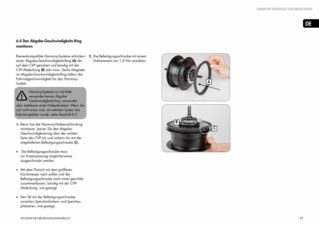
6.4 Den Abgabe-Geschwindigkeits-Ring montieren
Riemenkompatible Harmony-Systeme erfordern einen Abgabe-Geschwindigkeits-Ring (A) der auf dem CVP gesichert und bündig mit der CVP-Abdeckung (B) sein muss. Sechs Magnete im Abgabe-Geschwindigkeits-Ring liefern die Fahrradgeschwindigkeit für das Harmony-System.
1. Bevor Sie die Harmony-Nabenverbindung montieren, bauen Sie den Abgabe-Geschwindigkeitsring über der rechten Seite des CVP ein und sichern ihn mit der mitgelieferten Befestigungsschraube (C).
• Die Befestigungsschraube muss zur Ersteinpassung möglicherweise ausgeschraubt werden.
• Mit dem Flansch mit dem größeren Durchmesser nach außen und der Befestigungsschraube nach innen gerichtet zusammenbauen, bündig mit der CVP-Abdeckung, wie gezeigt.
• Den Tel mit der Befestigungsschraube zwischen Speichenlöchern und Speichen platzieren, wie gezeigt.
B
C
A
Harmony-Systeme nur mit Kette verwenden keinen Abgabe-Geschwindigkeits-Ring, verwenden
aber stattdessen einen Nabenkodierer. Wenn Sie sich nicht sicher sind, mit welchem System das Fahrrad geliefert wurde, siehe Abschnitt 8.5.
!
HARMONY MONTAGE VON EINZELTEILEN
2. Die Befestigungsschraube mit einem Drehmoment von 1,0 Nm anziehen.

46
DE
TECHNISCHES BEDIENUNGSHANDBUCH
6.5 Den Naben-Kodierer montieren (Ältere Harmony-Systeme)
Ältere Harmony-Systeme nur mit Kette benötigen einen farblich passenden Nabenkodierer (A), der über der CVP-Abdeckung gesichert werden muss. Sechs Magnete im Nabenkodierer liefern die Fahrradgeschwindigkeit für das Harmony-System.
Riemenkompatible Harmony-Systeme verwenden keinen Abgabe-Geschwindigkeits-Kodierer, sondern
verwenden stattdessen einen Abgabe-Geschwindigkeits-Ring. Wenn Sie sich nicht sicher sind, welches System am Fahrrad montiert ist, siehe Abschnitt 8.5.
1. Richten Sie den Nabenkodierer über der rechten Seiter des CVPs aus, bevor Sie das Ritzel montieren.
• So montieren, dass die Magnete des Nabenkodierers zum CVP gerichtet sind, wie gezeigt.
• Richten Sie die Passfeder auf der rechten CVP-Abschirmung (B) mit der Aussparung (C) auf dem Nabenkodierer aus, wie gezeigt.
2. Montieren Sie den Naben-Kodierer, indem Sie ab der Stelle mit der Passfeder beginnen und den Nabenkodierer auf die rechte Abdeckung drücken.
• Bewegen Sie die Schnapp-Einpassung mit kontinuierlichem Druck herum auf die entgegengesetzte Seite zur Stelle mit der Passfeder.
• Der Nabenkodierer sollte fest und sicher sein, bündig mit dem CVP (D), wie gezeigt.
D
C
B
A
!
HARMONY MONTAGE VON EINZELTEILEN

47
DE
TECHNISCHES BEDIENUNGSHANDBUCH
B
D
E
C
A
Getriebenaben der Serien N330/N330f und N360/N380/N380SE haben unterschiedliche Aufnahmen
für Harmony Naben-Interfaces und sind nur mit bestimmten Harmony Naben-Interfaces kompatibel. Versuchen Sie nicht, ein Naben-Interface einzubauen, das nicht passt, da dies zu Schäden führt.
0° 0°
F20°
kompatible
kompatible
inkom
patib
le
D
inkompatible
!
Harmony HHI3 Naben-Interface
Harmony HHI8 Naben-Interface Harmony HISync Naben-Interface
N330/N330f Nabe
N360/N380/N380SE Nabe
HARMONY MONTAGE VON EINZELTEILEN
1. Achten Sie darauf, dass Sie das korrekte Harmony Naben-Interface für Ihre NuVinci Optimized Nabe haben.
• N330/N330f Naben sind mit einem gelben Punkt (A) markiert und sind ausschließlich mit einem Harmony HHI3 Naben-Interface (B, für Harmony 330 Produktgruppen) kompatibel.
• N360 und N380/N380SE Naben haben keinen gelben Punkt (C) und sind nur mit dem Harmony HHI8 und Harmony H|Sync Naben-Interface (D, für Harmony 380 und Harmony H|Sync Produktgruppen) kompatibel.
2. Verwenden Sie das noch nicht montierte Harmony Naben-Interface (E), um die gewünschte Ausrichtung zu bestimmen.
• Die übliche Ausrichtung ist nach vorne gerichtet, parallel zum Rahmen entlang der Ketten- oder der Sitzstrebe. Hauptanschluss zeigt nach vorne.
• Bewegen Sie das Harmony Naben-Interface innerhalb des rechten Ausfallendes auch auf horizontaler Ebene hin und her, um sicherzustellen, dass genügend Spiel für das Harmony Naben-Interface auch bei unterschiedlichen Positionen der Naben-Achse vorhanden ist.
3. Wenn das Harmony Naben-Interface im rechten Ausfallende korrekt ausgerichtet ist, entspricht der Einbauwinkel (F) dem angezeigten Winkel des Ausfallendes (in diesem Beispiel 20 Grad).
• Verwenden SIe die Markierungen auf dem Harmony Naben-Interface, um Ihren Einbauwinkel zu bestimmen.
6.6 Harmony Naben-Interface – Kompatibilität & Ausrichtung
48
DE
TECHNISCHES BEDIENUNGSHANDBUCH
6.7 Harmony Naben-Interface montieren
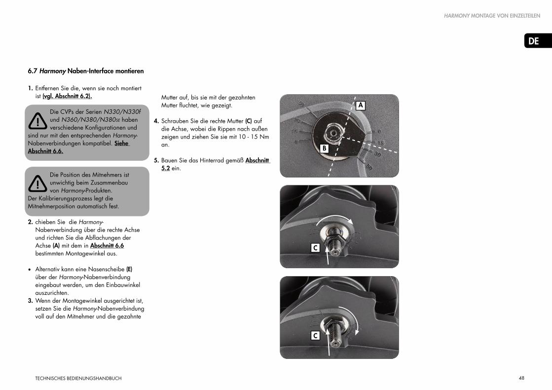
1. Entfernen Sie die, wenn sie noch montiert ist (vgl. Abschnitt 6.2).
Die CVPs der Serien N330/N330f und N360/N380/N380SE haben verschiedene Konfigurationen und
sind nur mit den entsprechenden Harmony-Nabenverbindungen kompatibel. Siehe Abschnitt 6.6.
Die Position des Mitnehmers ist unwichtig beim Zusammenbau von Harmony-Produkten.
Der Kalibrierungsprozess legt die Mitnehmerposition automatisch fest.
2. chieben Sie die Harmony-Nabenverbindung über die rechte Achse und richten Sie die Abflachungen der Achse (A) mit dem in Abschnitt 6.6 bestimmten Montagewinkel aus.
• Alternativ kann eine Nasenscheibe (E) über der Harmony-Nabenverbindung eingebaut werden, um den Einbauwinkel auszurichten.
3. Wenn der Montagewinkel ausgerichtet ist, setzen Sie die Harmony-Nabenverbindung voll auf den Mitnehmer und die gezahnte
Mutter auf, bis sie mit der gezahnten Mutter fluchtet, wie gezeigt.
4. Schrauben Sie die rechte Mutter (C) auf die Achse, wobei die Rippen nach außen zeigen und ziehen Sie sie mit 10 - 15 Nm an.
5. Bauen Sie das Hinterrad gemäß Abschnitt 5.2 ein.
A
B
C
C
!
!
HARMONY MONTAGE VON EINZELTEILEN

49
DE
TECHNISCHES BEDIENUNGSHANDBUCH
6.8 Den Harmony H8 Controller montieren
1. Bauen Sie den rechten Bremshebel den Anweisungen des Herstellers entsprechend ein.
2. Schieben Sie den Controller H8 (A) auf die Lenkerstange.
3. Montieren Sie den rechten Griff (B) den Anweisungen des Herstellers entsprechend auf den Lenker.
4. Positionieren Sie den Controller so, dass
die Anzeige (C) für der Fahrer sichtbar ist und dass das Seil nicht behindert wird.
• Ziehen sie den Klemmbolzen mit 2,0 - 2,5 Nm an.
Verwenden Sie beim Montieren der Lenkergriffe niemals Schmier- oder Lösungsmittel.
Achten Sie darauf, dass Controller und Bremshebel korrekt funktionieren und nicht behindert werden (wenn
nötig neu anpassen).
Niemals ohne Lenkergriffe fahren. Der Drehgriff des Schaltstücks könnte sich lösen. Das kann zu schweren
Verletzungen führen.
6.9 Den Controller Harmony H3 montieren
1. Der Controller H3 wird auf einer Gummiunterlage montiert, die neben dem Griff um eine Standard-Lenkerstange gewunden ist.
2. Verwenden Sie den mitgelieferten Gummi-O-Ring, um den Controller H3 zu sichern und so zu positionieren, dass die Anzeige für den Fahrer sichtbar ist und das Kabel nicht behindert wird.
• Der Controller H3 kann entweder an der rechten oder der linken Seite der Lenkerstange montiert werden.
C
A
B
!
!
!
HARMONY MONTAGE VON EINZELTEILEN

50
DE
TECHNISCHES BEDIENUNGSHANDBUCH
6.10 Harmony Elektrische Verbindungen
Eine Übersicht über die elektrischen Verbindungen von Harmony 330 und Harmony 380 wird unten gegeben:
Eine Übersicht über die elektrischen Verbindungen von Harmony H|Sync ist unten gegeben:
Y-Strang - Harmony-Nabenverbindung zum Tretlager (bb)-Bereich
Stromstrang - Batterie / Strom aus dem Elektrofahrradsystem zum Tretlager-Bereich
Fahrer Controller-Kabel - Lenkerstange zum BB-Bereich
Anschluss an Elektrofahrradstrom (vom Originalhersteller zu liefern)
Harmony Anschlüsse (geliefert)
18-44V
H|Sync Strang - direkt ans Elektrofahrrad-System angeschlossen für Strom und CAN-Kommunikaktion
H|Sync Anschlüsse (mitgeliefert)
HARMONY MONTAGE VON EINZELTEILEN

51
DE
TECHNISCHES BEDIENUNGSHANDBUCH
7. Harmony Wartungsanweisungen
7.1 Den Freilauf warten oder reparieren
1. Das Hinterrad gemäß Abschnitt 5.1 entfernen.
2. Entfernen Sie die Harmony-Nabenverbindung und den Harmony-Eingabe-Geschwindigkeits-Ring durch Umkehrung gemäß Abschnitt 6.7 und Abschnitt 6.3.
3. Siehe Explosionszeichnung in Abschnitt 8.3. Entfernen Sie den Schnappring des Ritzels (12), den Distanzring (13, wenn montiert) und das Ritzel (14).
4. Entfernen Sie den Schnappring (15) am Mitnehmer und entfernen Sie die Freilaufbaugruppe (16).
5. Verwenden Sie beim Warten oder Ersetzen ein mittelschweres Öl oder sehr leichtes, wasserabweisendes Fett und überprüfen Sie die Raste und die Federfunktion.
6. Entfernen Sie den inneren Schnappring (17), das Nadellager (18) und die rechte Abschirmung (19) wenn diese Bauteile ersetzt werden sollen.
7. Montieren Sie die gewarteten / neuen Freilaufkomponenten gemäß der Explosionszeichnung in Abschnitt 8.3.
HARMONY WARTUNG
8. Montieren Sie das Ritzel und die Harmony-Bestandteile gemäß Schritt 2. und 3. oben.
9. Montieren Sie das Hinterrad gemäß Abschnitt 5.2.
1918171615
15
18
19
15
16

52
DE
TECHNISCHES BEDIENUNGSHANDBUCH
7.2 Bremsen-Konfiguration entfernen
Siehe Explosionszeichnung in Abschnitt 8.3 für Nummerierung und Beschreibung.
Das Hinterrad entfernen gemäß Abschnitt 5.1.
Entfernen der Metallteile der Klemmrollenbremse
1. Entfernen Sie die Achsmutter (1) die linke Nasenscheibe (2) und die linke Mutter (3).
2. Sichern Sie das Rad und verwenden Sie Wartungswerkzeug N360T-BKAD-01, um den Bremsen-Sicherungsring (6) zu entfernen und entfernen Sie dann den Adapter der Klemmrollenbremse (7) vom CVP.
Entfernen der Metallteile der Felgenbremse
1. Entfernen Sie die Achsmutter (1), die linke Nasenscheibe (2), die linke Mutter (3) und die Tellerscheibe (4).
2. Mit einem dünnen, flachen Objekt aufstemmen und die Abdeckung der Felgenbremse entfernen (5).
Entfernen der Metallteile der Scheibenbremse
1. Entfernen Sie die Achsmutter (1), die linke Nasenscheibe (2), die linke Mutter (3) und die Tellerscheibe (4).
2. Sichern Sie das Rad und verwenden Sie Wartungswerkzeug N360T-BKAD-01, um den Bremsen-Sicherungsring (6) zu entfernen und entfernen Sie dann sowohl die Bremsenabschirmung (8) als auch den Bremsscheibenadapter (9) vom CVP.
!
HARMONY WARTUNG

53
DE
TECHNISCHES BEDIENUNGSHANDBUCH
7.3 Bremsen Konfigurationen montieren
Siehe Explosionszeichnung in Abschnitt 8.3 für Nummerierung und Beschreibung.
Montieren der Metallteile der Klemmrollenbremse
1. Montieren sie den Adapter (7) der Klemmrollenbremse und tragen Sie ein hochfestes Gewindesicherungs-Präparat (wie Loctite® 277™ oder gleichwertig) um einen kompletten Gewindegang des Bremssicherungsrings (6) herum auf.
2. Verwenden Sie Wartungswerkzeug N360T-BKAD-01, montieren Sie den Bremsen-Sicherungsring (6) und ziehen Sie ihn mit 55 - 65 Nm an.
3. Nachdem die Klemmrollenbremse montiert ist, die linke Mutter (3) montieren und mit 30 - 35 Nm anziehen.
Montieren der Metallteile der Felgenbremse
1. Drücken Sie die Abdeckung der Felgenbremse (5) in Position bis sie vollständig sitzt, gefolgt von der Tellerscheibe (4).
2. Die linke Mutter (3) montieren und mit 30 - 35 Nm.
HARMONY WARTUNG
Montieren der Metallteile der Scheibenbremse
1. Montieren sie den Adapter (9) der Scheibenbremse und die Bremsenabschirmung (8) und tragen Sie ein hochfestes Gewindesicherungs-Präparat (wie Loctite® 277™ oder gleichwertig) um einen kompletten Gewindegang des Bremsensicherungsrings (6) herum auf.
2. Verwenden Sie Wartungswerkzeug N360T-BKAD-01, montieren Sie den Bremsen-Sicherungsring (6) und ziehen Sie ihn mit 55 - 65 Nm an.
3. Die linke Mutter (3) montieren und mit 30 - 35 Nm anziehen.
!
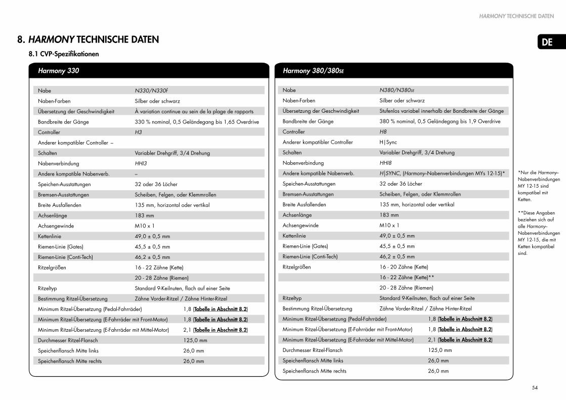
54
DE
TECHNISCHES BEDIENUNGSHANDBUCH
8. HARMONY TECHNISCHE DATEN
HARMONY TECHNISCHE DATEN
8.1 CVP-Spezifikationen
*Nur die Harmony--Nabenverbindungen MY 12-15 sind kompatibel mit Ketten.
**Diese Angaben beziehen sich auf alle Harmony--Nabenverbindungen MY 12-15, die mit Ketten kompatibel sind.
Harmony 330
Nabe N380/N380SE
Naben-Farben Silber oder schwarz
Übersetzung der Geschwindigkeit Stufenlos variabel innerhalb der Bandbreite der Gänge
Bandbreite der Gänge 380 % nominal, 0,5 Geländegang bis 1,9 Overdrive
Controller H8
Anderer kompatibler Controller H|Sync
Schalten Variabler Drehgriff, 3/4 Drehung
Nabenverbindung HHI8
Andere kompatible Nabenverb. H|SYNC, (Harmony--Nabenverbindungen MYs 12-15)*
Speichen-Ausstattungen 32 oder 36 Löcher
Bremsen-Ausstattungen Scheiben, Felgen, oder Klemmrollen
Breite Ausfallenden 135 mm, horizontal oder vertikal
Achsenlänge 183 mm
Achsengewinde M10 x 1
Kettenlinie 49,0 ± 0,5 mm
Riemen-Linie (Gates) 45,5 ± 0,5 mm
Riemen-Linie (Conti-Tech) 46,2 ± 0,5 mm
Ritzelgrößen 16 - 20 Zähne (Kette)
16 - 22 Zähne (Kette)**
20 - 28 Zähne (Riemen)
Ritzeltyp Standard 9-Keilnuten, flach auf einer Seite
Bestimmung Ritzel-Übersetzung Zähne Vorder-Ritzel / Zähne Hinter-Ritzel
Minimum Ritzel-Übersetzung (Pedal-Fahrräder) 1,8 (Tabelle in Abschnitt 8.2)
Minimum Ritzel-Übersetzung (E-Fahrräder mit Front-Motor) 1,8 (Tabelle in Abschnitt 8.2)
Minimum Ritzel-Übersetzung (E-Fahrräder mit Mittel-Motor) 2,1 (Tabelle in Abschnitt 8.2)
Durchmesser Ritzel-Flansch 125,0 mm
Speichenflansch Mitte links 26,0 mm
Speichenflansch Mitte rechts 26,0 mm
Harmony 380/380SE
Nabe N330/N330f
Naben-Farben Silber oder schwarz
Übersetzung der Geschwindigkeit À variation continue au sein de la plage de rapports
Bandbreite der Gänge 330 % nominal, 0,5 Geländegang bis 1,65 Overdrive
Controller H3
Anderer kompatibler Controller –
Schalten Variabler Drehgriff, 3/4 Drehung
Nabenverbindung HHI3
Andere kompatible Nabenverb. –
Speichen-Ausstattungen 32 oder 36 Löcher
Bremsen-Ausstattungen Scheiben, Felgen, oder Klemmrollen
Breite Ausfallenden 135 mm, horizontal oder vertikal
Achsenlänge 183 mm
Achsengewinde M10 x 1
Kettenlinie 49,0 ± 0,5 mm
Riemen-Linie (Gates) 45,5 ± 0,5 mm
Riemen-Linie (Conti-Tech) 46,2 ± 0,5 mm
Ritzelgrößen 16 - 22 Zähne (Kette)
20 - 28 Zähne (Riemen)
Ritzeltyp Standard 9-Keilnuten, flach auf einer Seite
Bestimmung Ritzel-Übersetzung Zähne Vorder-Ritzel / Zähne Hinter-Ritzel
Minimum Ritzel-Übersetzung (Pedal-Fahrräder) 1,8 (Tabelle in Abschnitt 8.2)
Minimum Ritzel-Übersetzung (E-Fahrräder mit Front-Motor) 1,8 (Tabelle in Abschnitt 8.2)
Minimum Ritzel-Übersetzung (E-Fahrräder mit Mittel-Motor) 2,1 (Tabelle in Abschnitt 8.2)
Durchmesser Ritzel-Flansch 125,0 mm
Speichenflansch Mitte links 26,0 mm
Speichenflansch Mitte rechts 26,0 mm

55
DE
HARMONY TECHNISCHE DATEN
8.2 Zugelassene Getriebeübersetzung (Übersetzungsverhältnis Kettenrad/Ritzel)
- 2.0 = Minimale Primärübersetzung für eBikes mit Mittel-Motor mit 350W Nennleistung oder darunter.
- 1.8 = Minimale Primärübersetzung für Pedelecs und eBikes mit Vorderrad-Naben-Motor.
- 0.80 = Minimale Primärübersetzung für Bosch GEN2 eBikes mit 350W Nennleistung oder darunter.
58 & höher
56
54
52
50
48
46
44
42
40
39
38
36
34
33
32
30
28
27 & niedriger
N330 CVP Zugelassene Getriebeübersetzung (Nfinity 330, Nfinity 330f & Harmony 330 Produktgruppen) N380 CVP Zugelassene Getriebeübersetzung(Nfinity 380, N380SE, Harmony 380/380SE and Harmony HISync Produktgruppen)
Stan
dard
Ket
tenr
ad /
Ritz
el
24 & höher
23
22
21
20
19
18
17
16
15
14
13 & niedriger
Bosc
h G
EN2
Kette
nrad
/ R
itzel
16 17 18 19 20 21 22 23 24 26 28 16 17 18 19 20 21 22 23 24 26 28
Für jedes Fahrrad zugelassen (eBikes mit Mittel-Motor bis einschließlich 250W) Für jedes Fahrrad zugelassen (eBikes mit Mittel-Motor bis einschließlich 250W)
N330 CVP (Nfinity 330, Nfinity 330f & Harmony 330 Produktgruppen)N380 CVP (Nfinity 380, Nfinity 380SE, Harmony 380/380SE & Harmony HISync Produktgruppen)
Primärübersetzung = Kettenrad / Ritzel Primärübersetzung = Kettenrad / RitzelFür kein Fahrrad zugelassen Für kein Fahrrad zugelassen
Nfinity 330, Nfinity 330f und Harmony 330 Systeme sind ausgestattet mit der N330 Nabe ausgestattet und
kompatibel mit eBikes mit Mittel-Motor bis einschließlich 250W unter Berücksichtigung der zulässigen Getriebeübersetzungen, wie in der entsprechenden Tabelle für die N330 Nabe dargestellt.
Nfinity 380, Nfinity 380SE und Harmony 380/380SE Systeme sind ausgestattet mit der N380 Nabe und
kompatibel mit eBikes mit Mittel-Motor bis einschließlich 350W, unter Berücksichtigung der zulässigen Getriebeübersetzungen, wie in der entsprechenden Tabelle für die N380 Nabe dargestellt.
! !Zugelassen für Fahrräder und eBikes mit Vorder-Naben-Motor (Nicht zugelassen für eBikes mit Mittel-Motor)
Zugelassen für Fahrräder und eBikesr mit Vorder-Naben-Motor (Nicht zugelassen für eBikes mit Mittel-Motor)
3,6 3,4 3,2 3,1 2,9 2,8 2,6 2,5 2,4 2,2 2,1
3,5 3,3 3,1 2,9 2,8 2,7 2,5 2,4 2,3 2,2 2,0
3,4 3,2 3,0 2,8 2,7 2,6 2,5 2,3 2,3 2,1 1,9
3,3 3,1 2,9 2,7 2,6 2,5 2,4 2,3 2,2 2,0 1,9
3,1 2,9 2,8 2,6 2,5 2,4 2,3 2,2 2,1 1,9 1,8
3,0 2,8 2,7 2,5 2,4 2,3 2,2 2,1 2,0 1,8 1,7
2,9 2,7 2,6 2,4 2,3 2,2 2,1 2,0 1,9 1,8 1,6
2,8 2,6 2,4 2,3 2,2 2,1 2,0 1,9 1,8 1,7 1,6
2,6 2,5 2,3 2,2 2,1 2,0 1,9 1,8 1,8 1,6 1,5
2,5 2,4 2,2 2,1 2,0 1,9 1,8 1,7 1,7 1,5 1,4
2,4 2,3 2,2 2,1 2,0 1,9 1,8 1,7 1,6 1,5 1,4
2,4 2,2 2,1 2,0 1,9 1,8 1,7 1,7 1,6 1,5 1,4
2,3 2,1 2,0 1,9 1,8 1,7 1,6 1,6 1,5 1,4 1,3
2,1 2,0 1,9 1,8 1,7 1,6 1,5 1,5 1,4 1,3 1,2
2,1 1,9 1,8 1,7 1,7 1,6 1,5 1,4 1,4 1,3 1,2
2,0 1,9 1,8 1,7 1,6 1,5 1,5 1,4 1,3 1,2 1,1
1,9 1,8 1,7 1,6 1,5 1,4 1,4 1,3 1,3 1,2 1,1
1,8 1,6 1,6 1,5 1,4 1,3 1,3 1,2 1,2 1,1 1,0
1,7 1,6 1,5 1,4 1,4 1,3 1,2 1,2 1,1 1,0 1,0
1,50 1,41 1,33 1,26 1,20 1,14 1,09 1,04 1,00 0,92 0,86
1,44 1,35 1,28 1,21 1,15 1,10 1,05 1,00 0,96 0,88 0,82
1,38 1,29 1,22 1,16 1,10 1,05 1,00 0,96 0,92 0,85 0,79
1,31 1,24 1,17 1,11 1,05 1,00 0,95 0,91 0,88 0,81 0,75
1,25 1,18 1,11 1,05 1,00 0,95 0,91 0,87 0,83 0,77 0,71
1,19 1,12 1,06 1,00 0,95 0,90 0,86 0,83 0,79 0,73 0,68
1,13 1,06 1,00 0,95 0,90 0,86 0,82 0,78 0,75 0,69 0,64
1,06 1,00 0,94 0,89 0,85 0,81 0,77 0,74 0,71 0,65 0,61
1,00 0,94 0,89 0,84 0,80 0,76 0,73 0,70 0,67 0,62 0,57
0,94 0,88 0,83 0,79 0,75 0,71 0,68 0,65 0,63 0,58 0,54
0,88 0,82 0,78 0,74 0,70 0,67 0,64 0,61 0,58 0,54 0,50
0,81 0,76 0,72 0,68 0,65 0,62 0,59 0,57 0,54 0,50 0,46
3,6 3,4 3,2 3,1 2,9 2,8 2,6 2,5 2,4 2,2 2,1
3,5 3,3 3,1 2,9 2,8 2,7 2,5 2,4 2,3 2,2 2,0
3,4 3,2 3,0 2,8 2,7 2,6 2,5 2,3 2,3 2,1 1,9
3,3 3,1 2,9 2,7 2,6 2,5 2,4 2,3 2,2 2,0 1,9
3,1 2,9 2,8 2,6 2,5 2,4 2,3 2,2 2,1 1,9 1,8
3,0 2,8 2,7 2,5 2,4 2,3 2,2 2,1 2,0 1,8 1,7
2,9 2,7 2,6 2,4 2,3 2,2 2,1 2,0 1,9 1,8 1,6
2,8 2,6 2,4 2,3 2,2 2,1 2,0 1,9 1,8 1,7 1,6
2,6 2,5 2,3 2,2 2,1 2,0 1,9 1,8 1,8 1,6 1,5
2,5 2,4 2,2 2,1 2,0 1,9 1,8 1,7 1,7 1,5 1,4
2,4 2,3 2,2 2,1 2,0 1,9 1,8 1,7 1,6 1,5 1,4
2,4 2,2 2,1 2,0 1,9 1,8 1,7 1,7 1,6 1,5 1,4
2,3 2,1 2,0 1,9 1,8 1,7 1,6 1,6 1,5 1,4 1,3
2,1 2,0 1,9 1,8 1,7 1,6 1,5 1,5 1,4 1,3 1,2
2,1 1,9 1,8 1,7 1,7 1,6 1,5 1,4 1,4 1,3 1,2
2,0 1,9 1,8 1,7 1,6 1,5 1,5 1,4 1,3 1,2 1,1
1,9 1,8 1,7 1,6 1,5 1,4 1,4 1,3 1,3 1,2 1,1
1,8 1,6 1,6 1,5 1,4 1,3 1,3 1,2 1,2 1,1 1,0
1,7 1,6 1,5 1,4 1,4 1,3 1,2 1,2 1,1 1,0 1,0
58 & höher
56
54
52
50
48
46
44
42
40
39
38
36
34
33
32
30
28
27 & niedriger
Stan
dard
Ket
tenr
ad /
Ritz
el
24 & höher
23
22
21
20
19
18
17
16
15
14
13 & niedriger
Bosc
h G
EN2
Kette
nrad
/ R
itzel
- 2.1 = Minimale Primärübersetzung für eBikes mit Mittel-Motor mit 250W Nennleistung oder darunter.
- 1.8 = Minimale Primärübersetzung für Pedelecs und eBikes mit Vorderrad-Naben-Motor.
- 0.84 = Minimale Primärübersetzung für Bosch GEN2 eBikes mit 250W Nennleistung oder darunter.
1,50 1,41 1,33 1,26 1,20 1,14 1,09 1,04 1,00 0,92 0,86
1,44 1,35 1,28 1,21 1,15 1,10 1,05 1,00 0,96 0,88 0,82
1,38 1,29 1,22 1,16 1,10 1,05 1,00 0,96 0,92 0,85 0,79
1,31 1,24 1,17 1,11 1,05 1,00 0,95 0,91 0,88 0,81 0,75
1,25 1,18 1,11 1,05 1,00 0,95 0,91 0,87 0,83 0,77 0,71
1,19 1,12 1,06 1,00 0,95 0,90 0,86 0,83 0,79 0,73 0,68
1,13 1,06 1,00 0,95 0,90 0,86 0,82 0,78 0,75 0,69 0,64
1,06 1,00 0,94 0,89 0,85 0,81 0,77 0,74 0,71 0,65 0,61
1,00 0,94 0,89 0,84 0,80 0,76 0,73 0,70 0,67 0,62 0,57
0,94 0,88 0,83 0,79 0,75 0,71 0,68 0,65 0,63 0,58 0,54
0,88 0,82 0,78 0,74 0,70 0,67 0,64 0,61 0,58 0,54 0,50
0,81 0,76 0,72 0,68 0,65 0,62 0,59 0,57 0,54 0,50 0,46

56
DE
TECHNISCHES BEDIENUNGSHANDBUCH
8.3 Explosionszeichnung
18 16 14 12 10
19 17 15 13 11 2Ausstattung mit Felgenbremse
Ausstattung mit Klemmrollenbremse
Ausstattung mit Scheibenbremse
Achsmutter
Nasenscheibe
Linke Mutter
Tellerscheibe
Abdeckung Felgenbremse
Bremsen-Sicherungsring
Klemmrollen-Adapter
Bremsen-Abschirmung
Scheibenbremsen-Adapter
Rechte Mutter
Nabenverbindung
1Ritzel-Schnappring
Ritzel-Distanzring
Ritzel
Schnappring (Freilauf)
Montage Freilauf
Schnappring (innen)
Nadellager
Rechte Abschirmung
A
B
C
1
2
3
4
5
6
7
8
9
10
11
12
13
14
15
16
17
18
19
7
9
48
6
4 5
1
2
3
A
B
C
(Optional - mit 2,3 mm breiten Ritzeln zu verwenden)
Nicht mitgeliefert
Linke (Fahr-)Seite Rechte (Fahr-)Seite
1
HARMONY TECHNISCHE DATEN

57
DE
TECHNISCHES BEDIENUNGSHANDBUCH
8.4 CVP & Harmony Schaltstück-Abmessungen
H3 Controller H8 Controller
CVP mit Harmony-Nabenverbindung CVP mit Harmony-Nabenverbindung Harmony-Nabenverbindung
12532 AND 36 SPOKECONFIGURATIONS
AVAILABLE
2.9SPOKEHOLE
SCALE 0.500
SCALE 0.500
183 AXLE WIDTH
135 DROPOUT WIDTH
VERSIONDISC BRAKE
ISO 6 BOLT16.0
41
73
67.5CENTERLINE
49.0CHAINLINE
26.026.0
MULTI-GEAR(2.3MM OR 3/32")CHAINS ANDSPROCKETS ONLY
HARMONY TECHNISCHE DATEN

58
DE
TECHNISCHES BEDIENUNGSHANDBUCH
8.5 "Nur Kette" und "Riemen-kompatibel" Harmony-Systeme
1. Erkennen von Harmony-Systemen "nur mit Kette":
• Herstellung zwischen 2011 - 2015.
• Harmony-Systeme "nur mit Kette" umfassen einen Naben-Kodierer (A), der auf der Vorderseite der CVP-Abdeckung montiert ist und farblich zum CVP passt (silber oder schwarz).
• Harmony-Systeme "nur für Kette" sind nur mit 16-20 Zahn-Stahlkettenritzeln kompatibel.
A
B
C
A
B
C
2. Erkennen von "riemenkompatiblen" Harmony-Systemen:
• Hergestellt ab 2015 bis jetzt
• "Riemenkompatible" Harmony-Systeme umfassen einen Abgabe-Geschwindigkeits-Ring (B), der auf der CVP-Abdeckung montiert werden muss, immer in schwarz.
• "Riemenkompatible" Harmony-Systeme umfassen auch einen Eingabe-Geschwindigkeits-Ring (C), der über dem Ritzelschnappring montiert wird, immer in schwarz.
• "Riemenkompatible" Harmony--Systeme sind mit 16-28-Zahn Ritzeln für Ketten oder Riemen kompatibel.
HARMONY TECHNISCHE DATEN

59
DE
TECHNISCHES BEDIENUNGSHANDBUCH
HINWEIS AUF GEISTIGES EIGENTUM
9. Hinweis auf geistiges Eigentum
Die NuVinci Optimized N360, Harmony & Harmony H|Sync Steuergeräte
Hinweis Geistiges Eigentum
Durch Kaufen und/oder Verwenden der Komponenten NuVinci Optimized und/oder des Fahrrades, das sie enthält, stimmen Sie den folgenden Bedingungen zu. Wenn sie nicht durch diese Bedingungen gebunden sein wollen, müssen Sie die Komponenten NuVinci Optimized innerhalb von drei (3) Tagen an Ihren Händler zurückgeben, um die volle Erstattung zu erhalten. Die hiermit mitverkauften Komponenten NuVinci Optimized dürfen nur den begleitenden Anweisungen entsprechend und im Hinterrad eines Fahrrads für den Zweck einer gewöhnlichen und handelsüblichen Hinter-Nabe verwendet werden. Sie stimmen zu, die Komponenten NuVinci Optimized für keinen anderen Zweck zu verwenden, insbesondere nicht zum Nachbau oder zum Reverse-Engineering. Eine etwaige unzulässige Verwendung der Komponenten NuVinci Optimized wird nicht empfohlen, lässt alle gültigen Garantien erlöschen und in dem Maße, in dem eine solche Verwendung zu irgendwelchen Verbesserungen an oder Erfindungen mit diesen Bestandteilen führt, behält sich Fallbrook Technologies Inc. und seine Lizenznehmer eine gebührenfreie, weltweite, unbegrenzte, nichtexklusive Lizenz an allen Rechten an etwaigen Erfindungen oder Verbesserungen dieser Art vor, soweit dies unter gültigem Recht zulässig ist.
Die hiermit verkauften Komponenten NuVinci Optimized, einschließlich, aber nicht beschränkt auf hintere Nabe, Controller und Gangschalter werden durch die US-Patente 7,871,353; 7,885,747; 7,959,533; 8,321,097, 8,376,903; 8,398,518; 8,506,452; 8,626,409 und die europäischen Patente EP2171312; EP2234869, Dansk Patent N. 1954959, Spanisches Patent ES2424652, wie auch andere Patente geschützt. Weitere Patentanträge in den Vereinigten Staaten und im Ausland sind für Fallbrook Technologies Inc. und ihre Tochter Fallbrook Intellectual Property Co. LLC gestellt.
Die Harmony- und H|Sync-Produkte beinhalten auch Software, Firmware oder andere digitale Informationen (kollektiv als "Software" bezeichnet), die eingebettet sein können oder bei Fallbrook Technologies oder ihren zugelassenen Vertretern zum Gebrauch mit den Produkten zugelassen ist.
Die Software ist weltweit urheberrechtlich geschützt und unerlaubte Vervielfältigung, Darstellung, Verwendung, Veröffentlichung oder Anpassung ist ausdrücklich nicht gestattet.
Fallbrook, NuVinci, N360, Harmony, Harmony H|Sync und ihre stilisierten Logos und die damit verbundenen Elemente sind Warenzeichen oder eingetragene Warenzeichen von Fallbrook Technologies Inc.Bosch und Intuvia sind Handelsmarken der Robert Bosch GmbH.Alle Rechte vorbehalten. © 2015

60
DE
TECHNISCHES BEDIENUNGSHANDBUCH
GARANTIE
10. Garantie
DIE FOLGENDE FREIWILLIGE ZWEI-JAHRES-GARANTIE WIRD VON FALLBROOK TECHNOLOGIES INC. ("FALLBROOK") ANGEBOTEN UND GILT BEIM KAUF DER FOLGENDEN PRODUKTE: NUVINCI OPTIMIZED, N330, N330f, N360, N380, N380SE, C3, C8, C8S, H3, H8, NFINITY 330, NFINITY 330f, NFINITY 380, NFINITY 380SE, HARMONY 330, HARMONY 380, HARMONY 380SE, HARMONY H|SYNC, NFINITY HI, HHI3, HHI8, HHISYNC (ZUSAMMEN DIE “FALLBROOK PRODUKTE”).
NACH DEM RECHT EINIGER LÄNDER (z.B. DEUTSCHLAND, NIEDERLANDE) STEHEN KÄUFERN VON MANGELHAFTEN ODER MIT DEM KAUFVERTRAG NICHT ÜBEREINSTIMMENDEN PRODUKTEN GESETZLICHE GEWÄHRLEISTUNGSRECHTE ZU. DIESE RECHTE BERECHTIGEN DEN KÄUFER VON DEM VERKÄUFER KOSTENLOS REPARATUR, ERSATZ, ODER UNTER BESTIMMTEN VORAUSSETZUNGEN KAUFPREISMINDERUNG ODER RÜCKERSTATTUNG DES KAUFPREISES ZU VERLANGEN. DIESE FREIWILLIGE GARANTIE BEEINTRÄCHTIGT NICHT IHRE GESETZLICHEN GEWÄHRLEISTUNGSRECHTE. WENN SIE BEIM KAUF VON FALLBROOK PRODUKTEN IN EINEM DIESER LÄNDER LEBEN, STEHEN IHNEN DIE UNTEN BESCHRIEBENEN ANSPRÜCHE AUS DER GARANTIE VON FALLBROOK ZUSÄTZLICH ZU IHREN GESETZLICHEN GEWÄHRLEISTUNGSRECHTEN ZU. DIESE ANSPRÜCHE BESTEHEN NEBEN IHREN GESETZLICHEN GEWÄHRLEISTUNGSRECHTEN, SO DASS SIE FÜR DEN FALL, DASS IHR FALLBROOK-PRODUKT WÄHREND DES GARANTIEZEITRAUMS MANGELHAFT IST ODER MIT DEM KAUFVERTRAG NICHT ÜBEREINSTIMMT, ZWISCHEN IHREN GESETZLICHEN GEWÄHRLEISTUNGSRECHTEN UND IHREN RECHTEN AUS DER BEGRENZTEN GARANTIE VON FALLBROOK WÄHLEN KÖNNEN.
Was deckt diese Garantie ab?
Fallbrook Technologies Inc. (Fallbrook) leistet Garantie für alle Fallbrook-Produkte, die Material- oder Verarbeitungsfehler aufweisen. Diese Garantie bezieht sich nur auf den Originalkäufer und ist nicht übertragbar. (Einige Staaten oder Länder lassen keine Einschränkung der Garantie auf den Originalkäufer zu, deshalb gilt diese Einschränkung möglicherweise nicht für Sie). Wenn Sie ihr Fallbrook-Produkt als Teil eines anderen Produkts erworben haben, ersetzt diese Garantie in keiner Weise die Garantie oder Gewährleistung des Herstellers dieses Produkts oder erweitert sie, da jene Garantie oder Gewährleistung allein in der Verantwortung des Herstellers dieses Produkts liegt.
Wie lange ist diese Garantie gültig?
Die Garantie ist für zwei Jahre ab dem Datum des ursprünglichen Kaufs gültig.
Was wird Fallbrook unternehmen?
Fallbrook wird nach eigenem Ermessen entscheiden, ob die defekte Einheit repariert, ersetzt oder der Kaufpreis erstattet wird.
Was deckt diese Garantie nicht ab? Diese Garantie deckt Folgendes nicht ab:
• Normale Abnutzung an Bauteilen, die üblichem Verschleiß ausgesetzt sind, wie z.B. Gummidichtungen und -ringe, Rollen am Kettenspanner (wenn vorhanden), Drehgriff-Gummis und Schaltzüge.
• Schäden an Teilen, die nicht von Fallbrook oder mit Fallbrook verbundenen Unternehmen (§ 15 AktG) hergestellt wurden (wie z.B. Ausfallenden und Ketten).
• Die erforderliche Arbeit, um das Produkt wieder in das Fahrrad einzubauen oder anzupassen.
• Ein in irgendeinem anderen Gerät eingebautes Produkt, das per Definition kein Fahrrad ist. Tandems sind nicht abgedeckt.
• Ein Produkt, das falsch montiert und/oder nicht unter Beachtung der technischen Montagehandbücher für Nfinity bzw. Harmony Produktgruppen aufgebaut wurde. Diese sind unter http://www.nuvincicycling.com/de/service/downloads.html zu finden.
• Ein Produkt, das über den in den technischen Handbüchern (der NuVinci Optimized Harmony or Nfinity Gruppen) vorgesehenen Umfang zerlegt wurde.

61
DE
TECHNISCHES BEDIENUNGSHANDBUCH
GARANTIE
• Ein Produkt, das verändert wurde oder an dem die Seriennummer oder der Datumscode verändert, entstellt oder entfernt wurde.
• Ein anderes Produkt als die N330f, das ohne vorherige schriftliche Genehmigung von Fallbrook für gewerbliche Zwecke genutzt wird. Nur die N330f darf für angemessene gewerbliche Zwecke genutzt werden und diese Garantie ist für eine solche angemessene gewerbliche Nutzung auf ein (1) Jahr beschränkt.
• Schäden am Produkt: - die nach Einschätzung von Fallbrook durch Sturz, Aufprall oder Misshandlung des Produkts verursacht wurden - die durch die Verwendung des Produkts in, nach freier Einschätzung von Fallbrook, extremen Einsatzgebieten verursacht wurden (z.B. Downhill, Freeride, “North Shore”-Stil und BMX) - die durch Antreiben des Produkts mit Elektromotoren über 250 Watt für N330/N330f/N360 und über 350 Watt für N380/N380SE oder irgendeinen Antrieb des Produktes mit internen Verbrennungsmotoren verursacht wurden;
- die durch Nutzung des Produkts mit Elektromotoren von über 80Nm nominalem Drehmoment oder über 90Nm maximalem Drehmoment verursacht wurden; - die durch Nutzung des Produkts mit einem Gesamtgewicht (Fahrer, Last und Bike) von über 200kg verursacht wurden; - die durch die Nutzung des Produkts außerhalb der vorgeschriebenen Übersetzungen von 1.8 zu 1 für Standard Fahrräder und 2.1. zu 1 (N330/N330f) und 2.0 zu 1 (N360/N380/N380SE) für eBikes verursacht wurden; - die durch die Nutzung des Produkts bei Spannungen von über 50V verursacht wurden - die durch die Verwendung von Teilen verursacht wurden, die nicht kompatibel, geeignet und/oder von Fallbrook nicht für die Verwendung mit dem Produkt zugelassen wurden; - die während des Transports des Produkts aufgetreten sind.
Wie erhält man Anspruch aufGarantieleistungen?
Forderungen aufgrund dieser Garantie müssen über den Händler, bei dem das Fahrrad oder die NuVinci Optimized Komponente gekauft wurde oder über einen Händler von NuVinci Optimized Produkten gestellt werden. Bitte geben Sie das Produkt zusammen mit der datierten Originalrechnung oder Quittung an den Händler zurück. Der Händler nimmt mit dem Kundenservice von NuVinci CyclingKontakt auf, um Ihren Garantieanspruch zu bearbeiten. Händler, die einen Garantieanspruch geltend machen wollen, sollten sich an den NuVinci Cycling Kundendienst wenden, um eine Garantieleistungs-genehmigung zu erhalten. Der Händler muss dann dasProdukt zusammen mit einem ausreichenden Nachweis des Kaufdatums an NuVinci Cycling zurückschicken.

62
DE
TECHNISCHES BEDIENUNGSHANDBUCH
Limitierungen der Garantieleistung
DIESE BEGRENZTE GARANTIE IST DIE EINZIGE UND AUSSCHLIESSLICHE GARANTIE; DIE VON FALLBROOK IM HINBLICK AUF DAS PRODUKT GEGEBEN WIRD UNDWIRD AN STELLE EINER ETWAIGEN ANDEREN GARANTIE GEGEBEN. IM RAHMEN DES GÜLTIGEN RECHTS WERDEN ALLE AUSDRÜCKLICHEN ODER IMPLIZIERTEN GARANTIEN; DIE HIERIN NICHT ERWÄHNT WERDEN, AUSGESCHLOSSEN UND ABGELEHNT, EINSCHLIESSLICH ETWAIGER IMPLIZIERTER GARANTIEN VON ALLGEMEINER GEBRAUCHSTAUGLICHKEIT ODER EIGNUNG FÜREINEN SPEZIFISCHEN ZWECK. DIE HAFTBARKEIT VON FALLBROOK UNTER DIESER BEGRENZTEN GARANTIE IST AUSSCHLIESSLICH BEGRENZT AUF JENE HAFTUNG, DIE OBEN DARGELEGT WURDE. FÜR DEN FALL, DASS IRGENDEINE BESTIMMUNG DIESER BEGRENZTEN GARANTIE UNGÜLTIG SEIN ODER WERDEN SOLLTE, ODER UNTER GÜLTIGEM RECHT NICHT DURCHSETZBAR IST, BLEIBEN DIE BEDINGUNGEN DARIN VOLL GÜLTIG UND DIE UNGÜLTIGE ODER NICHT DURCHSETZBARE BESTIMMUNG SOLL SO UMGESTALTET WERDEN, DASS SIE GÜLTIG UND DURCHSETZBAR IST.
Fallbrook behält sich das Recht vor, diese begrenzte Garantie ohne vorherige Benachrichtigung zu ändern
GARANTIE
NuVinci CYCLINGNiederlassung Nordamerika
Fallbrook Technologies Inc.Cedar Park, Texas 78613 USA
USA toll free: 1-888-NuVinci (688-4624)
Tel: +1 (512) 279-6200 Fax: +1 (512) 267-0159
NuVinci CYCLINGSupport und Service in Europa
Fallbrook Technologies InternationalPopovstraat 128013 RK Zwolle, The Netherlands
Deutschland und Österreich+49 2289 2939 [email protected]
Schweiz+41 43 508 55 [email protected]
Allgemeiner Support Europa+31 38 7200 [email protected]

63
NL
TECHNISCHE GEBRUIKERSHANDLEIDING
TECHNISCHE GEBRUIKERSHANDLEIDING
NUVINCI OPTIMIZEDTM CVP METHARMONY AUTOMATISCH SCHAKELSYSTEEM
MANU-HRMY-00
EN
DE32-62
1-31
63-93
94-124
NL
FR
125-155 ES

64
NL
TECHNISCHE GEBRUIKERSHANDLEIDING
Inhoudsopgave
1. NuVinci Cycling - producten 65
1.1 Harmony 330, Harmony 380/380SE, en
Harmony H|Sync intelligente versnellingsnaven 65
1.2 The NuVinci Optimized CVP 65
2. Harmony 330 bediening & onderhoud 66
2.1 Harmony 330 System 66
2.2 Kalibreren van het Harmony 330-systeem 66
2.3 Upgraden van het Harmony 330-systeem 66
3. Harmony 380 bediening & onderhoud 67
3.1 Harmony 380/380SE-systeem 67
3.2 Kalibreren van het Harmony 380/380SE-systeem 67
4. Harmony H|Sync gebruik & onderhoud 68
4.1 Harmony H|Sync-systeem 68
4.2 Kalibreren van de Harmony H|Sync 68
4.3 Kalibreren van de Harmony H|Sync 69
5. Harmony algemeen onderhoud 70
5.1 Demontage van het achterwie 70
5.2 Montage van het achterwiel 71
5.3 Reinigen & smering 72
5.4 Slijtage van onderdelen en reparaties 72
6. Harmony assemblage van de componenten 73
6.1 Montage van het wiel 73
6.2 Installatie van het tandwiel 74
6.3 Installatie van de input-speed-ring 75
6.4 Installatie van de output-speed-ring 76
6.5 Installeren van de naafcodeur
(oudere Harmony-systemen) 77
6.6 Comptabiliteit van de Harmon-naafinterface 78
6.7 Installeren van de Harmony-naafinterface 79
6.8 Installatie van de Harmony H8-controller 80
6.9 Installatie van de Harmony H3-controlle 80
6.10 Harmony elektrische aansluitingen 81
7. Harmony onderhoudsinstructies 82
7.1 Onderhoud of vervanging van het freewheel 82
7.2 Verwijderen van de remconfiguraties 83
7.3 Installeren van remconfiguraties 84
8. Harmony technische gegevens 85
8.1 CVP-specificaties 85
8.2 Goedgekeurde overbrengingsverhoudingen 86
8.3 Explosietekening 87
8.4 CVP & Harmony draaischakelaardimensies 88
8.5 “Alleen ketting”- en “riemcompatibele”
Harmony -systemen 89
9. Kennisgeving betreffende intellectueel eigendom 90
10. Garantie 91
Europese support en onderhoud 93
Kantoor Noord-Amerika 93
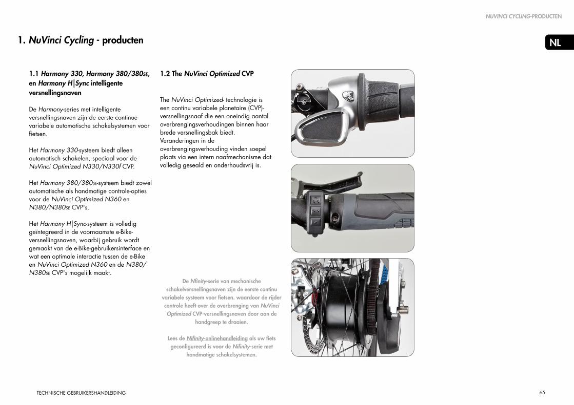
65
NL
TECHNISCHE GEBRUIKERSHANDLEIDING
1.1 Harmony 330, Harmony 380/380SE, en Harmony H|Sync intelligente versnellingsnaven
De Harmony-series met intelligente versnellingsnaven zijn de eerste continue variabele automatische schakelsystemen voor fietsen.
Het Harmony 330-systeem biedt alleen automatisch schakelen, speciaal voor de NuVinci Optimized N330/N330f CVP.
Het Harmony 380/380SE-systeem biedt zowel automatische als handmatige controle-opties voor de NuVinci Optimized N360 en N380/N380SE CVP's.
Het Harmony H|Sync-systeem is volledig geïntegreerd in de voornaamste e-Bike-versnellingsnaven, waarbij gebruik wordt gemaakt van de e-Bike-gebruikersinterface en wat een optimale interactie tussen de e-Bike en NuVinci Optimized N360 en de N380/N380SE CVP's mogelijk maakt.
1. NuVinci Cycling - producten
1.2 The NuVinci Optimized CVP
The NuVinci Optimized- technologie is een continu variabele planetaire (CVP)-versnellingsnaaf die een oneindig aantal overbrengingsverhoudingen binnen haar brede versnellingsbak biedt.Veranderingen in de overbrengingsverhouding vinden soepel plaats via een intern naafmechanisme dat volledig geseald en onderhoudsvrij is.
NUVINCI CYCLING-PRODUCTEN
De Nfinity-serie van mechanische schakelversnellingsnaven zijn de eerste continu
variabele systeem voor fietsen. waardoor de rijder controle heeft over de overbrenging van NuVinci Optimized CVP-versnellingsnaven door aan de
handgreep te draaien.
Lees de Nifinity-onlinehandleiding als uw fiets geconfigureerd is voor de Nifinity-serie met
handmatige schakelsystemen.

66
NL
TECHNISCHE GEBRUIKERSHANDLEIDING
2. Harmony 330 bediening & onderhoud
2.1 Harmony 330 System
• Het Harmony 330-systeem is alleen compatibel met de NuVinci Optimized N330/N330f CVP, en biedt te allen tijde automatisch schakelen voor de rijder.
• Het Harmony 330-systeem gebruikt de Harmony-H3-controller (A), die automatisch schakelen zo eenvoudig maakt dat alleen maar een knop hoeft te worden ingedrukt om uw pedaalcadans te kiezen. De cadansinstellingen (meestal laag, medium, hoog) zijn vooraf ingesteld door de fabrikant van de e-Bike conform het type fiets en de specificaties van de overbrengingsverhoudingen.
A
HARMONY 330 GEBRUIK & ONDERHOUD
2.2 Kalibreren van het Harmony 330-systeem
Als het Harmony-systeem opnieuw is geïnstalleerd, of als het systeem niet consistent of zelfs onjuist werkt, moet uw Harmony-330 -systeem opnieuw worden ingesteld.
Om dit te doen:
1. Zet het systeem aan.
2. Fiets tijdens het de gehele kalibratieprocedure rustig met de fiets (het makkelijkst gaat dit met een rollentrainer).
3. Druk tegelijk op de bovenste en onderste knop op de Harmony H3-controller en houd deze vast(B) totdat de achternaaf begint te schakelen (meestal 5-7 seconden), laat de knoppen daarna los.
4. Blijf licht doortrappen terwijl het systeem zelf meerdere malen van "laag" naar "hoog" schakelt en het kalibratieproces afrondt.
2.3 Upgraden van het Harmony 330-systeem
Harmony H3-controller naar de Harmony H8-controller, is het slechts een “plug and play”-installatie. Neem contact op met uw dealer of NuVinci Cycling onderhoud & support voor meer informatie.
B
De NuVinci Optimized CVP kan niet volledig door het totale overbrengingsbereik worden
geschakeld zonder de pedalen te bewegen. Het Harmony-systeem zal pas reageren als er een pedaalslag of beweging van het wiel wordt waargenomen indien grote veranderingen van de overbrengingsverhouding wordt gevraagd vanuit stilstand.
B
Bovenste & onderste knoppen
!
"Hoge" cadans
"Medium" cadans
"Lage" cadans

67
NL
TECHNISCHE GEBRUIKERSHANDLEIDING
3. Harmony 380/380SE bediening & onderhoud
3.1 Harmony 380/380SE-systeem
• Het Harmony 380/380SE- systeem is compatibel met NuVinci Optimized N360 en N380/N380SE CVP's (maar is incompatibel met de NuVinci Optimized N330/N330f CVP).
• Het Harmony 380/380SE- systeem gebruikt de Harmony H8-controller, die zowel volledig automatische als handmatige schakelopties biedt. De rijder kan schakelen tussen de modi “automatisch” en "handmatig" door op de knop "modus" (A) op de H8-behuizing te drukken.
• In de automatische modus past het Harmony 380/380SE-systeem automatisch de overbrengsverhouding aan zodat de fietser zijn gewenste cadans kan vasthouden. De fietser kan zijn ideale cadans instellen door aan de handgreep te draaien. De blauwe LED “RPM”-display geeft de cadansinstelling aan (B).
• In de handmatige modus kan de fietser zelf schakelen met behulp van de “ride by wire”- technologie. Net als bij het systeem dat met een kabel wordt bediend, geeft de oranje “heuvel” op de LED- display (C) dat hoe steiler de heuvel is, hoe lichter de versnelling om te kunnen klimmen is.
3.2 Kalibreren van het Harmony 380/380SE-systeem
Als het Harmony-systeem opnieuw is geïnstalleerd, of als het systeem niet consistent of zelfs onjuist werkt, moet uw Harmony 380-systeem opnieuw worden ingesteld.
Om dit te doen:
1. Zet het systeem aan.
2. Fiets tijdens het de gehele kalibratieprocedure rustig met de fiets (het makkelijkst gaat dit met een rollentrainer).
3. Druk op de "modus"-knop op de Harmony H8-controller en houd deze vast (A) totdat de achternaaf begint te schakelen (meestal 5-7 seconden), laat de knoppen daarna los.
4. Blijf licht doortrappen terwijl het systeem zelf meerdere malen van "laag" naar "hoog" schakelt en het kalibratieproces afrondt.
De NuVinci Optimized CVP kan niet volledig door het totale overbrengingsbereik worden
geschakeld bij stilstand. Het Harmony-systeem zal pas reageren als pedaalslag of beweging van het wiel wordt waargenomen indien grote veranderingen van de overbrengingsverhouding wordt gevraagd vanuit stilstand.
Modusknop A
CHandmatige modus
Lage versnelling voor klimmen
BAutomatische modus
Instellen hoge pedaalcadans
!
Instellen lage pedaalcadans
Hoge versnelling voor snelheid
HARMONY 380 GEBRUIK & ONDERHOUD

68
NL
TECHNISCHE GEBRUIKERSHANDLEIDING
4.2 Kalibreren van de Harmony H|SyncSysteem - algemeen
Als het Harmony-systeem opnieuw is geïnstalleerd, of als het systeem niet consistent of zelfs onjuist werkt, moet uw Harmony H|Sync- systeem opnieuw worden ingesteld.
Om dit te doen:
1. Zet het systeem aan.
2. Fiets tijdens het de gehele kalibratieprocedure rustig met de fiets (het makkelijkst gaat dit met een rollentrainer).
3. Start uw e-Bike Harmony H|Sync-kalibratie- Indien niet beschreven in de volgende paragrafen, zie de handleiding van uw e-Bike-systeem voor Harmony H|Sync kalibratie-instructies.
4. Blijf licht doortrappen terwijl het systeem zelf meerdere malen "laag" naar "hoog" schakelt en het kalibratieproces afrondt.
4. HARMONY H|SYNC gebruik & onderhoud
4.1 Harmony H|Sync-systeem
• The Het Harmony H|Sync-systeem is compatibel met NuVinci Optimized N360 en N380/N380SE CVP's (maar is incom-patibel met de NuVinci Optimized N330/N330f CVP).
• Het Harmony H|Sync-systeem is geïnte-greerd met het e-Bike-controlesysteem en biedt de mogelijkheid om automatisch en handmatig te schakelen.
• In de automatische modus past het Harm-ony H|Sync-systeem automatisch de over-brengingsverhouding aan zodat de rijder zijn gewenste cadans kan vasthouden. De rijder kan zijn ideale cadans instellen met behulp van de e-Bike-gebruikersinterface, zoals beschreven in de handleiding van het e-Bike-systeem.
• In de handmatige modus kan de fietser zelf schakelen met behulp van de “ride by wire”- technologie als de e-Bike-fabrikant dit heeft ondersteund. De rijder kan zijn ideale overbrengingsverhouding instellen met behulp van de e-Bike-gebruikersinter-face, zoals beschreven in de handleiding van het e-Bike-systeem.
HARMONY H|SYNC BEDIENING & ONDERHOUD
De NuVinci Optimized CVP kan niet volledig door het totale overbrengingsbereik worden
geschakeld bij stilstand. Het Harmony-systeem zal pas reageren als pedaalslag of beweging van het wiel wordt waargenomen indien grote veranderingen van de overbrengingsverhouding wordt gevraagd vanuit stilstand.
!

69
NL
TECHNISCHE GEBRUIKERSHANDLEIDING
HARMONY H|SYNC BEDIENING & ONDERHOUD
A
A
B
4.3 Kalibreren van de Harmony H|SyncSysteem - Bosch Intuvia
Als het Harmony-systeem opnieuw is geïnstalleerd, of als het systeem niet consistent of zelfs onjuist werkt, moet uw Harmony H|Sync- systeem opnieuwworden gekalibreerd.
Om dit op het Bosch Intuvia-systeem te doen:
1. Als alle componenten zijn aangesloten, kunt u het Bosch Intuvia-e-Bike-systeem aanzetten.
2. Schakel de Bosch Intuvia "configuratie"-modus in door de [ RESET ] - en [ i ] -knoppen (A) tegelijkertijd in te drukken en vast te houden.
3. Eenmaal in de “configuratie”-modus, drukt u op de [ i ] knop tot u “versnelling kalibratie -->” op de Intuvia-display ziet.
4. Begin snel maar licht te trappen met het achterwiel van de grond.
5. Terwijl u door blijft gaan met trappen, drukt u op de [ ] knop (B) om de kalibratie te beginnen
- ga door met snel maar licht trappen gedurende de procedure
6. Als het is afgerond, staat er "succes" op de display.
7. Verlaat de “configuratie” -modus door de [ RESET ]-knop in te drukken en vast te houden.

70
NL
TECHNISCHE GEBRUIKERSHANDLEIDING
5. Harmony algemeen onderhoud
5.1 Demontage van het achterwiel
Schakel de e-Bike “uit” en maak de accu van de e-Bike los (indien mogelijk).
1. Verwijder de hoofdstekker van de Harmony bij het achterwiel
- Pak de stekker vast waar hij geribbeld is (A) en trek licht weg van de Harmony-naafinterface.
2. Draai de asmoeren (B) los en verwijder ze samen met de onderlegringen (C) aan beide zijden.
- Bij velg- en rollerremapplicaties maakt u de achterrem los volgens de instructies van de fabrikant.
3. Verwijder het achterwiel.- Bij sommige fietsen moet de CVP-as en de
Harmony-naafinterface gedraaid worden om de fietsketting te verwijderen.
- In sommige gevallen is het het gemakkelijkst om de ketting van de voorste kettingring te verwijderen om het achterwiel gemakkelijker te verwijderen.
HARMONY ALGEMEEN ONDERHOUD
Trek niet aan de kabel, alleen aan de geribbelde stekker half zoals weerge-geven.
De stekker levert elektrische stroom aan de Harmony-naafinterface. Bescherm de stekker tegen water
of andere geleidende elementen indien niet aangesloten,omdat schok of schade aan het systeem kan ontstaan.
A
B
C
!
!
A

71
NL
TECHNISCHE GEBRUIKERSHANDLEIDING
5.2 Montage van het achterwiel
1. Plaats het achterwiel in het frame en let er daarbij op dat het draadloze huls van de Harmony en de hoofdstekker niet klem komen te zitten.
- Plaats de ketting om de Harmony-naafinterface en op het tandwiel.
- In sommige gevallen is het het gemakkelijkst om de ketting van de voorste kettingring te verwijderen om het achterwiel te installeren.
t
2. Schuif op een uiteinde van de as (B) een onderlegring. De gekartelde rand in de onderlegring moet tegen de uitvaleinde van het frame worden geplaatst De rechthoekige opstaande rand moet in het uitvaleinde van het frame vallen.
3. Monteer de asmoeren (C). Haal ze 7 aan met 30 - 40 Nm (266 - 350 in-lb).
- Bij velg- en rollerremapplicaties maakt u de achterrem vast volgens de instructies van de fabrikant.
4. Installeer de Harmony-hoofdstekker door de pijlen (D) tegenover elkaar te zetten en voorzichtig vast te drukken.
A
Bepaal de positie van de achterwielsnelheidssensor bt oss (A) op de Harmony-naaf interface. De
ketting mag niet vast komen te zitten op de sensor als het wiel geïnstalleerd. wordt.
B
D
C
A
!
D
HARMONY ALGEMEEN ONDERHOUD

72
NL
TECHNISCHE GEBRUIKERSHANDLEIDING
5.3 Reinigen & smering
• Uw NuVinci Optimized-componenten zijn geseald en goed beschermd tegen invloeden van buiten. Gebruik echter geen water onder druk (zoals een hogedrukreiniger of waterjets) voor het schoonmaken. Dit kan tot storingen leiden doordat er water doordringt.
• In de winter kunt u uw fiets beter iets vaker schoonmaken zodat strooizout geen schade kan aanbrengen.
• Gebruik geen agressieve reinigings- middelen.
• De NuVinci Optimized CVP is voorzien van een permanente smering en de interne onderdelen van de CVP zijn tijdens de gehele levensduur van het product onderhoudsvrij.
• Er kan wel onderhoud worden gepleegd aan het NuVinci Optimized CVP-interne freewheelmechanisme.
• Regelmatig smeren zal de levensduur van de ketting verlengen.
5.4 Slijtage van onderdelen en reparaties
• Handvatten, tandwielen en fietskettingen zijn onderdelen die aan slijtage onderhevig zijn. Controleer deze onderdelen regelmatig en vervang ze indien nodig.
• Noodzakelijke werkzaamheden aan de NuVinci Optimized CVP, het Nfinity schakelsysteem of het Harmony-schakelsysteemsysteem mogen uitsluitend worden uitgevoerd door een gekwalificeerde fietsendealer.
• Ongeautoriseerde werkzaamheden aan uw NuVinci Optimized CVP, het Nfinity-schakelsysteem of het Harmony-schakelsysteemsysteem kan uzelf in gevaar brengen en uw garantie laten vervallen.
• Neem contact op met uw gekwalificeerde fietsendealer als u vragen of problemen hebt.
• Kijk op onze website voor aanvullende onderhoudsinformatie op www.nuvincicycling.com/service
HARMONY ALGEMEEN ONDERHOUD

73
NL
TECHNISCHE GEBRUIKERSHANDLEIDING
6.1 Montage van het wiel
• The antischakelborgveer (A) zorgt voor 135 mm ruimte en moet op de CVP blijven tijdens het vastsnoeren en de montage van het wiel.
- De maximale spaakdiameter is #13/ 2.34 mm- De minimale spaakdiameter is #14/ 2.00 mm
• Voor het vastsnoeren wordt een patroon van twee kruizen aanbevolen voor 26 inch en 700c wielen.
- Gebruik alleen een patroon met 2 kruizen als de velg het toestaat dat de verbindingsstukken effectief in lijn zijn met de spaken.
• Voor 24 inch of kleinere wielen wordt een 1-kruis-patroon aanbevolen.
• Radiaal vastsnoeren wordt niet aanbevolen.
6. Harmony assemblage van de componenten
A
Installaties en reparaties moeten door een gekwalificeerde fietsenmaker worden uitgevoerd.
Deze paragraaf gaat uit van een kennis- en vaardighedenniveau dat overeenkomt met dat van een ervaren
fietsen monteur- of maker.
135 mm
!
!
HARMONY ASSEMBLAGE VAN DE COMPONENTEN

74
NL
TECHNISCHE GEBRUIKERSHANDLEIDING
• Zie paragraaf 8.1 (voor specificaties betreffende kettinglijn en riemlijn).
• De NuVinci Optimized CVP‘s zijn compatibel met 16 tot 28 tandwielen. Zie paragraaf 8.1 voor vereisten ten aanzien van tandwieloverbrengingverhouding en goedgekeurde overbrengingsverhoudingen.
3. Als een Harmony-naafinterface niet meteen na het tandwiel geïnstalleerd wordt, moet u de transportborging verwijderen (A).
6.2 Installatie van het tandwiel
1. Verwijder de transportborging (A) door deze stevig van de NuVinci CVP te trekken.
2. Installeer een standaard 9-tands 3/32 inch (2.3 mm) tandwiel (B) met de platte kant naar de CVP, gevolgd door geleverde tandwielspacer (C, indien vereist), en zet vast met tandwielborgring (D).
• De tandwielspacer is bedoeld voor spaken die 3/32 inch (2.3mm) dik zijn aan de binnenste doorsnede. Als de binnenste doorsnede 0.17-0.18 inch (4.3-4.5mm) dik is, mag de spacer niet gebruikt worden.
A
B
C
D
Gebruik van incompatibele CVP's kettingen kan de Harmony-naafinterface en de CVP
beschadigen CVP-componenten beschadigen en kan er een gevaarlijke situatie voor de rijder ontstaan.
NuVinci Optimized zijn incompatibel met 1/8 inch (3.18 mm) een-snelheid-kettingen en tandwielen die ten minste
aan een kant plat zijn. Gebruik alleen 3/32 inch (2.3 mm) kettingen en tandwielen.
Als het tandwiel asymmetrisch is, kan onjuiste installatie leiden tot beschadigingen aan de Harmony-
naaf interface en CVP-componenten en kan er een gevaarlijke situatie voor de rijder ontstaan.
!
!
!
HARMONY ASSEMBLAGE VAN DE COMPONENTEN
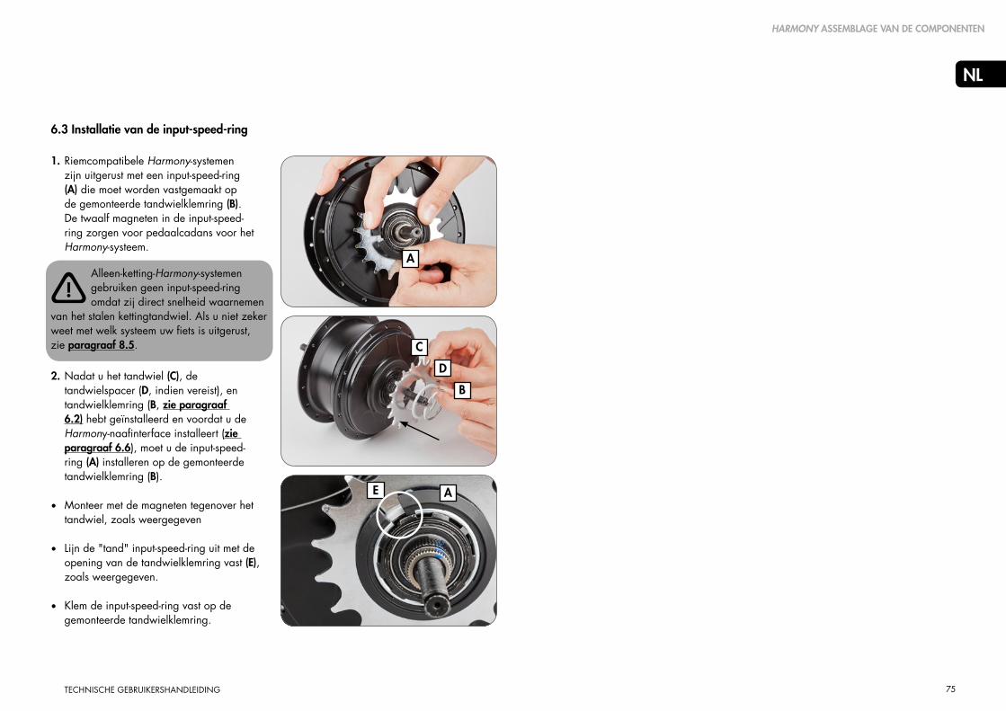
75
NL
TECHNISCHE GEBRUIKERSHANDLEIDING
6.3 Installatie van de input-speed-ring
1. Riemcompatibele Harmony-systemen zijn uitgerust met een input-speed-ring (A) die moet worden vastgemaakt op de gemonteerde tandwielklemring (B). De twaalf magneten in de input-speed-ring zorgen voor pedaalcadans voor het Harmony-systeem.
2. Nadat u het tandwiel (C), de tandwielspacer (D, indien vereist), en tandwielklemring (B, zie paragraaf 6.2) hebt geïnstalleerd en voordat u de Harmony-naafinterface installeert (zie paragraaf 6.6), moet u de input-speed-ring (A) installeren op de gemonteerde tandwielklemring (B).
• Monteer met de magneten tegenover het tandwiel, zoals weergegeven
• Lijn de "tand" input-speed-ring uit met de opening van de tandwielklemring vast (E), zoals weergegeven.
• Klem de input-speed-ring vast op de gemonteerde tandwielklemring.
B
C
D
A
E
Alleen-ketting-Harmony-systemengebruiken geen input-speed-ring omdat zij direct snelheid waarnemen
van het stalen kettingtandwiel. Als u niet zeker weet met welk systeem uw fiets is uitgerust, zie paragraaf 8.5.
A
!
HARMONY ASSEMBLAGE VAN DE COMPONENTEN

76
NL
TECHNISCHE GEBRUIKERSHANDLEIDING
6.4 Installatie van de output-speed-ring
Riemcompatibele Harmony-systemen vereisen een output-speed-ring (A) die moet worden vastgezet op de CVP, parallel aan de CVP-cover (B). Zes magneten in de output-speed.ring bieden fietssnelheid voor het Harmony- systeem.
1. Voor de installatie van de Harmony -naafinterface, moet u de output-speed-ring aan de rechterkant van de CVP monteren en vastzetten met de meegeleverde klem (C).
• De klem moet eventueel worden losgeschroefd om de montage mogelijk te maken.
• Monteer met de grotere flensdiameter aan de buitenkant en de klem aan de binnenkant, parallel aan de CVP-cover, zoals weergegeven.
• Bepaal de plaats van het klemgedeelte tussen spaakgaten en spaken, zoals weergegeven.
2. Draai de klem aan met 1.0 Nm (9 in-lbs).
B
C
A
Alleen-ketting-Harmony-systemen gebruiken geen output-speed-ring, maar wel een naafcodeur. Als u niet
zeker weet met welk systeem uw fiets isuitgerust, zie paragraaf 8.5.
!
HARMONY ASSEMBLAGE VAN DE COMPONENTEN

77
NL
TECHNISCHE GEBRUIKERSHANDLEIDING
6.5 Installeren van de naafcodeur (oudere Harmony-systemen)
Oudere “Alleen ketting” Harmony-systemen vereisen een naafcodeur in dezelfde kleur (A) die moet worden vastgezet op de CVP-cover. Zes magneten in de naafcodeur bieden fietssnelheid voor het Harmony-systeem.
Riemcompatibele Harmony-systemengebruiken geen output-speed-codeur, maar wel een output-speed-ring. Als
u niet zeker weet met welk systeem uw fiets is uitgerust, zie paragraaf 8.5. 1. Voor de installatie van het tandwiel,
moet u de naafinterface uitlijnen aan de rechterkant van de CVP.
• Monteer met de naafcodeurmagneten tegenover de CVP.
• Lijn de sleutel uit op de rechterafdekkap van de CVP (B) met de meeneemsleuf (C) op de naafcodeur, zoals weergegeven.
2. Installeer de naafcodeur door op de plaats van de sleutel te beginnen en de naafcodeur op de rechterafdekkap te drukken.
• “Wandel” met de druksluiting langs de tegenovergestelde kant van de sleutelpositie door continu te drukken.
• De naafcodeur moet strak en vastzitten, parallel aan de CVP (D), zoals weergegeven.
D
C
B
A
!
HARMONY ASSEMBLAGE VAN DE COMPONENTEN

78
NL
TECHNISCHE GEBRUIKERSHANDLEIDING
B
D
E
6.6 HarmonyTM Hub Interface Compatibility & Orientation1. Zorg ervoor dat u de juiste Harmony
naafinterface hebt voor uw NuVinci Optimized CVP.
• N330/N330f CVP's hebben een gele stip (A en zijn alleen compatibel met HHI3-naafinterfaces (B, voor Harmony-systemen).
• N360 en N380/N380SE CVP's hebben een zwarte schakelaandrijving (C) en zijn alleen compatibel met HHI8- en H|Sync-naafinterfaces (D, voor Harmony 380 en Harmony H|Sync- systemen).
2. Gebruik de niet geïnstalleerde Harmony-naafinterface (E) om de gewenste positie te bepalen.
• Oriëntatie is voorwaarts, parallel aan de kabelvoering en met de hoofdstekker voorwaarts.
• Beweeg de Harmony-naafinterface langs het uiteinden om speling te hebben op verschillende asposities.
3. Bij een correcte oriëntatie van de Harmony-naafinterface in het rechtertuitvaleinde, is de installatiehoek (F) gelijk aan de aangegeven hoek ten opzichte van de dropout (20 graden in dit voorbeeld).
• Gebruik de markeringen op de Harmony-naafinterface om bij benadering uw installatiehoek te bepalen.
C
A
6.6 Comptabiliteit van de Harmony-naafinterface & oriëntatie
N330/N330f en N360/N380/N380SE serie CVP's hebben verschillende
schakelaandrijvingconfiguraties, en zijn alleen compatibel met de juiste Harmony naafinterface. Probeer geen incorrecte Harmony-naafinterfaces te monteren, omdat hierdoor beschadigingen ontstaan.
0° 0°
F
20°
compatibel
compatibel
incom
patib
el
D
incompatibel
!
Harmony naafinterface 3
Harmony naafinterface 8 Harmony naafinterface Sync
N330/N330f CVP
N360/N380/N380SE CVP
HARMONY ASSEMBLAGE VAN DE COMPONENTEN

79
NL
TECHNISCHE GEBRUIKERSHANDLEIDING
6.7 Installeren van de Harmony naafinterface
1. Verwijder de transportborging, indien deze geïnstalleerd is. (Zie paragraaf 6.2)
N330/N330f en N360/N380/N380SE serie CVP's hebben verschillende schakelaandrijving
configuraties en zijn alleen compatibel met de juiste Harmony naafinterface. Zie paragraaf 6.6.
Schakelaandrijvingpositie maakt niet uit tijdens montage van de Harmony-producten; het kalibratieproces zal
automatisch de schakelaandrijvingpositie bepalen.
2. Zet de Harmony-naafinterface tijdelijk buiten werking aan de rechteras en lijn de platte zijden van de as uit (A) met de installatiehoek die bepaald is in paragraaf 6.6.
• Er kan ook een onderlegring (B) op de Harmony-naafinterface geïnstalleerd worden om de installatiehoek uit te lijnen.
3. Als de installatiehoek is uitgelijnd, schuif de Harmony naafinterface dan volledig over de schakelaandrijving en de spiebaan, zodanig dat deze parallel met de spiebanen staat, zoals is weergegeven.
A
B
C
C
!
!
HARMONY ASSEMBLAGE VAN DE COMPONENTEN
4. Voorzie de rechterasmoer van schroefdraad (C), de gekartelde randen naar buiten gericht, op de as en draai vast met 10- 15 Nm (7-11 ft-lbs).
5. Installeer het achterwiel zoals aangegeven in paragraaf 5.2.

80
NL
TECHNISCHE GEBRUIKERSHANDLEIDING
6.8 Installatie van de Harmony H8-controller
1. Monteer de rechterremhendel volgens de voorschriften van de fabrikant.
2. Schuif de H8-controller (A) op het stuur.
3. Monteer het rechterhandvat (B) op het stuur volgens de voorschriften van de fabrikant.
4. Positioneer de controller zodat de display (C) zichtbaar is voor de rijder en de kabel niet geblokkeerd wordt.
• Draai de klembout vast met 2.0-2.5 Nm (18- 22 in-lbs).
Gebruik nooit smeermiddelen of oplosmiddelen om de handvatten te monteren.
Controleer of de controller en de remhendel correct werken en niet geblokkeerd worden (indien nodig,
opnieuw afstellen).
Rijd nooit zonder handvatten. De draaigreep van de draaischakelaar zou eventueel los kunnen komen. Dit
kan leiden tot gevaarlijke verwondingen.
6.9 Installatie van de Harmony H3-controller
1. De H3-controller wordt op een rubber basis gemonteerd die om een standaard handgreep heen zit, aan de greep.
2. Gebruik de meegeleverde rubber o-ring om de H3-controller vast te zetten zodat de display zichtbaar is voor de rijder en de kabel niet geblokkeerd wordt.
• De H3 controller kan zowel aan de rechter -als linkerzijde van de handgreep gemonte-erd worden.
C
A
B
!
!
HARMONY ASSEMBLAGE VAN DE COMPONENTEN
!

81
NL
TECHNISCHE GEBRUIKERSHANDLEIDING
6.10 Harmony elektrische aansluitingen
Een overzicht van elektrische aansluitingenvan de Harmony H|Sync staat hieronder:
Een overzicht van elektrische aansluitingen van de Harmony H|Sync staat hieronder:
Y-harnas – Harmony-naafinterface naar trapasgebied
Vermogen harnas – accu / e-Bike-systeem stroom naar
Trapasgebied rijdercontrolekabel
Trapasgebiedaansluiting op e-Bike-stroom (OEM mee te leveren)
Harmony aansluitingen (meegeleverd)
18-44V
H|Sync-harnas – Maakt direct aansluiting met e-Bike- systeem voor stroom en CAN-communicatie
H|Sync-aansluitingen (meegeleverd)
HARMONY ASSEMBLAGE VAN DE COMPONENTEN

82
NL
TECHNISCHE GEBRUIKERSHANDLEIDING
7. Harmony onderhoudsinstructies
7.1 Onderhoud of vervanging van het freewheel
1. Verwijder het achterwiel zoals beschreven in paragraaf 5.1.
2. Verwijder de Harmony-naafinterface en Harmony-input-speed-ring zoals beschreven in paragraaf 6.7 en paragraaf 6.3.
3. Zie de explosietekening in paragraaf 8.3. Verwijder de klemring van het tandwiel (12), de tandwielspacer (13, indien geïnstalleerd), en het tandwiel (14).
4. Verwijder de klemring (15) op de draaischakelaar, en verwijder de freewheelconstructie (16).
5. Bij vervanging of onderhoud van het freewheel moet een u een medium zoals olie of licht waterbestendig vet gebruiken en de werking van de pen en de vering controleren.
6. Verwijder de binnenste klemring (17), de naaldlager (18), en de rechterafdekplaat (19) als deze componenten vervangen worden.
7. Installeer de onderhouden / nieuwe freewheelcomponenten volgens de explosietekening in paragraaf 5.3.
HARMONY ONDERHOUDSINSTRUCTIES
8. Installeer het tandwiel en de Harmony-componenten volgens stap 2 en stap 3 hierboven.
9. Installeer het achterwiel zoals beschreven in paragraaf 5.2.
1918171615
15
18
19
15
16

83
NL
TECHNISCHE GEBRUIKERSHANDLEIDING
7.2 Verwijderen van de remconfiguraties
Zie explosietekening in paragraaf8.3 voor nummers en beschrijvingen.
Verwijder het achterwiel zoals beschreven in paragraaf 5.1.
Verwijderen van de roller-brake-bevestiging
1. Verwijder de linkerasmoer (1), de linker-no-turn-onderlegring (2) en de linkermoer (3).
2. Zet het wiel vast en gebruik onderhoudsgereedschap N360T-BKAD-01 om de klemring van de rem (6) te verwijderen en verwijder de remadapter (7) van de CVP.
Verwijder de velgrembevestiging
1. Verwijder de linkerasmoer (1), de linker-no-turn-onderlegring (2), de linkermoer (3) en de schuin toelopende vulring (4).
2. Gebruik een dun, plat voorwerp en wrik hiermee de velremcover los (5).
Verwijderen van de schrijfrembevestiging
1. Verwijder de linkerasmoer (1), de linker-no-turn-onderlegring (2), de linkermoer (3) en de schuin toelopende vulring (4).
2. Zet het wiel vast en gebruik
onderhoudsgereedschap N360T-BKAD-01 om de klemring van de rem (6) te verwijderen, en verwijder daarna zowel de remcover (8) als de schijfremadapter (9) van de CVP.
!
HARMONY ONDERHOUDSINSTRUCTIES

84
NL
TECHNISCHE GEBRUIKERSHANDLEIDING
7.3 Installeren van remconfiguraties
Zie explosietekening in paragraaf8.3 voor nummers en beschrijvingen.
Installeren van roller-brake-bevestiging
1. Installeer de roller-brake-adapter (7) en gebruik een sterk schroefborgingsmiddel (vergelijkbaar met Loctite® 277™) en breng dit aan op de volledige draad van de klemring g (6).
2. Gebruik onderhoudsgereedschap N360T-BKAD-01 voor het installeren en aandraaien van de klemring (6) met 55-65 Nm (41-48 ft-lbs).
3. Na installatie van de roller brake de linkermoer (3) vastdraaien met 30-35 Nm (22- 26 ft-lbs.
Installeren van velgrembevestiging
1. Druk de velgremcover (5) op zijn plek totdat hij vastklemt en installeer vervolgens de schuin toelopende vulring (4).
2. Installeer en zet de linkermoer (3) vast met 30-35 Nm (22-26 ft-lbs).
Installeren van de schrijfrembevestiging
1. Installeer de schrijfremadapter (9)en remcover (8) en gebruik een sterk schroefborgingsmiddel (vergelijkbaar met Loctite® 277™) en breng dit aan op de volledige draad van de klemring (6).
2. Gebruik onderhoudsgereedschap
N360T-BKAD-01 voor het installeren en aandraaien van de klemring (6) met 55-65 Nm (41-48 ft-lbs).
3. Installeer en zet de linkermoer (3) vast met 30-35 Nm (22-26 ft-lbs).
!
HARMONY ONDERHOUDSINSTRUCTIES

85
NL
TECHNISCHE GEBRUIKERSHANDLEIDING
8. Harmony technische gegevens
HARMONY TECHNISCHE GEGEVENS
8.1 CVP-specificaties
*Harmony naafinterfaces MY12-15 zijn alleen compatibel met kettingen
**Deze gegevens hebben betrekking op alle Harmony naafinterfaces MY12-15 die alleen compatibel zijn met kettingen
Naaf N330/N330f
Naafkleuren Zilver of Zwart
Versnellingen Oneindig binnen het versnellingsbereik
Versnellingsbereik 330% nominaal, 0.5 underdrive tot 1.65 overdrive
Controller H3
Andere compatibele controllers –
Schakelen Variable draaigreep, ¾ draai
naafinterface HHI3
Andere compatibele HI‘s –
Spaakconfiguraties 32 of 36 gaats
Remconfiguraties schijf, velg of roller
Inbouwbreedte 135 mm, horizontaal of verticaal
Aslengte 183 mm
Schroefdraad as M10 x 1
Kettinglijn 49.0 ± 0.5 mm
Riemlijn (Conti-Tech) 45.5 ± 0.5 mm
Riemlijn (Conti-Tech) 46.2 ± 0.5 mm
Tandwielen 16-22 tands (ketting)
20-28 tands (riem)
Soort tandwiel Standaard 9-tands, plaat aan een kant
Tandwielverhoudingen Voortandwiel tanden / Achtertandwiel tanden
Tandwielverhoudingen minimum (pedaal-e-Bikes) 1.8 (Tabel in paragraaf 8.2)
Tandwielverhoudingen minimum (voormotor-e-Bikes) 1.8 (Tabel in paragraaf 8.2)
Tandwielverhoudingen minimum (middenmotor-e-Bikes) 2.1 (Tabel in paragraaf 8.2)
Flensdiameter 125,0 mm
Hart naaf tot linkerflens 26,0 mm
Hart naaf tot rechterflens 26,0 mm
Harmony 330
Naaf N380/N380SE
Naafkleuren Zilver of Zwart
Versnellingen Oneindig binnen het versnellingsbereik
Versnellingsbereik 380% nominaal, 0.5 underdrive tot 1.9 overdrive
Controller H8
Andere compatibele controllers H|Sync
Schakelen Variable draaigreep, ¾ draai
naafinterface HHI8
Andere compatibel HI‘s H|Sync, (Harmony-naafinterfaces MY12-15)*
Spaakconfiguraties 32 of 36 gaats
Remconfiguraties schijf, velg of roller
Inbouwbreedte 135mm, horizontaal of verticaal
Aslengte 183 mm
Schroefdraad as M10 x 1
Kettinglijn 49.0 ± 0.5 mm
Riemlijn (Conti-Tech) 45.5 ± 0.5 mm
Riemlijn (Conti-Tech) 46.2 ± 0.5 mm
Tandwielen 16-20 tands (ketting)
16-22 tands (ketting)**
20-28 tands (riem)
Soort tandwiel Standaard 9-tands, plaat aan een kant
Tandwielverhoudingen Voortandwiel tanden / Achtertandwiel tanden
Tandwielverhoudingen minimum (pedaal-e-Bikes) 1.8 (Tabel in paragraaf 8.2)
Tandwielverhoudingen minimum (voormotor-e-Bikes) 1.8 (Tabel in paragraaf 8.2)
Tandwielverhoudingen minimum (middenmotor-e-Bikes) 2.1 (Tabel in paragraaf 8.2)
Flensdiameter 125,0 mm
Hart naaf tot linkerflens 26,0 mm
Hart naaf tot rechterflens 26,0 mm
Harmony 380/380SE

86
NL
TECHNISCHE GEBRUIKERSHANDLEIDING
HARMONY TECHNISCHE GEGEVENS
8.2 Goedgekeurde overbrengingsverhoudingen
- 2.1 minimum tandwielverhouding voor middenmotor-e-Bikes met 250W bereik of lager
- 1.8 minimum tandwielverhouding voor alle fietsen en voormotor-eBikes
- 0.84 minimum tandwielverhouding voor Bosch GEN2 eBikes met 250W of lager
- 2.0 minimum tandwielverhouding voor middenmotor-e-Bikes met 350W bereik of lager
- 1.8 minimum tandwielverhouding voor alle fietsen en voormotor-eBikes
- 0.8 minimum tandwielverhouding voor Bosch GEN2 eBikes met 350W of lager
58 & hoger
56
54
52
50
48
46
44
42
40
39
38
36
34
33
32
30
28
27 & lager
N330 CVP goedgekeurde overbrengingsverhoudingen (Nfinity 330, Nfinity 330f & Harmony 330 productgroepen) N380 CVP Goedgekeurde overbrengingsverhoudingen (Nfinity 380, N380SE, Harmony 380/380SE, and Harmony HISync productgroepen)
Stan
daar
d vo
or k
ettin
grin
g /
tand
wie
l
24 & hoger
23
22
21
20
19
18
17
16
15
14
13 & lager
Bosc
h G
EN2
voor
zijd
e-ta
ndw
iel
16 17 18 19 20 21 22 23 24 26 28 16 17 18 19 20 21 22 23 24 26 28
Goedgekeurd voor iedere fiets (inclusief 250W middenmotor-eBikes) Goedgekeurd voor iedere fiets (inclusief 350W middenmotor-e-Bikes)
N330 CVP (Nfinity 330, Nfinity 330f & Harmony 330 productgroepen) N380 CVP (Nfinity 380, Nfinity 380SE, Harmony 380/380SE & Harmony HISync productgroepen)
Tandwielverhoudingen = kettingring voor / achtertandwiel Tandwielverhoudingen = kettingring voor / achtertandwielNiet goedgekeurd voor iedere fiets Niet goedgekeurd voor iedere fiets
Nfinity 330, Nfinity 330f en de Harmony 330 -systemen worden gecombineerd met
de N330 CVP en zijn compatibel met middenmotor-eBikes met 250W of lager, met goedgekeurde gearing zoals op de bijbehorende N330 tabel op deze pagina.
NFinity 380, NFinity 380SE en de Harmony 380/380SE -systemen worden
gecombineerd met de N380 CVP en zijn compatibel met middenmotor-eBikes met 350W of lager, met goedgekeurde gearing zoals op de bijbehorende N380 tabel op deze pagina.
! !Goedgekeurd voor fietsen en voornaaf-motor- eBikes (Niet goedgekeurd voor middenmotor-eBikes) Goedgekeurd voor fietsen en voornaaf-motor- eBikes (Niet goedgekeurd voor middenmotor-eBikes)
3,6 3,4 3,2 3,1 2,9 2,8 2,6 2,5 2,4 2,2 2,1
3,5 3,3 3,1 2,9 2,8 2,7 2,5 2,4 2,3 2,2 2,0
3,4 3,2 3,0 2,8 2,7 2,6 2,5 2,3 2,3 2,1 1,9
3,3 3,1 2,9 2,7 2,6 2,5 2,4 2,3 2,2 2,0 1,9
3,1 2,9 2,8 2,6 2,5 2,4 2,3 2,2 2,1 1,9 1,8
3,0 2,8 2,7 2,5 2,4 2,3 2,2 2,1 2,0 1,8 1,7
2,9 2,7 2,6 2,4 2,3 2,2 2,1 2,0 1,9 1,8 1,6
2,8 2,6 2,4 2,3 2,2 2,1 2,0 1,9 1,8 1,7 1,6
2,6 2,5 2,3 2,2 2,1 2,0 1,9 1,8 1,8 1,6 1,5
2,5 2,4 2,2 2,1 2,0 1,9 1,8 1,7 1,7 1,5 1,4
2,4 2,3 2,2 2,1 2,0 1,9 1,8 1,7 1,6 1,5 1,4
2,4 2,2 2,1 2,0 1,9 1,8 1,7 1,7 1,6 1,5 1,4
2,3 2,1 2,0 1,9 1,8 1,7 1,6 1,6 1,5 1,4 1,3
2,1 2,0 1,9 1,8 1,7 1,6 1,5 1,5 1,4 1,3 1,2
2,1 1,9 1,8 1,7 1,7 1,6 1,5 1,4 1,4 1,3 1,2
2,0 1,9 1,8 1,7 1,6 1,5 1,5 1,4 1,3 1,2 1,1
1,9 1,8 1,7 1,6 1,5 1,4 1,4 1,3 1,3 1,2 1,1
1,8 1,6 1,6 1,5 1,4 1,3 1,3 1,2 1,2 1,1 1,0
1,7 1,6 1,5 1,4 1,4 1,3 1,2 1,2 1,1 1,0 1,0
1,50 1,41 1,33 1,26 1,20 1,14 1,09 1,04 1,00 0,92 0,86
1,44 1,35 1,28 1,21 1,15 1,10 1,05 1,00 0,96 0,88 0,82
1,38 1,29 1,22 1,16 1,10 1,05 1,00 0,96 0,92 0,85 0,79
1,31 1,24 1,17 1,11 1,05 1,00 0,95 0,91 0,88 0,81 0,75
1,25 1,18 1,11 1,05 1,00 0,95 0,91 0,87 0,83 0,77 0,71
1,19 1,12 1,06 1,00 0,95 0,90 0,86 0,83 0,79 0,73 0,68
1,13 1,06 1,00 0,95 0,90 0,86 0,82 0,78 0,75 0,69 0,64
1,06 1,00 0,94 0,89 0,85 0,81 0,77 0,74 0,71 0,65 0,61
1,00 0,94 0,89 0,84 0,80 0,76 0,73 0,70 0,67 0,62 0,57
0,94 0,88 0,83 0,79 0,75 0,71 0,68 0,65 0,63 0,58 0,54
0,88 0,82 0,78 0,74 0,70 0,67 0,64 0,61 0,58 0,54 0,50
0,81 0,76 0,72 0,68 0,65 0,62 0,59 0,57 0,54 0,50 0,46
3,6 3,4 3,2 3,1 2,9 2,8 2,6 2,5 2,4 2,2 2,1
3,5 3,3 3,1 2,9 2,8 2,7 2,5 2,4 2,3 2,2 2,0
3,4 3,2 3,0 2,8 2,7 2,6 2,5 2,3 2,3 2,1 1,9
3,3 3,1 2,9 2,7 2,6 2,5 2,4 2,3 2,2 2,0 1,9
3,1 2,9 2,8 2,6 2,5 2,4 2,3 2,2 2,1 1,9 1,8
3,0 2,8 2,7 2,5 2,4 2,3 2,2 2,1 2,0 1,8 1,7
2,9 2,7 2,6 2,4 2,3 2,2 2,1 2,0 1,9 1,8 1,6
2,8 2,6 2,4 2,3 2,2 2,1 2,0 1,9 1,8 1,7 1,6
2,6 2,5 2,3 2,2 2,1 2,0 1,9 1,8 1,8 1,6 1,5
2,5 2,4 2,2 2,1 2,0 1,9 1,8 1,7 1,7 1,5 1,4
2,4 2,3 2,2 2,1 2,0 1,9 1,8 1,7 1,6 1,5 1,4
2,4 2,2 2,1 2,0 1,9 1,8 1,7 1,7 1,6 1,5 1,4
2,3 2,1 2,0 1,9 1,8 1,7 1,6 1,6 1,5 1,4 1,3
2,1 2,0 1,9 1,8 1,7 1,6 1,5 1,5 1,4 1,3 1,2
2,1 1,9 1,8 1,7 1,7 1,6 1,5 1,4 1,4 1,3 1,2
2,0 1,9 1,8 1,7 1,6 1,5 1,5 1,4 1,3 1,2 1,1
1,9 1,8 1,7 1,6 1,5 1,4 1,4 1,3 1,3 1,2 1,1
1,8 1,6 1,6 1,5 1,4 1,3 1,3 1,2 1,2 1,1 1,0
1,7 1,6 1,5 1,4 1,4 1,3 1,2 1,2 1,1 1,0 1,0
58 & hoger
56
54
52
50
48
46
44
42
40
39
38
36
34
33
32
30
28
27 & lager
Stan
daar
d vo
or k
ettin
grin
g /
tand
wie
l
24 & hoger
23
22
21
20
19
18
17
16
15
14
13 & lager
Bosc
h G
EN2
voor
zijd
e-ta
ndw
iel
1,50 1,41 1,33 1,26 1,20 1,14 1,09 1,04 1,00 0,92 0,86
1,44 1,35 1,28 1,21 1,15 1,10 1,05 1,00 0,96 0,88 0,82
1,38 1,29 1,22 1,16 1,10 1,05 1,00 0,96 0,92 0,85 0,79
1,31 1,24 1,17 1,11 1,05 1,00 0,95 0,91 0,88 0,81 0,75
1,25 1,18 1,11 1,05 1,00 0,95 0,91 0,87 0,83 0,77 0,71
1,19 1,12 1,06 1,00 0,95 0,90 0,86 0,83 0,79 0,73 0,68
1,13 1,06 1,00 0,95 0,90 0,86 0,82 0,78 0,75 0,69 0,64
1,06 1,00 0,94 0,89 0,85 0,81 0,77 0,74 0,71 0,65 0,61
1,00 0,94 0,89 0,84 0,80 0,76 0,73 0,70 0,67 0,62 0,57
0,94 0,88 0,83 0,79 0,75 0,71 0,68 0,65 0,63 0,58 0,54
0,88 0,82 0,78 0,74 0,70 0,67 0,64 0,61 0,58 0,54 0,50
0,81 0,76 0,72 0,68 0,65 0,62 0,59 0,57 0,54 0,50 0,46

87
NL
TECHNISCHE GEBRUIKERSHANDLEIDING
8.3 Explosietekening
18 16 14 12 10
19 17 15 13 11 2Velgremonfiguratie
Roller-brake-configuratie
Schijfremconfiguratie
Asmoer
No-turn-onderlegring
Linkerasmoer
Schuin toelopende vulring
Velgremcover
Klemring voor rem
Roller-brake-adapter
Remcover
Schijfremcover
Rechtermoer
Naafinterface
Tandwielklemring
Tandwielspacer
Tandwiel
Klemring (freewheel)
Freewheelconstructie
Klemring (binnenkant)
Naaldlager
Rechterafdekkap
A
B
C
1
2
3
4
5
6
7
8
9
10
11
12
13
14
15
16
17
18
19
7
9
48
6
4 5
1
2
3
A
B
C
(Optioneel- te gebruiken bij tandwielen met een dikte van 2,3 mm)
Niet meegeleverd
Linker- (niet-aangedreven) kant Rechter- (aangedreven) kant
1
HARMONY TECHNISCHE GEGEVENS

88
NL
TECHNISCHE GEBRUIKERSHANDLEIDING
8.4 CVP & Harmony draaischakelaardimensies
H3 controller H8 controller
CVP met Harmony Hub-naafinterface CVP met Harmony Hub-naafinterface Harmony-naafinterface
12532 AND 36 SPOKECONFIGURATIONS
AVAILABLE
2.9SPOKEHOLE
SCALE 0.500
SCALE 0.500
183 AXLE WIDTH
135 DROPOUT WIDTH
VERSIONDISC BRAKE
ISO 6 BOLT16.0
41
73
67.5CENTERLINE
49.0CHAINLINE
26.026.0
MULTI-GEAR(2.3MM OR 3/32")CHAINS ANDSPROCKETS ONLY
HARMONY TECHNISCHE GEGEVENS

89
NL
TECHNISCHE GEBRUIKERSHANDLEIDING
HARMONY TECHNICAL DATA
8.5 “Alleen ketting”- en “riemcompatibele” Harmony-systemen
1. Hoe u “alleen ketting” Harmony-systemen kunt identificeren.
• Geproduceerd van 2011 - 2015.
• “Alleen ketting” -Harmony-systemen bevatten een naafcodeur (A) die op de vlakke zijde van de CVP-cover wordt gemonteerd en die dezelfde kleur heeft als de CVP (zilver of zwart).
• “Alleen ketting”-Harmony-systemen zijn alleen compatibel met 16-20T -stalen-kettingwielensprockets only.
A
B
C
A
B
C
2. “Riemcompatibele" Harmony-systemen identificeren.
• Geproduceerd vanaf 2015-heden.
• “Riemcompatibele” Harmony-systemen bevatten een output-speed-ring (B) die op de CVP-cover gemonteerd wordt, altijd in zwart.
• “Riemcompatibele” Harmony systemen bevat ook een input-speed-ring (C) die op de klemring van het tandwiel gemonteerd wordt, altijd in zwart.
• “Riemcompatibele” Harmony systemen zijn compatibel met 16-28T -tandwielen voor kettingen of riemen.
90
NL
TECHNISCHE GEBRUIKERSHANDLEIDING
KENNISGEVING BETREFFENDE INTELLECTUEEL EIGENDOM
9. Kennisgeving betreffende intellectueel eigendom
De NuVinci Optimized N360, Harmony & Harmony H|Sync controle-eenheden
Kennisgeving betreffende intellectueel eigendom
Door deze NuVinci Optimized-componenten en/of de fiets waarin ze zijn opgenomen te kopen of te gebruiken, gaat u akkoord met de volgende voorwaarden. Als u niet gebonden wenst te zijn door deze voorwaarden moet u de NuVinci Optimized- componenten retourneren aan uw verkoper binnen drie (3) dagen voor een volledige terugbetaling. De hierbij verkochte NuVinci Optimized-componenten mogen alleen gebruikt worden in het achterwiel van een fiets als gewone en speciale achternaaf en in overeenstemming met de bijgeleverde instructies. U stemt ermee in om de NuVinci Optimized-componenten niet te gebruiken voor een ander doel, waaronder zonder beperking herontwikkeling of reproductie. Onbevoegd gebruik van de NuVinci Optimized-componenten wordt niet aanbevolen en zal alle toepasselijke garanties ongeldig maken en in de mate waarin zulk gebruik leidt tot verbeteringen aan of tot uitvindingen op basis van deze componenten, en in zoverre toegelaten onder de toepasselijke wetgeving, zal Fallbrook Technologies Inc. en zijn licentiehouders een royaltyvrije, wereldwijde, permanente,niet-exclusieve licentie hebben op alle rechten met betrekking tot alle uitvindingen of verbeteringen die aan deze componenten worden uitgevoerd.
De hierbij verkochte NuVinci Optimized-componenten inclusief maar niet beperkt totde achternaaf, controller en versnellingshendel, zijn beschermd door Amerikaanse octrooien 7,871,353;7,885,747; 7,959,533; 8,321,097, 8,376,903;8,398,518; 8,506,452; 8,626,409; Europese octrooien EP2171312; EP2234869; Deens octrooinr. 1954959; Spaans octrooinr. ES2424652; en andere octrooien. AndereAmerikaanse en buitenlandse octrooi-aanvragen zijn ingediend voor Fallbrook Technologies Inc. en haar dochteronderneming Fallbrook Intellectual Property Co. LLC.
De Harmony- en H|Sync- producten bevatten software, firmware en andere digitale informatie (samen de “Software”) die door Fallbrook Technologies of haar bevoegde vertegenwoordiger is ingebouwd of beschikbaar gesteld voor gebruik bij de producten.De Software is beschermd door copyrightwetgeving in iedere jurisdictie of land en alle niet geautoriseerde reproductie, tentoonstelling, gebruik, publicatie of aanpassing is strikt verboden.
Fallbrook, NuVinci, N360, Harmony, Harmony H|Sync en hun gestileerde logo’s en verbonden elementen zijn handelsmerken of geregistreerde handelsmerken van Fallbrook Technologies Inc.Bosch en Intuvia zijn handelsmerken van Robert Bosch GmbH
Alle rechten voorbehouden © 2015

91
NL
TECHNISCHE GEBRUIKERSHANDLEIDING
GARANTIE
10. Garantie
FALLBROOK TECHNOLOGIES INC. ("FALLBROOK") BIEDT GEDURENDE TWEE JAAR VRIJWILLIG DE VOLGENDE GARANTIE OP DE VOLGENDE PRODUCTEN: NUVINCI OPTIMIZED, N330, N330f, N360, N380, N380SE, C3, C8, C8S, H3, H8, NFINITY 330, NFINITY 330f, NFINITY 380, NFINITY 380SE, HARMONY 330, HARMONY 380, HARMONY 380SE, HARMONY H|SYNC, NFINITY HI, HHI3, HHI8, HHISYNC (HIERNA GEZAMENLIJK TE NOEMEN “FALLBROOK-PRODUCTEN”).
CONFORM HET RECHT VAN DE AFZONDERLIJKE LANDEN (BIJV. DUITSLAND, NEDERLAND) HEBBEN KOPERS VAN PRODUCTEN DIE GEBREKEN VERTONEN OF NIET OVEREENKOMEN MET DE KOOPOVEREENKOMST RECHT OP WETTELIJKE GARANTIE. UIT HOOFDE HIERVAN KAN DE KOPER JEGENS VERKOPER AANSPRAAK MAKEN OP GRATIS REPARATIE, VERVANGING OF ONDER BEPAALDE VOORWAARDEN KORTING OP OF TERUGGAVE VAN DE AANKOOPPRIJS. DEZE VRIJWILLIGE GARANTIE GAAT NIET TEN KOSTE VAN UW WETTELIJKE GARANTIEAANSPRAKEN. INDIEN U BIJ AANKOOP VAN FALLBROOK-PRODUKTEN WOONACHTIG BENT IN EEN VAN DEZE LANDEN, KUNT U NAAST UW WETTELIJKE GARANTIEAANSPRAKEN AANSPRAAK MAKEN OP DE ONDERSTAANDE RECHTEN UIT HOOFDE VAN DE GARANTIE VAN FALLBROOK. DEZE AANSPRAKEN BESTAAN NAAST UW WETTELIJKE GARANTIEAANSPRAKEN, WAARDOOR U, INDIEN UW FALLBROOK PRODUCT TIJDENS DE GARANTIETERMIJN GEBREKEN VERTOONT OF NIET OVEREENKOMT MET DE KOOPOVEREENKOMST, DE KEUZE HEEFT TUSSEN UW WETTELIJKE GARANTIEAANSPRAKEN OF UW RECHTEN UIT HOOFDE VAN DE BEPERKTE GARANTIE VAN FALLBROOK.
Wat wordt gedekt door deze garantie?
Fallbrook Technologies Inc. (Fallbrook) waarborgt alle Fallbrook producten die materiaal- of fabricagefouten vertonen. Uitsluitend de oorspronkelijke koper kan aanspraak maken op deze garantie. Deze is niet overdraagbaar. (In bepaalde landen of staten is beperking van de garantie tot de oorspronkelijke koper verboden. In dat geval is deze beperking mogelijk niet op u van toepassing.) Indien u uw Fallbrook product heeft verkregen als onderdeel van een ander product, vervangt deze garantie op geen enkele wijze de garantie of waarborg van de producent van dat product en vormt zij er evenmin een uitbreiding van, aangezien die garantie of waarborg uitsluitend tot de verantwoordelijkheid van de producent van dat product behoort.
Hoe lang geldt de garantie?
Deze garantie geldt gedurende twee jaar vanaf de datum van de oorspronkelijke aankoop.
Wat doet Fallbrook?
Fallbrook besluit zelf of de defecte eenheid vervangen of gerepareerd wordt dan wel of de aankoopprijs wordt geretourneerd.
Wat wordt niet gedekt door deze garantie? De garantie geldt niet voor het volgende:
• Normale slijtage van componenten die aan slijtage onderhevig zijn, zoals rubber afdichtingen en -ringen, rollen op de kettingspanner (indien aanwezig), rubber onderdelen van de draaigrepen en schakelgreep.
• Schade aan onderdelen die niet door Fallbrook of door met Fallbrook gelieerde ondernemingen (§ 15 AktG) gefabriceerd zijn (bijv. uitvalnaven en kettingen).
• Het arbeidsloon voor het opnieuw inbouwen in of aanpassen van het product aan de fiets.
• Producten die zijn ingebouwd in een ander apparaat dat geen fiets is. Tandems vallen niet onder de garantie.
• Onjuist en/of niet met inachtneming van de montagehandleiding voor Nfinity of Harmony-productgroepen gemonteerde of opgebouwde producten. Deze zijn te vinden via http://www.nuvincicycling.com/nl/service/downloads.html.
• Een product dat verder is gedemonteerd dan voorzien in de technische handboeken (van de NuVinci Optimized Harmony of Nfinity-groepen).
• Producten die gewijzigd zijn of waarvan het serienummer of de datumcode veranderd, beschadigd of verwijderd is.

92
NL
TECHNISCHE GEBRUIKERSHANDLEIDING
GARANTIE
• Een product, ander dan de N330f, dat wordt gebruikt voor commerciële doeleinden zonder voorafgaande schriftelijke toestemming van Fallbrook. Alleen N330f mag worden gebruikt voor redelijke commerciële doeleinden en deze garantie zal worden beperkt tot één (1) jaar voor dergelijk redelijk commercieel gebruik.
• Schade aan producten: - die naar het oordeel van Fallbrook is veroorzaakt door vallen, botsingen of onjuist gebruik van het product - die naar het oordeel van Fallbrook is veroorzaakt door extreme toepassingen (bijv. downhill, freeride, “North Shore” en BMX) - die is veroorzaakt door aandrijving van het product met elektromotoren met een vermogen van meer dan 250 Watt voor N330/N330f/N360 en meer dan 350 Watt voor N380/N380SE of aandrijving van het product met een interne verbrandingsmotor; - die is veroorzaakt door gebruik van het product met elektromotoren met een nominaal koppelmoment van meer dan 80Nm of een maximaal koppelmoment van 90Nm;
- die is veroorzaakt door het gebruik van het product met een totale belasting (berijder, bagage en fiets) van meer dan 200 kg; - die is veroorzaakt door gebruik van het product buiten de voorgeschreven overbrengingen van 1.8 tot 1 voor standaardfietsen en 2.1. tot 1 (N330/N330f) en 2.0 tot 1 (N360/N380/N380SE) voor e-bikes; - die is veroorzaakt door gebruik van het product bij vermogens van meer dan 50V - die is veroorzaakt door toepassing van onderdelen die niet compatibel zijn met, geschikt voor en/of door Fallbrook niet zijn toegestaan voor gebruik met het product; - die is ontstaan tijdens het transport van het product.
Hoe maak ik aanspraak op de garantie?
Aanspraken uit hoofde van deze garantie verlopen via de dealer bij wie de fiets of de NuVinci Optimized-componenten zijn gekocht of via de dealer bij wie de NuVinci Optimized-componenten zijn besteld. We verzoeken u vriendelijk het product tezamen met oorspronkelijke factuur met datum en/of kassabon te retourneren aan de dealer. De dealer neemt daarna contact op met de klantenservice van NuVinci Cycling om uw garantie-aanspraak in behandeling te nemen. Dealers met garantie-aanspraken moeten contact opnemen met de klantenservice van NuVinci Cycling voor toestemming. De dealer dient het product vervolgens terug te sturen naar NuVinci Cycling met voldoende bewijs van de aankoopdatum.

93
NL
TECHNISCHE GEBRUIKERSHANDLEIDING
WARRANTY
Beperkingen van de garantie
DEZE BEPERKTE GARANTIE IS DE ENIGE EN EXCLUSIEVE GARANTIE; FALLBROOK VERSTREKT DEZE VOOR HET PRODUCT EN DEZE TREEDT IN DE PLAATS VAN EVENTUELE ANDERE GARANTIES. IN HET KADER VAN HET TOEPASSELIJKE RECHT WORDEN ALLE UITDRUKKELIJKE OF IMPLICIETE GARANTIES DIE HIERIN NIET GENOEMD WORDEN UITGESLOTEN EN AFGEWEZEN, MET INBEGRIP VAN EVENTUELE IMPLICIETE GARANTIES OMTRENT DE ALGEMENE DEUGDELIJKHEID VOOR GEBRUIK OF GESCHIKTHEID VOOR EEN SPECIFIEK DOEL. DE AANSPRAKELIJKHEID VAN FALLBROOK UIT HOOFDE VAN DEZE BEPERKTE GARANTIE IS UITSLUITEND BEPERKT TOT DE HIERBOVEN GENOEMDE PUNTEN. INDIEN EEN BEPALING VAN DEZE BEPERKTE GARANTIE ONGELDIG BLIJKT OF WORDT OF NIET KAN WORDEN TOEGEPAST KRACHTENS HET TOEPASSELIJKE RECHT, BLIJVEN DE OVERIGE BEPALINGEN VOLLEDIG GELDEN EN WORDT DE ONGELDIGE OF NIET TOEPASBARE BEPALING DUSDANIG AANGEPAST DAT DEZE GELDIG EN TOEPASBAAR IS.
Fallbrook behoudt zich het recht voor deze beperkte garantie zonder aankondiging vooraf te wijzigen
NuVinci CYCLINGKantoor Noord-Amerika
Fallbrook Technologies Inc.Cedar Park, Texas 78613 USA
USA toll free: 1-888-NuVinci (688-4624)
Tel: +1 (512) 279-6200 Fax: +1 (512) 267-0159
NuVinci CYCLINGEuropese support en onderhoud
Fallbrook Technologies InternationalPopovstraat 128013 RK Zwolle, The Netherlands
Duitsland & Oostenrijk+49 2289 2939 [email protected]
Zwitserland+41 43 508 55 [email protected]
Algemene Support Europa+31 38 7200 [email protected]
94
FR
MANUEL TECHNIQUE D’UTILISATION
MANUEL TECHNIQUE D’UTILISATION
ENGRENAGE PLANÉTAIRE À VARIATION CONTINUE (CVP) NUVINCI OPTIMIZEDTM AVEC SYSTÈME DE CHANGEMENT DE VITESSES AUTOMATIQUE HARMONY
MANU-HRMY-00
EN
DE32-62
1-31
63-93
94-124
NL
FR
125-155 ES

95
FR
MANUEL TECHNIQUE D’UTILISATION
Table des matières
1. Produits NuVinci Cycling 96
1.1 Transmissions intelligentes Harmony 330,
Harmony 380/380SE et Harmony H|Sync 96
1.2 Le CVP NuVinci Optimized 96
2. Harmony 330 – Utilisation & entretien 97
2.1 Système Harmony 330 97
2.2 Calibrage du système Harmony 330 97
2.3 Amélioration du système Harmony 330 97
3. Harmony 380 - Utilisation & entretien 98
3.1 Système Harmony 380/380SE 98
3.2 Calibrage du système Harmony 380/380SE 98
4. Harmony H|SYNC - Utilisation & entretien 99
4.1 Système Harmony H|Sync 99
4.2 Calibrage du système Harmony H|Sync
- Généralités 99
4.3 Calibrage du système Harmony H|Sync
- Bosch Intuvia 100
5. Harmony - Entretien général 101
5.1 Démontage de la roue arrière 101
5.2 Montage de la roue arrière 102
5.3 Nettoyage & lubrification 103
5.4 Pièces d'usure & travaux de réparation 103
6. Harmony - Assemblage des composants 104
6.1 Construction de la roue 104
6.2 Installation du pignon 105
6.3 Installation du plateau de vitesse d'entrée 106
6.4 Installation du plateau de vitesse de sortie 107
6.5 Installation de l'encodeur du moyeu
(anciens systèmes Harmony) 108
6.6 Interface de moyeu Harmony
- Compatibilité & orientation 109
6.7 Installation de l'interface de moyeu Harmony 110
6.8 Installation du régulateur Harmony H8 111
6.9 Installation du régulateur Harmony H3 111
6.10 Harmony - Raccordements électriques 112
7. Harmony - Instructions pour l’entretien 113
7.1 Entretien ou remplacement de la roue libre 113
7.2 Démontage des freins 114
7.3 Montage des freins 115
8. Harmony - Données techniques 116
8.1 Spécifications du CVP 116
8.2 Engrenages autorisés 117
8.3 Vue éclatée 118
8.4 Dimensions du CVP et du dérailleur Harmony 119
8.5 Systèmes Harmony « À chaîne uniquement »
et « Compatible avec une courroie » 120
9. Droits de propriété intellectuelle 121
10. Garantie 122
Service après-vente en Europe 124
Bureau nord-américain 124

96
FR
MANUEL TECHNIQUE D’UTILISATION
1.1 Transmissions intelligentes Harmony 330, Harmony 380/380SE et Harmony H|Sync
La gamme de transmissions intelligentes Harmony incarne la première gamme de systèmes de changement de vitesses automatique à variation continue destinéeaux vélos.
Le système Harmony 330 offre un changement de vitesses exclusivement automatique pour le CVP NuVinci Optimized N330/N330f.
Le système Harmony 380/380SE comporte des options de contrôle manuel ou automatique pour les CVP des gammes NuVinci Optimized N360 et N380/N380SE.
Le système Harmony H|Sync est totalement intégré aux principaux systèmes de transmission des vélos électriques, emploie l'interface utilisateur du vélo électrique et assure une interaction optimale entre le vélo électrique et les CVP des gammes NuVinci Optimized N360 et N380/N380SE.
1. Produits NuVinci Cycling
1.2 Le CVP NuVinci Optimized
La technologie NuVinci Optimized est une transmission à engrenage planétaire à variation continue (CVP) offrant un nombre illimité de rapports au sein de sa vaste plage de rapports.Les passages de vitesses s'effectuent en douceur à l'intérieur du moyeu par le biais de dispositifs internes scellés à vie, qui ne nécessitent aucun entretien.
PRODUITS NUVINCI CYCLING
La gamme de transmissions à changement de vitesses mécanique Nfinity incarne la première
gamme de systèmes à variation continue destinée aux vélos et permet au cycliste de définir le rapport des CVP NuVinci Optimized en tournant simplement
la poignée du dérailleur.
Consultez le manuel Nfinity en ligne si votre vélo est équipé de systèmes de changement de vitesses
manuel de la gamme Nfinity.
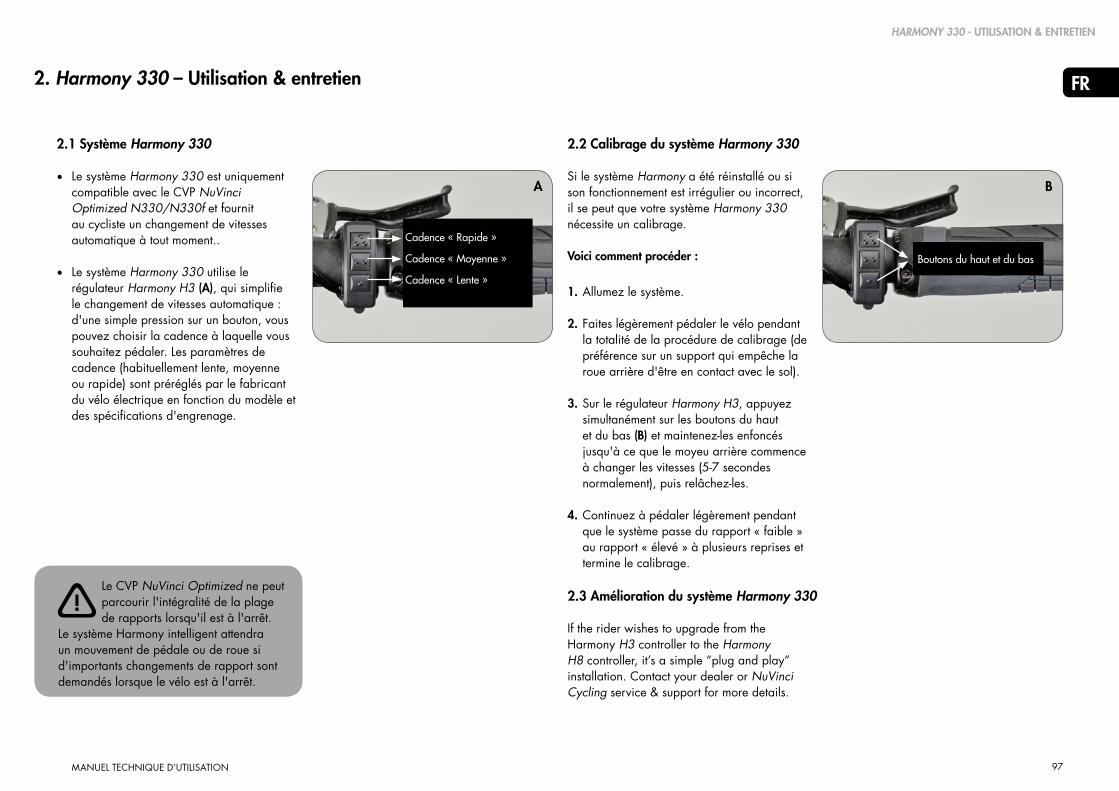
97
FR
MANUEL TECHNIQUE D’UTILISATION
2. Harmony 330 – Utilisation & entretien
2.1 Système Harmony 330
• Le système Harmony 330 est uniquement compatible avec le CVP NuVinci Optimized N330/N330f et fournit au cycliste un changement de vitesses automatique à tout moment..
• Le système Harmony 330 utilise le régulateur Harmony H3 (A), qui simplifie le changement de vitesses automatique : d'une simple pression sur un bouton, vous pouvez choisir la cadence à laquelle vous souhaitez pédaler. Les paramètres de cadence (habituellement lente, moyenne ou rapide) sont préréglés par le fabricant du vélo électrique en fonction du modèle et des spécifications d'engrenage.
A
HARMONY 330 - UTILISATION & ENTRETIEN
2.2 Calibrage du système Harmony 330
Si le système Harmony a été réinstallé ou si son fonctionnement est irrégulier ou incorrect, il se peut que votre système Harmony 330 nécessite un calibrage.
Voici comment procéder :
1. Allumez le système.
2. Faites légèrement pédaler le vélo pendant la totalité de la procédure de calibrage (de préférence sur un support qui empêche la roue arrière d'être en contact avec le sol).
3. Sur le régulateur Harmony H3, appuyez simultanément sur les boutons du haut et du bas (B) et maintenez-les enfoncés jusqu'à ce que le moyeu arrière commence à changer les vitesses (5-7 secondes normalement), puis relâchez-les.
4. Continuez à pédaler légèrement pendant que le système passe du rapport « faible » au rapport « élevé » à plusieurs reprises et termine le calibrage.
If the rider wishes to upgrade from the Harmony H3 controller to the Harmony H8 controller, it’s a simple “plug and play” installation. Contact your dealer or NuVinci Cycling service & support for more details.
B
Le CVP NuVinci Optimized ne peut parcourir l'intégralité de la plage de rapports lorsqu'il est à l'arrêt.
Le système Harmony intelligent attendra un mouvement de pédale ou de roue si d'importants changements de rapport sont demandés lorsque le vélo est à l'arrêt.
B
Boutons du haut et du bas
!
Cadence « Rapide »
Cadence « Moyenne »
Cadence « Lente »
2.3 Amélioration du système Harmony 330

98
FR
MANUEL TECHNIQUE D’UTILISATION
3. Harmony 380/380SE - Utilisation & entretien
3.1 Système Harmony 380/380SE
• Le système Harmony 380/380SE est compatible avec les CVP des gammes NuVinci Optimized N360 et N380 (mais pas avec le CVP NuVinci Optimized N330/N330f).
• Le système Harmony 380/380SE utilise le régulateur Harmony H8, options de changement de vitesses tant manuel qu'entièrement automatique. Le cycliste peut opter pour le mode « automatique » ou « manuel » en appuyant sur le bouton « mode » (A) sur le boîtier du régulateur H8.
• En mode automatique, Harmony 380/380SE ajuste automatiquement le rapport pour qu'il corresponde à la cadence favorite du cycliste. Ce dernier peut définir sa cadence idéale en tournant la poignée. L'écran à LED bleu indique le réglage de la cadence sous forme de « tours par minute » (B).
• En mode manuel, le cycliste peut changer lui-même les vitesses grâce à la technologie électronique « ride by wire ». À l'instar du système par câble, plus la « côte » orange affichée sur l'écran à LED (C) est inclinée, plus le rapport facilite son ascension.
3.2 Calibrage du système Harmony 380/380SE
Si le système Harmony a été réinstallé ou si son fonctionnement est irrégulier ou incorrect, il se peut que votre système Harmony 380/380SE nécessite un calibrage.
Voici comment procéder :
1. Allumez le système.
2. Faites légèrement pédaler le vélo pendant la totalité de la procédure de calibrage (de préférence sur un support qui empêche la roue arrière d'être en contact avec le sol).
3. Sur le régulateur Harmony H8, appuyez sur le bouton « mode » (A) et maintenez-le enfoncé jusqu'à ce que le moyeu arrière commence à changer les vitesses (5-7 secondes normalement), puis relâchez-le.
4. Continuez à pédaler légèrement pendant que le système passe du rapport « faible » au rapport « élevé » à plusieurs reprises et termine le calibrage.
Le CVP NuVinci Optimized ne peut parcourir l'intégralité de la plage de rapports lorsqu'il est à l'arrêt.
Le système Harmony intelligent attendra un mouvement de pédale ou de roue si d'importants changements de rapport sont demandés lorsque le vélo est à l'arrêt.
Bouton de mode A
CMode manuel
Easier ratio for climbing
BMode automatique
Réglage d'une cadence de pédalage plus élevée
!
Réglage d'une cadence de pédalage moins élevée
Faster ratio for speed
HARMONY 380 - UTILISATION & ENTRETIEN

99
FR
MANUEL TECHNIQUE D’UTILISATION
4.2 Calibrage du système Harmony H|Sync - Généralités
Si le système Harmony a été réinstallé ou si son fonctionnement est irrégulier ou incorrect, il se peut que votre système Harmony H|Sync nécessite un calibrage.
Voici comment procéder :
1. Allumez le système.
2. Faites légèrement pédaler le vélo pendant la totalité de la procédure de calibrage (de préférence sur un support qui empêche la roue arrière d'être en contact avec le sol).
3. Démarrez le calibrage du système Harmony H|Sync de votre vélo électrique. - S'il n'est pas repris dans les sections ci-dessous, consultez le manuel d'utilisation de votre vélo électrique pour obtenir les instructions de calibrage du système Harmony H|Sync.
4. Continuez à pédaler légèrement pendant que le système passe du rapport « faible » au rapport « élevé » à plusieurs reprises et termine le calibrage.
4. Harmony H|SYNC - Utilisation & entretien
4.1 Système Harmony H|Sync
• Le système Harmony H|Sync est compa-tible avec les CVP des gammes NuVinci Optimized N360 et N380/N380SE (mais pas avec le CVP NuVinci Optimized N330/N330f).
• Le système Harmony H|Sync est intégré au
système de commande du vélo électrique et offre la possibilité d'opter pour un mode de changement de vitesses automatique ou manuel.
• En mode automatique, Harmony H|Sync ajuste automatiquement le rapport pour qu'il corresponde à la cadence favorite du cycliste. Ce dernier peut choisir sa cadence idéale par le biais de l'interface utilisateur du vélo électrique, conformément aux instructions du manuel d'utilisation du vélo.
• Si le fabricant du vélo électrique en offre la possibilité, le mode manuel permet au cycliste de changer lui-même les vitesses grâce à la technologie électronique « ride by wire ». Ce dernier peut choisir son rapport idéal par le biais de l'interface utilisateur du vélo électrique, conformément aux instructions du manuel d'utilisation du vélo.
HARMONY H|SYNC - UTILISATION & ENTRETIEN
Le CVP NuVinci Optimized ne peut parcourir l'intégralité de la plage de rapports lorsqu'il est à l'arrêt.
Le système Harmony intelligent attendra un mouvement de pédale ou de roue si d'importants changements de rapport sont demandés lorsque le vélo est à l'arrêt.
!

100
FR
MANUEL TECHNIQUE D’UTILISATION
A
4.3 Calibrage du système Harmony H|Sync - Bosch Intuvia
Si le système Harmony a été réinstallé ou si son fonctionnement est irrégulier ou incorrect, il se peut que votre système Harmony H|Sync nécessite un calibrage.
Voici comment procéder avec le système Bosch Intuvia :
1. Lorsque tous les composants sont connectés, allumez le système Bosch Intuvia pour vélo électrique.
2. Activez le mode « Configuration » de Bosch Intuvia en appuyant simultanément sur les boutons [ RESET ] et [ i ] (A) et en les maintenant enfoncés.
3. Dès que vous vous trouvez en mode « Configuration », pressez le bouton [ i ] jusqu'à ce que l'indication
« Calibrage de l'engrenage --> » s'affiche sur l'écran.
4. Surélevez la roue arrière pour l'empêcher d'être en contact avec le sol et commencez à actionner les pédales du vélo rapidement mais avec légèreté.
A
B
HARMONY H|SYNC - UTILISATION & ENTRETIEN
5. Tout en continuant à pédaler, appuyez une fois sur le bouton [ ] (B) pour entamer le calibrage
- Continuez à pédaler rapidement mais avec légèreté tout au long de la procédure.
6. Lorsque celle-ci est terminée, l'écran indiquera « Réussi ».
7. Quittez le mode « Configuration » en appuyant longuement sur le bouton [ RESET ].

101
FR
MANUEL TECHNIQUE D’UTILISATION
5. Harmony - Entretien général
5.1 Démontage de la roue arrière
Éteignez le vélo électrique et déconnectez la batterie (si possible).
1. Enlevez le connecteur principal Harmony sur la roue arrière :
- Saisissez le connecteur à l'emplacement présentant des nervures (A) et extrayez-le délicatement de l’interface de moyeu Har-mony
2. Desserrez et enlevez les écrous d'axe (B) ainsi que les rondelles fixes (C) des deux côtés.
- Pour les modèles dotés de freins sur jante ou de freins à rouleau, déconnectez le frein arrière conformément aux instructions du fabricant.
HARMONY - ENTRETIEN GÉNÉRAL
Ne tirez pas sur le câble, saisissez uniquement l'extrémité nervurée du connecteur tel qu'indiqué sur
l'illustration.
Le connecteur alimente l'interface de moyeu Harmony en électricité. Évitez tout contact avec de l'eau ou d'autres
éléments conducteurs lorsqu'il est déconnecté; dans le cas contraire, cela pourrait entraîner un choc électrique ou endommager le système.
A
B
C
!
!
A
3. Enlevez la roue arrière.- Sur certains modèles, il est parfois
nécessaire d'effectuer une rotation de l'axe CVP et de l'interface de moyeu Harmony pour pouvoir enlever la chaîne du vélo.
- Dans certains cas, il est plus aisé d'enlever la chaîne du plateau avant afin de simplifier le démontage de la roue arrière.

102
FR
MANUEL TECHNIQUE D’UTILISATION
5.2 Montage de la roue arrière
1. Placez la roue arrière dans le cadre et assurez-vous que le faisceau de câbles ainsi que le connecteur principal du système Harmony ne soient ni entravés, ni coincés.
- Ajustez la chaîne autour de l'interface de moyeu Harmony et sur le pignon.
- Dans certains cas, il est plus aisé d'enlever la chaîne du plateau avant afin de simplifier l'installation de la roue arrière.
t
2. Enfilez une rondelle fixe (B) sur chaque extrémité de l'axe. La dentelure de la rondelle fixe doit reposer sur la patte du cadre. Le bossage rectangulaire doit être inséré dans les pattes du cadre.
3. Montez les écrous d'axe (C). Appliquez un couple de serrage de 30-40 Nm (266-350 po-lbs).
- Pour les modèles dotés de freins sur jante ou de freins à rouleau, connectez le frein arrière conformément aux instructions du fabricant.
4. Branchez le connecteur principal Harmony en alignant les flèches (D) et en les pressant ensemble avec précaution.
A
Identifiez le bossage du capteur de vitesse de la roue arrière (A) sur l'interface de moyeu Harmony. La
chaîne ne doit pas s'accrocher à ce capteur lors du montage de la roue.
B
D
C
A
!
D
HARMONY - ENTRETIEN GÉNÉRAL

103
FR
MANUEL TECHNIQUE D’UTILISATION
5.3 Nettoyage & lubrification
• Vos composants NuVinci Optimized sont scellés et parfaitement protégés des éléments extérieurs. Toutefois, n'utilisez pas d'eau pressurisée (comme des nettoyeurs haute pression ou des jets d'eau) pour le nettoyage afin d'éviter tout dysfonctionnement dû à une infiltration d'eau.
• Pendant l'hiver, nettoyez votre vélo plus souvent pour éviter que le sel d'épandage des routes n'occasionne des dégâts.
• N'employez pas de détergents agressifs.
• Le CVP NuVinci Optimized bénéficie d'une lubrification permanente et ses dispositifs internes ne nécessitent aucun entretien au cours de la durée de vie du produit.
• Le mécanisme de roue libre interne du CVP NuVinci Optimized est réparable.
• Un graissage régulier prolongera la durée de vie de la chaîne.
5.4 Pièces d'usure & travaux de réparation
• Les poignées du guidon, les pignons et les chaînes de vélo sont des pièces d'usure. Veuillez les contrôler régulièrement et les remplacer le cas échéant.
• Seul un revendeur qualifié est habilité à effectuer les travaux requis sur le CVP
NuVinci Optimized, le système de changement de vitesses Nfinity ou le
système de changement de vitesses Harmony.
• Réaliser des travaux non autorisés sur le CVP NuVinci Optimized, le système de changement de vitesses Nfinity ou le
système de changement de vitesses Harmony pourrait vous mettre en danger et annuler votre garantie.
• Veuillez contacter votre revendeur qualifié si vous avez une question ou rencontrez un problème.
• Consultez notre site web www.nuvinci.com pour toute information de service
supplémentaire.
HARMONY - ENTRETIEN GÉNÉRAL

104
FR
MANUEL TECHNIQUE D’UTILISATION
6.1 Construction de la roue
• Le disque de retenue anti-glissement (A) fournit un espace de 135 mm et doit rester sur le CVP durant le frettage et la construction de la roue.
- Le diamètre maximal du rayon s'élève à #13/ 2,34 mm
- Le diamètre minimal du rayon s'élève à #14/ 2,00 mm
• Le frettage conseillé est un modèle à double croisement pour les roues de 26 pouces et 700 c.
- Utilisez un modèle à double croisement uniquement si la jante permet aux écrous d'être effectivement alignés sur les rayons.
• Pour les roues de 24 pouces ou moins, il est conseillé d'utiliser un modèle à simple croisement.
• Le frettage radial n'est pas recommandé.
6. Harmony - Assemblage des composants
HARMONY - ASSEMBLAGE DES COMPOSANTS
A
L'installation et les réparations doivent être effectuées par un mécanicien spé-cialisé dans les vélos.
Cette section requiert un niveau de connaissances et d'expérience comparable à celui d'un assembleur
ou d'un mécanicien spécialisé dans les vélos.
135 mm
!
!

105
FR
MANUEL TECHNIQUE D’UTILISATION
• Voir section 8.1 (pour les spécifications relatives aux chaînes et courroies).
• Les CVP NuVinci Optimized
sont compatibles avec les pignons de 16 à 28 dents. Voir section 8.1 pour les exigences en matière de rapports de pignon et les engrenages autorisés.
3. Si l'interface de moyeu Harmony n'est pas installée directement après le pignon, replacez le disque de retenue anti-glissement (A).
6.2 Installation du pignon
1. Enlevez le disque de retenue anti-glissement (A) en le tirant fermement hors du CVP NuVinci.
2. Installez un pignon standard à 9 clavettes de 3/32 pouces (2,3 mm) (B) de façon à ce que le côté plat soit orienté vers le CVP, puis l'entretoise de pignon fournie (C, si nécessaire), avant de fixer l'ensemble à l'aide de la bague de serrage du pignon (D).
• L'entretoise de pignon est destinée aux pignons dont l'épaisseur du diamètre intérieur s'élève à 3/32 pouces (2,3 mm). Si l'épaisseur du diamètre intérieur équivaut à 0,17-0,18 pouce (4,3-4,5 mm), l'entretoise ne doit pas être utilisée.
A
B
C
D
L'emploi de chaînes incompatibles peut interférer avec l'interface de moyeu Harmony et endommager
les composants du CVP, mettant dès lors le cycliste en danger.
Les CVP NuVinci Optimized ne sont pas compatibles avec les chaînes et pignons de 1/8 pouce (3,18 mm)
à une seule vitesse qui sont plats sur l'un de leurs côtés au moins. Utilisez exclusivement des chaînes et pignons de 3/32 pouce (2,3 mm).
Si le pignon est asymétrique, une installation incorrecte peut interférer avec l'interface de moyeu Harmony
et endommager les composants du CVP, mettant dès lors le cycliste en danger.
!
!
!
HARMONY - ASSEMBLAGE DES COMPOSANTS
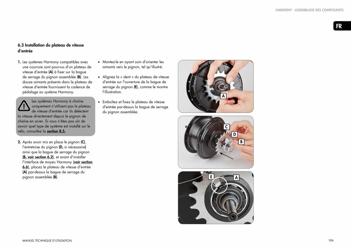
106
FR
MANUEL TECHNIQUE D’UTILISATION
6.3 Installation du plateau de vitesse d'entrée
1. Les systèmes Harmony compatibles avec une courroie sont pourvus d'un plateau de vitesse d'entrée (A) à fixer sur la bague de serrage du pignon assemblée (B). Les douze aimants présents dans le plateau de vitesse d'entrée fournissent la cadence de pédalage au système Harmony.
2. Après avoir mis en place le pignon (C), l'entretoise du pignon (D, si nécessaire) ainsi que la bague de serrage du pignon (B, voir section 6.2), et avant d'installer l'interface de moyeu Harmony (voir section 6.6), placez le plateau de vitesse d'entrée (A) par-dessus la bague de serrage du pignon assemblée (B).
B
C
D
A
E
Les systèmes Harmony à chaîne uniquement n'utilisent pas le plateau de vitesse d'entrée car ils détectent
la vitesse directement depuis le pignon de chaîne en acier. Si vous n'êtes pas sûr de savoir quel type de système est installé sur le vélo, consultez la section 8.5.
A
!
HARMONY - ASSEMBLAGE DES COMPOSANTS
• Montez-le en ayant soin d'orienter les aimants vers le pignon, tel qu'illustré.
• Alignez la « dent » du plateau de vitesse d'entrée sur l'ouverture de la bague de serrage du pignon (E), comme le montre l'illustration.
• Emboîtez et fixez le plateau de vitesse d'entrée par-dessus la bague de serrage du pignon assemblée.

107
FR
MANUEL TECHNIQUE D’UTILISATION
6.4 Installation du plateau de vitesse de sortie
Les systèmes Harmony compatibles avec une courroie requièrent un plateau de vitesse de sortie (A) à fixer sur le CVP, au même niveau que le couvercle du CVP (B).Les six aimants présents dans le plateau de vitesse de sortie fournissent la vitesse du vélo au système Harmony.
1. Avant de placer l'interface de moyeu Harmony, assemblez le plateau de vitesse de sortie sur le côté droit du CVP et assurez son maintien à l'aide du dispositif de fixation fourni (C).
• Il peut s'avérer nécessaire de dévisser le dispositif de fixation pour pouvoir l'emboîter.
• Procédez à l'assemblage en veillant à ce que la flasque de plus grand diamètre soit à l'extérieur et le dispositif de fixation à l'intérieur, au même niveau que le couvercle du CVP tel qu'illustré.
B
C
A
Les systèmes Harmony à chaîne uniquement n'utilisent pas le plateau de vitesse de sortie : ils emploient
plutôt un encodeur de moyeu. Si vous n'êtes pas sûr de savoir quel type de système est installé sur le vélo, consultez la section 8.5.
!
HARMONY - ASSEMBLAGE DES COMPOSANTS
• Positionnez la partie du dispositif de fixation entre les orifices des rayons et les rayons eux-mêmes, comme le montre l'illustration.
2. Serrez le dispositif de fixation selon un couple de 1,0 Nm (9 po-lbs).

108
FR
MANUEL TECHNIQUE D’UTILISATION
6.5 Installation de l'encodeur du moyeu (anciens systèmes Harmony)
Les anciens systèmes Harmony « à chaîne uniquement » nécessitent un encodeur de moyeu de couleur assortie (A) à fixer sur le couvercle du CVP. Les six aimants présents dans l'encodeur du moyeu fournissent la vitesse du vélo au système Harmony.
Les systèmes Harmony compatibles avec une courroie n'utilisent pas l'encodeur du moyeu : ils emploient
plutôt un plateau de vitesse de sortie. Si vous n'êtes pas sûr de savoir quel type de système est installé sur le vélo, consultez la section 8.5.
1. Avant d'installer le pignon, alignez l'encodeur du moyeu sur le côté droit du CVP.
• Procédez à l'assemblage de manière à ce que les aimants de l'encodeur du moyeu soient orientés vers le CVP.
• Alignez la clavette sur la protection côté droit du CVP (B), avec la rainure de la clavette (C) sur l'encodeur du moyeu, tel qu'illustré.
D
C
B
A
!
HARMONY - ASSEMBLAGE DES COMPOSANTS
2. Installez l'encodeur du moyeu en commençant par l'emplacement de la clavette et placez-le sur la protection côté droit en appuyant.
• « Accompagnez » le dispositif d'enclenchement jusqu'au côté opposé à l'emplacement de la clavette en exerçant une pression continue.
• L'encodeur du moyeu doit être bien ajusté et fixé au niveau du CVP (D), comme le montre l'illustration.
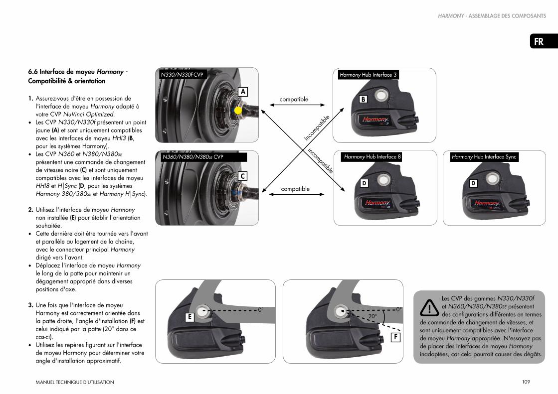
109
FR
MANUEL TECHNIQUE D’UTILISATION
E0° 0°
F
20°
B
DC
A
6.6 Interface de moyeu Harmony -Compatibilité & orientationpatibility & Orientation1. Assurez-vous d'être en possession de
l'interface de moyeu Harmony adapté à votre CVP NuVinci Optimized.
• Les CVP N330/N330f présentent un point jaune (A) et sont uniquement compatibles avec les interfaces de moyeu HHI3 (B, pour les systèmes Harmony).
• Les CVP N360 et N380/N380SE présentent une commande de changement de vitesses noire (C) et sont uniquement compatibles avec les interfaces de moyeu HHI8 et H|Sync (D, pour les systèmes Harmony 380/380SE et Harmony H|Sync).
2. Utilisez l'interface de moyeu Harmony non installée (E) pour établir l'orientation souhaitée.
• Cette dernière doit être tournée vers l'avant et parallèle au logement de la chaîne, avec le connecteur principal Harmony dirigé vers l'avant.
• Déplacez l'interface de moyeu Harmony le long de la patte pour maintenir un dégagement approprié dans diverses positions d'axe.
3. Une fois que l'interface de moyeu Harmony est correctement orientée dans la patte droite, l'angle d'installation (F) est celui indiqué par la patte (20° dans ce cas-ci).
• Utilisez les repères figurant sur l'interface de moyeu Harmony pour déterminer votre angle d'installation approximatif.
Les CVP des gammes N330/N330f et N360/N380/N380SE présentent des configurations différentes en termes
de commande de changement de vitesses, et sont uniquement compatibles avec l'interface de moyeu Harmony appropriée. N'essayez pas de placer des interfaces de moyeu Harmony inadaptées, car cela pourrait causer des dégâts.
compatible
compatible
incom
patib
le
D
incompatible
!
Harmony Hub Interface 3
Harmony Hub Interface 8 Harmony Hub Interface Sync
N330/N330f CVP
N360/N380/N380SE CVP
HARMONY - ASSEMBLAGE DES COMPOSANTS

110
FR
MANUEL TECHNIQUE D’UTILISATION
6.7 Installation de l'interface de moyeu Harmony
1. Enlevez le disque de retenue anti-glissement le cas échéant (voir section 6.2).
Les CVP des gammes N330/N330f et N360/N380/N380SE présentent des configurations différentes en
termes de commande de changement de vitesses et sont uniquement compatibles avec l'interface de moyeu Harmony appropriée (voir section 6.6).
La position de la commande de changement de vitesses ne revêt aucune importance durant
l'assemblage de produits Harmony ; la procédure de calibrage se chargera de déterminer automatiquement la position appropriée.
2. Suspendez l'interface de moyeu Harmony sur l'axe de droite et alignez les parties planes de l'axe (A) sur l'angle d'installation défini dans la section 6.6.
• Il est également possible de placer une rondelle fixe (B) sur l'interface de moyeu Harmony pour ajuster l'angle d'installation.
A
B
C
C
!
!
HARMONY - ASSEMBLAGE DES COMPOSANTS
3. Lorsque l'angle d'installation est aligné, enfilez entièrement l'interface de moyeu Harmony sur la commande de changement de vitesses et l'écrou de clavette jusqu'à ce qu'elle soit au même niveau que l'écrou.
4. Vissez l'écrou côté droit (C) sur l'axe, les dentelures vers l'extérieur, en appliquant un couple de serrage de 10-15 Nm (7-11 pi-lbs).
5. Installez la roue arrière conformément à la section 5.2.

111
FR
MANUEL TECHNIQUE D’UTILISATION
6.8 Installation du régulateur Harmony H8
1. Placez le levier de frein droit conformément aux indications du fabricant.
2. Glissez le régulateur H8 (A) sur le guidon.
3. Install the right hand grip (B) onto the handlebar according to the manufacturer’s instructions
4. Positionnez le régulateur de manière à ce que l'écran (C) soit visible pour le cycliste et le câble dégagé.
• Vissez le boulon de serrage selon un couple de 2,0-2,5 Nm (18-22 po-lbs).
N'utilisez jamais de lubrifiants ou de solvants pour installer les poignées du guidon.
Veillez au bon fonctionnement du régulateur et du levier de freinage et assurez-vous qu'ils ne sont pas
entravés (procédez à un réajustement le cas échéant).
Ne circulez jamais à vélo sans les poignées du guidon. La poignée rotative du dérailleur pourrait se
détacher, entraînant de graves blessures..
6.9 Installation du régulateur Harmony H3
1. Le régulateur H3 est monté sur une base en caoutchouc qui s'enroule autour d'un guidon standard, juste à côté de la poignée.
2. Employez le joint torique en caoutchouc fourni pour fixer le régulateur H3 et placez-le de façon à ce que l'écran soit visible pour le cycliste et le câble dégagé.
• Le régulateur H3 peut être installé tant sur le côté gauche que droit du guidon.
C
A
B
!
!
!
HARMONY - ASSEMBLAGE DES COMPOSANTS

112
FR
MANUEL TECHNIQUE D’UTILISATION
6.10 Harmony - Raccordements électriques
Vous trouverez ci-dessous un aperçu des raccordements électriquesdes systèmes Harmony 330 et Harmony 380/380SE :
Vous trouverez ci-dessous un aperçu des raccordements électriques du système Harmony H|Sync :
Câblage en Y – de l'interface de moyeu Harmony jusqu'à la zone de l'axe de pédalier (AP)
Câblage d'alimentation – de la batterie / du système d'alimentation du vélo électrique jusqu'à la zone de l'AP
Câble du régulateur du cycliste – du guidon à la zone de l'AP
Connexion à l'alimentation du vélo électrique (fourni par le fabricant de l'équipement d'origine)
Connexions Harmony (fournies)
18-44V
Câblage H|Sync – directement relié au système du vélo électrique pour l'alimentation et la communication CAN
Connexions H|Sync (fournies)
HARMONY - ASSEMBLAGE DES COMPOSANTS

113
FR
MANUEL TECHNIQUE D’UTILISATION
7. Harmony - Instructions pour l’entretien
7.1 Entretien ou remplacement de la roue libre
1. Enlevez la roue arrière conformément à la section 5.1.
2. Retirez l'interface de moyeu Harmony ainsi que le plateau de vitesse d'entrée Harmony en effectuant la procédure inverse à celle décrite dans la section 6.7 et la section 6.3.
3. Consultez la vue éclatée dans la section
8.3. Enlevez la bague de serrage du pignon (12), l'entretoise du pignon (13, le cas échéant) ainsi que le pignon lui-même (14).
4. Ôtez la bague de serrage (15) sur la commande de changement de vitesses et retirez l'assemblage de la roue libre (16).
5. Lors d'une réparation ou d'un remplacement, utilisez de l'huile de poids moyen ou de la graisse légère résistante à l'eau, et vérifiez le fonctionnement du cliquet ainsi que du ressort.
6. Enlevez la bague de serrage intérieure (17), le roulement à aiguilles (18) et la protection côté droit (19) si ces composants doivent être remplacés.
HARMONY - INSTRUCTIONS DE SERVICE
7. Installez les nouveaux composants / les composants réparés conformément à la vue éclatée présentée dans la section 5.3.
8. Placez le pignon et les composants Harmony en respectant les étapes 2 et 3 décrites ci-dessus.
9. Installez la roue arrière conformément à la section 5.2.
1918171615
15
18
19
15
16

114
FR
MANUEL TECHNIQUE D’UTILISATION
7.2 Démontage des freins
Consultez la vue éclatée dans la section 8.3 pour la numérotation et les descriptions.
Enlevez la roue arrière tel que décrit dans la section 5.1.
Démontage du matériel d'un frein à rouleau
1. Enlevez l'écrou d'axe gauche (1), la rondelle fixe gauche (2) et l'écrou gauche (3).
2. Bloquez la roue et utilisez l'outil d'entretien N360T-BKAD-01 pour retirer le jonc d'arrêt du frein (6), puis enlevez l'adaptateur du frein à rouleau (7) du CVP.
Démontage du matériel d'un frein sur jante
1. Enlevez l'écrou d'axe gauche (1), la rondelle fixe gauche (2), l'écrou gauche (3) et la rondelle bombée (4).
2. À l'aide d'un instrument mince et plat, soulevez, puis retirez le couvercle du frein sur jante (5).
!
Démontage du matériel d'un frein à disque
1. Enlevez l'écrou d'axe gauche (1), la rondelle fixe gauche (2), l'écrou gauche (3) et la rondelle bombée (4).
2. Bloquez la roue et utilisez l'outil d'entretien
N360T-BKAD-01 pour retirer le jonc d'arrêt du frein (6), puis ôtez la protection du frein (8) et l'adaptateur du frein à rouleau (9) du CVP.
HARMONY - INSTRUCTIONS DE SERVICE

115
FR
MANUEL TECHNIQUE D’UTILISATION
!
7.3 Montage des freins
Consultez la vue éclatée dans la section 8.3 pour la numérotation et les descriptions.
Montage du matériel d'un frein à rouleau
1. Installez l'adaptateur du frein à rouleau (7) et appliquez un produit de freinage haute résistance pour fixations filetées (équivalent au Loctite® 277™) sur un tour de filetage complet du jonc d'arrêt du frein (6).
2. À l'aide de l'outil d'entretien N360T-BKAD-01, placez le jonc d'arrêt du frein (6) et serrez-le selon un couple de 55-65 Nm (41-48 pi-lbs).
3. Après avoir installé le frein à rouleau, disposez l'écrou gauche (3) et serrez-le selon un couple de 30-35 Nm (22-26 pi-lbs).
Montage du matériel d'un frein sur jante
1. Une fois que le couvercle du frein sur jante (5) est dans la bonne position, appuyez dessus jusqu'à ce qu'il s'intègre parfaitement, puis procédez de même avec la rondelle bombée (4).
2. Disposez l'écrou gauche (3) et serrez-le selon un couple de 30-35 Nm (22-26 pi-lbs).
HARMONY - INSTRUCTIONS DE SERVICE
Montage du matériel d'un frein à disque
1. Installez l'adaptateur du frein à disque (9) et la protection du frein (8), puis appliquez un produit de freinage haute résistance pour fixations filetées (équivalent au Loctite® 277™) sur un tour de filetage complet du jonc d'arrêt du frein (6).
2. À l'aide de l'outil d'entretien N360T-
BKAD-01, placez le jonc d'arrêt du frein (6) et serrez-le selon un couple de 55-65 Nm (41-48 pi-lbs).
3. Disposez l'écrou gauche (3) et serrez-le selon un couple de 30-35 Nm (22-26 pi-lbs).

116
FR
MANUEL TECHNIQUE D’UTILISATION
8. Harmony - Données techniques
HARMONY - DONNÉES TECHNIQUES
8.1 Spécifications du CVP
*Les interfaces de moyeu Harmony MY12-15 sont uniquement compatibles avec une chaîne.
**Ces données font référence à toutes les interfaces de moyeu Harmony MY12-15 uniquement compatibles avec une chaîne.
Harmony 330
Moyeu N380/380SE
Couleur du moyeu Argenté ou noir
Rapport de vitesse À variation continue au sein de la plage de rapports
Plage de rapports 380% de valeur nominale, de 0,5 en
sous-multiplication à 1,9 en surmultiplication
Régulateur H8
Autre régulateur compatible H|Sync
Changement de vitesses Poignée rotative variable, ¾ tour
Interface de moyeu HHI8
Autres IM compatibles H|SYNC, (interfaces de moyeu Harmony MY12-15)*
Types de rayon À 32 ou 36 orifices
Type de freins À disque, sur jante ou à rouleau
Largeur de la patte 135 mm, horizontal ou vertical
Longueur de l'axe 183 mm
Filetages de l'axe M10 x 1
Chaîne 49,0 ± 0,5 mm
Courroie (Gates) 45,5 ± 0,5 mm
Courroie (Conti-Tech) 46,2 ± 0,5 mm
Tailles de pignons 16-20 dents (chaîne)
16-22 dents (chaîne)**
20-28 dents (courroie)
Type de pignon Standard à 9 clavettes, plat d'un côté
Définition du rapport de pignon Dents de pignon avant / Dents de pignon arrière
Rapport de pignon min.(vélos à pédales) 1,8 (tableau dans la section 8.2)
Rapport de pignon min. (vélos électriques avec moteur à l'avant) 1,8 (tableau dans la section 8.2)
Rapport de pignon min. (vélos électriques avec moteur intermédiaire) 2,1 (tableau dans la section 8.2)
Diamètre de la flasque 125,0 mm
Distance du centre à l'extrémité gauche de la flasque 26,0 mm
Distance du centre à l'extrémité droite de la flasque 26,0 mm
Harmony 380/380SE
Moyeu N330/N330f
Couleur du moyeu Argenté ou noir
Rapport de vitesse À variation continue au sein de la plage de rapports
Plage de rapports 330 % de valeur nominale, de 0,5 en
sous-multiplication à 1,65 en surmultiplication
Régulateur H3
Autre régulateur compatible –
Changement de vitesses Poignée rotative variable, ¾ tour
Interface de moyeu HHI3
Autres IM compatibles –
Types de rayon À 32 ou 36 orifices
Type de freins À disque, sur jante ou à rouleau
Largeur de la patte 135 mm, horizontal ou vertical
Longueur de l'axe 183 mm Filetages de l'axe M10 x 1
Chaîne 49,0 ± 0,5 mm
Courroie (Gates) 45,5 ± 0,5 mm
Courroie (Conti-Tech) 46,2 ± 0,5 mm
Tailles de pignons 16-22 dents (chaîne)
20-28 dents (courroie)
Type de pignon Standard à 9 clavettes, plat d'un côté
Définition du rapport de pignon Dents de pignon avant / Dents de pignon arrière
Rapport de pignon min. (vélos à pédales) 1,8 (tableau dans la section 8.2)
Rapport de pignon min.(vélos électriques avec moteur à l'avant) 1,8 (tableau dans la section 8.2)
Rapport de pignon min. (vélos électriques avec moteur intermédiaire) 2,1 (tableau dans la section 8.2)
Diamètre de la flasque 125,0 mm
Distance du centre à l'extrémité gauche de la flasque 26,0 mm
Distance du centre à l'extrémité droite de la flasque 26,0 mm

117
FR
HARMONY - DONNÉES TECHNIQUES
117
8.2 Engrenages autorisés
- Rapport de pignon minimum de 2,0 pour les vélos électriques avec moteur pédalier de 350 W ou moins
- Rapport de pignon minimum de 1,8 pour tous les vélos à pédales et vélos électriques avec moteur à l‘avant
- Rapport de pignon minimum de 0,8 pour tous les vélos électriques avec Bosch GEN2 de 350 W ou moins
58 & superiéur
56
54
52
50
48
46
44
42
40
39
38
36
34
33
32
30
28
27 & inférieur
N330 CVP pignons autorisés (Nfinity 330, Nfinity 330f & Harmony 330 groupe de produits) N380 CVP pignons autorisés (Nfinity 380, Nfinity 380SE, Harmony 380/380SE, and Harmony HISync groupe de produits)
Plat
eau
de c
haîn
e av
ant /
pig
non
24 & superiéur
23
22
21
20
19
18
17
16
15
14
13 & inférieur
Pign
on a
vant
Bos
ch G
EN2
16 17 18 19 20 21 22 23 24 26 28 16 17 18 19 20 21 22 23 24 26 28
Autorisé pour n‘importe quel vélo (y compris les vélos électriques avec moteur pédalier de 250 W) Autorisé pour n‘importe quel vélo (y compris les vélos électriques avec moteur pédalier de 350 W)
N330 CVP (Nfinity 330, Nfinity 330f & Harmony 330 groupe de produits) N380 CVP (Nfinity 380, Nfinity 380SE, Harmony 380/380SE & Harmony HISync groupe de produits)
Rapport de pignon = plateau de chaîne avant / pignon arrière Rapport de pignon = plateau de chaîne avant / pignon arrière
Non autorisé quel que soit le type de vélo Non autorisé quel que soit le type de vélo
Les systèmes Nfinity 330; Nfinity 330f et Harmony 330 sont jumelés avec
le N330 CVP et sont compatibles avec les vélos électriques avec moteur pédalier de 250 W ou moins, avec les pignons autorisés comme indiqué dans le tableau associé au N330 sur cette page.
Les systèmes Nfinity 380, Nfinity 380SE et Harmony 380/380SE sont jumelés
avec le N380 CVP et sont compatibles avec les vélos électriques avec moteur pédalier de 350 W ou moins, avec les pignons autorisés comme indiqué dans le tableau associé au N380 sur cette page.
! !Autorisé pour les vélos et vélos électriques dotés d‘un moteur sur le moyeu avant(non autorisé pour les vélos électriques avec moteur pédalier)
Autorisé pour les vélos et vélos électriques dotés d‘un moteur sur le moyeu avant(non autorisé pour les vélos électriques avec moteur pédalier)
3,6 3,4 3,2 3,1 2,9 2,8 2,6 2,5 2,4 2,2 2,1
3,5 3,3 3,1 2,9 2,8 2,7 2,5 2,4 2,3 2,2 2,0
3,4 3,2 3,0 2,8 2,7 2,6 2,5 2,3 2,3 2,1 1,9
3,3 3,1 2,9 2,7 2,6 2,5 2,4 2,3 2,2 2,0 1,9
3,1 2,9 2,8 2,6 2,5 2,4 2,3 2,2 2,1 1,9 1,8
3,0 2,8 2,7 2,5 2,4 2,3 2,2 2,1 2,0 1,8 1,7
2,9 2,7 2,6 2,4 2,3 2,2 2,1 2,0 1,9 1,8 1,6
2,8 2,6 2,4 2,3 2,2 2,1 2,0 1,9 1,8 1,7 1,6
2,6 2,5 2,3 2,2 2,1 2,0 1,9 1,8 1,8 1,6 1,5
2,5 2,4 2,2 2,1 2,0 1,9 1,8 1,7 1,7 1,5 1,4
2,4 2,3 2,2 2,1 2,0 1,9 1,8 1,7 1,6 1,5 1,4
2,4 2,2 2,1 2,0 1,9 1,8 1,7 1,7 1,6 1,5 1,4
2,3 2,1 2,0 1,9 1,8 1,7 1,6 1,6 1,5 1,4 1,3
2,1 2,0 1,9 1,8 1,7 1,6 1,5 1,5 1,4 1,3 1,2
2,1 1,9 1,8 1,7 1,7 1,6 1,5 1,4 1,4 1,3 1,2
2,0 1,9 1,8 1,7 1,6 1,5 1,5 1,4 1,3 1,2 1,1
1,9 1,8 1,7 1,6 1,5 1,4 1,4 1,3 1,3 1,2 1,1
1,8 1,6 1,6 1,5 1,4 1,3 1,3 1,2 1,2 1,1 1,0
1,7 1,6 1,5 1,4 1,4 1,3 1,2 1,2 1,1 1,0 1,0
1,50 1,41 1,33 1,26 1,20 1,14 1,09 1,04 1,00 0,92 0,86
1,44 1,35 1,28 1,21 1,15 1,10 1,05 1,00 0,96 0,88 0,82
1,38 1,29 1,22 1,16 1,10 1,05 1,00 0,96 0,92 0,85 0,79
1,31 1,24 1,17 1,11 1,05 1,00 0,95 0,91 0,88 0,81 0,75
1,25 1,18 1,11 1,05 1,00 0,95 0,91 0,87 0,83 0,77 0,71
1,19 1,12 1,06 1,00 0,95 0,90 0,86 0,83 0,79 0,73 0,68
1,13 1,06 1,00 0,95 0,90 0,86 0,82 0,78 0,75 0,69 0,64
1,06 1,00 0,94 0,89 0,85 0,81 0,77 0,74 0,71 0,65 0,61
1,00 0,94 0,89 0,84 0,80 0,76 0,73 0,70 0,67 0,62 0,57
0,94 0,88 0,83 0,79 0,75 0,71 0,68 0,65 0,63 0,58 0,54
0,88 0,82 0,78 0,74 0,70 0,67 0,64 0,61 0,58 0,54 0,50
0,81 0,76 0,72 0,68 0,65 0,62 0,59 0,57 0,54 0,50 0,46
3,6 3,4 3,2 3,1 2,9 2,8 2,6 2,5 2,4 2,2 2,1
3,5 3,3 3,1 2,9 2,8 2,7 2,5 2,4 2,3 2,2 2,0
3,4 3,2 3,0 2,8 2,7 2,6 2,5 2,3 2,3 2,1 1,9
3,3 3,1 2,9 2,7 2,6 2,5 2,4 2,3 2,2 2,0 1,9
3,1 2,9 2,8 2,6 2,5 2,4 2,3 2,2 2,1 1,9 1,8
3,0 2,8 2,7 2,5 2,4 2,3 2,2 2,1 2,0 1,8 1,7
2,9 2,7 2,6 2,4 2,3 2,2 2,1 2,0 1,9 1,8 1,6
2,8 2,6 2,4 2,3 2,2 2,1 2,0 1,9 1,8 1,7 1,6
2,6 2,5 2,3 2,2 2,1 2,0 1,9 1,8 1,8 1,6 1,5
2,5 2,4 2,2 2,1 2,0 1,9 1,8 1,7 1,7 1,5 1,4
2,4 2,3 2,2 2,1 2,0 1,9 1,8 1,7 1,6 1,5 1,4
2,4 2,2 2,1 2,0 1,9 1,8 1,7 1,7 1,6 1,5 1,4
2,3 2,1 2,0 1,9 1,8 1,7 1,6 1,6 1,5 1,4 1,3
2,1 2,0 1,9 1,8 1,7 1,6 1,5 1,5 1,4 1,3 1,2
2,1 1,9 1,8 1,7 1,7 1,6 1,5 1,4 1,4 1,3 1,2
2,0 1,9 1,8 1,7 1,6 1,5 1,5 1,4 1,3 1,2 1,1
1,9 1,8 1,7 1,6 1,5 1,4 1,4 1,3 1,3 1,2 1,1
1,8 1,6 1,6 1,5 1,4 1,3 1,3 1,2 1,2 1,1 1,0
1,7 1,6 1,5 1,4 1,4 1,3 1,2 1,2 1,1 1,0 1,0
58 & superiéur
56
54
52
50
48
46
44
42
40
39
38
36
34
33
32
30
28
27 & inférieur
Plat
eau
de c
haîn
e av
ant /
pig
non
24 & superiéur
23
22
21
20
19
18
17
16
15
14
13 & inférieur
Pign
on a
vant
Bos
ch G
EN2
- Rapport de pignon minimum de 2,1 pour les vélos électriques avec moteur pédalier de 250 W ou moins
- Rapport de pignon minimum de 1,8 pour tous les vélos à pédales et vélos électriques avec moteur à l‘avant
- Rapport de pignon minimum de 0,84 pour tous les vélos électriques avec Bosch GEN2 de 250 W ou moins
1,50 1,41 1,33 1,26 1,20 1,14 1,09 1,04 1,00 0,92 0,86
1,44 1,35 1,28 1,21 1,15 1,10 1,05 1,00 0,96 0,88 0,82
1,38 1,29 1,22 1,16 1,10 1,05 1,00 0,96 0,92 0,85 0,79
1,31 1,24 1,17 1,11 1,05 1,00 0,95 0,91 0,88 0,81 0,75
1,25 1,18 1,11 1,05 1,00 0,95 0,91 0,87 0,83 0,77 0,71
1,19 1,12 1,06 1,00 0,95 0,90 0,86 0,83 0,79 0,73 0,68
1,13 1,06 1,00 0,95 0,90 0,86 0,82 0,78 0,75 0,69 0,64
1,06 1,00 0,94 0,89 0,85 0,81 0,77 0,74 0,71 0,65 0,61
1,00 0,94 0,89 0,84 0,80 0,76 0,73 0,70 0,67 0,62 0,57
0,94 0,88 0,83 0,79 0,75 0,71 0,68 0,65 0,63 0,58 0,54
0,88 0,82 0,78 0,74 0,70 0,67 0,64 0,61 0,58 0,54 0,50
0,81 0,76 0,72 0,68 0,65 0,62 0,59 0,57 0,54 0,50 0,46
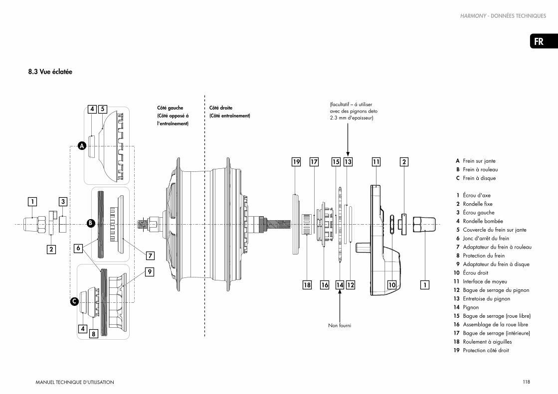
118
FR
MANUEL TECHNIQUE D’UTILISATION
8.3 Vue éclatée
18 16 14 12 10
19 17 15 13 11 2 Frein sur jante
Frein à rouleau
Frein à disque
Écrou d'axe
Rondelle fixe
Écrou gauche
Rondelle bombée
Couvercle du frein sur jante
Jonc d'arrêt du frein
Adaptateur du frein à rouleau
Protection du frein
Adaptateur du frein à disque
Écrou droit
Interface de moyeu
Bague de serrage du pignon
Entretoise du pignon
Pignon
Bague de serrage (roue libre)
Assemblage de la roue libre
Bague de serrage (intérieure)
Roulement à aiguilles
Protection côté droit
A
B
C
1
2
3
4
5
6
7
8
9
10
11
12
13
14
15
16
17
18
19
7
9
48
6
4 5
1
2
3
A
B
C
(facultatif – á utiliser avec des pignons deto 2.3 mm d'epaisseur)
Non fourni
Côté gauche
(Côté opposé á
l'entraînement)
Côté droite
(Côté entraînement)
1
HARMONY - DONNÉES TECHNIQUES

119
FR
MANUEL TECHNIQUE D’UTILISATION
8.4 Dimensions du CVP et du dérailleur Harmony
Régulateur H3 Régulateur H8
CVP avec interface de moyeu Harmony CVP avec interface de moyeu Harmony Interface de moyeu Harmony
12532 AND 36 SPOKECONFIGURATIONS
AVAILABLE
2.9SPOKEHOLE
SCALE 0.500
SCALE 0.500
183 AXLE WIDTH
135 DROPOUT WIDTH
VERSIONDISC BRAKE
ISO 6 BOLT16.0
41
73
67.5CENTERLINE
49.0CHAINLINE
26.026.0
MULTI-GEAR(2.3MM OR 3/32")CHAINS ANDSPROCKETS ONLY
HARMONY - DONNÉES TECHNIQUES
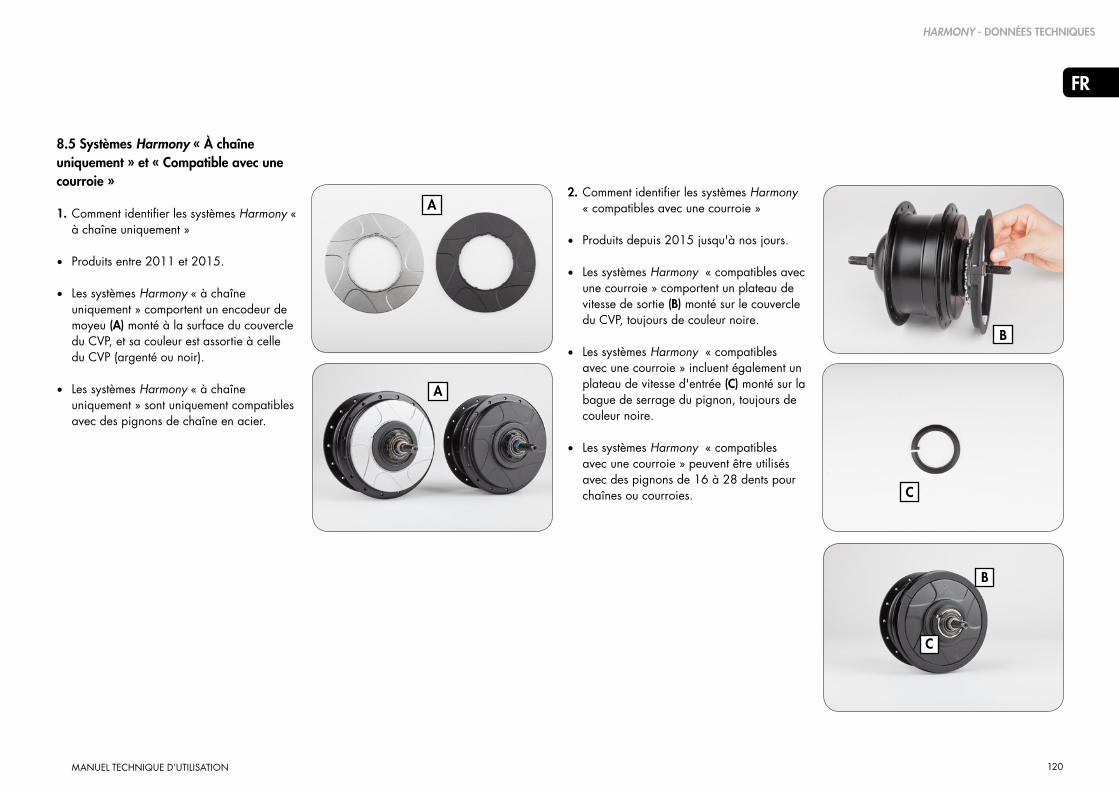
120
FR
MANUEL TECHNIQUE D’UTILISATION
8.5 Systèmes Harmony « À chaîne uniquement » et « Compatible avec une courroie »
1. Comment identifier les systèmes Harmony « à chaîne uniquement »
• Produits entre 2011 et 2015.
• Les systèmes Harmony « à chaîne uniquement » comportent un encodeur de moyeu (A) monté à la surface du couvercle du CVP, et sa couleur est assortie à celle du CVP (argenté ou noir).
• Les systèmes Harmony « à chaîne uniquement » sont uniquement compatibles avec des pignons de chaîne en acier.
A
B
C
A
B
C
2. Comment identifier les systèmes Harmony « compatibles avec une courroie »
• Produits depuis 2015 jusqu'à nos jours.
• Les systèmes Harmony « compatibles avec une courroie » comportent un plateau de vitesse de sortie (B) monté sur le couvercle du CVP, toujours de couleur noire.
• Les systèmes Harmony « compatibles avec une courroie » incluent également un plateau de vitesse d'entrée (C) monté sur la bague de serrage du pignon, toujours de couleur noire.
• Les systèmes Harmony « compatibles avec une courroie » peuvent être utilisés avec des pignons de 16 à 28 dents pour chaînes ou courroies.
HARMONY - DONNÉES TECHNIQUES

121
FR
MANUEL TECHNIQUE D’UTILISATION
AVIS DE PROPRIÉTÉ INTELLECTUELLE
9. Droits de propriété intellectuelle
Les unités de commande NuVinci Optimized N360, Harmony& Harmony H|Sync
Droits de propriété intellectuelle
En achetant et/ou en utilisant ces composants NuVinci Optimized et/ou le vélo qui les intègre, vous acceptez les conditions générales ci-dessous. Si vous ne souhaitez pas être soumis à ces conditions générales, vous devez rapporter les composants NuVinci Optimized dans un délai de trois (3) jours pour obtenir un remboursement intégral. Les composants NuVinci Optimized vendus doivent être utilisés exclusivement sur la roue arrière d'un vélo, dans l'optique d'une application sur le moyeu arrière conforme à l'usage courant et aux instructions qui les accompagnent. Vous consentez à ne pas employer les composants NuVinci Optimized pour toute autre fin, y compris la rétro-ingénierie ou la reproduction, sans toutefois s'y limiter. Toute utilisation non autorisée des composants NuVinci Optimized est déconseillée, entraînera l'annulation de toutes les garanties applicables et, dans la mesure où cette utilisation inappropriée aboutirait à des améliorations ou inventions basées sur
ces composants, en vertu de la législation en vigueur, Fallbrook Technologies Inc. et ses titulaires de permis bénéficieront d'une licence exempte de redevance, permanente et non exclusive valable dans le monde entier pour la totalité des droits découlant de telles inventions et améliorations.
Les composants NuVinci Optimized vendus comprenant notamment le moyeu arrière, le régulateur et le dérailleur sans toutefois s'y limiter, sont protégés par les brevets américains 7,871,353 ; 7,885,747 ; 7,959,533 ; 8,321,097 ; 8,376,903 ; 8,398,518 ; 8,506,452 ; 8,626,409 ; les brevets européens EP2171312 ; EP2234869 ; le brevet danois 1954959 ; le brevet espagnol ES2424652 ; ainsi que par d’autres brevets étrangers. Des demandes de brevets américains et étrangers supplémentaires sont en cours pour Fallbrook Technologies Inc. et sa filiale Fallbrook Intellectual Property Co. LLC.Les produits Harmony et H|Sync
comprennent également des logiciels, des microprogrammes ou d’autres informations numériques (appelés conjointement le « Logiciel ») qui peuvent être embarqués ou sont disponibles auprès de Fallbrook Technologies ou de leurs représentants autorisés pour l’utilisation des produits.
Le Logiciel est protégé par le droit d’auteur dans chaque juridiction ou pays et toute reproduction, représentation, utilisation, publication ou modification non autorisée est interdite.
Fallbrook, NuVinci, N360, Harmony, Harmony H|Sync et leurs logos stylisés et éléments associés sont des marques commerciales ou marques déposées de Fallbrook Technologies Inc.Bosch et Intuvia sont des marques commerciales de Robert Bosch GmbH.Tous droits réservés. © 2015

122
FR
MANUEL TECHNIQUE D’UTILISATION
GARANTIE
10. Garantie
LA PRÉSENTE GARANTIE FACULTATIVE DE DEUX ANS EST PROPOSÉE PAR LA SOCIÉTÉ FALLBROOK TECHNOLOGIES INC. (CI-APRÈS : « FALLBROOK ») ET EST VALABLE POUR LES PRODUITS SUIVANTS : NUVINCI OPTIMIZED, N330, N330f, N360, N380, N380SE, C3, C8, C8S, H3, H8, NFINITY 330, NFINITY 330f, NFINITY 380, NFINITY 380SE, HARMONY 330, HARMONY 380, HARMONY 380SE, HARMONY H|SYNC, NFINITY HI, HHI3, HHI8, HHISYNC (CI-APRÈS : « LES PRODUITS FALLBROOK »).
CONFORMÉMENT À LA LÉGISLATION DE CERTAINS PAYS (P.EX. L'ALLEMAGNE, LES PAYS-BAS), LES ACHETEURS DISPOSENT DE DROITS DE GARANTIE LÉGAUX EN CAS DE PRODUITS DÉFECTUEUX OU NE CORRESPONDANT PAS AU CONTRAT DE VENTE. CES DROITS AUTORISENT L'ACHETEUR À EXIGER DU VENDEUR UNE RÉPARATION GRATUITE, UN REMPLACEMENT OU, SOUS CERTAINES CONDITIONS, UNE RÉDUCTION DU PRIX D'ACHAT OU UN REMBOURSEMENT DU PRIX D'ACHAT. LA PRÉSENTE GARANTIE FACULTATIVE NE PORTE PAS ATTEINTE À VOS DROITS DE GARANTIE LÉGAUX. SI, LORS DE L'ACHAT DE PRODUITS FALLBROOK, VOUS RÉSIDEZ DANS L'UN DE CES PAYS, LES DROITS DÉCRITS CI-DESSOUS DE LA GARANTIE DE FALLBROOK S'AJOUTENT À VOS DROITS DE GARANTIE LÉGAUX. CES DROITS EXISTENT PARALLÈLEMENT À VOS DROITS DE GARANTIE LÉGAUX, DE FAÇON À CE QUE VOUS PUISSIEZ CHOISIR ENTRE VOS DROITS DE GARANTIE LÉGAUX ET VOS DROITS DÉCOULANT DE LA GARANTIE LIMITÉE DE FALLBROOK DANS LE CAS OÙ VOTRE PRODUIT FALLBROOK S'AVÉRERAIT ÊTRE DÉFECTUEUX PENDANT LA PÉRIODE DE GARANTIE OU QU'IL NE CORRESPONDRAIT PAS AU CONTRAT DE VENTE.
Que couvre la présente garantie ?
Fallbrook Technologies Inc. (Fallbrook) assume une garantie pour tous les produits Fallbrook présentant des défauts de matériel ou de fabrication. Cette garantie concerne uniquement l'acheteur d'origine et n'est pas transmissible. (Certains États ou pays n'autorisent pas une restriction de la garantie à l'acheteur d'origine, c'est pourquoi il est possible que cette limitation ne s'applique pas à vous). Si vous avait fait l'acquisition de votre produit Fallbrook en tant que partie d'un autre produit, la présente garantie ne remplace en aucune manière la garantie ou sécurité du fabricant de ce produit et n'en étend pas la portée, car toute garantie ou sécurité relève de la responsabilité du seul fabricant.
Combien de temps la garantie est-elle valable ?
La garantie est valable pour deux ans à compter de la date de l'achat original.
Que mettra en œuvre Fallbrook ?
Fallbrook décidera à sa seule discrétion si l'unité défectueuse doit être réparée, remplacée ou si le prix d'achat doit être remboursé.
Qu'est ce qui n'est pas couvert par la garantie ?
La garantie ne couvre pas ce qui suit :
• La détérioration normale des éléments constitutifs causée par l'usure normale, comme par exemple l'usure des joints et anneaux en caoutchouc, rouleaux des tendeurs de chaînes (le cas échéant), caoutchouc des poignées et câbles des vitesses.
• Dommages aux éléments (comme par exemple les pattes de dérailleur et chaînes) qui n'ont pas été fabriqués par Fallbrook ou par des entreprises liées à Fallbrook (au sens de l'article 15 AktG).
• Les travaux nécessaires pour remonter ou adapter le produit dans le vélo.
• Un produit monté dans un autre produit qui n'est pas, par définition, un vélo. Les tandems ne sont pas couverts.
• Un produit qui n'a pas été monté correctement et/ou en respectant les instructions du manuel technique de montage des groupes de produits Nfinity ou Harmony. Ceux-ci sont disponibles en suivant ce lien http://www.nuvincicycling.com/en/service/downloads.html.
• Un produit qui a été démonté au-delà de la mesure prévue dans les manuels techniques (groupes de produits NuVinci Optimized Harmony ou Nfinity).

123
FR
MANUEL TECHNIQUE D’UTILISATION
GARANTIE
• Un produit ayant subi une modification ou dont le numéro de série ou le code de date a été modifié, créé ou enlevé.
• Un autre produit que le N330f utilisé à des fins commerciales sans pré-autorisation écrite de Fallbook. Seul N330f peut être utilisé à des fins commerciales raisonnables et cette garantie sera limitée à un (1) an pour une telle utilisation commerciale raisonnable.
• Les dommages sur le produit : - qui, selon l'évaluation de Fallbrook, ont été causés par un impact, une chute ou une mauvaise manipulation du produit - qui, dans l'opinion de Fallbrook, ont été causés par une utilisation dans des milieux extrêmes (par exemples les styles « descente », « freeride », « North Shore » et BMX) - qui ont été causés par l'opération du produit avec des moteurs électriques de plus de 250 watts pour les modèles N330/N330f/N360 et de plus de 350 watts pour les modèles N380/N380SE, ou par toute utilisation avec un moteur à combustion interne ;
- qui ont été causés par l'utilisation de moteurs électriques avec un couple nominal supérieur à 80 Nm ou un couple maximum supérieur à 90 Nm ; - qui ont été causés par l'utilisation du produit avec un poids total (cycliste, charge et vélo) de plus de 200 kg ; - qui ont été causés par l'utilisation du produit en-dehors des rapports de vitesses prescrits de 1,8 pour 1 pour les vélos standards et de 2,1 pour 1 (N330/N330f) et de 2,0 pour 1 (N360/N380/N380SE) pour les eBikes ; - qui ont été causés par l'utilisation du produit avec des tensions supérieures à 50 V - qui ont été causés par l'utilisation de pièces non-compatibles, adaptées et/ou autorisées à être utilisées avec le produit par Fallbrook ; - qui sont survenus pendant le transport du produit.
Comment obtenir des prestations dans le cadre de la garantie ?
Les recours à la présente garantie doivent être déposés chez le détaillant où le vélo ou la pièce NuVinci Optimized a été acheté ou auprès d'un détaillant de produits NuVinci Optimized. Veuillez retourner le produit avec la facture originale datée ou la quittance chez le détaillant. Le détaillant prend contact avec le service clientèle de NuVinci Cycling pour traiter votre recours à la garantie. Les détaillants souhaitant recourir à la garantie sont priés de s'adresser au service clientèle de NuVinci Cycling afin d'obtenir une autorisation de prestation de garantie. Le détaillant doit ensuite renvoyer le produit à NuVinci Cycling avec une preuve suffisante de la date d'achat.

124
FR
MANUEL TECHNIQUE D’UTILISATION
Limitations de la prestation de garantie
LA PRÉSENTE GARANTIE LIMITÉE EST LA GARANTIE UNIQUE ET EXCLUSIVE, DONNÉE PAR FALLBROOK SUR LE PRODUIT ET EN LIEU ET PLACE D'UNE ÉVENTUELLE AUTRE GARANTIE. DANS LE CADRE DE LA LÉGISLATION EN VIGUEUR, TOUTES LES AUTRES GARANTIES EXPLICITES OU IMPLICITES N'ÉTANT PAS MENTIONNÉES SONT EXCLUES PAR LA PRÉSENTE, Y COMPRIS LES ÉVENTUELLES GARANTIES IMPLICITES D'APTITUDE À L'EMPLOI OU D'ADÉQUATION POUR UN USAGE PARTICULIER. LA RESPONSABILITÉ DE FALLBROOK DANS LE CADRE DE LA GARANTIE LIMITÉE SE LIMITE EXCLUSIVEMENT AUX RESPONSABILITÉS DÉTAILLÉES CI-DESSUS. AU CAS OÙ L'UNE DES DISPOSITIONS DE LA PRÉSENTE GARANTIE LIMITÉE DEVAIT ÊTRE OU DEVENIR NULLE OU NON-APPLICABLE DANS LE CADRE DE LA LÉGISLATION EN VIGUEUR, LA VALIDITÉ DES AUTRES DISPOSITIONS DEMEURERAIT INTACTE ET LA DISPOSITION NULLE OU NON-APPLICABLE DEVRAIT ÊTRE MODIFIÉE DE FAÇON À ÊTRE RENDUE VALIDE ET APPLICABLE.
Fallbrook se réserve le droit de modifier la présente garantie limitée sans avertissement préalable.
GARANTIE
NuVinci CYCLINGBureau nord-américain
Fallbrook Technologies Inc.Cedar Park, Texas 78613 USA
USA toll free: 1-888-NuVinci (688-4624)
Tel: +1 (512) 279-6200 Fax: +1 (512) 267-0159
NuVinci CYCLINGService après-vente en Europe
Fallbrook Technologies InternationalPopovstraat 128013 RK Zwolle, The Netherlands
Allemagne et en Autriche+49 2289 2939 [email protected]
Suisse+41 43 508 55 [email protected]
Support Général Europe+31 38 7200 [email protected]

125
EN
TECHNICAL OWNER MANUAL
MANUAL TÉCNICO DE USO
CVP NUVINCI OPTIMIZED™ CON EL SISTEMA DE CAMBIOS AUTOMÁTICO HARMONY
MANU-HRMY-00
EN
DE32-62
1-31
63-93
94-124
NL
FR
125-155 ES

126
ES
MANUAL TÉCNICO DE USO
Tabla de contenidos
1. Productos NuVinci Cycling 127
1.1 Transmisiones inteligentes Harmony 330TM,
Harmony 380TM, Harmony 380SETM, y
Harmony H|SyncTM 127
1.2 The NuVinci OptimizedTM CVP 127
2. Funcionamiento y cuidado de Harmony 330 128
2.1 Sistema Harmony 330 128
2.2 Calibración del sistema Harmony 330 128
2.3 Actualización del sistema Harmony 330 128
3. Funcionamiento y cuidado del Harmony 380 129
3.1 Sistema Harmony 380/380SE 129
3.2 Calibración del sistema Harmony 380/380SE 129
4. Funcionamiento y cuidado del Harmony H|SYNC 130
4.1 Sistema Harmony H|Sync 130
4.2 Calibración de Harmony H|Sync Sistema
- General 130
4.3 Calibración del Harmony H|Sync Sistema
- Bosch Intuvia 131
5. Cuidado general de Harmony 132
5.1 Desconexión de la rueda trasera 132
5.2 Colocación de la rueda trasera 133
5.3 Limpieza y lubricación 134
5.4 Piezas de desgaste y trabajo de reparación 134
6. Montaje de los componentes de Harmony 135
6.1 Montaje de la rueda 135
6.2 Instalación del piñón 136
6.3 Instalación del anillo de velocidad de entrada 137
6.4 Instalación del anillo de velocidad de salida 138
6.5 Instalación del codificador del cojinete
(Antiguos sistemas Harmony) 139
6.6 Interfaz del cojinete Harmony
Compatibilidad y orientación 140
6.7 Instalación de la interfaz del cojinete Harmony 141
6.8 Instalación del controlador Harmony H8™ 142
6.9 Instalación del controlador Harmony H3™ 142
6.10 Conexiones eléctricas de Harmony 143
7. Instrucciones de servicio Harmony 144
7.1 Mantenimiento o repuesto de la rueda libre 144
7.2 Desmontar las configuraciones de los frenos 145
7.3 Instalar las configuraciones del freno 146
8. Datos técnicos Harmony 147
8.1 Especificaciones CVP 147
8.2 Engranajes aprobados 148
8.3 Vista detallada 149
8.4 Dimensiones de la CVP y de la palanca
de cambio Harmony 150
8.5 Sistemas Harmony «solo cadena» y
«compatible con correa» 151
9. Aviso de propiedad intelectual 152
10. Garantía 153
Soporte y servicio europeo 155
Oficina norteamericana 155

127
ES
MANUAL TÉCNICO DE USO
1.1 Transmisiones inteligentes Harmony 330, Harmony 380/380SE y Harmony H|Sync
La serie Harmony de sistemas de transmisiones inteligentes dispone de los primeros sistemas automáticos de cambio de velocidades de variación continua para bicicletas.
El sistema Harmony 330 ofrece un cambio de velocidades exclusivamente automático para la CVP NuVinci Optimized N330/N330f.
El sistema Harmony 380/380SE dispone tanto de opciones de control automáticas como manuales para las series de CVP NuVinci Optimized N360 y N380/N380SE.
El sistema Harmony H|Sync está completamente integrado en los principales sistemas de transmisión de bicicletas eléctricas, utiliza la interfaz de usuario de la bicicleta eléctrica y permite la máxima interacción entre la bicicleta y las series de CVP NuVinci Optimized N360 y N380/N380SE.
1. Productos NuVinci Cycling
1.2 La CVP NuVinci Optimized
La tecnología NuVinci Optimized es una transmisión planetaria variable continua (CVP, por sus siglas en inglés) que ofrece un número infinito de marchas dentro de su amplia relación de marchas.Los cambios de velocidades ocurren en el interior del cojinete mediante elementos internos sellados de por vida que no requieren mantenimiento.
PRODUCTOS NUVINCI CYCLING
La serie Nfinity de transmisiones con cambios mecánicos de velocidades son los primeros sistemas
variables continuos para bicicletas que permiten al ciclista controlar el ratio de la CVP NuVinci Optimized simplemente girando la palanca de
cambio.
Revise el manual en línea de Nfinity si su bicicleta está configurada con la serie Nfinity de sistemas de
cambio manuales.

128
ES
MANUAL TÉCNICO DE USO
2. Funcionamiento y cuidado de Harmony 330
2.1 Sistema Harmony 330
• El sistema Harmony 330 solamente es compatible con la CVP NuVinci Optimized N330/N330f y el ciclista puede cambiar automáticamente las velocidades en cualquier momento.
• El sistema Harmony 330 utiliza el controlador Harmony H3 (A), que simplifica el cambio automático: es tan sencillo como pulsar un botón para elegir el ritmo de pedaleo. Los ajustes del ritmo (normalmente lento, medio o rápido) vienen preestablecidos por el fabricante de la bicicleta eléctrica en función de las especificaciones de la bicicleta y el engranaje.
A
FUNCIONAMIENTO Y CUIDADO DE HARMONY 330
2.2 Calibración del sistema Harmony 330
Si el sistema Harmony se ha reinstalado o si su funcionamiento es inconsistente o incorrecto, es posible que tenga que calibrar el sistema Harmony 330.
Para ello:
1. Encienda el sistema eléctrico.
2. Pedalee suavemente la bicicleta durante todo el proceso de calibración (preferentemente en un soporte con la rueda trasera en el aire).
3. En el controlador Harmony H3 pulse y mantenga presionados de forma simultánea los botones superiores e inferiores (B) hasta que el cojinete trasero empiece a cambiar de velocidad (normalmente 5-7 segundos). A continuación, suelte los botones.
4. Continúe pedaleando suavemente mientras el sistema cambia de ratio «bajo» a «elevado» varias veces y se completa la calibración.
B
La CVP NuVinci Optimized no puede recorrer toda la relación de marchas cuando está parada. El sistema
Harmony esperará de forma inteligente al pedaleo o al movimiento de las ruedas si se realiza un cambio importante de la relación de marchas y la bicicleta está parada.
B
Botones superiores e inferiores
!
Ajuste de ritmo «rápido»
Ajuste de ritmo «medio»
Ajuste de ritmo «lento»
2.3 Actualización del sistema Harmony 330
Si el ciclista desea actualizar el controlador Harmony H3 al controlador Harmony H8, es una simple instalación de «enchufar y usar». Póngase en contacto con su distribuidor o con el soporte y servicio de NuVinci Cycling para más detalles.

129
ES
MANUAL TÉCNICO DE USO
3. Funcionamiento y cuidado del Harmony 380/380SE
3.1 Sistema Harmony 380/380SE
• El sistema Harmony 380/380SE es compatible con las CVP de las series NuVinci Optimized N360 y N380/380SE (pero es incompatible con la CVP NuVinci Optimized N330/N330f).
• El sistema Harmony 380/380SE utiliza el controlador Harmony H8, que ofrece opciones de cambio de velocidades tanto completamente automáticas como manuales. El ciclista puede cambiar entre los modos «automático» y «manual» presionando el botón de «modo» (A) en la carcasa del controlador H8.
• En el modo automático, Harmony 380/380SE ajusta el ratio automáticamente para mantener el ritmo preferido del ciclista. El ciclista puede elegir su ritmo ideal girando la empuñadura. La pantalla LED azul «RPM» muestra el ritmo (B).
• En el modo manual, el ciclista puede cambiar las velocidades por su cuenta con la tecnología «ride by wire». Al igual que el sistema de cambios por cables, cuanto más inclinada está la «colina» naranja en la pantalla LED (C), más fácil será la subida con esa marcha.
3.2 Calibración del sistema Harmony 380/380SE
Si el sistema Harmony se ha reinstalado o si su funcionamiento es inconsistente o incorrecto, es posible que tenga que calibrar el sistema Harmony 380/380SE.
Para ello:
1. Encienda el sistema eléctrico.
2. Pedalee suavemente la bicicleta durante todo el proceso de calibración (preferentemente en un soporte con la rueda trasera en el aire).
3. En el controlador Harmony H8 pulse y mantenga presionado el botón de «modo» (A) hasta que el cojinete trasero empiece a cambiar de velocidad (normalmente 5-7 segundos). A continuación, suelte el botón.
4. Continúe pedaleando suavemente mientras el sistema cambia de ratio «bajo» a «elevado» varias veces y se completa la calibración.
FUNCIONAMIENTO Y CUIDADO DE HARMONY 380
La CVP NuVinci Optimized no puede recorrer toda la relación de marchas cuando está parada. El sistema
Harmony esperará de forma inteligente al pedaleo o al movimiento de las ruedas si se realiza un cambio importante de la relación de marchas y la bicicleta está parada.
Botón de modo A
CModo de cambio manual
Ratio más fácil para subidas
BModo de cambio automático
Ajuste de un ritmo más rápido del pedaleo
!
Ajuste de un ritmo más lento del pedaleo
Ratio más rápido para más velocidad

130
ES
MANUAL TÉCNICO DE USO
4.2 Calibración del sistema Harmony H|Sync - General
Si el sistema Harmony se ha reinstalado o si su funcionamiento es inconsistente o incorrecto, es posible que tenga que calibrar el sistema Harmony H|Sync.
Para ello:
1. Encienda el sistema eléctrico.
2. Pedalee suavemente la bicicleta durante todo el proceso de calibración (preferentemente en un soporte con la rueda trasera en el aire).
3. Inicie la calibración de su eBike Harmony H|Sync.
- Si no aparece en las siguientes secciones, consulte las instrucciones sobre la calibración del Harmony H|Sync en el manual del sistema de su bicicleta eléctrica.
4. Continúe pedaleando suavemente mientras
el sistema cambia de ratio «bajo» a «elevado» varias veces y se completa la calibración.
4. Funcionamiento y cuidado del Harmony H|SYNC
4.1 Sistema Harmony H|Sync
• El sistema Harmony H|Sync es compatible con las CVP de las series NuVinci Optimized N360 y N380/N380SE (pero es incompatible con la CVP NuVinci Optimized N330/N330f).
• El sistema Harmony H|Sync está integrado
con el sistema de control de la bicicleta eléctrica y ofrece la posibilidad de elegir tanto el modo de cambio automático como manual.
• En el modo automático, Harmony H|Sync ajusta el ratio automáticamente para mantener el ritmo preferido del ciclista. El ciclista puede elegir su ritmo ideal mediante la interfaz de usuario de la bicicleta eléctrica, tal y como se indica en el manual del sistema de la bicicleta eléctrica.
• Si el distribuidor de la bicicleta eléctrica lo permite, el modo manual permite al ciclista cambiar las velocidades por su cuenta con la tecnología «ride by wire». El ciclista puede elegir su ritmo ideal mediante la interfaz de usuario de la bicicleta eléctrica, tal y como se indica en el manual del sistema de la bicicleta eléctrica.
FUNCIONAMIENTO Y CUIDADO DE HARMONY H|SYNC
La CVP NuVinci Optimized no puede recorrer toda la relación de marchas cuando está parada. El sistema
Harmony esperará de forma inteligente al pedaleo o al movimiento de las ruedas si se realiza un cambio importante de la relación de machas y la bicicleta está parada.
!

131
ES
MANUAL TÉCNICO DE USO
FUNCIONAMIENTO Y CUIDADO DE HARMONY H|SYNC
A
4.3 Calibración del sistema H|Sync - Bosch Intuvia
Si el sistema Harmony se ha reinstalado o si su funcionamiento es inconsistente o incorrecto, es posible que tenga que calibrar el sistema Harmony H|Sync.
Para hacer esto en el sistema Bosch Intuvia:
1. Cuando todos los componentes estén conectados, encienda el sistema de la bicicleta eléctrica Bosch Intuvia.
2. Active el modo «configuración» de Bosch Intuvia pulsando y manteniendo presionado los botones [ RESET ] e [ i ] (A).
3. Cuando esté en el modo «configuración», pulse el botón [ i ] hasta que vea «Calibración del engranaje -->» en la pantalla Intuvia.
4. Con la rueda trasera en el aire, empiece
a pedalear la bicicleta rápida pero suavemente.
5. Mientras continua pedaleando, pulse el botón [ ] (B) una vez para empezar la calibración. Continúe pedaleando con rapidez pero suavemente durante el proceso.
A
B
6. Cuando se haya completado, la pantalla mostrará «Éxito».
7. Salga del modo «configuración» pulsando y manteniendo presionado el botón [ RESET ].

132
ES
MANUAL TÉCNICO DE USO
5. Cuidado general de Harmony
5.1 Desconexión de la rueda trasera
Apague la alimentación de la bicicleta eléctrica y desconecte la batería de la bicicleta (si fuera posible).
1. Desmonte el conector principal del Harmony de la rueda trasera
- Agarre el conector de la parte ondulada (A) y estire suavemente de la interfaz del cojinete Harmony
CUIDADO GENERAL DE HARMONY
No estire del cable, solo el extremo del conector ondulado tal y como se muestra
El conector aporta electricidad a la interfaz del cojinete Harmony. Cuando esté desconectado, proteja
el conector del agua y de otros elementos conductores, ya que se podría producir una descarga eléctrica o dañar el sistema.
A
B
C
!
!
A
2. Afloje y quite las tuercas del eje (B) y las arandelas fijas (C) de ambos lados.
- Para los modelos con frenos de llanta y de rodillo, desconecte el freno trasero siguiendo las instrucciones de su distribuidor.
3. Desmonte la rueda trasera.- Algunas bicicletas pueden requerir que
gire el eje de la CVP y la interfaz del cojinete de Harmony para quitar la cadena de la bicicleta.
- En algunos casos, lo más fácil es quitar la cadena desde el plato frontal para facilitar el desmontaje de la rueda trasera.

133
ES
MANUAL TÉCNICO DE USO
5.2 Colocación de la rueda trasera
1. Coloque la rueda trasera en el cuadro, asegurándose de que no obstruye ni aprieta el arnés de cables y el conector principal del Harmony.
- Oriente la cadena alrededor de la interfaz del cojinete Harmony y en el piñón.
- En algunos casos, lo más fácil es quitar la cadena desde el plato frontal para facilitar la instalación de la rueda trasera.
t
2. Coloque una arandela fija (B) a cada extremo del eje. El borde dentado de la arandela fija ha de estar colocado en contra de la puntera del cuadro. El reborde rectangular tiene que estar insertado en la puntera del cuadro.
3. Monte las tuercas del eje (C). Aplique un par de apriete de 30-40 Nm (266-350 in-lb).
- Para los modelos con frenos de llanta y de rodillo, conecte el freno trasero siguiendo las instrucciones de su distribuidor.
4. Instale el conector principal del Harmony alineando las flechas (D) y presionándolas juntas con cuidado.
CUIDADO GENERAL DE HARMONY
A
Encuentre el reborde del sensor de velocidad de la rueda trasera (A) en la interfaz del cojinete Harmony. La
cadena no debe engancharse a este sensor al ajustar la rueda.
B
D
C
A
!
D

134
ES
MANUAL TÉCNICO DE USO
5.3 Limpieza y lubricación
• Los componentes de NuVinci Optimized están sellados y bien protegidos del entorno exterior. Sin embargo, no use agua a presión (como hidrolimpiadoras o chorros de agua) para limpiar, con el fin de prevenir fallos debido a la penetración del agua.
• Durante el invierno, limpie su bicicleta en intervalos más cortos para que la sal de las carreteras no le cause daños.
• No utilice limpiadores agresivos
• La CVP NuVinci Optimized cuenta con una lubricación permanente y los elementos internos del CVP no requieren ningún mantenimiento durante la vida útil del producto.
• El mecanismo interno de la rueda libre de la CVP NuVinci Optimized se puede reparar.
• La lubricación regular aumentará la vida útil de la cadena.
5.4 Piezas de desgaste y trabajo de reparación
• Los puños del manillar, los piñones y las cadenas de la bicicleta son piezas de desgaste. Compruebe estas piezas con regularidad y reemplácelas cuando sea necesario.
• Solamente un distribuidor de bicicletas cualificado puede realizar los trabajos necesarios en el sistema de cambios de marchas de la CVP de NuVinci Optimized, Nfinity o Harmony.
• El trabajo no autorizado en el sistema de cambios de marchas de la CVP de NuVinci Optimized, Nfinity o Harmony podría dañar al ciclista y la garantía podría quedar invalidada.
• Póngase en contacto con su distribuidor de bicicletas autorizado si tuviera cualquier pregunta o problema.
• Consulte nuestra página web para información adicional de servicios en
www.nuvincicycling.com/service
CUIDADO GENERAL DE HARMONY

135
ES
MANUAL TÉCNICO DE USO
6.1 Montaje de la rueda
• El disco de retención antideslizamiento (A) ofrece un espacio de 135 mm y debe mantenerse en la CVP durante el encaje y la construcción de la rueda.
- El diámetro máximo del radio es #13/ 2,34 mm
- El diámetro mínimo del radio es #14/ 2,00 mm
• El encaje sugerido es un diseño de doble cruz para ruedas de 26 pulgadas y 700 c.
- Utilice un diseño de doble cruz solamente si la llanta permite que las tuercas estén eficazmente alineadas con los radios.
• En el caso de las ruedas de 24 pulgadas o menores, se recomienda un diseño de una cruz.
• No se recomienda el encaje radial.
6. Montaje de los componentes de Harmony
MONTAJE DE LOS COMPONENTES DE HARMONY
A
Las instalaciones y las reparaciones han de realizarse por un mecánico de bicicletas cualificado.
Esta sección requiere un cierto nivel de conocimientos y habilidades de las que puede disponer un ensamblador
o mecánico de bicicletas.
135 mm
!
!

136
ES
MANUAL TÉCNICO DE USO
• Véase la sección 8.1 (para consultar las especificaciones de las cadenas y las correas).
• Las CVP NuVinci Optimized son
compatibles con piñones de entre 16 y 28 dientes. Véase la sección 8.1 para consultar las tablas de cambios aprobados.
3. Si la interfaz del cojinete Harmony no está instalada justo después del piñón, sustituya el disco de retención antideslizamiento (A).
6.2 Instalación del piñón
1. Desmonte el disco de retención antideslizamiento (A) estirando con firmeza de la CVP NuVinci.
2. Instale un piñón estándar de 9 surcos acanalados de 3/32 pulgadas (2,3 mm) (B) con la parte plana en dirección de la CVP, seguido del separador de piñones (C, si fuera necesario) y ajústelo con el anillo de retención del piñón (D).
• El separador de piñones está pensado para piñones con un grosor de 3/32 pulgadas (2,3 mm) de diámetro interior. Si el diámetro interior tiene un grosor de 0,17-0,18 pulgadas (4,3 - 4,5 mm), el separador no debe usarse.
A
B
C
D
El uso de cadenas incompatibles puede interferir con la interfaz del cojinete Harmony, dañar los
componentes de la CVP y provocar una situación peligrosa para el ciclista.
Las CVP NuVinci Optimized son incompatibles con las cadenas de una sola velocidad y piñones de
1/8 pulgada (3,18 mm) que son planos por lo menos en una de sus partes. Utilice exclusivamente cadenas y piñones de 3/32 pulgadas (2,3 mm).
Si el piñón es asimétrico, la instalación incorrecta puede interferir con la interfaz del cojinete Harmony,
dañar los componentes de la CVP y provocar una situación peligrosa para el ciclista.
!
!!
MONTAJE DE LOS COMPONENTES DE HARMONY

137
ES
MANUAL TÉCNICO DE USO
6.3 Instalación del anillo de velocidad de entrada
1. Los sistemas Harmony compatibles con correas disponen de un anillo de velocidad de entrada (A), que ha de colocarse en el anillo de retención del piñón ensamblado (B). Los doce imanes del anillo de velocidad de entrada suministran la cadencia del pedaleo al sistema Harmony.
B
C
D
A
E
Los sistemas Harmony de solo cade-na no utilizan el anillo de velocidad de entrada, ya que detectan la velo-
cidad de entrada directamente a través del piñón en cadena de acero. Si no está seguro del sistema que la bicicleta tenía instalado de fábrica, véase la sección 8.5.
A
!
MONTAJE DE LOS COMPONENTES DE HARMONY
2. Después de instalar el piñón (C), el separador de piñones (D, si fuera necesario) y el anillo de retención del piñón (B, véase la sección 6.2), y antes de montar la interfaz del cojinete Harmony (véase la sección 6.6), instale el anillo de velocidad de entrada (A) sobre el anillo de retención del piñón ensamblado (B)
• Móntelo con los imanes dirigidos al piñón, tal y como se muestra en la imagen.
• Alinee el «diente» del anillo de velocidad de entrada con la abertura del anillo de retención del piñón (E), tal y como se muestra en la imagen.
• Encaje y asegure el anillo de velocidad de entrada sobre el anillo de retención del piñón ensamblado.

138
ES
MANUAL TÉCNICO DE USO
6.4 Instalación del anillo de velocidad de salida
Los sistemas Harmony compatibles con correas requieren un anillo de velocidad de salida (A) que ha de ajustarse sobre la CVP, alineado con la cubierta de la CVP (B). Seis imanes del anillo de velocidad de salida suministran velocidad al sistema Harmony.
1. Antes de instalar la interfaz del cojinete Harmony, monte el anillo de velocidad de salida sobre la parte derecha de la CVP y ajústelo con el tornillo pasador incluido (C).
• Puede que tenga que desenroscar el tornillo pasador para encajarlo.
• Ensámblelo con el reborde de mayor diámetro en la parte exterior y el tornillo pasador en la parte interior, alineado con la cubierta de la CVP, tal y como se muestra en la imagen.
• Coloque la parte del tornillo pasador entre los agujeros de los radios y los radios, tal y como se muestra en la imagen.
B
C
A
Los sistemas Harmony de solo cadena no utilizan el anillo de velocidad de salida, sino que
disponen de un codificador del cojinete. Si no está seguro del sistema que la bicicleta tenía instalado de fábrica, véase la sección 8.5.
!
MONTAJE DE LOS COMPONENTES DE HARMONY
2. Apriete el tornillo pasador con un par de torsión de 1,0 Nm (9 in-lb).

139
ES
MANUAL TÉCNICO DE USO
6.5 Instalación del codificador del cojinete (antiguos sistemas Harmony)
Los antiguos sistemas Harmony de «solo cadena» requieren un codificador de cojinete del mismo color (A), que ha de ajustarse sobre la cubierta de la CVP. Seis imanes del codificador del cojinete suministran velocidad al sistema Harmony.
Los sistemas Harmony compatibles con correa no utilizan el codificador de velocidad de salida, sino que
disponen de un anillo de velocidad de salida. Si no está seguro del sistema que la bicicleta tenía instalado de fábrica, véase la sección 8.5.
1. Antes de instalar el piñón, alinee el codificador del cojinete sobre la parte derecha de la CVP.
• Móntelo con los imanes del codificador del cojinete dirigidos a la CVP.
• Alinee la chaveta en la parte derecha del protector de la CVP (B) con la ranura de la chaveta en el codificador del cojinete, tal y como se muestra en la imagen.
MONTAJE DE LOS COMPONENTES DE HARMONY
D
C
B
A
!
2. Instale el codificador del cojinete empezando por la ubicación de la chaveta y presionando el codificador del cojinete en el protector de la parte derecha.
• Mueva el encaje hasta el lado opuesto de la ubicación de la chaveta, ejerciendo una presión continua.
• El codificador del cojinete debe mantenerse prieto y asegurado, a la par de la CVP (D), tal y como se muestra en la imagen.
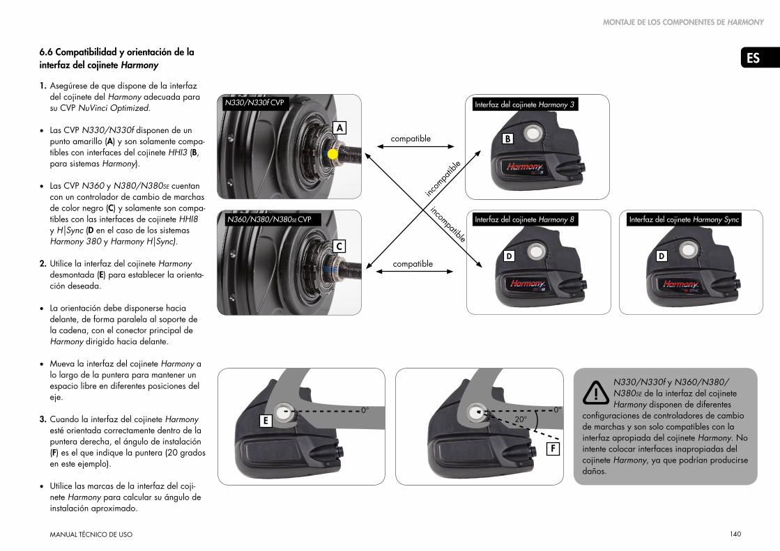
140
ES
MANUAL TÉCNICO DE USO
B
D
E
6.6 HarmonyTM Hub Interface Compatibi-lity & Orientation1. Asegúrese de que dispone de la interfaz
del cojinete del Harmony adecuada para su CVP NuVinci Optimized.
• Las CVP N330/N330f disponen de un punto amarillo (A) y son solamente compa-tibles con interfaces del cojinete HHI3 (B, para sistemas Harmony).
• Las CVP N360 y N380/N380SE cuentan con un controlador de cambio de marchas de color negro (C) y solamente son compa-tibles con las interfaces de cojinete HHI8 y H|Sync (D en el caso de los sistemas Harmony 380 y Harmony H|Sync).
2. Utilice la interfaz del cojinete Harmony desmontada (E) para establecer la orienta-ción deseada.
• La orientación debe disponerse hacia delante, de forma paralela al soporte de la cadena, con el conector principal de Harmony dirigido hacia delante.
• Mueva la interfaz del cojinete Harmony a lo largo de la puntera para mantener un espacio libre en diferentes posiciones del eje.
3. Cuando la interfaz del cojinete Harmony esté orientada correctamente dentro de la puntera derecha, el ángulo de instalación (F) es el que indique la puntera (20 grados en este ejemplo).
• Utilice las marcas de la interfaz del coji-nete Harmony para calcular su ángulo de instalación aproximado.
C
A
6.6 Compatibilidad y orientación de la interfaz del cojinete Harmony
N330/N330f y N360/N380/N380SE de la interfaz del cojinete Harmony disponen de diferentes
configuraciones de controladores de cambio de marchas y son solo compatibles con la interfaz apropiada del cojinete Harmony. No intente colocar interfaces inapropiadas del cojinete Harmony, ya que podrían producirse daños.
0° 0°
F
20°
compatible
compatible
incom
patib
le
D
incompatible
!
Interfaz del cojinete Harmony 3
Interfaz del cojinete Harmony 8 Interfaz del cojinete Harmony Sync
N330/N330f CVP
N360/N380/N380SE CVP
MONTAJE DE LOS COMPONENTES DE HARMONY

141
ES
MANUAL TÉCNICO DE USO
6.7 Instalación de la interfaz del cojinete Harmony
1. Desmonte el disco de retención antideslizamiento si está instalado (consulte la sección 6.2)
Las CVP de las series N330/N330f y N360/N380/N380SE disponen de diferentes configuraciones de
controladores de cambio de marchas y son solo compatibles con la interfaz apropiada del cojinete Harmony. Consulte la sección 6.6.
La posición del controlador de cambio de marchas no importa durante la instalación
de los productos Harmony; el proceso de calibración determinará automáticamente su posición.
2. Cuelgue la interfaz del cojinete Harmony sobre el eje derecho y alinee las partes planas del eje (A) en el ángulo de instalación determinado en la sección 6.6.
• También es posible colocar una arandela fija (B) sobre la interfaz del cojinete Harmony para alinear el ángulo de instalación.
A
B
C
C
!
!
MONTAJE DE LOS COMPONENTES DE HARMONY
3. Cuando el ángulo de instalación esté alineado, coloque la interfaz del cojinete Harmony completamente en el controlador de cambio de marchas y la tuerca de acanalado hasta que esté alineada con la tuerca de acanalado, tal y como se muestra en la imagen.
4. Enrosque la tuerca derecha (C) en el eje, con el borde dentado hacia fuera, y apriétela 10-15 Nm (7-11 ft-lb).
5. Monte la rueda trasera siguiendo los pasos de la sección 5.2.

142
ES
MANUAL TÉCNICO DE USO
6.8 Instalación del controlador Harmony H8
1. Instale la palanca de freno derecha siguiendo las instrucciones del proveedor.
2. Deslice el controlador H8 (A) en el manillar.
3. Instale el puño derecho (B) en el manillar siguiendo las instrucciones del proveedor.
4. 4. Coloque el controlador de tal forma que el ciclista pueda ver la pantalla (C) y que el cable no esté obstruido.
• Apriete el perno de fijación 2,0-2,5 Nm (18-22 in-lb).
Nunca use lubricantes ni disolventes para instalar puños de manillares.
Asegúrese de que el controlador y la palanca de freno funcionan correctamente y sin obstrucciones
(reajustar en caso necesario).
Nunca conduzca sin puños de manillares. El puño giratorio de la palanca de cambio podría soltarse.
Esto podría causar heridas graves.
MONTAJE DE LOS COMPONENTES DE HARMONY
6.9 Instalación del controlador Harmony H3
1. El controlador H3 está montado en una base de goma que envuelve un manillar estándar, al lado del puño.
2. Utilice el aro tórico para ajustar el controlador H3 y colóquelo de tal forma que el ciclista pueda ver la pantalla y que el cable no esté obstruido.
• El controlador H3 se puede montar tanto a la derecha como a la izquierda del manillar
C
A
B
!
!
!
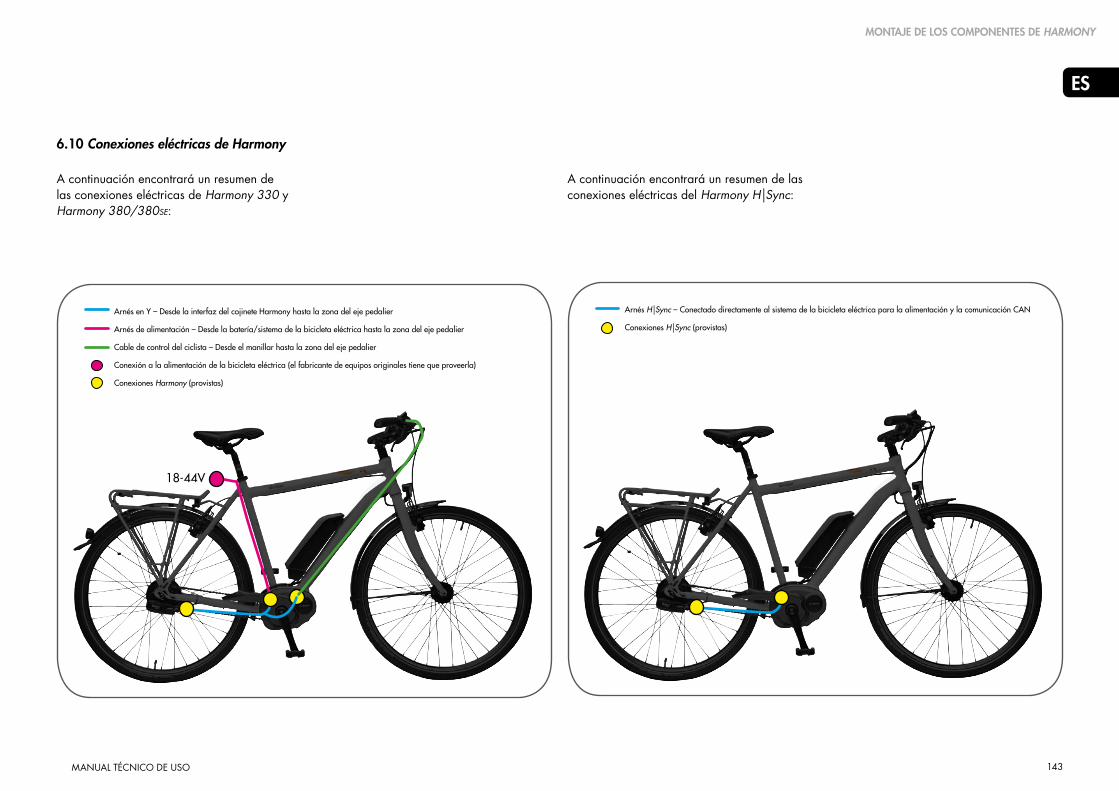
143
ES
MANUAL TÉCNICO DE USO
6.10 Conexiones eléctricas de Harmony
A continuación encontrará un resumen de las conexiones eléctricas de Harmony 330 y Harmony 380/380SE:
MONTAJE DE LOS COMPONENTES DE HARMONY
A continuación encontrará un resumen de las conexiones eléctricas del Harmony H|Sync:
Arnés en Y – Desde la interfaz del cojinete Harmony hasta la zona del eje pedalier
Arnés de alimentación – Desde la batería/sistema de la bicicleta eléctrica hasta la zona del eje pedalier
Cable de control del ciclista – Desde el manillar hasta la zona del eje pedalier
Conexión a la alimentación de la bicicleta eléctrica (el fabricante de equipos originales tiene que proveerla)
Conexiones Harmony (provistas)
18-44V
Arnés H|Sync – Conectado directamente al sistema de la bicicleta eléctrica para la alimentación y la comunicación CAN
Conexiones H|Sync (provistas)

144
ES
MANUAL TÉCNICO DE USO
7. Instrucciones de servicio Harmony
7.1 Mantenimiento o repuesto de la rueda libre
1. Desmonte la rueda trasera siguiendo los pasos de la sección 5.1.
2. Desmonte la interfaz del cojinete del Harmony y el anillo de velocidad de entrada siguiendo los pasos en orden inverso de la sección 6.7 y la sección 6.3.
3. Véase la vista detallada en la sección 8.3.
Desmonte el anillo de retención del piñón (12), el separador de piñones (13, en caso de que esté instalado) y el piñón (14).
4. Desmonte el anillo de retención (15) del controlador de cambio de marchas y quite el ensamblaje de la rueda libre (16).
5. En caso de reparación o sustitución, utilice un aceite de peso medio o una grasa ligera resistente al agua y compruebe el trinquete y el resorte.
6. Desmonte el anillo de retención interior (17), el rodamiento de aguja (18) y el protector derecho (19) si estas piezas han de reemplazarse.
7. Instale los nuevos componentes o los componentes de reparación de la rueda libre según la vista detallada de la sección 8.3.
INSTRUCCIONES DE SERVICIO HARMONY
1918171615
15
18
19
15
16
8. Instale el piñón y los componentes de Harmony siguiendo los pasos 2 y 3 mencionados anteriormente.
9. Monte la rueda trasera siguiendo los pasos de la sección 5.2.

145
ES
MANUAL TÉCNICO DE USO
7.2 Desmontar las configuraciones de los frenos
Véase la vista detallada en la sección 8.3 para ver cifras y descripciones.
Desmonte la rueda trasera siguiendo los pasos de la sección 5.1.
Desmontar las piezas de los frenos de rodillo
1. Desmonte la tuerca del eje izquierdo (1), la arandela fija izquierda (2) y la tuerca izquierda (3).
2. Asegure la rueda y utilice la herramienta de servicio N360T-BKAD-01 para desmontar el anillo de cierre del freno (6) y desmonte el adaptador del freno de rodillo (7) de la CVP.
Desmontar las piezas de los frenos de llanta
1. Desmonte la tuerca del eje izquierdo (1), la arandela fija izquierda (2), la tuerca izquierda (3) y la arandela cóncava (4).
2. Con un objeto delgado y plano levante y retire la cubierta del freno de llanta (5).
INSTRUCCIONES DE SERVICIO HARMONY
!
Desmontar las piezas de los frenos de disco
1. Desmonte la tuerca del eje izquierdo (1), la arandela fija izquierda (2), la tuerca izquierda (3) y la arandela cóncava (4).
2. Asegure la rueda y utilice la herramienta
de servicio N360T-BKAD-01 para desmontar el anillo de cierre del freno (6) y desmonte tanto el protector del freno (8) como el adaptador del freno de disco (9) de la CVP.

146
ES
MANUAL TÉCNICO DE USO
7.3 Instalar las configuraciones del freno
Véase la vista detallada en la sección 8.3 para ver cifras y descripciones.
Instalar las piezas de los frenos de rodillo
1. Instale el adaptador del freno de rodillo (7) y aplique un compuesto sellarroscas de alta resistencia (equivalente a Loctite® 277™) alrededor de un roscado completo del anillo de cierre del freno (6).
2. Con la herramienta de servicio N360T-BKAD-01, coloque y apriete el anillo de cierre del freno (6) 55-65 Nm (41-48 ft-lb).
3. Tras colocar el freno de rodillo, coloque y apriete la tuerca izquierda (3) 30-35 Nm (22-26 ft-lb).
Instalar las piezas de los frenos de llanta
1. Presione la cubierta del freno de llanta (5) hasta que esté perfectamente colocada, seguida de la arandela cóncava (4).
2. Coloque y apriete la tuerca izquierda (3) 30-35 Nm (22-26 ft-lb).
INSTRUCCIONES DE SERVICIO HARMONY
Instalar las piezas de los frenos de disco
1. Instale el adaptador del freno de disco (9) y el protector del freno (8) y aplique un compuesto sellarroscas de alta resistencia (equivalente a Loctite® 277™) alrededor de un roscado completo del anillo de cierre del freno (6).
2. Con la herramienta de servicio N360T-
BKAD-01, coloque y apriete el anillo de cierre del freno (6) 55-65 Nm (41-48 ft-lb).
3. Coloque y apriete la tuerca izquierda (3) 30-35 Nm (22-26 ft-lb).
!

147
ES
MANUAL TÉCNICO DE USO
8. Datos técnicos Harmony
DATOS TÉCNICOS HARMONY
8.1 Especificaciones CVP
Cojinete N330/N330f
Colores del cojinete Plata o negro
Ratio de velocidad De variación continua dentro de la relación de marchas
Relación de marchas 330 % nominal, de 0,5 en marchas cortas a 1,65 en sobremarcha
Controlador H3
Otro controlador compatible –
Cambio de velocidades Puño de giro variable, ¾ de giro
Interfaz del cojinete HHI3
Otras IC compatibles –
Configuraciones del radio De 32 o 36 orificios
Configuraciones del freno Disco, llanta o rodillo
Peso CVP 2450 gramos
Ancho de la puntera 135 mm, horizontal o vertical
Longitud del eje 183 mm
Roscas del eje M10 x 1
Cadena 49.0 ± 0.5mm
Correa (Gates) 45.5 ± 0.5 mm
Correa (Conti-Tech) 46.2 ± 0.5 mm
Tamaños de los piñones 16-22 dientes (cadena)
20-28 dientes (correa)
Tipos de piñones 9 surcos acanalados estándar, planos en un lado
Definición del ratio del piñón Dientes del piñón delantero/dientes del piñón trasero
Ratio mínimo del piñón (bicicletas de pedales) 1,8 (Tabla en la sección 8.2)
Ratio mínimo del piñón (bicicletas eléctricas con motor frontal) 1.8 (Tabla en la sección 8.2)
Ratio mínimo del piñón (bicicletas eléctricas con motor central) 2.1 (Tabla en la sección 8.2)
Diámetro de la brida del radio 125.0 mm
Brida del radio, del centro al extremo izquierdo 26.0 mm
Brida del radio, del centro al extremo derecho 26.0 mm
Harmony 330
Cojinete N380/N380SE
Colores del cojinete Plata o negro
Ratio de velocidad De variación continua dentro de la relación de marchas
Ratio range 380 % nominal, de 0,5 en marchas cortas a 1,9 en sobremarcha
Controlador H8
Otro controlador compatible H|Sync
Cambio de velocidades Puño de giro variable, ¾ de giro
Interfaz del cojinete HHI8
Otras IC compatibles H|SYNC, (Interfaces del cojinete Harmony MY12-15)*
Configuraciones del radio De 32 o 36 orificios
Configuraciones del freno Disco, llanta o rodillo
Peso CVP 2450 gramos
Ancho de la puntera 135 mm, horizontal o vertical
Longitud del eje 183 mm
Roscas del eje M10 x 1
Cadena 49.0 ± 0.5mm
Correa (Gates) 45.5 ± 0.5 mm
Correa (Conti-Tech) 46.2 ± 0.5 mm
Tamaños de los piñones 16-22 dientes (cadena)
20-28 dientes (cadena)**
20-28 dientes (correa)
Tipos de piñones 9 surcos acanalados estándar, planos en un lado
Definición del ratio del piñón Dientes del piñón delantero/dientes del piñón trasero
Ratio mínimo del piñón (bicicletas de pedales) 1,8 (Tabla en la sección 8.2)
Ratio mínimo del piñón (bicicletas eléctricas con motor frontal) 1.8 (Tabla en la sección 8.2)
Ratio mínimo del piñón (bicicletas eléctricas con motor central) 2.1 (Tabla en la sección 8.2)
Diámetro de la brida del radio 125.0 mm
Brida del radio, del centro al extremo izquierdo 26.0 mm
Brida del radio, del centro al extremo derecho 26.0 mm
Harmony 380/380SE
*Las interfaces del cojinete Harmony MY12-15 son solo compatibles con una cadena
**Estos datos se refieren a todas las interfaces del cojinete Harmony MY12-15 que son solo compatibles con una cadena

148
ES
MANUAL TÉCNICO DE USO
EN
DATOS TÉCNICOS HARMONY
8.2 Engranajes aprobados
Ratio mínimo del piñón de 2,1 para las bicicletas eléctricas con motor en medio de hasta 250 W
Ratio mínimo del piñón de 1,8 para todas las bicicletas de pedales y bicicletas eléctricas con
motor frontal
Ratio mínimo del piñón de 0,84 para las bicicletas eléctricas Bosch GEN2 de hasta 250 W
58 y superior
56
54
52
50
48
46
44
42
40
39
38
36
34
33
32
30
28
27 e inferior
58 y superior
56
54
52
50
48
46
44
42
40
39
38
36
34
33
32
30
28
27 e inferior
Engranajes aprobados CVP N330 (grupos de productos Nfinity 330, Nfinity 330f & Harmony 330)Engranajes aprobados N380 CVP (grupos de productos Nfinity 380, Nfinity 380SE
Harmony 380, Harmony 380/380SE & Harmony HISync)
Rued
a fro
ntal
de
cade
na e
stánd
ar/p
iñón
Rued
a fro
ntal
de
cade
na e
stánd
ar/p
iñón
24 y superior
23
22
21
20
19
18
17
16
15
14
13 e inferior
24 y superior
23
22
21
20
19
18
17
16
15
14
13 e inferior
Piñó
n fro
ntal
Bos
ch G
EN2
Piñó
n fro
ntal
Bos
ch G
EN2
16 17 18 19 20 21 22 23 24 26 28 16 17 18 19 20 21 22 23 24 26 28
Aprobado para cualquier bicicleta (incluso las bicicletas eléctricas de hasta 250 W) Aprobado para cualquier bicicleta (incluso las bicicletas eléctricas de hasta 350 W)
CVP N330 (grupos de productos Nfinity 330, Nfinity 330f & Harmony 330)CVP N380 (grupos de productos Nfinity 380, Nfinity 380SE, Harmony 380/380SE y Harmony HISync)
Ratio del piñón = dientes del piñón delantero/dientes del piñón trasero
No aprobado para ninguna bicicleta No aprobado para ninguna bicicleta
Los sistemas Nfinity 380, Nfinity
380SE, Harmony 380/380SE
y Harmony HISync disponen de
la CVP N380 y son compatibles con sistemas
de bicicletas eléctricas con motor en medio de
hasta 350 W y con el engranaje aprobado
que se puede consultar en la tabla asociada
N380 en esta página.
!Aprobado para bicicletas de pedales y bicicletas eléctricas de motor con cojinete frontal (no aprobado para bicicletas eléctricas con motor en el medio)
3,6 3,4 3,2 3,1 2,9 2,8 2,6 2,5 2,4 2,2 2,1
3,5 3,3 3,1 2,9 2,8 2,7 2,5 2,4 2,3 2,2 2,0
3,4 3,2 3,0 2,8 2,7 2,6 2,5 2,3 2,3 2,1 1,9
3,3 3,1 2,9 2,7 2,6 2,5 2,4 2,3 2,2 2,0 1,9
3,1 2,9 2,8 2,6 2,5 2,4 2,3 2,2 2,1 1,9 1,8
3,0 2,8 2,7 2,5 2,4 2,3 2,2 2,1 2,0 1,8 1,7
2,9 2,7 2,6 2,4 2,3 2,2 2,1 2,0 1,9 1,8 1,6
2,8 2,6 2,4 2,3 2,2 2,1 2,0 1,9 1,8 1,7 1,6
2,6 2,5 2,3 2,2 2,1 2,0 1,9 1,8 1,8 1,6 1,5
2,5 2,4 2,2 2,1 2,0 1,9 1,8 1,7 1,7 1,5 1,4
2,4 2,3 2,2 2,1 2,0 1,9 1,8 1,7 1,6 1,5 1,4
2,4 2,2 2,1 2,0 1,9 1,8 1,7 1,7 1,6 1,5 1,4
2,3 2,1 2,0 1,9 1,8 1,7 1,6 1,6 1,5 1,4 1,3
2,1 2,0 1,9 1,8 1,7 1,6 1,5 1,5 1,4 1,3 1,2
2,1 1,9 1,8 1,7 1,7 1,6 1,5 1,4 1,4 1,3 1,2
2,0 1,9 1,8 1,7 1,6 1,5 1,5 1,4 1,3 1,2 1,1
1,9 1,8 1,7 1,6 1,5 1,4 1,4 1,3 1,3 1,2 1,1
1,8 1,6 1,6 1,5 1,4 1,3 1,3 1,2 1,2 1,1 1,0
1,7 1,6 1,5 1,4 1,4 1,3 1,2 1,2 1,1 1,0 1,0
1,50 1,41 1,33 1,26 1,20 1,14 1,09 1,04 1,00 0,92 0,86
1,44 1,35 1,28 1,21 1,15 1,10 1,05 1,00 0,96 0,88 0,82
1,38 1,29 1,22 1,16 1,10 1,05 1,00 0,96 0,92 0,85 0,79
1,31 1,24 1,17 1,11 1,05 1,00 0,95 0,91 0,88 0,81 0,75
1,25 1,18 1,11 1,05 1,00 0,95 0,91 0,87 0,83 0,77 0,71
1,19 1,12 1,06 1,00 0,95 0,90 0,86 0,83 0,79 0,73 0,68
1,13 1,06 1,00 0,95 0,90 0,86 0,82 0,78 0,75 0,69 0,64
1,06 1,00 0,94 0,89 0,85 0,81 0,77 0,74 0,71 0,65 0,61
1,00 0,94 0,89 0,84 0,80 0,76 0,73 0,70 0,67 0,62 0,57
0,94 0,88 0,83 0,79 0,75 0,71 0,68 0,65 0,63 0,58 0,54
0,88 0,82 0,78 0,74 0,70 0,67 0,64 0,61 0,58 0,54 0,50
0,81 0,76 0,72 0,68 0,65 0,62 0,59 0,57 0,54 0,50 0,46
Aprobado para bicicletas de pedales y bicicletas eléctricas de motor con cojinete frontal (no aprobado para bicicletas eléctricas con motor en el medio)
Ratio mínimo del piñón de 2,0 para las bicicletas eléctricas con motor en medio de hasta 350 W
Ratio mínimo del piñón de 1,8 para todas las bicicletas de pedales y bicicletas eléctricas con
motor frontal
Ratio mínimo del piñón de 0,80 para las bicicletas eléctricas Bosch GEN2 de hasta 350 W
Ratio del piñón = dientes del piñón delantero/dientes del piñón trasero
Los sistemas Nfinity 330,
Nfinity 330f y Harmony
330 disponen de la CVP
N330 y son compatibles con sistemas de
bicicletas eléctricas con motor en medio
de hasta 250 W y con el engranaje
aprobado que se puede consultar en la
tabla asociada N330 en esta página.
!

149
ES
MANUAL TÉCNICO DE USO
8.3 Vista detallada
DATOS TÉCNICOS HARMONY
18 16 14 12 10
19 17 15 13 11 2Configuración del freno de llanta
Configuración del freno de rodillo
Configuración del freno de disco
Tuerca del eje
Arandela fija
Tuerca izquierda
Arandela cóncava
Cubierta del freno de llanta
Anillo de cierre del freno
Adaptador del freno de rodillo
Protector del freno
Adaptador del freno de disco
Tuerca derecha
Interfaz del cojinete
Anillo de retención del piñón
Separador de piñones
Piñón
Anillo de retención (rueda suelta)
Ensamblaje de la rueda libre
Anillo de retención (interior)
Rodamiento de aguja
Protector derecho
A
B
C
1
2
3
4
5
6
7
8
9
10
11
12
13
14
15
16
17
18
19
7
9
48
6
4 5
1
2
3
A
B
C
(Opcional: se puede utilizar con piñones de 2,3 mm de grosor)
No provisto
Lado izquierdo(sin transmisión)
Lado derecho (con transmisión)
1

150
ES
MANUAL TÉCNICO DE USO
8.4 Dimensiones de la CVP y de la palanca de cambio Harmony
DATOS TÉCNICOS HARMONY
Controlador H3 Controlador H8
CVP con la interfaz del cojinete Harmony CVP con la interfaz del cojinete Harmony Interfaz del cojinete Harmony
12532 AND 36 SPOKECONFIGURATIONS
AVAILABLE
2.9SPOKEHOLE
SCALE 0.500
SCALE 0.500
183 AXLE WIDTH
135 DROPOUT WIDTH
VERSIONDISC BRAKE
ISO 6 BOLT16.0
41
73
67.5CENTERLINE
49.0CHAINLINE
26.026.0
MULTI-GEAR(2.3MM OR 3/32")CHAINS ANDSPROCKETS ONLY
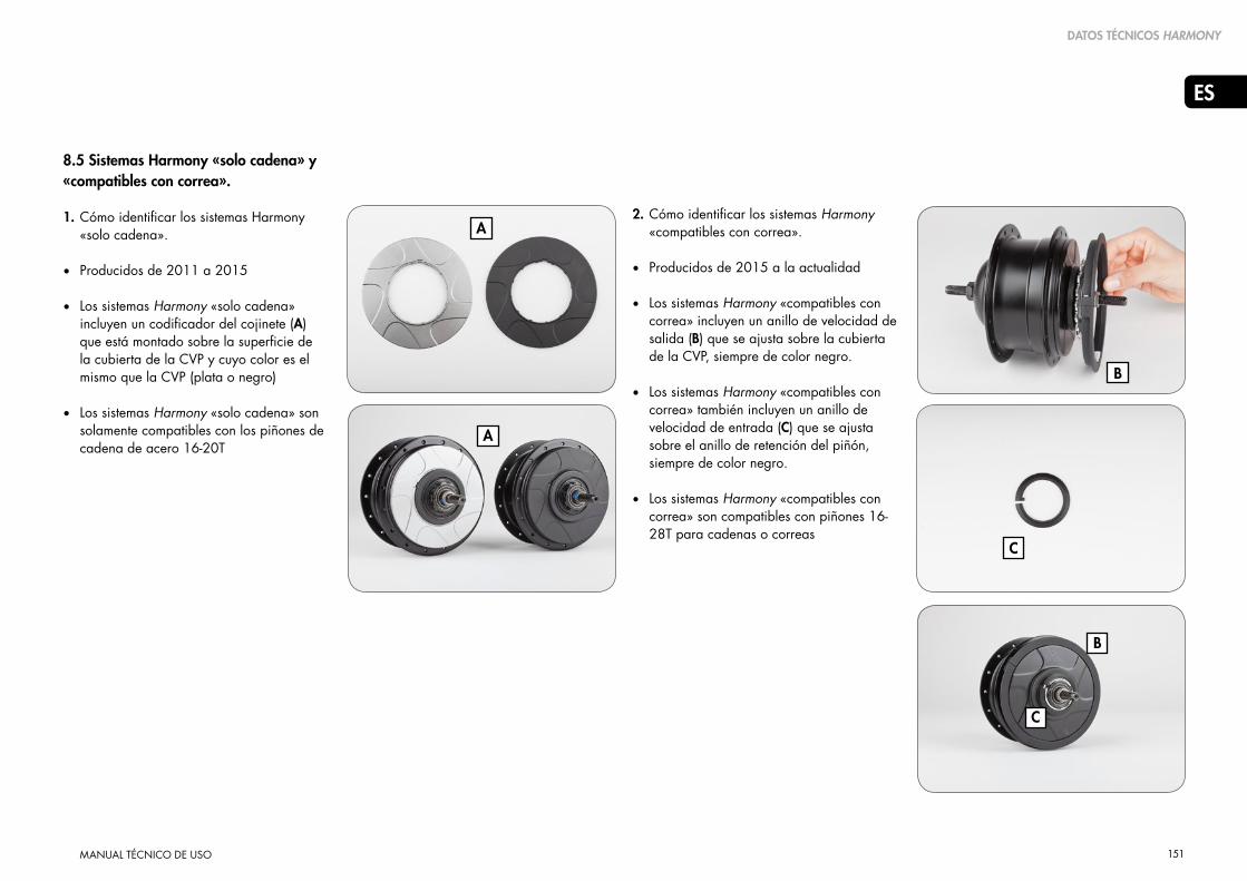
151
ES
MANUAL TÉCNICO DE USO
DATOS TÉCNICOS HARMONY
8.5 Sistemas Harmony «solo cadena» y «compatibles con correa».
1. Cómo identificar los sistemas Harmony «solo cadena».
• Producidos de 2011 a 2015
• Los sistemas Harmony «solo cadena» incluyen un codificador del cojinete (A) que está montado sobre la superficie de la cubierta de la CVP y cuyo color es el mismo que la CVP (plata o negro)
• Los sistemas Harmony «solo cadena» son solamente compatibles con los piñones de cadena de acero 16-20T
A
B
C
A
B
C
2. Cómo identificar los sistemas Harmony «compatibles con correa».
• Producidos de 2015 a la actualidad
• Los sistemas Harmony «compatibles con correa» incluyen un anillo de velocidad de salida (B) que se ajusta sobre la cubierta de la CVP, siempre de color negro.
• Los sistemas Harmony «compatibles con correa» también incluyen un anillo de velocidad de entrada (C) que se ajusta sobre el anillo de retención del piñón, siempre de color negro.
• Los sistemas Harmony «compatibles con correa» son compatibles con piñones 16-28T para cadenas o correas

152
ES
MANUAL TÉCNICO DE USO
AVISO DE PROPIEDAD INTELECTUAL
9. Aviso de propiedad intelectual
Las unidades de control NuVinci Optimized N360, Harmony & Harmony H|Sync
Aviso de Propiedad Intelectual
Al adquirir o utilizar estos componentes NuVinci Optimized y la bicicleta que los incorpora, usted acepta los siguientes términos y condiciones. Si no está de acuerdo con estos términos y condiciones, deberá devolver los componentes NuVinci Optimized a su proveedor en un plazo de tres (3) días para obtener un reembolso completo. Los componentes NuVinci Optimized aquí vendidos solamente han de usarse en la rueda trasera de una bicicleta por razones habituales y razonables y según las instrucciones adjuntas. Acepta no utilizar los componentes NuVinci Optimized para cualquier otro uso o propósito, incluyendo, entre otros, la ingeniería inversa y la reproducción. No se recomienda el uso no autorizado de los componentes NuVinci Optimized e invalidará todas las garantías aplicables. En caso de que se creen mejoras o invenciones con esos componentes, en la medida que lo permita la ley aplicable, Fallbrook Technologies Inc. y sus licenciatarios dispondrán de una licencia libre de regalías, mundial, perpetua y no exclusiva a todos los derechos de esas mejoras o invenciones.
Los componentes de NuVinci Optimized que se venden aquí y que incluyen, pero no están limitados al cojinete trasero, al controlador y a la palanca de cambio de velocidades están protegidos por las patentes estadounidenses 7,871,353; 7,885,747; 7,959,533; 8,321,097, 8,376,903; 8,398,518; 8,506,452; 8,626,409; y las patentes europeas EP2171312; EP2234869; la patente danesa núm. 1954959; la patente española ES2424652; y otras patentes. Otras solicitudes de patentes estadounidenses y extranjeras están a la espera de Fallbrook Technologies Inc. y su filial Intellectual Property Co. LLC.
Los productos Harmony y H|Sync también incluyen software, firmware u otras informaciones digitales (comúnmente el «software») que pueden estar integrados o se pueden solicitar a Fallbrook Technologies o a sus representantes autorizados para su uso con los productos.
El software está protegido por leyes de derechos de autor en cada jurisdicción o país y está estrictamente prohibida cualquier reproducción, representación, uso o adaptación.
Fallbrook, NuVinci, N360, Harmony, Harmony H|Sync, sus logotipos estilizados y sus elementos asociados son marcas o marcas registradas de Fallbrook Technologies Inc.Bosch e Intuvia son marcas registradas de Robert Bosch GmbH.
Todos los derechos reservados. © 2015

153
ES
MANUAL TÉCNICO DE USO
10. Garantía
GARANTÍA
LA SIGUIENTE GARANTÍA ES UNA GARANTÍA VOLUNTARIA LIMITADA DE DOS AÑOS OFRECIDA POR FALLBROOK TECHNOLOGIES INC. (“FALLBROOK”). SE OFRECE A TODOS LOS COMPRADORES DE NUVINCI OPTIMIZED, N330, N330f, N360, N380, N380SE, C3, C8, C8S, H3, H8, NFINITY 330, NFINITY 330f, NFINITY 380, NFINITY N380SE, HARMONY 330, HARMONY 380, HARMONY 380SE, HARMONY H|SYNC, NFINITY HI, HHI3, HHI8, HHISYNC (COMÚNMENTE, LOS “PRODUCTOS FALLBROOK”).
EN VIRTUD DE LAS LEYES DE CIERTOS PAÍSES (COMO ALEMANIA O LOS PAÍSES BAJOS), AL COMPRADOR LE ASISTEN DERECHOS LEGALES EN LO QUE RESPECTA A PRODUCTOS DEFECTUOSOS O QUE NO SE CONFORMAN CON EL CONTRATO DE VENTA. ESTOS DERECHOS PERMITEN AL COMPRADOR EXIGIR UNA REPARACIÓN O SUSTITUCIÓN DE DICHOS PRODUCTOS, SIN COSTE ALGUNO, O EN CIERTAS CONDICIONES, UN DESCUENTO O REEMBOLSO POR PARTE DEL VENDEDOR. ESTA GARANTÍA VOLUNTARIA NO AFECTA A SUS DERECHOS LEGALES. SI USTED VIVE EN UNO DE ESTOS PAÍSES, CUANDO ADQUIERA PRODUCTOS FALLBROOK, ADEMÁS DE SUS DERECHOS LEGALES, TAMBIÉN TENDRÁ DERECHO A RECLAMACIONES EN BASE A LA GARANTÍA LIMITADA DE FALLBROOK QUE SE DESCRIBE A CONTINUACIÓN. ESTAS RECLAMACIONES EXISTEN SIMULTÁNEAMENTE CON SUS DERECHOS LEGALES. EN CASO DE QUE SU PRODUCTO FALLBROOK ESTÉ DEFECTUOSO O NO SE CONFORME CON EL CONTRATO DE VENTA, SIEMPRE QUE LA GARANTÍA LIMITADA SEA VIGENTE, PUEDE ELEGIR PRESENTAR UNA RECLAMACIÓN EN VIRTUD DE LA LEY DE SU PAÍS O EN VIRTUD DE LA GARANTÍA LIMITADA DE FALLBROOK.
¿Qué cubre esta garantía?
Fallbrook Technologies Inc. (Fallbrook) avala todas las productos Fallbrook que presenten algún defecto de material o de fabricación. Esta garantía solamente se otorga al comprador original y no es transferible. (Algunos países o estados no permiten la restricción de la cobertura de la garantía al comprador original, así que puede que la restricción no se le aplique a usted). Si usted ha adquirido su producto Fallbrook como parte de otro producto, esta garantía no reemplaza de ninguna forma ni supone la extensión de garantía del fabricante de ese producto. La otra garantía es la responsabilidad exclusiva del fabricante de ese producto.
¿Qué duración tiene esta garantía?
El periodo de garantía es de dos años a partir de la fecha de la compra original.
¿Qué hará Fallbrook?
Fallbrook, a su entera discreción, reparará, reemplazará o reembolsará el coste de la unidad defectuosa.
¿Qué no cubre esta garantía?
Esta garantía no se aplica a las siguientes circunstancias:
• El deterioro normal de los componentes que puedan desgastarse, como por ejemplo, las juntas y anillos de goma, las ruedas direccionales del tensor de cadena (en caso de que se aplique), los mangos de goma de giro y los cables de la palanca de cambio.
• El daño de piezas no manufacturadas por Fallbrook o sus entidades vinculadas (como las punteras y las cadenas).
• La mano de obra necesaria para desmontar, reajustar y reensamblar el producto en la bicicleta.
• Un producto utilizado en una instalación que no sea en una bicicleta para un solo ciclista. Los tándems no están cubiertos.
• Un producto que se haya instalado de forma incorrecta o no se haya ajustado de acuerdo con el manual técnico de instalación de Nfinity 330, Nfinity 330f, Nfinity 380, Nfinity 380SE, Harmony 330, Harmony 380, Harmony 380SE o Harmony H|Sync, que se puede consultar en http://www.nuvincicycling.com/en/service/downloads.html
• Un producto que se haya desmontado más allá del alcance de la documentación (los manuales técnicos de uso de la CVP NuVinci Optimized con el sistema de cambios Harmony o Nfinity).

154
ES
MANUAL TÉCNICO DE USO
GARANTÍA
• Un producto que haya sido modificado o cuyo numero de serie o código de fecha se haya alterado, desfigurado o eliminado.
• Un autre produit que le N330f utilisé à des fins commerciales sans pré-autorisation écrite de Fallbook. Seul N330f peut être utilisé à des fins commerciales raisonnables et cette garantie sera limitée à un (1) an pour une telle utilisation commerciale raisonnable.
• Daños al producto: - que Fallbrook determine que se hayan producido debido a un choque, impacto o abuso del producto; - debido a un uso del producto que Fallbrook, en total discreción, considere un uso extremo, como por ejemplo, downhill, freeride, estilo «North Shore» y BMX; - causados por alimentar el producto con motores eléctricos de más de 250 vatios para N330/N330f/N360 y más de 350 vatios para N380/N380SE; o por alimentar el producto con motores de combustión internos; - causados por utilizar el producto con motores eléctricos con un par de corriente continuo superior a 80 Nm y un par máximo superior a 90 Nm;
- debidos al uso del producto con un peso total (ciclista, cargamento y bicicleta) superior a 200 kg; - debidos al uso del producto fuera de los límites definidos del ratio de dientes de 1.8 a 1 en las bicicletas estándar y de 2.1 a 1 (N330/N330f) o de 2.0 a 1 (N380/N380SE) en las bicicletas eléctricas; - debidos al uso del producto en voltajes superiores a 50 V; - causados por el uso de piezas que no son compatibles, adecuadas o autorizadas por Fallbrook con el producto; o - que hayan tenido lugar durante el envío del producto.
¿Cómo conseguir un servicio de garantía?
Las reclamaciones en virtud de esta garantía han de llevarse a cabo mediante el distribuidor a través de quien adquirió el vehículo o componente de Fallbrook, o mediante un distribuidor autorizado de los componentes NuVinci Optimized. Devuelva el componente de Fallbrook al distribuidor junto con la factura o recibo original y fechado. El distribuidor se pondrá en contacto con el servicio de atención al cliente de Fallbrook para gestionar su reclamación de garantía.
Los distribuidores que soliciten una reclamación de garantía han de contactar con el servicio de atención al cliente de Fallbrook para obtener una autorización de devolución por garantía. El distribuidor tendrá que devolver el producto a Fallbrook junto con la prueba satisfactoria de la fecha de compra.

155
ES
MANUAL TÉCNICO DE USO
GARANTÍA
Limitaciones de la garantía
ESTA GARANTÍA LIMITADA ES LA EXCLUSIVA Y ÚNICA GARANTÍA DE FALLBROOK RELACIONADACON EL PRODUCTO Y REEMPLAZA CUALQUIER OTRA GARANTÍA. EN LO MEDIDA QUE LO PERMITALA LEGISLACIÓN APLICABLE, SE EXCLUYE Y SE RECHAZA CUALQUIER GARANTÍA NO DISPUESTA AQUÍ DE FORMA EXPLÍCITA O IMPLÍCITA, INCLUYENDO CUALQUIER GARANTÍA IMPLÍCITA DE COMERCIABILIDAD O ADECUACIÓN PARA UN FIN DETERMINADO. LA RESPONSABILIDAD DE FALLBROOK CON ESTA GARANTÍA LIMITADA SE LIMITA EXCLUSIVAMENTE A LAS RESPONSABILIDADES MENCIONADAS ANTERIORMENTE. EN CASO DE QUE UNA PROVISIÓN DE ESTA GARANTÍA LIMITADA SEA INVÁLIDA O NO SE PUEDA CUMPLIR EN VIRTUD DE LA LEY APLICABLE, SUS DEMÁS TÉRMINOS Y CONDICIONES TENDRÁN PLENA VALIDEZ Y EFECTO Y LA PROVISIÓN INVÁLIDA O INAPLICABLE SE INTERPRETARÁ DE TAL FORMA QUE SEA VÁLIDA Y APLICABLE.
Fallbrook se reserva el derecho de revisar esta garantía limitada sin previo aviso.
NuVinci CYCLINGSoporte y servicio – EE. UU.
Fallbrook Technologies Inc.Cedar Park, Texas 78613 EE. UU.
Línea gratuita EE. UU.: 1-888-NuVinci (688-4624)
Tel: +1 (512) 279-6200 Fax: +1 (512) 267-0159
NuVinci CYCLINGSoporte y servicio – Europa
Fallbrook Technologies InternationalPopovstraat 128013 RK Zwolle, Países Bajos
Alemania y Austria+49 2289 2939 [email protected]
Suiza+41 43 508 55 [email protected]
Soporte General Europa+31 38 7200 [email protected]