
NuPRO-A331 Full-Size PICMG 1.0 Intel Core i7/i5/i3 … Technologies; Automate the World. Manual...
102
Advance Technologies; Automate the World. Manual Rev.: 2.01 Revision Date: February 17, 2011 Part No: 50-13067-1010 NuPRO-A331 Full-Size PICMG 1.0 Intel® Core™ i7/i5/i3 Q57 Express Chipset SBC User’s Manual
Transcript of NuPRO-A331 Full-Size PICMG 1.0 Intel Core i7/i5/i3 … Technologies; Automate the World. Manual...

Advance Technologies; Automate the World.
Manual Rev.: 2.01
Revision Date: February 17, 2011
Part No: 50-13067-1010
NuPRO-A331Full-Size PICMG 1.0 Intel® Core™ i7/i5/i3
Q57 Express Chipset SBC
User’s Manual

Revision History
Revision Release Date Description of Change(s)
2.00 2010/12/31 Initial release
2.01 2011/02/17 Correct PICMG “1.3” to “1.0”, update DVI cable P/N, remove SATA power cable from packing list

Preface iii
NuPRO-A331
PrefaceCopyright 2010-2011 ADLINK Technology Inc.This document contains proprietary information protected by copy-right. All rights are reserved. No part of this manual may be repro-duced by any mechanical, electronic, or other means in any formwithout prior written permission of the manufacturer.
DisclaimerThe information in this document is subject to change without priornotice in order to improve reliability, design, and function and doesnot represent a commitment on the part of the manufacturer.
In no event will the manufacturer be liable for direct, indirect, spe-cial, incidental, or consequential damages arising out of the use orinability to use the product or documentation, even if advised ofthe possibility of such damages.
Environmental ResponsibilityADLINK is committed to fulfill its social responsibility to globalenvironmental preservation through compliance with the Euro-pean Union's Restriction of Hazardous Substances (RoHS) direc-tive and Waste Electrical and Electronic Equipment (WEEE)directive. Environmental protection is a top priority for ADLINK.We have enforced measures to ensure that our products, manu-facturing processes, components, and raw materials have as littleimpact on the environment as possible. When products are at theirend of life, our customers are encouraged to dispose of them inaccordance with the product disposal and/or recovery programsprescribed by their nation or company.
TrademarksProduct names mentioned herein are used for identification pur-poses only and may be trademarks and/or registered trademarksof their respective companies.

iv Preface
Using this Manual
Audience and ScopeThe NuPRO-A331 User’s Manual is intended for hardwaretechnicians and systems operators with knowledge of installing,configuring and operating industrial grade single board computers.
Manual OrganizationThis manual is organized as follows:
Preface: Presents important copyright notifications, disclaimers,trademarks, and associated information on the proper understand-ing and usage of this document and its associated product(s).
Chapter 1, Introduction: Introduces the NuPRO-A331, its fea-tures, specifications and mechanical drawing.
Chapter 2, Hardware Information: Provides information onboard layout, connectors and jumpers for configuring theNuPRO-A331.
Chapter 3, Getting Started: Illustrates how to install componentson the NuPRO-A331 such as CPU, heatsink, and memory mod-ules.
Chapter 4, Driver Installation: Provides information on how toinstall the NuPRO-A331 device drivers.
Chapter 5, BIOS Setup: Describes basic navigation for theAMIBIOS®8 BIOS setup utility.
Appendix A, Watchdog Timer: Presents information on imple-menting the watchdog timer.
Appendix B, System Resources: Presents information on I/Omapping, IRQ routing, and resource allocation.
Important Safety Instructions: Presents safety instructions allusers must follow for the proper setup, installation and usage ofequipment and/or software.
Getting Service: Contact information for ADLINK’s worldwideoffices.

Preface v
NuPRO-A331
ConventionsTake note of the following conventions used throughout thismanual to make sure that users perform certain tasks andinstructions properly.
NOTE:NOTE:
Additional information, aids, and tips that help users perform tasks.
CAUTION:
Information to prevent minor physical injury, component dam-age, data loss, and/or program corruption when trying to com-plete a task.
WARNING:
Information to prevent serious physical injury, component damage, data loss, and/or program corruption when trying to complete a specific task.

vi Preface
This page intentionally left blank.

Table of Contents vii
NuPRO-A331
Table of Contents
Revision History...................................................................... ii
Preface .................................................................................... iii
List of Figures ........................................................................ xi
List of Tables........................................................................ xiii
1 Introduction ........................................................................ 11.1 Overview.............................................................................. 11.2 Features............................................................................... 21.3 Specifications....................................................................... 31.4 Block Diagram ..................................................................... 51.5 Functional Description ......................................................... 61.6 Mechanical Drawing ............................................................ 81.7 I/O Connectivity ................................................................... 91.8 Power Consumption .......................................................... 101.9 Package Contents ............................................................. 14
2 Hardware Information ...................................................... 152.1 Rear Panel I/O Ports.......................................................... 152.2 Board Layout ..................................................................... 182.3 Onboard Connectors ......................................................... 192.4 Jumpers ............................................................................. 28
3 Getting Started ................................................................. 293.1 Installing the CPU .............................................................. 293.2 Installing the CPU Fan and Heatsink................................. 333.3 Installing Memory Modules ................................................ 343.4 Installing the Power Connectors ........................................ 36

viii Table of Contents
4 Driver Installation.............................................................. 374.1 Intel® Rapid Storage Technology Driver ........................... 374.2 Intel® Q57 Express Chipset Driver.................................... 384.3 Display Driver..................................................................... 384.4 Ethernet Driver................................................................... 394.5 Intel® Rapid Storage Technology Utility ............................ 394.6 TPM Driver......................................................................... 404.7 ISA Driver........................................................................... 404.8 Audio Driver ....................................................................... 414.9 Management Engine.......................................................... 41
5 BIOS Setup ........................................................................ 435.1 Starting the BIOS............................................................... 435.2 Main Setup......................................................................... 475.3 Advanced BIOS Setup....................................................... 48
5.3.1 CPU Configuration......................................................... 495.3.2 IDE Configuration .......................................................... 505.3.3 Super IO Configuration .................................................. 515.3.4 Hardware Health Configuration ..................................... 525.3.5 ACPI Settings ................................................................ 555.3.6 AHCI Configuration........................................................ 565.3.7 Remote Access Configuration ....................................... 575.3.8 Trusted Computing ........................................................ 595.3.9 USB Configuration ......................................................... 60
5.4 PCI/PnP Settings ............................................................... 625.4.1 IRQ/DMA ....................................................................... 625.4.2 Enable ISA PnP Configuration....................................... 62
5.5 Boot Settings ..................................................................... 635.5.1 Boot Settings Configuration ........................................... 635.5.2 Boot Device Priority ....................................................... 655.5.3 Boot Device Groups....................................................... 65
5.6 Security Setup.................................................................... 665.7 Chipset Setup .................................................................... 68

Table of Contents ix
NuPRO-A331
5.7.1 Graphics and Memory Configuration ............................. 695.7.2 PCH Configuration......................................................... 70
5.8 Exit Menu........................................................................... 71
A Appendix: Watchdog Timer.............................................. 73A.1 Sample Code ..................................................................... 73
B Appendix: System Resources.......................................... 77B.1 System Memory Map......................................................... 77B.2 Direct Memory Access Channels....................................... 77B.3 IO Map ............................................................................... 78B.4 Interrupt Request (IRQ) Lines............................................ 79
Important Safety Instructions .............................................. 85
Getting Service...................................................................... 87

x Table of Contents
This page intentionally left blank.

List of Figures xi
NuPRO-A331
List of FiguresFigure 1-1: NuPRO-A331 Block Diagram .......................................... 5Figure 1-2: NuPRO-A331 Board Dimensions .................................... 8Figure 2-1: Rear Panel I/O Ports...................................................... 15Figure 2-2: Connectors and Jumpers............................................... 18

xii List of Figures
This page intentionally left blank.
List of Tables xiii
NuPRO-A331
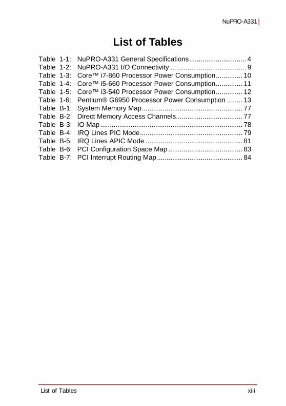
List of TablesTable 1-1: NuPRO-A331 General Specifications.............................. 4Table 1-2: NuPRO-A331 I/O Connectivity ........................................ 9Table 1-3: Core™ i7-860 Processor Power Consumption.............. 10Table 1-4: Core™ i5-660 Processor Power Consumption.............. 11Table 1-5: Core™ i3-540 Processor Power Consumption.............. 12Table 1-6: Pentium® G6950 Processor Power Consumption ........ 13Table B-1: System Memory Map..................................................... 77Table B-2: Direct Memory Access Channels................................... 77Table B-3: IO Map........................................................................... 78Table B-4: IRQ Lines PIC Mode...................................................... 79Table B-5: IRQ Lines APIC Mode ................................................... 81Table B-6: PCI Configuration Space Map ....................................... 83Table B-7: PCI Interrupt Routing Map............................................. 84

xiv List of Tables
This page intentionally left blank.
Introduction 1
NuPRO-A331
1 Introduction1.1 OverviewThe ADLINK NuPRO-A331 is a PICMG 1.0 Single BoardComputer (SBC) supporting the next-generation Intel® Core™i7/i5/i3 and Pentium® processors in LGA1156 package to deliver ascalable high performance platform for a wide array of industrialapplications. The NuPRO-A331 supports 32nm and 45nm processCPUs at up to 3.33GHz with integrated graphics and memorycontrollers, Direct Media Interface (DMI) and Flexible DisplayInterface (FDI) connectivity to the Intel® Q57 Express Chipset.Dual-channel DDR3 1066/1333 MHz memory is supported up to amaximum of 8GB in two DIMM slots.
These advanced features, coupled with dual PCI Express®-basedGigabit Ethernet, PCI Express Mini Card slot and diverse I/O andstorage make the NuPRO-A331 ideal for instrumentation andautomation control applications.

2 Introduction
1.2 FeaturesSupports Intel® Core™ i7/i5/i3 and Pentium® processors in LGA1156 packageIntegrated Intel® HD Graphics on dual core 32nm (Clarkdale) processorsPCI Express Mini Card slotDual Gigabit Ethernet8x USB 2.0 ports (2x on bracket, 6x onboard)6x SATA 3 Gb/s ports onboard6x COM ports (including 2x RS-232/422/485/485+)Watchdog Timer, Hardware MonitorOptional HD audio kit (DB-Audio2 daughter board)TPM hardware security chip (optional)RoHS compliant
NOTE:NOTE:
To purchase the optional DB-Audio2 daughter board, please contact your ADLINK sales representative.

Introduction 3
NuPRO-A331
1.3 Specifications
System
CPU
Intel® Core™ i7/i5/i3 and Pentium® Dual Core processors in LGA1156 package:• Intel® Core™ i7-860 Processor, 2.80 GHz, 8M Cache,
45nm, 95W, 4 cores/8 threads• Intel® Core™ i5-750 Processor, 2.66 GHz, 8M Cache,
45nm, 95W, 4 cores/4 threads• Intel® Core™ i5-660 Processor, 3.33 GHz, 4M Cache,
32nm, 73W, 2 cores/4 threads, HD Graphics• Intel® Core™ i3-540 Processor, 3.06 GHz, 4M Cache,
32nm, 73W, 2 cores/4 threads, HD Graphics• Intel® Pentium® G6950 Processor, 2.80 GHz,
3M Cache, 32nm, 73W, 2 cores/2 threads, HD GraphicsChipset • Intel® Q57 Platform Controller Hub
Memory • Two 240-pin DIMM sockets support dual-channel 1066/1333MHz DDR3 (up to 8GB)
BIOS • AMI BIOS in 64-Mbit SPI Flash
Audio • Intel® High Definition Audio support via DB-Audio2 daughter board
Watch Dog Timer • 1-255 second/minute programmable and can generate system reset.
Hardware Monitor
• CPU/System temperature, fan speed and onboard DC voltage
TPM • Infineon SLB 9635 TT 1.2 (NuPRO-A331DV only)Operating Systems
• Windows® XP, 7 32/64-bit, Server 2008; Fedora™ 12, Redhat Enterprise Linux 5

4 Introduction
Table 1-1: NuPRO-A331 General Specifications
I/O InterfacesSerial ATA • 6x SATA 3 Gb/s ports onboard
I/O Ports
• 2x USB 2.0 port on rear panel, 6x via onboard header• 6x serial ports via onboard pin-header
(4x RS-232, 2x RS-232/422/485/485+)• 2x GbE RJ45 ports (1x GbE on NuPRO-A331LV)• VGA port (Dsub-15)• Optional DVI-D via onboard header to bracket
(NuPRO-A331DV only)• PS/2 Keyboard/Mouse (onboard header)• 1 Parallel port
Expansion• PCI 32bit/33MHz• PCI-to-ISA Bridge: IT8888 (DMA not supported)• PCI Express Mini Card slot
DisplayIntegratedGraphics
• Integrated Intel® HD Graphics on dual core 32nm (Clarkdale) processors
ExternalGraphics
• Onboard PCI Express Mini Card slot for optional mPCIe-8770
Ethernet
Controller• Dual Intel® 82574L Gigabit Ethernet Controllers• Supports Preboot Execution Environment (PXE),
Wake-On-LANPorts • Two RJ-45 Ethernet ports
Mechanical and EnvironmentForm Factor • Standard full-size PICMG 1.0 SBCDimensions • 338 x 122 mm (L x W)Operating Temp. • 0ºC to 60ºCStorage Temp. • -20ºC to 80ºCRelative Humidity • 10% to 90% non-condensingSafety • CE, FCC Class A

Introduction 5
NuPRO-A331
1.4 Block Diagram
Figure 1-1: NuPRO-A331 Block Diagram
BIOS
PCHQ57
CPUCore i7/i5/i3
Pentium G6950
FDI
SPI
PCIeController
SATA
DDR3Memory
Controller
PCIController
USB2.0
HDA Audio
LPC
DMI
VGA
DDR3 DIMM1066/1333
Channel A
IntegratedHD Graphics
DDR3 DIMM1066/1333
Channel B
CRTDB-15
PCI32-bit/33MHz
KB/Mouse
LPT
RS-232
RS-232/422/485/485+
ITE IT8783FSuper I/O
IT8888PCI to ISA
PCIeMini Card
PCIe x1
PCIe x1
Intel 82574L
Intel 82574L
Header forDB-Audio2
USB 2.0(2x bracket, 6x onboard)
SATA ports (6x onboard)
LPC
ASM 1442Level Shift IC
DVI-Donboard header
ISA
MAX4885

6 Introduction
1.5 Functional Description
Processor SupportThe NuPRO-A331 is a single processor design for the latest IntelClarkdale (32nm) and Lynnfield (45nm) processors in LGA1156socket (Intel® Core™ i7/i5/i3, Pentium® G6950). An integratedmemory controller supports dual channel 1066/1333 MHz DDR3and integrated Intel® HD Graphics is supported on dual core32nm (Clarkdale) processors. Direct Media Interface (DMI) andFlexible Display Interface (FDI) provide connectivity to the Intel®Q57 Express Chipset.
Intel® Q57 Express ChipsetThe Intel® BD82Q57 Platform Controller Hub (PCH) combineswith the processor to provide a compact yet powerful 2-chip solu-tion. Direct Media Interface (DMI) is the chip-to-chip connectionbetween the processor and PCH. Intel® Flexible Display Interfacecarries display traffic from the integrated graphics in the processorto the legacy display connectors in the PCH. The PCH supports allother required interfaces including PCI Express, Serial ATA, USB2.0, PCI, LPC, and SPI.
Dual-Channel DDR3 MemoryTo meet the requirements of memory-intensive applications, theNuPRO-A331 has a dual-channel memory architecture supportingDDR3 1066/1333 MHz DIMMs. The key advantages of DDR3 arethe higher bandwidth and the increase in performance at lowerpower than DDR2. DDR3 memory technology meets the require-ments of the latest 3D graphics, multimedia, and network applica-tion, and boosts system performance by eliminating bottlenecks.
Gigabit EthernetThe NuPRO-A331 utilizes two Intel® 82574L Gigabit EthernetControllers connected to the PCIe bus of the Q57 PCH.Wake-on-LAN and PXE are supported.

Introduction 7
NuPRO-A331
Serial ATAThe NuPRO-A331 provides six Serial ATA ports with data transferrates of up to 3.0 GB/s. Intel® Rapid Storage Technology supportsAHCI and RAID 0/1/5/10 functionality.
Universal Serial Bus (USB) 2.0The NuPRO-A331 provides eight USB 2.0 ports supporting trans-fer speeds up to 480 Mbps. All ports are high-speed, fullspeed,and low-speed capable.
Hardware monitoringA built-in, proactive hardware monitoring system in the Super I/Omonitors the CPU temperature, system fan speed, and voltagelevels to prevent overheating and/or component damage, effecttimely failure detection, and ensure a stable supply of current forcritical components.
Watchdog TimerThe watchdog timer (WDT) monitors system operations based onuser-defined configurations. The WDT can be programmed for dif-ferent time-out periods, such as from 1 to 255 seconds or from 1 to255 minutes. The WDT generates a reset signal, then a resetrequest, after failure to strobe it within the programmed timeperiod. A register bit may be enabled to indicate if the watchdogtimer caused the reset event. The WDT register is cleared duringthe power-on sequence to enable the operating system to takeappropriate action when the watchdog generates a reboot.
Trusted Platform ModuleThe NuPRO-A331 optionally supports TPM ver. 1.2 (Trusted Plat-form Module) for secure storage of keys, passwords and digitalcertificates. Systems supporting TPM offer improved hard-ware-based security in numerous applications, such as file andfolder encryption, local password management, S-MIME e-mail,VPN and PKI authentication and wireless authentication for802.1x and LEAP.
8 Introduction
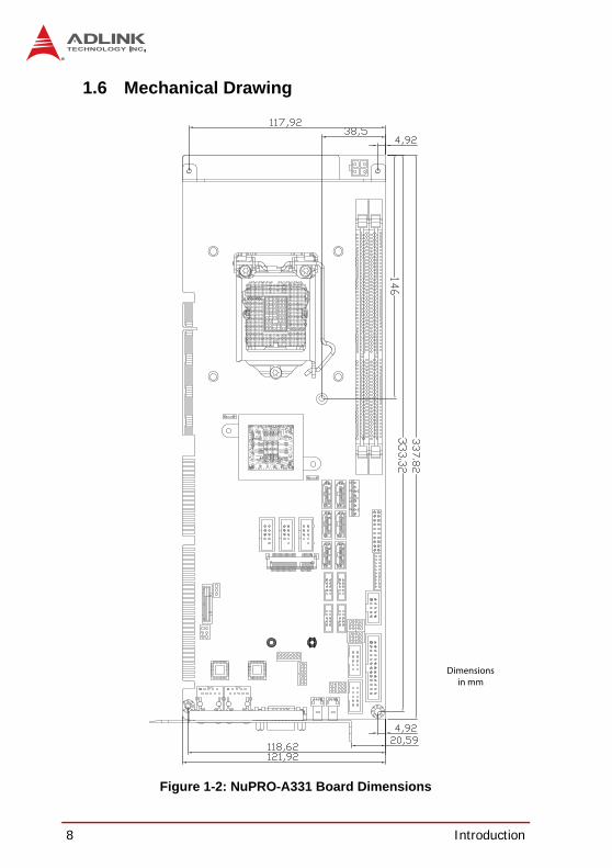
1.6 Mechanical Drawing
Figure 1-2: NuPRO-A331 Board Dimensions
Dimensionsin mm

Introduction 9
NuPRO-A331
1.7 I/O Connectivity
Table 1-2: NuPRO-A331 I/O Connectivity
I/O Bracket Onboard Golden Finger Remarks
VGA Y — — DB-15
DVI —Y
(DV only)—
cable w/ bracket optional
LAN1/2 (RJ-45)Y
(LV: 1x LAN)— —
Act/Link/Speed LEDs
PS/2 KB/MS — Y —cable w/ bracket
optional
USB Rear Panel 2 — —
USB headers — 6 — 2.54” pitch
COM1-2by cable
w/ bracketY — 2.54” pitch
COM3-6by cable
w/ bracketY — 2.00" pitch
Parallel port — Y — —
SATA — 6 — —
PCIe Mini Card — Y — —
PCI 32bit/33MHz — — Y —
ISA — — Y —
10 Introduction
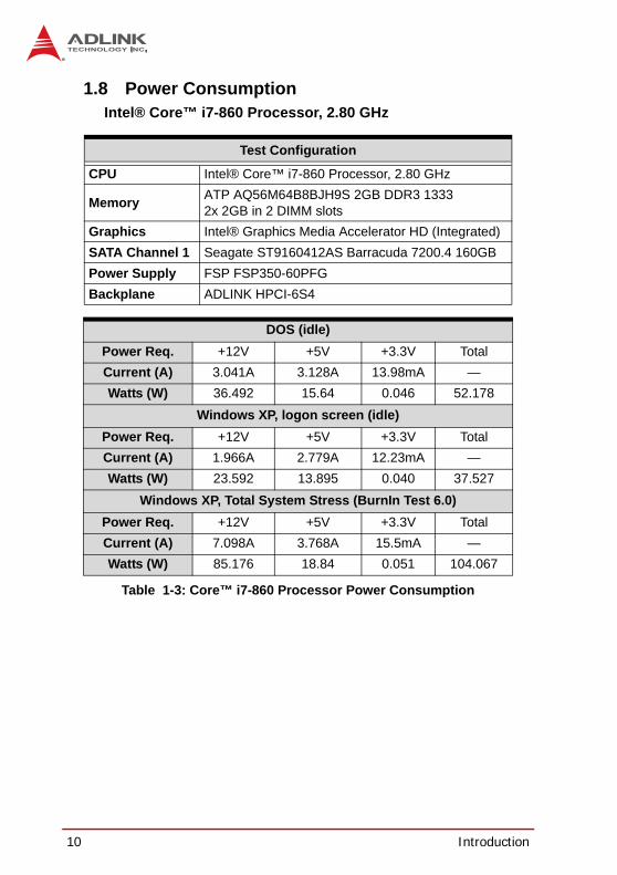
1.8 Power ConsumptionIntel® Core™ i7-860 Processor, 2.80 GHz
Table 1-3: Core™ i7-860 Processor Power Consumption
Test Configuration
CPU Intel® Core™ i7-860 Processor, 2.80 GHz
Memory ATP AQ56M64B8BJH9S 2GB DDR3 13332x 2GB in 2 DIMM slots
Graphics Intel® Graphics Media Accelerator HD (Integrated)SATA Channel 1 Seagate ST9160412AS Barracuda 7200.4 160GBPower Supply FSP FSP350-60PFGBackplane ADLINK HPCI-6S4
DOS (idle)Power Req. +12V +5V +3.3V TotalCurrent (A) 3.041A 3.128A 13.98mA —Watts (W) 36.492 15.64 0.046 52.178
Windows XP, logon screen (idle)Power Req. +12V +5V +3.3V TotalCurrent (A) 1.966A 2.779A 12.23mA —Watts (W) 23.592 13.895 0.040 37.527
Windows XP, Total System Stress (BurnIn Test 6.0)Power Req. +12V +5V +3.3V TotalCurrent (A) 7.098A 3.768A 15.5mA —Watts (W) 85.176 18.84 0.051 104.067

Introduction 11
NuPRO-A331
Intel® Core™ i5-660 Processor, 3.33 GHz
Table 1-4: Core™ i5-660 Processor Power Consumption
Test Configuration
CPU Intel® Core™ i5-660 Processor, 333 GHz
Memory ATP AQ56M64B8BJH9S 2GB DDR3 13332x 2GB in 2 DIMM slots
Graphics Intel® Graphics Media Accelerator HD (Integrated)SATA Channel 1 Seagate ST9160412AS Barracuda 7200.4 160GBPower Supply FSP FSP350-60PFGBackplane ADLINK HPCI-6S4
DOS (idle)Power Req. +12V +5V +3.3V TotalCurrent (A) 3.342 0.750 1.583 —Watts (W) 40.10 3.75 5.23 49.08
Windows XP, logon screen (idle)Power Req. +12V +5V +3.3V TotalCurrent (A) 1.602 0.730 1.572 —Watts (W) 19.22 3.65 5.19 28.06
Windows XP, Total System Stress (BurnIn Test 6.0)Power Req. +12V +5V +3.3V TotalCurrent (A) 3.360 1.199 1.644 —Watts (W) 40.32 5.99 5.43 51.74
12 Introduction
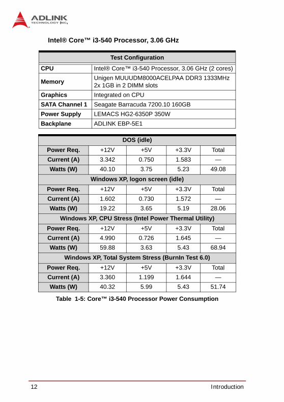
Intel® Core™ i3-540 Processor, 3.06 GHz
Table 1-5: Core™ i3-540 Processor Power Consumption
Test Configuration
CPU Intel® Core™ i3-540 Processor, 3.06 GHz (2 cores)
Memory Unigen MUUUDM8000ACELPAA DDR3 1333MHz2x 1GB in 2 DIMM slots
Graphics Integrated on CPUSATA Channel 1 Seagate Barracuda 7200.10 160GB Power Supply LEMACS HG2-6350P 350WBackplane ADLINK EBP-5E1
DOS (idle)Power Req. +12V +5V +3.3V TotalCurrent (A) 3.342 0.750 1.583 —Watts (W) 40.10 3.75 5.23 49.08
Windows XP, logon screen (idle)Power Req. +12V +5V +3.3V TotalCurrent (A) 1.602 0.730 1.572 —Watts (W) 19.22 3.65 5.19 28.06
Windows XP, CPU Stress (Intel Power Thermal Utility)Power Req. +12V +5V +3.3V TotalCurrent (A) 4.990 0.726 1.645 —Watts (W) 59.88 3.63 5.43 68.94
Windows XP, Total System Stress (BurnIn Test 6.0)Power Req. +12V +5V +3.3V TotalCurrent (A) 3.360 1.199 1.644 —Watts (W) 40.32 5.99 5.43 51.74

Introduction 13
NuPRO-A331
Intel® Pentium® G6950 Processor, 2.80 GHz
Table 1-6: Pentium® G6950 Processor Power Consumption
Test Configuration
CPU Intel® Pentium® G6950 Processor, 2.80 GHz (2 cores)
Memory Unigen MUUUDM8000ACELPAA DDR3 1333MHz2x 1GB in 2 DIMM slots
Graphics Integrated on CPUSATA Channel 1 Seagate Barracuda 7200.10 160GB Power Supply LEMACS HG2-6350P 350WBackplane ADLINK EBP-5E1
DOS (idle)Power Req. +12V +5V +3.3V TotalCurrent (A) 3.030 0.751 1.640 —Watts (W) 36.36 3.76 5.41 45.53
Windows XP, logon screen (idle)Power Req. +12V +5V +3.3V TotalCurrent (A) 1.594 0.728 1.621 —Watts (W) 19.13 3.64 5.35 28.12
Windows XP, CPU Stress (Intel Power Thermal Utility)Power Req. +12V +5V +3.3V TotalCurrent (A) 4.522 0.722 1.635 —Watts (W) 54.26 3.61 5.40 63.27
Windows XP, Total System Stress (BurnIn Test 6.0)Power Req. +12V +5V +3.3V TotalCurrent (A) 3.044 1.640 1.568 —Watts (W) 36.53 8.20 5.17 49.90

14 Introduction
1.9 Package ContentsBefore unpacking, check the shipping carton for any damage. Ifthe shipping carton and/or contents are damaged, inform yourdealer immediately. Retain the shipping carton and packingmaterials for inspection. Obtain authorization from the dealerbefore returning any product to ADLINK.
NuPRO-A331 SBCDriver DVDUser ManualSATA data cable with latch x22-port USB cable w/ bracket2-port COM cable w/ bracket for COM1/COM2 (2.54mm pitch)2-port COM cable w/ bracket x2 for COM3-6 (2.00mm pitch)
WARNING:
The NuPRO-A331 must be protected from static discharge and physical shock. Never remove any of the socketed parts except at a static-free workstation. Use the anti-static bag shipped with the product to handle the board. Wear a grounded wrist strap when installing and/or servicing.

Hardware Information 15
NuPRO-A331
2 Hardware InformationThis chapter provides information on the NuPRO-A331 board lay-out, connector pin assignments, and jumper settings.
2.1 Rear Panel I/O Ports
Figure 2-1: Rear Panel I/O Ports
Connector Description
1 LAN1 port Gigabit Ethernet (RJ-45)2 LAN2 port Gigabit Ethernet (RJ-45)3 VGA port DB-15 connector for CRT or LCD monitor4 USB 2.0 ports High-speed USB 2.0 ports
1 2 3 4
16 Hardware Information
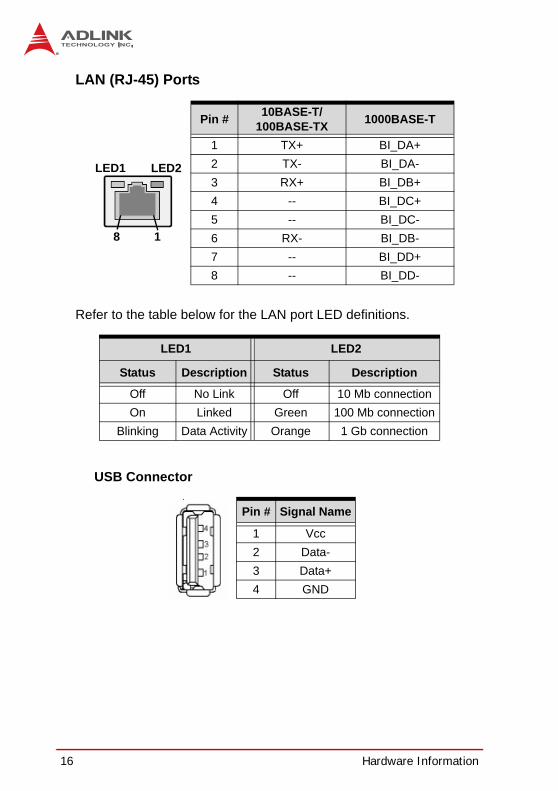
LAN (RJ-45) Ports
Refer to the table below for the LAN port LED definitions.
USB Connector
Pin # 10BASE-T/100BASE-TX 1000BASE-T
1 TX+ BI_DA+2 TX- BI_DA-3 RX+ BI_DB+4 -- BI_DC+5 -- BI_DC-6 RX- BI_DB-7 -- BI_DD+8 -- BI_DD-
LED1 LED2
Status Description Status Description
Off No Link Off 10 Mb connectionOn Linked Green 100 Mb connection
Blinking Data Activity Orange 1 Gb connection
Pin # Signal Name
1 Vcc2 Data-3 Data+4 GND
LED2LED1
18

Hardware Information 17
NuPRO-A331
VGA Port
Pin # Signal
1 Red2 Green3 Blue4 NC5 Ground6 Ground7 Ground8 Ground9 +5 V10 Ground11 NC12 DDC DAT13 HSYNC14 VSYNC15 DDC CLK

18 Hardware Information
2.2 Board Layout
Figure 2-2: Connectors and Jumpers
Connector Description1 CN1 ATX 12V Power connector2 DIMM1/2 DDR3 DIMM slots3 FAN1 FAN1 connector4 FAN2 FAN2 connector5 CN27 System Panel pin header6 CN7/8/11/12/28/29 SATA connectors7 CN2 DVI-D onboard connector8 CN18/17/14/13 COM3/4/5/6 connector9 CN26 Audio connector
10 CN10 COM2 connector11 CN6 COM1 connector12 CN5 Parallel Port connector13 JP8-11 COM2 mode jumpers14 JP1-4 COM1 mode jumpers15 JP6 PCIe Mini Card VGA pin header16 CN19/20/21 USB connectors17 CN4 Keyboard/Mouse pin header18 JBAT1 Clear CMOS19 SLOT1 PCIe Mini Card slot
3 42 6 7
17
5
13
15
8 9 10 11 12
16
18 19
14
1
Hardware Information 19
NuPRO-A331
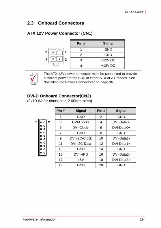
2.3 Onboard Connectors
ATX 12V Power Connector (CN1)
DVI-D Onboard Connector(CN2)(2x10 Wafer connector, 2.00mm pitch)
Pin # Signal
1 GND2 GND3 +12V DC4 +12V DC
NOTE:NOTE:
The ATX 12V power connector must be connected to provide sufficient power to the SBC in either ATX or AT modes. See “Installing the Power Connectors” on page 36.
Pin # Signal Pin # Signal
1 GND 2 GND3 DVI-Clock+ 4 DVI-Data0-5 DVI-Clock- 6 DVI-Data0+7 GND 8 GND9 DVI-I2C-Clock 10 DVI-Data1-11 DVI-I2C-Data 12 DVI-Data1+13 GND 14 GND15 DVI-HPD 16 DVI-Data2-17 +5V 18 DVI-Data2+19 GND 20 GND
1
3
2
4
1 2

20 Hardware Information
DVI-D Bracket Connector(optional cable w/ bracket, P/N 30-01052-2000)
PS/2 Keyboard/Mouse Pin Header (CN4)(2x3 pin header, 2.54mm pitch)
Pin # Signal Pin # Signal
1 TMDS Data2- 13 TMDS Data3+2 TMDS Data2+ 14 +5 V Power3 TMDS Data2/4 Shield 15 GND4 TMDS Data4- 16 Hot Plug Detect5 TMDS Data4+ 17 TMDS Data0-6 DDC Clock [SCL] 18 TMDSData0+7 DDC Data [SDA] 19 TMDS Data0/5 Shield8 Analog vertical sync 20 TMDS Data5-9 TMDS Data1- 21 TMDS Data5+10 TMDS Data1+ 22 TMDS Clock Shield11 TMDS Data1/3 Shield 23 TMDS Clock +12 TMDS Data3- 24 TMDS Clock -
Pin # Signal Pin # Signal
1 KBDATA 2 KBCLK3 MSDATA 4 MSCLK5 KM_VCC 6 GND
1 2

Hardware Information 21
NuPRO-A331
PS/2 Keyboard/Mouse Bracket Connectors(optional cable w/ bracket, P/N: 30-01019-2000)
PS/2 Mouse Port (green)
PS/2 Keyboard Port (purple)
Pin # Signal Function
1 MSDATA Mouse Data2 NC not connected3 GND Ground4 +5V Power5 CLK Clock6 NC not connected
Pin # Signal Function
1 KBDATA Keyboard Data2 NC not connected3 GND Ground4 +5V Power5 CLK Clock6 NC not connected
22 Hardware Information
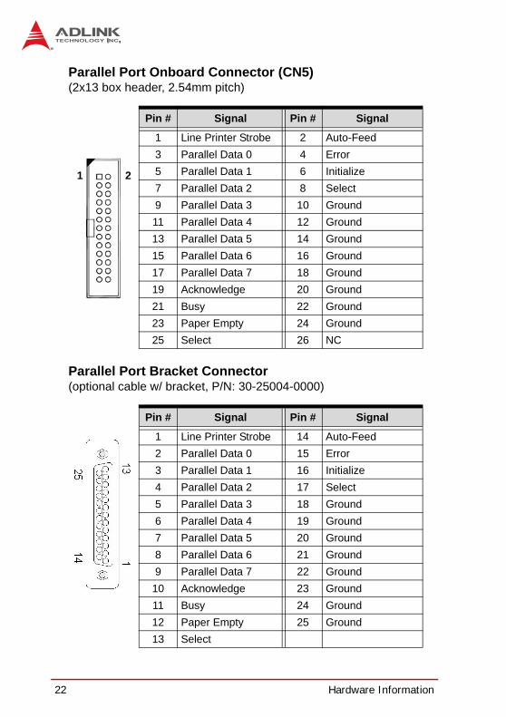
Parallel Port Onboard Connector (CN5)(2x13 box header, 2.54mm pitch)
Parallel Port Bracket Connector(optional cable w/ bracket, P/N: 30-25004-0000)
Pin # Signal Pin # Signal
1 Line Printer Strobe 2 Auto-Feed3 Parallel Data 0 4 Error5 Parallel Data 1 6 Initialize7 Parallel Data 2 8 Select9 Parallel Data 3 10 Ground11 Parallel Data 4 12 Ground13 Parallel Data 5 14 Ground15 Parallel Data 6 16 Ground17 Parallel Data 7 18 Ground19 Acknowledge 20 Ground21 Busy 22 Ground23 Paper Empty 24 Ground25 Select 26 NC
Pin # Signal Pin # Signal
1 Line Printer Strobe 14 Auto-Feed2 Parallel Data 0 15 Error3 Parallel Data 1 16 Initialize4 Parallel Data 2 17 Select5 Parallel Data 3 18 Ground6 Parallel Data 4 19 Ground7 Parallel Data 5 20 Ground8 Parallel Data 6 21 Ground9 Parallel Data 7 22 Ground
10 Acknowledge 23 Ground11 Busy 24 Ground12 Paper Empty 25 Ground13 Select
1 2
Hardware Information 23
NuPRO-A331
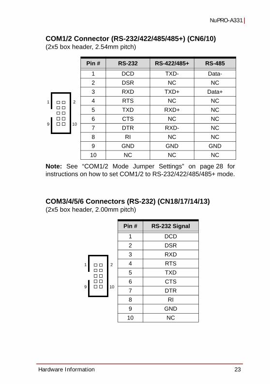
COM1/2 Connector (RS-232/422/485/485+) (CN6/10)(2x5 box header, 2.54mm pitch)
Note: See “COM1/2 Mode Jumper Settings” on page 28 forinstructions on how to set COM1/2 to RS-232/422/485/485+ mode.
COM3/4/5/6 Connectors (RS-232) (CN18/17/14/13)(2x5 box header, 2.00mm pitch)
Pin # RS-232 RS-422/485+ RS-485
1 DCD TXD- Data-2 DSR NC NC3 RXD TXD+ Data+4 RTS NC NC5 TXD RXD+ NC6 CTS NC NC7 DTR RXD- NC8 RI NC NC9 GND GND GND10 NC NC NC
Pin # RS-232 Signal
1 DCD2 DSR3 RXD4 RTS5 TXD6 CTS7 DTR8 RI9 GND
10 NC
1 2
9 10
1 2
9 10

24 Hardware Information
COM Bracket Connectors(cables w/ bracket supplied with the NuPRO-A331 - DB9 connector)
Serial ATA Connectors (CN7/8/11/12/28/29)(7P L-connector, 1.27mm pitch)
USB 2.0 Connectors (CN19/20/21)(2x5 box header, 2.54mm pitch)
Pin # RS-232 RS422/485+ RS485
1 DCD TXD- Data-2 RXD TXD+ Data+3 TXD RXD+ --4 DTR RXD --5 GND GND GND 6 DSR -- --7 RTS -- --8 CTS -- --9 RI -- --
Pin # Signal
1 GND2 TXP3 TXN4 GND5 RXN6 RXP7 GND
Pin # Signal Pin # Signal
1 +5V 2 +5V3 USB0- 4 USB1-5 USB0+ 6 USB1+7 GND 8 GND9 Key 10 NC
1
5
6
1
7

Hardware Information 25
NuPRO-A331
HD Audio Daughter Board Connector (CN26)(2x5 box header, 2.54mm pitch)
This connector is designed for use with the ADLINK DB-Audio2daughter board.
Pin # Signal Function
1 GND Ground2 AUD_BCLK Audio Clock3 GND Ground4 ICH_AUD_SDIN1 Audio Data Input5 P5V + 5V6 ICH_AUD_SDOUT Audio Data Output7 P5V_AUD + 5V8 P3V3_DVDD 3.3V9 AUD_SYNC Audio Synchronous10 AUD_RSTJ Audio Reset
1 2
9 10
26 Hardware Information
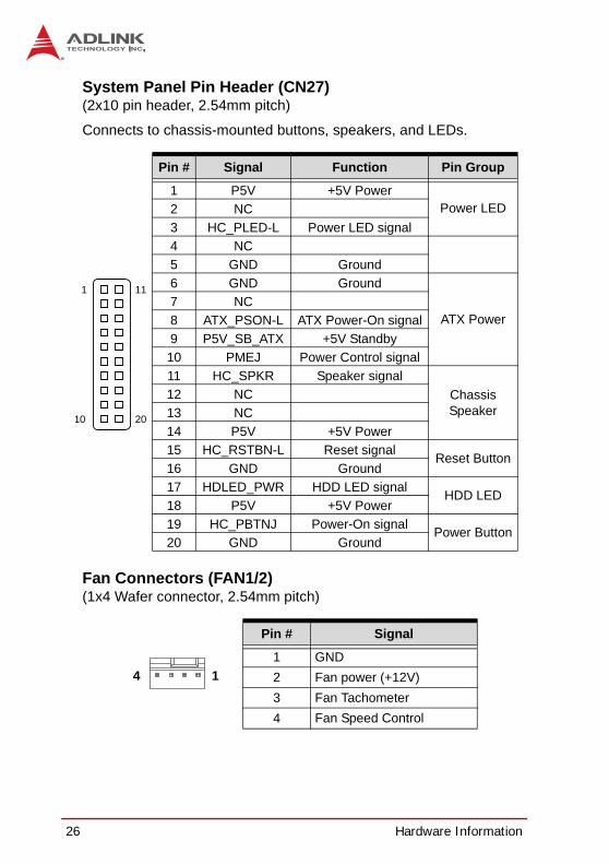
System Panel Pin Header (CN27)(2x10 pin header, 2.54mm pitch)
Connects to chassis-mounted buttons, speakers, and LEDs.
Fan Connectors (FAN1/2)(1x4 Wafer connector, 2.54mm pitch)
Pin # Signal Function Pin Group
1 P5V +5V PowerPower LED2 NC
3 HC_PLED-L Power LED signal4 NC5 GND Ground6 GND Ground
ATX Power7 NC8 ATX_PSON-L ATX Power-On signal9 P5V_SB_ATX +5V Standby10 PMEJ Power Control signal11 HC_SPKR Speaker signal
Chassis Speaker
12 NC13 NC14 P5V +5V Power15 HC_RSTBN-L Reset signal Reset Button16 GND Ground17 HDLED_PWR HDD LED signal HDD LED18 P5V +5V Power19 HC_PBTNJ Power-On signal Power Button20 GND Ground
Pin # Signal
1 GND2 Fan power (+12V)3 Fan Tachometer4 Fan Speed Control
1
10 20
11
14

Hardware Information 27
NuPRO-A331
PCIe Mini Card VGA Pin Header(JP6)(2x7 pin header, 2.00mm pitch)
This header is connected to the optional mPCIe-8770 to providegraphics output to the VGA connector on the rear panel.
Pin # Signal Pin # Signal
1 NC 2 CRTDAT3 NC 4 CRTCLK5 GND 6 CRTR7 GND 8 CRTG9 GND 10 CRTB11 GND 12 CRTHS13 GND 14 CRTVS
1 2

28 Hardware Information
2.4 JumpersClear CMOS (JBAT1)The CMOS RAM data contains the date/time and BIOS settinginformation. CMOS is powered by the onboard button cell battery.To erase the CMOS RAM data:
1. Power down and disconnect power from the system.
2. Short pins 2-3 on JP1.
3. Reconnect power and power up the system.
4. After power up, remove the jumper cap from pins 2-3and reinstall it to pins 1-2.
COM1/2 Mode Jumper SettingsShort the jumper pins according to the following settings to setCOM1/2 to RS-232/422/485/485+ mode.
COM1 (JP1-4)
COM2 (JP8-11)
RTC status Connection JBAT1
Normal 1 – 2
Clear CMOS 2 – 3
RS-232 RS-422 RS-485 RS-485+
JP1 - 1-3, 2-4 1-3, 2-4 3-5, 4-6JP2 1-3, 2-4 3-5, 4-6 3-5, 4-6 3-5, 4-6JP3 1-3, 2-4 3-5, 4-6 3-5, 4-6 3-5, 4-6JP4 1-2 3-4 5-6 5-6
RS-232 RS-422 RS-485 RS-485+
JP11 - 1-3, 2-4 1-3, 2-4 3-5, 4-6JP9 1-3, 2-4 3-5, 4-6 3-5, 4-6 3-5, 4-6
JP10 1-3, 2-4 3-5, 4-6 3-5, 4-6 3-5, 4-6JP8 1-2 3-4 5-6 5-6
Getting Started 29
NuPRO-A331
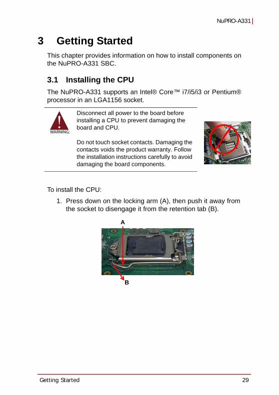
3 Getting StartedThis chapter provides information on how to install components onthe NuPRO-A331 SBC.
3.1 Installing the CPUThe NuPRO-A331 supports an Intel® Core™ i7/i5/i3 or Pentium®processor in an LGA1156 socket.
To install the CPU:
1. Press down on the locking arm (A), then push it away fromthe socket to disengage it from the retention tab (B).
WARNING:
Disconnect all power to the board before installing a CPU to prevent damaging the board and CPU.
Do not touch socket contacts. Damaging the contacts voids the product warranty. Follow the installation instructions carefully to avoid damaging the board components.
A
B

30 Getting Started
2. Raise the locking arm to unlock the load plate.
3. Lift the load plate to uncover the socket.
4. Remove the plastic protective cover from the socket.Note the locations of the alignment keys (A) and Pin 1indicator (B).
WARNING:
DO NOT touch socket contacts.
AB

Getting Started 31
NuPRO-A331
5. Hold the CPU using thumb and forefinger as shown.Position the CPU over the socket, matching the notcheson the sides of the CPU with the alignment keys on thesocket (A). The golden triangle on the CPU must bepositioned at the corner of the socket with the Pin 1 indi-cator as shown (B).
6. Carefully place the CPU into the socket vertically. Thesocket has cutouts for your fingers to fit into.
WARNING:
The CPU fits into the socket in only one orientation. DO NOT force it into the socket to avoid causing damage.
AB
Cutouts
32 Getting Started
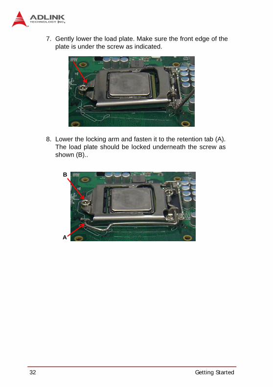
7. Gently lower the load plate. Make sure the front edge of theplate is under the screw as indicated.
8. Lower the locking arm and fasten it to the retention tab (A).The load plate should be locked underneath the screw asshown (B)..
A
B

Getting Started 33
NuPRO-A331
3.2 Installing the CPU Fan and Heatsink
When the CPU fan installation procedures presented here areinconsistent with the installation procedures you obtained from theCPU fan and heatsink package, follow the latter.
To install the CPU fan:
1. Apply thermal grease evenly on top of the installed CPU.
2. Lower the CPU fan to the CPU, then secure it using theprovided attachments or screws.
3. Connect the CPU fan cable to the CPU fan connector onthe SBC labeled FAN1 (see “Board Layout” on page 18).
CAUTION:
The CPU requires a chassis with an airflow inlet and maximum internal ambient temperature of 60° C. An approved CPU heat-sink and fan must be installed before using the SBC. Failure to install a CPU fan and heatsink may damage the system host board and/or the CPU.

34 Getting Started
3.3 Installing Memory ModulesThe NuPRO-A331 supports up to 8 GB of DDR3 1066/1333 MHzmemory modules in two DIMM sockets. A DDR3 module has a240-pin footprint compared to the legacy 184-pin DDR DIMM.DDR3 modules are notched to facilitate correct installation in theDIMM sockets.
Memory Configuration OptionsThe NuPRO-A331 supports 1GB, 2GB and 4GB unbuffered non-ECC DDR3 DIMMs in the following configurations:
Channel A: DIMM1Channel B: DIMM2For dual-channel configuration, the total size of memory module installed per channel must be the same(DIMM1 = DIMM2).It is recommended that you install DIMMs with the same CAS latency. For maximum compatibility, install memory modules with the same brand, model, and/or rating.
To install a memory module:
1. Locate the DIMM sockets on the motherboard.
2. Press the socket’s retaining clips outward to unlock.
WARNING:
Disconnect all power to the board before installing a memory module to prevent damaging the board and memory module .
Getting Started 35
NuPRO-A331
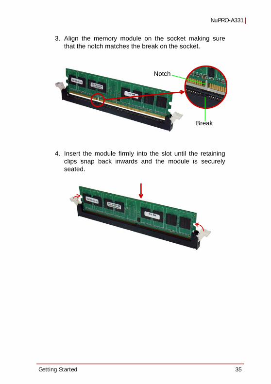
3. Align the memory module on the socket making surethat the notch matches the break on the socket.
4. Insert the module firmly into the slot until the retainingclips snap back inwards and the module is securelyseated.
Break
Notch

36 Getting Started
3.4 Installing the Power ConnectorsRefer to Section 2.2 Board Layout on page 18 and Section 2.3Onboard Connectors on page 19 for detailed information on con-nectors and pin definitions referred to below.
ATX 12V Power ConnectorThe NuPRO-A331 requires +12V DC power connected to CN1 forproper operation in either ATX or AT modes. If necessary, order aATX12V Convert Cable from ADLINK for use with Molex 4-pinpower connectors (P/N 30-00006-0000).
Front Panel ConnectorBefore powering up the NuPRO-A331, connect the necessary sig-nals from the backplane to the System Panel pin header (CN27).The ATX Power Connector pin group (pins 6, 8, 9, 10) and PowerButton pin group (pins 19, 20) must be connected for the systemto power up in ATX mode.

Driver Installation 37
NuPRO-A331
4 Driver InstallationThis chapter provides information on how to install theNuPRO-A331 device drivers under Windows XP 32-bit. Thedevice drivers are located in the following ADLINK All-in-One DVDdirectories:
Install the Windows operating system before installing any driver.Most standard I/O device drivers are installed during Windowsinstallation.
4.1 Intel® Rapid Storage Technology Driver1. Create a floppy image as described in the F6Readme.txt file
contained in X:\NuPRO\NuPRO-A331\Others\F6_SATA_Floppy_Install_Image_9.6.0.1014_Windows7_XP_32.zip.
2. During Windows installation, press F6 when you see the message “Press F6 if you need to install a third party SCSI or RAID driver.” Then press S to Specify Additional Device.
3. Insert the floppy disk and follow the remaining instruc-tions. Leave the disk in until the system has rebooted and copied the necessary files, then remove the disk.
Chipset \NuPRO\NuPRO-A331\Chipset\Display \NuPRO\NuPRO-A331\VGA\
\Add-On Card\mPCIe-8770\Ethernet \NuPRO\NuPRO-A331\Ethernet\TPM \NuPRO\NuPRO-A331\TPM\.Net Framework \NuPRO\NuPRO-A331\Others\Rapid Storage \NuPRO\NuPRO-A331\Others\ISA \NuPRO\NuPRO-A331\ISAAudio \Audio Daughter Board\DB-Audio2\
NOTE:NOTE:
In order to enable RAID or AHCI mode, you must pre-install the Intel® Rapid Storage Technology driver during the Windows instal-lation process. using the F6 installation method.

38 Driver Installation
4.2 Intel® Q57 Express Chipset DriverThis section describes the installation of the Intel® Q57 Expresschipset driver.
1. Locate the directory X:\NuPRO\NuPRO-A331\Chipset\ on the ADLINK All-in-One DVD, and extract the contents of the following archive: Intel Chipset Device Software_All OS_9.1.2.1007.zip.
2. Run the program setup.exe and follow the onscreen instructions. Restart the system if prompted.
4.3 Display DriverIntegrated Intel® HD GraphicsThis section describes the driver installation for the IntegratedIntel® HD Graphics on dual core 32nm (Clarkdale) processors.
Before installing the graphics driver, first install Microsoft .NETFramework 3.5 SP1 (not required for Windows 7).
1. Locate the directory X:\NuPRO\NuPRO-A331\Others\ on the ADLINK All-in-One DVD, and extract the contents of the follow-ing archive: Microsoft_Net_Framework_v3.5_SP1.zip
2. Run the program Microsoft_Net_Framework_v3.5_SP1.exe and follow the onscreen instructions.Restart the system if prompted.
Follow these instructions to install the graphics driver:
1. Locate the directory X:\NuPRO\NuPRO-A331\VGA\ on the ADLINK All-in-One DVD, and extract the contents of the follow-ing archive:Intel_ Graphics Driver_6.14.10.5268_Windows XP_32.zip.
2. Run the program setup.exe and follow the onscreen instructions. Restart the system if prompted.

Driver Installation 39
NuPRO-A331
mPCIe-8770 Graphics CardThis section describes the driver installation for the mPCIe-8770graphics card.
Follow these instructions to install the display driver:
1. Locate the directory X:\NuPRO\NuPRO-A331\Add-On Card\mPCIe-8770\ on the ADLINK All-in-One DVD, and extract the contents of the follow-ing archive: mPCIe-8770_VGA_driver_Z11_All_WinOS_v6.14.10.1130.zip.
2. Run the program xgirun.exe and follow the onscreen instructions. Restart the system if prompted.
4.4 Ethernet DriverFollow these instructions to install the Ethernet driver.
1. Locate the directory X:\NuPRO\NuPRO-A331\Ethernet\ on the ADLINK All-in-One DVD, and extract the contents of the following archive: Network Adapter Driver_15.4.1_Windows XP_32.zip.
2. Run the program Network Adapter Driver_15.4.1_Windows XP_32.exe and follow the onscreen instructions. Restart the system if prompted.
4.5 Intel® Rapid Storage Technology UtilityFollow these instructions to install the Intel® Rapid Storage Technology utility.
1. Locate the directory X:\NuPRO\NuPRO-A331\Others\ on the ADLINK All-in-One DVD, and extract the file the contents from the following archive: Intel_Rapid_Storage_Technology_All_WinOS_v9.6.0.1014.zip.
2. Run the program Intel_Rapid_Storage_Technology_All_WinOS_9.6.0.1014.exe and follow the onscreen instructions. Restart the system if prompted.

40 Driver Installation
4.6 TPM DriverFollow these instructions to install the TPM driver (not required forWindows 7).
1. Locate the directory X:\NuPRO\NuPRO-A331\TPM\ on the ADLINK All-in-One DVD, and extract the contents of the following archive: ST_TPM_All_WinOS_v3.5.SP1.zip.
2. Run the program \win32\setup.exe and follow the onscreen instructions. Restart the system if prompted.
4.7 ISA DriverFollow these instructions to install the ISA driver (not required forWindows 7).
1. Open the Device Manager on your system.
2. Right click on ‘Other PCI Bridge Devices’.
3. A dialog box will appear. Select ‘Update Driver...’4. The ‘Hardware Update Wizard’ dialog box will open.
Read the instructions and then click option 3, ‘No, notthis time’, then click ‘Next’ to continue.
5. The next screen will prompt you to search for the loca-tion of the driver for your device. Click option 2, ‘Installfrom a list or specific location (Advanced)’ and thenclick ‘Next’.
6. Locate the following folder on the ADLINK All-in-OneDVD: X:\NuPRO\NuPRO-A331\ISA. Press ‘Next’ toinstall the ite.inf file.
7. After successfully installing the files, the ‘HardwareUpdate Wizard’ will display the ‘Completing the Hard-ware Update Wizard’ screen. Click ‘Finish’.

Driver Installation 41
NuPRO-A331
4.8 Audio DriverFollow these instructions to install the audio driver for the optionalDB-Audio2 daughter board.
1. Place the ADLINK All-in-One DVD to the optical drive.
2. Locate the audio driver from the directory X:\Audio Daughter Board\DB-Audio2\, then dou-ble-click on the setup.exe file to start installation.
3. Follow the screen instructions to complete installation, then restart the system if prompted.
4.9 Management EngineAfter installing all required drivers, Windows Device Manager willshow one device without a driver: PCI Simple CommunicationsController. This device is the Intel Active Management Technol-ogy Management Engine. Intel Active Management Technology isnot supported by the NuPRO-A331, but the driver can be installedin order to remove the “question mark” from the Device Manager.
Follow these instructions to install the Intel® Active ManagementTechnology driver.
1. Locate the directory X:\NuPRO\NuPRO-A331\Others\ on the ADLINK All-in-One DVD, and extract the contents of the following archive: Intel_Management_Engine_Interface_SOL_driver_All_WinOS.zip.
2. Run the program \ME_Drivers\MEI_SOL_Installer\Setup.exe and follow the onscreen instructions. Restart the system if prompted.
NOTE:NOTE:
Before installing the audio driver, check the BIOS settings to make sure that audio is enabled: Chipset > PCH Configura-tion > HDA Controller (see “PCH Configuration” on page 70).

42 Driver Installation
This page intentionally left blank.

BIOS Setup 43
NuPRO-A331
5 BIOS SetupThe following chapter describes basic navigation for theAMIBIOS®8 BIOS setup utility.
5.1 Starting the BIOSTo enter the setup screen, follow these steps:
1. Power on the motherboard
2. Press the < Delete > key on your keyboard when yousee the following text prompt:< Press DEL to run Setup >
3. After you press the < Delete > key, the main BIOS setupmenu displays. You can access the other setup screensfrom the main BIOS setup menu, such as Chipset andPower menus.
Note: In most cases, the < Delete > key is used to invoke the setup screen. There are several cases that use other keys, such as < F1 >, < F2 >, and so on.
44 BIOS Setup
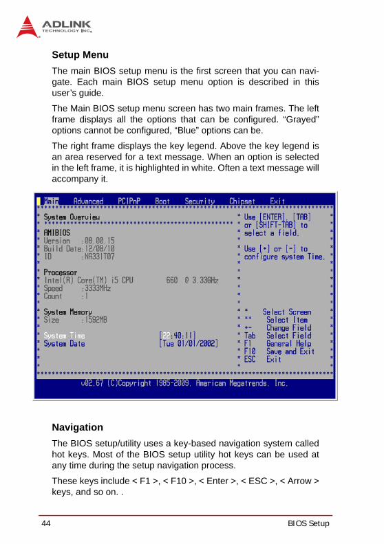
Setup MenuThe main BIOS setup menu is the first screen that you can navi-gate. Each main BIOS setup menu option is described in thisuser’s guide.
The Main BIOS setup menu screen has two main frames. The leftframe displays all the options that can be configured. “Grayed”options cannot be configured, “Blue” options can be.
The right frame displays the key legend. Above the key legend isan area reserved for a text message. When an option is selectedin the left frame, it is highlighted in white. Often a text message willaccompany it.
NavigationThe BIOS setup/utility uses a key-based navigation system calledhot keys. Most of the BIOS setup utility hot keys can be used atany time during the setup navigation process.
These keys include < F1 >, < F10 >, < Enter >, < ESC >, < Arrow >keys, and so on. .

BIOS Setup 45
NuPRO-A331
Note: There is a hot key legend located in the right frame on most setup screens.
The < F8 > key on your keyboard is the Fail-Safe key. It is not dis-played on the key legend by default. To set the Fail-Safe settingsof the BIOS, press the < F8 > key on your keyboard. It is locatedon the upper row of a standard 101 keyboard. The Fail-Safe set-tings allow the motherboard to boot up with the least amount ofoptions set. This can lessen the probability of conflicting settings.
Hotkey DescriptionsF1 The < F1 > key allows you to display the General Help
screen.
Press the < F1 > key to open the General Help screen.

46 BIOS Setup
F10 The < F10 > key allows you to save any changes you have made and exit Setup. Press the < F10 > key to save your changes. The following screen will appear:
Press the < Enter > key to save the configuration and exit. You can also use the < Arrow > key to select Cancel and then press the < Enter > key to abort this function and return to the previous screen.
ESC The < Esc > key allows you to discard any changes you have made and exit the Setup. Press the < Esc > key to exit the setup without saving your changes. The following screen will appear:
Press the < Enter > key to discard changes and exit. You can also use the < Arrow > key to select Cancel and then press the < Enter > key to abort this function and return to the pre-vious screen.
Enter The < Enter > key allows you to display or change the setup option listed for a particular setup item. The < Enter > key can also allow you to display the setup sub-screens.

BIOS Setup 47
NuPRO-A331
5.2 Main SetupWhen you first enter the Setup Utility, you will enter the Main setupscreen. You can always return to the Main setup screen by select-ing the Main tab. There are two Main Setup options. They aredescribed in this section. The Main BIOS Setup screen is shownbelow.
System Time/System DateUse this option to change the system time and date. Highlight Sys-tem Time or System Date using the < Arrow > keys. Enter new val-ues using the keyboard. Press the < Tab > key or the < Arrow >keys to move between fields. The date must be entered in MM/DD/YY format. The time is entered in HH:MM:SS format.
Note: The time is in 24-hour format. For example, 5:30 A.M. ap-pears as 05:30:00, and 5:30 P.M. as 17:30:00.

48 BIOS Setup
5.3 Advanced BIOS SetupSelect the Advanced tab from the setup screen to enter theAdvanced BIOS Setup screen. You can select any of the items inthe left frame of the screen, such as SuperIO Configuration, to goto the submenu for that item. You can display an Advanced BIOSSetup option by highlighting it using the < Arrow > keys. TheAdvanced BIOS Setup screen is shown below.
The sub-menus are described on the following pages.

BIOS Setup 49
NuPRO-A331
5.3.1 CPU Configuration
Intel® Virtualization TechWhen enabled, Intel® Virtualization Technology (Intel® VT)makes a single system appear as multiple independent sys-tems to software. This allows for multiple, independent operat-ing systems to be running simultaneously on a single system.
Intel® C-STATE TechC-states are processor power states within the S0 system statethat provide for various levels of power savings.
Intel® SpeedStep™ TechThis option allows you to enable or disable Intel® SpeedStepTechnology.

50 BIOS Setup
5.3.2 IDE Configuration
Configure SATA asOptions: IDE, RAID, AHCI, Disabled
SATA#1 IDE ConfigurationWhen running in Compatible mode, SATA channels 1, 2, 3 and4 can be configured as legacy IDE channels.
SATA#2 IDE ConfigurationWhen running at compatible mode, SATA channels 5 and 6 canbe configured as legacy IDE channels.
IDE Master/SlaveSelect one of the hard disk drives to configure it. Press< Enter > to access its submenu.

BIOS Setup 51
NuPRO-A331
5.3.3 Super IO Configuration
Serial Port1-6 Address/IRQSpecifies the serial port addresses. The options are:
Port1-2: 3F8, 2F8, 3E8, 2E8, DisabledPort3-6: 3F8, 2F8, 3E8, 2E8, 2F0, 2E0, Disabled
IRQ settings are fixed as shown.
Parallel Port Address/IRQThis option specifies the base I/O port address and IRQ of theparallel port.

52 BIOS Setup
5.3.4 Hardware Health ConfigurationThis option displays the current status of all of the monitored hard-ware devices/components such as voltages and temperatures.The options are Enabled and Disabled.
H/W Health FunctionSelect this option to enable or disable the BIOS Hardware HealthMonitoring Device.
Fan 1/2 Mode SettingThree modes are provided for each fan: Full On mode, Automaticmode, and PWM Manually mode. Full On mode runs the fan at fullspeed. Automatic mode is Smart Fan mode. PWM Manually moderuns the fan at the set speed.
Full On Mode

BIOS Setup 53
NuPRO-A331
Automatic Mode
Temperature 1 Limit of OFFWhen the temperature (°C) is higher than the set value, Fan1/2will run at Start PWM speed. When the temperature is lowerthan the set value, Fan1/2 will stop.
Temperature 1 Limit of StartWhen the temperature (°C) is higher than the set value, Fan1/2will increase its speed by Slope PWM 1 value.
Fan 1/2 Start PWMSets a value to control the fan speed between Limit of OFF andLimit of Start. Minimum is 0 and Maximum is 127.
Slope PWM 1/2The Slope PWM Value sets the rate of increase the fan speedwhen the temperature is above Limit of Start.

54 BIOS Setup
PWM Manually Mode
Fan 1/2 PWM ControlSets a value to control the fan speed. Minimum is 0 and Maxi-mum is 127.

BIOS Setup 55
NuPRO-A331
5.3.5 ACPI Settings
ACPI OS Shutdown ModeThis option sets the OS shutdown mode to ATX or AT. ATX: OSwill turn off system power when shutdown. AT: OS will display“It is now safe to turn off your computer."

56 BIOS Setup
5.3.6 AHCI ConfigurationYou can use this screen to select options for the AHCI Settings.Use the up and down < Arrow > keys to select an item. Use the <+ > and < - > keys to change the value of the selected option.
BIOS Setup 57
NuPRO-A331
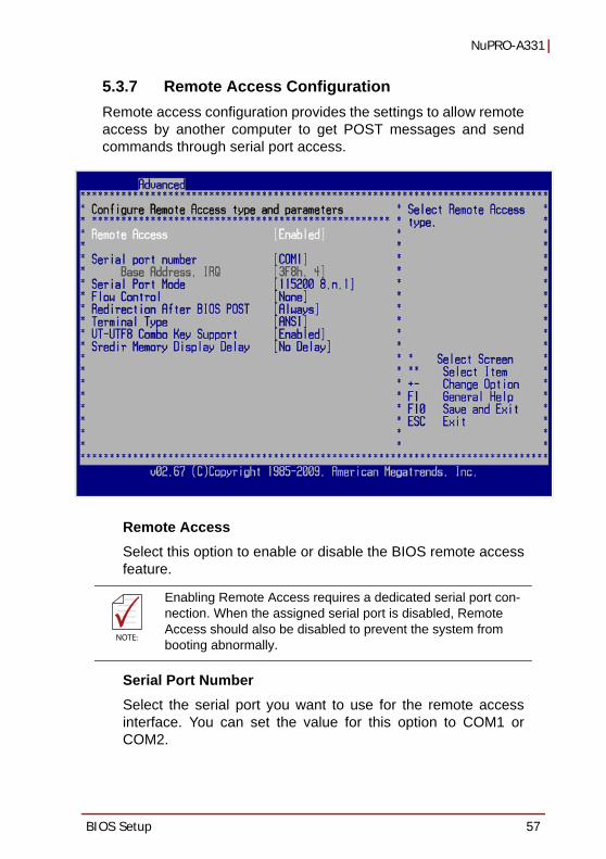
5.3.7 Remote Access ConfigurationRemote access configuration provides the settings to allow remoteaccess by another computer to get POST messages and sendcommands through serial port access.
Remote AccessSelect this option to enable or disable the BIOS remote accessfeature.
Serial Port NumberSelect the serial port you want to use for the remote accessinterface. You can set the value for this option to COM1 orCOM2.
NOTE:NOTE:
Enabling Remote Access requires a dedicated serial port con-nection. When the assigned serial port is disabled, Remote Access should also be disabled to prevent the system from booting abnormally.

58 BIOS Setup
Serial Port ModeSelect the baud rate you want the serial port to use for consoleredirection. The options are 115200 8,n,1; 57600 8,n,1;19200 8,n,1; and 09600 8,n,1.
Flow ControlSet this option to select Flow Control for console redirection.The settings for this value are None, Hardware, or Software.
Redirection After BIOS POSTThis option allows you to set Redirection configuration afterBIOS POST. The settings for this value are Disabled, BootLoader, or Always.
Disabled: Set this value to turn off the redirection after POSTBoot Loader: Set this value to allow the redirection to be active during POST and Boot Loader.Always: Set this value to allow the redirection to be always active.
Terminal TypeThis option is used to select either VT100/VT-UTF8 or ANSIterminal type. The settings for this value are ANSI, VT100, orVT-UTF8.
VT-UTF8 Combo Key SupportThis option enables VT-UTF8 Combination Key Support forANSI/VT100 terminals. The settings for this value are Enabledor Disabled.
Sredir Memory Display DelayThis option gives the delay in seconds to display memory infor-mation. The options for this value are No Delay, Delay 1 Sec,Delay 2 Sec, or Delay 4 Sec.

BIOS Setup 59
NuPRO-A331
5.3.8 Trusted ComputingTrusted computing is an industry standard to make personal com-puters more secure through a dedicated hardware chip, called aTrusted Platform Module (TPM). This submenu provides allowsyou to enable/disable, execute and clear the TPM.

60 BIOS Setup
5.3.9 USB Configuration
Legacy USB SupportLegacy USB Support refers to USB mouse and keyboard sup-port. Normally if this option is not enabled, any attached USBmouse or USB keyboard will not become available until a USBcompatible operating system is fully booted with all USB driv-ers loaded. When this option is enabled, any attached USBmouse or USB keyboard can control the system even whenthere are no USB drivers loaded on the system. Set this valueto enable or disable the Legacy USB Support.
Disabled: Set this value to prevent the use of any USB device in DOS or during system boot. Enabled: Set this value to allow the use of USB devices during boot and while using DOS. Auto: This option auto detects USB Keyboards or Mice and if found, allows them to be utilized during boot and while using DOS.

BIOS Setup 61
NuPRO-A331
USB 2.0 Controller ModeThe USB 2.0 Controller Mode configures the data rate of theUSB port. The options are FullSpeed (12 Mbps) and HiSpeed(480 Mbps).
Legacy USB 1.1 HC SupportEnables/disables legacy USB 1.1 host controller support.
USB Mass Storage Device ConfigurationThis is a submenu for configuring the USB Mass Storage ClassDevices when BIOS finds they are in use on USB ports. Emula-tion Type can be set according to the type of attached USBmass storage device(s). If set to Auto, USB devices less than530MB will be emulated as Floppy and those greater than530MB will remain as hard drive. The Forced FDD option canbe used to force a hard disk type drive (such as a Zip drive) toboot as FDD.

62 BIOS Setup
5.4 PCI/PnP SettingsSelect the PCI/PnP tab from the setup screen to enter the Plugand Play BIOS Setup screen. You can display a Plug and PlayBIOS Setup option by highlighting it using the < Arrow > keys. ThePlug and Play BIOS Setup screen is shown below.
5.4.1 IRQ/DMASet this value to allow the IRQ settings to be modified. Available –This setting allows the specified IRQ/DMA to be used by a PCI/PnP device. Reserved – This setting allows the specified IRQ/DMA to be used by a legacy ISA device.
5.4.2 Enable ISA PnP ConfigurationThis option allows you to enable or disable the ISA PnP function.

BIOS Setup 63
NuPRO-A331
5.5 Boot SettingsSelect the Boot tab from the setup screen to enter the Boot BIOSSetup screen. You can select any of the items in the left frame ofthe screen, such as Boot Device Priority, to go to the submenu forthat item. You can display a Boot BIOS Setup option by highlight-ing it using the < Arrow > keys. The Boot Settings screen is shownbelow:
5.5.1 Boot Settings ConfigurationUse this screen to select options for the Boot Settings Configura-tion. Use the up and down <Arrow> keys to select an item. Use the<Plus> and <Minus> keys to change the value of the selectedoption. The settings are described on the following pages. Thescreen is shown below.

64 BIOS Setup
Quick BootEnabling this setting will cause the BIOS power-on self testroutine to skip some of its tests during bootup for faster systemboot.
Quiet BootWhen this feature is enabled, the BIOS will display the full-screen logo during the boot-up sequence, hiding normal POSTmessages.
When it is disabled, the BIOS will display the normal POSTmessages, instead of the full-screen logo.
BIOS Setup 65
NuPRO-A331
5.5.2 Boot Device PriorityThe items allow you to set the sequence of boot devices whereBIOS attempts to load the disk operating system. First press<Enter> to enter the sub-menu. Then you may use the arrowkeys to select the desired device, then press <+>, <-> or<PageUp>, <PageDown> key to move it up/down in the prioritylist.
5.5.3 Boot Device GroupsThe Boot devices are listed in groups by device type. Firstpress <Enter> to enter the sub-menu. Then you may use thearrow keys to select the desired device, then press <+>, <-> or<PageUp>, <PageDown> key to move it up/down in the prioritylist. Only the first device in each device group will be availablefor selection in the Boot Device Priority option.

66 BIOS Setup
5.6 Security Setup
Password Support
Two Levels of Password ProtectionProvides both a Supervisor and a User password. If you useboth passwords, the Supervisor password must be set first.
The system can be configured so that all users must enter apassword every time the system boots or when Setup is exe-cuted, using either or either the Supervisor password or Userpassword.
The Supervisor and User passwords activate two different lev-els of password security. If you select password support, youare prompted for a one to six character password. Type thepassword on the keyboard. The password does not appear onthe screen when typed. Make sure you write it down. If you for-get it, you must drain NVRAM and re-configure.

BIOS Setup 67
NuPRO-A331
Remember the PasswordKeep a record of the new password when the password ischanged. If you forget the password, you must erase the sys-tem configuration information in NVRAM.
To access the submenu for the following items, select the itemand press < Enter >:
Change Supervisor PasswordChange User PasswordClear User Password
Supervisor PasswordIndicates whether a supervisor password has been set.
User PasswordIndicates whether a user password has been set.
Change Supervisor PasswordSelect this option and press < Enter > to access the submenu. Youcan use the submenu to change the supervisor password.
Change User PasswordSelect this option and press < Enter > to access the submenu. Youcan use the submenu to change the user password.
68 BIOS Setup
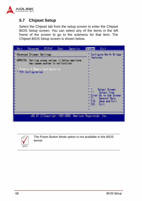
5.7 Chipset SetupSelect the Chipset tab from the setup screen to enter the ChipsetBIOS Setup screen. You can select any of the items in the leftframe of the screen to go to the submenu for that item. TheChipset BIOS Setup screen is shown below.
NOTE:NOTE:
The Power Button Mode option is not available in this BIOS kernel.

BIOS Setup 69
NuPRO-A331
5.7.1 Graphics and Memory Configuration
Initial Graphics AdapterSelect which graphics controller to use as the primary bootdevice. (“PCI” includes PCI slot and and PCIe Mini Card. PCIwill be first.)
IGD: Integrated graphics only.PCI/IGD: Detect PCI graphics first, then integrated graphics
IGD Graphics Mode SelectSelects the amount of system memory used by the integratedgraphics device.
Boot Display DeviceThis item allows the user to configuration the type of externaldisplay used during boot up.
CRT: VGA display only during POST and DOS.DVI: DVI display only during POST and DOS.CRT+DVI: VGA and DVI display during POST and DOS.
70 BIOS Setup
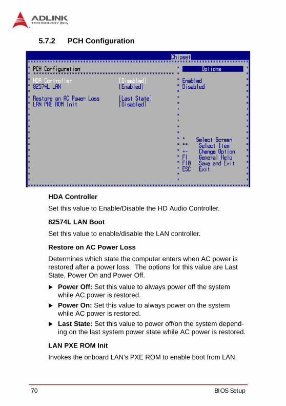
5.7.2 PCH Configuration
HDA ControllerSet this value to Enable/Disable the HD Audio Controller.
82574L LAN BootSet this value to enable/disable the LAN controller.
Restore on AC Power LossDetermines which state the computer enters when AC power isrestored after a power loss. The options for this value are LastState, Power On and Power Off.
Power Off: Set this value to always power off the system while AC power is restored.Power On: Set this value to always power on the system while AC power is restored. Last State: Set this value to power off/on the system depend-ing on the last system power state while AC power is restored.
LAN PXE ROM InitInvokes the onboard LAN’s PXE ROM to enable boot from LAN.

BIOS Setup 71
NuPRO-A331
5.8 Exit MenuSelect the Exit tab from the setup screen to enter the Exit BIOSSetup screen. You can display an Exit BIOS Setup option by high-lighting it using the < Arrow > keys. The Exit BIOS Setup screen isshown below.
Save Changes and ExitWhen you have completed the system configuration changes,select this option to leave Setup and reboot the computer so thenew system configuration parameters can take effect.
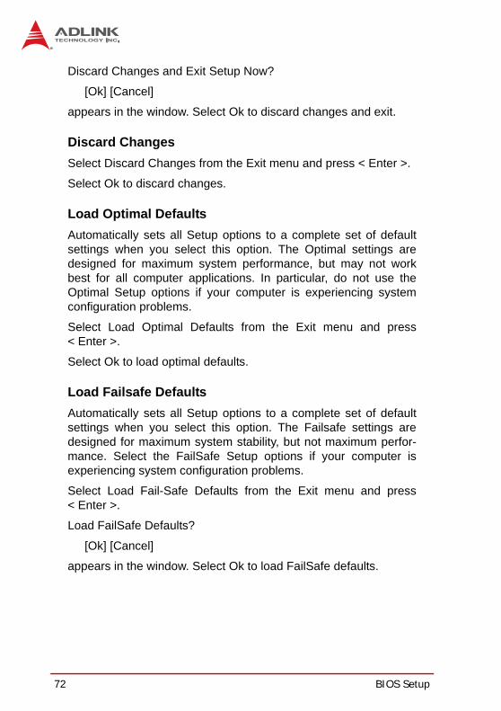
Save Configuration Changes and Exit Now?
[Ok] [Cancel]
appears in the window. Select Ok to save changes and exit.
Discard Changes and ExitSelect this option to quit Setup without making any permanentchanges to the system configuration.
72 BIOS Setup
Discard Changes and Exit Setup Now?
[Ok] [Cancel]
appears in the window. Select Ok to discard changes and exit.
Discard ChangesSelect Discard Changes from the Exit menu and press < Enter >.
Select Ok to discard changes.
Load Optimal DefaultsAutomatically sets all Setup options to a complete set of defaultsettings when you select this option. The Optimal settings aredesigned for maximum system performance, but may not workbest for all computer applications. In particular, do not use theOptimal Setup options if your computer is experiencing systemconfiguration problems.
Select Load Optimal Defaults from the Exit menu and press< Enter >.
Select Ok to load optimal defaults.
Load Failsafe DefaultsAutomatically sets all Setup options to a complete set of defaultsettings when you select this option. The Failsafe settings aredesigned for maximum system stability, but not maximum perfor-mance. Select the FailSafe Setup options if your computer isexperiencing system configuration problems.
Select Load Fail-Safe Defaults from the Exit menu and press< Enter >.
Load FailSafe Defaults?
[Ok] [Cancel]
appears in the window. Select Ok to load FailSafe defaults.

Watchdog Timer 73
NuPRO-A331
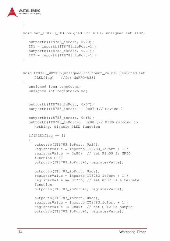
Appendix A - Watchdog TimerA sample program for configuring the NuPRO-A331’s watchdogtimer is included on the ADLINK All-in-One DVD in the followingdirectory: \NuPRO\NuPRO-A331\WDT.
A.1 Sample Code#include<stdio.h>#include<dos.h>
static unsigned int IT8783_ioPort = 0x2e;
void Enter_IT8783_Config(unsigned int flag){
if(flag) IT8783_ioPort = 0x4e;
switch(IT8783_ioPort){
case 0x2E: //Address port = 0x2E, enter keys = 0x87, 0x01, 0x55, 0x55
outportb(0x2E, 0x87);outportb(0x2E, 0x01);outportb(0x2E, 0x55);outportb(0x2E, 0x55);break;
case 0x4E: //Address port = 0x4E, enter keys = 0x87, 0x01, 0x55, 0xAA
outportb(0x4E, 0x87);outportb(0x4E, 0x01);outportb(0x4E, 0x55);outportb(0x4E, 0xAA);break;
default:break;
}}
void Exit_IT8783_Config(unsigned int flag){
if(flag) IT8783_ioPort = 0x4e;
outportb(IT8783_ioPort, 0x02);outportb(IT8783_ioPort+1, 0x02);
74 Watchdog Timer
}
void Get_IT8783_ID(unsigned int &ID1, unsigned int &ID2){
outportb(IT8783_ioPort, 0x20);ID1 = inportb(IT8783_ioPort+1);outportb(IT8783_ioPort, 0x21);ID2 = inportb(IT8783_ioPort+1);
}
void IT8783_WDTRun(unsigned int count_value, unsigned int PLEDflag) //for NuPRO-A331
{unsigned long tempCount;unsigned int registerValue;
outportb(IT8783_ioPort, 0x07);outportb(IT8783_ioPort+1, 0x07);// Device 7
outportb(IT8783_ioPort, 0xf8);outportb(IT8783_ioPort+1, 0x00);// PLED mapping to
nothing, disable PLED function
if(PLEDflag == 1){
outportb(IT8783_ioPort, 0x27);registerValue = inportb(IT8783_ioPort + 1);registerValue |= 0x80; // set Pin09 is GPIO function GP37outportb(IT8783_ioPort+1, registerValue);
outportb(IT8783_ioPort, 0xc2);registerValue = inportb(IT8783_ioPort + 1);registerValue &= 0x7fb; // set GP37 is alternate functionoutportb(IT8783_ioPort+1, registerValue);
outportb(IT8783_ioPort, 0xca);registerValue = inportb(IT8783_ioPort + 1);registerValue |= 0x80; // set GP42 is outputoutportb(IT8783_ioPort+1, registerValue);
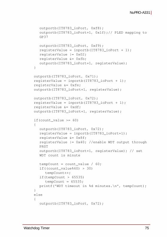
Watchdog Timer 75
NuPRO-A331
outportb(IT8783_ioPort, 0xf8);outportb(IT8783_ioPort+1, 0x1f);// PLED mapping to GP37
outportb(IT8783_ioPort, 0xf9);registerValue = inportb(IT8783_ioPort + 1);registerValue |= 0x02;registerValue &= 0xfb;outportb(IT8783_ioPort+1, registerValue);
}
outportb(IT8783_ioPort, 0x71);registerValue = inportb(IT8783_ioPort + 1);registerValue &= 0xfe; outportb(IT8783_ioPort+1, registerValue);
outportb(IT8783_ioPort, 0x72);registerValue = inportb(IT8783_ioPort + 1);registerValue &= 0xdf; outportb(IT8783_ioPort+1, registerValue);
if(count_value >= 60){
outportb(IT8783_ioPort, 0x72);registerValue = inportb(IT8783_ioPort+1);registerValue &= 0x8f; registerValue |= 0x40; //enable WDT output through PRSToutportb(IT8783_ioPort+1, registerValue); // set WDT count is minute
tempCount = count_value / 60;if((count_value%60) > 30)
tempCount++;if(tempCount > 65535)
tempCount = 65535;printf("WDT timeout in %d minutes.\n", tempCount);
}else{
outportb(IT8783_ioPort, 0x72);

76 Watchdog Timer
registerValue = inportb(IT8783_ioPort+1);registerValue |= 0x80;
tempCount = count_value;if(tempCount != 0){
printf("WDT timeout in %d seconds.\n", tempCount);
registerValue |= 0x40; //Enable WDT output through KBRST}else{
printf("WDT is Disabled.\n");registerValue &= 0xbf; //Disable WDT output
through KBRST}
outportb(IT8783_ioPort+1, registerValue); // set WDT count is second
}
outportb(IT8783_ioPort, 0x71);registerValue = inportb(IT8783_ioPort + 1);registerValue |= 0x60; // set Mouse & Keyboard
interrupt Enableoutportb(IT8783_ioPort+1, registerValue);
outportb(IT8783_ioPort, 0x73);outportb(IT8783_ioPort+1, tempCount); // set WDT count
LSB
}

System Resources 77
NuPRO-A331
Appendix B - System ResourcesB.1 System Memory Map
Table B-1: System Memory Map
B.2 Direct Memory Access Channels
Table B-2: Direct Memory Access Channels
Note (1): DMA channel 0/1/3 is selected when using parallel port.Floppy and parallel port cannot be used at the same time.
Address Range (decimal)
Address Range (hex) Size Description
(4GB-2MB) FFE00000 – FFFFFFFF 2 MB High BIOS Area
(4GB-18MB) – (4GB-17MB-1)
FEE00000 – FEEFFFFF 1 MB FSB Interrupt Memory Space
(4GB-20MB) – (4GB-19MB-1)
FEC00000 – FECFFFFF 1 MB APIC Configuration Space
960 K – 1024 K F0000 – FFFFF 64 KB System BIOS Area896 K – 960 K E0000 – EFFFF 64 KB Extended System BIOS Area
768 K – 896 K C0000 – DFFFF 128 KB
PCI expansion ROM areaC0000 – C7FFF: Onboard VGA BIOSCB800 – CC7FFF: Intel 82578DM PXE option ROM when onboard LAN boot ROM is enabled.
640 K – 768 K A0000 – BFFFF 128 KB Video Buffer & SMM space0 K – 640 K 00000 – 9FFFF 640 KB DOS Area
Channel Number Data Width System Resource
0 8-bits Parallel port(1)
1 8-bits Parallel port(1)
2 8-bits Diskette drive(1)
3 8-bits Parallel port(1)
4 Reserved - cascade channel5 16-bits Open6 16-bits Open7 16-bits Open

78 System Resources
B.3 IO Map
Table B-3: IO Map
Note:(1) A read to this address will subtractively go to ISA, where it will masterabort.
Hex Range Device
000-01F DMA controller 1, 8237A-5 equivalent020-02D and 030-03F Interrupt controller 1, 8259 equivalent
02E-02F, 04E-04F LPC SIO (ITE8783) configuration index/data registers 040-042, 050-052 Timer, 8254-2 equivalent060, 062, 064, 066 8742 equivalent (keyboard)
061 NMI control and status070-077 Real Time Clock Controller( bit 7 -NMI mask) 080-091 DMA page register
092 Reset (Bit 0)/ Fast Gate A20 (Bit 1)093-09F DMA page registers continued
0A0-0B1 and 0B4-0BD Interrupt controller 2, 8259 equivalent 0B2 and 0B3 APM control
0C0-0DF DMA controller 2, 8237A-5 equivalent
0F0 Read: PCI and Master abort(1)
Write: FERR#/ IGNNE# /Interrupt controller 170-177 and 1F0-1F7,
376 and 3F6 SATA controller or PCI
2E0-2FF, 3E0-3FF Serial port 1~6378-37F Parallel port
4D0 and 4D1 Interrupt controller A70-A7F ISA PNP port
CF9 Reset Control register (8 bit I/O)4700 Infineon TPM

System Resources 79
NuPRO-A331
B.4 Interrupt Request (IRQ) Lines
IRQ Lines PIC Mode
Table B-4: IRQ Lines PIC Mode
Notes(1) These IRQs can be used for PCI devices when onboard device is dis-abled. If IRQ is from ISA, user must reserve IRQ for ISA in BIOS setupmenu.(2) BIOS does not open IRQ 9 setting for ISA bus.
IRQ# Typical Interrupt Resource Connected to Pin Available
0 Counter 0 N/A No1 Keyboard controller N/A No
2 Cascade interrupt from slave PIC N/A No
3 Serial Port 5 (COM5) IRQ3 via SERIRQ, IRQ3 at ISA bus Note (1)
4 Serial Port 1-4 (COM1/2/3/4)
IRQ4 via SERIRQ, IRQ4 at ISA bus Note (1)
5 Serial Port 6 (COM6) IRQ5 via SERIRQ, IRQ5 at ISA bus Note (1)
6 PCI / ISA N/A No
7 Parallel port IRQ7 via SERIRQ, IRQ7 at ISA bus Note (1)
8 Real-time clock N/A No
9 SCI/PCI IRQ9 via SERIRQ, IRQ9 at ISA bus Note (1), (2)
10 PCI/ISA N/A Note (1)11 PCI / ISA N/A Note (1)
12 PS/2 Mouse / PCI / ISA IRQ12 via SERIRQ, IRQ12 at ISA bus Note (1)
13 Math Processor N/A No
14 Primary IDE controller / PCI / ISA
IRQ14 via SERIRQ, IRQ14 at ISA bus No
15 Primary IDE controller / PCI / ISA
IRQ15 via SERIRQ, IRQ15 at ISA bus No

80 System Resources
IRQ Lines APIC Mode
IRQ# Typical Interrupt Resource Connected to Pin Available
0 Counter 0 N/A No1 Keyboard controller N/A No
2 Cascade interrupt from slave PIC N/A No
3 Serial Port 5 (COM5) IRQ3 via SERIRQ, IRQ3 at ISA bus Note (1)
4 Serial Port 1-4 (COM1.2.3.4)
IRQ4 via SERIRQ, IRQ4 at ISA bus Note (1)
5 Serial Port 6 (COM6) IRQ5 via SERIRQ, IRQ5 at ISA bus Note (1)
6 PCI / ISA N/A No
7 Parallel port IRQ7 via SERIRQ, IRQ7 at ISA bus Note (1)
8 Real-time clock N/A No
9 ACPI IRQ9 via SERIRQ, IRQ9 at ISA bus Note (1)
10 SMbus IRQ10 via SERIRQ, IRQ14 at ISA bus No
11 PCI / ISA N/A No
12 PS/2 Mouse / PCI / ISA IRQ12 via SERIRQ, IRQ12 at ISA bus Note (1)
13 Math Processor N/A No
14 Primary IDE controller / PCI / ISA
IRQ14 via SERIRQ, IRQ14 at ISA bus No
15 Primary IDE controller / PCI / ISA
IRQ15 via SERIRQ, IRQ14 at ISA bus No
16 N/A
PCIE Port #0, PCIE Port #4, EHCI ontroller #2, UHCI Controller #2, HECI Host #1, HECI Host #2, I.G.D., NAND Controller
Yes
17 N/A PCIE Port #1, PCIE Port #5, PCIE Root Port #0, KT Controller Yes

System Resources 81
NuPRO-A331
Table B-5: IRQ Lines APIC Mode
Notes(1) These IRQs can be used for PCI devices when onboard device is dis-abled. If IRQ is from ISA, user must reserve IRQ for ISA in BIOS setupmenu.(2) BIOS does not open IRQ 9 setting for ISA bus.
18 N/A
PCIE Port #2, UHCI Controller #3, UHCI Controller #6, Thermal Controller, SMBus Controller, SATA Host Controller, IDER Controller
Yes
19 N/APCIE Port #3, UHCI Controller #1, UHCI ontroller #7, SATA Host Controller1
Yes
20 N/A PCI Slot 4 , GbE Controller No
21 N/A PCI Slot 1, PCI Slot 5, UHCI Controller #5 No
22 N/A PCI Slot 2, PCI Slot 6, High Definition Audio Controller No
23 N/A PCI Slot 3, PCI Slot 7, EHCI Controller #1, UHCI Controller #4 No
IRQ# Typical Interrupt Resource Connected to Pin Available
82 System Resources
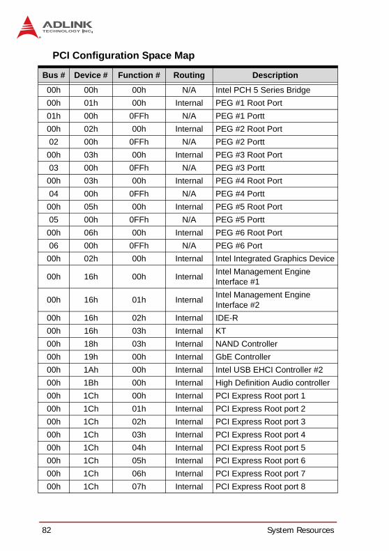
PCI Configuration Space Map
Bus # Device # Function # Routing Description
00h 00h 00h N/A Intel PCH 5 Series Bridge00h 01h 00h Internal PEG #1 Root Port01h 00h 0FFh N/A PEG #1 Portt00h 02h 00h Internal PEG #2 Root Port02 00h 0FFh N/A PEG #2 Portt
00h 03h 00h Internal PEG #3 Root Port03 00h 0FFh N/A PEG #3 Portt
00h 03h 00h Internal PEG #4 Root Port04 00h 0FFh N/A PEG #4 Portt
00h 05h 00h Internal PEG #5 Root Port05 00h 0FFh N/A PEG #5 Portt
00h 06h 00h Internal PEG #6 Root Port06 00h 0FFh N/A PEG #6 Port
00h 02h 00h Internal Intel Integrated Graphics Device
00h 16h 00h Internal Intel Management Engine Interface #1
00h 16h 01h Internal Intel Management Engine Interface #2
00h 16h 02h Internal IDE-R00h 16h 03h Internal KT00h 18h 03h Internal NAND Controller00h 19h 00h Internal GbE Controller 00h 1Ah 00h Internal Intel USB EHCI Controller #200h 1Bh 00h Internal High Definition Audio controller00h 1Ch 00h Internal PCI Express Root port 100h 1Ch 01h Internal PCI Express Root port 200h 1Ch 02h Internal PCI Express Root port 300h 1Ch 03h Internal PCI Express Root port 400h 1Ch 04h Internal PCI Express Root port 500h 1Ch 05h Internal PCI Express Root port 600h 1Ch 06h Internal PCI Express Root port 700h 1Ch 07h Internal PCI Express Root port 8

System Resources 83
NuPRO-A331
Table B-6: PCI Configuration Space Map
Note:(1) SATA controller 2 (D31:F5) is only visible in PCH desktop componentsand when D31:F2 CC.SCC=01h.
00h 1Dh 00h Internal Intel USB EHCI Controller #100h 1Eh 00h N/A Intel PCI to PCI Bridge00h 1Fh 00h N/A Intel LPC Interface Bridge00h 1Fh 02h Internal Intel SATA controller #100h 1Fh 03h Internal Intel SMBus Controller00h 1Fh 05h Internal Intel SATA controller #200h 1Fh 06h Internal Thermal Controller1Eh 0Fh 00h Internal PCI Slot 11Eh 0Eh 00h Internal PCI Slot 21Eh 0Dh 00h Internal PCI Slot 31E0h 0Ch 00h Internal PCI Slot 41E0h 0Bh 00h Internal PCI Slot 51E0h 0Ah 00h Internal PCI Slot 61E0h 09h 00h Internal PCI Slot 720h 00h 0FFh Internal PCIE Port #021h 00h 0FFh Internal PCIE Port #122h 00h 0FFh Internal PCIE Port #223h 00h 0FFh Internal PCIE Port #324h 00h 0FFh Internal PCIE Port #425h 00h 0FFh Internal PCIE Port #526h 00h 0FFh Internal PCIE Port #627h 00h 0FFh Internal PCIE Port #7
Bus # Device # Function # Routing Description

84 System Resources
PCI Interrupt Routing Map
Table B-7: PCI Interrupt Routing Map
PIRQ A B C D E F G H
INT Line INTA INTB INTC INTD PEG Root Port 1-6 INTA INTB INTC INTD
VGA X SATA Controller X X
SATA Controller1 X SMBUS controller X Thermal Controller X
EHCI 1 XEHCI 2 X HDA X
Intel GbE X HECI Host 1 X HECI Host 2 X
IDER Controller X KT Controller X
NAND Controller X PCIE Port 0 INTA INTB INTC INTD PCIE Port 1 INTB INTC INTD INTA PCIE Port 2 INTC INTD INTA INTB PCIE Port 3 INTD INTA INTB INTC PCIE Port 4 INTA INTB INTC INTD PCIE Port 5 INTB INTC INTD INTA PCIE Port 6 INTA INTB INTC INTD PCIE Port 7 INTB INTC INTD INTA
PCI Slot 0 X PCI Slot 1 X PCI Slot 2 XPCI Slot 3 X

Important Safety Instructions 85
NuPRO-A331
Important Safety Instructions
For user safety, please read and follow all instructions,WARNINGS, CAUTIONS, and NOTES marked in this manualand on the associated equipment before handling/operating theequipment.
Read these safety instructions carefully.Keep this user’s manual for future reference.Read the specifications section of this manual for detailed information on the operating environment of this equipment.When installing/mounting or uninstalling/removing equipment:
Turn off power and unplug any power cords/cables.To avoid electrical shock and/or damage to equipment:
Keep equipment away from water or liquid sources;Keep equipment away from high heat or high humidity;Keep equipment properly ventilated (do not block or cover ventilation openings);Make sure to use recommended voltage and power source settings;Always install and operate equipment near an easily accessible electrical socket-outlet;Secure the power cord (do not place any object on/over the power cord);Only install/attach and operate equipment on stable surfaces and/or recommended mountings; and,If the equipment will not be used for long periods of time, turn off and unplug the equipment from its power source.

86 Important Safety Instructions
Never attempt to fix the equipment. Equipment should only be serviced by qualified personnel.
A Lithium-type battery may be provided for uninterrupted, backupor emergency power.
Equipment must be serviced by authorized technicians when:
The power cord or plug is damaged;Liquid has penetrated the equipment;It has been exposed to high humidity/moisture;It is not functioning or does not function according to the user’s manual;It has been dropped and/or damaged; and/or,It has an obvious sign of breakage.
WARNING:
Risk of explosion if battery is replaced with one of an incorrect type. Dispose of used batteries appropriately.

Getting Service 87
NuPRO-A331
Getting Service
Contact us should you require any service or assistance.
ADLINK Technology, Inc. Address: 9F, No.166 Jian Yi Road, Zhonghe District New Taipei City 235, Taiwan
166 9Tel: +886-2-8226-5877 Fax: +886-2-8226-5717 Email: [email protected]
Ampro ADLINK Technology, Inc. Address: 5215 Hellyer Avenue, #110, San Jose, CA 95138, USA Tel: +1-408-360-0200 Toll Free: +1-800-966-5200 (USA only) Fax: +1-408-360-0222 Email: [email protected]
ADLINK Technology (China) Co., Ltd. Address: 300 (201203) 300 Fang Chun Rd., Zhangjiang Hi-Tech Park,
Pudong New Area, Shanghai, 201203 China Tel: +86-21-5132-8988 Fax: +86-21-5132-3588 Email: [email protected]
ADLINK Technology Beijing Address: 1 E 801 (100085)
Rm. 801, Power Creative E, No. 1, B/D Shang Di East Rd., Beijing, 100085 China
Tel: +86-10-5885-8666 Fax: +86-10-5885-8625 Email: [email protected]
ADLINK Technology Shenzhen Address:
A1 2 C (518057) 2F, C Block, Bldg. A1, Cyber-Tech Zone, Gao Xin Ave. Sec. 7, High-Tech Industrial Park S., Shenzhen, 518054 China
Tel: +86-755-2643-4858 Fax: +86-755-2664-6353 Email: [email protected]

88 Getting Service
ADLINK Technology (Europe) GmbH Address: Nord Carree 3, 40477 Duesseldorf, Germany Tel: +49-211-495-5552 Fax: +49-211-495-5557 Email: [email protected]
ADLINK Technology, Inc. (French Liaison Office) Address: 15 rue Emile Baudot, 91300 Massy CEDEX, France Tel: +33 (0) 1 60 12 35 66 Fax: +33 (0) 1 60 12 35 66 Email: [email protected]
ADLINK Technology Japan Corporation Address: 101-0045 3-7-4
374 4FKANDA374 Bldg. 4F, 3-7-4 Kanda Kajicho, Chiyoda-ku, Tokyo 101-0045, Japan
Tel: +81-3-4455-3722 Fax: +81-3-5209-6013 Email: [email protected]
ADLINK Technology, Inc. (Korean Liaison Office) Address: 1506-25 B/D 2
2F, Hando B/D, 1506-25, Seocho-Dong, Seocho-Gu, Seoul 137-070, Korea
Tel: +82-2-2057-0565 Fax: +82-2-2057-0563 Email: [email protected]
ADLINK Technology Singapore Pte. Ltd. Address: 84 Genting Lane #07-02A, Cityneon Design Centre,
Singapore 349584 Tel: +65-6844-2261 Fax: +65-6844-2263 Email: [email protected]
ADLINK Technology Singapore Pte. Ltd. (Indian Liaison Office) Address: No. 1357, "Anupama", Sri Aurobindo Marg, 9th Cross, JP Nagar Phase I, Bangalore - 560078, India Tel: +91-80-65605817 Fax: +91-80-22443548 Email: [email protected]


![Writing a Lexer - CS Home · CS F331 Programming Languages CSCE A331 Programming Language Concepts ... Notes —Lookahead[2/2] Our lexerused the lookaheadstrategy. This …](https://static.fdocuments.in/doc/165x107/5b49b9d77f8b9a5c278b9727/writing-a-lexer-cs-home-cs-f331-programming-languages-csce-a331-programming.jpg)
