NUMERICALCALCULATIONSOFADHESIVEJOINTS...
14
JOURNAL OF THEORETICAL AND APPLIED MECHANICS 45, 2, pp. 311-324, Warsaw 2007 NUMERICAL CALCULATIONS OF ADHESIVE JOINTS SUBJECTED TO SHEARING Jan Godzimirski Sławomir Tkaczuk Military University of Technology, Warsaw e-mail: [email protected]; [email protected] The paper proposes a method for determination of mechanical properties of adhesive layers (necessary for numerical calculations) by means of samples from a glue cast subjected to compression as well as a method of taking adhesion into account in numerical calculations of adhesive bonds. Additionally, a method of numerical modelling of adhesive bonds subjected to shearing was proposed. It was proved that, due to the actual shape of the adhesive layer edge, it can be modelled by one layer of finite elements in numerical calculations. Key words: adhesive bonds, shearing, numerical calculations 1. Introduction The structural gluing is one of the methods of fast integration of parts of machines, installations, vehicles and aircrafts. A properly designed glued joint should be subjected mainly to shearing. So far, there are no credible me- thods of calculating the strength of glued joints. This lack applies even to the static strength of joints subjected to shearing (Godzimirski, 1998). The reason for this is the complex state of stresses in adhesive layers of most glued joints (Godzimirski, 2002), non-linear σ = σ(ε) relation of adhesives (Biedunkiewicz and Majda, 2004) and the possibility of both: cohesive and adhesive wear of an adhesive layer. Cohesion is a state in which particles of a single substance are held together by primary or secondary valence forces observed in the tendency of the substance to stick to itself. Adhesion is a power of an adhesive layer to hold the parts of an assembly together. Two surfaces are held together by interfacial forces which may consist of valence forces or interlocking action. A reliable prediction of the static strength of
-
Upload
duongkhanh -
Category
Documents
-
view
220 -
download
2
Transcript of NUMERICALCALCULATIONSOFADHESIVEJOINTS...
JOURNAL OF THEORETICAL
AND APPLIED MECHANICS
45, 2, pp. 311-324, Warsaw 2007
NUMERICAL CALCULATIONS OF ADHESIVE JOINTSSUBJECTED TO SHEARING
Jan GodzimirskiSławomir Tkaczuk
Military University of Technology, Warsaw
e-mail: [email protected]; [email protected]
The paper proposes a method for determination of mechanical propertiesof adhesive layers (necessary for numerical calculations) by means ofsamples from a glue cast subjected to compression as well as a methodof taking adhesion into account in numerical calculations of adhesivebonds. Additionally, a method of numerical modelling of adhesive bondssubjected to shearing was proposed. It was proved that, due to the actualshape of the adhesive layer edge, it can be modelled by one layer of finiteelements in numerical calculations.
Key words: adhesive bonds, shearing, numerical calculations
1. Introduction
The structural gluing is one of the methods of fast integration of parts ofmachines, installations, vehicles and aircrafts. A properly designed glued jointshould be subjected mainly to shearing. So far, there are no credible me-thods of calculating the strength of glued joints. This lack applies even tothe static strength of joints subjected to shearing (Godzimirski, 1998). Thereason for this is the complex state of stresses in adhesive layers of mostglued joints (Godzimirski, 2002), non-linear σ = σ(ε) relation of adhesives(Biedunkiewicz and Majda, 2004) and the possibility of both: cohesive andadhesive wear of an adhesive layer. Cohesion is a state in which particles ofa single substance are held together by primary or secondary valence forcesobserved in the tendency of the substance to stick to itself. Adhesion is apower of an adhesive layer to hold the parts of an assembly together. Twosurfaces are held together by interfacial forces which may consist of valenceforces or interlocking action. A reliable prediction of the static strength of
312 J. Godzimirski, S. Tkaczuk
glued joints is not possible without numerical calculations (Godzimirski andTkaczuk, 1998; Gutkowski et al., 1996). However, the application of nume-rical methods requires knowledge of mechanical properties of the materialswhich constitute the joint under examination. Among others, one has to ta-ke into account the σ = σ(ε) relation of the adhesive with the full range ofits possible strains as well as adopt a correct numerical model of the gluedjoint.Determination of the σ = σ(ε) relation of an adhesive rises controversy
relating to the possibility of determining such adhesive layer properties usingcast samples or samples cut out of a cured block of the adhesive. Dimensionsof adhesive layers (thickness ∼ 0.1mm) cause problems in the attempts to de-termine even the initial parts (ELEMENTS) of their σ = σ(ε) characteristics.Described trials to experimentally determine Young’s modulus of adhesivelayers (Czarnomska, 1987; Świtkiewicz, 1978) seem to carry implausible errorsbecause of the research methods used. Moreover, established values lack posi-tive verification by strength calculations. The authors’ own tests (Godzimirski,1982) as well as those presented in Biedunkiewicz and Majda (2004) prove thatmechanical properties of adhesive layers determined by the σ = σ(ε) relationare comparable to those made from cured adhesive samples, thus making it po-ssible to determine mechanical properties of adhesive layers using samples fromthe adhesive cast. The experimental determination of the σ = σ(ε) characteri-stic curve by means of such samples presents no technical problem. A prepara-tion of oar shaped samples is relatively simple. Also the measurements of theirstrains are more accurate than the measurements of adhesive layers strains.However, tension curves of the oar shaped samples usually do not allow one todetermine the full range of the σ = σ(ε) characteristic of the adhesive layer.Neither do they allow one to determine the value of breaking stresses whichin adhesive layers are usually greater than static strength of cast samples. Forexample, the breaking stresses of Epidian 57 adhesive layer reach values inthe range of 75MPa (Godzimirski and Tkaczuk, 2002). Additionally, samplesmade from adhesive allow one to determine only cohesion properties of theadhesive.Therefore the problem of numerical calculation of adhesive bonds re-
quires:
• to work out a method for determination of mechanic properties of adhe-sive layers in the full range of their strains,
• to use a correct numerical model of the joint,
• to take into account in numerical calculations the adhesion properties ofthe adhesive layer.
In this paper, the solution for the above mentioned problems are presented.
Numerical calculations of adhesive joints... 313
2. Determination of mechanical properties of the adhesive
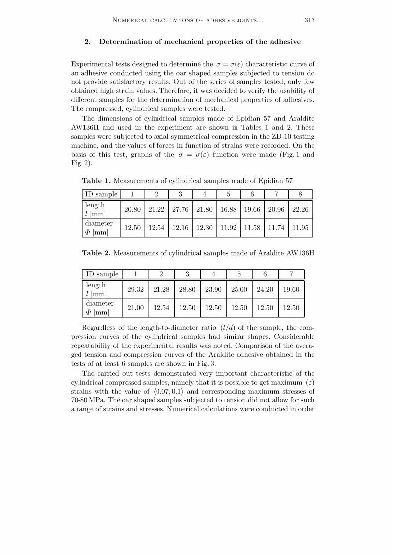
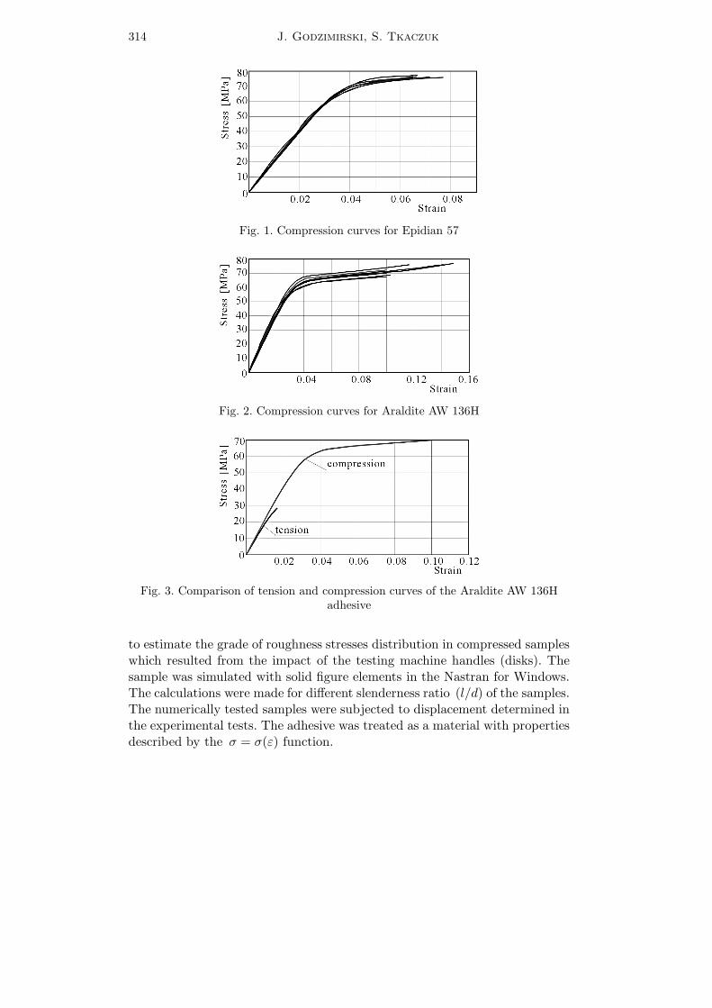
Experimental tests designed to determine the σ = σ(ε) characteristic curve ofan adhesive conducted using the oar shaped samples subjected to tension donot provide satisfactory results. Out of the series of samples tested, only fewobtained high strain values. Therefore, it was decided to verify the usability ofdifferent samples for the determination of mechanical properties of adhesives.The compressed, cylindrical samples were tested.The dimensions of cylindrical samples made of Epidian 57 and Araldite
AW136H and used in the experiment are shown in Tables 1 and 2. Thesesamples were subjected to axial-symmetrical compression in the ZD-10 testingmachine, and the values of forces in function of strains were recorded. On thebasis of this test, graphs of the σ = σ(ε) function were made (Fig. 1 andFig. 2).
Table 1. Measurements of cylindrical samples made of Epidian 57
ID sample 1 2 3 4 5 6 7 8
length20.80 21.22 27.76 21.80 16.88 19.66 20.96 22.26
l [mm]diameter
12.50 12.54 12.16 12.30 11.92 11.58 11.74 11.95Φ [mm]
Table 2. Measurements of cylindrical samples made of Araldite AW136H
ID sample 1 2 3 4 5 6 7
length29.32 21.28 28.80 23.90 25.00 24.20 19.60
l [mm]diameter
21.00 12.54 12.50 12.50 12.50 12.50 12.50Φ [mm]
Regardless of the length-to-diameter ratio (l/d) of the sample, the com-pression curves of the cylindrical samples had similar shapes. Considerablerepeatability of the experimental results was noted. Comparison of the avera-ged tension and compression curves of the Araldite adhesive obtained in thetests of at least 6 samples are shown in Fig. 3.The carried out tests demonstrated very important characteristic of the
cylindrical compressed samples, namely that it is possible to get maximum (ε)strains with the value of 〈0.07, 0.1〉 and corresponding maximum stresses of70-80MPa. The oar shaped samples subjected to tension did not allow for sucha range of strains and stresses. Numerical calculations were conducted in order
314 J. Godzimirski, S. Tkaczuk
Fig. 1. Compression curves for Epidian 57
Fig. 2. Compression curves for Araldite AW 136H
Fig. 3. Comparison of tension and compression curves of the Araldite AW 136Hadhesive
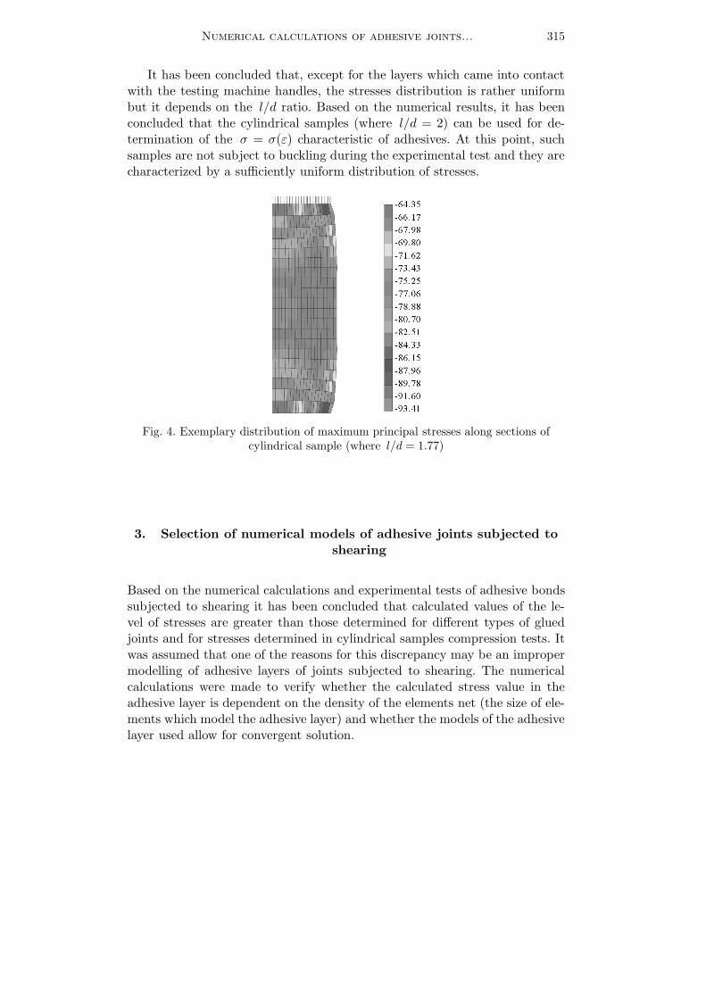
to estimate the grade of roughness stresses distribution in compressed sampleswhich resulted from the impact of the testing machine handles (disks). Thesample was simulated with solid figure elements in the Nastran for Windows.The calculations were made for different slenderness ratio (l/d) of the samples.The numerically tested samples were subjected to displacement determined inthe experimental tests. The adhesive was treated as a material with propertiesdescribed by the σ = σ(ε) function.
Numerical calculations of adhesive joints... 315
It has been concluded that, except for the layers which came into contactwith the testing machine handles, the stresses distribution is rather uniformbut it depends on the l/d ratio. Based on the numerical results, it has beenconcluded that the cylindrical samples (where l/d = 2) can be used for de-termination of the σ = σ(ε) characteristic of adhesives. At this point, suchsamples are not subject to buckling during the experimental test and they arecharacterized by a sufficiently uniform distribution of stresses.
Fig. 4. Exemplary distribution of maximum principal stresses along sections ofcylindrical sample (where l/d = 1.77)
3. Selection of numerical models of adhesive joints subjected toshearing
Based on the numerical calculations and experimental tests of adhesive bondssubjected to shearing it has been concluded that calculated values of the le-vel of stresses are greater than those determined for different types of gluedjoints and for stresses determined in cylindrical samples compression tests. Itwas assumed that one of the reasons for this discrepancy may be an impropermodelling of adhesive layers of joints subjected to shearing. The numericalcalculations were made to verify whether the calculated stress value in theadhesive layer is dependent on the density of the elements net (the size of ele-ments which model the adhesive layer) and whether the models of the adhesivelayer used allow for convergent solution.
316 J. Godzimirski, S. Tkaczuk
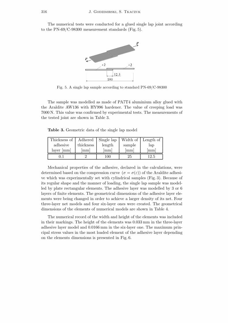
The numerical tests were conducted for a glued single lap joint accordingto the PN-69/C-98300 measurement standards (Fig. 5).
Fig. 5. A single lap sample according to standard PN-69/C-98300
The sample was modelled as made of PA7T4 aluminium alloy glued withthe Araldite AW136 with HY996 hardener. The value of creeping load was7000N. This value was confirmed by experimental tests. The measurements ofthe tested joint are shown in Table 3.
Table 3. Geometric data of the single lap model
Thickness of Adhered Single lap Width of Length ofadhesive thickness length sample laplayer [mm] [mm] [mm] [mm] [mm]
0.1 2 100 25 12.5
Mechanical properties of the adhesive, declared in the calculations, weredetermined based on the compression curve (σ = σ(ε)) of the Araldite adhesi-ve which was experimentally set with cylindrical samples (Fig. 3). Because ofits regular shape and the manner of loading, the single lap sample was model-led by plate rectangular elements. The adhesive layer was modelled by 3 or 6layers of finite elements. The geometrical dimensions of the adhesive layer ele-ments were being changed in order to achieve a larger density of its net. Fourthree-layer net models and four six-layer ones were created. The geometricaldimensions of the elements of numerical models are shown in Table 4.
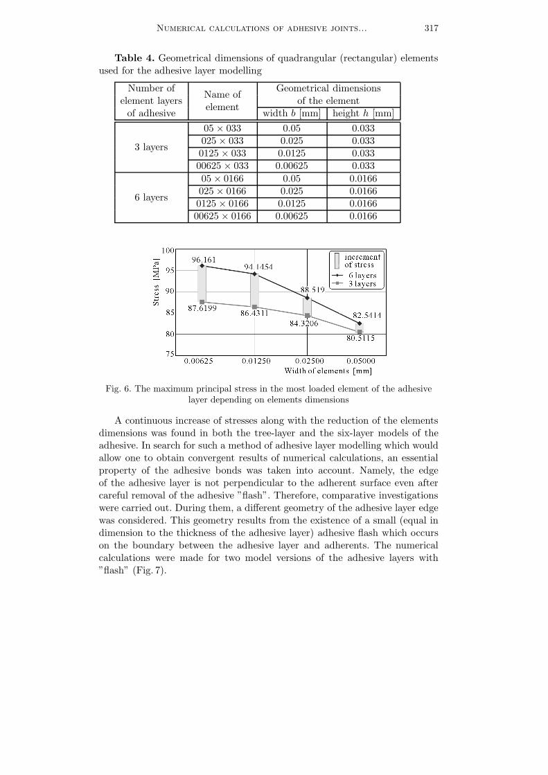
The numerical record of the width and height of the elements was includedin their markings. The height of the elements was 0.033mm in the three-layeradhesive layer model and 0.0166mm in the six-layer one. The maximum prin-cipal stress values in the most loaded element of the adhesive layer dependingon the elements dimensions is presented in Fig. 6.
Numerical calculations of adhesive joints... 317
Table 4. Geometrical dimensions of quadrangular (rectangular) elementsused for the adhesive layer modelling
Number ofName ofelement
Geometrical dimensionselement layers of the elementof adhesive width b [mm] height h [mm]
3 layers
05 × 033 0.05 0.033025× 033 0.025 0.0330125 × 033 0.0125 0.03300625 × 033 0.00625 0.033
6 layers
05× 0166 0.05 0.0166025 × 0166 0.025 0.01660125 × 0166 0.0125 0.016600625 × 0166 0.00625 0.0166
Fig. 6. The maximum principal stress in the most loaded element of the adhesivelayer depending on elements dimensions
A continuous increase of stresses along with the reduction of the elementsdimensions was found in both the tree-layer and the six-layer models of theadhesive. In search for such a method of adhesive layer modelling which wouldallow one to obtain convergent results of numerical calculations, an essentialproperty of the adhesive bonds was taken into account. Namely, the edgeof the adhesive layer is not perpendicular to the adherent surface even aftercareful removal of the adhesive ”flash”. Therefore, comparative investigationswere carried out. During them, a different geometry of the adhesive layer edgewas considered. This geometry results from the existence of a small (equal indimension to the thickness of the adhesive layer) adhesive flash which occurson the boundary between the adhesive layer and adherents. The numericalcalculations were made for two model versions of the adhesive layers with”flash” (Fig. 7).
318 J. Godzimirski, S. Tkaczuk
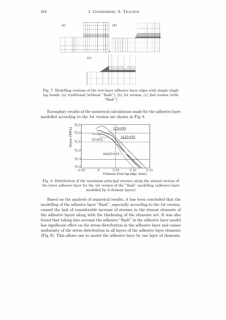
Fig. 7. Modelling versions of the tree-layer adhesive layer edges with simple singlelap bonds: (a) traditional (without ”flash”), (b) 1st version, (c) 2nd version (with
”flash”)
Exemplary results of the numerical calculations made for the adhesive layermodelled according to the 1st version are shown in Fig. 8.
Fig. 8. Distribution of the maximum principal stresses along the utmost section ofthe lower adhesive layer for the 1st version of the ”flash” modelling (adhesive layer
modelled by 3 element layers)
Based on the analysis of numerical results, it has been concluded that themodelling of the adhesive layer ”flash”, especially according to the 1st version,caused the lack of considerable increase of stresses in the utmost elements ofthe adhesive layers along with the thickening of the elements net. It was alsofound that taking into account the adhesive ”flash” in the adhesive layer modelhas significant effect on the stress distribution in the adhesive layer and causesuniformity of the stress distribution in all layers of the adhesive layer elements(Fig. 9). This allows one to model the adhesive layer by one layer of elements.
Numerical calculations of adhesive joints... 319
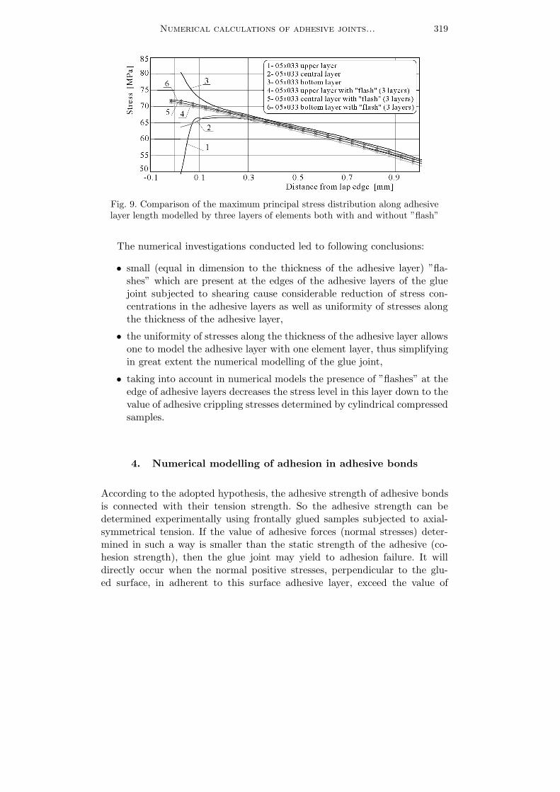
Fig. 9. Comparison of the maximum principal stress distribution along adhesivelayer length modelled by three layers of elements both with and without ”flash”
The numerical investigations conducted led to following conclusions:
• small (equal in dimension to the thickness of the adhesive layer) ”fla-shes” which are present at the edges of the adhesive layers of the gluejoint subjected to shearing cause considerable reduction of stress con-centrations in the adhesive layers as well as uniformity of stresses alongthe thickness of the adhesive layer,
• the uniformity of stresses along the thickness of the adhesive layer allowsone to model the adhesive layer with one element layer, thus simplifyingin great extent the numerical modelling of the glue joint,
• taking into account in numerical models the presence of ”flashes” at theedge of adhesive layers decreases the stress level in this layer down to thevalue of adhesive crippling stresses determined by cylindrical compressedsamples.
4. Numerical modelling of adhesion in adhesive bonds
According to the adopted hypothesis, the adhesive strength of adhesive bondsis connected with their tension strength. So the adhesive strength can bedetermined experimentally using frontally glued samples subjected to axial-symmetrical tension. If the value of adhesive forces (normal stresses) deter-mined in such a way is smaller than the static strength of the adhesive (co-hesion strength), then the glue joint may yield to adhesion failure. It willdirectly occur when the normal positive stresses, perpendicular to the glu-ed surface, in adherent to this surface adhesive layer, exceed the value of
320 J. Godzimirski, S. Tkaczuk
experimentally determined adhesion stresses. Therefore, in numerical calcu-lations, it is necessary to check not only the effort of the adhesive layeraccording to a specific effort hypothesis for determination of adhesive co-hesion effort (hypothesis of the maximal stress seems to be right for theassessment of adhesive layer effort (Godzimirski, 1985; Kubissa, 1982)) butthe value of normal positive stresses perpendicular to the glued surface aswell.
It was decided to verify the adopted hypothesis by conducting an experi-mental test and numerical calculations.
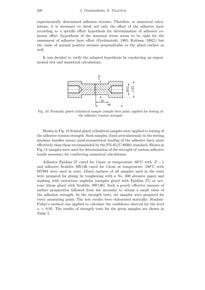
Fig. 10. Frontally glued cylindrical sample (simple butt joint) applied for testing ofthe adhesive tension strength
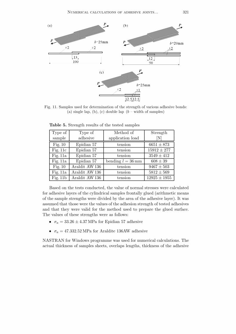
Shown in Fig. 10 frontal glued cylindrical samples were applied to testing ofthe adhesive tension strength. Such samples, fixed articulationaly in the testingmachine handles ensure axial-symmetrical loading of the adhesive layer moreeffectively than those recommended by the PN-65/C-89301 standard. Shown inFig. 11 samples were used for determination of the strength of various adhesivebonds necessary for conducting numerical calculations.
Adhesive Epidian 57 cured for 1 hour at temperature 60◦C with Z − 1and adhesive Araldite AW136 cured for 1 hour at temperature 100◦C withHY994 were used in tests. Glued surfaces of all samples used in the testswere prepared for gluing by roughening with a No. 300 abrasive paper andwashing with extraction naphtha (samples glued with Epidian 57) or ace-tone (those glued with Araldite AW136). Such a poorly effective manner ofsurface preparation followed from the necessity to obtain a small value ofthe adhesion strength. In the strength tests, six samples were prepared forevery measuring point. The test results were elaborated statically: Student-Fisher’s method was applied to calculate the confidence interval for the levelα = 0.95. The results of strength tests for the given samples are shown inTable 5.
Numerical calculations of adhesive joints... 321
Fig. 11. Samples used for determination of the strength of various adhesive bonds:(a) single lap, (b), (c) double lap (b – width of samples)
Table 5. Strength results of the tested samples
Type of Type of Method of Strengthsample adhesive application load [N]
Fig. 10 Epidian 57 tension 6651 ± 873Fig. 11c Epidian 57 tension 15912 ± 277Fig. 11a Epidian 57 tension 3549 ± 412Fig. 11a Epidian 57 bending l = 36mm 608± 39Fig. 10 Araldit AW136 tension 9467 ± 503Fig. 11a Araldit AW136 tension 5812 ± 569Fig. 11b Araldit AW136 tension 12925 ± 1955
Based on the tests conducted, the value of normal stresses were calculatedfor adhesive layers of the cylindrical samples frontally glued (arithmetic meansof the sample strengths were divided by the area of the adhesive layer). It wasassumed that those were the values of the adhesion strength of tested adhesivesand that they were valid for the method used to prepare the glued surface.The values of these strengths were as follows:
• σa = 33.26 ± 4.37MPa for Epidian 57 adhesive
• σa = 47.332.52MPa for Araldite 136AW adhesive
NASTRAN for Windows programme was used for numerical calculations. Theactual thickness of samples sheets, overlaps lengths, thickness of the adhesive
322 J. Godzimirski, S. Tkaczuk
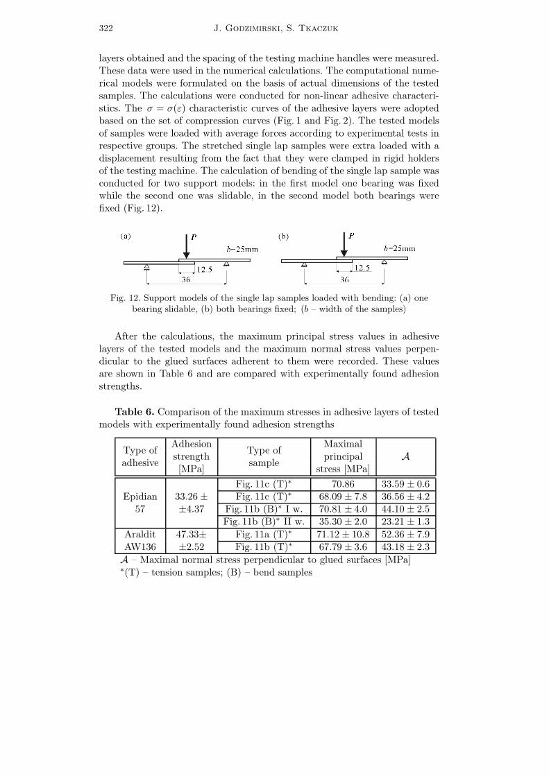
layers obtained and the spacing of the testing machine handles were measured.These data were used in the numerical calculations. The computational nume-rical models were formulated on the basis of actual dimensions of the testedsamples. The calculations were conducted for non-linear adhesive characteri-stics. The σ = σ(ε) characteristic curves of the adhesive layers were adoptedbased on the set of compression curves (Fig. 1 and Fig. 2). The tested modelsof samples were loaded with average forces according to experimental tests inrespective groups. The stretched single lap samples were extra loaded with adisplacement resulting from the fact that they were clamped in rigid holdersof the testing machine. The calculation of bending of the single lap sample wasconducted for two support models: in the first model one bearing was fixedwhile the second one was slidable, in the second model both bearings werefixed (Fig. 12).
Fig. 12. Support models of the single lap samples loaded with bending: (a) onebearing slidable, (b) both bearings fixed; (b – width of the samples)
After the calculations, the maximum principal stress values in adhesivelayers of the tested models and the maximum normal stress values perpen-dicular to the glued surfaces adherent to them were recorded. These valuesare shown in Table 6 and are compared with experimentally found adhesionstrengths.
Table 6. Comparison of the maximum stresses in adhesive layers of testedmodels with experimentally found adhesion strengths
Type ofadhesive
AdhesionType ofsample
Maximalstrength principal A[MPa] stress [MPa]
Epidian57
33.26 ±±4.37
Fig. 11c (T)∗ 70.86 33.59 ± 0.6Fig. 11c (T)∗ 68.09 ± 7.8 36.56 ± 4.2Fig. 11b (B)∗ I w. 70.81 ± 4.0 44.10 ± 2.5Fig. 11b (B)∗ II w. 35.30 ± 2.0 23.21 ± 1.3
Araldit 47.33± Fig. 11a (T)∗ 71.12 ± 10.8 52.36 ± 7.9AW136 ±2.52 Fig. 11b (T)∗ 67.79 ± 3.6 43.18 ± 2.3A – Maximal normal stress perpendicular to glued surfaces [MPa]∗(T) – tension samples; (B) – bend samples
Numerical calculations of adhesive joints... 323
Considering the confidence intervals of the experimentally obtained results,it can be concluded that numerically calculated, maximum normal stressesperpendicular to the glued surfaces, did not exceed in the overlap stretchedsamples the adhesion strength values, which were assumed to be equal tothe tension strength of frontal adhesive layers. Calculated for the overlappedsamples under bending, these stresses differed considerably from the assumedadhesion strengths. This resulted from the fact that – because of the supportmethod – none of the computational models properly map the actual strengthtest conditions. The actual conditions of the experiment were intermediatebetween those adopted in calculations. Therefore, the calculated stress valuewas too big for the first version of calculation and too small for the secondone. Therefore, single lap samples under bending can be subject to comparisontests, but not used for determination of the value of breaking stress of theadhesive layer. It seems that the proposed method of taking into accountthe adhesive layer adhesion properties may be used in numerical strengthcalculations of adhesive bonds.
5. Summary
Due to the complex state of stresses in adhesive layers, the Finite ElementMethod (FEM) is useful for calculations of the adhesive bonds strength.The level of stresses and strains in thin adhesive layers are comparable
with the level of stresses and strains obtained in compressed samples whichhave greater dimensions and volume.It seems that the proposed method of determining mechanical properties
of adhesives and the proposition of taking into account the adhesion forcesmay be useful in numerical calculations of adhesive bonds and should enableprediction of the adhesive joints strength by (FEM).The use of the Finite Element Method does not always allow one to pre-
cisely model the actual load conditions of calculated elements or joints. Nu-merically analysed adhesive bonds are very ”sensitive” to accuracy of theirmapping by means of a computational model.
References
1. Biedunkiewicz W., Majda P., 2004, A model of an adhesive joint subjectedto shearing, Postępy Technologii Maszyn, 28, 1, 23-36
324 J. Godzimirski, S. Tkaczuk
2. Czarnomska M., 1987, Wpływ starzenia na nośność metalowych połączeńklejonych, Rozprawa doktorska, Politechnika Warszawska
3. Godzimirski J., 1982, Ocena przydatności znormalizowanych prób do okre-ślania właściwości wytrzymałościowych klejów do metali, Rozprawa doktorska,WAT
4. Godzimirski J., 1985, Określanie naprężeń w spoinach klejowych metodą ele-mentów skończonych, Biuletyn WAT, 399, 11, 77–81
5. Godzimirski J., 1998, Prognozowanie wytrzymałości doraźnej połączeń klejo-wych, Postępy Technologii Maszyn i Urządzeń, 22, 3, 5-24
6. Godzimirski J., 2002,Wytrzymałość doraźna konstrukcyjnych połączeń klejo-wych, WNT, Warszawa
7. Godzimirski J., Tkaczuk S., 1998, Ocena przydatności metod numerycznychdo obliczania wytrzymałości doraźnej połączeń klejowych, Biuletyn WAT, 553,9, 111-120
8. Godzimirski J., Tkaczuk S., 2002, Wyznaczanie modułu Younga klejówkonstrukcyjnych, Biuletyn WAT, 600, 8, 159-166
9. Gutkowski R.M., Conrad J., Pelikane P.J., 1996, Formulation of a bon-dline element of modeling glued joints in wood, Mechanika Teoretyczna i Sto-sowana, 34, 1, 101-128
10. Kubissa J., 1982, Problemy wyznaczania nośności klejonych połączeń metali,Inżynieria i Budownictwo, 453/454, 8/9, 169-171
11. Świtkiewicz R., 1978, Klejenie w konstrukcjach lotniczych, Technika Lotniczai Astronautyczna, 11, 11-14
Numeryczne obliczanie połączeń klejowych obciążonych na ścinanie
Streszczenie
W pracy zaproponowano metodę wyznaczania właściwości mechanicznych spo-in klejowych potrzebnych do obliczeń numerycznych za pomocą próbek odlewanychz kleju poddawanych ściskaniu oraz sposób uwzględniania adhezji w obliczeniach nu-merycznych połączeń klejowych. Ponadto zaproponowano sposób modelowania nume-rycznego spoin połączeń obciążonych na ścinanie i wykazano, że ze względu na rze-czywisty kształt ich krawędzi w obliczeniach numerycznych można modelować spoinęjedną warstwą elementów skończonych.
Manuscript received July 18, 2006; accepted for print December 1, 2006