Numerical Simulation of Oil Well Cementing and Gas ...
23
Numerical Simulation of Oil Well Cementing and Gas Migration Process Amir Mofakham, 1 Farid Rousta, 1 Mehrdad Massoudi, 2 Eilis Rosenbaum, 2 Barbara Kutchko 2 and Goodarz Ahmadi 1 1 Department of Mechanical and Aeronautical Engineering Clarkson University, Potsdam, NY & 2 National Energy Technology Laboratory US Department of Energy, Pittsburgh, PA
Transcript of Numerical Simulation of Oil Well Cementing and Gas ...

Numerical Simulation of Oil Well Cementing and Gas Migration Process
Amir Mofakham,1 Farid Rousta,1 Mehrdad Massoudi,2 Eilis Rosenbaum,2
Barbara Kutchko2 and Goodarz Ahmadi1
1 Department of Mechanical and Aeronautical Engineering Clarkson University, Potsdam, NY
&2 National Energy Technology LaboratoryUS Department of Energy, Pittsburgh, PA
Outline
• Introduction• Cementing Process• Gas Migration• Objectives• Results• Conclusions

Introduction

Well Cementing Process
• Inject drilling fluid
• Inject spacer fluid• Compatible with the
drilling fluid/cement slurry• Change surface wettability• Remove debris
• Inject cement slurry
• Inject mud
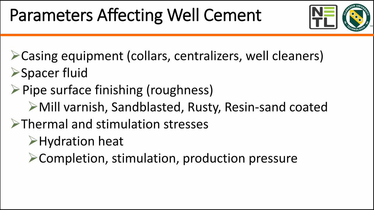
Parameters Affecting Well Cement
Casing equipment (collars, centralizers, well cleaners)Spacer fluidPipe surface finishing (roughness) Mill varnish, Sandblasted, Rusty, Resin-sand coated
Thermal and stimulation stresses Hydration heatCompletion, stimulation, production pressure

Gas Migration
• During the cementing process, cement experiencesthree distinct phases (Slurry, Gel, and Solid).
• In the slurry phase, the cement begins to hydrate,pore pressure begins to drop, and gas migrationcould begin to occur due to the higher formationpressure.
• In the solid phase, the cement becomesimpermeable and no fluid can invade through
• The gel phase is most critical during whichformation gas could migrate into the cement if thepore pressure is lower than the formationpressure.
Beirut and Cheung, SPE Production Engineering, 1990

Industrial Practices to Prevent Gas Migration
• Properly clean the wellbore
• Use proper fluid spacers
• Use additives to
• Control fluid loss
• Control the setting time
• Reduce the transition time
• Immobilize the fluid within the pore spaces
• Etc.
Cheung and Beirut, Journal of Petroleum Technology, 1985

Objectives
Develop a computer model for gas migration in well cement
Simulate gas bubble motion in cement paste
Provide a better understanding of the gas migration process in well cement
Develop a computational model for cement slurry injection
http://www.drillingcourse.com/2015/12/introduction-to-cementing.html

Modeling

Numerical Approach
• Assumed two-phase flows
• The VOF multiphase model of ANSYS-Fluent

Rheological Model
Properties
Liquid Cement Slurry Drilling Fluid (Water)
Density (𝑘𝑔/𝑚3) 1200 998
Surface Tension (N/m) 0.07 0.07
Rheological Model Herschel-Bulkley Model Linear Newtonian
Viscosity (𝑘𝑔/𝑚𝑠) - 1 × 10⁻³
Consistency Index (k) (𝑘𝑔𝑠𝑛−2/𝑚)
0.6 -
Power-Law Index (n) 0.4 -
Yield Shear Stress 𝜏0 (Pa) 1.4 -
Critical Shear Rate ሶ𝛾𝑐 (1/s) 5.5 -
Ӗ𝜏 = ന𝜏0 + 𝜂𝐷
𝜂 =𝜏0
ሶ𝛾+ 𝑘
ሶ𝛾
ሶ𝛾𝑐
𝑛−1if ሶ𝛾 < ሶ𝛾𝑐
𝜂 =𝜏0 2−
ሶ𝛾
ሶ𝛾𝑐
ሶ𝛾𝑐+ 𝑘 2 − 𝑛 + (𝑛 − 1)
ሶ𝛾
ሶ𝛾𝑐if ሶ𝛾 > ሶ𝛾𝑐
Herschel-Bulkley Model

Results

Gas Migration
Geometry
Length (m) 1
Width (cm) 6
Air Inlet Size (mm) 5
Cement Slurry Properties
Viscosity (kg/ms) 1
Density (𝑘𝑔/𝑚3) 998
Surface Tension (N/m) 0.07
V = 0.01 (m/s) V = 1 (m/s)V = 0.2 (m/s)
2D Channel with Flat Walls
Slurry Model: Newtonian

Cylindrical Geometry
14
Air Inlet
Length (m) 1
Inner Diameter (cm) 20
Outer Diameter (cm) 36
Air Inlet Diameter (cm) 1
Number of Elements 770,511
Gas Migration
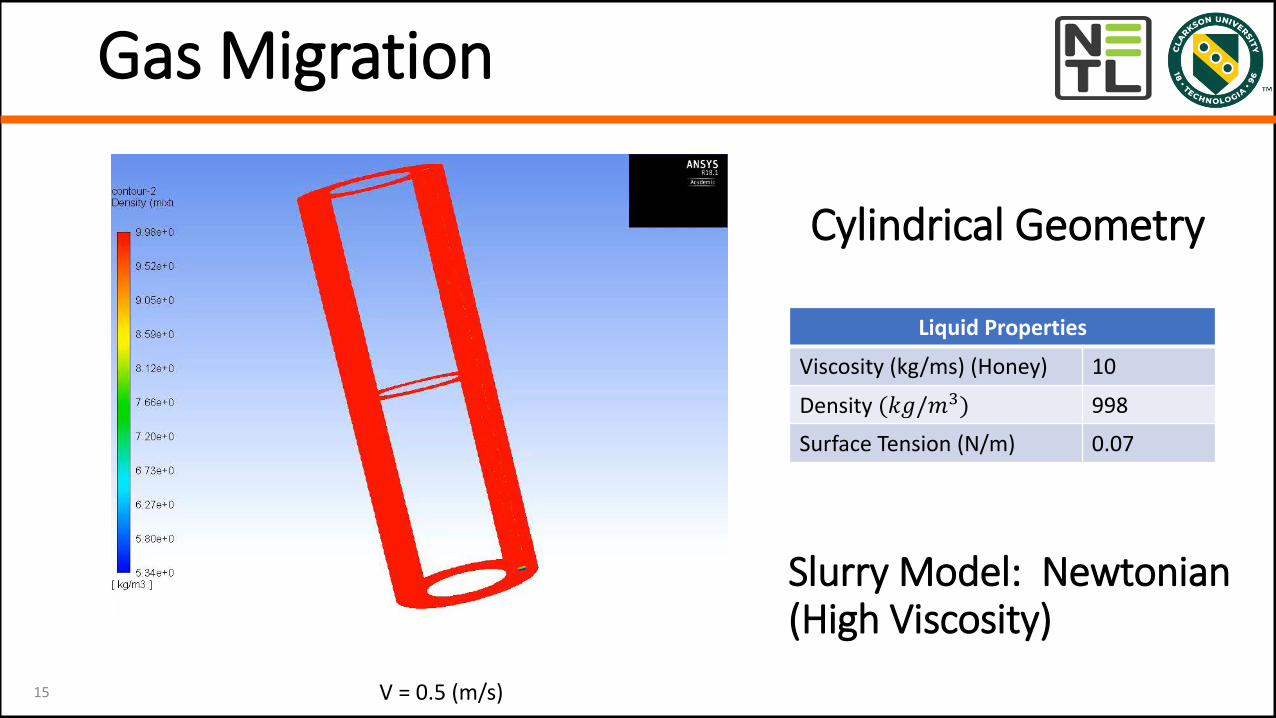
15
Liquid Properties
Viscosity (kg/ms) (Honey) 10
Density (𝑘𝑔/𝑚3) 998
Surface Tension (N/m) 0.07
V = 0.5 (m/s)
Gas Migration
Cylindrical Geometry
Slurry Model: Newtonian (High Viscosity)
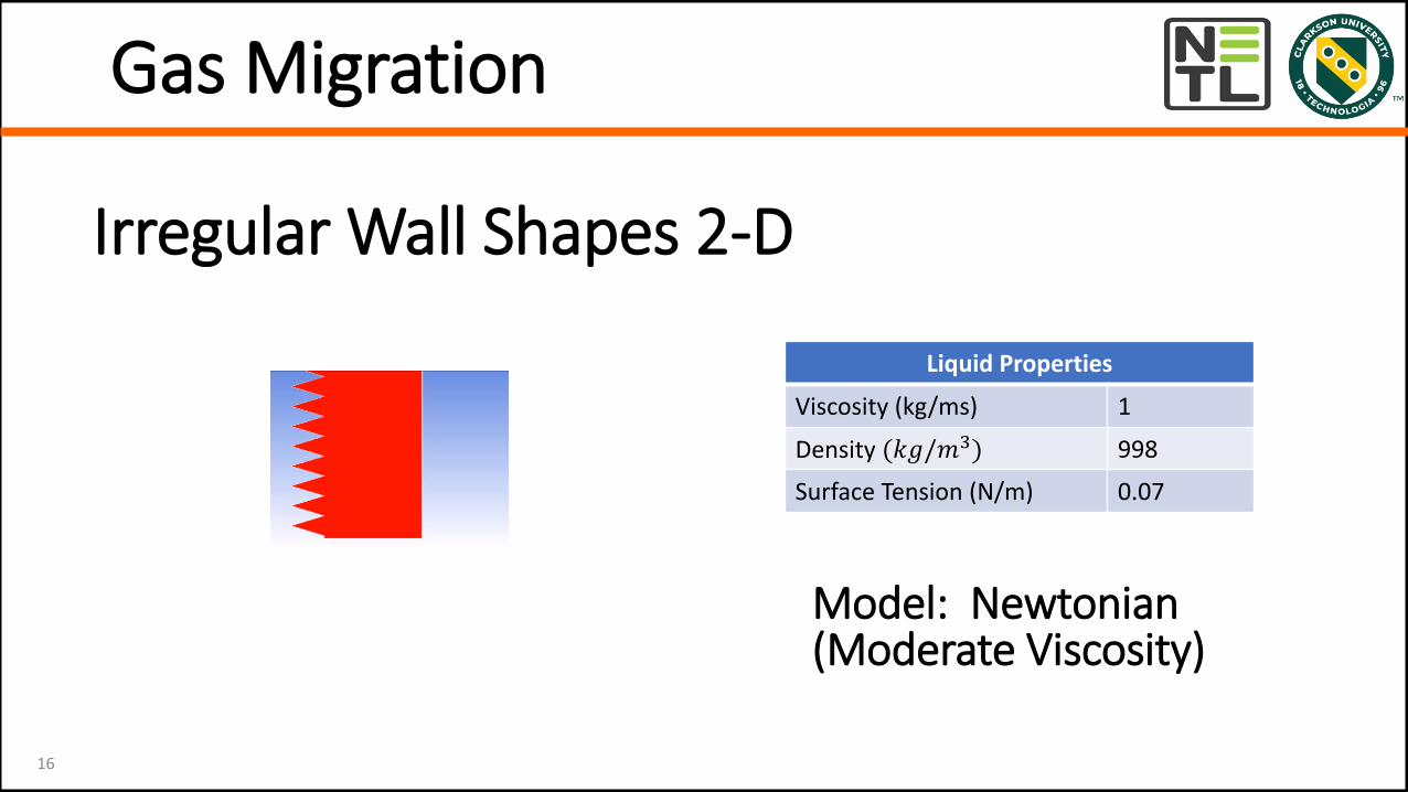
Irregular Wall Shapes 2-D
16
Liquid Properties
Viscosity (kg/ms) 1
Density (𝑘𝑔/𝑚3) 998
Surface Tension (N/m) 0.07
Gas Migration
Model: Newtonian (Moderate Viscosity)

Irregular Wall Shapes 2-D
17
Liquid Properties
Viscosity (kg/ms) 1
Density (𝑘𝑔/𝑚3) 998
Surface Tension (N/m) 0.07
Cement Inlet Velocity (m/s) 0.5
Cement Injection Modeling
ModelsCement: Herschel-BulkleyDrilling Fluid: Newtonian

Sample SimulationsVelocity Contours
V=0.05 (m/s) V=0.1 (m/s) V=0.5 (m/s)
Cement Injection Modeling
Cement: Herschel-BulkleyDrilling Fluid: Newtonian

Cement Patched in the Tube
Cement Injection Modeling
ModelsCement: Herschel-BulkleyDrilling Fluid: Newtonian

3D Flat Walls Well
Inlet Velocity =0.05 m/s Inlet Velocity =0.2 m/s
Cement Injection Modeling
Conclusions
• A VOF model for gas bubble motion in cement wasdeveloped.
• The Newtonian and Herschel-Bulkley models was used forcement slurry.
• Simulations were presented to 2-D flat and rough wall aswell as annulus well cement models.
• CFD could provide insight into the gas migration process.
• Further studies of the gas migration process is needed.

Future Works
• Model cement pastes as non-linear fluids exhibitingviscoelasticity, thixotropy, yield stress, shear-thinningeffects (Tao et al. 2020, 2021)
• Include the reduction of pore pressure using empiricalmodels
• Simulate the fluid migration as the pore pressure reduces
• Develop a rheological model including the pore pressurereduction
• Develop a constitutive law for cement paste solidificationprocess