
Numerical Simulation of Impacts involving a Collapsible ...
6
Abstract—A numerical model for the simulation of dynamic compression of a nonlinear multilayer structure subjected to transient compressive excitation is described and tested. It is shown that impacts induce a chaotic collapse of crumple layers. The simulations predict shock pulses and intralaminar forces. Simulated shock pulses that a free-falling mass is subjected to, and the corresponding animated deformation histories of the layers, are compared with the high-speed videography. Cushioning performance maps and shock response spectrums maps obtained from the simulations are presented. Index Terms— Collapsible multilayer structure, impacts, nonlinear dynamics, numerical simulation. I. INTRODUCTION The paper deals with structures assembled from layers of a collapsible material such as one shaped as honeycomb or corrugations. An example of the typical stress-deflection characteristics of a single layer of corrugated fiberboard is illustrated in Fig. 1. Fig. 1 Compression characteristics of a layer corrugated fiberboard (flute type B) at the strain rate of 0.01s -1 . Nonintrusive investigation of the behavior of multilayer material under transient excitation, such as produced by a free-falling mass, is typically determined indirectly from the measured shock transmitted to the mass. Supplementary insight Manuscript received March 21, 2007. M. A. Sek is with the School of Architectural, Civil and Mechanical Engineering, Victoria University, Melbourne, Australia (phone: +(61-3) 9919-4205; fax: +(61-3) 9919-4139; e-mail: [email protected]). into the phenomenon can be provided by a high-speed videography, particularly when layers start to collapse under excessive stress, however frame rates required are in tens of thousand per second ([1],[2]). Shock response of these structures is rather chaotic and small variations to properties of the layers' components may produce significantly differing response. Such multilayer material, when subjected to significant impacts, may exhibit a collapse of layers and this dissipative effect may be utilized for shock attenuation [3]. For monotonically hardening cushioning materials, with their near half-sine shock pulses, the so called cushion curves are sufficient characteristics for optimization of their behavior [4]. Shocks produced by a collapsing material and their frequency content are more complex. In order to augment experimental techniques and to study optimum configurations of engineered cushion pads, the need for a numerical tool for simulation of impacts involving collapsible nonlinear multilayer material has been identified. II. MODEL DESCRIPTION The model was developed in Matlab® and Simulink® as illustrated in Fig. 2. A single layer was modeled as a discrete uniaxial two-DOF system. A generic SDOF system with vibrating base and/or force excitation was programmed as two coupled ordinary differential equations (ODE) in such a way as to enable the simulation of practically any nonlinearity of the spring and of the damping element. Prevention of the visco-elastic linkage to operate in tension was incorporated in the model in order to simulate, for example, layers losing contact with one another, such as in the post-shock period or during the bouncing induced by vibrations. The complex behavior of collapsing layer was coded in a parametric fashion and accomplished by defining a Simulink® s-function [5]. As illustrated in Fig. 2, two SDOF subsystems were joined to form the model of a single layer, whose bottom spring was used to simulate contact conditions. A SDOF was adapted to model the platen of a free-fall cushion testing apparatus or, alternatively, the crossbar of a universal testing machine (UTM). Another subsystem was developed to simulate an actuator of a UTM, capable of various modes of excitation, filtering options, and either acceleration or displacement control. The same subsystem was also used to model a seismic mass. Assembled subsystems forming a multilayer structure and their connectivity are shown in Fig. 2. The s-function was used to track the history of each layer at every time step during solving the ODEs in simulations. The Michael A. Sek Numerical Simulation of Impacts involving a Collapsible Nonlinear Multilayer Structure Proceedings of the World Congress on Engineering 2007 Vol II WCE 2007, July 2 - 4, 2007, London, U.K. ISBN:978-988-98671-2-6 WCE 2007
Transcript of Numerical Simulation of Impacts involving a Collapsible ...

Abstract—A numerical model for the simulation of dynamic
compression of a nonlinear multilayer structure subjected to transient compressive excitation is described and tested. It is shown that impacts induce a chaotic collapse of crumple layers. The simulations predict shock pulses and intralaminar forces. Simulated shock pulses that a free-falling mass is subjected to, and the corresponding animated deformation histories of the layers, are compared with the high-speed videography. Cushioning performance maps and shock response spectrums maps obtained from the simulations are presented.
Index Terms— Collapsible multilayer structure, impacts, nonlinear dynamics, numerical simulation.
I. INTRODUCTION The paper deals with structures assembled from layers of a
collapsible material such as one shaped as honeycomb or corrugations. An example of the typical stress-deflection characteristics of a single layer of corrugated fiberboard is illustrated in Fig. 1.
Fig. 1 Compression characteristics of a layer corrugated fiberboard (flute
type B) at the strain rate of 0.01s-1. Nonintrusive investigation of the behavior of multilayer
material under transient excitation, such as produced by a free-falling mass, is typically determined indirectly from the measured shock transmitted to the mass. Supplementary insight
Manuscript received March 21, 2007. M. A. Sek is with the School of Architectural, Civil and Mechanical
Engineering, Victoria University, Melbourne, Australia (phone: +(61-3) 9919-4205; fax: +(61-3) 9919-4139; e-mail: [email protected]).
into the phenomenon can be provided by a high-speed videography, particularly when layers start to collapse under excessive stress, however frame rates required are in tens of thousand per second ([1],[2]). Shock response of these structures is rather chaotic and small variations to properties of the layers' components may produce significantly differing response. Such multilayer material, when subjected to significant impacts, may exhibit a collapse of layers and this dissipative effect may be utilized for shock attenuation [3]. For monotonically hardening cushioning materials, with their near half-sine shock pulses, the so called cushion curves are sufficient characteristics for optimization of their behavior [4]. Shocks produced by a collapsing material and their frequency content are more complex. In order to augment experimental techniques and to study optimum configurations of engineered cushion pads, the need for a numerical tool for simulation of impacts involving collapsible nonlinear multilayer material has been identified.
II. MODEL DESCRIPTION The model was developed in Matlab® and Simulink® as
illustrated in Fig. 2. A single layer was modeled as a discrete uniaxial two-DOF system. A generic SDOF system with vibrating base and/or force excitation was programmed as two coupled ordinary differential equations (ODE) in such a way as to enable the simulation of practically any nonlinearity of the spring and of the damping element. Prevention of the visco-elastic linkage to operate in tension was incorporated in the model in order to simulate, for example, layers losing contact with one another, such as in the post-shock period or during the bouncing induced by vibrations. The complex behavior of collapsing layer was coded in a parametric fashion and accomplished by defining a Simulink® s-function [5]. As illustrated in Fig. 2, two SDOF subsystems were joined to form the model of a single layer, whose bottom spring was used to simulate contact conditions. A SDOF was adapted to model the platen of a free-fall cushion testing apparatus or, alternatively, the crossbar of a universal testing machine (UTM). Another subsystem was developed to simulate an actuator of a UTM, capable of various modes of excitation, filtering options, and either acceleration or displacement control. The same subsystem was also used to model a seismic mass. Assembled subsystems forming a multilayer structure and their connectivity are shown in Fig. 2.
The s-function was used to track the history of each layer at every time step during solving the ODEs in simulations. The
Michael A. Sek
Numerical Simulation of Impacts involving a Collapsible Nonlinear Multilayer Structure
Proceedings of the World Congress on Engineering 2007 Vol IIWCE 2007, July 2 - 4, 2007, London, U.K.
ISBN:978-988-98671-2-6 WCE 2007

function modified the original elastic range of stress-deflection characteristics, imbedded as a cubic spline, each time a layer deflected beyond its plastic limit. The function and its
parameters were numerically 'tested' in a simulated compression test to obtain satisfactory agreement between predicted and experimental data.
Fig. 2 Subsystems of the model and an example of connectivity.
.
III. RESULTS Two-stage implicit Runge-Kutta formula with a first stage
that is a trapezoidal rule step and a second stage that is a backward differentiation formula of order 2 (TR-BDF2 [5]) was used as the solver of ODEs.
The results presented in this paper are for the simulation of
engineered multilayer cushioning structures made of corrugated fiberboard, comprising a stack of precompressed and behaving elastically layers (10 layers), and three times smaller virgin layers made of the same material aimed to act as sacrificial crumple elements to dissipate the energy in extreme impacts [3].
Proceedings of the World Congress on Engineering 2007 Vol IIWCE 2007, July 2 - 4, 2007, London, U.K.
ISBN:978-988-98671-2-6 WCE 2007
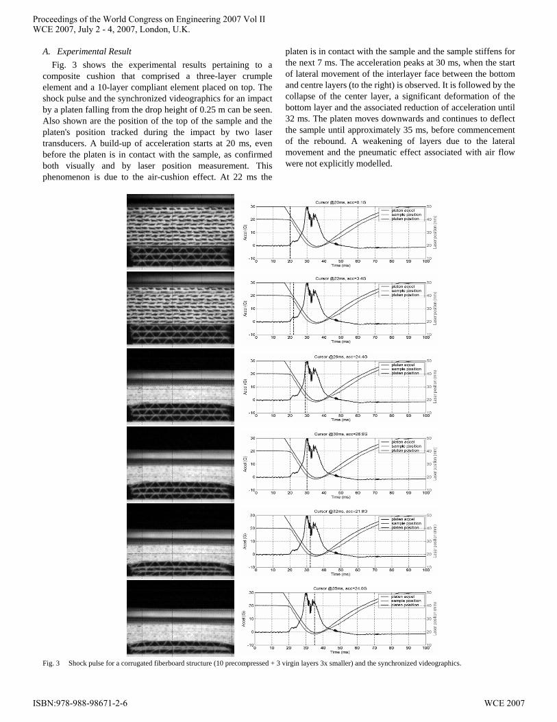
A. Experimental Result Fig. 3 shows the experimental results pertaining to a
composite cushion that comprised a three-layer crumple element and a 10-layer compliant element placed on top. The shock pulse and the synchronized videographics for an impact by a platen falling from the drop height of 0.25 m can be seen. Also shown are the position of the top of the sample and the platen's position tracked during the impact by two laser transducers. A build-up of acceleration starts at 20 ms, even before the platen is in contact with the sample, as confirmed both visually and by laser position measurement. This phenomenon is due to the air-cushion effect. At 22 ms the
platen is in contact with the sample and the sample stiffens for the next 7 ms. The acceleration peaks at 30 ms, when the start of lateral movement of the interlayer face between the bottom and centre layers (to the right) is observed. It is followed by the collapse of the center layer, a significant deformation of the bottom layer and the associated reduction of acceleration until 32 ms. The platen moves downwards and continues to deflect the sample until approximately 35 ms, before commencement of the rebound. A weakening of layers due to the lateral movement and the pneumatic effect associated with air flow were not explicitly modelled.
Fig. 3 Shock pulse for a corrugated fiberboard structure (10 precompressed + 3 virgin layers 3x smaller) and the synchronized videographics.
Proceedings of the World Congress on Engineering 2007 Vol IIWCE 2007, July 2 - 4, 2007, London, U.K.
ISBN:978-988-98671-2-6 WCE 2007

B. Results of Simulation and Discussion 1) Simulated Stress-Deflection Characteristics
In order to verify the model of stress-deflection characteristics of a single layer, a series of numerically simulated progressive compression tests at various strain rates were performed on the same model as for impacts of multilayer structures. It was achieved by switching gravitational field off, assigning infinitely large mass to the platen and using the ramping mode of the actuator in displacement control with suitably set low-pass filter. Fig. 4 compares two characteristics at the ramp speeds of 1 mm/s and 200 mm/s. Experimental investigations have shown that the effect of ramp speed due to increased damping becomes saturated at approximately 200 mm/s. The implemented nonlinear viscous damping model used an exponential decaying function to model this saturation. The model had an easy way of modifying the actual compression characteristics of a layer after it had been subjected to a precompression strain. A comparison of simulated stress-deflection characteristics at the ramp speed of 2 mm/s obtained for a virgin layer and its modified characteristics after a precompression to 60% strain are illustrated in Fig. 5. A buildup of hysteretic behavior starts to be more prominently visible, in comparison to the ramp speed of 1 mm/s.
Fig. 4 Simulated progressive stress-deflection characteristics.
Fig. 5 Simulated stress-deflection characteristics (at 2 mm/s) of a virgin layer and the modified characteristics after a precompression to 60% strain.
2) Simulated Impacts by a FreeFalling Mass
Fig. 6 presents simulation results of the situation similar to the experiment that is shown in Fig. 3, in which the center virgin layer collapsed first. The larger layers were subjected to 75% precompression. The characteristics of three virgin layers were numerically identical, yet the combination of energy flow through the structure led to the collapse of the center layer first. It was found that, when the layer that is in contact with the seismic base had been numerically weakened by only 0.0576% in comparison to the other two virgin layers, it collapsed first. It illustrates the chaotic nature of the process and the difficulties associated with experimental validation of numerical models, as the properties of most materials (and corrugated fiberboard in particular) cannot be controlled to that level of accuracy. The Shock Response Spectrum (SRS) in Fig. 7 depicts complex frequency content of the shock. In comparison to the simulation (Fig. 6), noticeably less prominent time separation in the shock pulse in Fig. 3 between the moments when the two layers experimentally collapsed, is caused by the lateral movement of interlayer face that initiated an almost simultaneous collapse of both layers.
Fig. 8 summarizes the effect of static stress (ratio of the mass weight to the contact area of larger precompressed layers) on cushioning performance. At lower static stress the shocks are shorter and with higher maximums. The collapsing of virgin layers is depicted by three lighter (in color) troughs, with the first one starting to appear at appr. 2.5 kPa when the first virgin layer collapses. Eventually, from appr. 3.6 kPa all three layers collapse, creating the safest cushioning range of static stress. It is maintained up to about 5 kPa when higher maximums are caused by the 'bottoming-in' and hardening of the whole structure. In reality, it is most likely that the mass subjected to shocks will have internal components with their own modes of vibrations. The SRS maps shown in Fig. 9 illustrate frequencies of these modes that should be avoided in order to reduce the shock amplification.
Table 1 shows parameters of virgin layers used in the simulations. Parameters of precompressed layers were scaled down proportionally to their size and the level of precompression.
Table 1 Parameters of virgin layer
Mass of a top layer 0.003 kg Mass of a bottom layer 0.003 kg Area 0.01 m2 Layer damping function (N)
))03.0/exp(1)(sgn(520 xx && −−
Contact spring damping function (N)
x&62.22
Contact spring restoring function (N)
)10*tan(82.84 3 x−π
.
Proceedings of the World Congress on Engineering 2007 Vol IIWCE 2007, July 2 - 4, 2007, London, U.K.
ISBN:978-988-98671-2-6 WCE 2007

Fig. 6 Results of a simulation: intralaminar forces at selected times during an impact and the corresponding shock pulse (drop height 0.25 m; static stress 3.5 kPa;
mass 3.5 kg).
Proceedings of the World Congress on Engineering 2007 Vol IIWCE 2007, July 2 - 4, 2007, London, U.K.
ISBN:978-988-98671-2-6 WCE 2007

Fig. 7 Shock Response Spectrum of the shock in Fig. 6.
Fig. 8 Time-static stress-shock acceleration maps of cushioning
performance.
Fig. 9 Shock Response Spectrum maps.
IV. CONCLUSION The model confirmed the chaotic dynamic compression a
multilayer structure with collapsible layers exhibits during the progression of impacts, detectable previously by high-speed videography.
REFERENCES [1] Sek M.A. and Rouillard V. "Behaviour of multi-layered corrugated
paperboard cushioning systems under impact loads", Applied Mechanics and Materials, 3-4, 2005, pp. 383-388.
[2] Sek M.A. and Rouillard V. "High-speed videographic study of engineered composite paperboard cushioning systems", Proc.15th IAPRI World Conference, Tokyo, Japan, 2006, pp. 258-262.
[3] Sek M.A., Rouillard V., Crawford S. and Tarash H. "Enhancement of cushioning performance with paperboard crumple inserts", Packaging Technology and Science, 18, 2005, pp. 273-278.
[4] Sek M.A., Minett M., Rouillard V. and Bruscella B. "A new method for the determination of cushion curves", Packaging Technology and Science, 13, 2000, pp. 249-255.
[5] Matlab® Reference Manual, Mathworks.
Proceedings of the World Congress on Engineering 2007 Vol IIWCE 2007, July 2 - 4, 2007, London, U.K.
ISBN:978-988-98671-2-6 WCE 2007