
NUMERICAL SIMULATION OF HYDRODYNAMIC LUBRICATION …sergio1/laboratorio/cilamce.pdf · NUMERICAL...
20
NUMERICAL SIMULATION OF HYDRODYNAMIC LUBRICATION IN COLD EXTRUSION Sérgio Tonini Button Departamento de Engenharia de Materiais FEM/UNICAMP - Caixa Postal 6122 13083-970 - Campinas - SP e-mail: [email protected] Abstract. Lubrication plays an important role in cold extrusion since efficient lubricants prevent direct metallic contact, with the reduction of extrusion loads and wear, and the improvement of products quality and tools life. In industrial processes lubrication is a time consuming operation and presents significant environmental impacts related to the disposal and discard of the many materials used to prepare and to lubricate the billets surface. Mineral oils are a good alternative to substitute the lubricants commonly used in cold extrusion, if the appropriate conditions are chosen to the process parameters, like lubricant viscosity, area reduction, speed and tool geometry. This work presents the numerical modeling of hydrodynamic lubrication in cold extrusion of steel parts. The model is based on the finite difference method, and provides results of temperature, stress and strain distributions in the lubricant film, in the tools and in the workpiece. Simulation and experimental results are compared to define the best conditions that promote stable thick film lubrication, preventing defects in the products and reducing the extrusion pressure. Keywords: hydrodynamic lubrication, cold extrusion, numerical analysis 1. INTRODUCTION Lubrication plays an important role in cold extrusion since efficient lubricants prevent direct metallic contact, with the reduction of extrusion loads and wear, and the improvement of products quality and tools life. Low friction coatings and oils are used to prevent seizure, reduce friction stresses, limit the wear and cool the tools. For instance, phosphate stearate coatings are excellent means of preventing seizure. Nevertheless, they are not sufficient to ensure the lubrication of the whole parts of the forming billet (Lazzarotto et al ., 1998-a). In industrial processes lubrication is a time consuming operation and presents significant environmental impacts related to the disposal and discard of the many materials used to prepare and to lubricate the billets surface. The global drive towards the use of lubricants benign to health and environment demands substitutes for traditional lubricants, often flammable with active elements such as chlorine, sulfur, and phosphorous, which are potentially hazardous, and often require the use of volatile organic solvents for their removal. Post-cleaning and disposal of these lubricants and solvents are difficult and costly. Therefore, it is necessary that lubricants more suitable for metal forming process be developed (Rao & Wei, 2001).
Transcript of NUMERICAL SIMULATION OF HYDRODYNAMIC LUBRICATION …sergio1/laboratorio/cilamce.pdf · NUMERICAL...

NUMERICAL SIMULATION OF HYDRODYNAMIC LUBRICATION IN COLD EXTRUSION
Sérgio Tonini Button Departamento de Engenharia de Materiais FEM/UNICAMP - Caixa Postal 6122 13083-970 - Campinas - SP e-mail: [email protected] Abstract. Lubrication plays an important role in cold extrusion since efficient lubricants prevent direct metallic contact, with the reduction of extrusion loads and wear, and the improvement of products quality and tools life. In industrial processes lubrication is a time consuming operation and presents significant environmental impacts related to the disposal and discard of the many materials used to prepare and to lubricate the billets surface. Mineral oils are a good alternative to substitute the lubricants commonly used in cold extrusion, if the appropriate conditions are chosen to the process parameters, like lubricant viscosity, area reduction, speed and tool geometry. This work presents the numerical modeling of hydrodynamic lubrication in cold extrusion of steel parts. The model is based on the finite difference method, and provides results of temperature, stress and strain distributions in the lubricant film, in the tools and in the workpiece. Simulation and experimental results are compared to define the best conditions that promote stable thick film lubrication, preventing defects in the products and reducing the extrusion pressure. Keywords: hydrodynamic lubrication, cold extrusion, numerical analysis 1. INTRODUCTION
Lubrication plays an important role in cold extrusion since efficient lubricants prevent direct metallic contact, with the reduction of extrusion loads and wear, and the improvement of products quality and tools life. Low friction coatings and oils are used to prevent seizure, reduce friction stresses, limit the wear and cool the tools. For instance, phosphate stearate coatings are excellent means of preventing seizure. Nevertheless, they are not sufficient to ensure the lubrication of the whole parts of the forming billet (Lazzarotto et al., 1998-a).
In industrial processes lubrication is a time consuming operation and presents significant environmental impacts related to the disposal and discard of the many materials used to prepare and to lubricate the billets surface. The global drive towards the use of lubricants benign to health and environment demands substitutes for traditional lubricants, often flammable with active elements such as chlorine, sulfur, and phosphorous, which are potentially hazardous, and often require the use of volatile organic solvents for their removal. Post-cleaning and disposal of these lubricants and solvents are difficult and costly. Therefore, it is necessary that lubricants more suitable for metal forming process be developed (Rao & Wei, 2001).

2. LUBRICATION IN COLD EXTUSION
Cold extrusion of steel parts is becoming increasingly important to the manufacturing industries due to recent advances in tool and press design and in tool materials. The main advantages of this process are good dimensional accuracy, smooth surface finish, reduced stock material and post machining, and improvements in mechanical properties (Jang et al., 2001).
However, this process requires high amount of mechanical energy to deform the workpiece. It means that high temperatures occur in the forming zone where workpiece and tool come into strong contact, which may impair or even completely nullify the effect of normal lubricants.
The mixed friction prevails in the forming zone, i.e., in the range of roughness peaks there is an extensive lubricant coat with the thickness of several molecular layers that prevents galling and seizure when pressures are not too high (boundary lubrication). At higher interface pressures the breakdown of this film is avoided by the presence of sufficient lubricant in the depression between the roughness peaks. The pressure in these valleys is built up in the forming zone and the lubricant is dragged to the tool-workpiece interface.
The chemical and physical-chemical properties of the surfaces of the tool and workpiece strongly influence galling and seizing, which can be prevented with chemical surface treatments like zinc phosphate coatings (Donofrio, 1999).
The zinc crystalline phosphatization coupled with a soap or MoS2 lubricant significantly improves the friction conditions at the interface and severe sequences of cold extrusion are possible. However, its implementation remains complex and costly and its reproducibility is sometimes random, so that its replacement by simpler processing which, above all, pollute less is topical (Dubar et al., 1998).
The coatings are formed during a sequential chemical process. Workpieces are first cleaned and submitted to an acid pickling. Then a zinc phosphate layer is formed and finally a soap, or MoS2 in the case of large area reductions, is applied. The soap (e.g., sodium or calcium stearate) reacts with the zinc phosphate to form a zinc stearate layer. Consequently, the quality of zinc phosphate stearate coatings depends on the physical and chemical parameters of the processing baths, such as temperature, concentration, acidity and submersion time (Lazzaroto et al., 1999).
The disposal and environmental control of the zinc phosphate sludge generated during and after cold forming process are also complex and costly. Baldy (1996) shows some alternatives to recycle this sludge and contribute significantly to reduce the cost of product manufacturing. For many industrial processes, the sludge consists of iron, zinc, manganese, nickel, phosphate, and oil. The products, which result from the recycling process, are oil, which may be used as a heating fuel, a zinc phosphate concentrate, and a cake of iron phosphate that can be further processed to an iron phosphate and iron oxide, which may be used as a pigment for paint.
Mineral oils are a good alternative to substitute the lubricants commonly used in cold extrusion, if the appropriate conditions are chosen to the process parameters, like lubricant viscosity, area reduction, speed and tool geometry. Komatsuzaki et al. (1996) showed that in forward extrusions, the anti-seizure property could be improved fairly simply when condensed phosphoric acids were directly added to lubricating oils together with monoalkyl phosphates or dialkyl phosphites. Lazzaroto et al. (1998) show a methodology to the selection of lubricant oils in cold metal forming processes, from a wide range of products available on the market, because the lubricant has an economic importance and its proper selection can save production costs.
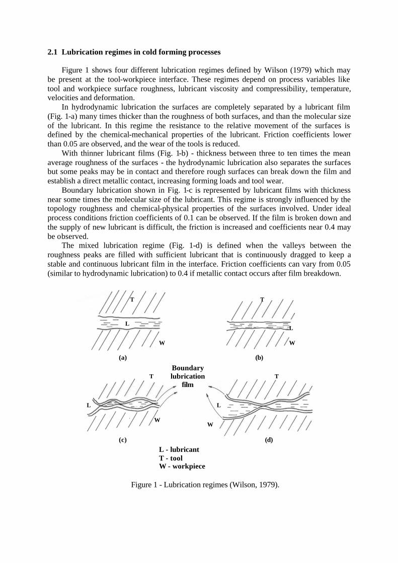
2.1 Lubrication regimes in cold forming processes Figure 1 shows four different lubrication regimes defined by Wilson (1979) which may
be present at the tool-workpiece interface. These regimes depend on process variables like tool and workpiece surface roughness, lubricant viscosity and compressibility, temperature, velocities and deformation.
In hydrodynamic lubrication the surfaces are completely separated by a lubricant film (Fig. 1-a) many times thicker than the roughness of both surfaces, and than the molecular size of the lubricant. In this regime the resistance to the relative movement of the surfaces is defined by the chemical-mechanical properties of the lubricant. Friction coefficients lower than 0.05 are observed, and the wear of the tools is reduced.
With thinner lubricant films (Fig. 1-b) - thickness between three to ten times the mean average roughness of the surfaces - the hydrodynamic lubrication also separates the surfaces but some peaks may be in contact and therefore rough surfaces can break down the film and establish a direct metallic contact, increasing forming loads and tool wear.
Boundary lubrication shown in Fig. 1-c is represented by lubricant films with thickness near some times the molecular size of the lubricant. This regime is strongly influenced by the topology roughness and chemical-physical properties of the surfaces involved. Under ideal process conditions friction coefficients of 0.1 can be observed. If the film is broken down and the supply of new lubricant is difficult, the friction is increased and coefficients near 0.4 may be observed.
The mixed lubrication regime (Fig. 1-d) is defined when the valleys between the roughness peaks are filled with sufficient lubricant that is continuously dragged to keep a stable and continuous lubricant film in the interface. Friction coefficients can vary from 0.05 (similar to hydrodynamic lubrication) to 0.4 if metallic contact occurs after film breakdown.
Figure 1 - Lubrication regimes (Wilson, 1979).
L
T
W
L
T
W
L
T
W
L
T
W
L - lubricant T - tool W - workpiece
Boundary lubrication
film
(b) (a)
(c) (d)

Stribeck's diagram (Fig. 2) shows the variation of the friction coefficient (µ) as a function of S (Stribeck's number) defined by the surfaces relative velocity (U), the lubricant viscosity (η) and by the interface load (F) for the three regimes: hydrodynamic (thick and thin film), mixed and boundary lubrication. With low velocities (region 1), few lubricant is carried to the interface and the boundary lubrication is established, direct metallic contact can occur and high friction coefficients are then observed.
Figure 2 - Stribeck's diagram (Cho et al., 2000).
With the increase of velocity, more lubricant is carried to the interface, filling the valleys, promoting a mixed lubrication regime (region 2), with an important reduction of friction. Above a critical value of S, defined as S*, the roughness peaks are flattened, more and more lubricant is carried to the interface and thus the hydrodynamic regime is established, the surfaces are separated and the friction coefficient reduced. In the region 3, the increase of friction coefficient with velocity is due to large amounts of lubricant which are carried to the interface that increases the pressure, the film thickness and the lubricant viscosity.
2.2 Analysis of the lubrication in cold extrusion
Figure 3-a shows the tooling set up commonly used in the cold extrusion of steel parts
(Lange, 1985), and Fig. 3-b shows four regions of the extrusion die: the inlet zone (region I), the work zone (region II), the cylindrical zone (region III), and the outlet zone (region IV).
In region I the workpiece is under elastic deformation and the lubricant film has a thickness equal to the workpiece-die clearance. Near to the entry of the work zone the pressure in the lubricant film is built up and the film thickness equals to h*.
The workpiece is plastically deformed in region II from the diameter D1 to D2, and the film thickness (h) is successively reduced in its convergent flow to the die apex O. The film thickness at the exit of region II will define the lubrication regime in the work zone according
Boundary lubrication
Mixed lubrication
Hydrodynamic lubrication
µ
FU
Sη.
=S*

to the relations defined by Wilson, 1979. Region III defines the final diameter of the product, the workpiece is again under elastic deformations and the film thickness has a constant thickness. Region IV is designed to relief the pressure on the workpiece and to keep the product without surface defects.
(a)
qD D D1 2
0
β
x
A
ZonesI II III IV
Ui
(b)
Figure 3 - Cold extrusion: (a) tooling set up (Lange, 1985)
and (b) regions of the extrusion die.
Baseplate
Pressure plate
Punch
Shrink ring
Extrusion die
Workpiece
Baseplate
Ejector
h*
h
Detail A

Reynolds equation. To calculate the pressure (p) and the thickness (h) of the lubricant film in the regions I and II the general Reynolds equation (Eq. (1)) (Cameron, 1966) can be used by assuming the follow considerations and the symbols shown in Fig. 4: § inertial forces are neglected , i.e., there are no external fields (gravity, magnetic or
electric) acting on the fluid. This assumption is valid when the fluid is nonconductor; § the pressure is constant along the film thickness, if considered that in this process this
thickness is very small (10-6 m); § the dimensions of the surfaces are very large when compared to the film thickness.
Therefore, it can be assumed that fluid flow in y direction is null; § there is no sliding between the tool and workpiece surfaces and the film, i.e., each
surface has the same velocity of the adjacent lubricant; § the lubricant is a "Newtonian" fluid. That can be assumed for mineral oils at pressures
near 1000 MPa (Cameron, 1966); § lubricant flow is laminar. It is valid if it is considered that extrusion speeds are high
and that the region of contact tool-workpiece (region II) is relatively small; § fluid inertia is neglected. Cameron, 1966 defines that even for fluid flow with
Reynolds number equal to 1000, film pressures are modified only 5% if the lubricant inertia is considered.
Figure 4 - Infinitesimal element of a pressurized fluid.
( ) ( ) ( )
−++∂∂
++∂∂
=
∂∂
∂∂
+
∂∂
∂∂
212121
33
ww2hVVy
hUUx
6yph
yxph
x ηη (1)
with U1 and U2 - velocities in the direction x V1 and V2 - velocities in the direction y w1 and w2 - velocities in the direction z
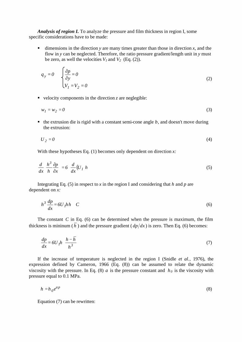
Analysis of region I. To analyze the pressure and film thickness in region I, some specific considerations have to be made: § dimensions in the direction y are many times greater than those in direction x, and the
flow in y can be neglected. Therefore, the ratio pressure gradient/length unit in y must be zero, as well the velocities V1 and V2 (Eq. (2)).
0VV
0yp
0q
21
y
==
=∂∂
= (2)
§ velocity components in the direction z are neglegible:
0ww 21 == (3) § the extrusion die is rigid with a constant semi-cone angle β, and doesn't move during
the extrusion:
0U 2 = (4)
With these hypotheses Eq. (1) becomes only dependent on direction x:
( )
=
∂∂
hUdxd
6xph
dxd
1
3
η (5)
Integrating Eq. (5) in respect to x in the region I and considering that h and p are dependent on x:
ChU6dxdp
h 13 += η (6)
The constant C in Eq. (6) can be determined when the pressure is maximum, the film thickness is mininum ( h ) and the pressure gradient ( dxdp ) is zero. Then Eq. (6) becomes:
−=
31h
hhU6
dxdp
η (7)
If the increase of temperature is neglected in the region I (Snidle et al., 1976), the expression defined by Cameron, 1966 (Eq. (8)) can be assumed to relate the dynamic viscosity with the pressure. In Eq. (8) α is the pressure constant and η0 is the viscosity with pressure equal to 0.1 MPa. p
0eαηη = (8) Equation (7) can be rewritten:

−=−
301p
h
hhU6
dxdp
e ηα (9)
The film thickness h can be related to x as βtanxh = (10) Then integrating the Eq. (9):
Ax1
tanx2
h
tan
U6e 22
01p +
−=−
ββ
αηα (11)
The constant A is defined by the boundary condition p = q when x = xi as shown in Fig. 3-b, with xi being a far point from region I, and q the pressure in the extrusion chamber. Then,
−+−=− −−
2i
2i
201qp
x
1
x
1tan2h
x1
x1
tan
U6ee
ββ
αηαα (12)
Assuming that plastic flow begins at x = x*, then qp 0 +=σ (13) where σ0 is the yield stress of the workpiece material. Then Eq. (12) becomes
( )
−+−=− −−
2i
2i
201q
x
1
x
1tan2h
x1
x1
tan
U6e1e 0
ββ
αηασα (14)
Substituting h* for x*tanβ,
( )( )
−
−−
+=
−−
2
20
*2i01
*i
q
*i
*i
hhU6
hhe1tane
hh
hh2h
αη
β ασα (15)
Assuming that in the passage from the region I to the region II we have the same lubricant flow, the same velocity and the same pressure gradient, it can be defined that
*hh = . Substituting in Eq. (15):
( )0e1tane
U3h
q01*
ασα β
αη−− −
= (16)
The initial value of the pressure q is determined with Eq. (17), considering only the work represented by the uniform deformation.

=
2
10 D
Dln2q σ (17)
As shown in Fig. 3-b, h* is the film thickness at the entry of region II. If h* is compared to the roughness of the surfaces in contact (die and workpiece), it can be defined the lubrication regime as discussed (Wilson, 1979). Analysis of region II. To calculate the pressure and the film thickness in the working zone (region II - Fig. 3-b), some considerations are assumed: § the workpiece material is isotropic, incompressible, continuous and uniform. Also it
is assumed that this material can be strain-hardened and follows the flow stress equation:
k
y Aεσ = (18) where A - mechanical strength coefficient k - strain hardening coefficient ε - true strain § the viscosity of the lubricant is dependent on the pressure and temperature:
( )θ∆αηη bp0 −= (19) where b - temperature constant ∆θ - increment of the lubricant temperature The average temperature of the film (θm) at any position x can be calculated considering the adiabatic heating of the workpiece and the heat transfer by conduction to the die and to the lubricant.
( )l
2
dbm k12U
5.0η
θθθ ++= (20)
where U - velocity kl - thermal conductivity of the lubricant θb - temperature of the workpiece θd - temperature of the die
( )
( ) 5.0bdl
2
5.0b
21y
ib T2k2U
h1
ck
1DD
lnc
−++
+= θθ
η
ρπρ
σθθ (21)
with θi - temperature of the workpiece at the entry of region II ρ - density of the workpiece material c - specific heat of the workpiece material kb - thermal conductivity of the workpiece material

T - extrusion time from D1 to D
( ) ( )
( )hZ
kk1
hZ
kkk2
Ukk
hZ
dl
dll
2
bdli
d+
++=
ηθθ
θ (22)
where Z - position in the die distant enough from the surface to reduce θd to θi. kd - thermal conductivity of the material of the die Since h depends on the pressure and also on the temperature of the lubricant (Eq. (19)), it is necessary to calculate p, θb, θd and θm at the same time. To determine the gradient of pressure in the region II, it has been used the slab method (von Karman, 1925), modified to consider the redundant work caused by the convergent flow present in the extrusion. In this model the redundant work was based in the works of Avitzur, 1965 and Pugh, 1964, from the upper bound theory. The slab method equation to determine the extrusion pressure is given:
( )βτσσ
cotD2
dD
d
dDdp
yy ++= (23)
where τ - shear stress in the lubricant film Assuming a Newtonian lubricant and a laminar flow:
hU
ητ = (24)
With Eq. (19) and assuming a constant plastic flow:
βcosDD
UU2
11
= (25)
( )
βθ∆αη
τ cosDD
Uh
bp 21
10
−
= (26)
Equation (18) is modified to consider the effect of redundant work on the flow stress:
k
11y D
Dln2A
+= εσ (27)
where ε1 - true strain in the entry of region II (Pugh, 1964)
−= β
β
βε cot
sin21
21 (28)

Therefore,
1k
11
y
DD
ln2DkA2
dD
d −
+−= ε
σ (29)
With Eq. (26) and Eq. (29), Eq. (23) can be rewritten:
+
+−=
−1k1
1 DD
ln2DkA2
dDdp
ε
( )
−
+
++
β
βθ∆αηε
sin
cosDD
Uh
bpDD
ln2AD2 22
11
0k
11 (30)
Equation (30) is a first-order ordinary differential equation that can be solved with the third order Runge-Kutta method (Carnahan et al., 1969).
)p,D(fdDdp
=
The initial boundary condition to iteration is defined by the pressure in the lubricant at the entry and at the exit of region II:
[ ] ∫−+=→= 1
1 0 yk1D1 dAqpDD
εεσε or
+−+=
+
1kA
Aqp1k
1k1
εε (31)
[ ] [ ] ∫+=→= 3
222dpDD yyD2
ε
εεεσσ or
[ ]( )
1kA
DD
ln2Ap1k
21k
3k
2
11D2 +
−+
+=
++ εεε (32)
3. NUMERICAL RESULTS AND DISCUSSION Table 1 shows the conditions used to simulate the cold extrusion of steel parts with the numerical method presented in this work. Four variables of influence were studied: three lubricant oils (LP - low pressure, MP - medium, and HP - high pressure), two workpiece materials (AISI 1020 and AISI 1035 steels), two semi-cone angles, and two area reductions. The initial velocity was kept constant and equal to U1 = 10 mm/s. The average surface roughness (Ra) were assumed to be equal to Ra = 1 µm to the die surface, and Ra = 6 µm to the workpiece surface. These simulation conditions were chosen to represent those conditions present in industrial extrusion processes. The constants are assumed to be typical for the workpiece material (steel) and the lubricants (oils).

Table 1
Workpiece material
AISI 1020 (as rolled)
σ0 = 330 (MPa) σy = 745.ε0.2 (MPa)
AISI 1035 (as rolled)
σ0 = 370 (MPa) σy = 902.ε0.17 (MPa)
Lubricants
Low pressure mineral oil
η0 = 0.1 (N.s/m2) α = 7,25.10-9 (Pa-1) b = 0.03 (ºC-1)
Medium pressure mineral oil
η0 = 0.6 (N.s/m2) α = 12.10-9 (Pa-1) b = 0.02 (ºC-1)
Extreme pressure mineral oil
η0 = 1.2 (N.s/m2) α = 18.10-9 (Pa-1) b = 0.015 (ºC-1)
Extrusion dies geometry
Die #1 D1 = 10 (mm) D2 = 9 (mm) β = 15º
Die #2 D1 = 10 (mm) D2 = 9 (mm) β = 20º
Die #3 D1 = 10 (mm) D2 = 8.3 (mm) β = 15º
Constants
ρ = 7800 kg/m3 c = 486 J/kg.ºC kl = 0.17 W/m.ºC Kb = 51.9 W/m.ºC
kd = 0.17 W/m.ºC Z = 5 mm
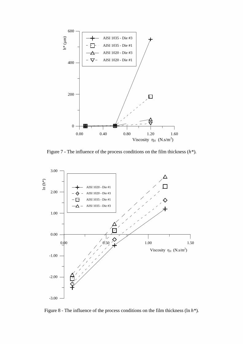
3.1 Analysis of the film thickness
Figures 5, 6, 7 and 8 show the influence of the process conditions on the film thickness at the entry of region II (h*). The ln(h*) is used in Fig. 6 and 8 to allow the analysis of very low film thickness.
The semi-cone angle of the die does not influence significantly the thickness, maybe because two angles typical in industry processes were chosen very close, and both showed the same effect on the drag of the lubricant to the work zone (region II).
The most significant influence to both workpiece materials is due to the lubricant viscosity. Considering the average surface roughness of the die and workpiece, it is observed that full hydrodynamic lubrication is achieved in the cold extrusion of AISI 1020 steel for viscosity η0 near 1.2 Ns/m2, typical of high pressure lubricants. In this case, film is greater than 10 mm and therefore die and workpiece surfaces are completely separated by a continuous and uniform film as stated by Wilson, 1979.

In the extrusion of AISI 1035 steel full hydrodynamic lubrication is established with medium pressure lubricants (η0 near 0.7 Ns/m2). As a high pressure is needed to the plastic yield of the workpiece material, more lubricant is dragged and entrapped in the work zone.
0.00 0.50 1.00 1.50
0.00
20.00
40.00
60.00
80.00
100.00
120.00
140.00
160.00
180.00
200.00
AISI 1020 - Die #1
AISI 1020 - Die #2
AISI 1035 - Die #1
AISI 1035 - Die #2
Figure 5 - The influence of the process conditions on the film thickness (h*).
Viscosity η0 (N.s/m2)
h* (µ
m)

0.00 0.50 1.00 1.50
-3.00
-2.00
-1.00
0.00
1.00
2.00
3.00
AISI 1020 - Die #1
AISI 1020 - Die #2
AISI 1035 - Die #1
AISI 1035 - Die #2
Figure 6 - The influence of the process conditions on the film thickness (ln h*).
Viscosity η0 (N.s/m2)
ln (h
*)
0.00 0.40 0.80 1.20 1.60
0
200
400
600
AISI 1035 - Die #3
AISI 1035 - Die #1
AISI 1020 - Die #3
AISI 1020 - Die #1
Figure 7 - The influence of the process conditions on the film thickness (h*).
0.00 0.50 1.00 1.50
-3.00
-2.00
-1.00
0.00
1.00
2.00
3.00
Legend Title
AISI 1020 - Die #1
AISI 1020 - Die #3
AISI 1035 - Die #1
AISI 1035 - Die #3
Figure 8 - The influence of the process conditions on the film thickness (ln h*).
Viscosity η0 (N.s/m2)
ln (h
*)
Viscosity η0 (N.s/m2)
h* (µ
m)
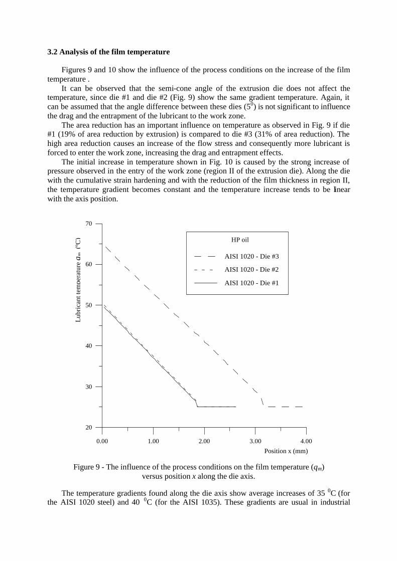
3.2 Analysis of the film temperature Figures 9 and 10 show the influence of the process conditions on the increase of the film temperature . It can be observed that the semi-cone angle of the extrusion die does not affect the temperature, since die #1 and die #2 (Fig. 9) show the same gradient temperature. Again, it can be assumed that the angle difference between these dies (50) is not significant to influence the drag and the entrapment of the lubricant to the work zone. The area reduction has an important influence on temperature as observed in Fig. 9 if die #1 (19% of area reduction by extrusion) is compared to die #3 (31% of area reduction). The high area reduction causes an increase of the flow stress and consequently more lubricant is forced to enter the work zone, increasing the drag and entrapment effects. The initial increase in temperature shown in Fig. 10 is caused by the strong increase of pressure observed in the entry of the work zone (region II of the extrusion die). Along the die with the cumulative strain hardening and with the reduction of the film thickness in region II, the temperature gradient becomes constant and the temperature increase tends to be linear with the axis position.
0.00 1.00 2.00 3.00 4.00
20
30
40
50
60
70
Legend Title
AISI 1020 - Die #3
AISI 1020 - Die #2
AISI 1020 - Die #1
Figure 9 - The influence of the process conditions on the film temperature (θm) versus position x along the die axis.
The temperature gradients found along the die axis show average increases of 35 0C (for the AISI 1020 steel) and 40 0C (for the AISI 1035). These gradients are usual in industrial
Position x (mm)
Lub
rica
nt te
mpe
ratu
re θ
m (
ºC) HP oil

processes and do not cause a significant variation on the lubricant viscosity η as defined in Eq. (19) with the parameter b shown in Table 1. As shown in figure 5 to 8 and already discussed, the film pressure has the main effect on the viscosity and consequently on the film thickness that defines the regime of lubrication. As shown in Fig. 10, the lubricant has a slight effect on the film temperature despite the different viscosities analyzed. This effect can be explained by the low viscous shear present in the film due to the small thickness observed in all tests simulated, as defined in Eq. (24) where the viscous shear stress (τ) is directly influenced by the ratio viscosity/film thickness.
8.8 9.2 9.6 10.0 10.4
20
30
40
50
60
AISI 1020 - Die #1 - MP oil
AISI 1020 - Die #1 - HP oil
AISI 1035 - Die #1 - MP oil
AISI 1035 - Die #1 - HP oil
Figure 10 - The influence of the process conditions on the film temperature (θm)
versus diameter D along the die axis.
3.2 Analysis of the film pressure Figures 11 and 12 show the influence of the process conditions on the pressure applied on the lubricant film along the position in the die axis. The pressure increases from the chamber pressure q to values typical of the workpiece flow stresss. This increase shows a high gradient representing a pressure build-up in the entry of region II (work zone), and is related to the increase of film thickness shown in Figs. 5 to 8. The pressure increase causes the establishment of a continuous and uniform film which thickness the lubrication regime present in the deformation process. Similar to the behavior of the increase in temperature, pressure gradients are not significantly affected by the semi-cone angle studied in this work.
Diameter D (mm)
Lub
rica
nt te
mpe
ratu
re θ
m (
ºC)

0 1 2 3 4
0
200
400
600
Figure 11 - The influence of the process conditions on the film pressure versus the position x along the die axis.
0 1 2 3 4
0
200
400
600
800
AISI 1035 - Die #3 - LP oil
AISI 1035- Die #3- MP oil
AISI 1035 - Die #3 - HP oil
Figure 12 - The influence of the process conditions on the film pressure versus the position x along the die axis
AISI 1020 - Die #1 - MP oil AISI 1020 - Die #2 - MP oil AISI 1020 - Die #3 - MP oil
Film
pre
ssur
e (M
Pa)
Position x (mm)
Film
pre
ssur
e (M
Pa)
Position x (mm)

The area reduction and the workpiece material show the most important effect on the build-up of the pressure. Again, the characteristics of the lubricant (Fig. 12) do not influence the pressure increase since the three lubricants studied in this work show the same pressure curves. As previously discussed, the increase in temperature and the small film thickness does not affect significantly the lubricant viscosity and therefore the pressure gradient. 3. CONCLUSIONS
The following conclusions can be drawn from the analysis of the numerical results: § the analytical/numerical model studied in this work showed to be appropriate to
simulate the lubrication in the cold extrusion. Some results related to film thickness, temperature and pressure are similar to the results obtained by other authors mentioned in the references.
§ the film thickness is strongly influenced by the workpiece material, area reduction and lubricant viscosity. If the material and the reduction are kept constant, the lubricant must be properly chosen to achieve hydrodynamic lubrication and to minimize friction.
§ the increase in the film temperature, as well as in the pressure, is only dependent on the area reduction. The lubricant properties do not affect significantly these gradients.
§ these numerical results must be compared to experimental results to verify how to change this analytical model to proper represent the real conditions present in the industrial process.
Acknowledgements The author wishes to thank FAPESP (Fundação de Amparo à Pesquisa do Estado de São Paulo) and CNPq (Conselho Nacional de Desenvolvimento Científico e Tecnológico) for their financial support to this work. REFERENCES Avitzur, 1965, Hydrostatic Extrusion, Trans. of ASME, J. of Eng. for Industry, vol. 87, n. 4,
pp. 487-488. Baldy, C.J., 1996, Recycling zinc phosphate sludge, Metal Finishing, vol. 94, n.11, pp. 23-30. Cameron, A., 1966, The principles of Lubrication, 1st ed., Longmans Green & Co., London. Carnaham, B., Luther, H.A. & Wilkes, J. O., 1969, Applied Numerical Methods, John Wiley
& Sons Inc., 1st ed., New York, pp. 430-433. Cho, S.W., Choi, S.M., Bae, C.S., 2000, Frictional modes of barrel shaped piston rings under
flooded lubrication, Tribology International, vol. 33, n. 8, pp. 545-551. Donofrio, J., 1999, Zinc phosphating, Metal Finishing, vol. 97, n. 5, Suppl. 1, pp. 71-86. Dubar, L., Bricout, J.P., Wierre, C. & Meignan, P., 1998, New surface processes for cold
forging of steels, Surface and Coatings Technology, vol. 102, n. 1-2, pp. 159-167. Jang, D.H, Ryou, T.K, Yoon, D.Y., 2001, Hwang, B.B., The process sequence design of a
power-assisted steering part, Journal of Materials Processing Technology, vol. 113, n. 1-3, pp. 87-92.
Von Karman, T.H., 1925, Beitrag zur Theorie des Walzvorganges, Ztschr. F. angew. Math. Un Mech., vol. 5, pp. 139-141.
Komatsuzaki S., Uematsu, T. & Narahara, T. 1996, Cold forming of steel with lubricating oils, Lubrication Engineering, vol. 52, n.3, pp. 259-266.
Lange, K. (ed.), 1985, Handbook of Metal Forming, 1st edition, McGraw-Hill. Lazzarotto, L., Dubar, L., Dubois, A., Ravassard, P. & Oudin, J., 1998-a, Three selection
criteria for the cold metal forming lubricating oils containing extreme pressure agents, Journal of Materials Processing Technology, vol. 80-81, pp. 245-250.
Lazzarotto, L., Dubar, L., Dubois, A., Bricout, J.P., Oudin, J.& Ravassard, P.A, 1998-b, Selection methodology for lubricating oils in cold metal forming processes, Wear vol. 215, n. 1-2, pp. 1-9 .
Lazzarotto, L., Maréchal, C., Dubar, L., Dubois, A. & Oudin, J., 1999, The effects of processing bath parameters on the quality and performance of zinc phosphate stearate coatings, Surface and Coatings Technology, vol. 122, n. 2-3, pp. 94-100.
Pugh, H.L.D., 1964, Redundant work and friction in the hydrostatic extrusion of pure aluminum and an aluminum alloy, J. of Mech. Eng. Science, vol. 6, n. 4, pp. 363-366.
Rao, K.P. & Wei, J.J., 2001, Performance of a new dry lubricant in the forming of aluminum alloy sheets ,Wear, vol. 249, n. 1-2, pp. 85-92.
Snidle, R.W., Parsons, B. & Dowson, 1.976, D., A thermal hydrodynamic theory for hydrostatic extrusion of low strength materials, Journal of Lubrication Technology, vol. 98, n. 2, pp. 335-343.
Wilson, W.R.D., 1979, Friction and lubrication in bulk metal forming processes, Journal of Applied Metalworking, vol. 1, n.1, pp. 7-9.