Numerical Simulation of Galvanic Corrosion Caused...
36
Defence R&D Canada – Atlantic DEFENCE DÉFENSE & Numerical Simulation of Galvanic Corrosion Caused by Shaft Grounding Systems in Steel Ship Hulls Y. Wang Technical Memorandum DRDC Atlantic TM 2004-284 January 2005 Copy No.________ Defence Research and Development Canada Recherche et développement pour la défense Canada
-
Upload
trinhquynh -
Category
Documents
-
view
217 -
download
0
Transcript of Numerical Simulation of Galvanic Corrosion Caused...

Defence R&D Canada – Atlantic
DEFENCE DÉFENSE&
Numerical Simulation of Galvanic
Corrosion Caused by Shaft Grounding
Systems in Steel Ship Hulls
Y. Wang
Technical Memorandum
DRDC Atlantic TM 2004-284
January 2005
Copy No.________
Defence Research andDevelopment Canada
Recherche et développementpour la défense Canada

This page intentionally left blank.
Numerical Simulation of Galvanic Corrosion Caused by Shaft Grounding Systems in Steel Ship Hulls
Y. Wang
Defence R&D Canada – Atlantic Technical Memorandum DRDC Atlantic TM 2004-284 January 2005

Abstract The shaft grounding systems used on board HMC ships have substantially reduced the shaft-to-hull resistance and, thus, improved the performance of the shipboard impressed current cathodic protection (ICCP) system. Under some circumstances, however, the shaft grounding systems have been left on while the ICCP system was turned off. This led to the accelerated corrosion of the exposed steel ship hull on paint holidays because of the substantial difference of the electric potentials between the steel ship hull and the nickel-aluminum bronze propellers. The extent of the increased corrosion rate of the steel ship hull depends on a variety of conditions including the locations and areas of the paint holidays on the ship hull, the overall paint degradation, and seawater domain where the ship is located. A boundary element code, named CPBEM, developed at Defence R&D Canada – Atlantic was used to numerically simulate the galvanic corrosion of the steel hull under the afore-mentioned various conditions. A box model was also used to demonstrate the effect of fluid domain on galvanic corrosion current and solution resistance. The modelling results have shown that the paint damage area significantly affects the galvanic corrosion rate, while the effect of the paint damage location on the galvanic corrosion rate is not significant when the ship is in an open sea. The little solution resistance encountered in the area away from the anodes and the cathode is attributed to the much larger cross sectional area for the galvanic current path in the large volume of seawater. The potential contours and galvanic corrosion current at various degrees of the paint degradation were also demonstrated.
Résumé L’utilisation des systèmes de mise à la terre de l’arbre d’hélice à bord des NCSM a permis de réduire considérablement la résistance entre l’arbre d’hélice et la coque, ce qui a entraîné une amélioration du rendement du système de protection cathodique par courant imposé (ICCP) des navires. Toutefois, dans certaines circonstances, le système ICCP est fermé alors que les systèmes de mise à la terre de l’arbre d’hélice fonctionnent toujours. Ces conditions provoquent une corrosion accélérée de la coque d’acier exposée du bâtiment, dans les zones non enduites de peinture (aussi appelées dimanches), car la différence de potentiel électrique entre la coque d’acier et les hélices en bronze de nickel-aluminium est très importante. L’importance des effets de l’augmentation de la vitesse de corrosion sur la coque d’acier dépend de diverses conditions, entre autres, l’emplacement des dimanches sur la coque et leur superficie, l’état de dégradation global de la couche de peinture, ainsi que la nature de l’eau de mer dans laquelle se trouve le navire.
DRDC Atlantic TM 2004-284 i

On a élaboré, à R & D pour la défense Canada – Atlantique, un code d’éléments limites, désigné par le sigle CPBEM, qui est utilisé pour réaliser la modélisation numérique de la corrosion galvanique de la coque d’acier, dans les diverses conditions susmentionnées. On a aussi employé un modèle boîte pour démontrer les effets du milieu liquide sur le courant de corrosion galvanique et la résistance de la solution. Les résultats de modélisation indiquent que la superficie de la zone de peinture altérée a des effets significatifs sur la vitesse de corrosion galvanique, alors que l’emplacement de ces zones n’en a pas, quand le navire est en haute mer. La faible résistance de la solution, dans la zone éloignée de l’anode et de la cathode, est attribuable à la section transversale beaucoup plus importante disponible pour la circulation du courant galvanique dans le grand volume d’eau de mer. La modélisation a aussi permis de bien établir les courbes de potentiel et le courant de corrosion galvanique, pour différents degrés de dégradation de la peinture.
ii DRDC Atlantic TM 2004-284
Executive Summary Introduction The shaft grounding systems used on board HMC ships have substantially reduced the shaft-to-hull resistance and, thus, improved the performance of the shipboard impressed current cathodic protection (ICCP) system. Under some circumstances, however, the shaft grounding systems have been left on while the ICCP system was turned off. This led to the accelerated corrosion of the exposed steel ship hull on paint holidays because of the substantial difference of the electric potentials between the steel ship hull and the nickel-aluminum bronze propellers. There are concerns on the distribution of the galvanic corrosion on the ship hull form. If the galvanic corrosion spreads evenly on the hull form, it would not cause significant damage. On the other hand, if the galvanic corrosion occurs only on the hull form in the vicinity of the propellers, severe damage to the ship hull would occur in a short period of time. The purpose of this paper is to numerically study the effect of the location and area of the paint damage in the steel hull on the galvanic corrosion of these holidays. Other factors that were also studied include the degree of overall paint degradation, and seawater domains where the ship is located. A box model was also used to demonstrate the effect of fluid domain on galvanic corrosion current and solution resistance. A boundary element code, named CPBEM, developed at Defence R&D Canada – Atlantic was used to numerically simulate the galvanic corrosion of the steel hull under the afore-mentioned various conditions. Results The modeling results showed insignificant effect of the location of paint damage on the galvanic corrosion in the steel hull for a ship in an open sea. Further analysis using a box model showed that in an open sea, most resistive drops were found to occur near the anode and the cathode. In other areas along the current path and far from the anode and the cathode, the solution resistance was very low because of the much larger cross sectional area provided by the large volume of electrolyte. The modelling results also showed that the paint damage area had by far the largest effect on the galvanic corrosion rate. The overall degraded paint coating could contribute a significant amount of the galvanic corrosion current, but still had very low galvanic corrosion rate because of the much larger surface area and equally distributed galvanic corrosion current around the hull surface. Significance The modeling results in this study have shown that severe galvanic corrosion could occur if the ICCP system was switched off and the shaft grounding system was left on for extended period of time, in particular, on newly painted steel hull that has fewer holidays no matter where these holidays are located on the ship hull. Therefore, to control the galvanic corrosion, the length of time that the shipboard ICCP system is turned off must be kept to a minimum.
DR
Wang, Y., 2004, Numerical Simulation of Galvanic Corrosion Caused by Shaft Grounding Systems in Steel Ship Hulls, DRDC Atlantic TM 2004-284, Defence R&D Canada – Atlantic.
DC Atlantic TM 2004-284 iii
Sommaire Introduction L’utilisation des systèmes de mise à la terre de l’arbre d’hélice à bord des NCSM a permis de réduire considérablement la résistance entre l’arbre d’hélice et la coque, ce qui a entraîné une amélioration du rendement du système de protection cathodique par courant imposé (ICCP) des navires. Toutefois, dans certaines circonstances, le système ICCP est fermé alors que les systèmes de mise à la terre de l’arbre d’hélice fonctionnent toujours. Ces conditions provoquent une corrosion accélérée de la coque d’acier exposée du bâtiment, dans les zones non enduites de peinture (aussi appelées dimanches), car la différence de potentiel électrique entre la coque d’acier et les hélices en bronze de nickel aluminium est très importante. La distribution de la corrosion galvanique sur la structure de la coque de navire est un sujet de préoccupation. Si la corrosion se forme uniformément sur l’ensemble de la coque, les dommages ne seront pas importants, mais par contre, si elle se limite à la zone de la coque à proximité des hélices, la coque pourrait être gravement endommagée à court terme. Le présent article porte sur des travaux de modélisation ayant pour but d’étudier les effets de l’emplacement et de la superficie de la zone de peinture altérée de la coque d’acier sur la corrosion galvanique des zones appelées dimanches. On a de plus étudié d’autres facteurs, notamment l’état de dégradation global de la peinture et la nature de l’eau de mer dans laquelle se trouve le navire. On a aussi employé un modèle boîte pour démontrer les effets du milieu liquide sur le courant de corrosion galvanique et la résistance de la solution. On a élaboré, à R & D pour la défense Canada – Atlantique, un code d’éléments limites, désigné par le sigle CPBEM, qui est utilisé pour réaliser la modélisation numérique de la corrosion galvanique de la coque d’acier, dans les diverses conditions susmentionnées. Résultats Les résultats de modélisation indiquent que l’emplacement de la zone de peinture altérée n’a pas d’effet significatif sur la corrosion galvanique de la coque d’acier d’un navire en haute mer. Une analyse plus poussée à l’aide d’un modèle boîte indique qu’en haute mer, la plupart des chutes de résistance se produisent à proximité de l’anode et de la cathode. Dans d’autres zones situées sur le parcours du courant et éloignées de l’anode et de la cathode, la résistance de la solution est très faible, ce qui est attribuable à la section transversale beaucoup plus importante offerte par le grand volume d’électrolyte. De plus, les résultats de modélisation indiquent que la superficie de la zone de peinture altérée est responsable des plus sérieux effets sur la vitesse de corrosion galvanique. Les zones de la couche de peinture où la dégradation est générale peuvent, en grande partie, faciliter la circulation du courant de corrosion galvanique, mais la superficie efficace beaucoup plus importante et la répartition égale du courant de corrosion galvanique à la surface de la coque se traduisent par une très faible vitesse de corrosion galvanique.
iv DRDC Atlantic TM 2004-284

Importance des résultats Les résultats de modélisation de la présente étude indiquent qu’une corrosion galvanique grave peut se produire si le système ICCP d’un navire est fermé alors que le système de mise à la terre de l’arbre d’hélice fonctionne pendant une période prolongée. C’est notamment le cas des coques d’acier fraîchement enduites de peinture ayant un nombre peu élevé de dimanches, et ce, peu importe l’emplacement de ces dimanches sur la coque du navire. Afin d’éliminer la corrosion galvanique, il faut donc réduire au minimum les périodes durant lesquelles le système ICCP du navire est fermé.
Wang, Y. 2004. Modélisation numérique de la corrosion galvanique des coques d’acier cT
DRD
ausée par les systèmes de mise à la terre de l’arbre d’hélice. RDDC Atlantique M 2004-284, R & D pour la défense Canada – Atlantique.
C Atlantic TM 2004-284 v
Table of Contents
Abstract ............................................................................................................................i
Executive Summary ...................................................................................................... iii
Sommaire .......................................................................................................................iv
Table of Contents...........................................................................................................vi
List of Figures .............................................................................................................. vii
Acknowledgements..................................................................................................... viii
1. Introduction.........................................................................................................1
2. Governing Equation and Boundary Conditions..................................................3
3. Boundary Element Code .....................................................................................4
4. Ship Model and Material Polarization Resistance Data .....................................5
5. Results and Discussions......................................................................................7
5.1 Polarization Curves.................................................................................7
5.2 Simulation Results ..................................................................................8
5.2.1 Effect of Distance .......................................................................8
5.2.2 Solution Resistance...................................................................10
5.2.3 Effect of Paint Damage Area ....................................................13
5.2.4 Effect of Paint Degradation ......................................................14
6. Summary and Conclusions ...............................................................................16
7. References.........................................................................................................18
Distribution list .............................................................................................................19
vi DRDC Atlantic TM 2004-284

List of Figures
Figure 1. Ship model for galvanic corrosion modelling................................................. 5
Figure 2. Polarization curve data for NAB, 350WT steel and degraded paint coating.. 7
Figure 3. Galvanic corrosion rates as a function of distance from the propeller ........... 9
Figure 4. Distribution of the galvanic corrosion current among the four paint damage sites (0.3 m2 paint damage at each site)......................................................................... 10
Figure 5. Potential contours on the box surface in both finite and infinite domains. .. 12
Figure 6. Effect of paint damage area on galvanic corrosion rate................................ 13
Figure 7. Potential contours on the ship hull computed at various stages of paint degradation. ........................................................................................................... 14
DRDC Atlantic TM 2004-284 vii

Acknowledgements The technical support of Mr. D. P. Brennan, Martec Limited, on the CPBEM code is gratefully acknowledged.
viii DRDC Atlantic TM 2004-284
1. Introduction Cathodic protection, both sacrificial anode and impressed current, is a widely used technique to supplement paint coating for corrosion protection of both military and commercial ocean-going fleets. The Canadian navy has historically adopted impressed current cathodic protection (ICCP) for preventing its steel-hulled vessels from corroding. Use of the shaft grounding systems extends the cathodic protection to the nickel-aluminum bronze propellers and steel shafts. There are two shaft-grounding systems that are currently used in the Canadian naval vessels. Following the early development work done by Carson and Buckett1, the brush/slip ring assembly of different material compositions was initially employed to ground the rotating shaft to the steel hull. The system, if properly installed and maintained, can reduce the electric contact resistance to a great extent. However, this passive electric bond system is subject to contamination of oil and grease and, thus, to increased electric contact resistance. To overcome this problem, Buckett and Evans2 developed an active shaft grounding system. This electronic feedback system removes the effect of the voltage drop in the brush contact and, therefore, maintains a very low electric bonding resistance. One disadvantage of an ICCP system is that it needs continuous DC power supply3. However, the shipboard ICCP system can break down and can be turned off for a variety of reasons. For example, the shipboard ICCP system needs to be turned off when divers work in the vicinity of the ship. When the ICCP system is off and the active shaft grounding system is left on, galvanic corrosion will occur on the paint damage areas, or holidays, as a result of substantial potential difference between the steel ship hull and the nickel-aluminum bronze propellers. Recent field measurements of the shaft current showed that as much as 73 kg/year hull metal was lost as a result of the galvanic corrosion4. There are concerns on the distribution of the galvanic corrosion on the ship hull form. If the galvanic corrosion spreads evenly on the hull form, it would not cause significant damage. On the other hand, if the galvanic corrosion occurs only on the hull form in the vicinity of the propellers, severe damage to the ship hull would occur in a short period of time. Computer-modelling techniques have become an acceptable practice in many corrosion-related studies in order to supplement experimental work. Munn5 summarized the early computer modelling development of galvanic corrosion and cathodic protection up to mid-1980. Zamani et al6 also surveyed different computational techniques used for modelling galvanic corrosion and cathodic protection. In the past 15 years, the use of the boundary element method (BEM) in both galvanic corrosion and cathodic protection studies has become commonplace7-10. The purpose of this paper is to numerically study the effect of the location and area of the paint damage in the steel hull on the galvanic corrosion of these holidays. Other
DRDC Atlantic ECR 2004-150 1

factors that were also studied include the degree of overall paint degradation, and seawater domains where the ship is located. A boundary element code, named CPBEM (Cathodic Protection Boundary Element Modelling), was used in the study.
2 DRDC Atlantic TM 2004-284
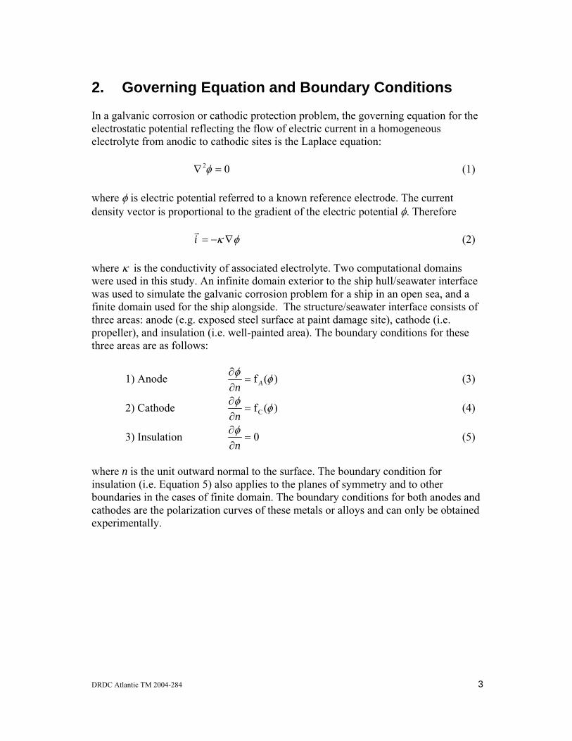
2. Governing Equation and Boundary Conditions In a galvanic corrosion or cathodic protection problem, the governing equation for the electrostatic potential reflecting the flow of electric current in a homogeneous electrolyte from anodic to cathodic sites is the Laplace equation: (1) 02 =∇ φ where φ is electric potential referred to a known reference electrode. The current density vector is proportional to the gradient of the electric potential φ. Therefore (2) φκ ∇−=i
r
where κ is the conductivity of associated electrolyte. Two computational domains were used in this study. An infinite domain exterior to the ship hull/seawater interface was used to simulate the galvanic corrosion problem for a ship in an open sea, and a finite domain used for the ship alongside. The structure/seawater interface consists of three areas: anode (e.g. exposed steel surface at paint damage site), cathode (i.e. propeller), and insulation (i.e. well-painted area). The boundary conditions for these three areas are as follows:
1) Anode )(f φφAn
=∂∂
(3)
2) Cathode )(fC φφ=
∂∂
n (4)
3) Insulation 0=∂∂
nφ
(5)
where n is the unit outward normal to the surface. The boundary condition for insulation (i.e. Equation 5) also applies to the planes of symmetry and to other boundaries in the cases of finite domain. The boundary conditions for both anodes and cathodes are the polarization curves of these metals or alloys and can only be obtained experimentally.
DRDC Atlantic TM 2004-284 3
3. Boundary Element Code The CPBEM code consists of a model generator, a solver, and a post-processor, which are integrated into a Windows interface. The code was developed for Defence R&D Canada – Atlantic under a series of research contracts11-13. The code is capable of modelling multiple cathodic and anodic areas with different polarization curves as boundary conditions. In addition, the solver is capable of computing the electric potentials and electrostatic fields at user-specified locations in the electrolyte. The constant element algorithm was implemented in the solver. The CPBEM model generator was specially designed to automatically generate and mesh a shipboard model. The user needs to describe only the boundaries of the region to be meshed. The model generator automatically creates an optimized mesh based on the user-defined element sizes. The anodic areas, cathodic areas, and insulation, as well as their corresponding properties (e.g. polarization curve data) can be defined interactively. In addition, the model generator can also automatically generate field points at user-defined locations in electrolyte where the electric field values are desired. The CPBEM post-processor displays both potential and current density profiles within its Windows interface. In addition, the post-processor also generates a Tecplot14 interface to allow users to review the modelling results using Tecplot’s advanced post-processing capabilities. The modelling results presented in this paper were plotted using Tecplot. The CPBEM code has been verified using various test cases15. The computer modelling results of electric potential profiles along a shipboard model using the CPBEM code were also compared to the physical scale modelling results and the modelling results obtained using commercial code BEASY16, and good agreement was obtained17,18.
4 DRDC Atlantic TM 2004-284
4. Ship Model and Material Polarization Resistance Data
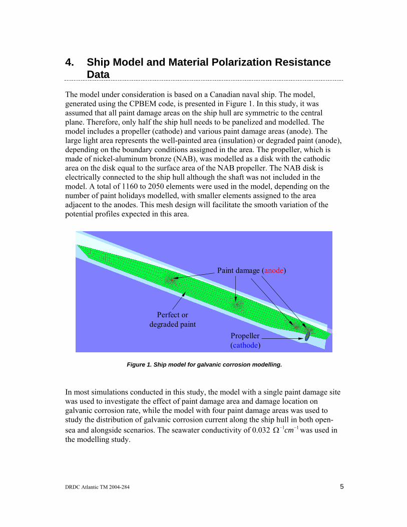
The model under consideration is based on a Canadian naval ship. The model, generated using the CPBEM code, is presented in Figure 1. In this study, it was assumed that all paint damage areas on the ship hull are symmetric to the central plane. Therefore, only half the ship hull needs to be panelized and modelled. The model includes a propeller (cathode) and various paint damage areas (anode). The large light area represents the well-painted area (insulation) or degraded paint (anode), depending on the boundary conditions assigned in the area. The propeller, which is made of nickel-aluminum bronze (NAB), was modelled as a disk with the cathodic area on the disk equal to the surface area of the NAB propeller. The NAB disk is electrically connected to the ship hull although the shaft was not included in the model. A total of 1160 to 2050 elements were used in the model, depending on the number of paint holidays modelled, with smaller elements assigned to the area adjacent to the anodes. This mesh design will facilitate the smooth variation of the potential profiles expected in this area.
Propeller(cathode)
Paint damage (anode)
Perfect or degraded paint
Propeller(cathode)
Paint damage (
Perfect or degraded paint
anode)
Figure 1. Ship model for galvanic corrosion modelling.
In most simulations conducted in this study, the model with a single paint damage site was used to investigate the effect of paint damage area and damage location on galvanic corrosion rate, while the model with four paint damage areas was used to study the distribution of galvanic corrosion current along the ship hull in both open-sea and alongside scenarios. The seawater conductivity of 0.032 was used in the modelling study.
11 −−Ω cm
DRDC Atlantic TM 2004-284 5

The polarization curve data needs to be provided for both cathodic area (i.e. NAB propeller) and anodic area (i.e. paint damage area and degraded paint). In this study, the potentiostatic technique was used to measure the polarization curves of NAB and 350WT steel specimens, while literature experimental data were used to calculate the polarization curves for degraded paint. The seawater used for the experiment was from the Halifax harbor. The air-purged seawater was circulated between a 400-liter tank and a 2-liter electrochemical test cell at about 0.2 liter/min in order to maintain a quiescent flow condition. The NAB specimen was from a used NAB propeller, while the steel specimen was from the steel hull material (i.e. 350WT). Prior to testing, the cylindrical specimen, with surface area of 5 cm2, was polished to 600-grit finish, rinsed, and then ultrasonically cleaned in an acetone solution for approximately 5 minutes. The specimen was then attached to an electrode holder and immersed in seawater for about 1 hour under open circuit condition. For the measurement of the anodic polarization curve, the steel specimen was then progressively polarized and maintained at each pre-selected anodic potential for 24 hours. For cathodic polarization curve measurement, each newly polished NAB specimen was used for each pre-selected cathodic polarization potential. The polarization current density was recorded at each pre-selected polarization potential, and the averaged current density at each pre-selected potential was used in the polarization curves. The seawater temperature was maintained at 14 to 16ºC during the experiment. The overall paint degradation is defined as the decrease in coating resistance as a result of the permeation of water, O2, and other ions into the paint coating. Since the coating resistance is significantly higher than the metal/electrolyte interface resistance, a linear polarization curve was assumed as the boundary condition for the degraded paint with the slope equal to the polarization resistance of the paint coating. As a result, the polarization curve can be expressed as (6) iREE pc =− where Ec is the corrosion potential of the steel. The literature data showed that for a 183 µm thick coating the coating resistance, Rp, varied from a value greater than 108 Ω⋅cm2 at start of exposure to a value close to 105 Ω⋅cm2 after 200-day exposure in artificial ocean water19. In the Canadian navy, 250 µm thick (dry film thickness) anti-corrosive coating was applied to the underwater hull of the naval vessels, and this was top coated with 125 µm anti-fouling coating. Three coating resistances, 107, 106, and 4 10 5 Ω⋅cm2 were used for modelling different stages of the paint degradation.
6 DRDC Atlantic TM 2004-284

5. Results and Discussions
5.1 Polarization Curves The polarization curve data for NAB, 350WT steel and degraded paints are presented in Figure 2. Those polarization curves were used as the boundary conditions for the galvanic corrosion modelling. The polarization curve for 350WT steel was used as boundary condition for the paint damage areas where bare steel was exposed. It should be noted that the polarization curves for both NAB and 350WT steel varied considerably with the surface conditions of the alloy or metal, seawater conditions (e.g. composition, O2 level, temperature), and ship operating conditions (e.g. alongside or at sea). One set of polarization curve data would not be able to predict galvanic corrosion rate for all conditions. The focus of this paper was to conduct parametric studies to investigate the effect of paint damage area and location, and paint degradation on the distribution of galvanic corrosion current, instead of predicting exact galvanic corrosion rate.
Current Density (mA/cm2)
Pot
entia
l(m
Vvs
Ag/
AgC
l)
10-5 10-4 10-3 10-2 10-1 100-700
-600
-500
-400
-300
-200
-100NABSteel (350WT)Degraded paint (Rp=107 Ω cm2)Degraded paint (Rp=106 Ω cm2)Degraded paint (Rp=4X10⁵ Ω cm2)
Figure 2. Polarization curve data for NAB, 350WT steel and degraded paint coating.
DRDC Atlantic TM 2004-284 7
5.2 Simulation Results
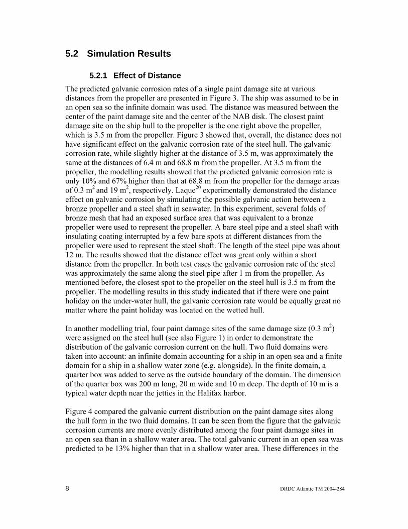
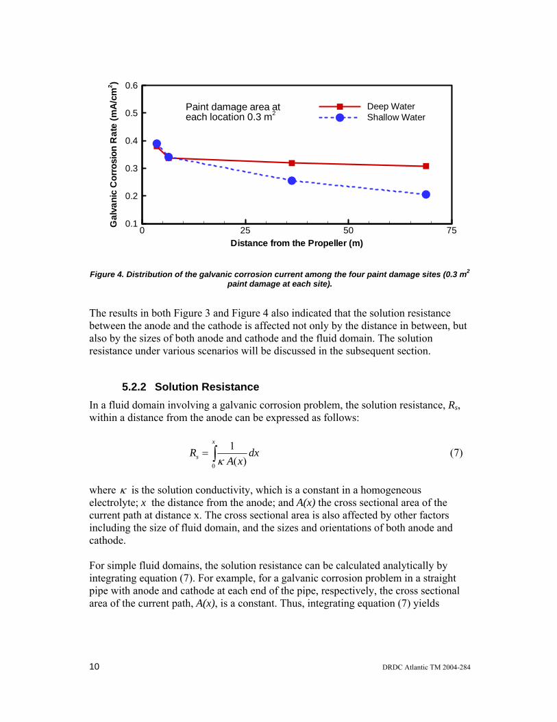
5.2.1 Effect of Distance The predicted galvanic corrosion rates of a single paint damage site at various distances from the propeller are presented in Figure 3. The ship was assumed to be in an open sea so the infinite domain was used. The distance was measured between the center of the paint damage site and the center of the NAB disk. The closest paint damage site on the ship hull to the propeller is the one right above the propeller, which is 3.5 m from the propeller. Figure 3 showed that, overall, the distance does not have significant effect on the galvanic corrosion rate of the steel hull. The galvanic corrosion rate, while slightly higher at the distance of 3.5 m, was approximately the same at the distances of 6.4 m and 68.8 m from the propeller. At 3.5 m from the propeller, the modelling results showed that the predicted galvanic corrosion rate is only 10% and 67% higher than that at 68.8 m from the propeller for the damage areas of 0.3 m2 and 19 m2, respectively. Laque20 experimentally demonstrated the distance effect on galvanic corrosion by simulating the possible galvanic action between a bronze propeller and a steel shaft in seawater. In this experiment, several folds of bronze mesh that had an exposed surface area that was equivalent to a bronze propeller were used to represent the propeller. A bare steel pipe and a steel shaft with insulating coating interrupted by a few bare spots at different distances from the propeller were used to represent the steel shaft. The length of the steel pipe was about 12 m. The results showed that the distance effect was great only within a short distance from the propeller. In both test cases the galvanic corrosion rate of the steel was approximately the same along the steel pipe after 1 m from the propeller. As mentioned before, the closest spot to the propeller on the steel hull is 3.5 m from the propeller. The modelling results in this study indicated that if there were one paint holiday on the under-water hull, the galvanic corrosion rate would be equally great no matter where the paint holiday was located on the wetted hull. In another modelling trial, four paint damage sites of the same damage size (0.3 m2) were assigned on the steel hull (see also Figure 1) in order to demonstrate the distribution of the galvanic corrosion current on the hull. Two fluid domains were taken into account: an infinite domain accounting for a ship in an open sea and a finite domain for a ship in a shallow water zone (e.g. alongside). In the finite domain, a quarter box was added to serve as the outside boundary of the domain. The dimension of the quarter box was 200 m long, 20 m wide and 10 m deep. The depth of 10 m is a typical water depth near the jetties in the Halifax harbor. Figure 4 compared the galvanic current distribution on the paint damage sites along the hull form in the two fluid domains. It can be seen from the figure that the galvanic corrosion currents are more evenly distributed among the four paint damage sites in an open sea than in a shallow water area. The total galvanic current in an open sea was predicted to be 13% higher than that in a shallow water area. These differences in the
8 DRDC Atlantic TM 2004-284
galvanic current and the galvanic current distribution are attributed to the change in solution resistance as a result of the change in the water domain where the ship was located (e.g. from an open sea to a shallow water zone).
Distance from the Propeller (m)
Gal
vani
cC
orro
sion
Rat
e(m
A/c
m2 )
0 25 50 750
0.1
0.2
0.3
0.4
0.5
0.60.3 m2
3 m2
10 m2
19 m2
Paint damage area
Figure 3. Galvanic corrosion rates as a function of distance from the propeller
DRDC Atlantic TM 2004-284 9
Distance from the Propeller (m)
Gal
vani
cC
orro
sion
Rat
e(m
A/c
m2 )
0 25 50 750.1
0.2
0.3
0.4
0.5
0.6
Deep WaterShallow Water
Paint damage area ateach location 0.3 m2
Figure 4. Distribution of the galvanic corrosion current among the four paint damage sites (0.3 m2 paint damage at each site).
The results in both Figure 3 and Figure 4 also indicated that the solution resistance between the anode and the cathode is affected not only by the distance in between, but also by the sizes of both anode and cathode and the fluid domain. The solution resistance under various scenarios will be discussed in the subsequent section.
5.2.2 Solution Resistance In a fluid domain involving a galvanic corrosion problem, the solution resistance, Rs, within a distance from the anode can be expressed as follows:
∫=x
s dxxA
R0 )(
1κ
(7)
where κ is the solution conductivity, which is a constant in a homogeneous electrolyte; x the distance from the anode; and A(x) the cross sectional area of the current path at distance x. The cross sectional area is also affected by other factors including the size of fluid domain, and the sizes and orientations of both anode and cathode. For simple fluid domains, the solution resistance can be calculated analytically by integrating equation (7). For example, for a galvanic corrosion problem in a straight pipe with anode and cathode at each end of the pipe, respectively, the cross sectional area of the current path, A(x), is a constant. Thus, integrating equation (7) yields
10 DRDC Atlantic TM 2004-284

A
lRs κ= , (8)
where l is the pipe length between the anode and the cathode. This equation shows a linear relationship between the pipe length and the solution resistance at a constant cross sectional area. For a spherical electrode of radius r0 in a spherical domain, the cross sectional area, A(x), at distance x from the spherical surface is expressed as . (9) ( 2
04 rxA += π ) Inserting Equation (9) into Equation (7), and then integrating Equation (7) yields
⎟⎟⎠
⎞⎜⎜⎝
⎛+
=004
1rx
xr
Rs κπ. (10)
This equation shows that most resistive drop occurs near the electrode surface. For example, the solution resistance at a distance from the surface equal to the radius of the electrode, i.e. x=r0, is already half of the value for an infinite distance. For more complicated electrode placement and water domains, numerical techniques need to be used to estimate the solution resistance. A box model was built to demonstrate the effect of fluid domain on solution resistance and galvanic corrosion current. The box was assumed to be 100 m long, 4 m wide and 4 m high. One end was assumed as anode and the other one as cathode. The remaining surfaces on the box were assumed as insulation. As the box was symmetric to the longitudinal centerline, the quarter box (i.e. 100 m long, 2 m wide, and 2 m high) was used in the computer modelling. The polarization curve data for the steel and NAB, which are presented in Figure 1, were used as boundary conditions for the anode and cathode, respectively. The same seawater conductivity data was also used for this modelling. Two fluid domains, finite domain and infinite domain, were used. In the finite domain, the box was filled with seawater and the box served as the outside boundary of the domain. In this case, all electrode surfaces faced inward. In the infinite domain, the box was assumed to be surrounded with large volume of seawater, and all electrode surfaces were assumed to face outward. The potential contours on the box surface in both finite and infinite domains are shown in Figure 5. This figure demonstrated that the two fluid domains produced significantly different potential distributions along the box surface. In the finite domain the potential contours were evenly distributed along the longitudinal direction. In other word, the potential profile along the box had a linear relationship with the distance from the anode. This linear relationship between the potential and the distance from the anode resulted from the constant cross sectional area through which
DRDC Atlantic TM 2004-284 11
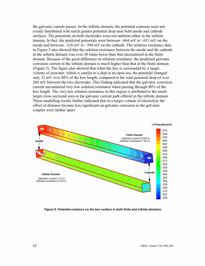
the galvanic current passes. In the infinite domain, the potential contours were not evenly distributed with much greater potential drop near both anode and cathode surfaces. The potentials on both electrodes were not uniform either in the infinite domain. In fact, the predicted potentials were between –664 mV to –651 mV on the anode and between –324 mV to –394 mV on the cathode. The solution resistance data in Figure 5 also showed that the solution resistance between the anode and the cathode in the infinite domain was over 30 times lower than that encountered in the finite domain. Because of the great difference in solution resistance, the predicted galvanic corrosion current in the infinite domain is much higher than that in the finite domain (Figure 5). The figure also showed that when the box is surrounded by a larger volume of seawater, which is similar to a ship in an open sea, the potential changed only 22 mV over 80% of the box length, compared to the total potential drop of over 260 mV between the two electrodes. This finding indicated that the galvanic corrosion current encountered very low solution resistance when passing through 80% of the box length. The very low solution resistance in this region is attributed to the much larger cross sectional area in the galvanic current path offered in the infinite domain. These modelling results further indicated that in a larger volume of electrolyte the effect of distance became less significant on galvanic corrosion as the galvanic couples were farther apart.
648 626 604 582 560 538
494 472 450 428
340 318 296
406 384
274
362
516
670648626604582560538516494472450428406384362340318296274252230
-1*Potential (mV)
236
670
560538
516
494 340
362
Galvanic current 1.41 ASolution resistance 0.23 Ω
Infinite Domain Cathode
Anode
664 ∼ 651
Finite DomainGalvanic current 0.056 A
Solution resistance 7.81 Ω
Figure 5. Potential contours on the box surface in both finite and infinite domains.
12 DRDC Atlantic TM 2004-284
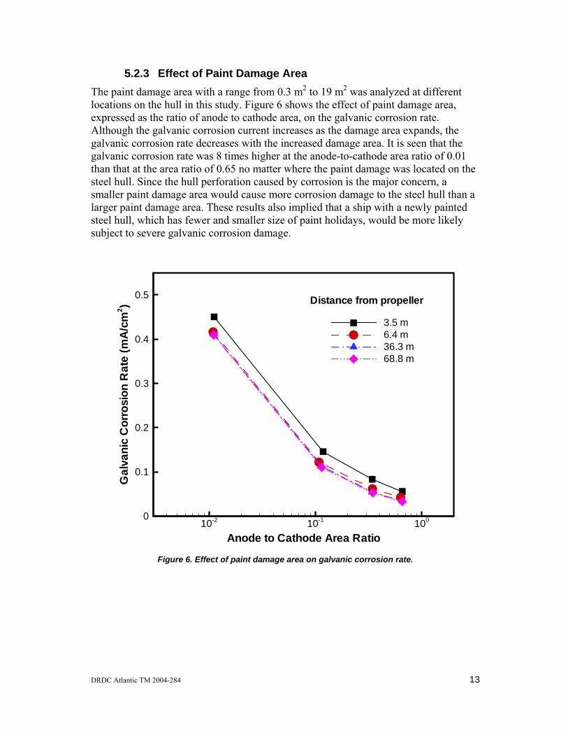
5.2.3 Effect of Paint Damage Area The paint damage area with a range from 0.3 m2 to 19 m2 was analyzed at different locations on the hull in this study. Figure 6 shows the effect of paint damage area, expressed as the ratio of anode to cathode area, on the galvanic corrosion rate. Although the galvanic corrosion current increases as the damage area expands, the galvanic corrosion rate decreases with the increased damage area. It is seen that the galvanic corrosion rate was 8 times higher at the anode-to-cathode area ratio of 0.01 than that at the area ratio of 0.65 no matter where the paint damage was located on the steel hull. Since the hull perforation caused by corrosion is the major concern, a smaller paint damage area would cause more corrosion damage to the steel hull than a larger paint damage area. These results also implied that a ship with a newly painted steel hull, which has fewer and smaller size of paint holidays, would be more likely subject to severe galvanic corrosion damage.
Anode to Cathode Area Ratio
Gal
vani
cC
orro
sion
Rat
e(m
A/c
m2 )
10-2 10-1 1000
0.1
0.2
0.3
0.4
0.5
3.5 m6.4 m36.3 m68.8 m
Distance from propeller
Figure 6. Effect of paint damage area on galvanic corrosion rate.
DRDC Atlantic TM 2004-284 13
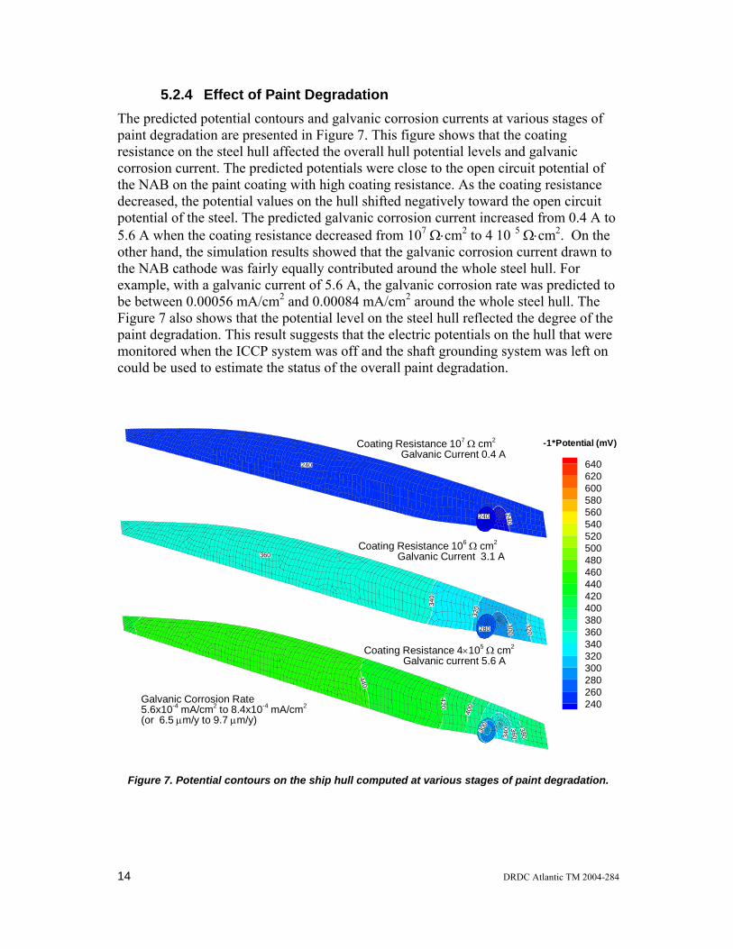
5.2.4 Effect of Paint Degradation The predicted potential contours and galvanic corrosion currents at various stages of paint degradation are presented in Figure 7. This figure shows that the coating resistance on the steel hull affected the overall hull potential levels and galvanic corrosion current. The predicted potentials were close to the open circuit potential of the NAB on the paint coating with high coating resistance. As the coating resistance decreased, the potential values on the hull shifted negatively toward the open circuit potential of the steel. The predicted galvanic corrosion current increased from 0.4 A to 5.6 A when the coating resistance decreased from 107 Ω⋅cm2 to 4 10 5 Ω⋅cm2. On the other hand, the simulation results showed that the galvanic corrosion current drawn to the NAB cathode was fairly equally contributed around the whole steel hull. For example, with a galvanic current of 5.6 A, the galvanic corrosion rate was predicted to be between 0.00056 mA/cm2 and 0.00084 mA/cm2 around the whole steel hull. The Figure 7 also shows that the potential level on the steel hull reflected the degree of the paint degradation. This result suggests that the electric potentials on the hull that were monitored when the ICCP system was off and the shaft grounding system was left on could be used to estimate the status of the overall paint degradation.
360
340
320
300
320280
Coating Resistance 106 Ω cm2
Galvanic Current 3.1 A
240
240
240
640620600580560540520500480460440420400380360340320300280260240
-1*Potential (mV)Coating Resistance 107 Ω cm2
Galvanic Current 0.4 A
380
36034030
0
400
420
440
Galvanic Corrosion Rate5.6x10-4 mA/cm2 to 8.4x10⁻⁴ mA/cm2
(or 6.5 µm/y to 9.7 µm/y)
Coating Resistance 4×10⁵ Ω cm2
Galvanic current 5.6 A
Figure 7. Potential contours on the ship hull computed at various stages of paint degradation.
14 DRDC Atlantic TM 2004-284
The above modelling results showed that both physical paint damage and the overall paint degradation on the steel hull contributed to galvanic corrosion current when the ICCP system was off and the active shaft grounding system was left on. The overall paint degradation could contribute substantial galvanic corrosion current as the paint coating aged because of very large paint coating area on the wetted hull. However, the sites with physical paint damage contributed much greater localized corrosion rate than that on degraded paint as a result of the smaller area and the much greater polarization current densities on the surface. These results imply that a high galvanic corrosion current does not always mean severe corrosion damage to the ship hull. This high galvanic current may be mainly contributed from the overall paint degradation around the ship hull. It is the total physical paint damage area that determines the extent of the localized corrosion damage to the steel hull.
DRDC Atlantic TM 2004-284 15
6. Summary and Conclusions Computer modelling for estimating the galvanic corrosion caused by the shaft grounding systems in the underwater steel hull has been demonstrated using the boundary element code CPBEM. The CPBEM code includes a model generator that is specially designed for generating models for a shipboard ICCP system or galvanic anode cathodic protection system. Factors affecting the galvanic corrosion that were considered in this study included location of the paint damage, size of the paint damage, and overall paint degradation. A box model was also used to demonstrate the effect of fluid domain on the galvanic corrosion current and solution resistance. The modelling results showed insignificant effect of the location of paint damage on the galvanic corrosion in the steel hull for a ship in an open sea. The results showed that for single paint damage, the galvanic corrosion rate was approximately the same no matter where the paint damage was located on the steel hull. In the case of more paint damage sites that had the same paint damage area and were located at different distances from the NAB disk, each paint damage site contributed approximately equally to the galvanic corrosion current. Further analysis using a box model showed that in an infinite domain, most resistive drops were found to occur near the anode and the cathode. In other areas along the current path and far from the anode and the cathode, the solution resistance was very low because of the much larger cross sectional area provided by the large volume of electrolyte. When the ship was in a shallow-water area (e.g. alongside), the paint damage site contributed less galvanic current as the site moved farther from the propeller. This increased distance effect was attributed to the increased solution resistance along the galvanic current path in the shallow-water zone. The overall paint degradation was shown to contribute to the total galvanic corrosion current in addition to the physical paint damage area. The results obtained showed that the degraded paint coating could contribute a significant amount of the galvanic corrosion current, but still had very low galvanic corrosion rate because of the much larger surface area and equally distributed galvanic corrosion current around the hull surface. The galvanic corrosion rate on the paint damage sites was much higher than that on the degraded paint coating. The paint damage area had by far the largest effect on the galvanic corrosion rate and determined the extent of localized corrosion damage to the steel hull. The results showed that as the paint damage area became smaller, the galvanic corrosion rate would become greater and, therefore, would take less time to perforate the steel hull. The modelling results in this study have shown that severe galvanic corrosion could occur if the ICCP system was switched off and the shaft grounding system was left on for extended period of time, in particular, on newly painted steel hull that has fewer holidays no matter where these holidays are located on the ship hull. Therefore, to
16 DRDC Atlantic TM 2004-284

control the galvanic corrosion, the length of time that the shipboard ICCP system is turned off must be kept to a minimum.
DRDC Atlantic TM 2004-284 17
7. References
1. R. Buckett and J.A.H. Carson, DRDC Report No. PNL-MAT-R-61-G, 1961. 2. R. Buckett and D.J. Evans, DRDC Report No. DREP-TM-71-3, 1972. 3. T.H. Rogers, “Marine Corrosion”, George Newnes Ltd. London, p. 195
(1968). 4. D.R. Lenard, CORROSION/2003, Paper No. 03231, NACE International,
Houston, TX (2003). 5. R.S. Munn, Computer Modelling in Corrosion, ASTM STP 1154, ed. R.S.
Munn, ASTM, pp. 215-228, 1992. 6. N.G. Zamani, J.F. Porter and A.A. Mufti. Int. J. Numer. Methods in Engng.,
23, pp. 1295-1311, 1986. 7. N.G. Zamani, Applied Mathematics and Computation, 26, pp. 119-134, 1988. 8. V.G. DeGiorgi, E.D. Thomas, A.I. Kaznoff, Computer Modelling in
Corrosion, ASTM STP 1154, ed. R.S. Munn. ASTM, pp. 265-276, 1992. 9. R.A. Adey and S.M. Niku, ASTM STP 1154, ed. R.S. Munn, ASTM, pp. 248-
263, 1992. 10. V.G. DeGiorgi, Boundary Elements XIX, Computational Mechanics
Publications: Southhampton, pp. 829-838, 1997. 11. Zamani, N.G., DRDC Atlantic contractor report, DREA CR/86/419, 1986. 12. Wallace, J.C., Brennan, D.P., Chernuka, M.W., DRDC Atlantic contractor
report, DREA CR 2002-039, 2003. 13. Brennan, D.P., MacKay. K.D., Wallace, J.C., Chernuka, M.W., DRDC
Atlantic contractor report, DRDC Atlantic CR 2002-221, 2003. 14. Tecplot 9.0 User’s Manual, Amtec Engineering Inc., Bellevue, Washington,
2001. 15. KarisAllen, K.J., Tawel, C.A., MacKay, K.D., and Brennan, D., DRDC
Atlantic contractor report, DREA CR/2001/014, 2001. 16. “BEASY Users Guide”, Computational Mechanics Inc, Billerica
Massachusetts, 2001. 17. Y. Wang, D.P. Brennan, J.F. Porter, and K.J. KarisAllen, “Evaluation of a
shipboard ICCP system using a boundary element code” Proceedings of the 2nd International Warship Cathodic Protection Symposium, Shrivenham, Swindon, UK, 2003.
18. K.D. MacKay, D.P. Brennan, Y. Wang and M.W. Chernuka, “Parametric studies of a shipboard impressed current cathodic protection system using boundary element codes” Proceedings of NACE Northern Area Eastern Conference 2003, Ottawa, 15-17 September 2003.
19. J. R. Scully, J. Electrochem. Soc, 136(4), pp. 979-990, (1989). 20. F.L. Laque, Marine Corrosion, John Wiley & Sons, New York, pp. 190-193
(1975).
18 DRDC Atlantic TM 2004-284
Distribution list
LIST PART 1: CONTROLLED BY DRDC ATLANTIC LIBRARY 2 DRDC ATLANTIC LIBRARY FILE COPIES 4 DRDC ATLANTIC (SPARES) 2 SCIENTIFIC AUTHORITY (One hard copy and one electronic copy) ________________ 8 TOTAL LIST PART 1 -------------------------------------------------------------------------------------------------------- LIST PART 2: DISTRIBUTED BY DRDKIM 3 1 NDHQ/DRDKIM 3 1 DMSS 3-5 (Hard copy)
NDHQ/Louis St-Laurent Building 555 Boul de la Carriere Hull, QC K1A 0K2
1 DMSS 2-4 (Hard copy) NDHQ/Louis St-Laurent Building 555 Boul de la Carriere Hull, QC K1A 0K2
________________ 3 TOTAL LIST PART 2 11 TOTAL COPIES REQUIRED -------------------------------------------------------------------------------------------------------- Original document held by DRDC Atlantic Drafting Office Any request by DRDC Atlantic staff for extra copies of this document should be directed to the DRDC ATLANTIC LIBRARY
DRDC Atlantic TM 2004-284 19

This page intentionally left blank.

DOCUMENT CONTROL DATA (Security classification of title, body of abstract and indexing annotation must be entered when the overall document is classified)
1. ORIGINATOR (the name and address of the organization preparing the document. Organizations for whom the document was prepared, e.g. Centre sponsoring a contractor's report, or tasking agency, are entered in section 8.) Defence R&D Canada – Atlantic Emerging Materials Section CFB Halifax, Bldg D-20 P.O. Box 99000 Stn Forces Halifax, Nova Scotia B3K 5X5
2. SECURITY CLASSIFICATION (overall security classification of the document
including special warning terms if applicable). UNCLASSIFIED
3. TITLE (the complete document title as indicated on the title page. Its classification should be indicated by the appropriate abbreviation (S,C,R or U) in parentheses after the title).
Numerical Simulation of Galvanic Corrosion Caused by Shaft Grounding Systems in Steel Ship Hulls
4. AUTHORS (Last name, first name, middle initial. If military, show rank, e.g. Doe, Maj. John E.)
Y. Wang
5. DATE OF PUBLICATION (month and year of publication of document)
January 2005
6a. NO. OF PAGES (total containing information Include Annexes, Appendices, etc).
20 (approx.)
6b. NO. OF REFS (total cited in document)
20
7. DESCRIPTIVE NOTES (the category of the document, e.g. technical report, technical note or memorandum. If appropriate, enter the type of
report, e.g. interim, progress, summary, annual or final. Give the inclusive dates when a specific reporting period is covered).
Technical Memorandum
8. SPONSORING ACTIVITY (the name of the department project office or laboratory sponsoring the research and development. Include address).
9a. PROJECT OR GRANT NO. (if appropriate, the applicable research
and development project or grant number under which the document was written. Please specify whether project or grant).
Na
9b. CONTRACT NO. (if appropriate, the applicable number under which the document was written).
Na
10a ORIGINATOR'S DOCUMENT NUMBER (the official document
number by which the document is identified by the originating activity. This number must be unique to this document.)
DRDC Atlantic TM 2004-284
10b OTHER DOCUMENT NOs. (Any other numbers which may be assigned this document either by the originator or by the sponsor.)
11. DOCUMENT AVAILABILITY (any limitations on further dissemination of the document, other than those imposed
by security classification) ( X ) Unlimited distribution ( ) Defence departments and defence contractors; further distribution only as approved ( ) Defence departments and Canadian defence contractors; further distribution only as approved ( ) Government departments and agencies; further distribution only as approved ( ) Defence departments; further distribution only as approved ( ) Other (please specify):
12. DOCUMENT ANNOUNCEMENT (any limitation to the bibliographic announcement of this document. This will normally correspond to the Document Availability (11). However, where further distribution (beyond the audience specified in (11) is possible, a wider announcement audience
may be selected).

13. ABSTRACT (a brief and factual summary of the document. It may also appear elsewhere in the body of the document itself. It is
highly desirable that the abstract of classified documents be unclassified. Each paragraph of the abstract shall begin with an indication of the security classification of the information in the paragraph (unless the document itself is unclassified) represented as (S), (C), (R), or (U). It is not necessary to include here abstracts in both official languages unless the text is bilingual). The shaft grounding systems used on board HMC ships have substantially reduced the shaft-to-hull resistance and, thus, improved the performance of the shipboard impressed current cathodic protection (ICCP) system. Under some circumstances, however, the shaft grounding systems have been left on while the ICCP system was turned off. This led to the accelerated corrosion of the exposed steel ship hull on paint holidays because of the substantial difference of the electric potentials between the steel ship hull and the nickel-aluminum bronze propellers. The extent of the increased corrosion rate of the steel ship hull depends on a variety of conditions including the locations and areas of the paint holidays on the ship hull, the overall paint degradation, and seawater domain where the ship is located. A boundary element code, named CPBEM, developed at Defence R&D Canada – Atlantic was used to numerically simulate the galvanic corrosion of the steel hull under the afore-mentioned various conditions. A box model was also used to demonstrate the effect of fluid domain on galvanic corrosion current and solution resistance. The modelling results have shown that the paint damage area significantly affects the galvanic corrosion rate, while the effect of the paint damage location on the galvanic corrosion rate is not significant when the ship is in an open sea. The little solution resistance encountered in the area away from the anodes and the cathode is attributed to the much larger cross sectional area for the galvanic current path in the large volume of seawater. The potential contours and galvanic corrosion current at various degrees of the paint degradation were also demonstrated.
14. KEYWORDS, DESCRIPTORS or IDENTIFIERS (technically meaningful terms or short phrases that characterize a
document and could be helpful in cataloguing the document. They should be selected so that no security classification is required. Identifiers, such as equipment model designation, trade name, military project code name, geographic location may also be included. If possible keywords should be selected from a published thesaurus. e.g. Thesaurus of Engineering and Scientific Terms (TEST) and that thesaurus-identified. If it not possible to select indexing terms which are Unclassified, the classification of each should be indicated as with the title). galvanic corrosion cathodic protection computer modeling boundary element code shaft grounding seawater ships

This page intentionally left blank.